EP4438838A1 - Door lock drive mechanism including a magnetic blocker, door and method for updating a door lock drive mechanism - Google Patents
Door lock drive mechanism including a magnetic blocker, door and method for updating a door lock drive mechanism Download PDFInfo
- Publication number
- EP4438838A1 EP4438838A1 EP23166246.1A EP23166246A EP4438838A1 EP 4438838 A1 EP4438838 A1 EP 4438838A1 EP 23166246 A EP23166246 A EP 23166246A EP 4438838 A1 EP4438838 A1 EP 4438838A1
- Authority
- EP
- European Patent Office
- Prior art keywords
- magnet
- shaft
- blocker
- door lock
- drive mechanism
- Prior art date
- Legal status (The legal status is an assumption and is not a legal conclusion. Google has not performed a legal analysis and makes no representation as to the accuracy of the status listed.)
- Granted
Links
Images


Classifications
-
- E—FIXED CONSTRUCTIONS
- E05—LOCKS; KEYS; WINDOW OR DOOR FITTINGS; SAFES
- E05B—LOCKS; ACCESSORIES THEREFOR; HANDCUFFS
- E05B47/00—Operating or controlling locks or other fastening devices by electric or magnetic means
- E05B47/06—Controlling mechanically-operated bolts by electro-magnetically-operated detents
- E05B47/0676—Controlling mechanically-operated bolts by electro-magnetically-operated detents by disconnecting the handle
-
- E—FIXED CONSTRUCTIONS
- E05—LOCKS; KEYS; WINDOW OR DOOR FITTINGS; SAFES
- E05B—LOCKS; ACCESSORIES THEREFOR; HANDCUFFS
- E05B47/00—Operating or controlling locks or other fastening devices by electric or magnetic means
- E05B47/0001—Operating or controlling locks or other fastening devices by electric or magnetic means with electric actuators; Constructional features thereof
- E05B47/0012—Operating or controlling locks or other fastening devices by electric or magnetic means with electric actuators; Constructional features thereof with rotary electromotors
-
- E—FIXED CONSTRUCTIONS
- E05—LOCKS; KEYS; WINDOW OR DOOR FITTINGS; SAFES
- E05B—LOCKS; ACCESSORIES THEREFOR; HANDCUFFS
- E05B47/00—Operating or controlling locks or other fastening devices by electric or magnetic means
- E05B47/06—Controlling mechanically-operated bolts by electro-magnetically-operated detents
- E05B47/0676—Controlling mechanically-operated bolts by electro-magnetically-operated detents by disconnecting the handle
- E05B47/0684—Controlling mechanically-operated bolts by electro-magnetically-operated detents by disconnecting the handle radially
- E05B47/0688—Controlling mechanically-operated bolts by electro-magnetically-operated detents by disconnecting the handle radially with a pivotally moveable coupling element
-
- E—FIXED CONSTRUCTIONS
- E05—LOCKS; KEYS; WINDOW OR DOOR FITTINGS; SAFES
- E05B—LOCKS; ACCESSORIES THEREFOR; HANDCUFFS
- E05B47/00—Operating or controlling locks or other fastening devices by electric or magnetic means
- E05B47/0001—Operating or controlling locks or other fastening devices by electric or magnetic means with electric actuators; Constructional features thereof
- E05B2047/0014—Constructional features of actuators or power transmissions therefor
- E05B2047/0018—Details of actuator transmissions
- E05B2047/0026—Clutches, couplings or braking arrangements
- E05B2047/0031—Clutches, couplings or braking arrangements of the elastic type
-
- E—FIXED CONSTRUCTIONS
- E05—LOCKS; KEYS; WINDOW OR DOOR FITTINGS; SAFES
- E05B—LOCKS; ACCESSORIES THEREFOR; HANDCUFFS
- E05B47/00—Operating or controlling locks or other fastening devices by electric or magnetic means
- E05B2047/0092—Operating or controlling locks or other fastening devices by electric or magnetic means including means for preventing manipulation by an external magnetic field, e.g. preventing opening by using a strong magnet
Definitions
- the present invention is related to a door lock drive mechanism, a door including said door lock drive mechanism and a method for updating a door lock drive mechanism.
- door locks may be electrically actuated and in this relation, it may be the case that the handle of a door may be coupled or decoupled from a locking means for locking the door.
- the handle when the handle is decoupled from the locking means, the handle can be freely moved and the door cannot be opened.
- the handle is connected to the door lock, e.g. when the handle is moved down, the door can be opened.
- FIG. 1 of said document corresponds to Figure 6 of the present application.
- the door lock drive mechanism has an electric motor 2 applying an electric current to a stator (the cross-section of the stator is shown on the left hand lower side of Figure 6 ), such that a shaft 4, which extends from the motor, is rotated. This rotation is transferred to actuate the door lock, which is shown on the left hand side of Figure 6 .
- a stator the cross-section of the stator is shown on the left hand lower side of Figure 6
- a shaft 4 which extends from the motor
- a C-shaped bracket (marked with A in Figure 6 ) mounted on an arm, which has on a rear side thereof permanent magnets (marked with PM in Figure 6 ).
- the arm When a permanent magnet is in the vicinity of the electric motor, the arm is rotated about an axis in the direction perpendicular to the rotation axis of the shaft and thereby, the C- shaped bracket engages the teeth provided on the outer circumferential surface of the rotor.
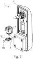
- a further system for preventing an unallowed opening of a door lock mechanism with an external magnet is disclosed in DE 10 2015 103 81 B4 . This system is shown in Figure 7 of the present application.
- the handle in a locked position is in a down position and fixed by the protruding element marked with P in said Figure, which is a shaft protruding from the electromotor 2.
- the electromotor is actuated to withdraw the shaft from the recess provided at the handle to disengage the handle from the locking position.
- a magnet blocker (see reference sign 16).
- This element is a plastic element, in which a permanent magnet PM is inserted.
- This element can be moved in the horizontal direction and is mounted in its neutral position with spring like extension elements.
- the present invention provides a further improvement of a system which counteracts the manipulation of a door lock drive mechanism with an external magnet.
- the magnet blocker has a specific configuration, such that the magnet blocker is moved from its neutral position into an engagement position with the shaft, such that the inner circumferential surface of the magnet blocker comes into contact with an outer circumferential surface of the shaft.
- a form- and/or a force-fit may be established, such that a rotation of the shaft due to induction of a magnetic force in the stator, when the external magnet is moved around the shaft in the circumferential direction, is prevented.
- the present magnet blocker is discriminated over DE 10 2015 100 381 B4 in that it prevents a rotation of the shaft when an external magnet is moved around the shaft in the circumferential direction.
- it is just prevented an extension or retraction of the shaft due to interaction of the inner circumferential surface of the through-hole of the magnet blocker with the groove of the shaft.
- the magnet blocker has a through-hole, which surrounds the shaft in its entire circumferential direction such that the through-hole in a neutral position is coaxial to the shaft and not in contact with an outer circumferential surface of the shaft.
- the through-hole of the magnet blocker defines an inner circumferential surface of the magnet blocker.
- the neutral position is a position in which no external magnet is provided in the vicinity of the system. In this neutral position, there are just forces acting on the magnet blocker which are due to the components of the door lock drive mechanism itself or the gravity.
- An engagement position is defined as a position in which the inner circumferential surface of the magnet blocker engages with the outer circumferential surface of the shaft, in particular that it is prevented a rotation of the shaft.
- a force-fit makes the prevention of rotation more efficient, such that there may be provided a form- and/or force-fit.
- a respective force-fit is then provided by correspondingly interacting surfaces at the inner circumferential surface of the magnet blocker with the outer circumferential surface of the shaft.
- the drive mechanism comprises a motor holder which holds the electromotor.
- the magnet blocker is in particular mounted to the motor holder.
- the motor holder may be a part of the housing, for example within a handle of the door, in which the motor is mounted, for example the motor may be mounted to the motor holder by force- and/or form-fit.
- the motor holder may have a protrusion or other fixing means for fixing a respective part of the magnet blocker.
- the magnet blocker should beneficially be fixed to the motor holder in such a way that the remaining part (base part of the motor blocker) is movable (in particular also partially rotatable) about the shaft.
- the magnet blocker may have the form of a disk, which may be made of a material which may be attracted by an external magnet. It is in particular beneficial that this material is a ferromagnetic material, such as iron, cobalt or nickel or respective alloys comprising such elements.
- the disk is adapted to be at least partially rotated about the central axis when the external magnet is moved around the shaft in the circumferential direction.
- the magnet blocker in particular has at least two arms which extend from an outer circumferential surface of the disk, in particular, there may be provided two arms which extend from the disk at two opposite directions in the radial direction of the disk.
- a different solution may be the provision of four arms.
- the four arms may extend for example in a cross-shape, wherein the four arms cross each other in the center of the through-hole.
- the arms may have a straight shape extending in the radial direction or may have a spiral configuration with respect to the center of the through-hole.
- These arms may spiral all in the same direction away from the disk. This configuration may be provided for two, three, or more arms, in particular this configuration is beneficial when two arms are provided.
- the spiral configuration of the arms allows a certain flexibility, thereby allowing the disk to rotate and move in its lateral direction and in this way, coming into contact with the shaft.
- the magnet blocker may have a centrosymmetric shape, centrosymmetric about an axis extending through the center of the through-hole.
- there may also be a mirror-symmetric configuration through a mirror plane extending perpendicularly to the disk surface and in which mirror plane the center of the through-hole extends. The aforementioned symmetry makes it easy to produce this magnet blocker and the magnet blocker can be easily integrated into the door lock drive mechanism.
- the arms of the magnet blocker may be integrally formed with the disk and thus provide the same material or may be provided as separate elements. If the arms are provided as separate elements, there are in particular mounting portions at the disk, at which proximal ends of the arms can be mounted. These arms may be mounted also by insert molding to the disk, also any other means in which a form- and/or force-fit for fixing the proximal ends of the arms to the disk can be provided. If the arms have a different material from the disk, it may be the case that the arms are made of a plastic material, wherein the disk is made a metal material, in particular formed as one unitary metal part. However, the magnet blocker is not delimited to a metal material. Also a magnetic material being of plastic, for example doped or mixed with magnetic elements in powder form can be used as material.
- the respective arms may have a distal end at which they are fixed to the motor holder. This may be done via a form- and/or force-fit.
- the respective distal ends may have an opening or through-hole which is mounted on a post extending from the motor holder.
- the posts at the motor holder may extend in the respective same direction as the shaft extends but offset from the shaft.
- the through-hole of the magnet blocker may have a circular cross-section and the surface of the shaft perpendicular in the region interacting with the through-hole may also have a circular cross-section.
- a circular cross-section may mean that there is a smooth cross-section without any teeth.
- the inner circumferential surface of the magnet blocker may be provided with teeth which protrude into an interior of the through-hole. These teeth in particular are distant in an equidistant manner from each other and provided along the entire inner circumferential surface of the through-hole.
- a certain inner gear teeth arrangement at the magnet blocker These teeth interact with corresponding teeth provided at the surface of the shaft at least in the portions at which the magnet blocker contacts the shaft when the external magnet comes close.
- the teeth may have a symmetric configuration and extend in radial direction of the through-hole or a radial direction of the respective shaft.
- the teeth may have an asymmetric configuration where protruding tips of the teeth all point into one specific direction, for example in counter clockwise or clockwise direction. For example, when the teeth at the inner circumferential surface of the through-hole are pointing counter clockwise, the teeth at the outer circumferential surface of the shaft point clockwise and vice versa.
- the teeth may have such an asymmetric configuration that, when interacting corresponding teeth on the outer circumferential surface of the shaft with teeth on the inner circumferential surface of the magnet blocker, the magnet blocker is blocked, at least in one direction.
- the shaft at its distal end is connected to an actuation mechanism, which, when the shaft is in an extended position, engages the handle of the door, such that it is unlocked and the door can be opened by actuating the handle.
- the aforementioned shaft may form a part of the electromotor and being the spindle of the electromotor interacting with the stator, however, it may be a separate element directly or indirectly attached or coupled to the spindle of the electromotor. However, the shaft rotates and simultaneously moves in a longitudinal direction upon receiving a respective force from the motor.
- the door lock drive mechanism may be adapted such that the rotation of the shaft is transformed to a translational movement of an element which may make a connection or disconnection between an handle of the door and the door lock depending on the translation direction of the element, wherein the element is in particular a link which is connected to the shaft via a spring which is engaged with a worm-like shaped element on the other circumferential surface of the shaft .
- the present invention provides also a door having the aforementioned door lock drive mechanism.
- the door has a handle.
- the complete door lock drive mechanism or at least the motor of the door lock drive mechanism is provided within the handle, such that the shaft extends at least substantially along the direction of the handle at which the user grips the handle.
- the present invention provides also a method for updating a door lock drive mechanism.
- the door lock drive mechanism may be any door lock mechanism in the prior art, wherein such a magnet blocker is not provided.
- This door lock drive mechanism needs to have an electric motor with a stator and a shaft.
- a magnet blocker is mounted around the shaft, such that the magnet blocker is adapted so that upon bringing the external magnet from a direction perpendicular to an extension direction of the shaft in a vicinity of the magnet blocker, the magnet blocker is moved from its neutral position into an engagement position with the shaft, such that the inner circumferential surface of the magnet blocker comes into contact with the outer circumferential surface of the shaft, such that a form- and/or force fit is provided therebetween, such that a rotation of the shaft due to induction of a magnetic force in the stator when the external magnet is moved around the shaft in the circumferential direction, is prevented.
- the door or the method there may also be provided the magnetic blocker as such.
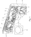
- Fig. 1 shows the conventional system from Assa Abloy which is on the market under the trademark H100.
- a handle 1 which may be mounted on a door.
- the user pushes the handle 1 down in the plane of the Figure. If the handle is engaged with the door lock, the handle allows unlocking and opening of the door. If the handle is disengaged from the door lock, via pushing the handle down, the door cannot be opened.
- Fig. 1 shown a status, in which the door can be opened by pushing down the handle.
- a motor 2 within the handle, there may be provided a motor 2.
- the motor 2 in the present case has a housing 3 from which at the front side thereof a shaft 4 extends.
- a stator is provided which interacts with a rotor.
- the rotor may be one piece with the electromotor spindle and usually only rotates. On this spindle there is in the present case force fitted the shaft 4.
- the presently described shaft may also be seen as part of the rotor and/or the spindle and thus generally the magnet blocker described in the following is at least adapted to prevent a rotation of the rotating part of the electromotor.
- the shaft 4 (which serves as rotor), such that the shaft upon electromagnetic actuation of the stator, rotates and thanks to the worm-like shape on the other circumferential surface of the shaft 4, it moves a spring 25, which is mounted about the shaft 4, which spring is connected to a link 6.
- the rotation of the shaft moves via the translational movement of the spring 25 the link 6 forward and backward in the direction B in Fig. 1 .
- the latches 7, 8, which interact with each other via their latch teeth 9, are pivoted about their pivot axis 10, 11, such as to bring the respective handle in engagement with the door lock or not.
- a small diameter section of the spring 25 which has a smaller diameter than a large diameter section at the distal side of the spring 25.
- the small diameter section allows a certain stability and facilitates the translational movement of the spring 25.
- the large diameter section provides a certain flexibility. It is not necessary to provide such a large diameter section as it is in the present example the case.
- the respective motor 2 including the housing 3 is held in a motor holder 12.
- the motor may be as in the present case snap-fitted in the motor holder 12 or it may be fixed by bolts or other fixing elements to the motor holder 12.
- This motor 2 is connected via connecting lines 13 to the circuit board 14 on which the electronic of the door lock drive mechanism is implemented and via which the motor 2 may be actuated.
- FIG. 1 there is schematically shown an external magnet with reference sign 15.
- this external magnet 15 When this external magnet 15 is moved around the shaft 4 and the handle 1 in a circumferential direction thereof, this may induce a magnetic force in the rotor, such that the shaft 4 rotates thereby, such that the door lock drive mechanism can be actuated via the external magnet in an unallowed manner as the spring is moved forward or backward.
- the actuation cinematic can be invers, such that the spring may move rearward in order to make it possible to open the door. Also any other mechanism can be provided.
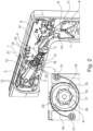
- Figs. 2a and 2b In order to prevent such an unallowed actuation via an external magnet, there is provided the inventive magnet blocker and an example thereof is shown in Figs. 2a and 2b.
- the basic configuration of the door lock drive is the same as in Fig. 1 , however, the only elements which are different, are encircled in the sketch on the right side of said Figure and they are shown in a magnified cross-section on the lower left side of said Figure.
- the magnet blocker has a through-hole 17 through which the shaft 4 extends.
- the through-hole 17 defines an inner circumferential surface of the magnet blocker 16 and the inner circumferential surface of the magnet blocker 16 entirely surrounds the shaft 4.
- the magnet blocker 16 in the present case is fixed to motor holder 12 via the arms 18.
- the arms 18 spiral away from the disk 19 and they spiral in the same direction.
- the distal end of the respective arm overlaps a portion of the respective other arm, such that at least, the proximal portion, at which the arms are fixed to the disk and the distal portion of the other arms, overlap each other.
- an O-formed attachment portion (having a though-hole) which may be mounted on a post 21 of the motor holder 12.
- a post 21 of the motor holder 12 there are provided two posts. These posts 21 extend in the same direction as the shaft 4 extends.
- An easy mounting of the magnet blocker is achieved by the fact that on top of the posts, there are rotatable latches 22 which allow to fix the end of the arms so that it does not come off of the motor holder 12.
- teeth 23 which are asymmetrical with respect to the radial direction of the through-hole, in particular, the teeth at the through-hole point all in the counter clockwise direction. These teeth 23 interact (upon engagement due to the force of the external magnet) with corresponding teeth 24 pointing in the clockwise direction provided at the outer circumferential surface of the shaft 4 .
- the external magnet in the sequence in Fig. 3 from the left top to the right bottom side moves in a clockwise direction circumferentially around the shaft 4/handle 1.
- the disk 19 of the magnet blocker (16) is attracted by the external magnet and thus moves in a direction within the plane of the disk and, thus, in the plane perpendicular to the shaft 4.
- the inner circumferential surface of this magnet blocker 16 interacts with the outer circumferential surface of the shaft 4.
- the corresponding teeth 23, 24 interact with each other.
- the teeth 23, 24, approximately in the 5 o'clock position interact with each other to implement the form-fit locking on one direction (clockwise direction).
- the respective disk 19 of the magnet blocker 16 itself may in a certain way rotate about its central axis against a retaining force of the portion where the arms are held by the post 21 at the motor holder 12.
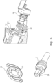
- Fig. 5 shows a different view of the embodiment described with reference to Figs. 2 and 3 .
- the magnet blocker 16 On the left upper side in Fig. 5 , there is shown the magnet blocker 16. On the left lower side in Fig. 5 , there is shown the shaft 4.
- the shaft 4 has at its proximal end, where it interacts with the spindle of the motor 2, the respective teeth 24 configuration, which interact with the teeth 23 provided at the inner circumferential side of the magnet blocker 16.
- the fixation of the magnet blocker 16 at the motor holder 12, via the post 21 can also be derived from Fig. 5 (right hand side).
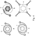
- Figs. 4a to e show different alternative configurations of the magnet blocker 16 and the outer circumferential surface of the shaft 4.
- the configuration shown in Fig. 4b is basically different from the configuration of the first embodiment, which was explained in the foregoing section in that the arms, with which the disk 19 of the magnet blocker 16 is mounted to the motor housing 3, are not integrally formed, but are formed as separate elements and made from a different material as the material of the disk.
- the disk may be made of a magnetic material which can be attracted by the magnet. It is in particular beneficial that this material is a ferromagnetic material, such as iron, cobalt or nickel or respective alloys comprising such elements.
- the arms may be made from a material, e.g. plastic, which cannot be attracted from the magnet.
- the arms are mounted on attachment portions provided at the outer circumferential surface of the disk 19.
- two arms are provided which spiral away, corresponding to the first embodiment.
- the embodiment shown in Fig. 4c is different from the configuration of the first embodiment in that the cross-section of the inner circumferential surface of the magnet blocker 16 and the outer circumferential surface of the shaft is circular. There are no teeth provided, thus, the respective interaction is simply done by a force-fit.
- the teeth are different from the configuration of the first embodiment, not asymmetric and point in one direction clockwise and counter clockwise, but are symmetrical with respect to the radial direction.
- the embodiment shown in Fig. 4d is different from the embodiment shown in Fig. 4b , such that instead of two arms, there are provided four arms which are not spiraling away but extend in radial direction away from the disk.
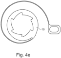
- Fig. 4e The embodiment shown in Fig. 4e is different from the fist embodiment, such that instead of two arms, there is provided only one single arm. This arm also spirals away from the body. Such one arm may also extend in the radial direction away from the disk instead of spiraling away. Although it is shown in said embodiment a situation, where the arms und the body form a unitary part (integrally formed), such one arm may also be provided as separate element as it is shown in the variants in Figures 4b and d.
- each embodiment there is preferably a form-fit between the arm and the motor holder 12 or another part of the housing.
- the distal portion there is pan O-formed attachment portion (having a though-hole) which may be mounted on a post 21 of the motor holder 12.
- the magnet blocker should beneficially be fixed to the motor holder in such a way that the remaining part (base part of the motor blocker) is movable (in particular also partially rotatable) about the shaft.
- the arms may be provided integrally with the disk 19 and/or made from the same material as the disk 19.
- Figs. 4a and c there may be provided four arms or more arms, which may be integrally and not integrally formed.
Landscapes
- Lock And Its Accessories (AREA)
Abstract
Description
- The present invention is related to a door lock drive mechanism, a door including said door lock drive mechanism and a method for updating a door lock drive mechanism.
- Generally, many types of door locks are known in the prior art. In particular, door locks may be electrically actuated and in this relation, it may be the case that the handle of a door may be coupled or decoupled from a locking means for locking the door. For example, when the handle is decoupled from the locking means, the handle can be freely moved and the door cannot be opened. When the handle is connected to the door lock, e.g. when the handle is moved down, the door can be opened.
- Generally, there are several mechanisms known in the prior art, which include an electric actuation of a door lock with the help of an electric motor. In this relation, it is also known that the door lock mechanisms can be manipulated by using a strong external magnet. With external magnets, the components of the door lock mechanism can be translated and moved in such a way that the handle allows to open the door. With such technique, securing features of a door lock system can be circumvented. There are also known several counter measurements in this relation.
- One counter measurement is disclosed in
DE 20 2014 101 158 U1 .Figure 1 of said document corresponds toFigure 6 of the present application. The door lock drive mechanism has anelectric motor 2 applying an electric current to a stator (the cross-section of the stator is shown on the left hand lower side ofFigure 6 ), such that ashaft 4, which extends from the motor, is rotated. This rotation is transferred to actuate the door lock, which is shown on the left hand side ofFigure 6 . However, when an external magnet is moved around the circumferential direction of the shaft, the shaft itself may be rotated and, thus, the door lock may be actuated with the external magnet. In order to prevent this, there is provided a C-shaped bracket (marked with A inFigure 6 ) mounted on an arm, which has on a rear side thereof permanent magnets (marked with PM inFigure 6 ). When a permanent magnet is in the vicinity of the electric motor, the arm is rotated about an axis in the direction perpendicular to the rotation axis of the shaft and thereby, the C- shaped bracket engages the teeth provided on the outer circumferential surface of the rotor. - A further system for preventing an unallowed opening of a door lock mechanism with an external magnet is disclosed in
DE 10 2015 103 81 B4Figure 7 of the present application. - Namely, the handle in a locked position is in a down position and fixed by the protruding element marked with P in said Figure, which is a shaft protruding from the
electromotor 2. Namely, the electromotor is actuated to withdraw the shaft from the recess provided at the handle to disengage the handle from the locking position. - In order to prevent a manipulation with an external magnet, there is provided a magnet blocker (see reference sign 16). This element is a plastic element, in which a permanent magnet PM is inserted.
- This element can be moved in the horizontal direction and is mounted in its neutral position with spring like extension elements. Thereby, when an external magnet is in the vicinity of the magnet blocker, the magnet blocker is moved from the coaxial position of the hole with respect to the shaft to a position, such that the inner circumferential surface of the magnet blocker interacts with a groove such that the shaft is prevented from moving forward or backward.
- However, the aforementioned explained methods and systems still have drawbacks and therefore, the present invention provides a further improvement of a system which counteracts the manipulation of a door lock drive mechanism with an external magnet.
- Therefore, it is provided a door lock drive mechanism having the features defined in claim 1.
- In particular, the magnet blocker has a specific configuration, such that the magnet blocker is moved from its neutral position into an engagement position with the shaft, such that the inner circumferential surface of the magnet blocker comes into contact with an outer circumferential surface of the shaft. Thereby, between these two surfaces, a form- and/or a force-fit may be established, such that a rotation of the shaft due to induction of a magnetic force in the stator, when the external magnet is moved around the shaft in the circumferential direction, is prevented.
- Namely, the present magnet blocker is discriminated over
DE 10 2015 100 381 B4 - As a difference to the aforementioned prior art
DE 20 2014 101 158 U1 , the magnet blocker has a through-hole, which surrounds the shaft in its entire circumferential direction such that the through-hole in a neutral position is coaxial to the shaft and not in contact with an outer circumferential surface of the shaft. The through-hole of the magnet blocker defines an inner circumferential surface of the magnet blocker. Thus, when the external magnet is moved around the shaft in a circumferential direction thereof, it is possible that in any position, there is an interaction between the inner circumferential surface of the through-hole and an outer circumferential surface of the shaft. - The neutral position is a position in which no external magnet is provided in the vicinity of the system. In this neutral position, there are just forces acting on the magnet blocker which are due to the components of the door lock drive mechanism itself or the gravity.
- An engagement position is defined as a position in which the inner circumferential surface of the magnet blocker engages with the outer circumferential surface of the shaft, in particular that it is prevented a rotation of the shaft.
- Generally, there may be an interaction just of a form-fit and no force-fit is necessary, however, a force-fit makes the prevention of rotation more efficient, such that there may be provided a form- and/or force-fit. A respective force-fit is then provided by correspondingly interacting surfaces at the inner circumferential surface of the magnet blocker with the outer circumferential surface of the shaft.
- According to a further development, the drive mechanism comprises a motor holder which holds the electromotor. The magnet blocker is in particular mounted to the motor holder.
- The motor holder may be a part of the housing, for example within a handle of the door, in which the motor is mounted, for example the motor may be mounted to the motor holder by force- and/or form-fit. The motor holder may have a protrusion or other fixing means for fixing a respective part of the magnet blocker. However, the magnet blocker should beneficially be fixed to the motor holder in such a way that the remaining part (base part of the motor blocker) is movable (in particular also partially rotatable) about the shaft.
- According to a further aspect, the magnet blocker may have the form of a disk, which may be made of a material which may be attracted by an external magnet. It is in particular beneficial that this material is a ferromagnetic material, such as iron, cobalt or nickel or respective alloys comprising such elements. The disk is adapted to be at least partially rotated about the central axis when the external magnet is moved around the shaft in the circumferential direction.
- The magnet blocker in particular has at least two arms which extend from an outer circumferential surface of the disk, in particular, there may be provided two arms which extend from the disk at two opposite directions in the radial direction of the disk. A different solution may be the provision of four arms. In this case, the four arms may extend for example in a cross-shape, wherein the four arms cross each other in the center of the through-hole.
- The arms may have a straight shape extending in the radial direction or may have a spiral configuration with respect to the center of the through-hole.
- These arms may spiral all in the same direction away from the disk. This configuration may be provided for two, three, or more arms, in particular this configuration is beneficial when two arms are provided. The spiral configuration of the arms allows a certain flexibility, thereby allowing the disk to rotate and move in its lateral direction and in this way, coming into contact with the shaft.
- In particular, the magnet blocker may have a centrosymmetric shape, centrosymmetric about an axis extending through the center of the through-hole. As an alternative or in addition, there may also be a mirror-symmetric configuration through a mirror plane extending perpendicularly to the disk surface and in which mirror plane the center of the through-hole extends. The aforementioned symmetry makes it easy to produce this magnet blocker and the magnet blocker can be easily integrated into the door lock drive mechanism.
- The arms of the magnet blocker may be integrally formed with the disk and thus provide the same material or may be provided as separate elements. If the arms are provided as separate elements, there are in particular mounting portions at the disk, at which proximal ends of the arms can be mounted. These arms may be mounted also by insert molding to the disk, also any other means in which a form- and/or force-fit for fixing the proximal ends of the arms to the disk can be provided. If the arms have a different material from the disk, it may be the case that the arms are made of a plastic material, wherein the disk is made a metal material, in particular formed as one unitary metal part. However, the magnet blocker is not delimited to a metal material. Also a magnetic material being of plastic, for example doped or mixed with magnetic elements in powder form can be used as material.
- The respective arms may have a distal end at which they are fixed to the motor holder. This may be done via a form- and/or force-fit. The respective distal ends may have an opening or through-hole which is mounted on a post extending from the motor holder. The posts at the motor holder may extend in the respective same direction as the shaft extends but offset from the shaft.
- The through-hole of the magnet blocker may have a circular cross-section and the surface of the shaft perpendicular in the region interacting with the through-hole may also have a circular cross-section. A circular cross-section may mean that there is a smooth cross-section without any teeth.
- Alternatively, the inner circumferential surface of the magnet blocker may be provided with teeth which protrude into an interior of the through-hole. These teeth in particular are distant in an equidistant manner from each other and provided along the entire inner circumferential surface of the through-hole. Thus, there is provided a certain inner gear teeth arrangement at the magnet blocker. These teeth interact with corresponding teeth provided at the surface of the shaft at least in the portions at which the magnet blocker contacts the shaft when the external magnet comes close.
- The teeth (of any of the magnet blocker and/or the shaft) may have a symmetric configuration and extend in radial direction of the through-hole or a radial direction of the respective shaft. Alternatively, the teeth may have an asymmetric configuration where protruding tips of the teeth all point into one specific direction, for example in counter clockwise or clockwise direction. For example, when the teeth at the inner circumferential surface of the through-hole are pointing counter clockwise, the teeth at the outer circumferential surface of the shaft point clockwise and vice versa.
- The teeth may have such an asymmetric configuration that, when interacting corresponding teeth on the outer circumferential surface of the shaft with teeth on the inner circumferential surface of the magnet blocker, the magnet blocker is blocked, at least in one direction.
- According to a further development, the shaft at its distal end is connected to an actuation mechanism, which, when the shaft is in an extended position, engages the handle of the door, such that it is unlocked and the door can be opened by actuating the handle.
- The aforementioned shaft may form a part of the electromotor and being the spindle of the electromotor interacting with the stator, however, it may be a separate element directly or indirectly attached or coupled to the spindle of the electromotor. However, the shaft rotates and simultaneously moves in a longitudinal direction upon receiving a respective force from the motor.
- According to a further development, the door lock drive mechanism may be adapted such that the rotation of the shaft is transformed to a translational movement of an element which may make a connection or disconnection between an handle of the door and the door lock depending on the translation direction of the element, wherein the element is in particular a link which is connected to the shaft via a spring which is engaged with a worm-like shaped element on the other circumferential surface of the shaft .
- According to a further aspect, the present invention provides also a door having the aforementioned door lock drive mechanism.
- The door has a handle. The complete door lock drive mechanism or at least the motor of the door lock drive mechanism is provided within the handle, such that the shaft extends at least substantially along the direction of the handle at which the user grips the handle.
- According to a further aspect, the present invention provides also a method for updating a door lock drive mechanism.
- The door lock drive mechanism may be any door lock mechanism in the prior art, wherein such a magnet blocker is not provided. This door lock drive mechanism needs to have an electric motor with a stator and a shaft.
- However, according to the present invention, a magnet blocker is mounted around the shaft, such that the magnet blocker is adapted so that upon bringing the external magnet from a direction perpendicular to an extension direction of the shaft in a vicinity of the magnet blocker, the magnet blocker is moved from its neutral position into an engagement position with the shaft, such that the inner circumferential surface of the magnet blocker comes into contact with the outer circumferential surface of the shaft, such that a form- and/or force fit is provided therebetween, such that a rotation of the shaft due to induction of a magnetic force in the stator when the external magnet is moved around the shaft in the circumferential direction, is prevented.
- Further, instead of providing the complete door lock drive mechanism, the door or the method, there may also be provided the magnetic blocker as such.
- Any of the aforementioned features as not mentioned explicitly are not inextricably linked to each other and any of the aforementioned features can be claimed separately.
- The present invention should be further explained with the help of the Figures and the further embodiments in which there is shown in
- Fig. 1
- a conventional door lock drive mechanism from the applicant called H 100,
- Figs. 2a and b
- the updated system according to the present invention, wherein the magnet blocker is used in the H100 system,
- Fig. 3
- the movement of the magnet blocker when an external magnet is moved around the shaft axis in circumferential direction,
- Figs. 4a to e
- different further embodiments of the magnet blocker interacting with the shaft,
- Fig. 5
- a mounted and demounted situation of the parts of the door lock drive mechanism,
- Fig. 6
-
Fig. 1 of the prior artDE 20 2014 101 158 U1 - Fig. 7
- is
Fig. 1 of theprior art DE 10 2015 100 381 B4 . -
Fig. 1 shows the conventional system from Assa Abloy which is on the market under the trademark H100. In this Figure, there is shown a partial cut of a view of a handle 1, which may be mounted on a door. The part of the handle 1, which extends in the Figure in the approximately horizontal direction, corresponds to the part which is gripped by the hand of the user. Usually, the user pushes the handle 1 down in the plane of the Figure. If the handle is engaged with the door lock, the handle allows unlocking and opening of the door. If the handle is disengaged from the door lock, via pushing the handle down, the door cannot be opened.Fig. 1 shown a status, in which the door can be opened by pushing down the handle. - Generally, within the handle, there may be provided a
motor 2. Themotor 2 in the present case has ahousing 3 from which at the front side thereof ashaft 4 extends. In the housing (not visible in the Figure), a stator is provided which interacts with a rotor. The rotor may be one piece with the electromotor spindle and usually only rotates. On this spindle there is in the present case force fitted theshaft 4. The presently described shaft may also be seen as part of the rotor and/or the spindle and thus generally the magnet blocker described in the following is at least adapted to prevent a rotation of the rotating part of the electromotor. - the shaft 4 (which serves as rotor), such that the shaft upon electromagnetic actuation of the stator, rotates and thanks to the worm-like shape on the other circumferential surface of the
shaft 4, it moves aspring 25, which is mounted about theshaft 4, which spring is connected to alink 6. Thus the rotation of the shaft moves via the translational movement of thespring 25 thelink 6 forward and backward in the direction B inFig. 1 . Due to this, thelatches latch teeth 9, are pivoted about theirpivot axis - As derivable from
Fig. 1 at the proximal side of thespring 25, where it is engaged with the worm-like shape on the other circumferential surface of theshaft 4 there is a small diameter section of thespring 25, which has a smaller diameter than a large diameter section at the distal side of thespring 25. The small diameter section allows a certain stability and facilitates the translational movement of thespring 25. The large diameter section provides a certain flexibility. It is not necessary to provide such a large diameter section as it is in the present example the case. - The
respective motor 2 including thehousing 3 is held in amotor holder 12. The motor may be as in the present case snap-fitted in themotor holder 12 or it may be fixed by bolts or other fixing elements to themotor holder 12. Thismotor 2 is connected via connectinglines 13 to thecircuit board 14 on which the electronic of the door lock drive mechanism is implemented and via which themotor 2 may be actuated. - In
Fig. 1 , there is schematically shown an external magnet withreference sign 15. When thisexternal magnet 15 is moved around theshaft 4 and the handle 1 in a circumferential direction thereof, this may induce a magnetic force in the rotor, such that theshaft 4 rotates thereby, such that the door lock drive mechanism can be actuated via the external magnet in an unallowed manner as the spring is moved forward or backward. - Although in the present case the spring moves forward to make the
latches - In order to prevent such an unallowed actuation via an external magnet, there is provided the inventive magnet blocker and an example thereof is shown in Figs. 2a and 2b. The basic configuration of the door lock drive is the same as in
Fig. 1 , however, the only elements which are different, are encircled in the sketch on the right side of said Figure and they are shown in a magnified cross-section on the lower left side of said Figure. - There is provided a
magnet blocker 16. The magnet blocker has a through-hole 17 through which theshaft 4 extends. The through-hole 17 defines an inner circumferential surface of themagnet blocker 16 and the inner circumferential surface of themagnet blocker 16 entirely surrounds theshaft 4. - The
magnet blocker 16 in the present case is fixed tomotor holder 12 via thearms 18. In this particular case, there are provided two arms. There may also be provided only one arm or more than two arms. These two arms extend from the outer circumferential surface of thedisk 19. Thearms 18 spiral away from thedisk 19 and they spiral in the same direction. In the present case, the distal end of the respective arm overlaps a portion of the respective other arm, such that at least, the proximal portion, at which the arms are fixed to the disk and the distal portion of the other arms, overlap each other. - At the distal portion, there is presently an O-formed attachment portion (having a though-hole) which may be mounted on a
post 21 of themotor holder 12. In the particular case, there are provided two posts. Theseposts 21 extend in the same direction as theshaft 4 extends. An easy mounting of the magnet blocker is achieved by the fact that on top of the posts, there are rotatable latches 22 which allow to fix the end of the arms so that it does not come off of themotor holder 12. - In the case in
Fig. 2 at the inner circumferential surface defined by the through-hole, there are providedteeth 23, which are asymmetrical with respect to the radial direction of the through-hole, in particular, the teeth at the through-hole point all in the counter clockwise direction. Theseteeth 23 interact (upon engagement due to the force of the external magnet) with correspondingteeth 24 pointing in the clockwise direction provided at the outer circumferential surface of theshaft 4 . - In a neutral position, which as shown in
Figs. 2 , the respective outer circumferential surface of theshaft 4 does not interact with the inner circumferential surface of themagnet blocker 16 and themagnet blocker 16 has no direct contact with an outer circumference of theshaft 4 and in this neutral position, the respectivemagnetic blocker 16 is coaxial with respect to theshaft 4. - Now, the magnet blocker function should be explained with reference to
Fig. 3 . - The external magnet in the sequence in
Fig. 3 from the left top to the right bottom side moves in a clockwise direction circumferentially around theshaft 4/handle 1. Thereby, thedisk 19 of the magnet blocker (16) is attracted by the external magnet and thus moves in a direction within the plane of the disk and, thus, in the plane perpendicular to theshaft 4. Thereby, the inner circumferential surface of thismagnet blocker 16 interacts with the outer circumferential surface of theshaft 4. - In this particular embodiment, the corresponding
teeth Fig. 3 , left top side, where the magnet is approximately in the 11 o'clock position, theteeth - When the
external magnet 15 is in the second step approximately in the 1 o'clock position, the correspondingteeth - Due to spiral extension configuration of the
arms 18, also therespective disk 19 of themagnet blocker 16 itself may in a certain way rotate about its central axis against a retaining force of the portion where the arms are held by thepost 21 at themotor holder 12. -
Fig. 5 shows a different view of the embodiment described with reference toFigs. 2 and3 . - On the left upper side in
Fig. 5 , there is shown themagnet blocker 16. On the left lower side inFig. 5 , there is shown theshaft 4. Theshaft 4 has at its proximal end, where it interacts with the spindle of themotor 2, therespective teeth 24 configuration, which interact with theteeth 23 provided at the inner circumferential side of themagnet blocker 16. The fixation of themagnet blocker 16 at themotor holder 12, via thepost 21 can also be derived fromFig. 5 (right hand side). -
Figs. 4a to e show different alternative configurations of themagnet blocker 16 and the outer circumferential surface of theshaft 4. - The configuration shown in
Fig. 4b is basically different from the configuration of the first embodiment, which was explained in the foregoing section in that the arms, with which thedisk 19 of themagnet blocker 16 is mounted to themotor housing 3, are not integrally formed, but are formed as separate elements and made from a different material as the material of the disk. - The disk may be made of a magnetic material which can be attracted by the magnet. It is in particular beneficial that this material is a ferromagnetic material, such as iron, cobalt or nickel or respective alloys comprising such elements.
- The arms may be made from a material, e.g. plastic, which cannot be attracted from the magnet. In the specific case, the arms are mounted on attachment portions provided at the outer circumferential surface of the
disk 19. In this particular embodiment, also two arms are provided which spiral away, corresponding to the first embodiment. - The embodiment shown in
Fig. 4c , is different from the configuration of the first embodiment in that the cross-section of the inner circumferential surface of themagnet blocker 16 and the outer circumferential surface of the shaft is circular. There are no teeth provided, thus, the respective interaction is simply done by a force-fit. - In the embodiment shown in
Fig. 4a , the teeth are different from the configuration of the first embodiment, not asymmetric and point in one direction clockwise and counter clockwise, but are symmetrical with respect to the radial direction. - The embodiment shown in
Fig. 4d is different from the embodiment shown inFig. 4b , such that instead of two arms, there are provided four arms which are not spiraling away but extend in radial direction away from the disk. - The embodiment shown in
Fig. 4e is different from the fist embodiment, such that instead of two arms, there is provided only one single arm. This arm also spirals away from the body. Such one arm may also extend in the radial direction away from the disk instead of spiraling away. Although it is shown in said embodiment a situation, where the arms und the body form a unitary part (integrally formed), such one arm may also be provided as separate element as it is shown in the variants inFigures 4b and d. - However in each embodiment there is preferably a form-fit between the arm and the
motor holder 12 or another part of the housing. Presently at the distal portion, there is pan O-formed attachment portion (having a though-hole) which may be mounted on apost 21 of themotor holder 12. There may be provided a protrusion or other fixing means for fixing a respective part of the magnet blocker. However, the magnet blocker should beneficially be fixed to the motor holder in such a way that the remaining part (base part of the motor blocker) is movable (in particular also partially rotatable) about the shaft. - The features of the aforementioned variants shown in the Figures may be combined with each other, which means, also in the embodiment in
Figs. 4b and d , the arms may be provided integrally with thedisk 19 and/or made from the same material as thedisk 19. - Also for the embodiment shown in
Figs. 4a and c , there may be provided four arms or more arms, which may be integrally and not integrally formed. - Also the configuration of the teeth or the non-provision of teeth may be exchanged for the different embodiments.
-
- 1
- handle
- 2
- motor
- 3
- housing
- 4
- shaft
- 5
- distal end of shaft
- 6
- link
- 7, 8
- latch
- 9
- latch theeth
- 10, 11
- pivot axis
- 12
- motor holder
- 13
- connecting lines
- 14
- circuit board
- 15
- external magnet
- 16
- magnet blocker
- 17
- though-hole
- 18
- arms
- 19
- disk
- 20
- attachment portion
- 21
- post
- 22
- rotatable latches
- 23
- theeth at the magnet blocker
- 24
- theeth at the shaft
- 25
- spring
Claims (15)
- Door lock drive mechanism comprisingan electromotor (2) having a stator,a shaft (4) which is adapted to be rotated by energization of the stator,and a magnet blocker (16) having a through-hole (17), through which the shaft (4) extends, such that the magnet blocker (16) surrounds the shaft (4) in its entire circumferential direction, such that the through-hole (17) in a neutral position, is coaxial to the shaft (4) and not in contact with an outer circumferential surface of the shaft (4),the through-hole (17) defines an inner circumferential surface of the magnet blocker (16),the magnet blocker (16) comprises a material which can be attracted by an external magnet (15), characterized in thatthe magnet blocker (16) is adapted in that upon bringing the external magnet (15) from a direction perpendicular to an extension direction of the shaft (4) in a vicinity of the magnet blocker (16), the magnet blocker is moved from its neutral position into an engagement position with the shaft (4) such that the inner circumferential surface of the magnet blocker (16) comes into contact with the outer circumferential surface of the shaft (4), such that a form- and/or force fit is provided therebetween, such that a rotation of the shaft (4) due to induction of a magnetic force in the stator, when the external magnet (15) is moved around the shaft (4) in the circumferential direction, is prevented.
- Door lock drive mechanism according to claim 1, characterized in that the door lock drive mechanism further comprises a motor holder (12), which holds the electromotor (2), wherein the magnet blocker (16) is mounted at the motor holder (12).
- Door lock drive mechanism according to claim 1 or 2, characterized in that the magnet blocker (16) has the form of a disk made from a material which can be attracted by the external magnet (15), wherein in particular the disk is adapted to be rotated about its central axis when the external magnet (15) is moved around the shaft (4) in the circumferential direction.
- Door lock drive mechanism according to claim 3, characterized in that the magnet blocker (16) has at least two arms (18) which extend form an outer circumferential surface of the disk, and in particular has two or three or four or more arms.
- Door lock drive mechanism according to claim 4, characterized in that the arms (18) have a spiral configuration and spiral all in the same direction away from the disk.
- Door lock drive mechanism according to any of claims 1 to 5, characterized in that the magnet blocker (16) is centrosymmetric about a central axis extending through the center of the trough-hole.
- Door lock drive mechanism according to any of claims 4 or 5 and 6 insofar as dependent on claim 4 or 5, characterized in that the arms (18) are integrally formed with the disk or provided as separate elements fixed to the disk.
- Door lock drive mechanism according to claim 7, characterized in that a respective distal end of the arms (18) is fixed to the motor holder (12) via a form-fit.
- Door lock drive mechanism according to any of claims 1 to 8, characterized in that the trough-hole has a circular cross-section and the corresponding outer circumferential surface of the shaft (4) has also a circular cross-section.
- Door lock drive mechanism according to any of claims 1 to 8, characterized in that the inner circumferential surface of the magnet blocker is provided with teeth (23) protruding therefrom in particular in an equidistant manner, and the corresponding outer circumferential surface of the shaft (4) has also teeth (24) protruding therefrom in particular in an equidistant manner and such that they, upon bringing the external magnet (15) from the direction perpendicular to the extension direction of the shaft (4), in a vicinity of the magnet blocker (16), are adapted to engage with the theeth (23) of the magnet blocker (16) in a form-fit.
- Door lock drive mechanism according to claim 10, characterized in that the teeth (23, 24) of the magnet blocker and/or of the shaft (4) are symmetric with respect to the radial direction of the through-hole.
- Door lock drive mechanism according to claim 10, characterized in that the teeth (23) of the magnet blocker are asymmetric with respect to the radial direction of the through-hole, such that when interacting with corresponding teeth (24) on the outer circumferential surface of the shaft (4), the rotation of the shaft (4) with respect to the magnet blocker (16) is blocked.
- Door lock drive mechanism according to any of claims 1 to 12, characterized in that the shaft (4) at its distal end is connected to an actuation mechanism, which, when the shaft (4) is located in its extended position, engages a handle (1) of a door such that it is unlocked and the door can be opened by actuating the handle (1).
- Door lock drive mechanism according to any of claims 1 to 13, characterized in that the door lock drive mechanism is adapted such that the rotation of the shaft is transformed to a translational movement of an element which may make a connection or disconnection between an handle of the door and the door lock depending on the translation direction of the element, wherein the element is in particular a link (6) which is connected to the shaft (4) via a spring (25) which is engaged with a worm-like shaped element on the other circumferential surface of the shaft (4).
- A method for updating a door lock drive mechanism, wherein the door lock drive mechanism comprises an electromotor (2) having a stator, a shaft (4) which is adapted to be rotated by energization of the stator, the method comprising:mounting a magnet blocker (16) in the door lock drive mechanism,wherein the magnet blocker (16) has a through-hole, through which the shaft (4) extends such that the magnet blocker (16) surrounds the shaft (4) in its entire circumferential direction, such that the through-hole in a neutral position, is coaxial to the shaft (4) and not in contact with an outer circumferential surface of the shaft (4),the through-hole defines an inner circumferential surface of the magnet blocker (16),the magnet blocker (16) comprises a material which can be attracted by an external magnet,the magnet blocker (16) is adapted in that upon bringing the external magnet (15) from a direction perpendicular to an extension direction of the shaft (4) in a vicinity of the magnet blocker (16), the magnet blocker is moved from its neutral position into an engagement position with the shaft (4), such that the inner circumferential surface of the magnet blocker (16) comes into contact with the outer circumferential surface of the shaft (4), such that a form- and/or force-fit is provided therebetween, such that a rotation of the shaft (4), due to induction of a magnetic force in the stator when the external magnet (15) is moved around the shaft (4) in the circumferential direction, is prevented.
Priority Applications (2)
| Application Number | Priority Date | Filing Date | Title |
|---|---|---|---|
| EP23166246.1A EP4438838B1 (en) | 2023-03-31 | 2023-03-31 | Door lock drive mechanism including a magnetic blocker and method for updating a door lock drive mechanism |
| ES23166246T ES3036803T3 (en) | 2023-03-31 | 2023-03-31 | Door lock drive mechanism including a magnetic blocker and method for updating a door lock drive mechanism |
Applications Claiming Priority (1)
| Application Number | Priority Date | Filing Date | Title |
|---|---|---|---|
| EP23166246.1A EP4438838B1 (en) | 2023-03-31 | 2023-03-31 | Door lock drive mechanism including a magnetic blocker and method for updating a door lock drive mechanism |
Publications (3)
| Publication Number | Publication Date |
|---|---|
| EP4438838A1 true EP4438838A1 (en) | 2024-10-02 |
| EP4438838C0 EP4438838C0 (en) | 2025-07-16 |
| EP4438838B1 EP4438838B1 (en) | 2025-07-16 |
Family
ID=85800520
Family Applications (1)
| Application Number | Title | Priority Date | Filing Date |
|---|---|---|---|
| EP23166246.1A Active EP4438838B1 (en) | 2023-03-31 | 2023-03-31 | Door lock drive mechanism including a magnetic blocker and method for updating a door lock drive mechanism |
Country Status (2)
| Country | Link |
|---|---|
| EP (1) | EP4438838B1 (en) |
| ES (1) | ES3036803T3 (en) |
Citations (5)
| Publication number | Priority date | Publication date | Assignee | Title |
|---|---|---|---|---|
| DE202007003197U1 (en) * | 2007-03-05 | 2007-05-31 | Sphinx Electronics Gmbh & Co. Kg | Electrical locking device for lock, has spring-impinged lifting magnet, consisting of cover and anchor, and locking washer is fastened at front anchor outside cover |
| DE202013103859U1 (en) * | 2013-08-27 | 2014-11-28 | BROSE SCHLIEßSYSTEME GMBH & CO. KG | Drive for adjusting an actuating element of a motor vehicle lock |
| DE202014101158U1 (en) | 2014-03-13 | 2015-06-16 | BROSE SCHLIEßSYSTEME GMBH & CO. KG | Drive component of a drive train of a motor vehicle lock |
| DE102015010381A1 (en) | 2015-08-07 | 2017-02-09 | Manssur Arbabian | Tuberosity implant |
| DE102015100381B4 (en) | 2014-06-27 | 2020-04-16 | Emka Beschlagteile Gmbh & Co. Kg | Swivel lever lock with a locking device for the locking part |
-
2023
- 2023-03-31 EP EP23166246.1A patent/EP4438838B1/en active Active
- 2023-03-31 ES ES23166246T patent/ES3036803T3/en active Active
Patent Citations (5)
| Publication number | Priority date | Publication date | Assignee | Title |
|---|---|---|---|---|
| DE202007003197U1 (en) * | 2007-03-05 | 2007-05-31 | Sphinx Electronics Gmbh & Co. Kg | Electrical locking device for lock, has spring-impinged lifting magnet, consisting of cover and anchor, and locking washer is fastened at front anchor outside cover |
| DE202013103859U1 (en) * | 2013-08-27 | 2014-11-28 | BROSE SCHLIEßSYSTEME GMBH & CO. KG | Drive for adjusting an actuating element of a motor vehicle lock |
| DE202014101158U1 (en) | 2014-03-13 | 2015-06-16 | BROSE SCHLIEßSYSTEME GMBH & CO. KG | Drive component of a drive train of a motor vehicle lock |
| DE102015100381B4 (en) | 2014-06-27 | 2020-04-16 | Emka Beschlagteile Gmbh & Co. Kg | Swivel lever lock with a locking device for the locking part |
| DE102015010381A1 (en) | 2015-08-07 | 2017-02-09 | Manssur Arbabian | Tuberosity implant |
Also Published As
| Publication number | Publication date |
|---|---|
| EP4438838C0 (en) | 2025-07-16 |
| EP4438838B1 (en) | 2025-07-16 |
| ES3036803T3 (en) | 2025-09-24 |
Similar Documents
| Publication | Publication Date | Title |
|---|---|---|
| EP1880073B1 (en) | Magnetic latch mechanism | |
| EP3635203B1 (en) | Lever return mechanism using magnets | |
| EP1846904B1 (en) | Magnetic latch mechanism | |
| CN109790730B (en) | motor vehicle lock | |
| CZ9803797A3 (en) | Connecting fitting | |
| EP4438838B1 (en) | Door lock drive mechanism including a magnetic blocker and method for updating a door lock drive mechanism | |
| JPH09502494A (en) | Device for electromagnetic locking of lock cylinder of lock | |
| CN101823470B (en) | Electric steering locking apparatus | |
| JP2023553240A (en) | locking device | |
| EP3060833B1 (en) | Magnet carrier assembly | |
| TW200938711A (en) | A modified driving mechanism to unlock and lock a lock latch | |
| EP3715999B1 (en) | Operating device | |
| JP2018161937A (en) | Lock structure of fuel lid | |
| WO2017109523A1 (en) | Bistable electromechanical actuator | |
| CN217631770U (en) | Back locking assembly adaptive to different door thicknesses and door lock | |
| JP2001295519A (en) | Locking set changing device | |
| EP4445815B1 (en) | Cooking pot locking mechanism and food processor comprising the cooking pot locking mechanism | |
| CN116847795A (en) | Surgical instrument locking device utilizing magnetic force | |
| CN217735156U (en) | Lockable small-angle compact magnetic suction lock body | |
| JP6099971B2 (en) | Door lock device | |
| JP3829901B2 (en) | Locking device | |
| CN111315950B (en) | Door locking device for a household appliance, in particular for a dishwasher | |
| JP2025520923A (en) | Magnetically Encoded Lock | |
| HU230885B1 (en) | Actuator with two fixed terminal | |
| EP4653651A1 (en) | Locking mechanism, door lock device and vehicle |
Legal Events
| Date | Code | Title | Description |
|---|---|---|---|
| PUAI | Public reference made under article 153(3) epc to a published international application that has entered the european phase |
Free format text: ORIGINAL CODE: 0009012 |
|
| STAA | Information on the status of an ep patent application or granted ep patent |
Free format text: STATUS: THE APPLICATION HAS BEEN PUBLISHED |
|
| AK | Designated contracting states |
Kind code of ref document: A1 Designated state(s): AL AT BE BG CH CY CZ DE DK EE ES FI FR GB GR HR HU IE IS IT LI LT LU LV MC ME MK MT NL NO PL PT RO RS SE SI SK SM TR |
|
| STAA | Information on the status of an ep patent application or granted ep patent |
Free format text: STATUS: REQUEST FOR EXAMINATION WAS MADE |
|
| 17P | Request for examination filed |
Effective date: 20241008 |
|
| RBV | Designated contracting states (corrected) |
Designated state(s): AL AT BE BG CH CY CZ DE DK EE ES FI FR GB GR HR HU IE IS IT LI LT LU LV MC ME MK MT NL NO PL PT RO RS SE SI SK SM TR |
|
| GRAP | Despatch of communication of intention to grant a patent |
Free format text: ORIGINAL CODE: EPIDOSNIGR1 |
|
| STAA | Information on the status of an ep patent application or granted ep patent |
Free format text: STATUS: GRANT OF PATENT IS INTENDED |
|
| GRAJ | Information related to disapproval of communication of intention to grant by the applicant or resumption of examination proceedings by the epo deleted |
Free format text: ORIGINAL CODE: EPIDOSDIGR1 |
|
| STAA | Information on the status of an ep patent application or granted ep patent |
Free format text: STATUS: REQUEST FOR EXAMINATION WAS MADE |
|
| INTG | Intention to grant announced |
Effective date: 20250228 |
|
| INTC | Intention to grant announced (deleted) | ||
| GRAP | Despatch of communication of intention to grant a patent |
Free format text: ORIGINAL CODE: EPIDOSNIGR1 |
|
| STAA | Information on the status of an ep patent application or granted ep patent |
Free format text: STATUS: GRANT OF PATENT IS INTENDED |
|
| GRAS | Grant fee paid |
Free format text: ORIGINAL CODE: EPIDOSNIGR3 |
|
| GRAA | (expected) grant |
Free format text: ORIGINAL CODE: 0009210 |
|
| STAA | Information on the status of an ep patent application or granted ep patent |
Free format text: STATUS: THE PATENT HAS BEEN GRANTED |
|
| INTG | Intention to grant announced |
Effective date: 20250515 |
|
| AK | Designated contracting states |
Kind code of ref document: B1 Designated state(s): AL AT BE BG CH CY CZ DE DK EE ES FI FR GB GR HR HU IE IS IT LI LT LU LV MC ME MK MT NL NO PL PT RO RS SE SI SK SM TR |
|
| REG | Reference to a national code |
Ref country code: GB Ref legal event code: FG4D |
|
| REG | Reference to a national code |
Ref country code: CH Ref legal event code: EP |
|
| REG | Reference to a national code |
Ref country code: IE Ref legal event code: FG4D |
|
| U01 | Request for unitary effect filed |
Effective date: 20250716 |
|
| U07 | Unitary effect registered |
Designated state(s): AT BE BG DE DK EE FI FR IT LT LU LV MT NL PT RO SE SI Effective date: 20250722 |
|
| REG | Reference to a national code |
Ref country code: ES Ref legal event code: FG2A Ref document number: 3036803 Country of ref document: ES Kind code of ref document: T3 Effective date: 20250924 |
|
| REG | Reference to a national code |
Ref country code: CH Ref legal event code: R18 Free format text: ST27 STATUS EVENT CODE: U-0-0-R10-R18 (AS PROVIDED BY THE NATIONAL OFFICE) Effective date: 20251105 |
|
| PG25 | Lapsed in a contracting state [announced via postgrant information from national office to epo] |
Ref country code: IS Free format text: LAPSE BECAUSE OF FAILURE TO SUBMIT A TRANSLATION OF THE DESCRIPTION OR TO PAY THE FEE WITHIN THE PRESCRIBED TIME-LIMIT Effective date: 20251116 |
|
| PG25 | Lapsed in a contracting state [announced via postgrant information from national office to epo] |
Ref country code: HR Free format text: LAPSE BECAUSE OF FAILURE TO SUBMIT A TRANSLATION OF THE DESCRIPTION OR TO PAY THE FEE WITHIN THE PRESCRIBED TIME-LIMIT Effective date: 20250716 |
|
| PG25 | Lapsed in a contracting state [announced via postgrant information from national office to epo] |
Ref country code: GR Free format text: LAPSE BECAUSE OF FAILURE TO SUBMIT A TRANSLATION OF THE DESCRIPTION OR TO PAY THE FEE WITHIN THE PRESCRIBED TIME-LIMIT Effective date: 20251017 |
|
| PG25 | Lapsed in a contracting state [announced via postgrant information from national office to epo] |
Ref country code: PL Free format text: LAPSE BECAUSE OF FAILURE TO SUBMIT A TRANSLATION OF THE DESCRIPTION OR TO PAY THE FEE WITHIN THE PRESCRIBED TIME-LIMIT Effective date: 20250716 |
|
| PG25 | Lapsed in a contracting state [announced via postgrant information from national office to epo] |
Ref country code: RS Free format text: LAPSE BECAUSE OF FAILURE TO SUBMIT A TRANSLATION OF THE DESCRIPTION OR TO PAY THE FEE WITHIN THE PRESCRIBED TIME-LIMIT Effective date: 20251016 |
|
| U20 | Renewal fee for the european patent with unitary effect paid |
Year of fee payment: 4 Effective date: 20260218 |
|
| REG | Reference to a national code |
Ref country code: CH Ref legal event code: U11 Free format text: ST27 STATUS EVENT CODE: U-0-0-U10-U11 (AS PROVIDED BY THE NATIONAL OFFICE) Effective date: 20260401 |
|
| PG25 | Lapsed in a contracting state [announced via postgrant information from national office to epo] |
Ref country code: SM Free format text: LAPSE BECAUSE OF FAILURE TO SUBMIT A TRANSLATION OF THE DESCRIPTION OR TO PAY THE FEE WITHIN THE PRESCRIBED TIME-LIMIT Effective date: 20250716 |
|
| PGFP | Annual fee paid to national office [announced via postgrant information from national office to epo] |
Ref country code: NO Payment date: 20260310 Year of fee payment: 4 |
|
| PG25 | Lapsed in a contracting state [announced via postgrant information from national office to epo] |
Ref country code: CZ Free format text: LAPSE BECAUSE OF FAILURE TO SUBMIT A TRANSLATION OF THE DESCRIPTION OR TO PAY THE FEE WITHIN THE PRESCRIBED TIME-LIMIT Effective date: 20250716 |
|
| PG25 | Lapsed in a contracting state [announced via postgrant information from national office to epo] |
Ref country code: SK Free format text: LAPSE BECAUSE OF FAILURE TO SUBMIT A TRANSLATION OF THE DESCRIPTION OR TO PAY THE FEE WITHIN THE PRESCRIBED TIME-LIMIT Effective date: 20250716 |