EP4438820A1 - Hydraulic control device and work machine including same - Google Patents
Hydraulic control device and work machine including same Download PDFInfo
- Publication number
- EP4438820A1 EP4438820A1 EP24163781.8A EP24163781A EP4438820A1 EP 4438820 A1 EP4438820 A1 EP 4438820A1 EP 24163781 A EP24163781 A EP 24163781A EP 4438820 A1 EP4438820 A1 EP 4438820A1
- Authority
- EP
- European Patent Office
- Prior art keywords
- block
- relay
- discharge
- control device
- supply
- Prior art date
- Legal status (The legal status is an assumption and is not a legal conclusion. Google has not performed a legal analysis and makes no representation as to the accuracy of the status listed.)
- Pending
Links
Images





Classifications
-
- E—FIXED CONSTRUCTIONS
- E02—HYDRAULIC ENGINEERING; FOUNDATIONS; SOIL SHIFTING
- E02F—DREDGING; SOIL-SHIFTING
- E02F9/00—Component parts of dredgers or soil-shifting machines, not restricted to one of the kinds covered by groups E02F3/00 - E02F7/00
- E02F9/20—Drives; Control devices
- E02F9/22—Hydraulic or pneumatic drives
- E02F9/2264—Arrangements or adaptations of elements for hydraulic drives
- E02F9/2267—Valves or distributors
-
- F—MECHANICAL ENGINEERING; LIGHTING; HEATING; WEAPONS; BLASTING
- F15—FLUID-PRESSURE ACTUATORS; HYDRAULICS OR PNEUMATICS IN GENERAL
- F15B—SYSTEMS ACTING BY MEANS OF FLUIDS IN GENERAL; FLUID-PRESSURE ACTUATORS, e.g. SERVOMOTORS; DETAILS OF FLUID-PRESSURE SYSTEMS, NOT OTHERWISE PROVIDED FOR
- F15B13/00—Details of servomotor systems ; Valves for servomotor systems
- F15B13/02—Fluid distribution or supply devices characterised by their adaptation to the control of servomotors
- F15B13/06—Fluid distribution or supply devices characterised by their adaptation to the control of servomotors for use with two or more servomotors
- F15B13/08—Assemblies of units, each for the control of a single servomotor only
- F15B13/0803—Modular units
- F15B13/0807—Manifolds
- F15B13/0817—Multiblock manifolds
-
- F—MECHANICAL ENGINEERING; LIGHTING; HEATING; WEAPONS; BLASTING
- F15—FLUID-PRESSURE ACTUATORS; HYDRAULICS OR PNEUMATICS IN GENERAL
- F15B—SYSTEMS ACTING BY MEANS OF FLUIDS IN GENERAL; FLUID-PRESSURE ACTUATORS, e.g. SERVOMOTORS; DETAILS OF FLUID-PRESSURE SYSTEMS, NOT OTHERWISE PROVIDED FOR
- F15B13/00—Details of servomotor systems ; Valves for servomotor systems
- F15B13/02—Fluid distribution or supply devices characterised by their adaptation to the control of servomotors
- F15B13/06—Fluid distribution or supply devices characterised by their adaptation to the control of servomotors for use with two or more servomotors
- F15B13/08—Assemblies of units, each for the control of a single servomotor only
- F15B13/0803—Modular units
- F15B13/0871—Channels for fluid
-
- F—MECHANICAL ENGINEERING; LIGHTING; HEATING; WEAPONS; BLASTING
- F15—FLUID-PRESSURE ACTUATORS; HYDRAULICS OR PNEUMATICS IN GENERAL
- F15B—SYSTEMS ACTING BY MEANS OF FLUIDS IN GENERAL; FLUID-PRESSURE ACTUATORS, e.g. SERVOMOTORS; DETAILS OF FLUID-PRESSURE SYSTEMS, NOT OTHERWISE PROVIDED FOR
- F15B13/00—Details of servomotor systems ; Valves for servomotor systems
- F15B13/02—Fluid distribution or supply devices characterised by their adaptation to the control of servomotors
- F15B13/06—Fluid distribution or supply devices characterised by their adaptation to the control of servomotors for use with two or more servomotors
- F15B13/08—Assemblies of units, each for the control of a single servomotor only
- F15B13/0803—Modular units
- F15B13/0832—Modular valves
- F15B13/0839—Stacked plate type valves
Definitions
- the present invention relates to a hydraulic control device and a work machine including the same.
- a hydraulic control device having a plurality of hydraulic pilot-type control valves is known as a related art (for example, see Patent Document 1).
- Patent Document 1 Japanese Patent No. 4151597
- the present invention has been made in order to solve the above problem, and it is an object of the present invention to provide a hydraulic control device capable of driving each control valve by electric control while compactly constituting the piping of pilot oil, and a work machine including the hydraulic control device.
- a hydraulic control device includes a plurality of control valves, and a flow passage portion which is connected to each of the control valves and through which pilot oil flows.
- Each of the control valves includes a drive valve that drives each of the control valves, and the flow passage portion includes a first piping portion through which the pilot oil flows, and a relay portion that connects each drive valve and the first piping portion.
- FIG. 1 is a left side view illustrating a schematic configuration of an electric excavator 1 which is an example of a work machine according to an embodiment of the present invention.
- the electric excavator 1 includes a lower traveling body 2, a work implement 3, and an upper swivel body 4.
- directions are defined as follows.
- One side in one direction when the lower traveling body 2 travels straight along the one direction is referred to as “front”, and the other side is referred to as “rear”.
- a side opposite to a side on which a traveling motor 22 is arranged is referred to as "front”
- a side on which the traveling motor 22 is arranged is referred to as "rear”.
- the front-rear direction of the upper swivel body 4 matches the front-rear direction of the lower traveling body 2 in a state where the upper swivel body 4 is in a non-swivel state (swivel angle of 0 degrees) with respect to the lower traveling body 2.
- the left side is referred to as "left”
- the right side is referred to as "right”.
- a gravity direction perpendicular to the front-rear direction and the left-right direction is defined as an up-down direction, with an upstream side of the gravity direction defined as "up” and a downstream side defined as "down”.
- the electric excavator 1 is illustrated in a state where the upper swivel body 4 does not swivel with respect to the lower traveling body 2. Furthermore, in the drawings, if necessary, forward is denoted by a symbol "F”, likewise, backward by “B”, rightward by “R”, leftward by “L”, upward by “U”, and downward by "D".
- the lower traveling body 2 includes a pair of left and right crawlers 21, a pair of left and right traveling motors 22, the soil removal unit 23, and a swivel bearing 24.
- Each of the traveling motors 22 is constituted by hydraulic motor.
- the left and right traveling motors 22 drive the left and right crawlers 21, respectively, and thus the electric excavator 1 can be moved forward and rearward.
- the soil removal unit 23 for performing soil removal work and ground leveling work is provided in front of the lower traveling body 2, and includes a blade 23a and a blade cylinder 23b.
- the blade cylinder 23b is a hydraulic cylinder to rotate the blade 23a.
- the swivel bearing 24 is arranged near the center of the upper portion of the lower traveling body 2 and supports the upper swivel body 4 in a swivelable manner.
- the work implement 3 includes a boom 31, an arm 32, and a bucket 33.
- the boom 31, the arm 32, and the bucket 33 can be independently driven, thereby enabling to perform excavation work of earth, sand, and the like.
- the boom 31 is rotated by a boom motor 31a.
- the boom motor 31a is provided at a base end portion of the boom 31 and is rotationally driven.
- the arm 32 is rotated by an arm motor 32a.
- the arm motor 32a is provided at a base end portion of the arm 32 and is rotationally driven.
- the bucket 33 is rotated by a bucket motor 33a.
- the bucket motor 33a is provided at a base end portion of the bucket 33 and is rotationally driven.
- the boom motor 31a, the arm motor 32a, and the bucket motor 33a are constituted by electric motors that are driven to rotate by receiving a supply of electric power.
- a device that is driven by receiving supply of electric power is also referred to as an electric actuator 34 (see FIG. 2 ).
- the electric motors are included in the electric actuator 34.
- the upper swivel body 4 is positioned above the lower traveling body 2 and is swivelably provided with respect to the lower traveling body 2 via the swivel bearing 24.
- the upper swivel body 4 is provided with a swivel frame 41, a swivel motor 42, an engine room 43, and the like.
- the swivel motor 42 that is a hydraulic motor, the upper swivel body 4 swivels with respect to the lower traveling body 2 via the swivel bearing 24.
- a pump motor 61 (see FIG. 2 ) and a hydraulic pump 71 (see FIG. 2 ) are arranged in the upper swivel body 4.
- the hydraulic pump 71 is driven by the pump motor 61, and supplies hydraulic oil (pressure oil) to hydraulic motors (for example, the left and right traveling motors 22 and the swivel motor 42) and hydraulic cylinders (for example, the blade cylinder 23b).
- hydraulic actuators 72 The hydraulic motors and the hydraulic cylinders that are driven with the hydraulic oil supplied from the hydraulic pump 71 are collectively referred to as hydraulic actuators 72.
- a battery unit 44 is arranged in the upper swivel body 4.
- the battery unit 44 is constituted by, for example, a lithium ion battery, and stores electric power for driving the pump motor 61 and the electric actuators 34 (for example, the boom motor 31a) illustrated in FIG. 2 .
- the battery unit 44 may be constituted by a plurality of battery cells as a unit or may be constituted by a single battery cell.
- the upper swivel body 4 is provided with a power supply port (not illustrated). The battery unit 44 can be charged by connecting the power supply port to an external power supply (not illustrated).
- the electric excavator 1 may be configured to include only the hydraulic actuator 72 as the actuator.
- the boom 31, the arm 32, and the bucket 33 may be driven by a hydraulic cylinder.
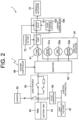
- FIG. 2 is a block diagram schematically illustrating a configuration of electric system and hydraulic system of the electric excavator 1.
- the electric excavator 1 includes the electric actuator 34, a pump motor 61, a charger 62, an inverter 63, a power drive unit (PDU) 64, a junction box 65, a direct current-direct current (DC-DC) converter 66, a lead battery 67, a system controller 68, the hydraulic pump 71, the hydraulic actuator 72, a hydraulic oil tank 73, and a hydraulic control device 100.
- the electric actuators 34 include the boom motor 31a, arm motor 32a, and bucket motor 33a described above.
- the hydraulic actuator 72 includes the traveling motor 22, blade cylinder 23b, and swivel motor 42 described above.
- the boom motor 31a, the arm motor 32a, and the bucket motor 33a are driven by electric power supplied from the battery unit 44 via the junction box 65 and the inverter 63.
- the boom motor 31a, the arm motor 32a, and the bucket motor 33a are constituted by electric motors such as synchronous motors or induction motors.
- the pump motor 61 is driven by electric power supplied from the battery unit 44 via the junction box 65 and the inverter 63.
- the pump motor 61 is constituted by an electric motor such as a synchronous motor or an induction motor.
- the charger 62 (also referred to as a power feeder) converts an alternating voltage supplied from an external power supply (not illustrated) into a direct voltage.
- the inverter 63 converts a direct voltage supplied from the battery unit 44 into an alternating voltage and supplies the alternating voltage to the pump motor 61 and the electric actuator 34.
- the alternating voltage is supplied from the inverter 63 to the pump motor 61 and the electric actuator 34 respectively on the basis of a rotation command output from the system controller 68.
- a plurality of inverters 63 may be provided in accordance with the supply destination of the alternating voltage.
- the PDU 64 is a battery control unit that controls an internal battery relay to control inputting and outputting of the battery unit 44.
- the junction box 65 includes a charger relay, an inverter relay, a fuse and the like. The voltage output from the abovementioned charger 62 is supplied to the battery unit 44 via the junction box 65 and the PDU 64. Further, the voltage output from the battery unit 44 is supplied to the inverter 63 via the PDU 64 and the junction box 65.
- the DC-DC converter 66 lowers a direct voltage of a high-voltage (300 V, for example) supplied from the battery unit 44 via the junction box 65 to a low voltage (12 V, for example).
- the direct voltage output from the DC-DC converter 66 is supplied to the system controller 68 or the like.
- the lead battery 67 outputs a low-voltage (12 V, for example) of a direct voltage.
- the output voltage from the lead battery 67 is supplied to, for example, the system controller 68 or the like as a control voltage, similarly to the output from the DC-DC converter 66.
- the lead battery 67 is charged with the direct voltage output from the DC-DC converter 66.
- the system controller 68 is constituted by an electronic control unit (ECU).
- the system controller 68 controls each part of the electric excavator 1 in response to a steering command from a remote steering device (not illustrated).
- a plurality of the hydraulic pumps 71 are connected to a rotary shaft (output shaft) of the pump motor 61.
- the plurality of hydraulic pumps 71 include a variable displacement pump and a fixed displacement pump.
- FIG. 2 illustrates only one hydraulic pump 71 as an example.
- Each hydraulic pump 71 is connected to the hydraulic oil tank 73 that contains (stores) hydraulic oil.
- the hydraulic oil pressure-fed from the hydraulic pump 71 includes high-pressure oil and low-pressure oil.
- the high-pressure oil is supplied to the hydraulic actuator 72 via a control valve 101 included in the hydraulic control device 100, and is used to drive the hydraulic actuator 72.
- the low-pressure oil is supplied to the control valve 101 via a flow passage portion 102 included in the hydraulic control device 100, and is used to control the control valve 101.
- the low-pressure oil is also referred to as pilot oil.
- pilot oil a configuration of the hydraulic control device 100 will be described.
- FIG. 3 is a plan view illustrating a configuration of the hydraulic control device 100.
- FIG. 4 is a block diagram schematically illustrating a configuration of the hydraulic control device 100.
- the hydraulic control device 100 is arranged in the upper swivel body 4.
- the hydraulic control device 100 is positioned on the front side of the pump motor 61 and the hydraulic pump 71, and on the left side of the hydraulic oil tank 73.
- the hydraulic control device 100 includes a plurality of control valves 101 and a flow passage portion 102.
- the control valve 101 controls the flow direction and flow rate of the hydraulic oil (high-pressure oil) supplied to the hydraulic actuator 72.
- the flow passage portion 102 is connected to the control valve 101.
- the pilot oil flows through the flow passage portion 102.
- a configuration including five control valves 101 is illustrated as an example, but the number of the control valves 101 is not limited thereto. For example, two or more control valves 101 may be included. The arrangement of the control valves 101 will be described below.
- the control valve 101 has a spool 101a consituted by a metallic cylindrical member, and a pair of solenoid valves 101b (a first solenoid valve 101b1 and a second solenoid valve 101b2).
- the solenoid valve 101b is also referred to as a drive valve that drives the control valve 101.
- an electric valve may be used as a drive valve.
- the spool 101a is driven by the pilot oil supplied from the first solenoid valve 101b1 and the second solenoid valve 101b2. That is, the solenoid valve 101b drives the spool 101a.
- the pilot oil supplied from the first solenoid valve 101b1 acts on one end surface of the spool 101a
- the pilot oil supplied from the second solenoid valve 101b2 acts on the other end surface of the spool 101a, and the spool 101a is thereby driven.
- the first solenoid valve 101b1 and the second solenoid valve 101b2 are each driven on the basis of a drive command from the system controller 68.
- the first solenoid valve 101b1 and the second solenoid valve 101b2 may be constituted by ON/OFF valves that can be switched between fully open and fully closed, but are preferably constituted by proportional valves whose opening amounts can be adjusted.
- the flow passage portion 102 includes a first piping portion 103 and a relay portion 104.
- the first piping portion 103 includes a first supply portion 103a and a first discharge portion 103b.
- the first supply portion 103a is constituted by a single hydraulic hose.
- the first supply portion 103a is connected to the hydraulic pump 71 and a first port P1 (see FIGs. 5 and 6 ) of a first supply block 107a, which will be described below.
- the first discharge portion 103b is connected to a second port P2 (see FIGs. 5 and 6 ) of a second discharge block 108b, which will be described below, and the hydraulic oil tank 73.
- the first discharge portion 103b includes a first discharge hose 103b1, a discharge joint portion 103b2, and a second discharge hose 103b3.
- Each of the first discharge hose 103b1 and the second discharge hose 103b3 is constituted by a hydraulic hose.
- the discharge joint portion 103b2 is consituted by a metal rod-shaped member which extends in the up-down direction and in which a flow passage is provided.
- the discharge joint portion 103b2 is connected to the first discharge hose 103b1 and the second discharge hose 103b3, and allows the first discharge hose 103b1 and the second discharge hose 103b3 to communicate with each other. Thus, a single flow passage is formed in the first discharge portion 103b.
- the relay portion 104 includes a relay member 105 and a second piping portion 106.
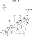
- the relay member 105 includes a block BL1 and a connector HC1.
- the block BL1 is consituted by a metal rectangular parallelepiped member.
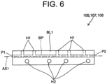
- a branch flow passage BP having a plurality of branches is formed inside the block BL1.
- a first port P1 and a second port P2 are provided on each side surface intersecting the longitudinal direction of the block BL1 (the direction of an axis AX1 along the longitudinal direction of the block BL1). Further, a flow hole H1 is provided in the upper surface of the block BL1.
- the interval between the flow holes H1 in the direction of the axis AX1 is set in accordance with the positions of a supply port and a discharge port (both not illustrated) for the pilot oil provided in each solenoid valve 101b.
- a screw hole H2 provided in the block BL1 will be described below.
- the connectors HC1 are respectively arranged at positions corresponding to the flow holes H1 of the block BL1. Via the connectors HC1, the hydraulic hose is attached to the block BL1.
- the relay member 105 includes a first relay block 107 and a second relay block 108.
- the first relay block 107 and the second relay block 108 have the same configuration as the relay member 105 described with reference to FIGs. 5 and 6 . Therefore, the first relay block 107 and the second relay block 108 have the same configuration.
- the first relay block 107 further includes a first supply block 107a and a second supply block 107b.
- the second relay block 108 further includes a first discharge block 108a and a second discharge block 108b.
- the first supply block 107a, the second supply block 107b, the first discharge block 108a, and the second discharge block 108b have the same configuration, and have the same configuration as that illustrated in FIGs. 5 and 6 . From the perspective of consituting the first supply block 107a, the second supply block 107b, the first discharge block 108a, and the second discharge block 108b by one type of member to reduce the number of types of members to be used, it is desirable that each first relay block 107 be identical to each second relay block 108 as in the present embodiment.
- the first supply block 107a and the second supply block 107b are connected by a first connection pipe 109.
- the first connection pipe 109 connects the second port P2 of the first supply block 107a and the second port P2 of the second supply block 107b.
- the first supply block 107a is positioned on the upstream side with respect to the first connection pipe 109, and the second supply block 107b is positioned on the downstream side.
- the first discharge block 108a and the second discharge block 108b are connected by a second connection pipe 110.
- the second connection pipe 110 connects the first port P1 of the first discharge block 108a and the first port P1 of the second discharge block 108b.
- the first discharge block 108a is positioned on the upstream side with respect to the second connection pipe 110, and the second discharge block 108b is positioned on the downstream side.
- Each of the first connection pipe 109 and the second connection pipe 110 is constituted by a hydraulic hose.
- the first port P1 of the second supply block 107b and the second port P2 of the first discharge block 108a are closed by plugs (not illustrated), respectively.
- the second piping portion 106 is provided corresponding to the first solenoid valve 101b1 and the second solenoid valve 101b2 of each of the control valves 101. Therefore, two second piping portions 106 are provided for one control valve 101. In addition, one of the second piping portions 106 is connected to the first solenoid valve 101b1. The other second piping portion 106 is connected to the second solenoid valve 101b2.
- the second piping portion 106 connected to each control valve 101 includes a second supply portion 106a and a second discharge portion 106b.
- the second supply portion 106a includes a first supply pipe 106a1 and a second supply pipe 106a2.
- the first supply pipe 106a1 connects the first supply block 107a and the first solenoid valve 101b1.
- the first supply pipe 106a1 is connected to the flow hole H1 (see FIG. 6 ) of the first supply block 107a via the connector HC1.
- the second supply pipe 106a2 connects the second supply block 107b and the second solenoid valve 101b2.
- the second supply pipe 106a2 is connected to the flow hole H1 of the second supply block 107b via the connector HC1.
- the second discharge portion 106b includes a first discharge pipe 106b1 and a second discharge pipe 106b2.
- the first discharge pipe 106b1 connects the first solenoid valve 101b1 and the first discharge block 108a.
- the first discharge pipe 106b1 is connected to the flow hole H1 of the first discharge block 108a via the connector HC1.
- the second discharge pipe 106b2 connects the second solenoid valve 101b2 and the second discharge block 108b.
- the second discharge pipe 106b is connected to the flow hole H1 of the second discharge block 108b via the connector HC1.
- each of the first supply pipe 106a1, the second supply pipe 106a2, the first discharge pipe 106b 1, and the second discharge pipe 106b2 is constituted by a hydraulic hose. Further, all of the first supply pipe 106a1, the second supply pipe 106a2, the first discharge pipe 106b1, and the second discharge pipe 106b2 are constituted by the same member. That is, the lengths of the members (hydraulic hoses) are the same between the first supply pipes 106a1, between the second supply pipes 106a2, between the first discharge pipes 106b1, and between the second discharge pipes 106b2.
- the lengths of the respective members are the same in the first supply pipe 106a1, the second supply pipe 106a2, the first discharge pipe 106b1, and the second discharge pipe 106b2. Thus, it is possible to prevent erroneous assembly at the time of assembly of each member.
- the pilot oil pressure-fed from the hydraulic pump 71 passes through the first supply portion 103a and flows into the first supply block 107a from the first port P1 (see FIG. 6 ).
- pilot oil flowing into the first supply block 107a is branched by an internal branch flow passage BP (see FIG. 6 ), passes through the flow hole H1 and the first supply pipe 106a1, and is respectively supplied to the first solenoid valves 101b1 of the respective control valves 101. Further, the remainder of the pilot oil flowing into the first supply block 107a is discharged from the first supply block 107a through the second port P2 (see FIG. 6 ), and then passes through the first connection pipe 109, and flows into the second supply block 107b from the second port P2.
- the remainder of the pilot oil flowing into the second supply block 107b is branched by the internal branch flow passage BP, and passes through flow hole H1 and the second supply pipe 106a2, and is supplied to the second solenoid valves 101b2 of the respective control valves 101. Then, when the first solenoid valve 101b1 and the second solenoid valve 101b2 are driven on the basis of the drive command from the system controller 68, the pilot oil acts on the spool 101a from the first solenoid valve 101b1 and the second solenoid valve 101b2, respectively, and the spool 101a is driven.
- the first supply block 107a and each first supply pipe 106a1 that constitute the relay portion 104 connect the first supply portion 103a and the first solenoid valve 101b1 of each control valve 101. Therefore, it can be said that the relay portion 104 connects the first piping portion 103 and the solenoid valve 101b in the flow passage on the pilot oil supply side.
- the pilot oil discharged from each first solenoid valve 101b1 flows into the first discharge block 108a from the flow hole H1 through the first discharge pipe 106b 1.
- the pilot oil discharged from the first solenoid valve 101b1 of each control valve 101 is merged by the internal branch flow passage BP.
- the pilot oil merged in the first discharge block 108a is discharged from the first port P1, passes through the second connection pipe 110, and flows into the second discharge block 108b from the first port P1.
- each second solenoid valve 101b2 flows into the second discharge block 108b from the flow hole H1 through the second discharge pipe 106b2.
- the pilot oil discharged from the second solenoid valve 101b2 of each control valve 101 is merged by the internal branch flow passage BP. Further, the pilot oil flowing in from the first discharge block 108b through the second connection pipe 110 also merges in the second discharge block 108a. Then, the pilot oil merged in the second discharge block 108b is discharged from the second port 108b of the second discharge block P2, passes through the first discharge portion 103b, and flows toward the hydraulic oil tank 73.
- the electric excavator 1 of the present embodiment includes the hydraulic control device 100 described above.
- the first piping portion 103 and the solenoid valves 101b included in the plurality of control valves 101 can communicate with each other via the relay portion 104 of the flow passage portion 102.
- the first supply portion 103a and the first solenoid valve 101b1 of each of the control valves 101 can communicate with each other via one first supply block 107a and a plurality of second supply portions 106a (first supply pipe 106a1).
- the flow passage on the side opposite to the first solenoid valve 101b1 with respect to the relay portion 104 that is, the flow passage connecting the relay portion 104 and the hydraulic pump 71 can be constituted by the first supply portion 103a that forms a single flow passage.
- the first discharge portion 103b and the second solenoid valve 101b2 of each of the control valves 101 can communicate with each other via a plurality of second discharge portions 106b (second discharge pipe 106b2) and one second discharge block 108b.
- the flow passage on the side opposite to the second solenoid valve 101b2 with respect to the relay portion 104 that is, the flow passage connecting the relay portion 104 and the hydraulic oil tank 73 can be constituted by the first discharge portion 103b that forms a single flow passage.
- the branched flow passage (branch flow passage BP) is provided inside the individual relay members 105 such as the first supply block 107a and the second discharge block 108b.
- the first piping portion 103 and each solenoid valve 101b can communicate with each other through the branched flow passage.
- the first supply portion 103a and each first solenoid valve 101b1 can communicate with each other via the first supply block 107a as the relay member 105.
- the first discharge portion 103b and each second solenoid valve 101b2 can communicate with each other via the second discharge block 108b as the relay member 105. From the perspective of implementing such communication, as in the present embodiment, it is desirable that the relay portion 104 have the relay member 105 having a flow passage which is branched inside.
- the relay portion 104 has the plurality of first supply pipes 106a1 in addition to the first supply block 107a as the relay member 105, and thus each of the plurality of first solenoid valves 101b1 and one first supply block 107a can be connected by each first supply pipe 106a1.
- the relay portion 104 has the plurality of second supply pipes 106a2 in addition to the second supply block 107b as the relay member 105, and thus each of the plurality of second solenoid valves 101b2 and one second supply block 107b can be connected by each second supply pipe 106a2.
- the relay portion 104 has the plurality of first discharge pipes 106b1 in addition to the first discharge block 108a as the relay member 105, and thus each of the plurality of first solenoid valves 101b 1 and one first discharge block 108a can be connected by each first discharge pipe 106b1.
- the relay portion 104 has the plurality of second discharge pipes 106b2 in addition to the second discharge block 108b as the relay member 105, and thus each of the plurality of second solenoid valves 101b2 and one second discharge block 108b can be connected by each second discharge pipe 106b2.
- the relay portion 104 desirably includes a plurality of second piping portions 106 that connect the respective solenoid valves 101b and the relay member 105.
- the plurality of second piping portions 106 include at least one of a plurality of first supply pipes 106a1, a plurality of second supply pipes 106a2, a plurality of first discharge pipes 106b1, and a plurality of second discharge pipes 106b2.
- the flow passage that flows on the side opposite to the first solenoid valve 101b1 with respect to the first supply block 107a is constituted by the first supply portion 103a that forms a single flow passage.
- the pipes on the upstream side of the first supply block 107a are concentrated in the first supply portion 103a, and the layout of the pipes on the pilot oil supply side becomes compact.
- the relay member 105 it is desirable that the relay member 105 have the first relay block 107 (particularly, the first supply block 107a) provided on the pilot oil supply side with respect to each solenoid valve 101b.
- the second solenoid valve 101b2 is positioned on the side opposite to the first solenoid valve 101b1 with respect to the spool 101a. That is, the second solenoid valve 101b2 is arranged away from the first solenoid valve 101b1.
- the first supply block 107a provided on the pilot oil supply side with respect to the first solenoid valve 101b1 and the second supply block 107b provided on the pilot oil supply side with respect to the second solenoid valve 101b2 are connected by the first connection pipe 109.
- the relay portion 104 include the plurality of first relay blocks 107 (the first supply block 107a and the second supply block 107b) and the first connection pipe 109 connecting the first relay blocks 107 to each other.
- the flow passage that flows on the side opposite to the second solenoid valve 101b2 with respect to the second discharge block 108b is constituted by the first discharge portion 103b that forms a single flow passage.
- the pipes on the downstream side of the second discharge block 108b are concentrated in the first discharge portion 103b, and the layout of the pipes on the pilot oil discharge side becomes compact.
- the relay member 105 it is desirable that the relay member 105 have the second relay block 108 (particularly, the second discharge block 108b) provided on the pilot oil discharge side with respect to each solenoid valve 101b.
- the layout of the pipes on the pilot oil discharge side be compact.
- the second solenoid valve 101b2 is arranged away from the first solenoid valve 101b1.
- the first discharge block 108a provided on the pilot oil discharge side with respect to the first solenoid valve 101b1 and the second discharge block 108b provided on the pilot oil discharge side with respect to the second solenoid valve 101b2 are connected by the second connection pipe 110.
- the pilot oil discharged from the first solenoid valve 101b1 and the second solenoid valve 101b2 arranged apart from each other can be collectively discharged from the second discharge block 108b while concentrating the pipes on the downstream side of the second discharge block 108b in the first discharge portion 103b.
- the relay portion 104 include the plurality of second relay blocks 108 (the first discharge block 108a and the second discharge block 108b) and the second connection pipe 110 connecting the second relay blocks 108 to each other.
- FIGs. 7 and 8 are a plan view and a left side view illustrating the arrangement of the control valve 101, the first supply block 107a, the second supply block 107b, the first discharge block 108a, and the second discharge block 108b.
- the first piping portion 103, the second piping portion 106, and the like are not illustrated for convenience.
- the plurality of control valves 101 are supported by the swivel frame 41 (see FIG. 8 ) via a control valve bracket 121 and a support plate 122.
- the respective control valves 101 are arranged side by side in one direction and integrally fastened by a rod (not illustrated) or the like.
- the control valves 101 fastened to each other are fastened to the control valve bracket 121 by a bolt B1 and a bolt B2 (see FIG. 8 ).
- the abovementioned one direction is a direction inclined at an arbitrary angle ⁇ with respect to the left-right direction when viewed from above (see FIG. 7 ).
- the angle ⁇ is an acute angle, but may be any angle.
- the angle ⁇ may be 0 degrees, 90 degrees, or another angle.
- the abovementioned one direction coincides with a longitudinal direction of the first relay block 107 and the second relay block 108, which will be described below.
- the control valve bracket 121 is positioned above the support plate 122 and supports the control valve 101 from below.
- the control valve bracket 121 is consituted by a metal plate-like member extending in the horizontal direction.
- the control valve bracket 121 is fastened to the support plate 122 by a bolt B3.
- the support plate 122 is a metal plate-like member extending in the horizontal direction, has an area larger than that of the control valve bracket 121 when viewed from above, and is arranged below the control valve bracket 121 so as to overlap therewith.
- the support plate 122 is fastened to the swivel frame 41 by a bolt B4. In this way, the control valve bracket 121 and the support plate 122 support the control valve 101 from below. That is, the control valve bracket 121 and the support plate 122 are support members that support the control valve 101 from below.
- the first supply block 107a is positioned obliquely rearward of the control valve 101
- the second supply block 107b is positioned obliquely forward of the control valve 101. Therefore, the control valve 101 is positioned between the respective first relay blocks 107 (the first supply block 107a and the second supply block 107b) in plan view.
- the axis AX1 (see FIG. 5 ) along the longitudinal direction of the first supply block 107a is positioned so as to intersect a drive axis AX2 of the spool 101a included in the control valve 101 at a substantially right angle in plan view.
- the axis AX1 along the longitudinal direction of the second supply block 107b is also positioned so as to intersect the drive axis AX2 of the spool 101a at a substantially right angle. That is, each first relay block 107 is arranged in such a manner that the longitudinal direction of each first relay block 107 intersects the drive axis AX2 of the spool 101a in plan view.
- the first discharge block 108a is positioned obliquely rearward of the first supply block 107a, and the second discharge block 108b is positioned obliquely forward of the second supply block 107b. Therefore, each first relay block 107 is positioned between the respective second relay blocks 108 (the first discharge block 108a and the second discharge block 108b) in plan view.
- the axis AX1 along the longitudinal direction of the first discharge block 108a is positioned so as to intersect the drive axis AX2 of the spool 101a at a substantially right angle in plan view.
- the axis AX1 along the longitudinal direction of the second discharge block 108b is also positioned so as to intersect the drive axis AX2 of the spool 101a at a substantially right angle. That is, each second relay block 108 is arranged in such a manner that the longitudinal direction of each second relay block 108 intersects the drive axis AX2 of the spool 101a in plan view.
- two first relay blocks 107 are arranged at positions sandwiching each of the control valves 101 in the direction of the drive axis AX2.
- two first relay blocks 108 are arranged at positions sandwiching the two second relay blocks 107 in the direction of the drive axis AX2.
- the first supply block 107a is arranged to be shifted from the first discharge block 108a in a direction in which the axis AX1 extends. That is, the first supply block 107a is arranged so as to be shifted from the first discharge block 108a in a direction intersecting the drive axis AX2 of the spool 101a. As a result, it is possible to avoid interference between the first supply pipe 106a1 connected to the first supply block 107a and the first discharge pipe 106b1 connected to the first discharge block 108a.
- the second supply block 107b is arranged to be shifted from the second discharge block 108b in a direction in which the axis AX1 extends. That is, the second supply block 107b is arranged so as to be shifted from the second discharge block 108b in a direction intersecting the drive axis AX2 of the spool 101a. As a result, it is possible to avoid interference between the second supply pipe 106a2 connected to the second supply block 107b and the second discharge pipe 106b2 connected to the second discharge block 108b.
- each first relay block 107 be arranged so as to be shifted in a direction intersecting the drive axis AX2 with respect to each of the second relay blocks 108 in plan view.
- the first supply block 107a and the second supply block 107b are supported by the support plate 122 via the first block bracket 123.
- the first block bracket 123 is provided for each of the first supply block 107a and the second supply block 107b.
- One first block bracket 123 is positioned from the side to the lower side of the first supply block 107a.
- the other first block brackets 123 is positioned from the side to the lower side of the second supply block 107b.
- Each first block bracket 123 is positioned above the support plate 122, and is formed by bending a lower portion of a metal plate-like member extending in the up-down direction toward the control valve 101.
- the first supply block 107a and the second supply block 107b are each fastened to a surface along the up-down direction of each first block bracket 123 by a bolt B5 (see FIG. 7 ).
- the bolt B5 is screwed into a screw hole H2 (see FIGs. 5 and 6 ) provided in the first supply block 107a and the second supply block 107b.
- the aforementioned screwing means that a member having a male screw and a member having a female screw are meshed with each other and connected to each other.
- the above screwing means that a bolt is turned thereby to join with a nut.
- a lower portion of the first block bracket 123 is fastened to the support plate 122 by a bolt B6.
- the first block bracket 123 is fixed above the support plate 122. Therefore, the first supply block 107a and the second supply block 107b are fixed to the support plate 122 via the first block bracket 123. That is, the support plate 122 is a support member that supports the first supply block 107a and the second supply block 107b from below.
- the first discharge block 108a and the second discharge block 108b are supported by the support plate 122 via a second block bracket 124.
- the second block bracket 124 is provided for each of the first discharge block 108a and the second discharge block 108b.
- One second block bracket 124 is positioned from the side to the lower side of the first discharge block 108a.
- the other second block bracket 124 is positioned from the side to the lower side of the second discharge block 108b.
- Each second block bracket 124 is positioned above the support plate 122.
- Each second block bracket 124 is formed by bending a lower portion of a metal plate-like member extending in the up-down direction toward the control valve 101.
- the second block bracket 124 is configured to have a lower height in the up-down direction than the first block bracket 123.
- the first discharge block 108a and the second discharge block 108b are each fastened to a surface along the up-down direction of each second block bracket 124 by a bolt B7.
- the bolt B7 is screwed into the screw hole H2 provided in the first discharge block 108a and the second discharge block 108b. Therefore, the first discharge block 108a and the second discharge block 108b are fixed to the second block bracket 124 configured to be lower than the first block bracket 123. That is, the first discharge block 108a and the second discharge block 108b are fixed at a position lower than the first supply block 107a and the second supply block 107b. In this way, the first supply block 107a and the second supply block 107b are arranged so as to be shifted in the up-down direction with respect to the first discharge block 108a and the second discharge block 108b.
- the first supply block 107a is arranged so as to be shifted in the up-down direction with respect to the first discharge block 108a, and the second block bracket 124 is thereby arranged below the first supply block 107a.
- the first supply block 107a and the first discharge block 108a are arranged close to each other in the direction of the drive axis AX2.
- the second supply block 107b is arranged so as to be shifted in the up-down direction with respect to the second discharge block 108b, and the second block bracket 124 is thereby arranged below the second supply block 107b.
- the second supply block 107b and the second discharge block 108b are arranged close to each other in the direction of the drive axis AX2.
- the first relay block 107 and the second relay block 108 are compactly arranged while effectively using the space below the first relay block 107 (the first supply block 107a and the second supply block 107b). From this perspective, as in the present embodiment, it is desirable that each first relay block 107 be arranged so as to be shifted in the up-down direction with respect to each second relay block 108.
- a lower portion of the second block bracket 124 is fastened to the support plate 122 by a bolt B8.
- the second block bracket 124 is fixed above the support plate 122. Therefore, the first discharge block 108a and the second discharge block 108b are fixed to the support plate 122 via the second block bracket 124. That is, the support plate 122 is a support member that supports the first discharge block 108a and the second discharge block 108b from below.
- FIG. 9 is a flowchart illustrating an attachment procedure of each member constituting the flow passage portion 102.
- the second block bracket 124 to which the second relay block 108 (the first discharge block 108a and the second discharge block 108b) is attached by the bolt B7 is attached to the support plate 122 by the bolt B8 (S1).
- the second relay block 108 is attached to the support plate 122 via the second block bracket 124.
- a member 125 (see FIG. 3 ) that supports a connector EC1 (see FIG. 3 ) of an electric wire extending from each solenoid valve 101b is attached to the second relay block 108 by a bolt B9 (see FIG. 3 ) before S1.
- the member 125 is attached with the use of the remaining screw hole H2 after the attachment of the second block bracket 124 among the screw holes H2 (see FIGs. 5 and 6 ) provided in the second relay block 108.
- the member 125 may be attached to the second block bracket 124 after S1.
- the first block bracket 123 to which the first relay block 107 (the first supply block 107a and the second supply block 107b) is attached by the bolt B5 is attached to the support plate 122 by the bolt B6 (S2).
- the piping member (hydraulic hose) constituting the first supply portion 103a included in the first piping portion 103 is attached to the first supply block 107a
- the piping member (hydraulic hose) constituting the first discharge portion 103b is attached to the second discharge block 108b (S3).
- first connection pipe 109 is attached to each first relay block 107
- second connection pipe 110 is attached to each second relay block 108 (S4).
- the piping member (hydraulic hose) constituting the second supply portion 106a included in the second piping portion 106 is attached to each first relay block 107 and each solenoid valve 101b
- the piping member (hydraulic hose) constituting the second discharge portion 106b is attached to each second relay block 108 and each solenoid valve 101b (S5).
- each control valve 101 and each relay member 105 are arranged (fixed) on one support plate 122, and the entire layout of each control valve 101 and each relay member 105 thereby becomes compact.
- the hydraulic control device 100 include a support member (the support plate 122) that supports each control valve 101, and support brackets (the first block bracket 123 and the second block bracket 124) that fix each relay member 105 to the support member.
- the flow passage portion 102 is mainly constituted by a hydraulic hose, but the flow passage portion 102 may use metallic piping (pipe) or the like instead of the hydraulic hose.
- a single flow passage may be formed in the first piping portion 103 by metallic piping, and the solenoid valve 101b and the relay member 105 may be connected by the second piping portion 106 constituted by a metallic pipe.
- the relay member 105 is constituted by a rectangular parallelepiped member in which a flow passage is formed, but the configuration of the relay member 105 is not limited to this.
- the relay member 105 may be constituted by metallic piping (pipe) having a flow hole and an attachment portion.
- the electric excavator 1 may be configured to drive the hydraulic pump 71 by using an engine instead of the pump motor 61.
- the electric excavator 1 may be configured to include a steering section on which an operator can steer the electric excavator 1.
- the electric excavator 1 has been described above as an example of a work machine, the work machine is not limited to the electric excavator 1, and may be a construction machine such as a hydraulic excavator or a wheel loader. In addition, the work machine may be an agricultural machine such as a combine harvester, or a tractor.
- the electric excavator 1 and the hydraulic control device 100 described in the present embodiment can also be expressed as a work machine and a hydraulic control device as illustrated in the following Supplementary Notes.
- a hydraulic control device comprising:
- a hydraulic control device in the hydraulic control device according to Supplementary Note (1), wherein the relay portion includes a relay member having a flow passage branched therein.
- a hydraulic control device in the hydraulic control device according to Supplementary Note (2), wherein the relay portion includes a plurality of second piping portions that connect the each drive valve and the relay member.
- a hydraulic control device in the hydraulic control device according to Supplementary Note (2) or (3), wherein the relay member includes first relay blocks provided on a supply side of the pilot oil with respect to the each drive valve.
- a hydraulic control device in the hydraulic control device according to Supplementary Note (4), the relay portion comprising:
- a hydraulic control device in the hydraulic control device according to Supplementary Note (5), wherein the relay member includes second relay blocks provided on a discharge side of the pilot oil with respect to the each drive valve.
- a hydraulic control device in the hydraulic control device according to Supplementary Note (6), the relay portion comprising:
- a hydraulic control device in the hydraulic control device according to Supplementary Note (8), wherein each of the first relay blocks is arranged to be shifted in a direction intersecting the drive axis with respect to each of the second relay blocks in plan view.
- a hydraulic control device in the hydraulic control device according to Supplementary Note (8) or (9), wherein each of the first relay blocks is arranged to be shifted in an up-down direction with respect to each of the second relay blocks.
- a hydraulic control device in the hydraulic control device according to any of Supplementary Notes (6) to (10), wherein each of the first relay blocks is the same as each of the second relay blocks.
- a hydraulic control device in the hydraulic control device according to any of Supplementary Notes (2) to (11), further comprising:
- the present invention is applicable to work machines such as a construction machine and an agricultural machine, for example.
Landscapes
- Engineering & Computer Science (AREA)
- General Engineering & Computer Science (AREA)
- Physics & Mathematics (AREA)
- Fluid Mechanics (AREA)
- Mechanical Engineering (AREA)
- Civil Engineering (AREA)
- Mining & Mineral Resources (AREA)
- Structural Engineering (AREA)
- Fluid-Pressure Circuits (AREA)
- Operation Control Of Excavators (AREA)
- Branch Pipes, Bends, And The Like (AREA)
- Valve Housings (AREA)
- Multiple-Way Valves (AREA)
Abstract
[Problem] To provide a hydraulic control device capable of driving each control valve by electric control while compactly constituting the piping of pilot oil, and a work machine including the hydraulic control device.[Solution] The hydraulic control device includes a plurality of control valves and a flow passage portion which is connected to each of the control valves and through which pilot oil flows. Each of the control valves includes a drive valve that drives each of the control valves, and the flow passage portion includes a first piping portion through which the pilot oil flows and a relay portion that connects each drive valve and the first piping portion.
Description
- The present invention relates to a hydraulic control device and a work machine including the same.
- A hydraulic control device having a plurality of hydraulic pilot-type control valves is known as a related art (for example, see Patent Document 1).
- Patent Document 1:
Japanese Patent No. 4151597 - In recent years, a configuration in which each control valve is driven under electrical control has been considered. In doing so, in a small-sized work machine on which a hydraulic control device is mounted, it is desired that the piping of the pilot oil connected to each control valve is also compactly configured in consideration of an arrangement space of each member. In this regard,
Patent Document 1 does not consider at all that each control valve is driven by electrical control while compactly constituting the piping of pilot oil. - The present invention has been made in order to solve the above problem, and it is an object of the present invention to provide a hydraulic control device capable of driving each control valve by electric control while compactly constituting the piping of pilot oil, and a work machine including the hydraulic control device.
- A hydraulic control device according to one aspect of the present invention includes a plurality of control valves, and a flow passage portion which is connected to each of the control valves and through which pilot oil flows. Each of the control valves includes a drive valve that drives each of the control valves, and the flow passage portion includes a first piping portion through which the pilot oil flows, and a relay portion that connects each drive valve and the first piping portion.
- According to the above configuration, it is possible to drive each control valve by electrical control while compactly constituting the piping (flow passage portion) of the pilot oil connected to each control valve.
-
-
FIG. 1 is a left side view illustrating a schematic configuration of an electric excavator which is an example of a work machine according to an embodiment of the present invention. -
FIG. 2 is a block diagram schematically illustrating a configuration of electric system and hydraulic system of the electric excavator. -
FIG. 3 is a plan view illustrating a configuration of a hydraulic control device included in the electric excavator. -
FIG. 4 is a block diagram schematically illustrating a configuration of the hydraulic control device. -
FIG. 5 is a perspective view illustrating a configuration of a relay member of the hydraulic control device. -
FIG. 6 is a side view illustrating a configuration of the relay member. -
FIG. 7 is a plan view illustrating an arrangement of the relay member. -
FIG. 8 is a left side view illustrating an arrangement of the relay member. -
FIG. 9 is a flowchart illustrating an attachment procedure of a flow passage portion of the hydraulic control device. - The following is a description of an embodiment of the present invention based on the drawings.
-
FIG. 1 is a left side view illustrating a schematic configuration of anelectric excavator 1 which is an example of a work machine according to an embodiment of the present invention. Theelectric excavator 1 includes alower traveling body 2, a work implement 3, and an upperswivel body 4. - Here, directions are defined as follows. One side in one direction when the lower
traveling body 2 travels straight along the one direction is referred to as "front", and the other side is referred to as "rear". For example, in a direction in which the lower travelingbody 2 travels straight along one direction, a side opposite to a side on which a travelingmotor 22 is arranged (a side on which asoil removal unit 23 is arranged) is referred to as "front", and a side on which the travelingmotor 22 is arranged is referred to as "rear". The front-rear direction of the upperswivel body 4 matches the front-rear direction of the lower travelingbody 2 in a state where the upperswivel body 4 is in a non-swivel state (swivel angle of 0 degrees) with respect to the lower travelingbody 2. In addition, when theelectric excavator 1 is viewed from the rear, the left side is referred to as "left", and the right side is referred to as "right". Further, a gravity direction perpendicular to the front-rear direction and the left-right direction is defined as an up-down direction, with an upstream side of the gravity direction defined as "up" and a downstream side defined as "down". In the drawings, theelectric excavator 1 is illustrated in a state where the upperswivel body 4 does not swivel with respect to the lowertraveling body 2. Furthermore, in the drawings, if necessary, forward is denoted by a symbol "F", likewise, backward by "B", rightward by "R", leftward by "L", upward by "U", and downward by "D". - The
lower traveling body 2 includes a pair of left andright crawlers 21, a pair of left andright traveling motors 22, thesoil removal unit 23, and a swivel bearing 24. Each of thetraveling motors 22 is constituted by hydraulic motor. The left and right travelingmotors 22 drive the left andright crawlers 21, respectively, and thus theelectric excavator 1 can be moved forward and rearward. Thesoil removal unit 23 for performing soil removal work and ground leveling work is provided in front of the lower travelingbody 2, and includes ablade 23a and ablade cylinder 23b. Theblade cylinder 23b is a hydraulic cylinder to rotate theblade 23a. The swivel bearing 24 is arranged near the center of the upper portion of the lower travelingbody 2 and supports the upperswivel body 4 in a swivelable manner. - The
work implement 3 includes aboom 31, anarm 32, and abucket 33. Theboom 31, thearm 32, and thebucket 33 can be independently driven, thereby enabling to perform excavation work of earth, sand, and the like. - The
boom 31 is rotated by aboom motor 31a. Theboom motor 31a is provided at a base end portion of theboom 31 and is rotationally driven. Thearm 32 is rotated by anarm motor 32a. Thearm motor 32a is provided at a base end portion of thearm 32 and is rotationally driven. Thebucket 33 is rotated by abucket motor 33a. Thebucket motor 33a is provided at a base end portion of thebucket 33 and is rotationally driven. Theboom motor 31a, thearm motor 32a, and thebucket motor 33a are constituted by electric motors that are driven to rotate by receiving a supply of electric power. A device that is driven by receiving supply of electric power is also referred to as an electric actuator 34 (seeFIG. 2 ). The electric motors are included in theelectric actuator 34. - The upper
swivel body 4 is positioned above the lower travelingbody 2 and is swivelably provided with respect to the lower travelingbody 2 via the swivel bearing 24. The upperswivel body 4 is provided with aswivel frame 41, aswivel motor 42, anengine room 43, and the like. By driving of theswivel motor 42 that is a hydraulic motor, the upperswivel body 4 swivels with respect to the lower travelingbody 2 via the swivel bearing 24. - A pump motor 61 (see
FIG. 2 ) and a hydraulic pump 71 (seeFIG. 2 ) are arranged in the upperswivel body 4. Thehydraulic pump 71 is driven by thepump motor 61, and supplies hydraulic oil (pressure oil) to hydraulic motors (for example, the left andright traveling motors 22 and the swivel motor 42) and hydraulic cylinders (for example, theblade cylinder 23b). The hydraulic motors and the hydraulic cylinders that are driven with the hydraulic oil supplied from thehydraulic pump 71 are collectively referred to ashydraulic actuators 72. - A
battery unit 44 is arranged in the upperswivel body 4. Thebattery unit 44 is constituted by, for example, a lithium ion battery, and stores electric power for driving thepump motor 61 and the electric actuators 34 (for example, theboom motor 31a) illustrated inFIG. 2 . Thebattery unit 44 may be constituted by a plurality of battery cells as a unit or may be constituted by a single battery cell. Further, theupper swivel body 4 is provided with a power supply port (not illustrated). Thebattery unit 44 can be charged by connecting the power supply port to an external power supply (not illustrated). - The
electric excavator 1 may be configured to include only thehydraulic actuator 72 as the actuator. For example, theboom 31, thearm 32, and thebucket 33 may be driven by a hydraulic cylinder. - Next, a configuration of electric system and hydraulic system of the
electric excavator 1 will be described.FIG. 2 is a block diagram schematically illustrating a configuration of electric system and hydraulic system of theelectric excavator 1. Theelectric excavator 1 includes theelectric actuator 34, apump motor 61, acharger 62, aninverter 63, a power drive unit (PDU) 64, ajunction box 65, a direct current-direct current (DC-DC)converter 66, alead battery 67, asystem controller 68, thehydraulic pump 71, thehydraulic actuator 72, ahydraulic oil tank 73, and ahydraulic control device 100. Theelectric actuators 34 include theboom motor 31a,arm motor 32a, andbucket motor 33a described above. Thehydraulic actuator 72 includes the travelingmotor 22,blade cylinder 23b, and swivelmotor 42 described above. - The
boom motor 31a, thearm motor 32a, and thebucket motor 33a are driven by electric power supplied from thebattery unit 44 via thejunction box 65 and theinverter 63. Theboom motor 31a, thearm motor 32a, and thebucket motor 33a are constituted by electric motors such as synchronous motors or induction motors. - The
pump motor 61 is driven by electric power supplied from thebattery unit 44 via thejunction box 65 and theinverter 63. Thepump motor 61 is constituted by an electric motor such as a synchronous motor or an induction motor. - The charger 62 (also referred to as a power feeder) converts an alternating voltage supplied from an external power supply (not illustrated) into a direct voltage. The
inverter 63 converts a direct voltage supplied from thebattery unit 44 into an alternating voltage and supplies the alternating voltage to thepump motor 61 and theelectric actuator 34. Thus, thepump motor 61 and theelectric actuator 34 are driven. The alternating voltage is supplied from theinverter 63 to thepump motor 61 and theelectric actuator 34 respectively on the basis of a rotation command output from thesystem controller 68. A plurality ofinverters 63 may be provided in accordance with the supply destination of the alternating voltage. - The
PDU 64 is a battery control unit that controls an internal battery relay to control inputting and outputting of thebattery unit 44. Thejunction box 65 includes a charger relay, an inverter relay, a fuse and the like. The voltage output from theabovementioned charger 62 is supplied to thebattery unit 44 via thejunction box 65 and thePDU 64. Further, the voltage output from thebattery unit 44 is supplied to theinverter 63 via thePDU 64 and thejunction box 65. - The DC-
DC converter 66 lowers a direct voltage of a high-voltage (300 V, for example) supplied from thebattery unit 44 via thejunction box 65 to a low voltage (12 V, for example). The direct voltage output from the DC-DC converter 66 is supplied to thesystem controller 68 or the like. - The
lead battery 67 outputs a low-voltage (12 V, for example) of a direct voltage. The output voltage from thelead battery 67 is supplied to, for example, thesystem controller 68 or the like as a control voltage, similarly to the output from the DC-DC converter 66. Thelead battery 67 is charged with the direct voltage output from the DC-DC converter 66. - The
system controller 68 is constituted by an electronic control unit (ECU). Thesystem controller 68 controls each part of theelectric excavator 1 in response to a steering command from a remote steering device (not illustrated). - A plurality of the
hydraulic pumps 71 are connected to a rotary shaft (output shaft) of thepump motor 61. The plurality ofhydraulic pumps 71 include a variable displacement pump and a fixed displacement pump.FIG. 2 illustrates only onehydraulic pump 71 as an example. Eachhydraulic pump 71 is connected to thehydraulic oil tank 73 that contains (stores) hydraulic oil. When thehydraulic pump 71 is driven by thepump motor 61, the hydraulic oil in thehydraulic oil tank 73 is pressure-fed. The hydraulic oil pressure-fed from thehydraulic pump 71 includes high-pressure oil and low-pressure oil. The high-pressure oil is supplied to thehydraulic actuator 72 via acontrol valve 101 included in thehydraulic control device 100, and is used to drive thehydraulic actuator 72. The low-pressure oil is supplied to thecontrol valve 101 via aflow passage portion 102 included in thehydraulic control device 100, and is used to control thecontrol valve 101. The low-pressure oil is also referred to as pilot oil. Hereinafter, a configuration of thehydraulic control device 100 will be described. -
FIG. 3 is a plan view illustrating a configuration of thehydraulic control device 100.FIG. 4 is a block diagram schematically illustrating a configuration of thehydraulic control device 100. - As illustrated in
FIG. 3 , thehydraulic control device 100 is arranged in theupper swivel body 4. Thehydraulic control device 100 is positioned on the front side of thepump motor 61 and thehydraulic pump 71, and on the left side of thehydraulic oil tank 73. Thehydraulic control device 100 includes a plurality ofcontrol valves 101 and aflow passage portion 102. Thecontrol valve 101 controls the flow direction and flow rate of the hydraulic oil (high-pressure oil) supplied to thehydraulic actuator 72. Theflow passage portion 102 is connected to thecontrol valve 101. The pilot oil flows through theflow passage portion 102. InFIG. 3 and subsequent drawings, a configuration including fivecontrol valves 101 is illustrated as an example, but the number of thecontrol valves 101 is not limited thereto. For example, two ormore control valves 101 may be included. The arrangement of thecontrol valves 101 will be described below. - As illustrated in
FIG. 4 , thecontrol valve 101 has aspool 101a consituted by a metallic cylindrical member, and a pair of solenoid valves 101b (a first solenoid valve 101b1 and a second solenoid valve 101b2). The solenoid valve 101b is also referred to as a drive valve that drives thecontrol valve 101. Instead of the solenoid valve 101b, an electric valve may be used as a drive valve. Thespool 101a is driven by the pilot oil supplied from the first solenoid valve 101b1 and the second solenoid valve 101b2. That is, the solenoid valve 101b drives thespool 101a. For example, the pilot oil supplied from the first solenoid valve 101b1 acts on one end surface of thespool 101a, and the pilot oil supplied from the second solenoid valve 101b2 acts on the other end surface of thespool 101a, and thespool 101a is thereby driven. - When the
spool 101a is driven, the flow passage through which the high-pressure oil supplied to thehydraulic actuator 72 flows is switched, or the opening amount of the flow passage is adjusted. As a result, the flow direction and flow rate of the high-pressure oil supplied to thehydraulic actuator 72 are adjusted, and thehydraulic actuator 72 is driven. - The first solenoid valve 101b1 and the second solenoid valve 101b2 are each driven on the basis of a drive command from the
system controller 68. The first solenoid valve 101b1 and the second solenoid valve 101b2 may be constituted by ON/OFF valves that can be switched between fully open and fully closed, but are preferably constituted by proportional valves whose opening amounts can be adjusted. - As illustrated in
FIG. 3 , theflow passage portion 102 includes afirst piping portion 103 and arelay portion 104. Thefirst piping portion 103 includes afirst supply portion 103a and afirst discharge portion 103b. Thefirst supply portion 103a is constituted by a single hydraulic hose. Thefirst supply portion 103a is connected to thehydraulic pump 71 and a first port P1 (seeFIGs. 5 and6 ) of afirst supply block 107a, which will be described below. - The
first discharge portion 103b is connected to a second port P2 (seeFIGs. 5 and6 ) of asecond discharge block 108b, which will be described below, and thehydraulic oil tank 73. Thefirst discharge portion 103b includes a first discharge hose 103b1, a discharge joint portion 103b2, and a second discharge hose 103b3. Each of the first discharge hose 103b1 and the second discharge hose 103b3 is constituted by a hydraulic hose. The discharge joint portion 103b2 is consituted by a metal rod-shaped member which extends in the up-down direction and in which a flow passage is provided. The discharge joint portion 103b2 is connected to the first discharge hose 103b1 and the second discharge hose 103b3, and allows the first discharge hose 103b1 and the second discharge hose 103b3 to communicate with each other. Thus, a single flow passage is formed in thefirst discharge portion 103b. - The
relay portion 104 includes arelay member 105 and asecond piping portion 106. As illustrated inFIG. 5 , therelay member 105 includes a block BL1 and a connector HC1. The block BL1 is consituted by a metal rectangular parallelepiped member. As illustrated inFIG. 6 , a branch flow passage BP having a plurality of branches is formed inside the block BL1. A first port P1 and a second port P2 are provided on each side surface intersecting the longitudinal direction of the block BL1 (the direction of an axis AX1 along the longitudinal direction of the block BL1). Further, a flow hole H1 is provided in the upper surface of the block BL1. The interval between the flow holes H1 in the direction of the axis AX1 is set in accordance with the positions of a supply port and a discharge port (both not illustrated) for the pilot oil provided in each solenoid valve 101b. A screw hole H2 provided in the block BL1 will be described below. - The connectors HC1 are respectively arranged at positions corresponding to the flow holes H1 of the block BL1. Via the connectors HC1, the hydraulic hose is attached to the block BL1.
- As illustrated in
FIG. 3 , therelay member 105 includes afirst relay block 107 and asecond relay block 108. Thefirst relay block 107 and thesecond relay block 108 have the same configuration as therelay member 105 described with reference toFIGs. 5 and6 . Therefore, thefirst relay block 107 and thesecond relay block 108 have the same configuration. - The
first relay block 107 further includes afirst supply block 107a and asecond supply block 107b. Thesecond relay block 108 further includes afirst discharge block 108a and asecond discharge block 108b. Thefirst supply block 107a, thesecond supply block 107b, thefirst discharge block 108a, and thesecond discharge block 108b have the same configuration, and have the same configuration as that illustrated inFIGs. 5 and6 . From the perspective of consituting thefirst supply block 107a, thesecond supply block 107b, thefirst discharge block 108a, and thesecond discharge block 108b by one type of member to reduce the number of types of members to be used, it is desirable that eachfirst relay block 107 be identical to eachsecond relay block 108 as in the present embodiment. - The
first supply block 107a and thesecond supply block 107b are connected by afirst connection pipe 109. In particular, thefirst connection pipe 109 connects the second port P2 of thefirst supply block 107a and the second port P2 of thesecond supply block 107b. Thefirst supply block 107a is positioned on the upstream side with respect to thefirst connection pipe 109, and thesecond supply block 107b is positioned on the downstream side. - The
first discharge block 108a and thesecond discharge block 108b are connected by asecond connection pipe 110. In particular, thesecond connection pipe 110 connects the first port P1 of thefirst discharge block 108a and the first port P1 of thesecond discharge block 108b. Thefirst discharge block 108a is positioned on the upstream side with respect to thesecond connection pipe 110, and thesecond discharge block 108b is positioned on the downstream side. Each of thefirst connection pipe 109 and thesecond connection pipe 110 is constituted by a hydraulic hose. The first port P1 of thesecond supply block 107b and the second port P2 of thefirst discharge block 108a are closed by plugs (not illustrated), respectively. - As illustrated in
FIG. 4 , thesecond piping portion 106 is provided corresponding to the first solenoid valve 101b1 and the second solenoid valve 101b2 of each of thecontrol valves 101. Therefore, twosecond piping portions 106 are provided for onecontrol valve 101. In addition, one of thesecond piping portions 106 is connected to the first solenoid valve 101b1. The othersecond piping portion 106 is connected to the second solenoid valve 101b2. - The
second piping portion 106 connected to eachcontrol valve 101 includes asecond supply portion 106a and asecond discharge portion 106b. Thesecond supply portion 106a includes a first supply pipe 106a1 and a second supply pipe 106a2. The first supply pipe 106a1 connects thefirst supply block 107a and the first solenoid valve 101b1. In particular, the first supply pipe 106a1 is connected to the flow hole H1 (seeFIG. 6 ) of thefirst supply block 107a via the connector HC1. The second supply pipe 106a2 connects thesecond supply block 107b and the second solenoid valve 101b2. In particular, the second supply pipe 106a2 is connected to the flow hole H1 of thesecond supply block 107b via the connector HC1. - The
second discharge portion 106b includes a first discharge pipe 106b1 and a second discharge pipe 106b2. The first discharge pipe 106b1 connects the first solenoid valve 101b1 and thefirst discharge block 108a. In particular, the first discharge pipe 106b1 is connected to the flow hole H1 of thefirst discharge block 108a via the connector HC1. The second discharge pipe 106b2 connects the second solenoid valve 101b2 and thesecond discharge block 108b. In particular, thesecond discharge pipe 106b is connected to the flow hole H1 of thesecond discharge block 108b via the connector HC1. - As illustrated in
FIG. 3 , each of the first supply pipe 106a1, the second supply pipe 106a2, thefirst 1, and the second discharge pipe 106b2 is constituted by a hydraulic hose. Further, all of the first supply pipe 106a1, the second supply pipe 106a2, the first discharge pipe 106b1, and the second discharge pipe 106b2 are constituted by the same member. That is, the lengths of the members (hydraulic hoses) are the same between the first supply pipes 106a1, between the second supply pipes 106a2, between the first discharge pipes 106b1, and between the second discharge pipes 106b2. Furthermore, the lengths of the respective members are the same in the first supply pipe 106a1, the second supply pipe 106a2, the first discharge pipe 106b1, and the second discharge pipe 106b2. Thus, it is possible to prevent erroneous assembly at the time of assembly of each member.discharge pipe 106b - Here, a series of flows of the pilot oil will be described with reference to
FIG. 4 . First, the supply of the pilot oil will be described. The pilot oil pressure-fed from thehydraulic pump 71 passes through thefirst supply portion 103a and flows into thefirst supply block 107a from the first port P1 (seeFIG. 6 ). - Some of the pilot oil flowing into the
first supply block 107a is branched by an internal branch flow passage BP (seeFIG. 6 ), passes through the flow hole H1 and the first supply pipe 106a1, and is respectively supplied to the first solenoid valves 101b1 of therespective control valves 101. Further, the remainder of the pilot oil flowing into thefirst supply block 107a is discharged from thefirst supply block 107a through the second port P2 (seeFIG. 6 ), and then passes through thefirst connection pipe 109, and flows into thesecond supply block 107b from the second port P2. - The remainder of the pilot oil flowing into the
second supply block 107b is branched by the internal branch flow passage BP, and passes through flow hole H1 and the second supply pipe 106a2, and is supplied to the second solenoid valves 101b2 of therespective control valves 101. Then, when the first solenoid valve 101b1 and the second solenoid valve 101b2 are driven on the basis of the drive command from thesystem controller 68, the pilot oil acts on thespool 101a from the first solenoid valve 101b1 and the second solenoid valve 101b2, respectively, and thespool 101a is driven. - From the above, it can be seen that, in the flow passage on the pilot oil supply side with respect to each
control valve 101, thefirst supply block 107a and each first supply pipe 106a1 that constitute therelay portion 104 connect thefirst supply portion 103a and the first solenoid valve 101b1 of eachcontrol valve 101. Therefore, it can be said that therelay portion 104 connects thefirst piping portion 103 and the solenoid valve 101b in the flow passage on the pilot oil supply side. - Next, the discharge of the pilot oil will be described. The pilot oil discharged from each first solenoid valve 101b1 flows into the
first discharge block 108a from the flow hole H1 through thefirst 1. In thedischarge pipe 106bfirst discharge block 108a, the pilot oil discharged from the first solenoid valve 101b1 of eachcontrol valve 101 is merged by the internal branch flow passage BP. The pilot oil merged in thefirst discharge block 108a is discharged from the first port P1, passes through thesecond connection pipe 110, and flows into thesecond discharge block 108b from the first port P1. - The pilot oil discharged from each second solenoid valve 101b2 flows into the
second discharge block 108b from the flow hole H1 through the second discharge pipe 106b2. In thesecond discharge block 108b, the pilot oil discharged from the second solenoid valve 101b2 of eachcontrol valve 101 is merged by the internal branch flow passage BP. Further, the pilot oil flowing in from thefirst discharge block 108b through thesecond connection pipe 110 also merges in thesecond discharge block 108a. Then, the pilot oil merged in thesecond discharge block 108b is discharged from thesecond port 108b of the second discharge block P2, passes through thefirst discharge portion 103b, and flows toward thehydraulic oil tank 73. - From the above, it can be seen that, in the flow passage on the pilot oil discharge side with respect to each
control valve 101, thesecond discharge block 108b and each second discharge pipe 106b2 that constitute therelay portion 104 connect thefirst discharge portion 103b and the second solenoid valve 101b2 of eachcontrol valve 101. Therefore, it can be said that therelay portion 104 connects thefirst piping portion 103 and the solenoid valve 101b also in the flow passage on the pilot oil discharge side. - In this way, the
electric excavator 1 of the present embodiment includes thehydraulic control device 100 described above. According to this configuration, thefirst piping portion 103 and the solenoid valves 101b included in the plurality ofcontrol valves 101 can communicate with each other via therelay portion 104 of theflow passage portion 102. For example, on the pilot oil supply side with respect to thecontrol valve 101, thefirst supply portion 103a and the first solenoid valve 101b1 of each of thecontrol valves 101 can communicate with each other via onefirst supply block 107a and a plurality ofsecond supply portions 106a (first supply pipe 106a1). Thus, the flow passage on the side opposite to the first solenoid valve 101b1 with respect to therelay portion 104, that is, the flow passage connecting therelay portion 104 and thehydraulic pump 71 can be constituted by thefirst supply portion 103a that forms a single flow passage. - Further, on the pilot oil discharge side with respect to the
control valve 101, thefirst discharge portion 103b and the second solenoid valve 101b2 of each of thecontrol valves 101 can communicate with each other via a plurality ofsecond discharge portions 106b (second discharge pipe 106b2) and onesecond discharge block 108b. Thus, the flow passage on the side opposite to the second solenoid valve 101b2 with respect to therelay portion 104, that is, the flow passage connecting therelay portion 104 and thehydraulic oil tank 73 can be constituted by thefirst discharge portion 103b that forms a single flow passage. - Therefore, it is possible to drive the
spool 101a included in thecontrol valve 101 by electrical control by each solenoid valve 101b while compactly constituting the piping of the pilot oil connected to each solenoid valve 101b. - As illustrated in
FIG. 6 , the branched flow passage (branch flow passage BP) is provided inside theindividual relay members 105 such as thefirst supply block 107a and thesecond discharge block 108b. As described above, thefirst piping portion 103 and each solenoid valve 101b can communicate with each other through the branched flow passage. To be specific, thefirst supply portion 103a and each first solenoid valve 101b1 can communicate with each other via thefirst supply block 107a as therelay member 105. Similarly, thefirst discharge portion 103b and each second solenoid valve 101b2 can communicate with each other via thesecond discharge block 108b as therelay member 105. From the perspective of implementing such communication, as in the present embodiment, it is desirable that therelay portion 104 have therelay member 105 having a flow passage which is branched inside. - The
relay portion 104 has the plurality of first supply pipes 106a1 in addition to thefirst supply block 107a as therelay member 105, and thus each of the plurality of first solenoid valves 101b1 and onefirst supply block 107a can be connected by each first supply pipe 106a1. Therelay portion 104 has the plurality of second supply pipes 106a2 in addition to thesecond supply block 107b as therelay member 105, and thus each of the plurality of second solenoid valves 101b2 and onesecond supply block 107b can be connected by each second supply pipe 106a2. - The
relay portion 104 has the plurality of first discharge pipes 106b1 in addition to thefirst discharge block 108a as therelay member 105, and thus each of the plurality of firstsolenoid valves 101b 1 and onefirst discharge block 108a can be connected by each first discharge pipe 106b1. Therelay portion 104 has the plurality of second discharge pipes 106b2 in addition to thesecond discharge block 108b as therelay member 105, and thus each of the plurality of second solenoid valves 101b2 and onesecond discharge block 108b can be connected by each second discharge pipe 106b2. - Therefore, from the perspective of reliably connecting the plurality of solenoid valves 101b and the
relay member 105, it can be said that therelay portion 104 desirably includes a plurality ofsecond piping portions 106 that connect the respective solenoid valves 101b and therelay member 105. The plurality ofsecond piping portions 106 include at least one of a plurality of first supply pipes 106a1, a plurality of second supply pipes 106a2, a plurality of first discharge pipes 106b1, and a plurality of second discharge pipes 106b2. - As described above, by providing the
first supply block 107a on the pilot oil supply side, the flow passage that flows on the side opposite to the first solenoid valve 101b1 with respect to thefirst supply block 107a is constituted by thefirst supply portion 103a that forms a single flow passage. As a result, the pipes on the upstream side of thefirst supply block 107a are concentrated in thefirst supply portion 103a, and the layout of the pipes on the pilot oil supply side becomes compact. From this perspective, as in the present embodiment, it is desirable that therelay member 105 have the first relay block 107 (particularly, thefirst supply block 107a) provided on the pilot oil supply side with respect to each solenoid valve 101b. - Even in a case where the pair of solenoid valves 101b included in each of the
control valves 101 are arranged apart from each other, it is desirable that the layout of the pipes on the pilot oil supply side be compact. For example, the second solenoid valve 101b2 is positioned on the side opposite to the first solenoid valve 101b1 with respect to thespool 101a. That is, the second solenoid valve 101b2 is arranged away from the first solenoid valve 101b1. Thefirst supply block 107a provided on the pilot oil supply side with respect to the first solenoid valve 101b1 and thesecond supply block 107b provided on the pilot oil supply side with respect to the second solenoid valve 101b2 are connected by thefirst connection pipe 109. Thus, it is possible to supply the pilot oil to the first solenoid valve 101b1 and the second solenoid valve 101b2 arranged apart from each other while concentrating the pipes on the upstream side of thefirst supply block 107a in thefirst supply portion 103a. From this perspective, as in the present embodiment, it is desirable that therelay portion 104 include the plurality of first relay blocks 107 (thefirst supply block 107a and thesecond supply block 107b) and thefirst connection pipe 109 connecting the first relay blocks 107 to each other. - As described above, by providing the
second discharge block 108b on the pilot oil discharge side, the flow passage that flows on the side opposite to the second solenoid valve 101b2 with respect to thesecond discharge block 108b is constituted by thefirst discharge portion 103b that forms a single flow passage. As a result, the pipes on the downstream side of thesecond discharge block 108b are concentrated in thefirst discharge portion 103b, and the layout of the pipes on the pilot oil discharge side becomes compact. From this perspective, as in the present embodiment, it is desirable that therelay member 105 have the second relay block 108 (particularly, thesecond discharge block 108b) provided on the pilot oil discharge side with respect to each solenoid valve 101b. - Even in a case where the pair of solenoid valves 101b included in each of the
control valves 101 are arranged apart from each other, it is desirable that the layout of the pipes on the pilot oil discharge side be compact. For example, as described above, the second solenoid valve 101b2 is arranged away from the first solenoid valve 101b1. Thefirst discharge block 108a provided on the pilot oil discharge side with respect to the first solenoid valve 101b1 and thesecond discharge block 108b provided on the pilot oil discharge side with respect to the second solenoid valve 101b2 are connected by thesecond connection pipe 110. Thus, the pilot oil discharged from the first solenoid valve 101b1 and the second solenoid valve 101b2 arranged apart from each other can be collectively discharged from thesecond discharge block 108b while concentrating the pipes on the downstream side of thesecond discharge block 108b in thefirst discharge portion 103b. From this perspective, as in the present embodiment, it is desirable that therelay portion 104 include the plurality of second relay blocks 108 (thefirst discharge block 108a and thesecond discharge block 108b) and thesecond connection pipe 110 connecting the second relay blocks 108 to each other. - Here, the arrangement of the
control valve 101, thefirst supply block 107a, thesecond supply block 107b, thefirst discharge block 108a, and thesecond discharge block 108b will be described.FIGs. 7 and8 are a plan view and a left side view illustrating the arrangement of thecontrol valve 101, thefirst supply block 107a, thesecond supply block 107b, thefirst discharge block 108a, and thesecond discharge block 108b. InFIGs. 7 and8 , thefirst piping portion 103, thesecond piping portion 106, and the like are not illustrated for convenience. - First, the arrangement of the
control valve 101 will be described with reference toFIG. 7 . The plurality ofcontrol valves 101 are supported by the swivel frame 41 (seeFIG. 8 ) via acontrol valve bracket 121 and asupport plate 122. Therespective control valves 101 are arranged side by side in one direction and integrally fastened by a rod (not illustrated) or the like. Thecontrol valves 101 fastened to each other are fastened to thecontrol valve bracket 121 by a bolt B1 and a bolt B2 (seeFIG. 8 ). Note that the abovementioned one direction is a direction inclined at an arbitrary angle θ with respect to the left-right direction when viewed from above (seeFIG. 7 ). In the present embodiment, the angle θ is an acute angle, but may be any angle. For example, the angle θ may be 0 degrees, 90 degrees, or another angle. Further, in the present embodiment, the abovementioned one direction coincides with a longitudinal direction of thefirst relay block 107 and thesecond relay block 108, which will be described below. - The
control valve bracket 121 is positioned above thesupport plate 122 and supports thecontrol valve 101 from below. Thecontrol valve bracket 121 is consituted by a metal plate-like member extending in the horizontal direction. Thecontrol valve bracket 121 is fastened to thesupport plate 122 by a bolt B3. - The
support plate 122 is a metal plate-like member extending in the horizontal direction, has an area larger than that of thecontrol valve bracket 121 when viewed from above, and is arranged below thecontrol valve bracket 121 so as to overlap therewith. Thesupport plate 122 is fastened to theswivel frame 41 by a bolt B4. In this way, thecontrol valve bracket 121 and thesupport plate 122 support thecontrol valve 101 from below. That is, thecontrol valve bracket 121 and thesupport plate 122 are support members that support thecontrol valve 101 from below. - Next, the arrangement of the
first supply block 107a, thesecond supply block 107b, thefirst discharge block 108a, and thesecond discharge block 108b will be described. Thefirst supply block 107a is positioned obliquely rearward of thecontrol valve 101, and thesecond supply block 107b is positioned obliquely forward of thecontrol valve 101. Therefore, thecontrol valve 101 is positioned between the respective first relay blocks 107 (thefirst supply block 107a and thesecond supply block 107b) in plan view. - The axis AX1 (see
FIG. 5 ) along the longitudinal direction of thefirst supply block 107a is positioned so as to intersect a drive axis AX2 of thespool 101a included in thecontrol valve 101 at a substantially right angle in plan view. Similarly, the axis AX1 along the longitudinal direction of thesecond supply block 107b is also positioned so as to intersect the drive axis AX2 of thespool 101a at a substantially right angle. That is, eachfirst relay block 107 is arranged in such a manner that the longitudinal direction of eachfirst relay block 107 intersects the drive axis AX2 of thespool 101a in plan view. - The
first discharge block 108a is positioned obliquely rearward of thefirst supply block 107a, and thesecond discharge block 108b is positioned obliquely forward of thesecond supply block 107b. Therefore, eachfirst relay block 107 is positioned between the respective second relay blocks 108 (thefirst discharge block 108a and thesecond discharge block 108b) in plan view. - The axis AX1 along the longitudinal direction of the
first discharge block 108a is positioned so as to intersect the drive axis AX2 of thespool 101a at a substantially right angle in plan view. The axis AX1 along the longitudinal direction of thesecond discharge block 108b is also positioned so as to intersect the drive axis AX2 of thespool 101a at a substantially right angle. That is, eachsecond relay block 108 is arranged in such a manner that the longitudinal direction of eachsecond relay block 108 intersects the drive axis AX2 of thespool 101a in plan view. - According to the above disposition, two first relay blocks 107 (the
first supply block 107a and thesecond supply block 107b) are arranged at positions sandwiching each of thecontrol valves 101 in the direction of the drive axis AX2. Further, two first relay blocks 108 (thefirst discharge block 108a and thesecond discharge block 108b) are arranged at positions sandwiching the two second relay blocks 107 in the direction of the drive axis AX2. Thus, the overall layout of eachcontrol valve 101, thefirst relay block 107, and thesecond relay block 108 is compact. - Further, the
first supply block 107a is arranged to be shifted from thefirst discharge block 108a in a direction in which the axis AX1 extends. That is, thefirst supply block 107a is arranged so as to be shifted from thefirst discharge block 108a in a direction intersecting the drive axis AX2 of thespool 101a. As a result, it is possible to avoid interference between the first supply pipe 106a1 connected to thefirst supply block 107a and the first discharge pipe 106b1 connected to thefirst discharge block 108a. - Furthermore, the
second supply block 107b is arranged to be shifted from thesecond discharge block 108b in a direction in which the axis AX1 extends. That is, thesecond supply block 107b is arranged so as to be shifted from thesecond discharge block 108b in a direction intersecting the drive axis AX2 of thespool 101a. As a result, it is possible to avoid interference between the second supply pipe 106a2 connected to thesecond supply block 107b and the second discharge pipe 106b2 connected to thesecond discharge block 108b. - In this way, from the perspective of avoiding interference between the
second piping portions 106, as in the present embodiment, it is desirable that eachfirst relay block 107 be arranged so as to be shifted in a direction intersecting the drive axis AX2 with respect to each of the second relay blocks 108 in plan view. - Next, the attachment configuration of the
first supply block 107a, thesecond supply block 107b, thefirst discharge block 108a, and thesecond discharge block 108b will be described with reference toFIG. 8 . Thefirst supply block 107a and thesecond supply block 107b are supported by thesupport plate 122 via thefirst block bracket 123. Thefirst block bracket 123 is provided for each of thefirst supply block 107a and thesecond supply block 107b. Onefirst block bracket 123 is positioned from the side to the lower side of thefirst supply block 107a. The otherfirst block brackets 123 is positioned from the side to the lower side of thesecond supply block 107b. Eachfirst block bracket 123 is positioned above thesupport plate 122, and is formed by bending a lower portion of a metal plate-like member extending in the up-down direction toward thecontrol valve 101. - The
first supply block 107a and thesecond supply block 107b are each fastened to a surface along the up-down direction of eachfirst block bracket 123 by a bolt B5 (seeFIG. 7 ). The bolt B5 is screwed into a screw hole H2 (seeFIGs. 5 and6 ) provided in thefirst supply block 107a and thesecond supply block 107b. Note that the aforementioned screwing means that a member having a male screw and a member having a female screw are meshed with each other and connected to each other. For example, the above screwing means that a bolt is turned thereby to join with a nut. - A lower portion of the
first block bracket 123 is fastened to thesupport plate 122 by a bolt B6. Thus, thefirst block bracket 123 is fixed above thesupport plate 122. Therefore, thefirst supply block 107a and thesecond supply block 107b are fixed to thesupport plate 122 via thefirst block bracket 123. That is, thesupport plate 122 is a support member that supports thefirst supply block 107a and thesecond supply block 107b from below. - The
first discharge block 108a and thesecond discharge block 108b are supported by thesupport plate 122 via asecond block bracket 124. Thesecond block bracket 124 is provided for each of thefirst discharge block 108a and thesecond discharge block 108b. Onesecond block bracket 124 is positioned from the side to the lower side of thefirst discharge block 108a. The othersecond block bracket 124 is positioned from the side to the lower side of thesecond discharge block 108b. Eachsecond block bracket 124 is positioned above thesupport plate 122. Eachsecond block bracket 124 is formed by bending a lower portion of a metal plate-like member extending in the up-down direction toward thecontrol valve 101. Thesecond block bracket 124 is configured to have a lower height in the up-down direction than thefirst block bracket 123. - The
first discharge block 108a and thesecond discharge block 108b are each fastened to a surface along the up-down direction of eachsecond block bracket 124 by a bolt B7. The bolt B7 is screwed into the screw hole H2 provided in thefirst discharge block 108a and thesecond discharge block 108b. Therefore, thefirst discharge block 108a and thesecond discharge block 108b are fixed to thesecond block bracket 124 configured to be lower than thefirst block bracket 123. That is, thefirst discharge block 108a and thesecond discharge block 108b are fixed at a position lower than thefirst supply block 107a and thesecond supply block 107b. In this way, thefirst supply block 107a and thesecond supply block 107b are arranged so as to be shifted in the up-down direction with respect to thefirst discharge block 108a and thesecond discharge block 108b. - The
first supply block 107a is arranged so as to be shifted in the up-down direction with respect to thefirst discharge block 108a, and thesecond block bracket 124 is thereby arranged below thefirst supply block 107a. Thus, thefirst supply block 107a and thefirst discharge block 108a are arranged close to each other in the direction of the drive axis AX2. - The
second supply block 107b is arranged so as to be shifted in the up-down direction with respect to thesecond discharge block 108b, and thesecond block bracket 124 is thereby arranged below thesecond supply block 107b. Thus, thesecond supply block 107b and thesecond discharge block 108b are arranged close to each other in the direction of the drive axis AX2. - Therefore, the
first relay block 107 and the second relay block 108 (thefirst discharge block 108a and thesecond discharge block 108b) are compactly arranged while effectively using the space below the first relay block 107 (thefirst supply block 107a and thesecond supply block 107b). From this perspective, as in the present embodiment, it is desirable that eachfirst relay block 107 be arranged so as to be shifted in the up-down direction with respect to eachsecond relay block 108. - A lower portion of the
second block bracket 124 is fastened to thesupport plate 122 by a bolt B8. Thus, thesecond block bracket 124 is fixed above thesupport plate 122. Therefore, thefirst discharge block 108a and thesecond discharge block 108b are fixed to thesupport plate 122 via thesecond block bracket 124. That is, thesupport plate 122 is a support member that supports thefirst discharge block 108a and thesecond discharge block 108b from below. - Here, an attachment procedure of each member (the
first piping portion 103, thesecond piping portion 106, thefirst relay block 107, thesecond relay block 108, and the like) constituting theflow passage portion 102 will be described.FIG. 9 is a flowchart illustrating an attachment procedure of each member constituting theflow passage portion 102. - First, the
second block bracket 124 to which the second relay block 108 (thefirst discharge block 108a and thesecond discharge block 108b) is attached by the bolt B7 is attached to thesupport plate 122 by the bolt B8 (S1). Thus, thesecond relay block 108 is attached to thesupport plate 122 via thesecond block bracket 124. Here, a member 125 (seeFIG. 3 ) that supports a connector EC1 (seeFIG. 3 ) of an electric wire extending from each solenoid valve 101b is attached to thesecond relay block 108 by a bolt B9 (seeFIG. 3 ) before S1. Themember 125 is attached with the use of the remaining screw hole H2 after the attachment of thesecond block bracket 124 among the screw holes H2 (seeFIGs. 5 and6 ) provided in thesecond relay block 108. Themember 125 may be attached to thesecond block bracket 124 after S1. - First, the
first block bracket 123 to which the first relay block 107 (thefirst supply block 107a and thesecond supply block 107b) is attached by the bolt B5 is attached to thesupport plate 122 by the bolt B6 (S2). Next, the piping member (hydraulic hose) constituting thefirst supply portion 103a included in thefirst piping portion 103 is attached to thefirst supply block 107a, and the piping member (hydraulic hose) constituting thefirst discharge portion 103b is attached to thesecond discharge block 108b (S3). - Next, the
first connection pipe 109 is attached to eachfirst relay block 107, and thesecond connection pipe 110 is attached to each second relay block 108 (S4). Finally, the piping member (hydraulic hose) constituting thesecond supply portion 106a included in thesecond piping portion 106 is attached to eachfirst relay block 107 and each solenoid valve 101b, and the piping member (hydraulic hose) constituting thesecond discharge portion 106b is attached to eachsecond relay block 108 and each solenoid valve 101b (S5). - As described above, each
control valve 101 and each relay member 105 (thefirst relay block 107 and the second relay block 108) are arranged (fixed) on onesupport plate 122, and the entire layout of eachcontrol valve 101 and eachrelay member 105 thereby becomes compact. From this perspective, as in the present embodiment, it is desirable that thehydraulic control device 100 include a support member (the support plate 122) that supports eachcontrol valve 101, and support brackets (thefirst block bracket 123 and the second block bracket 124) that fix eachrelay member 105 to the support member. - In the present embodiment, an example has been described in which the
flow passage portion 102 is mainly constituted by a hydraulic hose, but theflow passage portion 102 may use metallic piping (pipe) or the like instead of the hydraulic hose. For example, a single flow passage may be formed in thefirst piping portion 103 by metallic piping, and the solenoid valve 101b and therelay member 105 may be connected by thesecond piping portion 106 constituted by a metallic pipe. - Regarding the configuration of the
relay member 105, an example has been described in which therelay member 105 is constituted by a rectangular parallelepiped member in which a flow passage is formed, but the configuration of therelay member 105 is not limited to this. For example, therelay member 105 may be constituted by metallic piping (pipe) having a flow hole and an attachment portion. - The
electric excavator 1 may be configured to drive thehydraulic pump 71 by using an engine instead of thepump motor 61. - The
electric excavator 1 may be configured to include a steering section on which an operator can steer theelectric excavator 1. - Although the
electric excavator 1 has been described above as an example of a work machine, the work machine is not limited to theelectric excavator 1, and may be a construction machine such as a hydraulic excavator or a wheel loader. In addition, the work machine may be an agricultural machine such as a combine harvester, or a tractor. - The
electric excavator 1 and thehydraulic control device 100 described in the present embodiment can also be expressed as a work machine and a hydraulic control device as illustrated in the following Supplementary Notes. - A hydraulic control device according to Supplementary Note (1) comprising:
- a plurality of control valves; and
- a flow passage portion which is connected to each of the control valves and through which pilot oil flows,
- wherein each of the control valves includes a drive valve that drives each of the control valves, and
- the flow passage portion includes a first piping portion through which the pilot oil flows, and a relay portion that connects the each drive valve and the first piping portion.
- A hydraulic control device according to Supplementary Note (2), in the hydraulic control device according to Supplementary Note (1),
wherein the relay portion includes a relay member having a flow passage branched therein. - A hydraulic control device according to Supplementary Note (3), in the hydraulic control device according to Supplementary Note (2),
wherein the relay portion includes a plurality of second piping portions that connect the each drive valve and the relay member. - A hydraulic control device according to Supplementary Note (4), in the hydraulic control device according to Supplementary Note (2) or (3),
wherein the relay member includes first relay blocks provided on a supply side of the pilot oil with respect to the each drive valve. - A hydraulic control device according to Supplementary Note (5), in the hydraulic control device according to Supplementary Note (4), the relay portion comprising:
- a plurality of the first relay blocks; and
- a first connection pipe that connects each of the first relay blocks to each other.
- A hydraulic control device according to Supplementary Note (6), in the hydraulic control device according to Supplementary Note (5),
wherein the relay member includes second relay blocks provided on a discharge side of the pilot oil with respect to the each drive valve. - A hydraulic control device according to Supplementary Note (7), in the hydraulic control device according to Supplementary Note (6), the relay portion comprising:
- a plurality of the second relay blocks; and
- a second connection pipe that connects each of the second relay blocks to each other.
- A hydraulic control device according to Supplementary Note (8), in the hydraulic control device according to Supplementary Note (7),
- wherein each of the control valves includes a spool driven by the each solenoid valve,
- each of the first relay blocks is arranged in such a manner that a longitudinal direction of each of the first relay blocks intersects a drive axis of the spool in plan view,
- each of the second relay blocks is arranged in such a manner that a longitudinal direction of each of the second relay blocks intersects the drive axis in plan view,
- the each spool and the each drive valve are positioned between the first relay blocks, and
- each of the first relay blocks is positioned between the second relay blocks.
- A hydraulic control device according to Supplementary Note (9), in the hydraulic control device according to Supplementary Note (8),
wherein each of the first relay blocks is arranged to be shifted in a direction intersecting the drive axis with respect to each of the second relay blocks in plan view. - A hydraulic control device according to Supplementary Note (10), in the hydraulic control device according to Supplementary Note (8) or (9),
wherein each of the first relay blocks is arranged to be shifted in an up-down direction with respect to each of the second relay blocks. - A hydraulic control device according to Supplementary Note (11), in the hydraulic control device according to any of Supplementary Notes (6) to (10),
wherein each of the first relay blocks is the same as each of the second relay blocks. - A hydraulic control device according to Supplementary Note (12), in the hydraulic control device according to any of Supplementary Notes (2) to (11), further comprising:
- a support member that supports each of the control valves; and
- a support bracket that fixes the each relay member to the support member.
- A work machine according to Supplementary Note (13), comprising the hydraulic control device according to any of Supplementary Notes (1) to (12).
- Although the embodiment of the present invention have been described above, the scope of the present invention is not limited thereto, and the present invention can be carried out by being expanded or modified without departing from the gist of the invention.
- The present invention is applicable to work machines such as a construction machine and an agricultural machine, for example.
-
- 1 electric excavator (work machine)
- 100 hydraulic control device
- 101 control valve
- 101a spool
- 101b solenoid valve (drive valve)
- 102 flow passage portion
- 103 first piping portion
- 104 relay portion
- 105 relay member
- 106 second piping portion
- 107 first relay block
- 108 second relay block
- 109 first connection pipe
- 110 second connection pipe
- AX2 drive axis
- 122 support plate (support member)
- 123 first block bracket (support bracket)
- 124 second block bracket (support bracket)
Claims (13)
- A hydraulic control device comprising:a plurality of control valves; anda flow passage portion which is connected to each of the control valves and through which pilot oil flows,wherein each of the control valves includes a drive valve that drives each of the control valves, andthe flow passage portion includes a first piping portion through which the pilot oil flows, and a relay portion that connects the each drive valve and the first piping portion.
- The hydraulic control device according to claim 1, wherein the relay portion includes a relay member having a flow passage branched therein.
- The hydraulic control device according to claim 2, wherein the relay portion includes a plurality of second piping portions that connect the each drive valve and the relay member.
- The hydraulic control device according to claim 2, wherein the relay member includes first relay blocks provided on a supply side of the pilot oil with respect to the each drive valve.
- The hydraulic control device according to claim 4, the relay portion comprising:a plurality of the first relay blocks; anda first connection pipe that connects the first relay blocks to each other.
- The hydraulic control device according to claim 5, wherein the relay member includes second relay blocks provided on a discharge side of the pilot oil with respect to the each drive valve.
- The hydraulic control device according to claim 6, the relay portion comprising:a plurality of the second relay blocks; anda second connection pipe that connects the second relay blocks to each other.
- The hydraulic control device according to claim 7,wherein each of the control valves includes a spool driven by the each drive valve,each of the first relay blocks is arranged in such a manner that a longitudinal direction of each of the first relay blocks intersects a drive axis of the spool in plan view,each of the second relay blocks is arranged in such a manner that a longitudinal direction of each of the second relay blocks intersects the drive axis in plan view,the each spool and the each drive valve are positioned between the first relay blocks, andeach of the first relay blocks is positioned between the second relay blocks.
- The hydraulic control device according to claim 8, wherein each of the first relay blocks is arranged to be shifted in a direction intersecting the drive axis with respect to each of the second relay blocks in plan view.
- The hydraulic control device according to claim 8, wherein each of the first relay blocks is arranged to be shifted in an up-down direction with respect to each of the second relay blocks.
- The hydraulic control device according to claim 6, wherein each of the first relay blocks is the same as each of the second relay blocks.
- The hydraulic control device according to claim 2, further comprising:a support member that supports each of the control valves; anda support bracket that fixes the each relay member to the support member.
- A work machine comprising the hydraulic control device according to any one of claims 1 to 12.
Applications Claiming Priority (1)
| Application Number | Priority Date | Filing Date | Title |
|---|---|---|---|
| JP2023056385A JP2024143619A (en) | 2023-03-30 | 2023-03-30 | Hydraulic control device and working machine equipped with same |
Publications (1)
| Publication Number | Publication Date |
|---|---|
| EP4438820A1 true EP4438820A1 (en) | 2024-10-02 |
Family
ID=90366366
Family Applications (1)
| Application Number | Title | Priority Date | Filing Date |
|---|---|---|---|
| EP24163781.8A Pending EP4438820A1 (en) | 2023-03-30 | 2024-03-15 | Hydraulic control device and work machine including same |
Country Status (2)
| Country | Link |
|---|---|
| EP (1) | EP4438820A1 (en) |
| JP (1) | JP2024143619A (en) |
Citations (5)
| Publication number | Priority date | Publication date | Assignee | Title |
|---|---|---|---|---|
| US5975134A (en) * | 1995-10-09 | 1999-11-02 | Schwelm; Hans | Valve system |
| JP4151597B2 (en) | 2004-03-31 | 2008-09-17 | コベルコ建機株式会社 | Hydraulic control circuit and construction machinery |
| US20180135766A1 (en) * | 2015-06-24 | 2018-05-17 | Smc Corporation | Integrated multiple valve manifold |
| US20180298922A1 (en) * | 2015-10-16 | 2018-10-18 | Kyb Corporation | Valve device |
| JP2021032317A (en) * | 2019-08-23 | 2021-03-01 | 川崎重工業株式会社 | Hydraulic system for construction machinery |
Family Cites Families (1)
| Publication number | Priority date | Publication date | Assignee | Title |
|---|---|---|---|---|
| JP7004416B2 (en) * | 2018-07-20 | 2022-01-21 | 株式会社クボタ | Working machine |
-
2023
- 2023-03-30 JP JP2023056385A patent/JP2024143619A/en active Pending
-
2024
- 2024-03-15 EP EP24163781.8A patent/EP4438820A1/en active Pending
Patent Citations (5)
| Publication number | Priority date | Publication date | Assignee | Title |
|---|---|---|---|---|
| US5975134A (en) * | 1995-10-09 | 1999-11-02 | Schwelm; Hans | Valve system |
| JP4151597B2 (en) | 2004-03-31 | 2008-09-17 | コベルコ建機株式会社 | Hydraulic control circuit and construction machinery |
| US20180135766A1 (en) * | 2015-06-24 | 2018-05-17 | Smc Corporation | Integrated multiple valve manifold |
| US20180298922A1 (en) * | 2015-10-16 | 2018-10-18 | Kyb Corporation | Valve device |
| JP2021032317A (en) * | 2019-08-23 | 2021-03-01 | 川崎重工業株式会社 | Hydraulic system for construction machinery |
Also Published As
| Publication number | Publication date |
|---|---|
| JP2024143619A (en) | 2024-10-11 |
Similar Documents
| Publication | Publication Date | Title |
|---|---|---|
| JP7436353B2 (en) | construction machinery | |
| JP2020097867A (en) | Electric construction machinery | |
| CN105291841B (en) | Auxiliary attachment system for machine | |
| KR20230118814A (en) | construction machinery | |
| JP2024012016A (en) | electric work machine | |
| CN112805439B (en) | Power machine | |
| EP4596799A1 (en) | Work machine | |
| JP2024143619A (en) | Hydraulic control device and working machine equipped with same | |
| US8857549B2 (en) | Control valve attachment structure for construction machine | |
| WO2007120997A1 (en) | Fluid circuit with multiple flows from a series valve | |
| JP6190310B2 (en) | Hybrid work machine | |
| EP4265453A1 (en) | Electric work machine | |
| JPH11190449A (en) | Multiple hydraulic selector valve and upper revolving superstructure for construction equipment using the valve | |
| JP6111733B2 (en) | Hydraulic circuit of traveling construction machine | |
| EP4600068A1 (en) | Work machine control method, work machine control system, and work machine | |
| JP7721401B2 (en) | Work machinery | |
| EP4534762A1 (en) | Revolving frame and work machine | |
| US12611921B2 (en) | Electric work machine | |
| JP2024126098A (en) | Construction Machinery | |
| US20250043536A1 (en) | Work Machine | |
| EP4481122B1 (en) | Electric work machine | |
| EP4711630A1 (en) | Control valve and construction machine | |
| JP2017031643A (en) | Snow removal plow unit and traveling vehicle having snow removal plow unit | |
| JP2026006713A (en) | Work machinery | |
| KR20250039885A (en) | Electric working machine |
Legal Events
| Date | Code | Title | Description |
|---|---|---|---|
| PUAI | Public reference made under article 153(3) epc to a published international application that has entered the european phase |
Free format text: ORIGINAL CODE: 0009012 |
|
| STAA | Information on the status of an ep patent application or granted ep patent |
Free format text: STATUS: THE APPLICATION HAS BEEN PUBLISHED |
|
| AK | Designated contracting states |
Kind code of ref document: A1 Designated state(s): AL AT BE BG CH CY CZ DE DK EE ES FI FR GB GR HR HU IE IS IT LI LT LU LV MC ME MK MT NL NO PL PT RO RS SE SI SK SM TR |
|
| STAA | Information on the status of an ep patent application or granted ep patent |
Free format text: STATUS: REQUEST FOR EXAMINATION WAS MADE |
|
| 17P | Request for examination filed |
Effective date: 20250402 |