EP4438581A1 - Oxidation protective systems and methods of manufacture - Google Patents
Oxidation protective systems and methods of manufacture Download PDFInfo
- Publication number
- EP4438581A1 EP4438581A1 EP24164789.0A EP24164789A EP4438581A1 EP 4438581 A1 EP4438581 A1 EP 4438581A1 EP 24164789 A EP24164789 A EP 24164789A EP 4438581 A1 EP4438581 A1 EP 4438581A1
- Authority
- EP
- European Patent Office
- Prior art keywords
- silicone
- carbon
- glass
- metal pigments
- various embodiments
- Prior art date
- Legal status (The legal status is an assumption and is not a legal conclusion. Google has not performed a legal analysis and makes no representation as to the accuracy of the status listed.)
- Pending
Links
Images



Classifications
-
- C—CHEMISTRY; METALLURGY
- C09—DYES; PAINTS; POLISHES; NATURAL RESINS; ADHESIVES; COMPOSITIONS NOT OTHERWISE PROVIDED FOR; APPLICATIONS OF MATERIALS NOT OTHERWISE PROVIDED FOR
- C09D—COATING COMPOSITIONS, e.g. PAINTS, VARNISHES OR LACQUERS; FILLING PASTES; CHEMICAL PAINT OR INK REMOVERS; INKS; CORRECTING FLUIDS; WOODSTAINS; PASTES OR SOLIDS FOR COLOURING OR PRINTING; USE OF MATERIALS THEREFOR
- C09D7/00—Features of coating compositions, not provided for in group C09D5/00; Processes for incorporating ingredients in coating compositions
- C09D7/40—Additives
- C09D7/48—Stabilisers against degradation by oxygen, light or heat
-
- C—CHEMISTRY; METALLURGY
- C04—CEMENTS; CONCRETE; ARTIFICIAL STONE; CERAMICS; REFRACTORIES
- C04B—LIME, MAGNESIA; SLAG; CEMENTS; COMPOSITIONS THEREOF, e.g. MORTARS, CONCRETE OR LIKE BUILDING MATERIALS; ARTIFICIAL STONE; CERAMICS; REFRACTORIES; TREATMENT OF NATURAL STONE
- C04B41/00—After-treatment of mortars, concrete, artificial stone or ceramics; Treatment of natural stone
- C04B41/80—After-treatment of mortars, concrete, artificial stone or ceramics; Treatment of natural stone of only ceramics
- C04B41/81—Coating or impregnation
- C04B41/89—Coating or impregnation for obtaining at least two superposed coatings having different compositions
-
- C—CHEMISTRY; METALLURGY
- C04—CEMENTS; CONCRETE; ARTIFICIAL STONE; CERAMICS; REFRACTORIES
- C04B—LIME, MAGNESIA; SLAG; CEMENTS; COMPOSITIONS THEREOF, e.g. MORTARS, CONCRETE OR LIKE BUILDING MATERIALS; ARTIFICIAL STONE; CERAMICS; REFRACTORIES; TREATMENT OF NATURAL STONE
- C04B41/00—After-treatment of mortars, concrete, artificial stone or ceramics; Treatment of natural stone
- C04B41/009—After-treatment of mortars, concrete, artificial stone or ceramics; Treatment of natural stone characterised by the material treated
-
- C—CHEMISTRY; METALLURGY
- C04—CEMENTS; CONCRETE; ARTIFICIAL STONE; CERAMICS; REFRACTORIES
- C04B—LIME, MAGNESIA; SLAG; CEMENTS; COMPOSITIONS THEREOF, e.g. MORTARS, CONCRETE OR LIKE BUILDING MATERIALS; ARTIFICIAL STONE; CERAMICS; REFRACTORIES; TREATMENT OF NATURAL STONE
- C04B41/00—After-treatment of mortars, concrete, artificial stone or ceramics; Treatment of natural stone
- C04B41/45—Coating or impregnating, e.g. injection in masonry, partial coating of green or fired ceramics, organic coating compositions for adhering together two concrete elements
- C04B41/46—Coating or impregnating, e.g. injection in masonry, partial coating of green or fired ceramics, organic coating compositions for adhering together two concrete elements with organic materials
- C04B41/49—Compounds having one or more carbon-to-metal or carbon-to-silicon linkages ; Organo-clay compounds; Organo-silicates, i.e. ortho- or polysilicic acid esters ; Organo-phosphorus compounds; Organo-inorganic complexes
- C04B41/4905—Compounds having one or more carbon-to-metal or carbon-to-silicon linkages ; Organo-clay compounds; Organo-silicates, i.e. ortho- or polysilicic acid esters ; Organo-phosphorus compounds; Organo-inorganic complexes containing silicon
- C04B41/495—Compounds having one or more carbon-to-metal or carbon-to-silicon linkages ; Organo-clay compounds; Organo-silicates, i.e. ortho- or polysilicic acid esters ; Organo-phosphorus compounds; Organo-inorganic complexes containing silicon applied to the substrate as oligomers or polymers
- C04B41/4961—Polyorganosiloxanes, i.e. polymers with a Si-O-Si-O-chain; "silicones"
-
- C—CHEMISTRY; METALLURGY
- C04—CEMENTS; CONCRETE; ARTIFICIAL STONE; CERAMICS; REFRACTORIES
- C04B—LIME, MAGNESIA; SLAG; CEMENTS; COMPOSITIONS THEREOF, e.g. MORTARS, CONCRETE OR LIKE BUILDING MATERIALS; ARTIFICIAL STONE; CERAMICS; REFRACTORIES; TREATMENT OF NATURAL STONE
- C04B41/00—After-treatment of mortars, concrete, artificial stone or ceramics; Treatment of natural stone
- C04B41/45—Coating or impregnating, e.g. injection in masonry, partial coating of green or fired ceramics, organic coating compositions for adhering together two concrete elements
- C04B41/52—Multiple coating or impregnating multiple coating or impregnating with the same composition or with compositions only differing in the concentration of the constituents, is classified as single coating or impregnation
-
- C—CHEMISTRY; METALLURGY
- C09—DYES; PAINTS; POLISHES; NATURAL RESINS; ADHESIVES; COMPOSITIONS NOT OTHERWISE PROVIDED FOR; APPLICATIONS OF MATERIALS NOT OTHERWISE PROVIDED FOR
- C09D—COATING COMPOSITIONS, e.g. PAINTS, VARNISHES OR LACQUERS; FILLING PASTES; CHEMICAL PAINT OR INK REMOVERS; INKS; CORRECTING FLUIDS; WOODSTAINS; PASTES OR SOLIDS FOR COLOURING OR PRINTING; USE OF MATERIALS THEREFOR
- C09D1/00—Coating compositions, e.g. paints, varnishes or lacquers, based on inorganic substances
-
- C—CHEMISTRY; METALLURGY
- C09—DYES; PAINTS; POLISHES; NATURAL RESINS; ADHESIVES; COMPOSITIONS NOT OTHERWISE PROVIDED FOR; APPLICATIONS OF MATERIALS NOT OTHERWISE PROVIDED FOR
- C09D—COATING COMPOSITIONS, e.g. PAINTS, VARNISHES OR LACQUERS; FILLING PASTES; CHEMICAL PAINT OR INK REMOVERS; INKS; CORRECTING FLUIDS; WOODSTAINS; PASTES OR SOLIDS FOR COLOURING OR PRINTING; USE OF MATERIALS THEREFOR
- C09D185/00—Coating compositions based on macromolecular compounds obtained by reactions forming in the main chain of the macromolecule a linkage containing atoms other than silicon, sulfur, nitrogen, oxygen, and carbon; Coating compositions based on derivatives of such polymers
-
- C—CHEMISTRY; METALLURGY
- C09—DYES; PAINTS; POLISHES; NATURAL RESINS; ADHESIVES; COMPOSITIONS NOT OTHERWISE PROVIDED FOR; APPLICATIONS OF MATERIALS NOT OTHERWISE PROVIDED FOR
- C09D—COATING COMPOSITIONS, e.g. PAINTS, VARNISHES OR LACQUERS; FILLING PASTES; CHEMICAL PAINT OR INK REMOVERS; INKS; CORRECTING FLUIDS; WOODSTAINS; PASTES OR SOLIDS FOR COLOURING OR PRINTING; USE OF MATERIALS THEREFOR
- C09D7/00—Features of coating compositions, not provided for in group C09D5/00; Processes for incorporating ingredients in coating compositions
- C09D7/40—Additives
- C09D7/60—Additives non-macromolecular
- C09D7/61—Additives non-macromolecular inorganic
-
- C—CHEMISTRY; METALLURGY
- C09—DYES; PAINTS; POLISHES; NATURAL RESINS; ADHESIVES; COMPOSITIONS NOT OTHERWISE PROVIDED FOR; APPLICATIONS OF MATERIALS NOT OTHERWISE PROVIDED FOR
- C09D—COATING COMPOSITIONS, e.g. PAINTS, VARNISHES OR LACQUERS; FILLING PASTES; CHEMICAL PAINT OR INK REMOVERS; INKS; CORRECTING FLUIDS; WOODSTAINS; PASTES OR SOLIDS FOR COLOURING OR PRINTING; USE OF MATERIALS THEREFOR
- C09D7/00—Features of coating compositions, not provided for in group C09D5/00; Processes for incorporating ingredients in coating compositions
- C09D7/40—Additives
- C09D7/66—Additives characterised by particle size
- C09D7/68—Particle size between 100-1000 nm
-
- F—MECHANICAL ENGINEERING; LIGHTING; HEATING; WEAPONS; BLASTING
- F16—ENGINEERING ELEMENTS AND UNITS; GENERAL MEASURES FOR PRODUCING AND MAINTAINING EFFECTIVE FUNCTIONING OF MACHINES OR INSTALLATIONS; THERMAL INSULATION IN GENERAL
- F16D—COUPLINGS FOR TRANSMITTING ROTATION; CLUTCHES; BRAKES
- F16D69/00—Friction linings; Attachment thereof; Selection of coacting friction substances or surfaces
- F16D69/02—Composition of linings ; Methods of manufacturing
- F16D69/023—Composite materials containing carbon and carbon fibres or fibres made of carbonizable material
-
- C—CHEMISTRY; METALLURGY
- C04—CEMENTS; CONCRETE; ARTIFICIAL STONE; CERAMICS; REFRACTORIES
- C04B—LIME, MAGNESIA; SLAG; CEMENTS; COMPOSITIONS THEREOF, e.g. MORTARS, CONCRETE OR LIKE BUILDING MATERIALS; ARTIFICIAL STONE; CERAMICS; REFRACTORIES; TREATMENT OF NATURAL STONE
- C04B2111/00—Mortars, concrete or artificial stone or mixtures to prepare them, characterised by specific function, property or use
- C04B2111/00241—Physical properties of the materials not provided for elsewhere in C04B2111/00
- C04B2111/00362—Friction materials, e.g. used as brake linings, anti-skid materials
-
- C—CHEMISTRY; METALLURGY
- C08—ORGANIC MACROMOLECULAR COMPOUNDS; THEIR PREPARATION OR CHEMICAL WORKING-UP; COMPOSITIONS BASED THEREON
- C08K—Use of inorganic or non-macromolecular organic substances as compounding ingredients
- C08K2201/00—Specific properties of additives
- C08K2201/002—Physical properties
- C08K2201/003—Additives being defined by their diameter
-
- C—CHEMISTRY; METALLURGY
- C08—ORGANIC MACROMOLECULAR COMPOUNDS; THEIR PREPARATION OR CHEMICAL WORKING-UP; COMPOSITIONS BASED THEREON
- C08K—Use of inorganic or non-macromolecular organic substances as compounding ingredients
- C08K2201/00—Specific properties of additives
- C08K2201/012—Additives improving oxygen scavenging properties
-
- C—CHEMISTRY; METALLURGY
- C08—ORGANIC MACROMOLECULAR COMPOUNDS; THEIR PREPARATION OR CHEMICAL WORKING-UP; COMPOSITIONS BASED THEREON
- C08K—Use of inorganic or non-macromolecular organic substances as compounding ingredients
- C08K3/00—Use of inorganic substances as compounding ingredients
- C08K3/10—Metal compounds
- C08K3/105—Compounds containing metals of Groups 1 to 3 or of Groups 11 to 13 of the Periodic Table
-
- C—CHEMISTRY; METALLURGY
- C08—ORGANIC MACROMOLECULAR COMPOUNDS; THEIR PREPARATION OR CHEMICAL WORKING-UP; COMPOSITIONS BASED THEREON
- C08K—Use of inorganic or non-macromolecular organic substances as compounding ingredients
- C08K3/00—Use of inorganic substances as compounding ingredients
- C08K3/10—Metal compounds
- C08K3/11—Compounds containing metals of Groups 4 to 10 or of Groups 14 to 16 of the Periodic Table
Definitions
- the present disclosure relates generally to composites and, more specifically, to oxidation protection systems for carbon-carbon composite structures.
- Oxidation protection systems for carbon-carbon composites are typically designed to minimize loss of carbon material due to oxidation at high temperature operating conditions, which include temperatures of427°C (800°F) or greater. Carbon-carbon composites have high specific strength, ranging from low to very high temperatures. However, carbon-carbon composites are intrinsically prone to oxidation in ambient environment to form carbon monoxide and carbon dioxide gases, losing mass and strength. Oxidation protection system (OPS) facilitate increased life cycles for carbon-carbon composite components, especially when used at high temperature applications.
- OPS Oxidation protection system
- a method for forming an oxidation protection system on a carbon-carbon composite structure comprises applying a silicone-based slurry to the carbon-carbon composite structure, the silicone-based slurry including metal pigments disposed therein; applying a sealing slurry to the silicone-based slurry; and heating the carbon-carbon composite structure.
- the sealing slurry comprises a silicon compound, a glass mixture, a glass former, a glass modifier, and a carrier fluid.
- the glass mixture including a first glass compound and a second glass compound, the first glass compound having a first viscosity-temperature profile that is at least two orders of magnitude below a second viscosity-temperature profile of the second glass compound.
- the metal pigments include at least one of aluminum, silicon, chromium, iron, copper, nickel, silver, and gold. In various embodiments, the metal pigments include at least one of aluminum and silicon.
- the metal pigments are between 1% and 20% by weight of the silicone-based slurry.
- the metal pigments include a median diameter range between 0.5 ⁇ m and 70 ⁇ m.
- the metal pigments are leafing pigments, and wherein in response to solvents in the silicone-based slurry evaporating, convection currents push the metal pigments to a surface of a silicone-based coating formed from the silicone-based slurry from the heating of the carbon-carbon composite structure.
- the metal pigments are non-leafing pigments, and wherein in response to the heating of the carbon-carbon composite structure, the non-leafing pigments are distributed throughout a silicone-based coating formed from the silicone-based slurry.
- the carbon-carbon composite component comprises a composite structure; an oxidation protection system disposed on the composite structure, the oxidation protection system including: a primary layer coupled to the composite structure, the primary layer including a silicone-based coating with metal pigments, and a sealing layer coupled to the primary layer, the sealing layer configured to penetrate a microporous framework of the primary layer.
- the metal pigments comprise leafing metal pigments.
- the leafing metal pigments form a leafing layer between the primary layer and the sealing layer.
- the metal pigments comprise non-leafing metal pigments distributed throughout the silicone-based coating.
- the metal pigments include a median diameter range between 0.5 ⁇ m and 70 ⁇ m.
- the metal pigments are between 1% and 20% by weight of the silicone-based coating.
- the metal pigments comprise at least one of aluminum, silicon, chromium, iron, copper, nickel, silver, and gold.
- the oxidation protection system comprising a silicone-based coating configured to couple to the carbon-carbon composite structure, the silicone-based coating including metal pigments, and a sealing layer configured to couple to the silicone-based coating, the sealing layer configured to penetrate a microporous framework formed from the silicone-based coating, the sealing layer formed from a glass mixture including a first glass compound and a second glass compound, the first glass compound having a first viscosity-temperature profile that is at least two orders of magnitude below a second viscosity-temperature profile of the second glass compound.
- the metal pigments are leafing metal pigments, and wherein, the leafing metal pigments form a leafing layer between the silicone-based coating and the sealing layer.
- the metal pigments are non-leafing metal pigments, and wherein the metal pigments are distributed throughout the silicone-based coating.
- the metal pigments comprise at least one of aluminum, silicon, chromium, iron, copper, nickel, silver, and gold.
- Disclosed herein is an advanced OPS that utilizes a silicone-based coating as a building block for oxidation protection of a carbon-carbon composite component.
- the advanced OPS is composed of multiple layers, with a thin barrier layer that can bond well with C/C composite substrate.
- Silicone-based coating loaded with metal particles e.g., aluminum and/or silicon
- the coating can then bake in an inert atmosphere to form a microporous framework.
- the thin layer with homogeneous thickness then can hold a thin glass layer that can effectively seal the coating structure.
- a sealing layer can be formed on the silicone-based coating.
- the sealing layer can be one or a combination of phosphate glass, alkaline glass, borosilicate glass, SiO 2 , SiOC, SiON glass, and high temperature glass, depending on the temperature range of the C/C composite components operate.
- the glass layer can provide a seal for the microporous silica framework, which sits on a thin barrier layer on the glass.
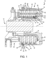
- Aircraft wheel brake assembly 10 such as may be found on an aircraft, in accordance with various embodiments is illustrated.
- Aircraft wheel brake assembly may, for example, comprise a bogie axle 12, a wheel including a hub 16 and a wheel well 18, a web 20, a torque take-out assembly 22, one or more torque bars 24, a wheel rotational axis 26, a wheel well recess 28, an actuator 30, multiple brake rotors 32, multiple brake stators 34, a pressure plate 36, an end plate 38, a heat shield 40, multiple heat shield sections 42, multiple heat shield carriers 44, an air gap 46, multiple torque bar bolts 48, a torque bar pin 50, a wheel web hole 52, multiple heat shield fasteners 53, multiple rotor lugs 54, and multiple stator slots 56.
- Brake disks e.g., interleaved rotors 32 and stators 34
- Rotors 32 are secured to torque bars 24 for rotation with wheel 14, while stators 34 are engaged with torque take-out assembly 22.
- At least one actuator 30 is operable to compress interleaved rotors 32 and stators 34 for stopping the aircraft.
- actuator 30 is shown as a hydraulically actuated piston, but many types of actuators are suitable, such as an electromechanical actuator.
- Pressure plate 36 and end plate 38 are disposed at opposite axial ends of the interleaved rotors 32 and stators 34.
- Rotors 32 and stators 34 can comprise any material suitable for friction disks, including ceramics or carbon materials, such as a carbon/carbon composite.
- Torque take-out assembly 22 is secured to a stationary portion of the landing gear truck such as a bogie beam or other landing gear strut, such that torque take-out assembly 22 and stators 34 are prevented from rotating during braking of the aircraft.
- the friction disks may be formed of carbon-carbon (C/C) composites having carbon fibers disposed in a carbon matrix).
- C/C composites may operate as heat sinks to absorb large amounts of kinetic energy converted to heat during slowing of the aircraft.
- Heat shield 40 may reflect thermal energy away from wheel well 18 and back toward rotors 32 and stators 34.
- brake disks of aircraft wheel brake assembly 10 may reach operating temperatures in the range from about 100°C (212°F) up to about 900°C (1652°F), or higher (e.g., 1093°C (2000°F)).
- the high temperatures experienced by aircraft wheel brake assembly 10 can lead to loss of C/C composite material due to oxidation of carbon.
- various C/C composite components of aircraft wheel brake assembly 10 may experience both catalytic oxidation and inherent thermal oxidation caused by heating the composite during operation.
- rotors 32 and stators 34 may be heated to sufficiently high temperatures that may oxidize the carbon surfaces exposed to air.
- C/C composite components of aircraft wheel brake assembly 10 may retain heat for a substantial time period after slowing the aircraft, oxygen from the ambient atmosphere may react with the carbon matrix and/or carbon fibers to accelerate material loss. Further, damage to brake components may be caused by the oxidation enlargement of cracks around fibers or enlargement of cracks in a reaction-formed porous barrier coating (e.g., a silicon-based barrier coating) applied to the C/C composite.
- a reaction-formed porous barrier coating e.g., a silicon-based barrier coating
- Elements identified in severely oxidized regions of C/C composite brake components include potassium (K) and sodium (Na). These alkali contaminants may come into contact with aircraft brakes as part of cleaning or de-icing materials. Other sources include salt deposits left from seawater or sea spray. These and other contaminants (e.g., Ca, Fe, etc.) can penetrate and leave deposits in pores of C/C composite aircraft brakes, including the substrate and any reaction-formed porous barrier coating. When such contamination occurs, the rate of carbon loss by oxidation can be increased by one to two orders of magnitude.
- an oxidation protection system may be applied to the various components of aircraft wheel brake assembly 10 for protecting the components from oxidation.
- the oxidation protection systems and methods of forming the same may be readily adapted to many parts in this and other brake assemblies, as well as to other C/C composite structures susceptible to oxidation losses from infiltration of atmospheric oxygen and/or catalytic contaminants.
- the oxidation protection system comprises a barrier layer 104, a primary layer 106 and a sealing layer 108.
- the barrier layer 104 can facilitate adhesion between the composite structure 102 and the primary layer 106.
- the barrier layer 104 can be omitted.
- the primary layer 106 is a silicone-based coating that is loaded with metal particles (e.g., alumina particles, silica particles, or the like).
- the primary layer 106 can be sprayed on to form a homogeneous layer.
- a "homogenous layer" as described herein is relative to typical coatings of oxidation protection systems. Stated another way, the primary layer 106 is more homogeneous compared to typical a boron-formed layer of oxidation protection system (e.g., oxidation protection systems that include a boron compound, a glass compound, a glass former compound, a glass modifier, and a carrier fluid).
- the silicone-based coating can then be baked in an inert atmosphere to form a microporous framework.
- the primary layer 106 can be a thin layer with uniform thickness.
- the primary layer 106 can be thinner and lighter relative to typical primary layers of oxidation protection systems, in accordance with various embodiments.
- the sealing layer 108 can then be held by the primary layer 106 and effectively seal the silicone-based coating, as described further herein.
- the primary layer 106 can include pigments 110 (e.g., either leafing pigments (as shown in FIG. 3A ) or non-leafing pigments (as shown in FIG. 3B )).
- leafing pigments can be ball milled with a lubricant (i.e., stearic acid), which produces a pigment with high interfacial tension.
- the interfacial tension can prevent the binders (i.e., silicone resin) or solvent (i.e., water or other solvent) from wetting the pigment surface.
- the solvents within the primary layer 106 i.e., the silicone-based coating
- convection currents push the pigments to the surface of the primary layer 106.
- leafing pigments are coated such that they prevent their surfaces from being wetted (by resin and solvents within the system) they remain atop the surface of the coating as shown in FIG. 3A .
- the overlapping pigments create a pseudo-layer preventing oxidation, in accordance with various embodiments.
- the overlapping pigments can create a pseudo sealing layer between the primary layer 106 and the sealing layer 108.
- non-leafing pigments can be milled in materials that enable the pigment to be readily wetted by the solvents and resins within the primary layer (e.g., the silicone-based coating). This enables the pigments to be distributed homogenously in the coating matrix and after baking create a microporous framework which can subsequently be sealed (e.g., by the sealing layer 108).
- the pigments 110 of FIGs. 3A and 3B can include a median diameter between 0.5 and 70 ⁇ m, or between 5 and 40 ⁇ m, or between 8 and 18 ⁇ m.
- the pigment 110 generally has a laminar structure and functions to form a barrier from corrosive elements thereby protecting the composite structure 102 and serves to improve coating properties.
- Filler materials can include pigments in the form of a paste containing flake metal. These pigments react with O 2 that diffuses into the barrier layer through any defects or fine cracks of the coating system to form oxide and thus serving as oxygen getter. The reaction formed oxides fill the micropores of the barrier layer.
- Embodiments herein can utilize a VOC-free, aluminumbased metallic pigment.
- An example is produced by Shlenk and is commercially called Aquasilber LPW/2140.
- the pigments 110 disclosed herein can be any of the following metals/metalloids and their alloys/oxidated forms: aluminum containing compounds (e.g., aluminum, alumina, etc.), silicon containing compounds (i.e., silica, silicon, etc.)), chromium, iron and alloys thereof (i.e., stainless steel), copper and alloys thereof (i.e., bronze), nickel, silver, gold, etc.
- the pigments 110 include aluminum and/or silicon.
- the pigments 110 comprise between 1% and 20% of the silicone-based coating by weight, or approximately 10% ⁇ 2% by weight of the silicone-based coating.
- the primary layer 106 can be formed such that it includes silicone resin emulsion, a metal pigment 110 (e.g., leafing or non-leafing), a water soluble ionic surfactant, and water.
- a metal pigment 110 e.g., leafing or non-leafing
- a water soluble ionic surfactant e.g., water soluble ionic surfactant
- the emulsion functions as a high heat resistant binder for the pigment element and generally will have a total silicone resin solids content of approximately 38% to 82% by weight.
- the silicone resin emulsion is comprised of 100 parts by weight of (i) at least one silicone resin having one or more organic side groups attached such as phenyl, methyl, trifluoropropyl and/or vinyl moieties; (ii) an anionic surfactant effective for dispersing the resin in a water based emulsion and for binding the resin or particulate phase and the water or continuous phase; and (iii) an amount of water effective for providing a preselected silicone resin solids content by weight of the emulsion.
- the emulsion might also contain trace amounts of volatile organic compounds such as xylene and/or toluene present as a result of the manufacturing process.
- Silicone resins which may be used in the emulsion of the oxidation protection system 100, include optionally crosslinked resins comprising units selected from the group consisting of Rx SiOy where x is 3, 2 or 1 and y is 0.5, 1.0 or 1.5 respectively, and where the R groups are phenyl, methyl, trifluoropropyl and/or vinyl. A typical number average molecular weight and weight average molecular weight of such resins are 420 and 2190, respectively.
- Preferred silicone resins include lightly crosslinked or soft phenylmethyl silicone resins and moderately to highly crosslinked or medium-hard phenylmethyl silicone resins. The most preferred silicone resin is medium-hard phenylmethyl silicone resin where an increase in the hardness and fluid resistance of the cured inventive coating composition has been observed when this moderately to highly crosslinked resin is used.
- Embodiments herein utilize a metal pigment with the proper surfactant.
- a new surfactant is coupled to a new pigment to create a resin system able to provide the necessary properties.
- This coating formulation provides the desired oxidation protection and manufacturability for C/C composite structures.
- the surfactant is an ionic surfactant.
- the surfactant can be a cationic surfactant.
- the surfactant can thus be an ammonium salt of polycarboxylic acid.
- a commercially available version of such a surfactant can be BYK-154 produced by BYK company and which is an ammonium polyacrylate-based dispersing additive for pigments 110.
- a method for limiting an oxidation reaction in a substrate may comprise forming an oxidation protection system on the composite structure 102 from FIG. 2 .
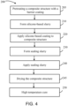
- a method 200 for forming an oxidation protection system 100 on a composite structure 102 is illustrated.
- method 200 may, for example, comprise applying an oxidation inhibiting composition to non-wear surfaces of C/C composite brake components, such as non-wear surfaces 45 and/or lugs 54.
- Non-wear surface 45 as labeled in FIG.
- method 200 may be used on the back face of pressure plate 36 and/or end plate 38, an inner diameter (ID) surface of stators 34 including slots 56, as well as an outer diameter (OD) surface of rotors 32 including lugs 54.
- ID inner diameter
- OD outer diameter
- Method 200 may be performed on densified C/C composites. In this regard, method 200 may be performed after carbonization and densification of the C/C composite.
- method 200 may comprise forming a silicone-based slurry (step 210).
- the silicone-based slurry may be formed from 39.6 to 67.3% by weight of a phenylmethyl silicone resin emulsion having a total weight percent silicone resin solids content of approximately 48 to 72%; (ii) from 8.3 to 19.2% by weight of inhibited metal pigment (e.g., aluminum and/or silicon pigments) (iii) from 0.05 to 3.0% by weight of water soluble ionic surfactant; and (iv) from 10.5 to 52.0% by weight water, and has a total weight percent solids content of approximately 24.4 to 50.0 %.
- the metal pigments e.g., the leafing ( FIG. 3A ) or non-leafing ( FIG. 3B ) pigments 110 can be configured for oxygen (O 2 gettering) during operation of the oxidation protection system 100 from FIG. 2 , in accordance with various embodiments.
- the silicone-based slurry can further include antifoams, pH buffers, anti-rust agents, biocides, fungicides, antifreeze agents, etc.
- antifoams may have an adverse effect on the coating's durability, oxidation protection, coating properties and/or resistance to high temperatures.
- the silicone-based slurry In preparing the silicone-based slurry, water and surfactant are blended together and the surfactant is allowed to dissolve for at least thirty (30) minutes. The leafing pigment is then added to the resulting water solution. Dispersion of the filler material in the water solution is achieved by gentle agitation of the solution with a paddle to break apart the large agglomerates. This is followed by ensuring that the leafing pigment is completely covered by the water solution and allowing the filler material to fully disperse by soaking for approximately 24 to 72 hours. During this period, the dispersion is agitated at least twice per twenty four hour period. A letdown is then prepared by blending a silicone resin emulsion and water for approximately 15 to 20 minutes. The letdown is allowed to fully dissolve for approximately 24 to 72 hours. The dispersion is then added to the letdown and thoroughly blended. The resulting admixture is then allowed to fully disperse for at least 24 hours. As can be well understood by those skilled in the art, excessive stirring during preparation of the coating composition is
- method 200 further comprises applying the silicone-based slurry to a composite structure 102 (step 220).
- Applying the silicone-based slurry may comprise, for example, spraying or brushing the silicone-based slurry to an outer surface of the composite structure. Any suitable manner of applying the silicone-based slurry to the composite structure is within the scope of the present disclosure.
- the composite structure may refer to a C/C composite structure.
- the silicone-based slurry may be applied directly on (i.e., in physical contact with) the surface of the composite structure.
- the silicone-based slurry applied in step 220 can be cured prior to applying the sealing slurry in step 230 (i.e., baked in an inert atmosphere to form microporous framework of a silicone-based coating).
- the silicone-based slurry can be cured with the sealing slurry from step 230 (e.g., in step 250), in accordance with various embodiments.
- method 200 may comprise forming a sealing slurry (step 230) by combining a silicon compound, a glass mixture, a silica glass former compound, and a glass modifier with a carrier fluid (such as, for example, water).
- a carrier fluid such as, for example, water.
- the silicon compound may comprise at least one silicon-comprising refractory material (e.g., ceramic material).
- the silicon compound may comprise silicon carbide, a silicide compound, silicon, silicon dioxide, silicon carbonitride, or combinations thereof.
- the silicon slurry may comprise from about 5.0% to about 30.0% by weight silicon compound, from about 10.0% to about 20.0% by weight silicon compound, from about 9.0% to about 11.0% by weight silicon compound, or from about 18.0% to about 20.0% by weight silicon compound.
- the term “about” means ⁇ 1.0 weight percent.
- the silicon slurry may comprise approximately 18.9% by weight silicon compound.
- the term “approximately” means ⁇ 0.50 weight percent.
- the silicon slurry may comprise approximately 10.1% by weight silicon compound.
- the term “approximately” means ⁇ 0.50 weight percent.
- the silicon slurry may comprise approximately 18.8% by weight silicon compound.
- the term “approximately” means ⁇ 0.50 weight percent.
- the silicon compound is a powder (e.g., silicon powder or silicon carbide powder).
- the silicon compound powder may comprise particles having an average particle size of between about 100 nm and 50 ⁇ m, between 500 nm and 20 ⁇ m, between 500 nm and 1.5 ⁇ m, or between 16 ⁇ m and 18 ⁇ m.
- the term “about” means ⁇ 1.0 ⁇ m.
- the silicon compound may comprise particles having an average particle size of approximately 0.7 ⁇ m.
- the term “about” means ⁇ 0.25 ⁇ m.
- the silicon compound may comprise particles having an average particle size of approximately 1.0 ⁇ m.
- the term "about” means ⁇ 0.25 ⁇ m.
- the glass mixture of the sealing slurry comprises at least two glass compounds.
- the glass mixture can comprise a first glass compound and a second glass compound.
- the first glass compound and the second glass compound can have different melting temperatures.
- the glass mixture of the boron slurry may comprise at least two of the following glass compounds: a phosphate-based glass, an alkaline glass, a borosilicate glass, a silicate glass (e.g., a SiO 2 based glass), an SiON glass, and/or a high-temperature melting point glass as described further herein.
- the glass mixture of the boron slurry comprises a phosphate-based glass and a borosilicate glass.
- the glass mixture comprises a phosphate-based glass, a first borosilicate glass, and a second borosilicate glass.
- a first glass compound in the glass mixture can comprise a viscosity temperature profile that is different from a second glass compound.
- a viscosity at a first temperature of a first glass compound of the glass mixture is less than a viscosity at the first temperature of a second glass compound of the glass mixture by orders of magnitude.
- a first glass compound can have a viscosity of approximately 1.0 x 10 5 Pa ⁇ S at 1,250 °F (677 °C) and a second glass compound can have a viscosity of approximately 1 ⁇ 10 9 Pa ⁇ S at 1,250 °F (677 °C).
- the first glass compound can have a viscosity that is order of magnitudes less than the second glass compound at a second temperature.
- the first glass compound of the glass mixture can have a viscosity at 1,650 °F (899 °C) of approximately 3.2 ⁇ 10 2 Pa ⁇ S and the second glass compound can have a viscosity at 1,650 °F (899 °C) of approximately 3.0 ⁇ 10 5 Pa ⁇ S.
- the first glass compound of the glass mixture includes a viscosity at 1,250 °F (677 °C) between 5.0 ⁇ 10 4 Pa ⁇ S and 5.0 ⁇ 10 5 Pa ⁇ S, or between 7.5 ⁇ 10 4 Pa ⁇ S and 2.5 ⁇ 10 5 Pa ⁇ S, or approximately 1.0 ⁇ 10 5 Pa ⁇ S.
- the first glass compound can have a viscosity at 1,650 °F (899 °C) between 8.2 ⁇ 10 1 Pa ⁇ S and 8.2 ⁇ 10 2 Pa ⁇ S, or between 0.7 ⁇ 10 2 Pa ⁇ S and 5.7 ⁇ 10 5 Pa ⁇ S, or approximately 3.2 ⁇ 10 2 Pa ⁇ S.
- the second glass compound of the glass mixture includes a viscosity at 1,250 °F (677 °C) between 5.0 ⁇ 10 8 Pa ⁇ S and 5.0 ⁇ 10 9 Pa ⁇ S, or between 7.5 ⁇ 10 8 Pa ⁇ S and 2.5 ⁇ 10 9 Pa ⁇ S, or approximately 1.0 ⁇ 10 9 Pa ⁇ S.
- the second glass compound can have a viscosity at 1,650 °F (899 °C) between 8.0 ⁇ 10 4 Pa ⁇ S and 8.0 ⁇ 10 5 Pa ⁇ S, or between 0.5 ⁇ 10 5 Pa ⁇ S and 5.5 ⁇ 10 5 Pa ⁇ S, or approximately 3.0 ⁇ 10 5 Pa ⁇ S.
- a softening viscosity of a coating made from the glass mixture can be significantly broadened.
- a softening viscosity of a coating made from the process described herein can be within the range of 1 ⁇ 10 4 and 1 ⁇ 10 9 Pa ⁇ S for a wide temperature range (e.g., between 1,000 °F (538 °C) and 1,800 °F (982 °C)) as described further herein.
- the glass mixture can comprise a third glass compound with a viscosity temperature profile that is between the first glass compound and the second glass compound.
- the third glass compound of the glass mixture includes a viscosity at 1,250 °F (677 °C) between 8.1 ⁇ 10 6 Pa ⁇ S and 8.1 ⁇ 10 7 Pa ⁇ S, or between 0.6 ⁇ 10 7 Pa ⁇ S and 5.6 ⁇ 10 7 Pa ⁇ S, or approximately 3.1 ⁇ 10 7 Pa ⁇ S.
- the third glass compound can have a viscosity at 1,650 °F (899 °C) between 5.0 ⁇ 10 4 Pa ⁇ S and 5.0 ⁇ 10 5 Pa ⁇ S, or between 7.5 ⁇ 10 4 Pa ⁇ S and 2.5 ⁇ 10 5 Pa ⁇ S, or approximately 1.0 ⁇ 10 5 Pa ⁇ S.
- the third glass compound can comprise a viscosity of approximately 3.1 ⁇ 10 7 Pa ⁇ S at 1,250 °F (677 °C) and a viscosity of approximately 1.0 ⁇ 10 5 at 1,650 °F (899 °C).
- the first glass compound can have a viscosity temperature profile in accordance with FIG. 5A
- the second glass compound can have a viscosity temperature profile in accordance with FIG. 5C
- the third glass compound can have a viscosity temperature profile in accordance with FIG. 5B .
- the glass mixture could include only two of the three glass compounds shown in FIGs. 5A-C
- the glass mixture could include additional glass compounds, or the like.
- the first glass compound of the glass mixture comprises a phosphate-based glass.
- the phosphate-based glass can comprise in mol percentage of the first glass compound, about 1.0% SiO 2 , about 6.5% B 2 O 3 , about 0.8% Al 2 O 3 , about 12% MgO, about 3.5% BaO, about 20% Li 2 O, about 0.1% F, and about 56% P 2 O 5 .
- the term "about” means ⁇ 1.0 mol percent.
- the first glass compound may form approximately 20% ⁇ 10 weight percent of the glass mixture.
- the second glass compound of the glass mixture comprises a first borosilicate glass.
- the second glass compound can comprise, in mol percentage of the second glass compound, about 75% SiO 2 , about 21% B 2 O 3 , about 2% Al 2 O 3 , and about 2% Na 2 O.
- the term "about” means ⁇ 1.0 mol percent.
- the second glass compound may form approximately 30% ⁇ 10 weight percent of the glass mixture.
- the third glass compound of the glass mixture comprises a second borosilicate glass.
- the third glass compound can comprise, in mol percentage of the third glass compound, about 61% SiO 2 , about 27% B 2 O 3 , about 1% BaO, about 1% Li 2 O, about 1% Na 2 O, and about 0.5% K 2 O.
- the term "about” means ⁇ 1.0 mol percent.
- the second glass compound may form approximately 50% ⁇ 20 weight percent of the glass mixture.
- a working point of the first glass compound is between 1450 °F (788 °C) and 1650 °F (899 °C), or approximately 1575 °F (857 °C).
- a working point of the second glass compound is between 2,200 °F (1,204 °C) and 2,400 °F (1,316 °C), or approximately 2,285 °F (1,252 °C).
- a working point of the third glass compound is between 1,950 °F (1,066 °C) and 2,150 °F (1,177 °C).
- “Working point” as referred to herein, is a temperature when a viscosity of the glass compound is 1.0 ⁇ 10 3 Pa ⁇ S.
- the silica glass former may include colloidal silica, metal silicates, alkyl silicates, and/or elemental silica.
- the silica glass former is a colloidal silica suspension having 40.0% by weight silica.
- the silica glass former may be silicon powder.
- the silica glass former may form between about 10.0% and about 40.0%, between about 20.0% and about 30.0%, between about 22.0% and about 24.0%, or between about 24.0% and 26.0% of the weight percentage of the silicon slurry.
- the term "about" means ⁇ 1.0 weight percent.
- the silica glass former may form approximately 22.7% of the weight percentage of the silicon slurry. As used the previous context only, the term “approximately” means ⁇ 0.5 weight percent. In various embodiments, the silica glass former may form approximately 25.2% of the weight percentage of the silicon slurry. As used the previous context only, the term “approximately” means ⁇ 0.5 weight percent. In various embodiments, the silica glass former may form approximately 22.5% of the weight percentage of the silicon slurry. As used the previous context only, the term “approximately” means ⁇ 0.5 weight percent.
- the silicon slurry may also comprise monoaluminium phosphate.
- the monoaluminium phosphate may be in the form of a solution (e.g., monoaluminium phosphate and a carrier fluid) of any suitable make-up.
- the monoaluminium phosphate solution may comprise about 50% by weight monoaluminium phosphate and about 50% by weight carrier fluid (e.g., water). In the previous context only, the term "about” means ⁇ 10 weight percent.
- the monoaluminium phosphate solution may form between about 1% and about 10%, between about 2% and about 5%, or between about 3% and about 4% of the weight percentage of the silicon slurry.
- the term “about” means ⁇ 1.0 weight percent.
- the monoaluminium phosphate solution may form approximately 3.03% of the weight percentage of the silicon slurry.
- the term “approximately” means ⁇ 0.5 weight percent.
- the monoaluminium phosphate solution may form approximately 3.36% of the weight percentage of the silicon slurry.
- the term “approximately” means ⁇ 0.5 weight percent.
- the silicon slurry may also comprise a glass modifier.
- the glass modifier may include an alkaline earth metal compound such as, for example, calcium boride (CaB 6 ), calcium oxide (CaO), calcium carbonate (Ca(CO 3 ) 2 ), magnesium boride (MgB 2 ), magnesium oxide (MgO), magnesium carbonate (Mg(CO 3 ) 2 ), a zirconium compound such as, for example, zirconium boride (ZrB 2 ), zirconium oxide (ZrO), zirconium carbonate (Zr(CO 3 ) 2 ), and/or an aluminum compound such as aluminum oxide (Al 2 O 3 ).
- an alkaline earth metal compound such as, for example, calcium boride (CaB 6 ), calcium oxide (CaO), calcium carbonate (Ca(CO 3 ) 2 ), magnesium boride (MgB 2 ), magnesium oxide (MgO), magnesium carbonate (Mg(CO 3 ) 2 ), a zirconium
- the glass modifier reacts with the borosilicate glass and refractory oxides that may form during oxidation, thereby resulting in a more stable and/or denser glass ceramic coating at associated temperature range.
- the glass modifier may form between about 1.0% and about 15.0%, between about 3.0% and about 10.0%, or between about 5.0% and about 7.0% of the weight percentage of the silicon slurry.
- the term “about” means ⁇ 1.0 weight percent.
- the glass modifier may form approximately 6.1% of the weight percentage of the silicon slurry.
- the term “approximately” means ⁇ 0.5 weight percent.
- the glass modifier may form approximately 6.7% of the weight percentage of the silicon slurry.
- the term “approximately” means ⁇ 0.5 weight percent.
- the silicon slurry may comprise, in weight percentage, 18.94% silicon carbide powder, 22.73% borosilicate glass, 3.03% monoaluminium phosphate solution, 22.73% colloidal silica suspension, 6.06% zirconium boride, and 26.52% water.
- the borosilicate glass may comprise in weight percentage 13% B 2 O 3 , 61% SiO 2 , 2% Al 2 O 3 , and 4% Na 2 O, and may have a CTE of 3.3 ⁇ 10 -6 cm/C, a working point of 2286° F (1252° C), and an annealing point of 1040° F (560° C).
- the colloidal silica suspension may be 40% by weight silica.
- the monoaluminium phosphate solution may be 50% by weight monoaluminium phosphate and 50% by weight carrier fluid.
- the silicon slurry may comprise, in weight percentage, 10.08% silicon carbide powder, 25.21% borosilicate glass, 3.36% monoaluminium phosphate solution, 25.21% colloidal silica suspension, 6.72% zirconium boride, and 29.41% water.
- the borosilicate glass may comprise in weight percentage 13% B 2 O 3 , 61% SiO 2 , 2% Al 2 O 3 , and 4% Na 2 O, and may have a CTE of 3.3 ⁇ 10 -6 cm/C, a working point of 2286° F (1252° C), and an annealing point of 1040° F (560° C).
- the colloidal silica suspension may be 40% by weight silica.
- the monoaluminium phosphate solution may be 50% by weight monoaluminium phosphate and 50% by weight carrier fluid.
- the silicon slurry may comprise, in weight percentage, 18.80% silicon carbide powder, 22.56% borosilicate glass, 3.01% monoaluminium phosphate solution, 22.56% colloidal silica suspension, 6.77% zirconium boride, and 26.32% water.
- the borosilicate glass may comprise in weight percentage 13% B 2 O 3 , 61% SiO 2 , 2% Al 2 O 3 , and 4% Na 2 O, and may have a CTE of 3.3 ⁇ 10 -6 cm/C, a working point of 2286° F (1252° C), and an annealing point of 1040° F (560° C).
- the colloidal silica suspension may be 40% by weight silica.
- the monoaluminium phosphate solution may be 50% by weight monoaluminium phosphate and 50% by weight carrier fluid.
- the sealing layer is configured to seal the microporous silica framework formed from the silicone-based coating in steps 220, 225.
- the sealing layer 108 can sit on a thin barrier layer formed on the primary layer 106 (e.g., leafing layer 107 as shown in FIG. 3A ).
- method 200 further comprises applying the sealing slurry to the composite structure (step 240).
- Applying the silicon slurry may comprise, for example, spraying or brushing the silicon slurry over the surface on which the boron slurry was applied (e.g., the silicon slurry is applied over the boron slurry). Any suitable manner of applying the silicon slurry to the composite structure is within the scope of the present disclosure.
- the composite structure may refer to a C/C composite structure.
- method 200 may further comprise performing a high temperature cure (step 250) to form a primary layer 106 (e.g., comprising a microporous silica framework) on the composite structure 102 and a sealing-glass layer (e.g., sealing layer 108) on the primary layer 106.
- a primary layer 106 e.g., comprising a microporous silica framework
- a sealing-glass layer e.g., sealing layer 108
- the microporous Silica framework of the primary layer 106 can be penetrated by the sealing-glass layer (e.g., sealing layer 108), in accordance with various embodiments.
- Step 250 may include heating the composite structure at a relatively high temperature, for example, a temperature of between 1200° F (649° C) to about 2000° F (1093° C), between about 1500° F (816° C) to about 1700° F (927° C), or about 1650° F (899° C), wherein the term "about” in previous context only means ⁇ 25° F ( ⁇ 14° C)).
- Step 250 may include heating the composite structure for about 5 minutes to about 8 hours, about 30 minutes to about 5 hours, or about 2 hours, wherein the term "about” in this context only means ⁇ 10 % of the associated value.
- method 200 may further comprise applying at least one of a pretreating composition or a barrier coating (step 205) prior to applying the first slurry.
- Step 205 may, for example, comprise applying a first pretreating composition to an outer surface of a composite structure, such as a component of aircraft wheel brake assembly 10.
- the first pretreating composition comprises an aluminum oxide in water.
- the aluminum oxide may comprise an additive, such as a nanoparticle dispersion of aluminum oxide (for example, NanoBYK-3600 ® sold by BYK Additives & Instruments).
- the first pretreating composition may further comprise a surfactant or a wetting agent.
- the composite structure may be porous, allowing the pretreating composition to penetrate at least a portion of the pores of the composite structure.
- the component after applying the first pretreating composition, the component may be heated to remove water and fix the aluminum oxide in place.
- the component may be heated between about 100° C. (212° F.) and 200° C. (392° F.), and further, between 100° C. (212° F.) and 150° C. (302° F.).
- the pretreatment composition may comprise monoaluminium phosphate.
- the monoaluminium phosphate may be in the form of a solution (e.g., monoaluminium phosphate and a carrier fluid) of any suitable make-up.
- the monoaluminium phosphate solution may comprise about 50% by weight monoaluminium phosphate and about 50% by weight carrier fluid (e.g., water). In the previous context only, the term "about" means ⁇ 10 weight percent.
- the composite structure is heated to remove carrier fluid and fix the monoaluminium phosphate over the composite structure.
- method 300 may include applying the boron slurry (step 220) after heating the composite structure to remove the carrier fluid (e.g., water) of the pretreatment composition.
- references to "one embodiment,” “an embodiment,” “an example embodiment,” etc. indicate that the embodiment described may include a particular feature, structure, or characteristic, but every embodiment may not necessarily include the particular feature, structure, or characteristic. Moreover, such phrases are not necessarily referring to the same embodiment. Further, when a particular feature, structure, or characteristic is described in connection with an embodiment, it is submitted that it is within the knowledge of one skilled in the art to affect such feature, structure, or characteristic in connection with other embodiments whether or not explicitly described. After reading the description, it will be apparent to one skilled in the relevant art(s) how to implement the disclosure in alternative embodiments that fall within the scope of the claims.
Landscapes
- Chemical & Material Sciences (AREA)
- Engineering & Computer Science (AREA)
- Materials Engineering (AREA)
- Organic Chemistry (AREA)
- Life Sciences & Earth Sciences (AREA)
- Wood Science & Technology (AREA)
- Ceramic Engineering (AREA)
- Structural Engineering (AREA)
- Inorganic Chemistry (AREA)
- General Engineering & Computer Science (AREA)
- Chemical Kinetics & Catalysis (AREA)
- Nanotechnology (AREA)
- Composite Materials (AREA)
- Mechanical Engineering (AREA)
- Paints Or Removers (AREA)
Abstract
A method for forming an oxidation protection system on a carbon-carbon composite structure (102) comprises applying a silicone-based slurry to the carbon-carbon composite structure, the silicone-based slurry including metal pigments disposed therein; applying a sealing slurry to the silicone-based slurry; and heating the carbon-carbon composite structure.
Description
- The present disclosure relates generally to composites and, more specifically, to oxidation protection systems for carbon-carbon composite structures.
- Oxidation protection systems for carbon-carbon composites are typically designed to minimize loss of carbon material due to oxidation at high temperature operating conditions, which include temperatures of427°C (800°F) or greater. Carbon-carbon composites have high specific strength, ranging from low to very high temperatures. However, carbon-carbon composites are intrinsically prone to oxidation in ambient environment to form carbon monoxide and carbon dioxide gases, losing mass and strength. Oxidation protection system (OPS) facilitate increased life cycles for carbon-carbon composite components, especially when used at high temperature applications.
- OPS coatings to protect C/C composite from oxidation damage through forming a barrier to block oxygen diffusion into the C/C substrate, in addition, oxygen gettering phase is also incorporated in the coating structure to remove O2 molecules that diffused into the coating through fine cracks and defects.
- A method for forming an oxidation protection system on a carbon-carbon composite structure is disclosed herein. In various embodiments, the method comprises applying a silicone-based slurry to the carbon-carbon composite structure, the silicone-based slurry including metal pigments disposed therein; applying a sealing slurry to the silicone-based slurry; and heating the carbon-carbon composite structure.
- In various embodiments, the sealing slurry comprises a silicon compound, a glass mixture, a glass former, a glass modifier, and a carrier fluid. In various embodiments, the glass mixture including a first glass compound and a second glass compound, the first glass compound having a first viscosity-temperature profile that is at least two orders of magnitude below a second viscosity-temperature profile of the second glass compound.
- In various embodiments, the metal pigments include at least one of aluminum, silicon, chromium, iron, copper, nickel, silver, and gold. In various embodiments, the metal pigments include at least one of aluminum and silicon.
- In various embodiments, the metal pigments are between 1% and 20% by weight of the silicone-based slurry.
- In various embodiments, the metal pigments include a median diameter range between 0.5 µm and 70 µm.
- In various embodiments, the metal pigments are leafing pigments, and wherein in response to solvents in the silicone-based slurry evaporating, convection currents push the metal pigments to a surface of a silicone-based coating formed from the silicone-based slurry from the heating of the carbon-carbon composite structure.
- In various embodiments, the metal pigments are non-leafing pigments, and wherein in response to the heating of the carbon-carbon composite structure, the non-leafing pigments are distributed throughout a silicone-based coating formed from the silicone-based slurry.
- A carbon-carbon composite component is disclosed herein. In various embodiments, the carbon-carbon composite component comprises a composite structure; an oxidation protection system disposed on the composite structure, the oxidation protection system including: a primary layer coupled to the composite structure, the primary layer including a silicone-based coating with metal pigments, and a sealing layer coupled to the primary layer, the sealing layer configured to penetrate a microporous framework of the primary layer.
- In various embodiments, the metal pigments comprise leafing metal pigments. In various embodiments, the leafing metal pigments form a leafing layer between the primary layer and the sealing layer.
- In various embodiments, the metal pigments comprise non-leafing metal pigments distributed throughout the silicone-based coating.
- In various embodiments, the metal pigments include a median diameter range between 0.5 µm and 70 µm.
- In various embodiments, the metal pigments are between 1% and 20% by weight of the silicone-based coating.
- In various embodiments, the metal pigments comprise at least one of aluminum, silicon, chromium, iron, copper, nickel, silver, and gold.
- An oxidation protection system for a carbon-carbon composite structure is disclosed herein. In various embodiments, the oxidation protection system comprising a silicone-based coating configured to couple to the carbon-carbon composite structure, the silicone-based coating including metal pigments, and a sealing layer configured to couple to the silicone-based coating, the sealing layer configured to penetrate a microporous framework formed from the silicone-based coating, the sealing layer formed from a glass mixture including a first glass compound and a second glass compound, the first glass compound having a first viscosity-temperature profile that is at least two orders of magnitude below a second viscosity-temperature profile of the second glass compound.
- In various embodiments, the metal pigments are leafing metal pigments, and wherein, the leafing metal pigments form a leafing layer between the silicone-based coating and the sealing layer.
- In various embodiments, the metal pigments are non-leafing metal pigments, and wherein the metal pigments are distributed throughout the silicone-based coating.
- In various embodiments, the metal pigments comprise at least one of aluminum, silicon, chromium, iron, copper, nickel, silver, and gold.
- The subject matter of the present disclosure is particularly pointed out and distinctly claimed in the concluding portion of the specification. A more complete understanding of the present disclosure, however, may best be obtained by referring to the detailed description and claims when considered in connection with the drawing figures, wherein like numerals denote like elements.
-
FIG. 1 illustrates a cross sectional view of an aircraft wheel brake assembly, in accordance with various embodiments; -
FIG. 2 illustrates a carbon-carbon composite structure with an oxidation protection system, in accordance with various embodiments; -
FIG. 3A illustrates a carbon-carbon composite structure with an oxidation protection system, in accordance with various embodiments; -
FIG. 3B illustrates a carbon-carbon composite structure with an oxidation protection system, in accordance with various embodiments; -
FIG. 4 illustrates a method for forming an oxidation protection system on a composite structure, in accordance with various embodiments; -
FIG. 5A illustrates a viscosity-temperature profile for a glass compound in a glass mixture of a sealing layer of an oxidation protection system, in accordance with various embodiments; -
FIG. 5B illustrates a viscosity-temperature profile for a glass compound in a glass mixture of a sealing layer of an oxidation protection system, in accordance with various embodiments; and -
FIG. 5C illustrates a viscosity-temperature profile for a glass compound in a glass mixture of a sealing layer of an oxidation protection system, in accordance with various embodiments. - The detailed description of embodiments herein makes reference to the accompanying drawings, which show embodiments by way of illustration. While these embodiments are described in sufficient detail to enable those skilled in the art to practice the disclosure, it should be understood that other embodiments may be realized and that logical and mechanical changes may be made without departing from the spirit and scope of the disclosure. Thus, the detailed description herein is presented for purposes of illustration only and not for limitation. For example, any reference to singular includes plural embodiments, and any reference to more than one component or step may include a singular embodiment or step. Also, any reference to attached, fixed, connected or the like may include permanent, removable, temporary, partial, full and/or any other possible attachment option.
- Disclosed herein is an advanced OPS that utilizes a silicone-based coating as a building block for oxidation protection of a carbon-carbon composite component.
- The advanced OPS is composed of multiple layers, with a thin barrier layer that can bond well with C/C composite substrate. Silicone-based coating loaded with metal particles (e.g., aluminum and/or silicon) can be sprayed on to form a homogeneous layer. The coating can then bake in an inert atmosphere to form a microporous framework. The thin layer with homogeneous thickness then can hold a thin glass layer that can effectively seal the coating structure.
- In various embodiments, a sealing layer can be formed on the silicone-based coating. The sealing layer can be one or a combination of phosphate glass, alkaline glass, borosilicate glass, SiO2, SiOC, SiON glass, and high temperature glass, depending on the temperature range of the C/C composite components operate. The glass layer can provide a seal for the microporous silica framework, which sits on a thin barrier layer on the glass.
- With initial reference to
FIG. 1 , aircraftwheel brake assembly 10 such as may be found on an aircraft, in accordance with various embodiments is illustrated. Aircraft wheel brake assembly may, for example, comprise abogie axle 12, a wheel including ahub 16 and awheel well 18, aweb 20, a torque take-out assembly 22, one ormore torque bars 24, a wheelrotational axis 26, a wheel well recess 28, anactuator 30,multiple brake rotors 32,multiple brake stators 34, apressure plate 36, anend plate 38, aheat shield 40, multipleheat shield sections 42, multipleheat shield carriers 44, anair gap 46, multipletorque bar bolts 48, atorque bar pin 50, awheel web hole 52, multipleheat shield fasteners 53,multiple rotor lugs 54, andmultiple stator slots 56. - Brake disks (e.g., interleaved
rotors 32 and stators 34) are disposed in wheel well recess 28 of wheel well 18.Rotors 32 are secured totorque bars 24 for rotation withwheel 14, whilestators 34 are engaged with torque take-outassembly 22. At least oneactuator 30 is operable to compress interleavedrotors 32 andstators 34 for stopping the aircraft. In this example,actuator 30 is shown as a hydraulically actuated piston, but many types of actuators are suitable, such as an electromechanical actuator.Pressure plate 36 andend plate 38 are disposed at opposite axial ends of the interleavedrotors 32 andstators 34.Rotors 32 andstators 34 can comprise any material suitable for friction disks, including ceramics or carbon materials, such as a carbon/carbon composite. - Through compression of interleaved
rotors 32 andstators 34 betweenpressure plates 36 andend plate 38, the resulting frictional contact slows rotation ofwheel 14. Torque take-outassembly 22 is secured to a stationary portion of the landing gear truck such as a bogie beam or other landing gear strut, such that torque take-outassembly 22 andstators 34 are prevented from rotating during braking of the aircraft. - The friction disks (e.g.,
rotors 32,stators 34,pressure plate 36, end plate 38) may be formed of carbon-carbon (C/C) composites having carbon fibers disposed in a carbon matrix). The C/C composites may operate as heat sinks to absorb large amounts of kinetic energy converted to heat during slowing of the aircraft.Heat shield 40 may reflect thermal energy away from wheel well 18 and back towardrotors 32 andstators 34. - In various embodiments, brake disks of aircraft
wheel brake assembly 10 may reach operating temperatures in the range from about 100°C (212°F) up to about 900°C (1652°F), or higher (e.g., 1093°C (2000°F)). The high temperatures experienced by aircraftwheel brake assembly 10 can lead to loss of C/C composite material due to oxidation of carbon. For example, various C/C composite components of aircraftwheel brake assembly 10 may experience both catalytic oxidation and inherent thermal oxidation caused by heating the composite during operation. In various embodiments,rotors 32 andstators 34 may be heated to sufficiently high temperatures that may oxidize the carbon surfaces exposed to air. At elevated temperatures, infiltration of air and contaminants may cause internal oxidation and weakening, especially in and around brake rotor lugs 54 orstator slots 56 securing the friction disks to therespective torque bar 24 and torque take-outassembly 22. Because C/C composite components of aircraftwheel brake assembly 10 may retain heat for a substantial time period after slowing the aircraft, oxygen from the ambient atmosphere may react with the carbon matrix and/or carbon fibers to accelerate material loss. Further, damage to brake components may be caused by the oxidation enlargement of cracks around fibers or enlargement of cracks in a reaction-formed porous barrier coating (e.g., a silicon-based barrier coating) applied to the C/C composite. - Elements identified in severely oxidized regions of C/C composite brake components include potassium (K) and sodium (Na). These alkali contaminants may come into contact with aircraft brakes as part of cleaning or de-icing materials. Other sources include salt deposits left from seawater or sea spray. These and other contaminants (e.g., Ca, Fe, etc.) can penetrate and leave deposits in pores of C/C composite aircraft brakes, including the substrate and any reaction-formed porous barrier coating. When such contamination occurs, the rate of carbon loss by oxidation can be increased by one to two orders of magnitude.
- In various embodiments, an oxidation protection system, as disclosed herein, may be applied to the various components of aircraft
wheel brake assembly 10 for protecting the components from oxidation. However, it will be recognized that the oxidation protection systems and methods of forming the same, as disclosed herein, may be readily adapted to many parts in this and other brake assemblies, as well as to other C/C composite structures susceptible to oxidation losses from infiltration of atmospheric oxygen and/or catalytic contaminants. - Referring now to
FIG. 2 , anoxidation protection system 100 for protecting a C/C composite structure (e.g., composite structure 102) is illustrated, in accordance with various embodiments. In various embodiments, the oxidation protection system comprises abarrier layer 104, aprimary layer 106 and asealing layer 108. In various embodiments, thebarrier layer 104 can facilitate adhesion between thecomposite structure 102 and theprimary layer 106. In various embodiments, thebarrier layer 104 can be omitted. In various embodiments, as described further herein, theprimary layer 106 is a silicone-based coating that is loaded with metal particles (e.g., alumina particles, silica particles, or the like). In various embodiments, theprimary layer 106 can be sprayed on to form a homogeneous layer. A "homogenous layer" as described herein is relative to typical coatings of oxidation protection systems. Stated another way, theprimary layer 106 is more homogeneous compared to typical a boron-formed layer of oxidation protection system (e.g., oxidation protection systems that include a boron compound, a glass compound, a glass former compound, a glass modifier, and a carrier fluid). In various embodiments, the silicone-based coating can then be baked in an inert atmosphere to form a microporous framework. In various embodiments, theprimary layer 106 can be a thin layer with uniform thickness. In various embodiments, by having a more homogeneous layer relative to typical oxidation protection systems, theprimary layer 106 can be thinner and lighter relative to typical primary layers of oxidation protection systems, in accordance with various embodiments. Thesealing layer 108 can then be held by theprimary layer 106 and effectively seal the silicone-based coating, as described further herein. - In various embodiments, the
primary layer 106 can include pigments 110 (e.g., either leafing pigments (as shown inFIG. 3A ) or non-leafing pigments (as shown inFIG. 3B )). In various embodiments, leafing pigments can be ball milled with a lubricant (i.e., stearic acid), which produces a pigment with high interfacial tension. The interfacial tension can prevent the binders (i.e., silicone resin) or solvent (i.e., water or other solvent) from wetting the pigment surface. As the solvents within the primary layer 106 (i.e., the silicone-based coating) evaporates, convection currents push the pigments to the surface of theprimary layer 106. Since leafing pigments are coated such that they prevent their surfaces from being wetted (by resin and solvents within the system) they remain atop the surface of the coating as shown inFIG. 3A . This creates a dense scale-like layer at the surface of the coating. Therefore, with leafing pigments, another barrier can be created between theprimary layer 106 and the sealing layer 108 (e.g., leafinglayer 107 as shown inFIG. 3A ). As the overlapping pigments create a pseudo-layer preventing oxidation, in accordance with various embodiments. In this regard, the overlapping pigments can create a pseudo sealing layer between theprimary layer 106 and thesealing layer 108. - Conversely, in accordance with various embodiments, non-leafing pigments can be milled in materials that enable the pigment to be readily wetted by the solvents and resins within the primary layer (e.g., the silicone-based coating). This enables the pigments to be distributed homogenously in the coating matrix and after baking create a microporous framework which can subsequently be sealed (e.g., by the sealing layer 108).
- In various embodiments, the
pigments 110 ofFIGs. 3A and 3B can include a median diameter between 0.5 and 70 µm, or between 5 and 40 µm, or between 8 and 18 µm. Thepigment 110 generally has a laminar structure and functions to form a barrier from corrosive elements thereby protecting thecomposite structure 102 and serves to improve coating properties. Filler materials, as disclosed herein, can include pigments in the form of a paste containing flake metal. These pigments react with O2 that diffuses into the barrier layer through any defects or fine cracks of the coating system to form oxide and thus serving as oxygen getter. The reaction formed oxides fill the micropores of the barrier layer. These pigments in addition to functioning as a barrier from corrosive elements and improving coating properties also impart color to the coating composition. Embodiments herein can utilize a VOC-free, aluminumbased metallic pigment. An example is produced by Shlenk and is commercially called Aquasilber LPW/2140. - In various embodiments, the
pigments 110 disclosed herein can be any of the following metals/metalloids and their alloys/oxidated forms: aluminum containing compounds (e.g., aluminum, alumina, etc.), silicon containing compounds (i.e., silica, silicon, etc.)), chromium, iron and alloys thereof (i.e., stainless steel), copper and alloys thereof (i.e., bronze), nickel, silver, gold, etc. In various embodiments, thepigments 110 include aluminum and/or silicon. - In various embodiments, the
pigments 110 comprise between 1% and 20% of the silicone-based coating by weight, or approximately 10% ± 2% by weight of the silicone-based coating. - In various embodiments, the
primary layer 106 can be formed such that it includes silicone resin emulsion, a metal pigment 110 (e.g., leafing or non-leafing), a water soluble ionic surfactant, and water. - The emulsion functions as a high heat resistant binder for the pigment element and generally will have a total silicone resin solids content of approximately 38% to 82% by weight. The silicone resin emulsion is comprised of 100 parts by weight of (i) at least one silicone resin having one or more organic side groups attached such as phenyl, methyl, trifluoropropyl and/or vinyl moieties; (ii) an anionic surfactant effective for dispersing the resin in a water based emulsion and for binding the resin or particulate phase and the water or continuous phase; and (iii) an amount of water effective for providing a preselected silicone resin solids content by weight of the emulsion. The emulsion might also contain trace amounts of volatile organic compounds such as xylene and/or toluene present as a result of the manufacturing process.
- Silicone resins, which may be used in the emulsion of the
oxidation protection system 100, include optionally crosslinked resins comprising units selected from the group consisting of Rx SiOy where x is 3, 2 or 1 and y is 0.5, 1.0 or 1.5 respectively, and where the R groups are phenyl, methyl, trifluoropropyl and/or vinyl. A typical number average molecular weight and weight average molecular weight of such resins are 420 and 2190, respectively. Preferred silicone resins include lightly crosslinked or soft phenylmethyl silicone resins and moderately to highly crosslinked or medium-hard phenylmethyl silicone resins. The most preferred silicone resin is medium-hard phenylmethyl silicone resin where an increase in the hardness and fluid resistance of the cured inventive coating composition has been observed when this moderately to highly crosslinked resin is used. - Embodiments herein utilize a metal pigment with the proper surfactant. In order to ensure the
primary layer 106 provides the most robust corrosion protection a new surfactant is coupled to a new pigment to create a resin system able to provide the necessary properties. This coating formulation provides the desired oxidation protection and manufacturability for C/C composite structures. - In various embodiments, the surfactant is an ionic surfactant. For example, the surfactant can be a cationic surfactant. The surfactant can thus be an ammonium salt of polycarboxylic acid. A commercially available version of such a surfactant can be BYK-154 produced by BYK company and which is an ammonium polyacrylate-based dispersing additive for
pigments 110. - In various embodiments, a method for limiting an oxidation reaction in a substrate (e.g., a C/C composite structure) may comprise forming an oxidation protection system on the
composite structure 102 fromFIG. 2 . With reference toFIG. 4 , amethod 200 for forming anoxidation protection system 100 on acomposite structure 102 is illustrated. In accordance with various embodiments,method 200 may, for example, comprise applying an oxidation inhibiting composition to non-wear surfaces of C/C composite brake components, such asnon-wear surfaces 45 and/or lugs 54.Non-wear surface 45, as labeled inFIG. 1 , simply references an exemplary non-wear surface on a brake disk, but non-wear surfaces similar tonon-wear surface 45 may be present on any brake disks (e.g.,rotors 32,stators 34,pressure plate 36,end plate 38, or the like). In various embodiments,method 200 may be used on the back face ofpressure plate 36 and/orend plate 38, an inner diameter (ID) surface ofstators 34 includingslots 56, as well as an outer diameter (OD) surface ofrotors 32 includinglugs 54.Method 200 may be performed on densified C/C composites. In this regard,method 200 may be performed after carbonization and densification of the C/C composite. - In various embodiments,
method 200 may comprise forming a silicone-based slurry (step 210). The silicone-based slurry may be formed from 39.6 to 67.3% by weight of a phenylmethyl silicone resin emulsion having a total weight percent silicone resin solids content of approximately 48 to 72%; (ii) from 8.3 to 19.2% by weight of inhibited metal pigment (e.g., aluminum and/or silicon pigments) (iii) from 0.05 to 3.0% by weight of water soluble ionic surfactant; and (iv) from 10.5 to 52.0% by weight water, and has a total weight percent solids content of approximately 24.4 to 50.0 %. In various embodiments, the metal pigments (e.g., the leafing (FIG. 3A ) or non-leafing (FIG. 3B ) pigments 110 can be configured for oxygen (O2 gettering) during operation of theoxidation protection system 100 fromFIG. 2 , in accordance with various embodiments. - In various embodiments, the silicone-based slurry can further include antifoams, pH buffers, anti-rust agents, biocides, fungicides, antifreeze agents, etc. However, some such additives may have an adverse effect on the coating's durability, oxidation protection, coating properties and/or resistance to high temperatures.
- In preparing the silicone-based slurry, water and surfactant are blended together and the surfactant is allowed to dissolve for at least thirty (30) minutes. The leafing pigment is then added to the resulting water solution. Dispersion of the filler material in the water solution is achieved by gentle agitation of the solution with a paddle to break apart the large agglomerates. This is followed by ensuring that the leafing pigment is completely covered by the water solution and allowing the filler material to fully disperse by soaking for approximately 24 to 72 hours. During this period, the dispersion is agitated at least twice per twenty four hour period. A letdown is then prepared by blending a silicone resin emulsion and water for approximately 15 to 20 minutes. The letdown is allowed to fully dissolve for approximately 24 to 72 hours. The dispersion is then added to the letdown and thoroughly blended. The resulting admixture is then allowed to fully disperse for at least 24 hours. As can be well understood by those skilled in the art, excessive stirring during preparation of the coating composition is to be avoided.
- In accordance with various embodiments,
method 200 further comprises applying the silicone-based slurry to a composite structure 102 (step 220). Applying the silicone-based slurry may comprise, for example, spraying or brushing the silicone-based slurry to an outer surface of the composite structure. Any suitable manner of applying the silicone-based slurry to the composite structure is within the scope of the present disclosure. As referenced herein, the composite structure may refer to a C/C composite structure. In accordance with various embodiments, the silicone-based slurry may be applied directly on (i.e., in physical contact with) the surface of the composite structure. In various embodiments, the silicone-based slurry applied instep 220 can be cured prior to applying the sealing slurry in step 230 (i.e., baked in an inert atmosphere to form microporous framework of a silicone-based coating). However, the present disclosure is not limited in this regard. For example, the silicone-based slurry can be cured with the sealing slurry from step 230 (e.g., in step 250), in accordance with various embodiments. - In various embodiments,
method 200 may comprise forming a sealing slurry (step 230) by combining a silicon compound, a glass mixture, a silica glass former compound, and a glass modifier with a carrier fluid (such as, for example, water). In various embodiments, the silicon compound may comprise at least one silicon-comprising refractory material (e.g., ceramic material). In various embodiments, the silicon compound may comprise silicon carbide, a silicide compound, silicon, silicon dioxide, silicon carbonitride, or combinations thereof. - In various embodiments, the silicon slurry may comprise from about 5.0% to about 30.0% by weight silicon compound, from about 10.0% to about 20.0% by weight silicon compound, from about 9.0% to about 11.0% by weight silicon compound, or from about 18.0% to about 20.0% by weight silicon compound. As used in previous context only, the term "about" means ±1.0 weight percent. In various embodiments, the silicon slurry may comprise approximately 18.9% by weight silicon compound. As used in previous context only, the term "approximately" means ±0.50 weight percent. In various embodiments, the silicon slurry may comprise approximately 10.1% by weight silicon compound. As used in the previous context only, the term "approximately" means ± 0.50 weight percent. In various embodiments, the silicon slurry may comprise approximately 18.8% by weight silicon compound. As used in the previous context only, the term "approximately" means ± 0.50 weight percent.
- In various embodiments, the silicon compound is a powder (e.g., silicon powder or silicon carbide powder). The silicon compound powder may comprise particles having an average particle size of between about 100 nm and 50 µm, between 500 nm and 20 µm, between 500 nm and 1.5 µm, or between 16 µm and 18 µm. As used in previous context only, the term "about" means ±1.0 µm. In various embodiments, the silicon compound may comprise particles having an average particle size of approximately 0.7 µm. As used in the previous context only, the term "about" means ±0.25 µm. In various embodiments, the silicon compound may comprise particles having an average particle size of approximately 1.0 µm. As used in the previous context only, the term "about" means ±0.25 µm.
- The glass mixture of the sealing slurry comprises at least two glass compounds. For example, the glass mixture can comprise a first glass compound and a second glass compound. The first glass compound and the second glass compound can have different melting temperatures.
- The glass mixture of the boron slurry may comprise at least two of the following glass compounds: a phosphate-based glass, an alkaline glass, a borosilicate glass, a silicate glass (e.g., a SiO2 based glass), an SiON glass, and/or a high-temperature melting point glass as described further herein. In various embodiments, the glass mixture of the boron slurry comprises a phosphate-based glass and a borosilicate glass. In various embodiments, the glass mixture comprises a phosphate-based glass, a first borosilicate glass, and a second borosilicate glass.
- In various embodiments, a first glass compound in the glass mixture can comprise a viscosity temperature profile that is different from a second glass compound. In various embodiments, a viscosity at a first temperature of a first glass compound of the glass mixture is less than a viscosity at the first temperature of a second glass compound of the glass mixture by orders of magnitude. For example, a first glass compound can have a viscosity of approximately 1.0 x 10⁵ Pa·S at 1,250 °F (677 °C) and a second glass compound can have a viscosity of approximately 1 × 10⁹ Pa·S at 1,250 °F (677 °C). Similarly, the first glass compound can have a viscosity that is order of magnitudes less than the second glass compound at a second temperature. For example, the first glass compound of the glass mixture can have a viscosity at 1,650 °F (899 °C) of approximately 3.2 × 10² Pa·S and the second glass compound can have a viscosity at 1,650 °F (899 °C) of approximately 3.0 × 10⁵ Pa·S.
- In various embodiments, the first glass compound of the glass mixture includes a viscosity at 1,250 °F (677 °C) between 5.0 × 10⁴ Pa·S and 5.0 × 10⁵ Pa·S, or between 7.5 × 10⁴ Pa·S and 2.5 × 10⁵ Pa·S, or approximately 1.0 × 10⁵ Pa·S. In various embodiments, the first glass compound can have a viscosity at 1,650 °F (899 °C) between 8.2 × 101 Pa·S and 8.2 × 10² Pa·S, or between 0.7 × 10² Pa·S and 5.7 × 10⁵ Pa·S, or approximately 3.2 × 10² Pa·S.
- In various embodiments, the second glass compound of the glass mixture includes a viscosity at 1,250 °F (677 °C) between 5.0 × 10⁸ Pa·S and 5.0 × 10⁹ Pa·S, or between 7.5 × 10⁸ Pa·S and 2.5 × 10⁹ Pa·S, or approximately 1.0 × 10⁹ Pa·S. In various embodiments, the second glass compound can have a viscosity at 1,650 °F (899 °C) between 8.0 × 10⁴ Pa·S and 8.0 × 10⁵ Pa·S, or between 0.5 × 10⁵ Pa·S and 5.5 × 10⁵ Pa·S, or approximately 3.0 × 10⁵ Pa·S.
- In various embodiments, by having a first glass compound with a viscosity temperature profile with a significantly lower viscosity (i.e., at least two orders of magnitude) at various temperatures relative to a viscosity temperature profile of a second glass compound, a softening viscosity of a coating made from the glass mixture can be significantly broadened. For example, a softening viscosity of a coating made from the process described herein can be within the range of 1 × 10⁴ and 1 × 10⁹ Pa·S for a wide temperature range (e.g., between 1,000 °F (538 °C) and 1,800 °F (982 °C)) as described further herein.
- In various embodiments, the glass mixture can comprise a third glass compound with a viscosity temperature profile that is between the first glass compound and the second glass compound. In various embodiments, the third glass compound of the glass mixture includes a viscosity at 1,250 °F (677 °C) between 8.1 × 10⁶ Pa·S and 8.1 × 10⁷ Pa·S, or between 0.6 × 10⁷ Pa·S and 5.6 × 10⁷ Pa·S, or approximately 3.1 × 10⁷ Pa·S. In various embodiments, the third glass compound can have a viscosity at 1,650 °F (899 °C) between 5.0 × 10⁴ Pa·S and 5.0 × 10⁵ Pa·S, or between 7.5 × 10⁴ Pa·S and 2.5 × 10⁵ Pa·S, or approximately 1.0 × 10⁵ Pa·S. In various embodiments, the third glass compound can comprise a viscosity of approximately 3.1 × 10⁷ Pa·S at 1,250 °F (677 °C) and a viscosity of approximately 1.0 × 10⁵ at 1,650 °F (899 °C).
- With brief reference to
FIG. 5A-C , in various embodiments, the first glass compound can have a viscosity temperature profile in accordance withFIG. 5A , the second glass compound can have a viscosity temperature profile in accordance withFIG. 5C , and the third glass compound can have a viscosity temperature profile in accordance withFIG. 5B . Although described herein as comprising three glass compounds in the glass mixture, the present disclosure is not limited in this regard. For example, the glass mixture could include only two of the three glass compounds shown inFIGs. 5A-C , the glass mixture could include additional glass compounds, or the like. - In various embodiments, the first glass compound of the glass mixture comprises a phosphate-based glass. For example, the phosphate-based glass can comprise in mol percentage of the first glass compound, about 1.0% SiO2, about 6.5% B2O3, about 0.8% Al2O3, about 12% MgO, about 3.5% BaO, about 20% Li2O, about 0.1% F, and about 56% P2O5. As used in previous context only, the term "about" means ±1.0 mol percent. In various embodiments, the first glass compound may form approximately 20% ± 10 weight percent of the glass mixture.
- In various embodiments, the second glass compound of the glass mixture comprises a first borosilicate glass. For example, the second glass compound can comprise, in mol percentage of the second glass compound, about 75% SiO2, about 21% B2O3, about 2% Al2O3, and about 2% Na2O. As used in previous context only, the term "about" means ±1.0 mol percent. In various embodiments, the second glass compound may form approximately 30% ± 10 weight percent of the glass mixture.
- In various embodiments, the third glass compound of the glass mixture comprises a second borosilicate glass. For example, the third glass compound can comprise, in mol percentage of the third glass compound, about 61% SiO2, about 27% B2O3, about 1% BaO, about 1% Li2O, about 1% Na2O, and about 0.5% K2O. As used in previous context only, the term "about" means ±1.0 mol percent. In various embodiments, the second glass compound may form approximately 50% ± 20 weight percent of the glass mixture.
- In various embodiments, a working point of the first glass compound is between 1450 °F (788 °C) and 1650 °F (899 °C), or approximately 1575 °F (857 °C). In various embodiments, a working point of the second glass compound is between 2,200 °F (1,204 °C) and 2,400 °F (1,316 °C), or approximately 2,285 °F (1,252 °C). In various embodiments, a working point of the third glass compound is between 1,950 °F (1,066 °C) and 2,150 °F (1,177 °C). "Working point" as referred to herein, is a temperature when a viscosity of the glass compound is 1.0 × 10³ Pa·S.
- In various embodiments, the silica glass former may include colloidal silica, metal silicates, alkyl silicates, and/or elemental silica. In various embodiments, the silica glass former is a colloidal silica suspension having 40.0% by weight silica. In various embodiments, the silica glass former may be silicon powder. The silica glass former may form between about 10.0% and about 40.0%, between about 20.0% and about 30.0%, between about 22.0% and about 24.0%, or between about 24.0% and 26.0% of the weight percentage of the silicon slurry. As used the previous context only, the term "about" means ±1.0 weight percent. In various embodiments, the silica glass former may form approximately 22.7% of the weight percentage of the silicon slurry. As used the previous context only, the term "approximately" means ±0.5 weight percent. In various embodiments, the silica glass former may form approximately 25.2% of the weight percentage of the silicon slurry. As used the previous context only, the term "approximately" means ±0.5 weight percent. In various embodiments, the silica glass former may form approximately 22.5% of the weight percentage of the silicon slurry. As used the previous context only, the term "approximately" means ±0.5 weight percent.
- In various embodiments, the silicon slurry may also comprise monoaluminium phosphate. The monoaluminium phosphate may be in the form of a solution (e.g., monoaluminium phosphate and a carrier fluid) of any suitable make-up. In various embodiments, the monoaluminium phosphate solution may comprise about 50% by weight monoaluminium phosphate and about 50% by weight carrier fluid (e.g., water). In the previous context only, the term "about" means ± 10 weight percent. In various embodiments, the monoaluminium phosphate solution may form between about 1% and about 10%, between about 2% and about 5%, or between about 3% and about 4% of the weight percentage of the silicon slurry. As used the previous context only, the term "about" means ±1.0 weight percent. In various embodiments, the monoaluminium phosphate solution may form approximately 3.03% of the weight percentage of the silicon slurry. As used the previous context only, the term "approximately" means ±0.5 weight percent. In various embodiments, the monoaluminium phosphate solution may form approximately 3.36% of the weight percentage of the silicon slurry. As used the previous context only, the term "approximately" means ±0.5 weight percent.
- In various embodiments, the silicon slurry may also comprise a glass modifier. The glass modifier may include an alkaline earth metal compound such as, for example, calcium boride (CaB6), calcium oxide (CaO), calcium carbonate (Ca(CO3)2), magnesium boride (MgB2), magnesium oxide (MgO), magnesium carbonate (Mg(CO3)2), a zirconium compound such as, for example, zirconium boride (ZrB2), zirconium oxide (ZrO), zirconium carbonate (Zr(CO3)2), and/or an aluminum compound such as aluminum oxide (Al2O3). The glass modifier reacts with the borosilicate glass and refractory oxides that may form during oxidation, thereby resulting in a more stable and/or denser glass ceramic coating at associated temperature range. In various embodiments, the glass modifier may form between about 1.0% and about 15.0%, between about 3.0% and about 10.0%, or between about 5.0% and about 7.0% of the weight percentage of the silicon slurry. As used the previous context only, the term "about" means ±1.0 weight percent. In various embodiments, the glass modifier may form approximately 6.1% of the weight percentage of the silicon slurry. As used the previous context only, the term "approximately" means ±0.5 weight percent. In various embodiments, the glass modifier may form approximately 6.7% of the weight percentage of the silicon slurry. As used the previous context only, the term "approximately" means ±0.5 weight percent.
- In various embodiments, the silicon slurry may comprise, in weight percentage, 18.94% silicon carbide powder, 22.73% borosilicate glass, 3.03% monoaluminium phosphate solution, 22.73% colloidal silica suspension, 6.06% zirconium boride, and 26.52% water. The borosilicate glass may comprise in weight percentage 13% B2O3, 61% SiO2, 2% Al2O3, and 4% Na2O, and may have a CTE of 3.3×10⁻⁶ cm/C, a working point of 2286° F (1252° C), and an annealing point of 1040° F (560° C). The colloidal silica suspension may be 40% by weight silica. The monoaluminium phosphate solution may be 50% by weight monoaluminium phosphate and 50% by weight carrier fluid.
- In various embodiments, the silicon slurry may comprise, in weight percentage, 10.08% silicon carbide powder, 25.21% borosilicate glass, 3.36% monoaluminium phosphate solution, 25.21% colloidal silica suspension, 6.72% zirconium boride, and 29.41% water. The borosilicate glass may comprise in weight percentage 13% B2O3, 61% SiO2, 2% Al2O3, and 4% Na2O, and may have a CTE of 3.3×10⁻⁶ cm/C, a working point of 2286° F (1252° C), and an annealing point of 1040° F (560° C). The colloidal silica suspension may be 40% by weight silica. The monoaluminium phosphate solution may be 50% by weight monoaluminium phosphate and 50% by weight carrier fluid.
- In various embodiments, the silicon slurry may comprise, in weight percentage, 18.80% silicon carbide powder, 22.56% borosilicate glass, 3.01% monoaluminium phosphate solution, 22.56% colloidal silica suspension, 6.77% zirconium boride, and 26.32% water. The borosilicate glass may comprise in weight percentage 13% B2O3, 61% SiO2, 2% Al2O3, and 4% Na2O, and may have a CTE of 3.3×10⁻⁶ cm/C, a working point of 2286° F (1252° C), and an annealing point of 1040° F (560° C). The colloidal silica suspension may be 40% by weight silica. The monoaluminium phosphate solution may be 50% by weight monoaluminium phosphate and 50% by weight carrier fluid.
- In various embodiments, the sealing layer is configured to seal the microporous silica framework formed from the silicone-based coating in
steps 220, 225. In various embodiments, thesealing layer 108 can sit on a thin barrier layer formed on the primary layer 106 (e.g., leafinglayer 107 as shown inFIG. 3A ). - In various embodiments,
method 200 further comprises applying the sealing slurry to the composite structure (step 240). Applying the silicon slurry may comprise, for example, spraying or brushing the silicon slurry over the surface on which the boron slurry was applied (e.g., the silicon slurry is applied over the boron slurry). Any suitable manner of applying the silicon slurry to the composite structure is within the scope of the present disclosure. As referenced herein, the composite structure may refer to a C/C composite structure. - In various embodiments,
method 200 may further comprise performing a high temperature cure (step 250) to form a primary layer 106 (e.g., comprising a microporous silica framework) on thecomposite structure 102 and a sealing-glass layer (e.g., sealing layer 108) on theprimary layer 106. In this regard, the microporous Silica framework of theprimary layer 106 can be penetrated by the sealing-glass layer (e.g., sealing layer 108), in accordance with various embodiments. Step 250 may include heating the composite structure at a relatively high temperature, for example, a temperature of between 1200° F (649° C) to about 2000° F (1093° C), between about 1500° F (816° C) to about 1700° F (927° C), or about 1650° F (899° C), wherein the term "about" in previous context only means ±25° F (±14° C)). Step 250 may include heating the composite structure for about 5 minutes to about 8 hours, about 30 minutes to about 5 hours, or about 2 hours, wherein the term "about" in this context only means ±10 % of the associated value. - In
various embodiments method 200, may further comprise applying at least one of a pretreating composition or a barrier coating (step 205) prior to applying the first slurry. Step 205 may, for example, comprise applying a first pretreating composition to an outer surface of a composite structure, such as a component of aircraftwheel brake assembly 10. In various embodiments, the first pretreating composition comprises an aluminum oxide in water. For example, the aluminum oxide may comprise an additive, such as a nanoparticle dispersion of aluminum oxide (for example, NanoBYK-3600® sold by BYK Additives & Instruments). The first pretreating composition may further comprise a surfactant or a wetting agent. The composite structure may be porous, allowing the pretreating composition to penetrate at least a portion of the pores of the composite structure. - In various embodiments, after applying the first pretreating composition, the component may be heated to remove water and fix the aluminum oxide in place. For example, the component may be heated between about 100° C. (212° F.) and 200° C. (392° F.), and further, between 100° C. (212° F.) and 150° C. (302° F.).
- In various embodiments, the pretreatment composition may comprise monoaluminium phosphate. The monoaluminium phosphate may be in the form of a solution (e.g., monoaluminium phosphate and a carrier fluid) of any suitable make-up. In various embodiments, the monoaluminium phosphate solution may comprise about 50% by weight monoaluminium phosphate and about 50% by weight carrier fluid (e.g., water). In the previous context only, the term "about" means ± 10 weight percent. In various embodiments, after applying the pretreatment composition, the composite structure is heated to remove carrier fluid and fix the monoaluminium phosphate over the composite structure. In accordance with various embodiments, method 300 may include applying the boron slurry (step 220) after heating the composite structure to remove the carrier fluid (e.g., water) of the pretreatment composition.
- Step 205 may further comprise applying a second pretreating composition. In various embodiments, the second pretreating composition comprises a phosphoric acid and an aluminum phosphate, aluminum hydroxide, and/or aluminum oxide. The second pretreating composition may further comprise, for example, a second metal salt such as a magnesium salt. In various embodiments, the aluminum to phosphorus molar ratio of the aluminum phosphate is 1 to 3 or less by weight. Further, the second pretreating composition may also comprise a surfactant or a wetting agent. In various embodiments, the second pretreating composition is applied to the composite structure atop the first pretreating composition. The composite structure may then, for example, be heated. In various embodiments, the composite structure may be heated between about 600° C. (1112° F) and about 800° C. (1472° F), and further, between about 650° C. (1202° F) and 750° C. (1382° F).
- Benefits and other advantages have been described herein with regard to specific embodiments. Furthermore, the connecting lines shown in the various figures contained herein are intended to represent exemplary functional relationships and/or physical couplings between the various elements. It should be noted that many alternative or additional functional relationships or physical connections may be present in a practical system. However, the benefits, advantages, solutions to problems, and any elements that may cause any benefit, advantage, or solution to occur or become more pronounced are not to be construed as critical, required, or essential features or elements of the disclosure. The scope of the disclosure is accordingly to be limited by nothing other than the appended claims, in which reference to an element in the singular is not intended to mean "one and only one" unless explicitly so stated, but rather "one or more." Moreover, where a phrase similar to "at least one of A, B, or C" is used in the claims, it is intended that the phrase be interpreted to mean that A alone may be present in an embodiment, B alone may be present in an embodiment, C alone may be present in an embodiment, or that any combination of the elements A, B and C may be present in a single embodiment; for example, A and B, A and C, B and C, or A and B and C.
- Systems, methods and apparatus are provided herein. In the detailed description herein, references to "one embodiment," "an embodiment," "an example embodiment," etc., indicate that the embodiment described may include a particular feature, structure, or characteristic, but every embodiment may not necessarily include the particular feature, structure, or characteristic. Moreover, such phrases are not necessarily referring to the same embodiment. Further, when a particular feature, structure, or characteristic is described in connection with an embodiment, it is submitted that it is within the knowledge of one skilled in the art to affect such feature, structure, or characteristic in connection with other embodiments whether or not explicitly described. After reading the description, it will be apparent to one skilled in the relevant art(s) how to implement the disclosure in alternative embodiments that fall within the scope of the claims.
Claims (15)
- A method for forming an oxidation protection system on a carbon-carbon composite structure, comprising:applying a silicone-based slurry to the carbon-carbon composite structure, the silicone-based slurry including metal pigments disposed therein;applying a sealing slurry to the silicone-based slurry; andheating the carbon-carbon composite structure.
- The method of claim 1, wherein the sealing slurry comprises a silicon compound, a glass mixture, a glass former, a glass modifier, and a carrier fluid.
- The method of claim 2, wherein the glass mixture including a first glass compound and a second glass compound, the first glass compound having a first viscosity-temperature profile that is at least two orders of magnitude below a second viscosity-temperature profile of the second glass compound.
- The method of claim 1, 2 or 3, wherein the metal pigments include at least one of aluminum, silicon, chromium, iron, copper, nickel, silver, and gold.
- The method of any preceding claim, wherein the metal pigments are between 1% and 20% by weight of the silicone-based slurry.
- The method of any preceding claim, wherein the metal pigments include a median diameter range between 0.5 µm and 70 µm.
- The method of any preceding claim, wherein the metal pigments are leafing pigments, and wherein in response to solvents in the silicone-based slurry evaporating, convection currents push the metal pigments to a surface of a silicone-based coating formed from the silicone-based slurry from the heating of the carbon-carbon composite structure, or wherein the metal pigments are non-leafing pigments, and wherein in response to the heating of the carbon-carbon composite structure, the non-leafing pigments are distributed throughout a silicone-based coating formed from the silicone-based slurry.
- A carbon-carbon composite component, comprising:a composite structure (102);an oxidation protection system (100) disposed on the composite structure, the oxidation protection system including:a primary layer (106) coupled to the composite structure, the primary layer including a silicone-based coating with metal pigments; anda sealing layer (108) coupled to the primary layer, the sealing layer configured to penetrate a microporous framework of the primary layer.
- The carbon-carbon composite component of claim 8, wherein the metal pigments comprise leafing metal pigments, and optionally wherein the leafing metal pigments form a leafing layer between the primary layer and the sealing layer; or wherein the metal pigments comprise non-leafing metal pigments distributed throughout the silicone-based coating,.
- The carbon-carbon composite component of claim 8 or 9, wherein the metal pigments include a median diameter range between 0.5 µm and 70 µm.
- The carbon-carbon composite component of claim 8, 9 or 10, wherein the metal pigments are between 1% and 20% by weight of the silicone-based coating.
- The carbon-carbon composite component of any of claims 8 to 11, wherein the metal pigments comprise at least one of aluminum, silicon, chromium, iron, copper, nickel, silver, and gold.
- An oxidation protection system for a carbon-carbon composite structure, the oxidation protection system comprising:a silicone-based coating configured to couple to the carbon-carbon composite structure, the silicone-based coating including metal pigments; anda sealing layer (108) configured to couple to the silicone-based coating, the sealing layer configured to penetrate a microporous framework formed from the silicone-based coating, the sealing layer formed from a glass mixture including a first glass compound and a second glass compound, the first glass compound having a first viscosity-temperature profile that is at least two orders of magnitude below a second viscosity-temperature profile of the second glass compound.
- The oxidation protection system of claim 13, wherein the metal pigments are leafing metal pigments, and wherein, the leafing metal pigments form a leafing layer between the silicone-based coating and the sealing layer, or wherein the metal pigments are non-leafing metal pigments, and wherein the metal pigments are distributed throughout the silicone-based coating.
- The oxidation protection system of claim 13 or 14, wherein the metal pigments comprise at least one of aluminum, silicon, chromium, iron, copper, nickel, silver, and gold.
Applications Claiming Priority (1)
| Application Number | Priority Date | Filing Date | Title |
|---|---|---|---|
| US18/186,821 US12559634B2 (en) | 2023-03-20 | 2023-03-20 | Oxidation protective systems and methods of manufacture |
Publications (1)
| Publication Number | Publication Date |
|---|---|
| EP4438581A1 true EP4438581A1 (en) | 2024-10-02 |
Family
ID=90368542
Family Applications (1)
| Application Number | Title | Priority Date | Filing Date |
|---|---|---|---|
| EP24164789.0A Pending EP4438581A1 (en) | 2023-03-20 | 2024-03-20 | Oxidation protective systems and methods of manufacture |
Country Status (2)
| Country | Link |
|---|---|
| US (1) | US12559634B2 (en) |
| EP (1) | EP4438581A1 (en) |
Citations (4)
| Publication number | Priority date | Publication date | Assignee | Title |
|---|---|---|---|---|
| US4960817A (en) * | 1989-03-31 | 1990-10-02 | The United States Of America As Represented By The Secretary Of The Navy | High-temperature, corrosion-preventive coating |
| US20030021975A1 (en) * | 2001-07-13 | 2003-01-30 | Roland Martin | Oxidation-protected brake disk and method of making same |
| US6740408B2 (en) * | 2002-04-09 | 2004-05-25 | Snecma Propulsion Solide | Protecting composite material parts against oxidation |
| EP3072866A1 (en) * | 2015-03-27 | 2016-09-28 | Goodrich Corporation | Multiphase compositions for oxidation protection of composite articles |
Family Cites Families (192)
| Publication number | Priority date | Publication date | Assignee | Title |
|---|---|---|---|---|
| US2685539A (en) | 1951-12-21 | 1954-08-03 | Great Lakes Carbon Corp | Refractory carbon and method of producing the same |
| US2685541A (en) | 1952-03-14 | 1954-08-03 | Great Lakes Carbon Corp | Refractory carbon and method of producing the same |
| US2685540A (en) | 1952-03-14 | 1954-08-03 | Great Lakes Carbon Corp | Refractory carbon and method of producing the same |
| US2685542A (en) | 1953-04-07 | 1954-08-03 | Great Lakes Carbon Corp | Refractory carbon and method of producing the same |
| US2989153A (en) | 1956-10-25 | 1961-06-20 | Rech Etudes Prod | Disc brakes |
| US3342627A (en) | 1964-05-05 | 1967-09-19 | Pure Carbon Company Inc | Method for impregnating graphite bodies and the article produced therefrom |
| US3510347A (en) | 1964-09-02 | 1970-05-05 | Carborundum Co | Oxidation resistant carbon |
| US3692150A (en) | 1970-10-26 | 1972-09-19 | Bendix Corp | Oxidation barrier for a carbon friction disc |
| US3713882A (en) | 1971-03-05 | 1973-01-30 | Brunner R De | Method of protecting carbonaceous material from oxidation at high temperature |
| US3794509A (en) | 1971-06-29 | 1974-02-26 | Goodyear Tire & Rubber | Carbon disk processing technique to retard oxidation |
| US3972395A (en) | 1974-03-29 | 1976-08-03 | The Bendix Corporation | Oxidation inhibiting caps for carbon friction disc |
| US4290510A (en) | 1978-12-14 | 1981-09-22 | Chrysler Corporation | Wear resistant coated article |
| JPS56105442A (en) | 1980-01-24 | 1981-08-21 | Tatsuro Kuratomi | Composite agglomerated body of cubic boron nitride and hard carbide and production thereof |
| JPS56134089A (en) | 1980-03-25 | 1981-10-20 | Japanese National Railways<Jnr> | Composite metallic material for friction braking |
| US4330572A (en) | 1980-07-25 | 1982-05-18 | Nasa | Method for repair of thin glass coatings |
| US4702960A (en) | 1980-07-30 | 1987-10-27 | Avco Corporation | Surface treatment for carbon and product |
| US4332856A (en) | 1980-09-29 | 1982-06-01 | Great Lakes Carbon Corporation | Carbon or graphite article and method of making by impregnating with a lignin sulfonate complex |
| US5518816A (en) | 1981-04-08 | 1996-05-21 | Loral Vought Systems Corporation | Composition and method for forming a protective coating on carbon-carbon chemical vapor deposition densified substrates |
| US4500602A (en) | 1981-08-10 | 1985-02-19 | Ltv Aerospace And Defense Co. | Composite protective coating for carbon-carbon substrates |
| US4548957A (en) | 1981-09-25 | 1985-10-22 | Union Oil Company Of California | Densified carbonaceous bodies with improved surface finishes |
| US4617232A (en) | 1982-04-15 | 1986-10-14 | Kennecott Corporation | Corrosion and wear resistant graphite material |
| US4621017A (en) | 1982-04-15 | 1986-11-04 | Kennecott Corporation | Corrosion and wear resistant graphite material and method of manufacture |
| US4425407A (en) | 1982-06-24 | 1984-01-10 | United Technologies Corporation | CVD SiC pretreatment for carbon-carbon composites |
| US4599256A (en) | 1982-09-29 | 1986-07-08 | Avco Corporation | Self-healing oxidation-resistant carbon structure |
| US4439491A (en) | 1982-11-18 | 1984-03-27 | Great Lakes Carbon Corporation | Oxidation retardant for graphite |
| US4454193A (en) | 1983-02-28 | 1984-06-12 | Union Oil Company Of California | Carbon-metal phosphate ester composite and method of making |
| US4471023A (en) | 1983-03-29 | 1984-09-11 | Ltv Aerospace And Defense Company | Enhancement coating and process for carbonaceous substrates |
| JPS6011353A (en) | 1983-06-17 | 1985-01-21 | 三菱レイヨン株式会社 | Novel composite molded shape |
| US5324541A (en) | 1983-07-25 | 1994-06-28 | Loral Vought Systems Corporation | Post coating treatment of silicon carbide coated carbon-carbon substrates |
| US4567103A (en) | 1983-07-28 | 1986-01-28 | Union Carbide Corporation | Carbonaceous articles having oxidation prohibitive coatings thereon |
| US4892790A (en) | 1984-11-30 | 1990-01-09 | General Atomics | Oxidation-inhibited carbonous materials |
| US5420085A (en) | 1985-02-04 | 1995-05-30 | Lanxide Technology Company, Lp | Methods of making composite aluminum nitride ceramic articles having embedded filler |
| DE3513031C1 (en) | 1985-04-11 | 1986-02-20 | Dow Corning GmbH, 8000 München | Solid lubricant combination and its use in friction linings |
| CA1286549C (en) | 1985-05-02 | 1991-07-23 | James W. Warren | Refractory composite material and method of producing material |
| US4726995A (en) | 1985-11-13 | 1988-02-23 | Union Carbide Corporation | Oxidation retarded graphite or carbon electrode and method for producing the electrode |
| JPH0737345B2 (en) | 1986-07-01 | 1995-04-26 | 三菱化学株式会社 | Carbon fiber reinforced carbon composite |
| US4808558A (en) | 1987-08-26 | 1989-02-28 | Lanxide Technology Company, Lp | Ceramic foams |
| US5273819A (en) | 1986-10-15 | 1993-12-28 | Jex Edward R | Fiber reinforced resin composites, method of manufacture and improved composite products |
| DE3780912T2 (en) | 1986-11-10 | 1993-03-18 | Kao Corp | COMPOSITE MATERIAL FROM GLASS-LIKE CARBON AND METHOD FOR THE PRODUCTION THEREOF. |
| US4711666A (en) | 1987-02-02 | 1987-12-08 | Zyp Coatings, Inc. | Oxidation prevention coating for graphite |
| US4863001A (en) | 1987-02-18 | 1989-09-05 | The Bf Goodrich Company | Brake apparatus |
| US4837073A (en) | 1987-03-30 | 1989-06-06 | Allied-Signal Inc. | Barrier coating and penetrant providing oxidation protection for carbon-carbon materials |
| US5179048A (en) | 1988-10-24 | 1993-01-12 | Ethyl Corporation | Preceramic compositions and ceramic products |
| FR2640619A1 (en) | 1988-12-20 | 1990-06-22 | Europ Propulsion | PROCESS FOR THE ANTI-OXIDATION PROTECTION OF CARBON-CONTAINING COMPOSITE MATERIAL PRODUCTS, AND PRODUCTS OBTAINED BY THE PROCESS |
| US5073454A (en) | 1989-09-05 | 1991-12-17 | Westates Carbon | Oxidation resistant activated carbon and method of preparation |
| FR2654094B1 (en) | 1989-11-09 | 1993-07-09 | Aerospatiale | PROCESS FOR THE MANUFACTURE OF A CARBON MATERIAL PROTECTED AGAINST OXIDATION BY ALUMINUM NITRIDE AND MATERIAL OBTAINED BY THIS PROCESS. |
| US5298311A (en) | 1989-12-13 | 1994-03-29 | The B. F. Goodrich Company | Moisture and oxidation resistant carbon/carbon composites |
| US5221558A (en) | 1990-01-12 | 1993-06-22 | Lanxide Technology Company, Lp | Method of making ceramic composite bodies |
| CN1027691C (en) | 1990-03-24 | 1995-02-22 | 广州师范学院 | High-temperature energy-saving corrosion-resistant ceramic coating composition |
| US5215563A (en) | 1990-05-04 | 1993-06-01 | Alfred University | Process for preparing a durable glass composition |
| EP0459916B1 (en) | 1990-05-10 | 1995-04-12 | Le Carbone Lorraine | Carbon-carbon composite material friction elements having a differential texture, processes and devices for their fabrication |
| US5094901A (en) | 1990-07-19 | 1992-03-10 | E. I. Du Pont De Nemours And Company | Oxidation resistant ceramic matrix composites |
| US5153070A (en) | 1990-08-01 | 1992-10-06 | Corning Incorporated | Coated refractory article and method |
| FR2668479B1 (en) | 1990-10-24 | 1993-10-01 | Aerospatiale Ste Nationale Indle | PIECE OF CARBON COMPOSITE MATERIAL, PROTECTED AGAINST OXIDATION AND ITS MANUFACTURING METHOD. |
| GB9023268D0 (en) | 1990-10-25 | 1990-12-05 | Nat Res Dev | Sol-gel method of making silicon carbide and of protecting a substrate |
| US5198152A (en) | 1991-01-15 | 1993-03-30 | Ethyl Corporation | Preceramic compositions and ceramic products with an unsaturated organic or organosilicon compound |
| US5224572A (en) | 1991-07-29 | 1993-07-06 | Smolen Jr George W | Lightweight brake rotor with a thin, heat resistant ceramic coating |
| US5398784A (en) | 1991-10-29 | 1995-03-21 | Nissin Kogyo Co., Ltd. | Brake friction composite with reinforcing pyrolytic carbon and thermosetting resin |
| FR2685693B1 (en) | 1991-12-30 | 1994-06-03 | Europ Propulsion | PROCESS FOR PRODUCING PROTECTION AGAINST OXIDATION OF COMPOSITE MATERIAL PRODUCTS, AND PRODUCTS THUS PROTECTED. |
| FR2685694B1 (en) | 1991-12-30 | 1994-06-03 | Europ Propulsion | PROCESS FOR THE PROTECTION AGAINST OXIDATION OF PRODUCTS OF COMPOSITE MATERIAL CONTAINING CARBON, AND PRODUCTS OBTAINED BY THE PROCESS. |
| DE69319284T2 (en) | 1992-07-23 | 1998-12-17 | Le Carbone Lorraine, Courbevoie, Hauts-De-Seine | Carbon / carbon composite friction material with split porosity |
| US5401440A (en) | 1993-01-13 | 1995-03-28 | The B. F. Goodrich Company | Inhibition of catalyzed oxidation of carbon-carbon composites |
| US5536574A (en) | 1993-08-02 | 1996-07-16 | Loral Vought Systems Corporation | Oxidation protection for carbon/carbon composites |
| US5427823A (en) | 1993-08-31 | 1995-06-27 | American Research Corporation Of Virginia | Laser densification of glass ceramic coatings on carbon-carbon composite materials |
| GB9326526D0 (en) | 1993-12-29 | 1994-03-02 | Cookson Group Plc | Glaze for refractory materials |
| US5759622A (en) | 1994-03-18 | 1998-06-02 | The B.F. Goodrich Company | Method of inhibiting catalyzed oxidation of carbon-carbon composites |
| US6551709B1 (en) | 1994-03-18 | 2003-04-22 | Goodrich Corporation | Methods of inhibiting catalyzed oxidation of carbon-carbon composites using phosphoric acid, a zinc salt, and an aluminum salt and articles made therefrom |
| FR2717874B1 (en) | 1994-03-25 | 1996-04-26 | Gec Alsthom Transport Sa | Multimaterial disc for high energy braking. |
| FR2718129B1 (en) | 1994-04-05 | 1996-06-21 | Europ Propulsion | Process for the protection against oxidation of a porous material containing carbon, and material obtained. |
| FR2718130B1 (en) | 1994-04-05 | 1996-06-21 | Europ Propulsion | Method for applying anti-oxidation protection to brake discs made of carbon-containing composite material. |
| US5501306A (en) | 1994-06-10 | 1996-03-26 | Martino; Gerald | Brake rotor with a heat-resistant ceramic coating |
| JP3042821B2 (en) | 1994-06-30 | 2000-05-22 | 川崎重工業株式会社 | Heat-resistant and oxidation-resistant carbon material and method for producing the same |
| US5518683A (en) | 1995-02-10 | 1996-05-21 | General Electric Company | High temperature anti-fretting wear coating combination |
| FR2732338B1 (en) | 1995-03-28 | 1997-06-13 | Europ Propulsion | COMPOSITE MATERIAL PROTECTED AGAINST OXIDATION BY SELF-HEALING MATRIX AND MANUFACTURING METHOD THEREOF |
| US5871820A (en) | 1995-04-06 | 1999-02-16 | General Electric Company | Protection of thermal barrier coating with an impermeable barrier coating |
| US5901818A (en) | 1995-05-16 | 1999-05-11 | Martino; Gerald | Brake rotors with heat-resistant ceramic coatings |
| AT402227B (en) | 1995-05-17 | 1997-03-25 | Chemetall Gmbh | SOLID LUBRICANT, ESPECIALLY FOR FRICTION PADS, FRICTION PAD MIXTURES AND FRICTION PADS |
| US6228453B1 (en) | 1995-06-07 | 2001-05-08 | Lanxide Technology Company, Lp | Composite materials comprising two jonal functions and methods for making the same |
| DE19616217C2 (en) | 1996-04-23 | 2000-01-05 | Man Technologie Gmbh | Protective coating and method for coating a workpiece |
| WO1997042135A1 (en) | 1996-05-02 | 1997-11-13 | Alliedsignal Inc. | Improved oxidation protection for carbon/carbon composites and graphites |
| US5878849A (en) | 1996-05-02 | 1999-03-09 | The Dow Chemical Company | Ceramic metal composite brake components and manufacture thereof |
| JPH09301786A (en) | 1996-05-13 | 1997-11-25 | Kobe Steel Ltd | Carbonaceous compact, antioxidant of carbonaceous compact and method for preventing its oxidation |
| LU88773A1 (en) | 1996-06-19 | 1997-12-19 | Euratom | Refractory composite materials protected against high temperature oxidation precursors of said materials their preparations |
| US5971113A (en) | 1997-03-10 | 1999-10-26 | Alliedsignal Inc. | Coated friction pad for brake assembly |
| JP2952206B2 (en) | 1997-03-19 | 1999-09-20 | 川崎重工業株式会社 | Glass impregnated fiber reinforced ceramics and method for producing the same |
| US5981072A (en) | 1997-04-04 | 1999-11-09 | Ucar Carbon Technology Corporation | Oxidation and corrosion resistant flexible graphite composite sheet and method |
| US6001163A (en) | 1997-04-17 | 1999-12-14 | Sdc Coatings, Inc. | Composition for providing an abrasion resistant coating on a substrate |
| US5878843A (en) | 1997-09-24 | 1999-03-09 | Hayes Lemmerz International, Inc. | Laminated brake rotor |
| US6551701B1 (en) | 1998-01-20 | 2003-04-22 | Kimberly-Clark Worldwide, Inc. | Coating composition containing beads of high refractive index |
| US6036762A (en) | 1998-04-30 | 2000-03-14 | Sambasivan; Sankar | Alcohol-based precursor solutions for producing metal phosphate materials and coating |
| US6016450A (en) | 1998-07-02 | 2000-01-18 | Crock; Leander | Method and apparatus for stimulating the healing of living tissue using aura therapy |
| US6256187B1 (en) | 1998-08-03 | 2001-07-03 | Tomoegawa Paper Co., Ltd. | Electrostatic chuck device |
| US6225248B1 (en) | 1998-11-02 | 2001-05-01 | The United States Of America As Represented By The Administrator Of The National Aeronautics And Space Administration | Refractory oxidative-resistant ceramic carbon insulation |
| ES2192363T3 (en) | 1999-01-20 | 2003-10-01 | Jurid Werke Gmbh | FRICTION SURFACE COVERING FOR A FRICTION MATERIAL OF A BRAKE SYSTEM. |
| US6737120B1 (en) | 1999-03-04 | 2004-05-18 | Honeywell International Inc. | Oxidation-protective coatings for carbon-carbon components |
| US6913821B2 (en) | 1999-03-04 | 2005-07-05 | Honeywell International Inc. | Fluidizing oxidation protection systems |
| EP1043290A1 (en) | 1999-04-08 | 2000-10-11 | Ngk Insulators, Ltd. | Carbonaceous material having oxidation-resistant protective layer and method for producing the same |
| US6461415B1 (en) | 2000-08-23 | 2002-10-08 | Applied Thin Films, Inc. | High temperature amorphous composition based on aluminum phosphate |
| US7732358B2 (en) | 2000-09-20 | 2010-06-08 | Goodrich Corporation | Inorganic matrix compositions and composites incorporating the matrix composition |
| US6969422B2 (en) | 2000-09-20 | 2005-11-29 | Goodrich Corporation | Inorganic matrix composition and composites incorporating the matrix composition |
| US6555173B1 (en) | 2000-11-08 | 2003-04-29 | Honeywell International Inc. | Carbon barrier controlled metal infiltration layer for enhanced oxidation protection |
| US6668984B2 (en) | 2000-12-06 | 2003-12-30 | Honeywell Advanced Composites Inc. | Oxidation protection for carbon/carbon composite and graphite friction materials |
| US6676887B2 (en) | 2001-02-07 | 2004-01-13 | Board Of Trustees Of Southern Illinois University | Oxidation resistant carbon composites with improved friction performance and methods for making and using them |
| US6800360B2 (en) | 2001-02-08 | 2004-10-05 | Sumitomo Electric Industries, Ltd. | Porous ceramics and method of preparing the same as well as microstrip substrate |
| US20020123592A1 (en) | 2001-03-02 | 2002-09-05 | Zenastra Photonics Inc. | Organic-inorganic hybrids surface adhesion promoter |
| US6896968B2 (en) | 2001-04-06 | 2005-05-24 | Honeywell International Inc. | Coatings and method for protecting carbon-containing components from oxidation |
| US6632762B1 (en) | 2001-06-29 | 2003-10-14 | The United States Of America As Represented By The Secretary Of The Navy | Oxidation resistant coating for carbon |
| DE10133635A1 (en) | 2001-07-11 | 2003-02-06 | Sgl Carbon Ag | Multi-layer ceramic composite |
| FR2831533B1 (en) | 2001-10-29 | 2004-07-30 | Commissariat Energie Atomique | PROCESS FOR METALLIZING AND / OR SELECTIVELY BRAZING BY A METALLIZATION COMPOSITION OF NON-WETTING OXIDE CERAMIC PIECES BY SAID COMPOSITION |
| DE10161218B4 (en) | 2001-12-13 | 2004-06-03 | Sgl Carbon Ag | Process for the oxidation protection of fiber-reinforced carbon-containing composite materials and use of a composite material produced by the process |
| US7678465B2 (en) | 2002-07-24 | 2010-03-16 | Applied Thin Films, Inc. | Aluminum phosphate compounds, compositions, materials and related metal coatings |
| US6884467B2 (en) | 2002-08-20 | 2005-04-26 | Honeywell International Inc. | Method for simultaneously protecting carbon-containing components against catalytic oxidation and high temperature non-catalytic oxidation |
| JP4133170B2 (en) | 2002-09-27 | 2008-08-13 | Dowaホールディングス株式会社 | Aluminum-ceramic bonded body |
| JP2006515535A (en) | 2002-12-23 | 2006-06-01 | アプライド シン フィルムズ,インコーポレイティッド | Aluminum phosphate coating |
| US8021758B2 (en) | 2002-12-23 | 2011-09-20 | Applied Thin Films, Inc. | Aluminum phosphate compounds, coatings, related composites and applications |
| US7641941B2 (en) | 2003-04-22 | 2010-01-05 | Goodrich Corporation | Oxidation inhibition of carbon-carbon composites |
| DE10326815A1 (en) | 2003-06-13 | 2004-12-30 | Institut für Neue Materialien Gemeinnützige GmbH | Anti-adhesive high-temperature coatings |
| JP3924728B2 (en) | 2003-06-30 | 2007-06-06 | 健一郎 宮原 | Electronic element |
| KR100533480B1 (en) | 2003-08-27 | 2005-12-06 | 주식회사 데크 | Method Of Inhibiting Oxidation Of Carbon-Carbon Composites |
| US7160618B2 (en) | 2004-07-06 | 2007-01-09 | Honeywell International Inc. | Antioxidant system for carbon—carbon brake materials with enhanced resistance to humidity exposure |
| JP4765275B2 (en) | 2004-07-22 | 2011-09-07 | 三菱樹脂株式会社 | Antioxidant for carbon material, carbon material excellent in oxidation resistance, and production method thereof |
| US7785712B2 (en) | 2004-10-21 | 2010-08-31 | Graftech International Holdings Inc. | Carbon foam structural insulated panel |
| WO2006069753A1 (en) | 2004-12-28 | 2006-07-06 | Technical University Of Denmark | Method of producing metal to glass, metal to metal or metal to ceramic connections |
| US7867613B2 (en) | 2005-02-04 | 2011-01-11 | Oxane Materials, Inc. | Composition and method for making a proppant |
| US7441844B2 (en) | 2005-02-18 | 2008-10-28 | Hydro-Aire, Inc. | Method to reduce carbon brake wear through residual brake force |
| GB2426756A (en) | 2005-06-03 | 2006-12-06 | Huntercombe Consultancy Ltd | Porous body containing within its pores a chemically bonded phosphate ceramic |
| FR2889186B1 (en) | 2005-08-01 | 2008-01-04 | Messier Bugatti Sa | ANTI-OXIDATION PROCESS OF PARTS IN A COMPOSITE MATERIAL CONTAINING CARBON |
| US20070065676A1 (en) | 2005-09-16 | 2007-03-22 | Bacalski Carlos F | Inert processing of oxide ceramic matrix composites and oxidation sensitive ceramic materials and intermediate structures and articles incorporating same |
| US7938877B2 (en) | 2005-11-16 | 2011-05-10 | Geo2 Technologies, Inc. | Low coefficient of thermal expansion materials including modified aluminosilicate fibers and methods of manufacture |
| FR2893939B1 (en) | 2005-11-29 | 2008-02-22 | Snecma Propulsion Solide Sa | OXIDATION PROTECTION OF COMPOSITE MATERIALS CONTAINING CARBON |
| US20070154712A1 (en) | 2005-12-22 | 2007-07-05 | Mazany Anthony M | Oxidation inhibition of carbon-carbon composites |
| US7501181B2 (en) | 2006-03-17 | 2009-03-10 | Honeywell International Inc. | Bi-or tri-layer anti-oxidation system for carbon composite brakes |
| EP1840264A1 (en) | 2006-03-31 | 2007-10-03 | PTS (Papiertechnische Stiftung) München | Paper enriched with carbon |
| US7439201B2 (en) | 2006-08-29 | 2008-10-21 | Corning Incorporation | Lead-free frits for plasma displays and other glass devices utilizing glass sealing materials |
| US8322754B2 (en) | 2006-12-01 | 2012-12-04 | Tenaris Connections Limited | Nanocomposite coatings for threaded connections |
| KR100924138B1 (en) | 2008-02-14 | 2009-10-29 | 삼성모바일디스플레이주식회사 | Organic light emitting display device and manufacturing method |
| FR2932176B1 (en) | 2008-06-06 | 2012-02-03 | Snecma Propulsion Solide | METHOD FOR PRODUCING A SELF-HEATING LAYER ON A PIECE OF COMPOSITE C / C MATERIAL |
| CN101328077B (en) | 2008-07-17 | 2011-11-09 | 居小平 | Oxidation-protective air-blocking layer coating for carbon/carbon composite aerospace brake parts |
| US8137802B1 (en) | 2009-02-05 | 2012-03-20 | Sandia Corporation | Multilayer ultra-high-temperature ceramic coatings |
| US8102280B2 (en) | 2009-03-03 | 2012-01-24 | Goodrich Corporation | System and method for detecting a dragging brake |
| CN101712563B (en) | 2009-12-16 | 2012-09-26 | 西安超码科技有限公司 | Surface anti-oxidation processing method for aircraft carbon brake disc |
| PL2385871T3 (en) | 2010-03-19 | 2013-03-29 | Foseco Int | Method for the production of a refractory filter |
| CN101898906B (en) | 2010-06-11 | 2012-05-23 | 陕西科技大学 | Preparation method of carbon/carbon composite material SiO2-mullite-Al2O3 gradient outer coating |
| US8986845B2 (en) | 2011-07-22 | 2015-03-24 | United Technologies Corporation | Ceramic composite article having laminar ceramic matrix |
| CN103459341B (en) | 2011-07-27 | 2016-05-11 | 日本电气硝子株式会社 | With the glass substrate of seal, sealing materials layer, use the manufacture method of its organic EL device and electronic device |
| CN102515850B (en) | 2011-12-22 | 2013-07-24 | 西北有色金属研究院 | Carbon/carbon composite material ultrahigh temperature oxidation resistant coating and preparation method thereof |
| US8843254B2 (en) | 2012-07-11 | 2014-09-23 | Goodrich Corporation | Systems and methods for dragging brake detection |
| WO2014035413A1 (en) | 2012-08-31 | 2014-03-06 | Applied Thin Films, Inc. | Protective internal coatings for porous substrates |
| US9394448B2 (en) | 2012-11-09 | 2016-07-19 | Praxair S.T. Technology, Inc. | Chromate-free ceramic coating compositions |
| US20140227511A1 (en) | 2013-02-13 | 2014-08-14 | Goodrich Corporation | Formulations and methods for oxidation protection of composite articles |
| DE102013003722A1 (en) | 2013-03-05 | 2014-09-11 | Refratechnik Holding Gmbh | Coating offset for coating carbon and / or silicon carbide-containing fire-resistant products and use of the offset |
| US9388087B2 (en) | 2013-03-14 | 2016-07-12 | Board Of Trustees, Southern Illinois University | Glass ceramics based antioxidants for the oxidation protection of carbon-carbon composites |
| US9657409B2 (en) | 2013-05-02 | 2017-05-23 | Melior Innovations, Inc. | High purity SiOC and SiC, methods compositions and applications |
| CN103274760B (en) | 2013-05-17 | 2015-02-11 | 汕头市西北航空用品有限公司 | Anti-oxidative coating of charcoal/charcoal composite material and application of anti-oxidative coating |
| WO2014192686A1 (en) | 2013-05-28 | 2014-12-04 | 日本電気硝子株式会社 | Composite powder, composite powder paste, and glass plate with colored layer |
| JP2015131743A (en) | 2014-01-14 | 2015-07-23 | 日本電気硝子株式会社 | Composite powder and composite powder paste |
| FR3019818B1 (en) | 2014-04-10 | 2016-05-06 | Messier Bugatti Dowty | PROTECTION AGAINST THE OXIDATION OF CARBON COMPOSITE MATERIALS |
| CN104235237B (en) | 2014-05-09 | 2017-05-10 | 石家庄东大汇通新材料有限公司 | Brake disc made of carborundum foamed ceramics/aluminum alloy composite materials and production method of road vehicle brake disc |
| GB2518032B (en) | 2014-06-13 | 2016-04-06 | Meggitt Aerospace Ltd | A carbon article having an improved primer coating and an improved anti-oxidant coating |
| CN105646007B (en) | 2014-12-02 | 2018-04-06 | 中国科学院金属研究所 | The preparation method of low temperature long-time antioxidant coating in a kind of surface of carbon/carbon composite |
| US11072565B2 (en) | 2015-02-27 | 2021-07-27 | General Electric Company | Ceramic matrix composite structures with controlled microstructures fabricated using chemical vapor infiltration (CVI) |
| US10087101B2 (en) | 2015-03-27 | 2018-10-02 | Goodrich Corporation | Formulations for oxidation protection of composite articles |
| CN105237039B (en) | 2015-08-31 | 2017-11-10 | 长安大学 | The inoxidzable coating material of carbon/carbon brake material and the method for prepares coating |
| EP3184228B1 (en) | 2015-12-22 | 2019-07-10 | Ewald Dörken Ag | Use of oxygen barrier coatings on metallic substrates |
| KR102717276B1 (en) | 2016-02-15 | 2024-10-14 | 주식회사 쿠라레 | Thermoplastic resin film and its manufacturing method, and laminate |
| US20170267595A1 (en) | 2016-03-21 | 2017-09-21 | Goodrich Corporation | High temperature oxidation protection for composites |
| US10465285B2 (en) | 2016-05-31 | 2019-11-05 | Goodrich Corporation | High temperature oxidation protection for composites |
| US10377675B2 (en) | 2016-05-31 | 2019-08-13 | Goodrich Corporation | High temperature oxidation protection for composites |
| US20170349825A1 (en) | 2016-06-06 | 2017-12-07 | Goodrich Corporation | Nanocomposite coatings for oxidation protection of composites |
| US10508206B2 (en) | 2016-06-27 | 2019-12-17 | Goodrich Corporation | High temperature oxidation protection for composites |
| US10767059B2 (en) | 2016-08-11 | 2020-09-08 | Goodrich Corporation | High temperature oxidation protection for composites |
| US10526253B2 (en) | 2016-12-15 | 2020-01-07 | Goodrich Corporation | High temperature oxidation protection for composites |
| CN110799607A (en) * | 2017-05-15 | 2020-02-14 | 佐敦有限公司 | Composition comprising a metal oxide and a metal oxide |
| US12338164B2 (en) | 2017-08-02 | 2025-06-24 | National Research Council Of Canada | Boron nitride nanotube-silicate glass composites |
| CN107935634B (en) | 2017-11-07 | 2020-08-14 | 航天材料及工艺研究所 | Refractory metal compound high-temperature oxidation-resistant coating and preparation method thereof |
| CN107986807B (en) | 2017-12-05 | 2020-10-16 | 上海航天设备制造总厂 | Long term antioxidant CfPreparation method of/C-SiBCN composite material |
| US20190233324A1 (en) | 2018-02-01 | 2019-08-01 | Goodrich Corporation | High temperature oxidation protection for composites |
| FR3078331B1 (en) | 2018-02-23 | 2020-03-13 | Safran Landing Systems | METHOD FOR PROTECTING AGAINST THE OXIDATION OF A PART MADE OF COMPOSITE MATERIAL |
| US20200010359A1 (en) | 2018-07-06 | 2020-01-09 | Goodrich Corporation | High temperature oxidation protection for composites |
| US11046619B2 (en) | 2018-08-13 | 2021-06-29 | Goodrich Corporation | High temperature oxidation protection for composites |
| US11634213B2 (en) | 2018-11-14 | 2023-04-25 | Goodrich Corporation | High temperature oxidation protection for composites |
| US20200270182A1 (en) | 2019-02-27 | 2020-08-27 | Hamilton Sundstrand Corporation | Oxidation protection of composites |
| US11472749B2 (en) | 2019-10-01 | 2022-10-18 | Goodrich Corporation | High temperature oxidation protection for composites |
| US12246994B2 (en) | 2019-12-27 | 2025-03-11 | Goodrich Corporation | High temperature oxidation protection for composites |
| US12330996B2 (en) | 2021-05-05 | 2025-06-17 | Goodrich Corporation | High temperature oxidation protection for carbon-carbon composites |
| CN113831155B (en) | 2021-09-29 | 2022-12-02 | 湖北瑞宇空天高新技术有限公司 | Improved high-temperature oxidation-resistant composite coating with adjustable oxygen partial pressure technology and preparation method and application thereof |
| US12065380B2 (en) | 2021-11-16 | 2024-08-20 | Goodrich Corporation | High temperature oxidation protection for carbon-carbon composites |
| US12344564B2 (en) | 2022-01-07 | 2025-07-01 | Goodrich Corporation | Oxidation protection with improved water resistance for composites |
| US20230257313A1 (en) | 2022-02-14 | 2023-08-17 | Goodrich Corporation | Oxidation protection with improved water resistance for composites |
| US12319622B2 (en) | 2022-05-18 | 2025-06-03 | Goodrich Corporation | Oxidation protection of composites |
| US20240318695A1 (en) | 2023-03-20 | 2024-09-26 | Goodrich Corporation | Self healing ops through viscosity lowering |
| US12583785B2 (en) | 2023-03-20 | 2026-03-24 | Goodrich Corporation | Advanced oxidation protection system with broad temperature range capability |
-
2023
- 2023-03-20 US US18/186,821 patent/US12559634B2/en active Active
-
2024
- 2024-03-20 EP EP24164789.0A patent/EP4438581A1/en active Pending
Patent Citations (4)
| Publication number | Priority date | Publication date | Assignee | Title |
|---|---|---|---|---|
| US4960817A (en) * | 1989-03-31 | 1990-10-02 | The United States Of America As Represented By The Secretary Of The Navy | High-temperature, corrosion-preventive coating |
| US20030021975A1 (en) * | 2001-07-13 | 2003-01-30 | Roland Martin | Oxidation-protected brake disk and method of making same |
| US6740408B2 (en) * | 2002-04-09 | 2004-05-25 | Snecma Propulsion Solide | Protecting composite material parts against oxidation |
| EP3072866A1 (en) * | 2015-03-27 | 2016-09-28 | Goodrich Corporation | Multiphase compositions for oxidation protection of composite articles |
Non-Patent Citations (1)
| Title |
|---|
| TSUNG-MING W ET AL: "On the oxidation kinetics and mechanisms of various SiC-coated carbon-carbon composites", CARBON, ELSEVIER OXFORD, GB, vol. 29, no. 8, 1991, pages 1257 - 1265, XP024029999, ISSN: 0008-6223, [retrieved on 19910101], DOI: 10.1016/0008-6223(91)90045-K * |
Also Published As
| Publication number | Publication date |
|---|---|
| US20240318012A1 (en) | 2024-09-26 |
| US12559634B2 (en) | 2026-02-24 |
Similar Documents
| Publication | Publication Date | Title |
|---|---|---|
| US12397907B2 (en) | High temperature oxidation protection for composites | |
| US12246994B2 (en) | High temperature oxidation protection for composites | |
| EP3222602B1 (en) | High temperature oxidation protection for composites | |
| EP3255027B1 (en) | Coatings for oxidation protection of composites | |
| US10689290B2 (en) | Formulations for oxidation protection of composite articles | |
| US12415759B2 (en) | High temperature oxidation protection for carbon-carbon composites | |
| EP4086234B1 (en) | High temperature oxidation protection for carbon-carbon composites | |
| EP1968914B1 (en) | Oxidation inhibition of carbon-carbon composites | |
| EP3800170A1 (en) | High temperature oxidation protection for composites | |
| EP3521265B1 (en) | High temperature oxidation protection for composites | |
| EP4209473A1 (en) | Oxidation protection with improved water resistance for composites | |
| EP4279472A1 (en) | Oxidation protection of composites | |
| EP4227286A1 (en) | Oxidation protection with glass modifiers for composites | |
| US20180002242A1 (en) | Multiphase compositions for oxidation protection of composite articles | |
| JP2004515438A (en) | Improved oxidation protection of carbon / carbon composite or graphite friction materials | |
| EP4434957A1 (en) | Advanced oxidation protection system with broad temperature range capability | |
| US12559634B2 (en) | Oxidation protective systems and methods of manufacture | |
| EP4292999B1 (en) | Oxidation protection for carbon-carbon composites |
Legal Events
| Date | Code | Title | Description |
|---|---|---|---|
| PUAI | Public reference made under article 153(3) epc to a published international application that has entered the european phase |
Free format text: ORIGINAL CODE: 0009012 |
|
| STAA | Information on the status of an ep patent application or granted ep patent |
Free format text: STATUS: THE APPLICATION HAS BEEN PUBLISHED |
|
| AK | Designated contracting states |
Kind code of ref document: A1 Designated state(s): AL AT BE BG CH CY CZ DE DK EE ES FI FR GB GR HR HU IE IS IT LI LT LU LV MC ME MK MT NL NO PL PT RO RS SE SI SK SM TR |
|
| STAA | Information on the status of an ep patent application or granted ep patent |
Free format text: STATUS: REQUEST FOR EXAMINATION WAS MADE |
|
| 17P | Request for examination filed |
Effective date: 20250402 |