EP4438514A1 - Spouted pouch - Google Patents
Spouted pouch Download PDFInfo
- Publication number
- EP4438514A1 EP4438514A1 EP22895674.4A EP22895674A EP4438514A1 EP 4438514 A1 EP4438514 A1 EP 4438514A1 EP 22895674 A EP22895674 A EP 22895674A EP 4438514 A1 EP4438514 A1 EP 4438514A1
- Authority
- EP
- European Patent Office
- Prior art keywords
- spout
- flange
- film
- region
- pouch
- Prior art date
- Legal status (The legal status is an assumption and is not a legal conclusion. Google has not performed a legal analysis and makes no representation as to the accuracy of the status listed.)
- Pending
Links
Images









Classifications
-
- B—PERFORMING OPERATIONS; TRANSPORTING
- B65—CONVEYING; PACKING; STORING; HANDLING THIN OR FILAMENTARY MATERIAL
- B65D—CONTAINERS FOR STORAGE OR TRANSPORT OF ARTICLES OR MATERIALS, e.g. BAGS, BARRELS, BOTTLES, BOXES, CANS, CARTONS, CRATES, DRUMS, JARS, TANKS, HOPPERS, FORWARDING CONTAINERS; ACCESSORIES, CLOSURES, OR FITTINGS THEREFOR; PACKAGING ELEMENTS; PACKAGES
- B65D75/00—Packages comprising articles or materials partially or wholly enclosed in strips, sheets, blanks, tubes or webs of flexible sheet material, e.g. in folded wrappers
- B65D75/52—Details
- B65D75/54—Cards, coupons or other inserts or accessories
- B65D75/56—Handles or other suspension means
- B65D75/566—Hand holes or suspension apertures
-
- B—PERFORMING OPERATIONS; TRANSPORTING
- B65—CONVEYING; PACKING; STORING; HANDLING THIN OR FILAMENTARY MATERIAL
- B65D—CONTAINERS FOR STORAGE OR TRANSPORT OF ARTICLES OR MATERIALS, e.g. BAGS, BARRELS, BOTTLES, BOXES, CANS, CARTONS, CRATES, DRUMS, JARS, TANKS, HOPPERS, FORWARDING CONTAINERS; ACCESSORIES, CLOSURES, OR FITTINGS THEREFOR; PACKAGING ELEMENTS; PACKAGES
- B65D75/00—Packages comprising articles or materials partially or wholly enclosed in strips, sheets, blanks, tubes or webs of flexible sheet material, e.g. in folded wrappers
- B65D75/52—Details
- B65D75/58—Opening or contents-removing devices added or incorporated during package manufacture
- B65D75/5861—Spouts
- B65D75/5872—Non-integral spouts
- B65D75/5877—Non-integral spouts connected to a planar surface of the package wall
-
- B—PERFORMING OPERATIONS; TRANSPORTING
- B65—CONVEYING; PACKING; STORING; HANDLING THIN OR FILAMENTARY MATERIAL
- B65D—CONTAINERS FOR STORAGE OR TRANSPORT OF ARTICLES OR MATERIALS, e.g. BAGS, BARRELS, BOTTLES, BOXES, CANS, CARTONS, CRATES, DRUMS, JARS, TANKS, HOPPERS, FORWARDING CONTAINERS; ACCESSORIES, CLOSURES, OR FITTINGS THEREFOR; PACKAGING ELEMENTS; PACKAGES
- B65D2547/00—Closures with filling and discharging, or with discharging, devices
- B65D2547/04—Closures with discharging devices other than pumps
- B65D2547/06—Closures with discharging devices other than pumps with pouring spouts ot tubes; with discharge nozzles or passages
- B65D2547/063—Details of spouts
- B65D2547/066—Details of spouts inserted in or attached to the base element
Definitions
- the present invention relates to a spout pouch in which a spout is attached to a pouch main body.
- a spout pouch in which a spout serving as an dispensing outlet is attached to a pouch main body formed by thermally fusing a plurality of resin films, and a spout pouch in which a spout is attached, in a transverse direction, to a side gusset film of a pouch main body formed by thermally fusing a plurality of films (e.g., see Patent Document 1 and Patent Document 2).
- the breakage of the pouch main body is presumably caused by the spout rotating (tilting) with respect to the spout attachment film when the spout pouch is dropped, a moment load being applied to the vicinity of the flange outer peripheral edge, and the vicinity of the flange outer peripheral edge, with the moment load applied, striking the floor or the like.
- the spout pouch in the known related art of Patent Document 2 in a usage mode in which the pouch is lifted to dispense the liquid contents or the like, the spout may unexpectedly move due to the weight of the liquid contents contained in the spout or the like at the time of dispensing the liquid contents, resulting in the problem that an orientation of a dispensing cylindrical portion of the spout is difficult to set, making it difficult to dispense the liquid contents.
- the present invention has been made to solve these problems, and an object of the present invention is to provide a spout pouch that, with a simple configuration, improves an ease of dispensing liquid contents through a spout, and suppresses breakage of a pouch main body starting from the vicinity of a flange outer peripheral edge.
- a spout pouch includes a pouch main body and a spout attached to the pouch main body.
- the pouch main body includes a spout attachment film to which the spout is attached, and a side film connected to the spout attachment film by a connection seal formed on both sides of the spout attachment film in a transverse direction.
- the spout attachment film includes a flange facing region where a flange of the spout faces the spout attachment film.
- the pouch main body includes a shape control sealing portion formed by fusing a portion of the spout attachment film positioned inward of the connection seal in the transverse direction and the side film.
- the shape control sealing portion includes a portion positioned in a region between the flange facing region and the connection seal in the transverse direction.
- a spout pouch includes a front side film, a rear side film, a side gusset film disposed between the front side film and the rear side film at a pouch side portion and thermally fused to the front side film and the rear side film by a side seal, and a spout attached to the side gusset film.
- the side gusset film includes a front side sealing region thermally fused to the front side film at the side seal, a rear side sealing region thermally fused to the rear side film at the side seal, and a non-sealing region that is a region inward of the front side sealing region and the rear side sealing region.
- the non-sealing region includes a front side outer edge that is a boundary with the front side sealing region, and a rear side outer edge that is a boundary with the rear side sealing region.
- the front side outer edge and the rear side outer edge each include a base edge portion, the base edge portion of the front side outer edge and the base edge portion of the rear side outer edge being disposed spaced apart from each other in a front-rear direction, and an upper side inclined edge portion extending from an upper end of the base edge portion to an upper end coupling portion coupling an upper end of the front side outer edge and an upper end of the rear side outer edge.
- At least a portion of a flange of the spout is disposed facing a region between the upper side inclined edge portion of the front side outer edge and the upper side inclined edge portion of the rear side outer edge.
- a spout pouch includes a pouch main body and a spout attached to the pouch main body.
- the pouch main body includes a spout attachment film to which the spout is attached.
- the spout includes a flange disposed facing the spout attachment film.
- the flange includes a flange fixing portion fixed to the spout attachment film, and a flange buffering portion formed in at least a partial region of an outer periphery of the flange fixing portion and not fixed to the spout attachment film.
- the pouch main body includes the shape control sealing portion formed by fusing a portion of the spout attachment film positioned inward of the connection seal in the transverse direction and the side film, and the shape control sealing portion includes the portion positioned in a region between the flange facing region and the connection seal in the transverse direction, thereby making, by formation of the shape control sealing portion, a transverse direction interval between sealing portions on both sides in the transverse direction narrower than a peripheral area.
- the spout is attached at a position, among a first side and a second side in a longitudinal direction, closer to the second side than to a center of the spout attachment film in the longitudinal direction
- the pouch main body includes, as the shape control sealing portion, a first shape control sealing portion including a portion positioned in a region between the first facing region and the connection seal in the transverse direction.
- the spout when the spout is attached closer to the second side than the center of the spout attachment film in the longitudinal direction, the spout is inclined toward the second side due to the spout attachment film bulging outward by the weight of the liquid contents.
- the posture (orientation) of the spout can be corrected.
- a second shape control sealing portion includes a portion positioned in a region between the second facing region and the connection seal.
- a transverse direction dimension from the connection seal to an innermost top portion of the first shape control sealing portion is set to be equal to or greater than a transverse direction dimension from the connection seal to an innermost top portion of the second shape control sealing portion.
- an end portion on the second side of the first shape control sealing portion in the longitudinal direction is set at a position lateral of the flange facing region in the transverse direction.
- the pouch main body includes, as the shape control sealing portion, a second shape control sealing portion including a portion positioned in a region between the second facing region and the connection seal in the transverse direction.
- the shape control sealing portion is formed on both sides with the flange facing region interposed therebetween. This makes it possible to favorably exhibit the effect of preventing breakage of the pouch main body starting from the vicinity of the flange outer peripheral edge by the shape control sealing portions.
- the shape control sealing portion is formed continuously with the connection seal. This makes it possible to prevent the liquid contents from remaining between the connection seal and the shape control sealing portion, which tends to occur when the shape control sealing portion is formed independently of the connection seal.
- At least a portion of a flange of the spout is disposed facing a region between the upper side inclined edge portions of the side gusset film.
- the flange of the spout in the region between the upper side inclined edge portions, which has a narrow transverse width in the front-rear direction as compared with the region between the base edge portions, it is possible to not only narrow the interval between the inner edge of the sealing region (side seal) of the side gusset film and the flange outer peripheral edge, but also, because the region between the upper side inclined edge portions is an area of the side gusset film that is positioned on the upper side in a state in which the spout pouch is placed on a placement surface, and is an area in which a design change of the edge portion shape does not affect the selfsupporting property of the pouch main body and the like, to freely change the design of the edge portion shape and favorably restrain the movement of the spout.
- the region between the upper side inclined edge portions of the side gusset film is an area that inclines inward of the pouch body toward the upper side in a state in which the spout pouch is placed on a placement surface and thus, even when the spout pouch is dropped with the position of the flange of the spout recessed inward of the pouch main body, it is easy to make it difficult for the side gusset film in the vicinity of the flange outer peripheral edge to come into contact with the floor or the like, making it possible to suppress breakage of the pouch main body starting from the vicinity of the flange outer peripheral edge and inwardly retract the tip end position of the dispensing cylindrical portion of the spout into the pouch main body as compared with a case in which the spout is mounted in a region between the base edge portions of the side gusset film.
- the upper side inclined edge portion is constituted by at least two inclined portions having different inclination angles with respect to an up-down direction. This makes it possible to adjust the inclination angles of these portions to adjust the edge portion shape of the upper side inclined edge portion, and thus narrow the interval between the inner edge of the sealing region (side seal) of the side gusset film and the flange outer peripheral edge as well as the interval between the upper inclined edge portions (side seals), and favorably adjust the inclination angle of the flange with a simple structure.
- the upper side inclined edge portion includes a gently inclined portion connecting a portion positioned above and inward in the front-rear direction relative to the upper end of the base edge portion, and a steeply inclined portion connecting an upper end of the gently inclined portion and an upper end coupling portion, and at least a portion of the flange of the spout is disposed facing a region between the gently inclined portion of the front side outer edge and the gently inclined portion of the rear side outer edge.
- the spout is attached in a region between the gently inclined portions where the inclination angle inclined inwardly in the pouch main body toward the upper side is gentle, making it possible to reduce the inclination angle of the flange relative to the up-down direction of the pouch main body and adjust the extending direction of the dispensing cylindrical portion of the spout downward.
- At least one of the front side sealing region and the rear side sealing region includes a control sealing portion positioned inward of a first virtual line in the front-rear direction, and the control sealing portion includes an area positioned in a region between a lower half of the flange facing region and the front side sealing region or the rear side sealing region in the front-rear direction.
- the liquid contents are accommodated in a liquid contents accommodating portion of the spout pouch in an amount, in an unopened state, equal to or less than a volume of a portion of the liquid contents accommodating portion below a virtual line obtained by extending a lower end edge of an inner peripheral surface of a dispensing hole of the spout in an extending direction of the lower end edge, when viewed in the front-rear direction.
- the flange includes a flange buffering portion formed in at least a partial region of an outer periphery of the flange fixing portion and not fixed to the spout attachment film.
- the flange buffering portion by formation of the flange buffering portion, it is possible to suppress the breakage of the pouch main body starting from the vicinity of a portion of the flange outer peripheral edge facing the first side or a portion of the flange outer peripheral edge facing the second side in the longitudinal direction, which is a portion where breakage is likely to occur.
- the flange buffering portion includes a retracted portion including an outer peripheral side tip end portion positioned on a side away from the spout attachment film. This makes it possible to suppress application of an excessive force to the spout attachment film due to contact with the flange outer peripheral edge.
- the pouch main body includes a first shape control sealing portion formed by fusing a portion of the spout attachment film positioned inward of the connection seal in the transverse direction and the side film, and the first shape control sealing portion includes a portion positioned in a region between the flange facing region and the connection seal in the transverse direction, thereby making, by formation of the first shape control sealing portion, a transverse direction interval between sealing portions on both sides in the transverse direction narrower than a peripheral area.
- a spout pouch 110 according to an embodiment of the present invention will be described below with reference to the drawings.
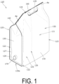
- the spout pouch 110 accommodates liquid contents, such as drinking water or a liquid detergent, and is configured, as illustrated in FIG. 1 , to dispense the liquid contents from a spout 170 attached to a side surface of a pouch main body 120 in a state of being placed with a pouch bottom portion 120a down during usage.
- liquid contents such as drinking water or a liquid detergent
- the spout pouch 110 includes the pouch main body 120 formed into a bag shape by thermally fusing films 130, 140, 150 having flexibility to form bag-making sealing portions, an inner side film 160 disposed inside the pouch main body 120, and the spout 170 attached to the pouch main body 120.
- the spout pouch 110 is accommodated and utilized in an outer case (not illustrated) during usage, during display, or during transport.
- the pouch main body 120 is configured as a so-called transverse gusset-type pouch with gusset portions formed on both side portions and, as illustrated in FIG. 1 and FIG. 2 , includes the spout attachment film 130 to which the spout 170 is attached, two side films 140 connected to the spout attachment film 130 by first connection seals 122 formed on both sides of the spout attachment film 130 in a transverse direction Xa, and a second film 150 disposed facing the spout attachment film 130 with a liquid contents accommodating portion 121 interposed therebetween and connected to the side films 140 by second connection seals 123 formed on both sides in the transverse direction Xa.
- the films 130, 140, 150, 160 are each formed as a resin film having a thermal fusing layer on at least one side thereof, and disposed so that the thermal fusing layers face each other at locations where the films are thermally fused to each other.
- thermally fused regions of the films 130, 140, 150, 160 are indicated by shading.
- the spout attachment film 130 includes a flange facing region 131 where the flange 171 of the spout 170 faces the spout attachment film 130.
- the flange facing region 131 includes a first facing region 131a that is a portion closer to a first side (upper side in the present embodiment) than a center thereof in a longitudinal direction Ya (up-down direction in the present embodiment) and a second facing region 131b that is a portion closer to a second side (lower side in the present embodiment) than the center thereof in the longitudinal direction.
- the spout attachment film 130 includes a spout through-hole 132 formed penetrating in a front-rear direction.
- the pouch main body 120 includes the first connection seal 122 formed by thermally fusing both sides of the spout attachment film 130 in the transverse direction Xa to the side films 140, the second connection seal 123 formed by thermally fusing both sides of the second film 150 in the transverse direction Xa to the side films 140, a top seal 124 formed by thermally fusing the films 140, 160 at a position corresponding to a top portion of the pouch main body 120 facing a bottom seal 125 with the liquid contents accommodating portion 121 interposed therebetween, the bottom seal 125 formed by thermally fusing the films 140, 160 at a position corresponding to the pouch bottom portion 120a of the pouch main body 120, and an intermediate seal 126 formed by thermally fusing the side films 140 and the inner side film 160.
- These seals 122 to 126 constitute bag-making sealing portions.
- connection seals 122, 123 respectively include seal base portions 122a, 123a having a strip shape extending in the longitudinal direction Ya, first inclined portions 122b, 123b formed on a first side (upper side) of the seal base portions 122a, 123a in the longitudinal direction Ya, and second inclined portions 122c, 123c formed on a second side (lower side) of the seal base portions 122a, 123a in the longitudinal direction Ya.
- the seal base portions 122a, 123a each include an inner side edge extending linearly in the longitudinal direction Ya.
- the first inclined portions 122b, 123b each include an inner side edge inclined with respect to the longitudinal direction Ya (at 45° in the present embodiment) inwardly in the transverse direction Xa toward the first side (upper side).
- the second inclined portions 122c, 123c each include an inner side edge inclined with respect to the longitudinal direction Ya (at 45° in the present embodiment) inwardly in the transverse direction Xa toward the second side (lower side).
- portions are formed in which the films 130, 140 are partially removed, and the side films 140 are thermally fused together. As a result, the side films 140 are prevented from being separated from each other at the predetermined locations described above (e.g., the locations Aa illustrated in FIG. 1 ).
- the pouch main body 120 includes first shape control sealing portions 127 as shape control sealing portions formed by fusing portions of the spout attachment film 130 positioned inward of the first connection seal 122 in the transverse direction Xa and portions of the side films 140.
- the first shape control sealing portions 127 are formed so as to continuously protrude inward in the transverse direction Xa from each first connection seal 122 (seal base portion 122a) on both sides in the transverse direction Xa with the flange facing region 131 (flange 171) interposed therebetween.
- the first shape control sealing portion 127 includes a portion positioned in a region between the flange facing region 131 and the first connection seal 122 in the transverse direction Xa, more specifically, a portion positioned in a region between the first facing region 131a on the first side (upper side) of the flange facing region 131 and the first connection seal 122 in the transverse direction Xa, and does not include a portion positioned in a region between the second facing region 131b on the second side (lower side) of the flange facing region 131 and the first connection seal 122 in the transverse direction Xa.
- first shape control sealing portions 127 formed in this way, it is possible to move the first facing region 131a side of the flange 171 fixed to the spout attachment film 130 to a pouch inner side, move the second facing region 131b side of the flange 171 to a pouch outer side, and adjust an inclination of the flange 171 so that the spout 170 faces the first side (upper side). Further, with the inclination of the flange 171 adjusted in this way, it is possible to suppress the occurrence of a buckling-induced portion that tends to be formed in the vicinity of an end portion on the second side (lower side) of the seal base portion 122a of the first connection seal 122.
- the first shape control sealing portion 127 may be formed so as to further include a portion positioned in a region between the second facing region 131b on the second side (lower side) of the flange facing region 131 and the first connection seal 122 in the transverse direction Xa in addition to the portion positioned in a region between the first facing region 131a on the first side (upper side) of the flange facing region 131 and the first connection seal 122 in the transverse direction Xa.
- the first shape control sealing portion 127 includes an innermost top portion 127a positioned innermost in the transverse direction Xa, a first inner side edge portion 127b formed continuously with a first side (upper side) of the innermost top portion 127a in the longitudinal direction Ya, and a second inner side edge portion 127c formed continuously with a second side (lower side) of the innermost top portion 127a in the longitudinal direction Ya.
- the first inner side edge portion 127b is formed at an incline outwardly in the transverse direction Xa toward the first side (upper side) in the longitudinal direction Ya.
- the second inner side edge portion 127c is formed at an incline outwardly in the transverse direction Xa toward the second side (lower side) in the longitudinal direction Ya.
- the innermost top portion 127a is formed in a dot shape (top dot shape).
- the innermost top portion 127a may be formed with a length in the longitudinal direction Ya, in other words, with an inner edge portion linearly extending in the longitudinal direction Ya.
- a curvature radius (R) of the inner edge portion in the vicinity of the innermost top portion 127a is preferably set to 20 mm or greater as a countermeasure against pouch breakage.
- the inner side edge portions 127b, 127c are each formed in a curved shape protruding inward in the transverse direction Xa, but the specific mode may be any mode.
- the inner side edge portions 127b, 127c may each be formed in a linear shape, may be formed in a curved shape protruding outward in the transverse direction Xa, or may be formed by combining one or more of the curved lines having a protruding shape or a recessed shape and the straight lines described above as desired.
- the curvature radius (R) thereof is preferably set to 20 mm or greater.
- the pouch main body 120 includes second shape control sealing portions 128 as shape control sealing portions formed by fusing portions of the spout attachment film 130 positioned inward of the first connection seal 122 in the transverse direction Xa and portions of the side films 140 in areas closer to the second side (lower side) in the longitudinal direction Ya than the first shape control sealing portions 127.
- the second shape control sealing portion 128 is formed at an interval from the first shape control sealing portion 127 in the longitudinal direction Ya.
- the second shape control sealing portions 128 are formed so as to continuously protrude inward in the transverse direction Xa from each first connection seal 122 (seal base portion 122a) on both sides of the flange facing region 131 (flange 171) in the transverse direction Xa.
- the second shape control sealing portion 128 includes a portion positioned in a region between the second facing region 131b on the second side (lower side) of the flange facing region 131 in the transverse direction Xa and the first connection seal 122, and does not include a portion positioned in a region between the first facing region 131a on the first side (upper side) of the flange facing region 131 in the transverse direction Xa and the first connection seal 122.
- the second shape control sealing portion 128 formed in this way, it is possible to move the first facing region 131a side of the flange 171 fixed to the spout attachment film 130 to the pouch outer side, move the second facing region 131b side of the flange 171 to the pouch inner side, and adjust the inclination of the flange 171 so that the spout 170 faces the second side (lower side).
- the second shape control sealing portions 128 may be formed so as to further include a portion positioned in a region between the first facing region 131a on the first side (upper side) of the flange facing region 131 and the first connection seal 122 in the transverse direction Xa in addition to the portion positioned in the region between the second facing region 131b on the second side (lower side) of the flange facing region 131 and the first connection seal 122 in the transverse direction Xa.
- the second shape control sealing portion 128 includes an innermost top portion 128a positioned innermost in the transverse direction Xa, a first inner side edge portion 128b formed continuously with a first side (upper side) of the innermost top portion 128a in the longitudinal direction Ya, and a second inner side edge portion 128c formed continuously with a second side (lower side) of the innermost top portion 128a in the longitudinal direction Ya.
- the first inner side edge portion 128b is formed at an incline outwardly in the transverse direction Xa toward the first side (upper side) in the longitudinal direction Ya.
- the second inner side edge portion 128c is formed at an incline outwardly in the transverse direction Xa toward the second side (lower side) in the longitudinal direction Ya.
- the innermost top portion 128a is formed in a dot shape (top dot shape).
- the innermost top portion 128a may be formed with a length in the longitudinal direction Ya, in other words, with an inner edge portion linearly extending in the longitudinal direction Ya.
- a curvature radius (R) of the inner edge portion in the vicinity of the innermost top portion 128a is preferably set to 20 mm or greater as a countermeasure against pouch breakage.
- the second shape control sealing portion 128 is formed at a predetermined interval from the first shape control sealing portion 127 in the longitudinal direction Ya.
- the first shape control sealing portion 127 and the second shape control sealing portion 128 may be formed continuously in the longitudinal direction Ya and, in this case, the shape control sealing portions 127, 128 may be formed so that an inner edge of the connecting portion of the first shape control sealing portion 127 and the second shape control sealing portion 128 is positioned inward of the first connection seal 122 (seal base portion 122a) in the transverse direction Xa.
- the inner side edge portions 128b, 128c are each formed in a curved shape protruding inward in the transverse direction Xa, but the specific mode may be any mode.
- the inner side edge portions 128b, 128c may each be formed in a linear shape, may be formed in a curved shape protruding outward in the transverse direction Xa, or may be formed by combining one or more of the curved lines having a protruding shape or a recessed shape or the straight lines described above as desired.
- the curvature radius (R) thereof is preferably set to 20 mm or greater.
- the spout 170 is formed of a synthetic resin or the like and is attached to the pouch main body 120 to function as a dispensing outlet for the liquid contents.
- the spout 170 is attached at a position closer to the second side (lower side) than a center of the spout attachment film 130 in the longitudinal direction Ya.
- the spout 170 includes a flange 171 disposed facing the spout attachment film 130 and, in the present embodiment, the flange 171 is formed as an area having a disk shape with a through-hole formed at a center thereof and an outer peripheral edge having a circular shape, and is disposed on an inner side of the pouch main body 120 and fixed to an inner side surface of the spout attachment film 130 by thermal fusing.
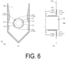
- FIG. 1 and FIG. 6 only a portion of the spout 170 is illustrated, and most of the spout 170 is disposed outside the pouch main body 120.
- the flange 171 includes a flange fixing portion 172 having an annular shape (circular shape in the present embodiment) and fixed to the spout attachment film 130 by thermal fusing, a flange buffering portion 173 formed in at least a partial region of an outer periphery of the flange fixing portion 172 and not fixed to the spout attachment film 130, an outer peripheral side non-fixed portion 174 formed in a partial region of the outer periphery of the flange fixing portion 172 and not fixed to the spout attachment film 130, and an inner peripheral side non-fixed portion 175 having an annular shape (circular shape in the present embodiment), set on an inner peripheral side of the flange fixing portion 172, and not fixed to the spout attachment film 130.
- a flange fixing portion 172 having an annular shape (circular shape in the present embodiment) and fixed to the spout attachment film 130 by thermal fusing
- a flange buffering portion 173 formed in at least a partial region
- the flange buffering portion 173 is an area of a portion of the outer periphery of the flange fixing portion 172 that is not fixed to the spout attachment film 130 and, as illustrated in FIG. 6 , is formed to a radial direction width Wa3 that is 20 to 80% (preferably 30 to 80%, even more preferably 45 to 80%) of a radial direction width Wa1 of the flange facing region 131 (that is, in the example illustrated in FIG.
- the spout attachment film 130 bends at a location corresponding to the outer peripheral edge of the flange 171 when the spout attachment film 130 moves toward the pouch inner side relative to the flange 171, and the spout attachment film 130 bends at a location corresponding to an outer peripheral edge of the flange fixing portion 172 when the spout attachment film 130 moves toward the pouch outer side relative to the flange 171 as illustrated in FIG. 7(a) , making it possible to keep a bending load from acting on a specific location of the spout attachment film 130.
- the radial direction width Wa3 of the flange buffering portion 173 is greater than 80% of the radial direction width Wa1
- the radial direction width Wa2 of the flange fixing portion 172 becomes too narrow, the fixing strength of the flange 171 to the spout attachment film 130 cannot be sufficiently ensured, and the fixed portion readily peels off due to impact or the like, which is not desirable.
- the radial direction width Wa2 of the flange fixing portion 172 is preferably set to 2 mm or greater (more preferably 3 mm or greater) in order to ensure the fixing strength.
- a relationship between a thickness of the spout attachment film 130 and the radial direction width Wa3 of the flange buffering portion 173 is preferably such that the radial direction width Wa3 is set larger when the thickness of the spout attachment film 130 is larger.
- the flange buffering portion 173 is formed at a position including a portion of the outer periphery of the flange fixing portion 172 facing the first side (upper side) in the longitudinal direction Ya at the center in the transverse direction Xa.
- the flange buffering portion 173 is also formed at a position including a portion of the outer periphery of the flange fixing portion 172 facing the second side (lower side) in the longitudinal direction Ya at the center in the transverse direction Xa.
- the flange buffering portion 173 is formed with a radial direction width that is not constant, the flange buffering portion 173 includes a wide portion 173a that is widest in the radial direction in the flange buffering portion 173, and this wide portion 173a of the flange buffering portion 173 on the first side (upper side) is formed at a position including a portion of the outer periphery of the flange fixing portion 172 that is facing the first side (upper side) in the longitudinal direction Ya at the center in the transverse direction Xa.
- the wide portion 173a of the flange buffering portion 173 on the second side (lower side) is formed at a position including a portion of the outer periphery of the flange fixing portion 172 that is facing the second side (lower side) in the longitudinal direction Ya at the center in the transverse direction Xa.
- the wide portion 173a of the flange buffering portion 173 on the first side (upper side) and the wide portion 173a of the flange buffering portion 173 on the second side (lower side) are formed to the same radial direction widths, but may be formed to different radial direction widths.
- the flange fixing portion 172 is set in an area of the flange 171 where the thickness on the outer peripheral side is thinly formed.
- the outer peripheral side non-fixed portion 174 is a portion of the outer periphery of the flange fixing portion 172 that is not fixed to the spout attachment film 130, does not exhibit the above-described effect of the flange buffering portion 173 (effect of keeping a bending load from acting on a specific location of the spout attachment film 130), and is formed with a narrower radial direction width than that of the flange buffering portion 173.
- the outer peripheral non-fixed portion 174 functions as an area that suppresses leakage (protrusion) of the adhesive outside the outer peripheral edge of the flange 171 and prevents the spout attachment film 130 from being fixed to the flange 171 in a state in which the spout attachment film 130 is wrinkled in the vicinity of the outer peripheral edge of the flange 171.
- the flange buffering portion 173 is described as being formed at two locations, namely on the first side (upper side) and on the second side (lower side) of the outer periphery of the flange fixing portion 172, but the specific mode of the flange buffering portion 173 is not limited thereto, and the flange buffering portion 173 may be formed in any desired mode in accordance with the embodiment.
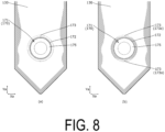
- the flange buffering portion 173 may be formed at only one of the two locations of the first side (upper side) and the second side (lower side) of the outer periphery of the flange fixing portion 172, or the flange buffering portion 173 may be formed across the entire outer periphery of the flange fixing portion 172 as illustrated in FIG. 8(a) .
- the flange buffering portion 173 is formed with a uniform radial direction width across the entire outer periphery of the flange fixing portion 172.
- FIG. 8(a) the flange buffering portion 173 is formed with a uniform radial direction width across the entire outer periphery of the flange fixing portion 172.
- a region in which the outer peripheral side non-fixed portion 174 is not formed (that is, a region fixed to the spout attachment film 130 up to the outer peripheral edge of the flange 171) may be formed in a partial region of the outer periphery of the flange fixing portion 172.
- the flange 171 of the spout 170 has been described as being formed in a flat plate shape.
- the flange buffering portion 173 includes the retracted portion 176 with an outer peripheral side tip portion positioned on a side (right side in FIG. 9 ) farther away from the spout attachment film 130 than the flange fixing portion 172 in a thickness direction.
- the retracted portion 176 is formed by curving the outer peripheral side of the flange 171 away from the spout attachment film 130 (right side in FIG. 9 ), and includes a curved surface 176a that curves toward the side away from the spout attachment film 130 (right side in FIG. 9 ) toward the outer peripheral side, on the side facing the spout attachment film 130.
- the curved surface 176a curves, forming a protruding shape toward the side facing the spout attachment film 130 (left side in FIG. 9 ).
- the retracted portion 176 may be formed in an annular shape across the entire periphery of the outer peripheral portion of the flange 171, or may be formed only in a partial region of the outer peripheral portion of the flange 171. Further, in a case in which the retracted portion 176 is formed only in a partial region of the outer peripheral portion of the flange 171, the retracted portion 176 may be formed at a plurality of locations separated in the peripheral direction.
- a dimensional (width) relationship and a positional relationship between the flange buffering portion 173 and the retracted portion 176 in the peripheral direction need only be such that the dimensions (widths) and the positions of the flange buffering portion 173 and the retracted portion 176 in the peripheral direction are set so that the flange buffering portion 173 and the retracted portion 176 overlap each other in the peripheral direction in at least a partial region of the outer peripheral portion of the flange 171.
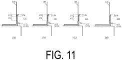
- a radial direction dimension relationship between the flange buffering portion 173 and the retracted portion 176 may be set so that the dimensions (widths) in the radial direction of the flange buffering portion 173 and the retracted portion 176 coincide with each other as illustrated in FIG. 11(a)
- the dimension (width) in the radial direction of the retracted portion 176 may be set larger than that of the flange buffering portion 173 as illustrated in FIG. 11(b)
- the dimension (width) in the radial direction of the retracted portion 176 may be set smaller than that of the flange buffering portion 173 as illustrated in FIG. 11(c) .
- an outer peripheral edge position of the flange buffering portion 173 and an outer peripheral edge position of the retracted portion 176 coincide with each other.
- the retracted portion 176 has a shape in which the outer peripheral side of the flange 171 is curved to the side away from the spout attachment film 130 (right side in FIG. 9 ), but the specific shape of the retracted portion 176 may be any shape as long as the outer peripheral side tip end portion of the flange fixing portion 172 is positioned away from the spout attachment film 130 (right side in FIG. 9 ).
- the retracted portion 176 may be formed in a shape in which the flange 171 is not curved but the flange 171 is bent in the middle in the radial direction.
- the inner side film 160 is formed as a resin film having a rectangular shape (or substantially rectangular shape) and flexibility with a thermal fusing layer on at least one side thereof and, as understood from FIG. 1 and FIG. 2 , is disposed in the pouch main body 120 (liquid contents accommodating portion 121) in a state of being folded in two, and a predetermined portion thereof is thermally fused to the side film 140.
- the inner side film 160 is formed with a plurality of film penetrating portions formed in hole shapes penetrating in the film thickness direction.
- a handle hole 129 for a user to hold the spout pouch 110 by passing his or her hand or finger therethrough is formed through the overlapping portion of the films 140, 160.
- a transverse direction dimension ba1 from the first connection seal 122 (seal base portion 122a) to the innermost top portion 127a of the first shape control sealing portion 127 is preferably set to 6 to 10% of a transverse direction interval aa to the first connection seal 122 (seal base portion 122a) in the transverse direction Xa.
- the transverse direction dimension ba1 is preferably set to 20 to 50% of a transverse direction dimension ca from the first connection seal 122 (seal base portion 122a) to, of the outer peripheral edge of the flange facing region 131 (flange 171), a location 131c positioned on the outermost side (first connection seal 122 side) in the transverse direction Xa.
- the effects of forming the first shape control sealing portion 127 (the effect of deepening the spout attachment film 130 in the vicinity of the outer peripheral edge of the flange 171 toward the pouch inner side, the effect of alleviating the tension of the spout attachment film 130 in the vicinity of the outer peripheral edge of the flange 171, and the effect of adjusting the inclination of the flange 171) while avoiding excessive restraint of the movement of the spout 170 by the spout attachment film 130.
- a transverse direction dimension ba2 from the first connection seal 122 (seal base portion 122a) to the innermost top portion 128a of the second shape control sealing portion 128 is set to 4 to 10% of the transverse direction interval aa.
- transverse direction dimension ba2 is preferably set to 10 to 50% of the transverse direction dimension ca.
- the effects of forming the second shape control sealing portion 128 (the effect of deepening the spout attachment film 130 in the vicinity of the outer peripheral edge of the flange 171 toward the pouch inner side, the effect of alleviating the tension of the spout attachment film 130 in the vicinity of the outer peripheral edge of the flange 171, and the effect of adjusting the inclination of the flange 171) while avoiding excessive restraint of the movement of the spout 170 by the spout attachment film 130.
- transverse direction dimension ba1 is preferably set to the transverse direction dimension ba2 or greater.
- transverse direction dimension ba2 is preferably set to 30% or more of the transverse direction dimension ba1.
- the inclination of the spout 170 can be favorably adjusted, that is, the inclination of the spout 170 toward the first side (upper side) or the second side (lower side) in the longitudinal direction Ya can be favorably adjusted.
- a longitudinal direction position of the innermost top portion 127a of the first shape control sealing portion 127 is preferably set within a range of ⁇ 10 mm in the longitudinal direction Ya from the longitudinal direction position of a location 131d of the outer peripheral edge of the flange facing region 131 (flange 171) positioned closest to the first side (upper side) in the longitudinal direction Ya.
- the longitudinal direction position of the innermost top portion 127a of the first shape control sealing portion 127 is shifted to either the first side (upper side) or the second side (lower side) from the longitudinal direction position of the location 131d.
- a longitudinal direction position of an end portion (lower end) on the second side (lower side) of the first shape control sealing portion 127 (second inner side edge portion 127c) is preferably set at a position lateral of the flange facing region 131 (flange 171) in the transverse direction Xa, more preferably within a range of ⁇ 10 mm in the longitudinal direction Ya from a center position of the flange facing region 131 (flange 171) in the longitudinal direction Ya, and more preferably set to coincide with the center position of the flange facing region 131 (flange 171) in the longitudinal direction Ya.
- a longitudinal direction position of an end portion (upper end) on the first side (upper side) of the second shape control sealing portion 128 (first inner side edge portion 128b) is set lower than the center position of the flange facing region 131 (flange 171) in the longitudinal direction Ya.
- the spout attachment film 130 (first connection seal 122) is folded starting from the lower end portions of the second shape control sealing portions 128 (the second inner side edge portions 128c) on both sides in the transverse direction Xa.
- a longitudinal direction position of the end portion (upper end) on the first side (upper side) of the second shape control sealing portion 128 (first inner side edge portion 128b) is more preferably set to a position located lateral of the flange facing region 131 (second facing region 131b) in the transverse direction Xa, as illustrated in FIG. 5(a) .
- the spout attachment film 130 and the spout 170 are guided to the state shown in FIG. 5(b) , making it possible to prevent the spout 170 from retracting to the pouch inner side and causing a strong force to act on the spout 170 due to contact with the floor or the like.
- a longitudinal direction dimension sa (longitudinal direction dimension sa of the first inner side edge portion 127b) from the innermost top portion 127a of the first shape control sealing portion 127 to an end portion (upper end) on the first side (upper side) of the first shape control sealing portion 127 (first inner side edge portion 127b) is preferably set larger than a longitudinal direction dimension ta (longitudinal direction dimension ta of the second inner side edge portion 127c) from the innermost top portion 127a of the first shape control sealing portion 127 to the end portion (lower end) on the second side (lower side) of the first shape control sealing portion 127 (second inner side edge portion 127c).
- the longitudinal direction dimension sa and the transverse direction dimension ba1 are preferably set so that an angle between the first connection seal 22 and a virtual line connecting the innermost top portion 127a of the first shape control sealing portion 127 (end portion on the first side of the innermost top portion 127a in a case in which the innermost top portion 127a is formed with a length in the longitudinal direction Ya) and the end portion (upper end) on the first side (upper side) of the first shape control sealing portion 127 (first inner side edge portion 127b) is 5 to 10°.
- a longitudinal direction position of the innermost top portion 128a of the second shape control sealing portion 128 (longitudinal direction position of an end portion on the first side of the innermost top portion 128a in a case in which the innermost top portion 127a is formed with a length in the longitudinal direction Ya) is preferably set within a range of ⁇ 5 mm in the longitudinal direction Ya from the longitudinal direction position of a location 131e of the outer peripheral edge of the flange facing region 131 (flange 171) positioned closest to the second side (lower side) in the longitudinal direction Ya (or from a location of the outer peripheral edge of the flange fixing portion 172 positioned closest to the second side in the longitudinal direction Ya).
- the longitudinal direction position of the innermost top portion 128a of the second shape control sealing portion 128 is preferably shifted to either the first side (upper side) or the second side (lower side) from the longitudinal direction position of the location 131e.
- the spout attachment film 130 and the spout 170 can be smoothly guided to the state shown in FIG. 5(b) described above.
- a longitudinal direction position of an end portion (lower end) on the second side (lower side) of the second shape control sealing portion 128 (second inner side edge portion 128c) is preferably set on the first side (upper side) of the second inclined portion 122c of the first connection seal 122.
- the second shape control sealing portion 128 is a portion constituting the pouch bottom portion 120a.
- the second shape control sealing portion 128 is a portion constituting the pouch bottom portion 120a.
- spout pouch 110 may be configured by any combination of configurations of the embodiment described above and modified examples to be described below.
- the spout pouch 110 is described as being accommodated and utilized in the outer case (not illustrated) during usage, during display, or during transport, but the spout pouch 110 itself may be used or may be displayed or transported without being accommodated in the outer case (not illustrated).
- each film includes a layer having thermal fusing properties, such as an olefin-based layer made of low density polyethylene or polypropylene or a polyester-based layer made of polyethylene terephthalate (PET), or the like on at least one of the surfaces thereof
- a film including a single film of the thermal fusing layer may be used, or any desired layer may be layered to the thermal fusing layer.
- Any material may be used as a material constituting the multilayer, and the multilayer may be formed as desired by layering a known polyester such as PET or polybutylene terephthalate (PBT), polypropylene, polyamide, polyethylene, aluminum foil, or the like.
- the pouch main body 120 is described as being formed of four films, namely the films 130, 140, 150.
- a specific mode of the pouch main body 120 such as the number of films constituting the pouch main body 120, is not limited to the above and, for example, a gusset film for the bottom portion may be separately provided at a position corresponding to the pouch bottom portion 120a.
- the inner side film 160 need not be provided.
- the spout pouch 110 is configured as a large-capacity pouch having a volume of 2 to 5 L
- the spout 170 is configured as a large spout with an outer diameter of the flange 171 being 50 to 70 mm.
- the sizes of the spout pouch 110 and the spout 170 are not limited thereto and may be set as desired in accordance with the embodiment.
- the spout attachment film 130 to which the spout 170 is attached is described as a gusset film constituting a gusset portion of a transverse gusset-type pouch.
- a specific mode of the spout attachment film 130 is not limited thereto and, for example, the spout attachment film 130 may be a gusset film disposed on a top portion or a bottom portion of the pouch, or the spout attachment film 130 may be a film other than a gusset film.
- the shape control sealing portions 127, 128 are described as being formed continuously with the first connection seal 122. However, the shape control sealing portions 127, 128 may be formed independently of (at positions separated from) the first connection seal 122.
- first shape control sealing portion 127 is described as being formed on each of both sides of the flange facing region 131, but the first shape control sealing portion 127 may be formed on only one of both sides of the flange facing region 131 in the transverse direction Xa.
- second shape control sealing portion 128 may be formed on only one of both sides of the flange facing region 131 in the transverse direction Xa.
- the shape control sealing portions 127, 128 on both sides in the transverse direction Xa are formed in line symmetry (left-right symmetry) with respect to a virtual line extending in the longitudinal direction Ya at the center of the spout attachment film 130 in the transverse direction Xa, but the configuration is not limited thereto.
- the first connection seals 122 on both sides in the transverse direction Xa are formed in line symmetry (left-right symmetry) with respect to the virtual line, but are not limited thereto.
- the first shape control sealing portion 127 and the second shape control sealing portion 128 are described as being formed. However, only the first shape control sealing portion 127 may be formed without forming the second shape control sealing portion 128. Note that, in a case in which only the first shape control sealing portion 127 is formed, the dimensional relationship of each portion related to the first shape control sealing portion 127 is the same as that described above with reference to FIG. 4 . Alternatively, only the second shape control sealing portion 128 may be formed without forming the first shape control sealing portion 127. Note that, in a case in which only the second shape control sealing portion 128 is formed, the dimensional relationship of each portion related to the second shape control sealing portion 128 is the same as that described above with reference to FIG. 4 .
- the flange 171 is described as being formed in a disk shape with an outer peripheral edge having a circular shape.
- the specific shape of the flange 171 may be any shape such as a shape having an outer peripheral edge of a shape other than a circular shape, such as a rectangular shape or a polygonal shape.
- the flange 171 is described as being fixed to the inner side surface of the spout attachment film 130. However, the flange 171 may be fixed to the outer side surface of the spout attachment film 130.
- the flange 171 may be fixed to the spout attachment film 130 by any method other than thermal fusing, such as adhesion.
- the flange 171 is described as being provided with the flange buffering portion 173.
- the flange 171 may be fixed to the spout attachment film 130 in any manner, the flange 171 may not be provided with the flange buffering portion 173 and, for example, the entire region of the flange 171 may be fixed to the spout attachment film 130.
- first shape control sealing portion 127 and the second shape control sealing portion 128 are described as being formed in the first connection seal 122. However, the shape control sealing portions 127, 128 need not be formed.
- top portion bottom portion
- side portion side portion
- up and down directions are used herein, but these terms do not limit the orientation of the placement of the spout pouch 110 during display, during transport, and the like.
- the spout pouch 110 may be placed on the placement surface with the side portion or the top portion of the spout pouch 110 down during display, during transport, and the like.
- the spout pouch 210 accommodates liquid contents, such as drinking water or a liquid detergent, and is configured to dispense the liquid contents from a spout 280 attached to a side surface of a pouch main body 220 as illustrated in FIG. 12 and FIG. 18 .
- the spout pouch 210 includes the pouch main body 220 formed into a bag shape by thermally fusing films 230, 240, 250, 260 having flexibility to form bag-making sealing portions, an inner side film 270 disposed inside the pouch main body 220, and the spout 280 attached to the pouch main body 220.
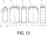
- the pouch main body 220 is configured as a so-called transverse gusset-type pouch with gussets formed on both side portions and, as illustrated in FIG. 12 and FIG. 13 , includes the front side film 230 and the rear side film 240 disposed facing each other in a front-rear direction Xb with a liquid contents accommodating portion 221 interposed therebetween, the side gusset film 250 disposed between the front side film 230 and the rear side film 240 of one pouch side portion and thermally fused to the front side film 230 and the rear side film 240 by a first side seal 222, and the second gusset film 260 disposed facing the side gusset film 250 in a front-back direction Zb with the liquid contents accommodating portion 221 interposed therebetween and thermally fused to the front side film 230 and the rear side film 240 by a second side seal 223 of the other pouch side portion.
- the films 230, 240, 250, 260, 270 are each formed as a resin film having a thermal fusing layer on at least one side thereof, and disposed so that the thermal fusing layers face each other at locations where the films are thermally fused to each other.
- thermally fused regions of the films 230, 240, 250, 260, and 270 are indicated by shading.
- the pouch main body 220 includes the first side seal 222 formed by thermally fusing both sides of the side gusset film 250 in the transverse direction to the films 230, 240, the second side seal 223 formed by thermally fusing both sides of the second gusset film 260 in the transverse direction to the films 230, 240, a top seal 224 formed by thermally fusing the films 230, 240, 260 at a position corresponding to a top portion of the pouch main body 220 facing a bottom seal 225 with the liquid contents accommodating portion 221 interposed therebetween, the bottom seal 225 formed by thermally fusing the films 230, 240, 260 at a position corresponding to a pouch bottom portion 220a of the pouch main body 220, and an intermediate seal 226 formed by thermally fusing the films 230, 240 and the inner side film 270.
- These seals 222 to 226 constitute bag-making sealing portions.
- portions are formed where the second gusset film 260 is partially removed, and the films 230, 240 are thermally fused together. As a result, the films 230, 240 are prevented from being separated from each other at the predetermined locations (e.g., locations A illustrated in FIG. 12 ).
- the side gusset film 250 includes a front side sealing region 251 thermally fused to the front side film 230 at the first side seal 222, a rear side sealing region 252 thermally fused to the rear side film 240 at the first side seal 222, and a non-sealing region 253 that is a region on an inner side of the front side sealing region 251 and the rear side sealing region 252.
- the non-sealing region 253 includes a front side outer edge 254 that is a boundary with the front side sealing region 251, and a rear side outer edge 255 that is a boundary with the rear side sealing region 252.
- the side gusset film 250 is formed in line symmetry (left-right symmetry) with respect to a virtual line extending in an up-down direction Yb at a center of the side gusset film 250 in the front-rear direction Xb.
- the front side outer edge 254 and the rear side outer edge 255 are formed in line symmetry (left-right symmetry) with respect to the virtual line.
- the front side outer edge 254 and the rear side outer edge 255 include base edge portions 254a, 255a spaced apart from each other in the front-rear direction Xb, lower side inclined edge portions 254b, 255b extending from lower ends of the base edge portions 254a, 255a to a lower end coupling portion 253a coupling lower ends of the front side outer edge 254 and the rear side outer edge 255, and upper side inclined edge portions 254c, 255c extending from the upper ends of the base edge portions 254a, 255a to an upper end coupling portion 253b coupling upper ends of the front side outer edge 254 and the rear side outer edge 255.
- the base edge portions 254a, 255a are formed linearly extending in the up-down direction Yb.
- the lower side inclined edge portions 254b, 255b extend linearly at an incline in the up-down direction Yb inwardly in the front-rear direction Xb (at an inclination angle of 45° in the present embodiment) toward the lower side.
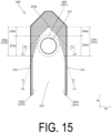
- the upper side inclined edge portions 254c, 255c are constituted by at least two inclined portions having different inclination angles relative to the up-down direction Yb and, in the present embodiment, as illustrated in FIG. 15 , include gently inclined portions 254d, 255d that connect the upper ends of the base edge portions 254a, 255a with portions above and inward, in the front-rear direction Xb, of the upper ends of the base edge portions 254a, 255a, and steeply inclined portions 254e, 255e that connect upper ends of the gently inclined portions 254d, 255d with the upper end coupling portion 253b.
- each of the gently inclined portions 254d, 255d is constituted by one linear portion extending at an incline in the up-down direction Yb inwardly in the front-rear direction Xb toward the upper side
- each of the steeply inclined portions 254e, 255e is constituted by one linear portion extending at an incline in the up-down direction Yb inwardly in the front-rear direction Xb toward the upper side (at an inclination angle of 45° in the present embodiment).
- first virtual lines Lb1 passing through the upper ends and the lower ends of the gently inclined portions 254d, 255d extend at an incline in the up-down direction Yb inwardly in the front-rear direction Xb toward the upper side.
- second virtual lines Lb2 passing through upper and lower ends of the steeply inclined portions 254e, 255e extend at an incline in the up-down direction Yb inwardly in the front-rear direction Xb toward the upper side.
- an inclination angle ⁇ 1 of the first virtual line Lb1 with respect to the up-down direction Yb is smaller than an inclination angle ⁇ 2 of the second virtual line Lb2 with respect to the up-down direction Yb.
- a degree of extending inwardly in the front-rear direction Xb toward the upper side is stronger (greater) for the second virtual lines Lb2 (steeply inclined portions 254e, 255e) than for the first virtual lines Lb1 (gently inclined portions 254d, 255d).
- the side gusset film 250 includes a flange facing region 256 where a flange 281 of the spout 280 faces the side gusset film 250.
- the flange facing region 256 is formed in an annular shape with an outer peripheral edge having a circular shape.
- the side gusset film 250 includes a spout through-hole 257 having a circular shape, formed so as to penetrate in the film thickness direction, and through which a dispensing cylindrical portion 282 of the spout 280 is inserted.
- the spout 280 is formed of a synthetic resin or other material, is attached to the pouch main body 220 to serve as a dispensing outlet for the liquid contents and, as illustrated in FIG. 12 and FIG. 18 , and includes the flange 281 disposed facing the side gusset film 250, the dispensing cylindrical portion 282 extending perpendicularly to the flange 281 having a disk shape and including a dispensing hole 282a formed therein, and a cap 283 detachably attached to a tip end of the dispensing cylindrical portion 282.
- the flange 281 is formed as an area having a disk shape (annular shape) with a through-hole formed at a center thereof and an outer peripheral edge having a circular shape (flange outer peripheral edge), is disposed on an inner side of the pouch main body 220, and is at least partially fixed to an inner side surface of the side gusset film 250 by thermal fusing.
- FIG. 12 illustrates only the flange 281 of the spout 280 and, as illustrated in FIG. 18 , most of the spout 280, such as the dispensing cylindrical portion 282 and the cap 283, is disposed outside the pouch main body 220.
- At least a portion (major portion in the example illustrated in FIG. 15 ) of the flange 281 (flange facing region 256) including a center of the flange 281 (flange facing region 256) is disposed facing a region between the upper side inclined edge portion 254c of the front side outer edge 254 and the upper side inclined edge portion 255c of the rear side outer edge 255, and more particularly, disposed facing a region between the gently inclined portion 254d of the front side outer edge 254 and the gently inclined portion 255d of the rear side outer edge 255.
- the flange 281 (flange facing region 256) is disposed at a center of the side gusset film 250 in the front-rear direction Xb, and an interval between the front side outer edge 254 and an outer edge of the flange 281 (flange facing region 256) and an interval between the rear side outer edge 255 and the outer edge of the flange 281 (flange facing region 256) in the front-rear direction Xb are equal.
- the region between the upper side inclined edge portion 254c of the front side outer edge 254 and the upper side inclined edge portion 255c of the rear side outer edge 255 to which the flange 281 is (at least partially) attached as described above is a portion inclined inwardly of the pouch main body 220 in the front-back direction Zb toward the upper side when viewed in the front-rear direction Xb in a state in which the spout pouch 210 is placed on a placement surface with the pouch bottom portion 220a down. Therefore, in a state in which the spout pouch 210 is placed on the placement surface, as understood from FIG. 12 and FIG.
- the dispensing cylindrical portion 282 of the spout 280 attached to the region described above is at an upward incline, extending obliquely with respect to the up-down direction Yb (and the front-back direction Zb), in other words, is inclined outwardly of the pouch main body 220 in the front-back direction Zb toward the upper side.
- the inner side film 270 is formed as a resin film having a rectangular shape (or substantially rectangular shape) and flexibility with a thermal fusing layer on at least one side thereof and, as understood from FIG. 12 and FIG. 13 , is disposed in the pouch main body 220 (liquid contents accommodating portion 221) in a state of being folded in two, and a predetermined portion thereof is thermally fused to the films 230, 240.
- the inner side film 270 is formed with a plurality of film penetrating portions formed in hole shapes penetrating in the film thickness direction.
- a handle hole 227 for a user to hold the spout pouch 210 by passing his or her hand or finger therethrough is formed through the overlapping portion of the films 230, 240, 260.
- FIG. 13 illustrates the handle hole 227 being formed in a state in which the films 230, 240, 260 are not thermally fused to one another for convenience of technical understanding.
- the handle hole 227 is formed by punching at a predetermined location after the films 230, 240, 260 are thermally fused to one another.
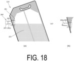
- the liquid contents accommodating portion 221 of the spout pouch 210 are accommodated in an amount equal to or less than the volume of a portion below a virtual line Lb3 obtained by extending a lower end edge of an inner peripheral surface of the dispensing hole 282a of the spout 280 (specifically, the lower end edge of the inner peripheral surface of the dispensing hole 282a on a tip end side of the dispensing cylindrical portion 282) of the liquid contents accommodating portion 221 in the extending direction of the lower end edge when the top seal 224 (pouch top portion side), including the handle hole 227 formed therein, is supported (held) and the spout pouch 210 accommodating the liquid contents in the liquid contents accommodating portion 221 is lifted up in an unopened state (liquid contents have not yet been dispensed), as viewed in the front-rear direction Xb.
- FIG. 18(a) illustrates a state in which the liquid contents accommodating portion 221 accommodates the same amount of
- the spout pouch 210 By setting the amount of the liquid contents accommodated in the liquid contents accommodating portion 221 in this way, it is possible to tilt and lift the spout pouch 210 so that the dispensing cylindrical portion 282 of the spout 280 is facing sideways (by holding the pouch top portion side with the handle hole 227 formed therein or the like) and make the dispensing cylindrical portion 282 extend in a horizontal direction or make the dispensing cylindrical portion 282 incline downward (that is, incline downward from the horizontal direction) when dispensing the liquid contents, as in the posture illustrated in FIG. 18(a) .
- an inclination angle of the flange 281 with respect to the up-down direction Yb of the pouch main body 220 by reducing an inclination angle of the region of the side gusset film 250 to which the flange 281 is attached (region between the gently inclined portions 254d, 255d) with respect to the up-down direction Yb, thereby adjusting the extending direction of the dispensing cylindrical portion 282 of the spout 280 (direction in which the virtual line Lb3 extends) downward (closer to a direction perpendicular to the up-down direction Yb).
- the gently inclined portions 254d, 255d are described as being constituted by one linear portion extending at an incline in the up-down direction Yb, but the specific mode of the gently inclined portions 254d, 255d is not limited thereto, and the gently inclined portions 254d, 255d may each be constituted by at least one linear portion, at least one curved portion, or a combination thereof.
- each of the gently inclined portions 254d, 255d includes a plurality of (three) linear portions, that is, a first linear portion extending at an incline in the up-down direction Yb inwardly in the front-rear direction Xb toward the upper side from the upper end of the base edge portion 254a, 255a, a second linear portion extending in the up-down direction Yb from an upper end of the first linear portion, and a third linear portion extending at an incline in the up-down direction Yb inwardly in the front-rear direction Xb toward the upper side from an upper end of the second linear portion.
- each of the gently inclined portions 254d, 255d is constituted by a plurality of (three) linear portions, that is, a first linear portion extending at an incline in the up-down direction Yb inwardly in the front-rear direction Xb toward the upper side from the upper end of the base edge portion 254a, 255a, a second linear portion extending at an incline in the up-down direction Yb outwardly in the front-rear direction Xb toward the upper side from the upper end of the first linear portion, and a third linear portion extending at an incline in the up-down direction Yb inwardly in the front-rear direction Xb toward the upper side from the upper end of the second linear portion.
- the linear portions (or curved portions) constituting the gently inclined portions 254d, 255d may extend at an incline in the up-down direction Yb inwardly in the front-rear direction Xb toward the upper side, may extend in the up-down direction Yb, may extend at an incline in the up-down direction Yb outwardly in the front-rear direction Xb toward the upper side, or the like.
- each of the steeply inclined portions 254e, 255e are constituted by one linear portion extending at an incline in the up-down direction Yb, but the specific mode of the steeply inclined portions 254e, 255e is not limited thereto, and the steeply inclined portions 254e, 255e may each be constituted by at least one linear portion, at least one curved portion, or a combination thereof.
- At least one of the front side sealing region 251 and the rear side sealing region 252 includes control sealing portions 251a, 252a positioned inward of the first virtual line L1 in the front-rear direction Xb.
- control sealing portions 251a, 252a are each formed so as to include a portion positioned in a region between a lower half of the flange facing region 256 (flange 281) and the front side sealing region 251 or the rear side sealing region 252 in the front-rear direction Xb, and not include a portion positioned above a center of the flange facing region 256 (flange 281) in the up-down direction Yb.
- each of the control sealing portions 251a, 252a positioned most inward in the front-rear direction Xb is positioned in a region between the lower half of the flange facing region 256 (flange 281) and the front side sealing region 251 or the rear side sealing region 252 in the front-rear direction Xb.
- control sealing portions 251a, 252a each include an area positioned below the flange facing region 256 (flange 281).
- spout pouch 210 may be configured by any combination of configurations of the embodiment described above and modified examples described below.
- the spout pouch 210 may be accommodated and utilized in the outer case (not illustrated) during usage, during display, or during transport thereof, and the spout pouch 210 itself may be used, displayed, or transported, without being accommodated in the outer case (not illustrated).
- each film includes a layer having thermal fusing properties, such as an olefin-based layer made of low density polyethylene or polypropylene or a polyester-based layer made of polyethylene terephthalate (PET), or the like on at least one of the surfaces thereof, a film including a single film of the thermal fusing layer may be used, or any desired layer may be layered to the thermal fusing layer.
- a layer having thermal fusing properties such as an olefin-based layer made of low density polyethylene or polypropylene or a polyester-based layer made of polyethylene terephthalate (PET), or the like
- PET polyethylene terephthalate
- any material may be used as a material constituting the multilayer, and the multilayer may be formed as desired by layering a known polyester such as PET or polybutylene terephthalate (PBT), polypropylene, polyamide, polyethylene, aluminum foil, or the like.
- PET polybutylene terephthalate
- PBT polybutylene terephthalate
- polypropylene polypropylene
- polyamide polyamide
- polyethylene polyethylene
- aluminum foil or the like.
- the pouch main body 220 is described as being formed of four films, namely the films 230, 240, 250 260.
- a specific mode of the pouch main body 220 such as the number of films constituting the pouch main body 220, is not limited to the above and, for example, a gusset film for the bottom portion may be separately provided at a position corresponding to the pouch bottom portion 220a.
- the inner side film 270 need not be provided.
- the spout pouch 210 is configured as a large-capacity pouch having a volume of 2 to 5 L
- the spout 280 is configured as a large spout with an outer diameter of the flange 281 being 50 to 70 mm.
- the sizes of the spout pouch 210 and the spout 280 are not limited thereto and may be set as desired in accordance with the embodiment.
- the front side outer edge 254 and the rear side outer edge 255 are described as being formed in line symmetry (left-right symmetry) with respect to the virtual line extending in the up-down direction Yb at the center of the side gusset film 250 in the front-rear direction Xb.
- the front side outer edge 254 and the rear side outer edge 255 may be formed not in left-right symmetry.
- control sealing portions 251a, 252a are formed continuously with the sealing regions 251, 252.
- control sealing portions 251a, 252a may be formed independently of (at positions separated from) the sealing regions 251, 252.
- the flange 281 is described as being formed in a disk shape with an outer peripheral edge having a circular shape.
- the specific shape of the flange 281 may be any shape such as a shape having an outer peripheral edge (flange outer peripheral edge) of a shape other than a circular shape, such as a rectangular shape or a polygonal shape.
- the flange 281 is described as being fixed to the inner side surface of the side gusset film 250.
- the flange 281 may be fixed to an outer side surface of the side gusset film 250.
- the flange 281 may be fixed to the side gusset film 250 by any method other than thermal fusing, such as adhesion.
- top portion bottom portion
- side portion side portion
- up and down directions are used herein, but these terms do not limit the orientation of the placement of the spout pouch 210 during display, during transport, and the like.
- the spout pouch 210 may be placed on the placement surface with the side portion or the top portion of the spout pouch 210 down during display, during transport, and the like.
- the liquid contents are described as being dispensed in a state in which the pouch top portion side is held and the spout pouch 210 is lifted, but the specific mode of dispensing the liquid contents is not limited to the above.
- the liquid contents may be dispensed in a state in which the spout pouch 210 is lifted by supporting and holding a portion other than the pouch top portion side such as the pouch bottom portion 220a, or the liquid contents may be dispensed in a state in which the spout pouch 210 is placed on a placement surface.
Landscapes
- Engineering & Computer Science (AREA)
- Mechanical Engineering (AREA)
- Bag Frames (AREA)
- Packages (AREA)
Abstract
Description
- The present invention relates to a spout pouch in which a spout is attached to a pouch main body.
- As a container for accommodating liquid contents, such as drinking water or a liquid detergent, there has been known use of a spout pouch in which a spout serving as an dispensing outlet is attached to a pouch main body formed by thermally fusing a plurality of resin films, and a spout pouch in which a spout is attached, in a transverse direction, to a side gusset film of a pouch main body formed by thermally fusing a plurality of films (e.g., see Patent Document 1 and Patent Document 2).
- Further, as a method of attaching a spout of such a spout pouch, there has also been generally known a method of arranging a flange of the spout so that the flange faces a spout attachment film, and fixing the flange to the spout attachment film by means such as thermal fusing.
-
- Patent Document 1:
JP 2012-121611 A - Patent Document 2:
JP 2020-132177 A - However, in the spout pouch in the known related art of Patent Document 1 and
Patent Document 2, the problem arises that, when the spout pouch is dropped or the like, the spout attachment film may be damaged in the vicinity of a flange outer peripheral edge due to a weight of the contents, breaking the pouch main body starting from the vicinity of the flange outer peripheral edge. - The breakage of the pouch main body is presumably caused by the spout rotating (tilting) with respect to the spout attachment film when the spout pouch is dropped, a moment load being applied to the vicinity of the flange outer peripheral edge, and the vicinity of the flange outer peripheral edge, with the moment load applied, striking the floor or the like.
- Further, in the spout pouch in the known related art of
Patent Document 2, in a usage mode in which the pouch is lifted to dispense the liquid contents or the like, the spout may unexpectedly move due to the weight of the liquid contents contained in the spout or the like at the time of dispensing the liquid contents, resulting in the problem that an orientation of a dispensing cylindrical portion of the spout is difficult to set, making it difficult to dispense the liquid contents. - The present invention has been made to solve these problems, and an object of the present invention is to provide a spout pouch that, with a simple configuration, improves an ease of dispensing liquid contents through a spout, and suppresses breakage of a pouch main body starting from the vicinity of a flange outer peripheral edge.
- The present invention solves the problems described above, in which a spout pouch includes a pouch main body and a spout attached to the pouch main body. The pouch main body includes a spout attachment film to which the spout is attached, and a side film connected to the spout attachment film by a connection seal formed on both sides of the spout attachment film in a transverse direction. The spout attachment film includes a flange facing region where a flange of the spout faces the spout attachment film. The pouch main body includes a shape control sealing portion formed by fusing a portion of the spout attachment film positioned inward of the connection seal in the transverse direction and the side film. The shape control sealing portion includes a portion positioned in a region between the flange facing region and the connection seal in the transverse direction.
- Further, The present invention further solves the problems described above, in which a spout pouch includes a front side film, a rear side film, a side gusset film disposed between the front side film and the rear side film at a pouch side portion and thermally fused to the front side film and the rear side film by a side seal, and a spout attached to the side gusset film. The side gusset film includes a front side sealing region thermally fused to the front side film at the side seal, a rear side sealing region thermally fused to the rear side film at the side seal, and a non-sealing region that is a region inward of the front side sealing region and the rear side sealing region. The non-sealing region includes a front side outer edge that is a boundary with the front side sealing region, and a rear side outer edge that is a boundary with the rear side sealing region. The front side outer edge and the rear side outer edge each include a base edge portion, the base edge portion of the front side outer edge and the base edge portion of the rear side outer edge being disposed spaced apart from each other in a front-rear direction, and an upper side inclined edge portion extending from an upper end of the base edge portion to an upper end coupling portion coupling an upper end of the front side outer edge and an upper end of the rear side outer edge. At least a portion of a flange of the spout is disposed facing a region between the upper side inclined edge portion of the front side outer edge and the upper side inclined edge portion of the rear side outer edge.
- The present invention further solves the above described problems, in which a spout pouch includes a pouch main body and a spout attached to the pouch main body. The pouch main body includes a spout attachment film to which the spout is attached. The spout includes a flange disposed facing the spout attachment film. The flange includes a flange fixing portion fixed to the spout attachment film, and a flange buffering portion formed in at least a partial region of an outer periphery of the flange fixing portion and not fixed to the spout attachment film.
- According to claim 1 of the invention, the pouch main body includes the shape control sealing portion formed by fusing a portion of the spout attachment film positioned inward of the connection seal in the transverse direction and the side film, and the shape control sealing portion includes the portion positioned in a region between the flange facing region and the connection seal in the transverse direction, thereby making, by formation of the shape control sealing portion, a transverse direction interval between sealing portions on both sides in the transverse direction narrower than a peripheral area. This makes it possible to adjust the state of the spout attachment film in the vicinity of a flange outer peripheral edge where breakage is likely to occur so that the spout attachment film is recessed toward a pouch inner side, lessen the likelihood of the spout attachment film in the vicinity of the flange outer peripheral edge hitting the floor or the like, and to alleviate tension of the spout attachment film in the vicinity of the flange outer peripheral edge, and thus suppress breakage of the pouch main body starting from the vicinity of the flange outer peripheral edge, even in a case in which the spout pouch is dropped.
- According to
claims 2 and 3 of the invention, the spout is attached at a position, among a first side and a second side in a longitudinal direction, closer to the second side than to a center of the spout attachment film in the longitudinal direction, and the pouch main body includes, as the shape control sealing portion, a first shape control sealing portion including a portion positioned in a region between the first facing region and the connection seal in the transverse direction. This makes it possible to suppress breakage of the pouch main body starting from the vicinity of a portion of the flange outer peripheral edge facing the first side in the longitudinal direction where breakage is likely to occur when the spout pouch is dropped or the like. Further, when the spout is attached closer to the second side than the center of the spout attachment film in the longitudinal direction, the spout is inclined toward the second side due to the spout attachment film bulging outward by the weight of the liquid contents. However, because the inclination of the flange can be adjusted so that the spout faces the first side by formation of the first shape control sealing portion, the posture (orientation) of the spout can be corrected. - According to claim 4 of the invention, a second shape control sealing portion includes a portion positioned in a region between the second facing region and the connection seal. This makes it possible not only to suppress breakage in the vicinity of a portion of the flange outer peripheral edge facing the second side in the longitudinal direction where breakage is likely to occur when the spout pouch is dropped or the like, but also to adjust the inclination of the flange so that the spout faces the second side by the formation of the second shape control sealing portion, and thus correct the posture of the spout, such as keep the spout from facing excessively toward the first side, by the formation of the first shape control sealing portion and, as a result, ensure design freedom in terms of a transverse width of the first shape control sealing portion and the like.
- According to claim 5 of the invention, a transverse direction dimension from the connection seal to an innermost top portion of the first shape control sealing portion is set to be equal to or greater than a transverse direction dimension from the connection seal to an innermost top portion of the second shape control sealing portion. This makes it possible to appropriately maintain the posture of the spout by the formation of the first shape control sealing portion and the second shape control sealing portion.
- According to claim 6 of the invention, an end portion on the second side of the first shape control sealing portion in the longitudinal direction is set at a position lateral of the flange facing region in the transverse direction. As a result, when the spout pouch is dropped or the like, it is possible to induce deformation of the spout attachment film, bending the spout attachment film and the connection seal starting from the vicinity of the end portion on the second side of the first shape control sealing portion and rotating the spout toward the second side about an axis extending in the transverse direction through the flange, and thus guide the spout pouch into a state in which the spout can retract to a pouch inner side, thereby preventing a strong force from acting on the spout due to contact with the floor or the like when the spout pouch is dropped or the like.
- According to claim 7 of the present invention, the pouch main body includes, as the shape control sealing portion, a second shape control sealing portion including a portion positioned in a region between the second facing region and the connection seal in the transverse direction. This makes it possible to suppress breakage of the pouch main body starting from the vicinity of a portion of the flange outer peripheral edge facing the second side in the longitudinal direction where breakage is likely to occur when the spout pouch is dropped or the like.
- According to claim 8 of the invention, the shape control sealing portion is formed on both sides with the flange facing region interposed therebetween. This makes it possible to favorably exhibit the effect of preventing breakage of the pouch main body starting from the vicinity of the flange outer peripheral edge by the shape control sealing portions.
- According to claim 9 of the invention, the shape control sealing portion is formed continuously with the connection seal. This makes it possible to prevent the liquid contents from remaining between the connection seal and the shape control sealing portion, which tends to occur when the shape control sealing portion is formed independently of the connection seal.
- According to claim 10 of the invention, at least a portion of a flange of the spout is disposed facing a region between the upper side inclined edge portions of the side gusset film. This makes it possible to narrow an interval between an inner edge of the sealing region (side seal) of the side gusset film and the flange outer peripheral edge to restrain movement of the spout without affecting the self-standing property of the pouch main body and the like, and thus favorably define the orientation of the dispensing cylindrical portion of the spout and improve the ease of dispensing the liquid contents through the spout. That is, by arranging the flange of the spout in the region between the upper side inclined edge portions, which has a narrow transverse width in the front-rear direction as compared with the region between the base edge portions, it is possible to not only narrow the interval between the inner edge of the sealing region (side seal) of the side gusset film and the flange outer peripheral edge, but also, because the region between the upper side inclined edge portions is an area of the side gusset film that is positioned on the upper side in a state in which the spout pouch is placed on a placement surface, and is an area in which a design change of the edge portion shape does not affect the selfsupporting property of the pouch main body and the like, to freely change the design of the edge portion shape and favorably restrain the movement of the spout.
- Further, according to claim 10 of the invention, the region between the upper side inclined edge portions of the side gusset film is an area that inclines inward of the pouch body toward the upper side in a state in which the spout pouch is placed on a placement surface and thus, even when the spout pouch is dropped with the position of the flange of the spout recessed inward of the pouch main body, it is easy to make it difficult for the side gusset film in the vicinity of the flange outer peripheral edge to come into contact with the floor or the like, making it possible to suppress breakage of the pouch main body starting from the vicinity of the flange outer peripheral edge and inwardly retract the tip end position of the dispensing cylindrical portion of the spout into the pouch main body as compared with a case in which the spout is mounted in a region between the base edge portions of the side gusset film.
- According to claim 11 of the invention, the upper side inclined edge portion is constituted by at least two inclined portions having different inclination angles with respect to an up-down direction. This makes it possible to adjust the inclination angles of these portions to adjust the edge portion shape of the upper side inclined edge portion, and thus narrow the interval between the inner edge of the sealing region (side seal) of the side gusset film and the flange outer peripheral edge as well as the interval between the upper inclined edge portions (side seals), and favorably adjust the inclination angle of the flange with a simple structure.
- According to claim 12 of the invention, the upper side inclined edge portion includes a gently inclined portion connecting a portion positioned above and inward in the front-rear direction relative to the upper end of the base edge portion, and a steeply inclined portion connecting an upper end of the gently inclined portion and an upper end coupling portion, and at least a portion of the flange of the spout is disposed facing a region between the gently inclined portion of the front side outer edge and the gently inclined portion of the rear side outer edge. This makes it possible to narrow the interval between the inner edge of the sealing region (side seal) of the side gusset film and the flange outer peripheral edge to favorably restrain the movement of the spout while keeping a space above the spout attachment position in the liquid contents accommodating portion in the pouch main body from becoming large in the up-down direction, and narrow the interval between the upper side inclined edge portions (side seals) in the region of the side gusset film where the spout is attached to recess the position of the spout inwardly in the pouch main body.
- Further, according to claim 12 of the invention, the spout is attached in a region between the gently inclined portions where the inclination angle inclined inwardly in the pouch main body toward the upper side is gentle, making it possible to reduce the inclination angle of the flange relative to the up-down direction of the pouch main body and adjust the extending direction of the dispensing cylindrical portion of the spout downward. This makes it possible to increase the volume of the liquid contents that can be accommodated in the pouch main body while suppressing so-called back leaks of the liquid contents (a phenomenon in which the liquid contents leaking from a tip end of the dispensing cylindrical portion runs down the lower surface of the outer peripheral surface of the dispensing cylindrical portion, which occurs when the dispensing cylindrical portion of the spout is facing diagonally upward after the liquid contents are dispensed).
- According to claims 13 and 14 of the invention, at least one of the front side sealing region and the rear side sealing region includes a control sealing portion positioned inward of a first virtual line in the front-rear direction, and the control sealing portion includes an area positioned in a region between a lower half of the flange facing region and the front side sealing region or the rear side sealing region in the front-rear direction. This makes it possible to not only narrow the interval between the inner edge of the sealing region (side seal) of the side gusset film and the flange outer peripheral edge in the lower half of the flange facing region to more reliably restrain the movement of the spout, but also adjust the inclination of the flange by formation of the control sealing portion so that the tip end side of the dispensing cylindrical portion of the spout faces downward.
- According to claim 15 of the invention, the liquid contents are accommodated in a liquid contents accommodating portion of the spout pouch in an amount, in an unopened state, equal to or less than a volume of a portion of the liquid contents accommodating portion below a virtual line obtained by extending a lower end edge of an inner peripheral surface of a dispensing hole of the spout in an extending direction of the lower end edge, when viewed in the front-rear direction. This makes it possible to keep the dispensing cylindrical portion of the spout from being at an upward incline after dispensing the liquid contents and thus prevent the occurrence of so-called back leaks of the liquid contents in which the liquid contents leaking from the tip end of the dispensing cylindrical portion run down the lower surface of the outer peripheral surface of the dispensing cylindrical portion.
- According to claims 16 to 19 of the invention, the flange includes a flange buffering portion formed in at least a partial region of an outer periphery of the flange fixing portion and not fixed to the spout attachment film. This makes it possible to bend the spout attachment film at a portion corresponding to the outer peripheral edge of the flange when the spout attachment film moves relative to the flange toward one of the inner side and the outer side of the pouch, and bend the spout attachment film at a portion corresponding to the outer peripheral edge of the flange fixing portion when the spout attachment film moves relative to the flange toward the other of the inner side and the outer side of the pouch. As a result, when a user lifts up the spout pouch by holding the spout or the like, it is possible to avoid film damage caused by a bending load repeatedly acting on a specific location of the spout attachment film in the vicinity of the flange outer peripheral edge, thereby suppressing breakage of the pouch main body starting in the vicinity of the flange outer peripheral edge.
- According to claim 20 to 23 of the invention, by formation of the flange buffering portion, it is possible to suppress the breakage of the pouch main body starting from the vicinity of a portion of the flange outer peripheral edge facing the first side or a portion of the flange outer peripheral edge facing the second side in the longitudinal direction, which is a portion where breakage is likely to occur.
- According to claims 24 and 25 of the invention, the flange buffering portion includes a retracted portion including an outer peripheral side tip end portion positioned on a side away from the spout attachment film. This makes it possible to suppress application of an excessive force to the spout attachment film due to contact with the flange outer peripheral edge.
- According to claim 26 of the invention, the pouch main body includes a first shape control sealing portion formed by fusing a portion of the spout attachment film positioned inward of the connection seal in the transverse direction and the side film, and the first shape control sealing portion includes a portion positioned in a region between the flange facing region and the connection seal in the transverse direction, thereby making, by formation of the first shape control sealing portion, a transverse direction interval between sealing portions on both sides in the transverse direction narrower than a peripheral area. This makes it possible to adjust the state of the spout attachment film in the vicinity of the flange outer peripheral edge where breakage is likely to occur so that the spout attachment film is recessed toward the pouch inner side, lessen the likelihood of the spout attachment film in the vicinity of the flange outer peripheral edge hitting the floor or the like, and to alleviate tension of the spout attachment film in the vicinity of the flange outer peripheral edge, and thus suppress breakage of the pouch main body starting from the vicinity of the flange outer peripheral edge, even in a case in which the spout pouch is dropped.
-
-
FIG. 1 is an explanatory view illustrating a state in which a spout pouch according to an embodiment of the present invention is placed on a placement surface in a usage state. -
FIG. 2 is an explanatory view illustrating each film constituting the spout pouch. -
FIG. 3 is an explanatory view illustrating a spout attachment film. -
FIG. 4 is an explanatory view for explaining a dimensional relationship of each portion of the spout attachment film. -
FIG. 5 is an explanatory view illustrating an example of a mode of deformation of the spout pouch when the spout pouch is dropped. -
FIG. 6 is an explanatory view for explaining an attachment mode of the spout to the spout attachment film. -
FIG. 7 is an explanatory view for explaining an effect of a flange buffering portion. -
FIG. 8 is an explanatory view illustrating a modified example of the attachment mode of the spout. -
FIG. 9 is an explanatory view illustrating a modified example of a flange formed with a retracted portion. -
FIG. 10 is an explanatory view for explaining an effect of the retracted portion. -
FIG. 11 is an explanatory view for explaining an attachment mode of the spout. -
FIG. 12 is an explanatory view illustrating a state in which the spout pouch according to an embodiment of the present invention is placed on a placement surface. -
FIG. 13 is an explanatory view illustrating each film constituting the spout pouch. -
FIG. 14 is an explanatory view illustrating a side gusset film. -
FIG. 15 is an explanatory view illustrating each portion of the side gusset film. -
FIG. 16 is an explanatory view illustrating a first modified example of the side gusset film. -
FIG. 17 is an explanatory view illustrating a second modified example of the side gusset film. -
FIG. 18 is an explanatory view illustrating a state of the spout pouch at the time of dispensing liquid contents. - A
spout pouch 110 according to an embodiment of the present invention will be described below with reference to the drawings. - The
spout pouch 110 accommodates liquid contents, such as drinking water or a liquid detergent, and is configured, as illustrated inFIG. 1 , to dispense the liquid contents from aspout 170 attached to a side surface of a pouchmain body 120 in a state of being placed with apouch bottom portion 120a down during usage. - As illustrated in
FIG. 1 , thespout pouch 110 includes the pouchmain body 120 formed into a bag shape by thermally fusingfilms inner side film 160 disposed inside the pouchmain body 120, and thespout 170 attached to the pouchmain body 120. Thespout pouch 110 is accommodated and utilized in an outer case (not illustrated) during usage, during display, or during transport. - The pouch
main body 120 is configured as a so-called transverse gusset-type pouch with gusset portions formed on both side portions and, as illustrated inFIG. 1 andFIG. 2 , includes thespout attachment film 130 to which thespout 170 is attached, twoside films 140 connected to thespout attachment film 130 by first connection seals 122 formed on both sides of thespout attachment film 130 in a transverse direction Xa, and asecond film 150 disposed facing thespout attachment film 130 with a liquidcontents accommodating portion 121 interposed therebetween and connected to theside films 140 by second connection seals 123 formed on both sides in the transverse direction Xa. - The
films - Note that, in
FIG. 2 and the like, thermally fused regions of thefilms - As illustrated in
FIG. 3 , thespout attachment film 130 includes aflange facing region 131 where theflange 171 of thespout 170 faces thespout attachment film 130. - As illustrated in
FIG. 3 , theflange facing region 131 includes afirst facing region 131a that is a portion closer to a first side (upper side in the present embodiment) than a center thereof in a longitudinal direction Ya (up-down direction in the present embodiment) and asecond facing region 131b that is a portion closer to a second side (lower side in the present embodiment) than the center thereof in the longitudinal direction. - Further, the
spout attachment film 130 includes a spout through-hole 132 formed penetrating in a front-rear direction. - As illustrated in
FIG. 1 andFIG. 2 , the pouchmain body 120 includes thefirst connection seal 122 formed by thermally fusing both sides of thespout attachment film 130 in the transverse direction Xa to theside films 140, thesecond connection seal 123 formed by thermally fusing both sides of thesecond film 150 in the transverse direction Xa to theside films 140, atop seal 124 formed by thermally fusing thefilms main body 120 facing abottom seal 125 with the liquidcontents accommodating portion 121 interposed therebetween, thebottom seal 125 formed by thermally fusing thefilms pouch bottom portion 120a of the pouchmain body 120, and anintermediate seal 126 formed by thermally fusing theside films 140 and theinner side film 160. Theseseals 122 to 126 constitute bag-making sealing portions. - As illustrated in
FIG. 2 , the connection seals 122, 123 respectively includeseal base portions portions seal base portions inclined portions seal base portions - As illustrated in
FIG. 2 , theseal base portions - As illustrated in
FIG. 2 , the firstinclined portions - As illustrated in
FIG. 2 , the secondinclined portions - Further, at predetermined locations (e.g., locations Aa illustrated in
FIG. 1 ) on both side portions of the pouchmain body 120 where a gusset portion is formed, portions are formed in which thefilms side films 140 are thermally fused together. As a result, theside films 140 are prevented from being separated from each other at the predetermined locations described above (e.g., the locations Aa illustrated inFIG. 1 ). - As illustrated in
FIG. 1 to FIG. 3 , the pouchmain body 120 includes first shapecontrol sealing portions 127 as shape control sealing portions formed by fusing portions of thespout attachment film 130 positioned inward of thefirst connection seal 122 in the transverse direction Xa and portions of theside films 140. - As illustrated in
FIG. 2 andFIG. 3 , the first shapecontrol sealing portions 127 are formed so as to continuously protrude inward in the transverse direction Xa from each first connection seal 122 (sealbase portion 122a) on both sides in the transverse direction Xa with the flange facing region 131 (flange 171) interposed therebetween. - As illustrated in
FIG. 2 andFIG. 3 , the first shapecontrol sealing portion 127 includes a portion positioned in a region between theflange facing region 131 and thefirst connection seal 122 in the transverse direction Xa, more specifically, a portion positioned in a region between thefirst facing region 131a on the first side (upper side) of theflange facing region 131 and thefirst connection seal 122 in the transverse direction Xa, and does not include a portion positioned in a region between thesecond facing region 131b on the second side (lower side) of theflange facing region 131 and thefirst connection seal 122 in the transverse direction Xa. - With the first shape
control sealing portions 127 formed in this way, it is possible to move thefirst facing region 131a side of theflange 171 fixed to thespout attachment film 130 to a pouch inner side, move thesecond facing region 131b side of theflange 171 to a pouch outer side, and adjust an inclination of theflange 171 so that thespout 170 faces the first side (upper side). Further, with the inclination of theflange 171 adjusted in this way, it is possible to suppress the occurrence of a buckling-induced portion that tends to be formed in the vicinity of an end portion on the second side (lower side) of theseal base portion 122a of thefirst connection seal 122. - Note that, although not illustrated, the first shape
control sealing portion 127 may be formed so as to further include a portion positioned in a region between thesecond facing region 131b on the second side (lower side) of theflange facing region 131 and thefirst connection seal 122 in the transverse direction Xa in addition to the portion positioned in a region between thefirst facing region 131a on the first side (upper side) of theflange facing region 131 and thefirst connection seal 122 in the transverse direction Xa. - As illustrated in
FIG. 3 , the first shapecontrol sealing portion 127 includes an innermosttop portion 127a positioned innermost in the transverse direction Xa, a first innerside edge portion 127b formed continuously with a first side (upper side) of the innermosttop portion 127a in the longitudinal direction Ya, and a second innerside edge portion 127c formed continuously with a second side (lower side) of the innermosttop portion 127a in the longitudinal direction Ya. - As illustrated in
FIG. 3 , the first innerside edge portion 127b is formed at an incline outwardly in the transverse direction Xa toward the first side (upper side) in the longitudinal direction Ya. - As illustrated in
FIG. 3 , the second innerside edge portion 127c is formed at an incline outwardly in the transverse direction Xa toward the second side (lower side) in the longitudinal direction Ya. - Note that, in the present embodiment, the innermost
top portion 127a is formed in a dot shape (top dot shape). However, the innermosttop portion 127a may be formed with a length in the longitudinal direction Ya, in other words, with an inner edge portion linearly extending in the longitudinal direction Ya. - Further, as illustrated in
FIG. 3 , in a case in which the inner edge portion in the vicinity of the innermosttop portion 127a is formed in a curved shape protruding inward in the transverse direction Xa, a curvature radius (R) of the inner edge portion in the vicinity of the innermosttop portion 127a is preferably set to 20 mm or greater as a countermeasure against pouch breakage. - Further, in the present embodiment, the inner
side edge portions side edge portions side edge portions - As illustrated in
FIG. 2 andFIG. 3 , the pouchmain body 120 includes second shapecontrol sealing portions 128 as shape control sealing portions formed by fusing portions of thespout attachment film 130 positioned inward of thefirst connection seal 122 in the transverse direction Xa and portions of theside films 140 in areas closer to the second side (lower side) in the longitudinal direction Ya than the first shapecontrol sealing portions 127. - As illustrated in
FIG. 2 andFIG. 3 , the second shapecontrol sealing portion 128 is formed at an interval from the first shapecontrol sealing portion 127 in the longitudinal direction Ya. - As illustrated in
FIG. 2 andFIG. 3 , the second shapecontrol sealing portions 128 are formed so as to continuously protrude inward in the transverse direction Xa from each first connection seal 122 (sealbase portion 122a) on both sides of the flange facing region 131 (flange 171) in the transverse direction Xa. - As illustrated in
FIG. 2 andFIG. 3 , the second shapecontrol sealing portion 128 includes a portion positioned in a region between thesecond facing region 131b on the second side (lower side) of theflange facing region 131 in the transverse direction Xa and thefirst connection seal 122, and does not include a portion positioned in a region between thefirst facing region 131a on the first side (upper side) of theflange facing region 131 in the transverse direction Xa and thefirst connection seal 122. - With the second shape
control sealing portion 128 formed in this way, it is possible to move thefirst facing region 131a side of theflange 171 fixed to thespout attachment film 130 to the pouch outer side, move thesecond facing region 131b side of theflange 171 to the pouch inner side, and adjust the inclination of theflange 171 so that thespout 170 faces the second side (lower side). - Note that, although not illustrated, the second shape
control sealing portions 128 may be formed so as to further include a portion positioned in a region between thefirst facing region 131a on the first side (upper side) of theflange facing region 131 and thefirst connection seal 122 in the transverse direction Xa in addition to the portion positioned in the region between thesecond facing region 131b on the second side (lower side) of theflange facing region 131 and thefirst connection seal 122 in the transverse direction Xa. - As illustrated in
FIG. 3 , the second shapecontrol sealing portion 128 includes an innermosttop portion 128a positioned innermost in the transverse direction Xa, a first innerside edge portion 128b formed continuously with a first side (upper side) of the innermosttop portion 128a in the longitudinal direction Ya, and a second innerside edge portion 128c formed continuously with a second side (lower side) of the innermosttop portion 128a in the longitudinal direction Ya. - As illustrated in
FIG. 3 , the first innerside edge portion 128b is formed at an incline outwardly in the transverse direction Xa toward the first side (upper side) in the longitudinal direction Ya. - As illustrated in
FIG. 3 , the second innerside edge portion 128c is formed at an incline outwardly in the transverse direction Xa toward the second side (lower side) in the longitudinal direction Ya. - Note that, in the present embodiment, the innermost
top portion 128a is formed in a dot shape (top dot shape). However, the innermosttop portion 128a may be formed with a length in the longitudinal direction Ya, in other words, with an inner edge portion linearly extending in the longitudinal direction Ya. - Further, as illustrated in
FIG. 3 , in a case in which the inner edge portion in the vicinity of the innermosttop portion 128a is formed in a curved shape protruding inward in the transverse direction Xa, a curvature radius (R) of the inner edge portion in the vicinity of the innermosttop portion 128a is preferably set to 20 mm or greater as a countermeasure against pouch breakage. - Further, in the present embodiment, the second shape
control sealing portion 128 is formed at a predetermined interval from the first shapecontrol sealing portion 127 in the longitudinal direction Ya. However, the first shapecontrol sealing portion 127 and the second shapecontrol sealing portion 128 may be formed continuously in the longitudinal direction Ya and, in this case, the shapecontrol sealing portions control sealing portion 127 and the second shapecontrol sealing portion 128 is positioned inward of the first connection seal 122 (sealbase portion 122a) in the transverse direction Xa. - Further, in the present embodiment, the inner
side edge portions side edge portions side edge portions - The
spout 170 is formed of a synthetic resin or the like and is attached to the pouchmain body 120 to function as a dispensing outlet for the liquid contents. - As illustrated in
FIG. 1 andFIG. 2 , thespout 170 is attached at a position closer to the second side (lower side) than a center of thespout attachment film 130 in the longitudinal direction Ya. - As illustrated in
FIG. 6 , thespout 170 includes aflange 171 disposed facing thespout attachment film 130 and, in the present embodiment, theflange 171 is formed as an area having a disk shape with a through-hole formed at a center thereof and an outer peripheral edge having a circular shape, and is disposed on an inner side of the pouchmain body 120 and fixed to an inner side surface of thespout attachment film 130 by thermal fusing. - Note that, in
FIG. 1 andFIG. 6 , only a portion of thespout 170 is illustrated, and most of thespout 170 is disposed outside the pouchmain body 120. - As illustrated in
FIG. 6 , theflange 171 includes aflange fixing portion 172 having an annular shape (circular shape in the present embodiment) and fixed to thespout attachment film 130 by thermal fusing, aflange buffering portion 173 formed in at least a partial region of an outer periphery of theflange fixing portion 172 and not fixed to thespout attachment film 130, an outer peripheral sidenon-fixed portion 174 formed in a partial region of the outer periphery of theflange fixing portion 172 and not fixed to thespout attachment film 130, and an inner peripheral sidenon-fixed portion 175 having an annular shape (circular shape in the present embodiment), set on an inner peripheral side of theflange fixing portion 172, and not fixed to thespout attachment film 130. - The flange buffering portion 173 is an area of a portion of the outer periphery of the flange fixing portion 172 that is not fixed to the spout attachment film 130 and, as illustrated in
FIG. 6 , is formed to a radial direction width Wa3 that is 20 to 80% (preferably 30 to 80%, even more preferably 45 to 80%) of a radial direction width Wa1 of the flange facing region 131 (that is, in the example illustrated inFIG. 6 , a sum of a radial direction width Wa2 of the flange fixing portion 172 and the radial direction width Wa3 of the flange buffering portion 173) at a position where the flange buffering portion 173 is formed (peripheral direction position), not less than 2 mm (more preferably not less than 3 mm), and/or not less than 650% (even more preferably, not less than 1000%) of the thickness (60 µm to 300 µm) of the spout attachment film 130, and is an area that, based on the settings described above (radial direction width Wa3 is not less than 20% of the radial direction width Wa1, not less than 2 mm, and/or not less than 650% of the thickness of the spout attachment film 130), is effective in avoiding a bending load acting on a specific location of the spout attachment film 130 when the spout attachment film 130 moves relative to the flange 171 toward the pouch inner side or outer side, as illustrated inFIG. 7 . - That is, as illustrated in
FIGS. 7(c) and (d) , in a case in which theflange 171 is not provided with theflange buffering portion 173, when thespout attachment film 130 moves toward the pouch inner side or outer side relative to theflange 171, a bending load acts on a specific location of thespout attachment film 130, and film damage may occur at the specific location. - In contrast, in a case in which the
flange 171 is provided with theflange buffering portion 173, thespout attachment film 130 bends at a location corresponding to the outer peripheral edge of theflange 171 when thespout attachment film 130 moves toward the pouch inner side relative to theflange 171, and thespout attachment film 130 bends at a location corresponding to an outer peripheral edge of theflange fixing portion 172 when thespout attachment film 130 moves toward the pouch outer side relative to theflange 171 as illustrated inFIG. 7(a) , making it possible to keep a bending load from acting on a specific location of thespout attachment film 130. - Note that, in a case in which the radial direction width Wa3 of the
flange buffering portion 173 is greater than 80% of the radial direction width Wa1, the radial direction width Wa2 of theflange fixing portion 172 becomes too narrow, the fixing strength of theflange 171 to thespout attachment film 130 cannot be sufficiently ensured, and the fixed portion readily peels off due to impact or the like, which is not desirable. Note that the radial direction width Wa2 of theflange fixing portion 172 is preferably set to 2 mm or greater (more preferably 3 mm or greater) in order to ensure the fixing strength. - Further, a relationship between a thickness of the
spout attachment film 130 and the radial direction width Wa3 of theflange buffering portion 173 is preferably such that the radial direction width Wa3 is set larger when the thickness of thespout attachment film 130 is larger. Although the reason for this is not clear, presumably when the thickness of thespout attachment film 130 is small, the proportion of the bending of thespout attachment film 130 caused by elastic deformation rather than plastic deformation is relatively large and a film durability against bending is high, whereas when the thickness of thespout attachment film 130 is large, the proportion of the bending of thespout attachment film 130 caused by elastic deformation is relatively small and the film durability against bending is low. - As illustrated in
FIG. 6(a) , theflange buffering portion 173 is formed at a position including a portion of the outer periphery of theflange fixing portion 172 facing the first side (upper side) in the longitudinal direction Ya at the center in the transverse direction Xa. - Further, as illustrated in
FIG. 6(a) , theflange buffering portion 173 is also formed at a position including a portion of the outer periphery of theflange fixing portion 172 facing the second side (lower side) in the longitudinal direction Ya at the center in the transverse direction Xa. - In the example illustrated in
FIG. 6(a) , theflange buffering portion 173 is formed with a radial direction width that is not constant, theflange buffering portion 173 includes awide portion 173a that is widest in the radial direction in theflange buffering portion 173, and thiswide portion 173a of theflange buffering portion 173 on the first side (upper side) is formed at a position including a portion of the outer periphery of theflange fixing portion 172 that is facing the first side (upper side) in the longitudinal direction Ya at the center in the transverse direction Xa. - Similarly, the
wide portion 173a of theflange buffering portion 173 on the second side (lower side) is formed at a position including a portion of the outer periphery of theflange fixing portion 172 that is facing the second side (lower side) in the longitudinal direction Ya at the center in the transverse direction Xa. - Note that, in the present embodiment, the
wide portion 173a of theflange buffering portion 173 on the first side (upper side) and thewide portion 173a of theflange buffering portion 173 on the second side (lower side) are formed to the same radial direction widths, but may be formed to different radial direction widths. - In the example illustrated in
FIG. 6(a) , theflange fixing portion 172 is set in an area of theflange 171 where the thickness on the outer peripheral side is thinly formed. - Further, the outer peripheral side
non-fixed portion 174 is a portion of the outer periphery of theflange fixing portion 172 that is not fixed to thespout attachment film 130, does not exhibit the above-described effect of the flange buffering portion 173 (effect of keeping a bending load from acting on a specific location of the spout attachment film 130), and is formed with a narrower radial direction width than that of theflange buffering portion 173. - In a case in which the
flange 171 is fixed to thespout attachment film 130 using an adhesive, the outer peripheralnon-fixed portion 174 functions as an area that suppresses leakage (protrusion) of the adhesive outside the outer peripheral edge of theflange 171 and prevents thespout attachment film 130 from being fixed to theflange 171 in a state in which thespout attachment film 130 is wrinkled in the vicinity of the outer peripheral edge of theflange 171. - Note that, in the embodiment illustrated in
FIG. 6 described above, theflange buffering portion 173 is described as being formed at two locations, namely on the first side (upper side) and on the second side (lower side) of the outer periphery of theflange fixing portion 172, but the specific mode of theflange buffering portion 173 is not limited thereto, and theflange buffering portion 173 may be formed in any desired mode in accordance with the embodiment. For example, theflange buffering portion 173 may be formed at only one of the two locations of the first side (upper side) and the second side (lower side) of the outer periphery of theflange fixing portion 172, or theflange buffering portion 173 may be formed across the entire outer periphery of theflange fixing portion 172 as illustrated inFIG. 8(a) . In this modified example illustrated inFIG. 8(a) , theflange buffering portion 173 is formed with a uniform radial direction width across the entire outer periphery of theflange fixing portion 172. Further, as in a modified example illustrated inFIG. 8(b) , a region in which the outer peripheral sidenon-fixed portion 174 is not formed (that is, a region fixed to thespout attachment film 130 up to the outer peripheral edge of the flange 171) may be formed in a partial region of the outer periphery of theflange fixing portion 172. - Next, a modified example of the
spout 170 in which a retractedportion 176 is formed in theflange 171 will be described below with reference toFIG. 9 to FIG. 11 . - First, in the example illustrated in
FIG. 6 and the like, theflange 171 of thespout 170 has been described as being formed in a flat plate shape. In the modified example illustrated inFIG. 9 , however, theflange buffering portion 173 includes the retractedportion 176 with an outer peripheral side tip portion positioned on a side (right side inFIG. 9 ) farther away from thespout attachment film 130 than theflange fixing portion 172 in a thickness direction. - In the example illustrated in
FIG. 9 , the retractedportion 176 is formed by curving the outer peripheral side of theflange 171 away from the spout attachment film 130 (right side inFIG. 9 ), and includes acurved surface 176a that curves toward the side away from the spout attachment film 130 (right side inFIG. 9 ) toward the outer peripheral side, on the side facing thespout attachment film 130. As illustrated inFIG. 9 , thecurved surface 176a curves, forming a protruding shape toward the side facing the spout attachment film 130 (left side inFIG. 9 ). - With such a retracted
portion 176 formed on theflange 171, as illustrated inFIG. 10 , even if a contact location between thespout attachment film 130 and the outer peripheral edge of theflange 171 hits the ground or the like when thespout pouch 110 is dropped, it is possible to suppress the application of excessive force to thespout attachment film 130 at that location and suppress formation of a starting point of pouch breakage at that location. - Note that the retracted
portion 176 may be formed in an annular shape across the entire periphery of the outer peripheral portion of theflange 171, or may be formed only in a partial region of the outer peripheral portion of theflange 171. Further, in a case in which the retractedportion 176 is formed only in a partial region of the outer peripheral portion of theflange 171, the retractedportion 176 may be formed at a plurality of locations separated in the peripheral direction. - Further, a dimensional (width) relationship and a positional relationship between the
flange buffering portion 173 and the retractedportion 176 in the peripheral direction need only be such that the dimensions (widths) and the positions of theflange buffering portion 173 and the retractedportion 176 in the peripheral direction are set so that theflange buffering portion 173 and the retractedportion 176 overlap each other in the peripheral direction in at least a partial region of the outer peripheral portion of theflange 171. - Further, a radial direction dimension relationship between the
flange buffering portion 173 and the retractedportion 176 may be set so that the dimensions (widths) in the radial direction of theflange buffering portion 173 and the retractedportion 176 coincide with each other as illustrated inFIG. 11(a) , the dimension (width) in the radial direction of the retractedportion 176 may be set larger than that of theflange buffering portion 173 as illustrated inFIG. 11(b) , or the dimension (width) in the radial direction of the retractedportion 176 may be set smaller than that of theflange buffering portion 173 as illustrated inFIG. 11(c) . In the examples illustrated inFIGS. 11(a) to (c) , an outer peripheral edge position of theflange buffering portion 173 and an outer peripheral edge position of the retractedportion 176 coincide with each other. - Further, in the example illustrated in
FIG. 9 , the retractedportion 176 has a shape in which the outer peripheral side of theflange 171 is curved to the side away from the spout attachment film 130 (right side inFIG. 9 ), but the specific shape of the retractedportion 176 may be any shape as long as the outer peripheral side tip end portion of theflange fixing portion 172 is positioned away from the spout attachment film 130 (right side inFIG. 9 ). For example, as illustrated inFIG. 11(d) , the retractedportion 176 may be formed in a shape in which theflange 171 is not curved but theflange 171 is bent in the middle in the radial direction. - The
inner side film 160 is formed as a resin film having a rectangular shape (or substantially rectangular shape) and flexibility with a thermal fusing layer on at least one side thereof and, as understood fromFIG. 1 andFIG. 2 , is disposed in the pouch main body 120 (liquid contents accommodating portion 121) in a state of being folded in two, and a predetermined portion thereof is thermally fused to theside film 140. - As illustrated in
FIG. 2 , theinner side film 160 is formed with a plurality of film penetrating portions formed in hole shapes penetrating in the film thickness direction. - Further, as illustrated in
FIG. 1 andFIG. 2 , in an area of the bag-making sealing portion on a top portion side of thespout pouch 110 where thefilms handle hole 129 for a user to hold thespout pouch 110 by passing his or her hand or finger therethrough is formed through the overlapping portion of thefilms - Next, a specific configuration of each portion of the
spout pouch 110 will be described below with reference toFIG. 4 . - First, as illustrated in
FIG. 4 , a transverse direction dimension ba1 from the first connection seal 122 (sealbase portion 122a) to the innermosttop portion 127a of the first shapecontrol sealing portion 127 is preferably set to 6 to 10% of a transverse direction interval aa to the first connection seal 122 (sealbase portion 122a) in the transverse direction Xa. - Further, the transverse direction dimension ba1 is preferably set to 20 to 50% of a transverse direction dimension ca from the first connection seal 122 (seal
base portion 122a) to, of the outer peripheral edge of the flange facing region 131 (flange 171), alocation 131c positioned on the outermost side (first connection seal 122 side) in the transverse direction Xa. - With such a configuration, it is possible to favorably achieve the effects of forming the first shape control sealing portion 127 (the effect of deepening the
spout attachment film 130 in the vicinity of the outer peripheral edge of theflange 171 toward the pouch inner side, the effect of alleviating the tension of thespout attachment film 130 in the vicinity of the outer peripheral edge of theflange 171, and the effect of adjusting the inclination of the flange 171) while avoiding excessive restraint of the movement of thespout 170 by thespout attachment film 130. - Further, as illustrated in
FIG. 4 , preferably a transverse direction dimension ba2 from the first connection seal 122 (sealbase portion 122a) to the innermosttop portion 128a of the second shapecontrol sealing portion 128 is set to 4 to 10% of the transverse direction interval aa. - Further, the transverse direction dimension ba2 is preferably set to 10 to 50% of the transverse direction dimension ca.
- With such a configuration, it is possible to favorably achieve the effects of forming the second shape control sealing portion 128 (the effect of deepening the
spout attachment film 130 in the vicinity of the outer peripheral edge of theflange 171 toward the pouch inner side, the effect of alleviating the tension of thespout attachment film 130 in the vicinity of the outer peripheral edge of theflange 171, and the effect of adjusting the inclination of the flange 171) while avoiding excessive restraint of the movement of thespout 170 by thespout attachment film 130. - Further, the transverse direction dimension ba1 is preferably set to the transverse direction dimension ba2 or greater.
- Further, the transverse direction dimension ba2 is preferably set to 30% or more of the transverse direction dimension ba1.
- With such a configuration, the inclination of the
spout 170 can be favorably adjusted, that is, the inclination of thespout 170 toward the first side (upper side) or the second side (lower side) in the longitudinal direction Ya can be favorably adjusted. - Further, as illustrated in
FIG. 4 , a longitudinal direction position of the innermosttop portion 127a of the first shape control sealing portion 127 (longitudinal direction position of an end portion on the second side of the innermosttop portion 127a in a case in which the innermosttop portion 127a is formed with a length in the longitudinal direction Ya) is preferably set within a range of ±10 mm in the longitudinal direction Ya from the longitudinal direction position of alocation 131d of the outer peripheral edge of the flange facing region 131 (flange 171) positioned closest to the first side (upper side) in the longitudinal direction Ya. - With such a configuration, it is possible to adjust the state of the
spout attachment film 130 so that thespout attachment film 130 in the vicinity of thelocation 131d described above is recessed toward the pouch inner side, and to alleviate the tension of thespout attachment film 130 in the vicinity of thelocation 131d. Note that, in order to alleviate the tension of thespout attachment film 130 in the vicinity of thelocation 131d, preferably the longitudinal direction position of the innermosttop portion 127a of the first shapecontrol sealing portion 127 is shifted to either the first side (upper side) or the second side (lower side) from the longitudinal direction position of thelocation 131d. - Further, as illustrated in
FIG. 4 , a longitudinal direction position of an end portion (lower end) on the second side (lower side) of the first shape control sealing portion 127 (second innerside edge portion 127c) is preferably set at a position lateral of the flange facing region 131 (flange 171) in the transverse direction Xa, more preferably within a range of ±10 mm in the longitudinal direction Ya from a center position of the flange facing region 131 (flange 171) in the longitudinal direction Ya, and more preferably set to coincide with the center position of the flange facing region 131 (flange 171) in the longitudinal direction Ya. With such a configuration, when thespout pouch 110 is dropped or the like, it is possible to induce deformation of thespout attachment film 130 so that the spout attachment film 130 (first connection seal 122) is bent at locations B illustrated inFIG. 5 with lower end portions of the first shape control sealing portions 127 (second innerside edge portions 127c) on both sides in the transverse direction Xa serving as starting points, and rotate (tilt) thespout 170 toward the second side about an axis L extending in the transverse direction Xa through the flange facing region 131 (flange 171). - At this time, to guide the
spout attachment film 130 to the state shown inFIG. 5(b) , preferably a longitudinal direction position of an end portion (upper end) on the first side (upper side) of the second shape control sealing portion 128 (first innerside edge portion 128b) is set lower than the center position of the flange facing region 131 (flange 171) in the longitudinal direction Ya. With such a configuration, as shown inFIG. 5(b) , it is possible to guide and rotate (tilt) thespout 170 toward the second side about an axis La by bringing thefirst connection seal 122, in the vicinity where the second shapecontrol sealing portion 128 is formed, inward in the transverse direction Xa. Note that, at this time, at locations D illustrated inFIG. 5 , the spout attachment film 130 (first connection seal 122) is folded starting from the lower end portions of the second shape control sealing portions 128 (the second innerside edge portions 128c) on both sides in the transverse direction Xa. Further, to guide and rotate (tilt) thespout 170 about the axis L toward the second side, a longitudinal direction position of the end portion (upper end) on the first side (upper side) of the second shape control sealing portion 128 (first innerside edge portion 128b) is more preferably set to a position located lateral of the flange facing region 131 (second facingregion 131b) in the transverse direction Xa, as illustrated inFIG. 5(a) . - Then, when the spout pouch is dropped or the like, the
spout attachment film 130 and thespout 170 are guided to the state shown inFIG. 5(b) , making it possible to prevent thespout 170 from retracting to the pouch inner side and causing a strong force to act on thespout 170 due to contact with the floor or the like. - Further, as illustrated in
FIG. 4 , a longitudinal direction dimension sa (longitudinal direction dimension sa of the first innerside edge portion 127b) from the innermosttop portion 127a of the first shapecontrol sealing portion 127 to an end portion (upper end) on the first side (upper side) of the first shape control sealing portion 127 (first innerside edge portion 127b) is preferably set larger than a longitudinal direction dimension ta (longitudinal direction dimension ta of the second innerside edge portion 127c) from the innermosttop portion 127a of the first shapecontrol sealing portion 127 to the end portion (lower end) on the second side (lower side) of the first shape control sealing portion 127 (second innerside edge portion 127c). - Further, as illustrated in
FIG. 4 , the longitudinal direction dimension sa and the transverse direction dimension ba1 are preferably set so that an angle between the first connection seal 22 and a virtual line connecting the innermosttop portion 127a of the first shape control sealing portion 127 (end portion on the first side of the innermosttop portion 127a in a case in which the innermosttop portion 127a is formed with a length in the longitudinal direction Ya) and the end portion (upper end) on the first side (upper side) of the first shape control sealing portion 127 (first innerside edge portion 127b) is 5 to 10°. - With such a configuration, it is possible to suppress formation of a location where the bag readily breaks in the vicinity of the
first connection seal 122 of thespout attachment film 130. - Further, as illustrated in
FIG. 4 , a longitudinal direction position of the innermosttop portion 128a of the second shape control sealing portion 128 (longitudinal direction position of an end portion on the first side of the innermosttop portion 128a in a case in which the innermosttop portion 127a is formed with a length in the longitudinal direction Ya) is preferably set within a range of ±5 mm in the longitudinal direction Ya from the longitudinal direction position of alocation 131e of the outer peripheral edge of the flange facing region 131 (flange 171) positioned closest to the second side (lower side) in the longitudinal direction Ya (or from a location of the outer peripheral edge of theflange fixing portion 172 positioned closest to the second side in the longitudinal direction Ya). - With such a configuration, it is possible to adjust the state of the
spout attachment film 130 so that thespout attachment film 130 in the vicinity of thelocation 131e described above is recessed toward the pouch inner side, and to alleviate the tension of thespout attachment film 130 in the vicinity of thelocation 131e. Note that, in order to alleviate the tension of thespout attachment film 130 in the vicinity of thelocation 131e, the longitudinal direction position of the innermosttop portion 128a of the second shapecontrol sealing portion 128 is preferably shifted to either the first side (upper side) or the second side (lower side) from the longitudinal direction position of thelocation 131e. - Further, as described above, by setting the longitudinal direction position of the innermost
top portion 128a of the second shapecontrol sealing portion 128 within the range of ±5 mm in the longitudinal direction Ya from thelocation 131e, thespout attachment film 130 and thespout 170 can be smoothly guided to the state shown inFIG. 5(b) described above. - Further, as illustrated in
FIG. 4 , a longitudinal direction position of an end portion (lower end) on the second side (lower side) of the second shape control sealing portion 128 (second innerside edge portion 128c) is preferably set on the first side (upper side) of the secondinclined portion 122c of thefirst connection seal 122. - With such a configuration, it is possible to prevent the second shape
control sealing portion 128 from affecting the shape of thepouch bottom portion 120a. That is, when thespout pouch 110 is placed on a placement surface, the secondinclined portion 122c is a portion constituting thepouch bottom portion 120a. However, by setting the second shapecontrol sealing portion 128 on the first side (upper side) of the secondinclined portion 122c, it is possible to prevent the second shapecontrol sealing portion 128 from affecting the shape of thepouch bottom portion 120a. - An embodiment of the present invention has been described in detail above, but the present invention is not limited to the embodiment described above, and various design changes can be made without departing from the present invention described in the claims. Further, the
spout pouch 110 may be configured by any combination of configurations of the embodiment described above and modified examples to be described below. - For example, in the embodiment described above, the
spout pouch 110 is described as being accommodated and utilized in the outer case (not illustrated) during usage, during display, or during transport, but thespout pouch 110 itself may be used or may be displayed or transported without being accommodated in the outer case (not illustrated). - Further, with respect to specific modes of each of the
films - Further, in the embodiment described above, the pouch
main body 120 is described as being formed of four films, namely thefilms main body 120, such as the number of films constituting the pouchmain body 120, is not limited to the above and, for example, a gusset film for the bottom portion may be separately provided at a position corresponding to thepouch bottom portion 120a. - Further, the
inner side film 160 need not be provided. - Further, in the embodiment described above, the
spout pouch 110 is configured as a large-capacity pouch having a volume of 2 to 5 L, and thespout 170 is configured as a large spout with an outer diameter of theflange 171 being 50 to 70 mm. However, the sizes of thespout pouch 110 and thespout 170 are not limited thereto and may be set as desired in accordance with the embodiment. - Further, in the embodiment described above, the
spout attachment film 130 to which thespout 170 is attached is described as a gusset film constituting a gusset portion of a transverse gusset-type pouch. However, a specific mode of thespout attachment film 130 is not limited thereto and, for example, thespout attachment film 130 may be a gusset film disposed on a top portion or a bottom portion of the pouch, or thespout attachment film 130 may be a film other than a gusset film. - In the embodiment described above, the shape
control sealing portions first connection seal 122. However, the shapecontrol sealing portions first connection seal 122. - In the embodiment described above, one first shape
control sealing portion 127 is described as being formed on each of both sides of theflange facing region 131, but the first shapecontrol sealing portion 127 may be formed on only one of both sides of theflange facing region 131 in the transverse direction Xa. Similarly, the second shapecontrol sealing portion 128 may be formed on only one of both sides of theflange facing region 131 in the transverse direction Xa. - Note that, in the embodiment described above (and the modified examples), as illustrated in
FIG. 3 and the like, the shapecontrol sealing portions spout attachment film 130 in the transverse direction Xa, but the configuration is not limited thereto. Similarly, the first connection seals 122 on both sides in the transverse direction Xa are formed in line symmetry (left-right symmetry) with respect to the virtual line, but are not limited thereto. - In the embodiment described above, the first shape
control sealing portion 127 and the second shapecontrol sealing portion 128 are described as being formed. However, only the first shapecontrol sealing portion 127 may be formed without forming the second shapecontrol sealing portion 128. Note that, in a case in which only the first shapecontrol sealing portion 127 is formed, the dimensional relationship of each portion related to the first shapecontrol sealing portion 127 is the same as that described above with reference toFIG. 4 . Alternatively, only the second shapecontrol sealing portion 128 may be formed without forming the first shapecontrol sealing portion 127. Note that, in a case in which only the second shapecontrol sealing portion 128 is formed, the dimensional relationship of each portion related to the second shapecontrol sealing portion 128 is the same as that described above with reference toFIG. 4 . - Further, in the embodiment described above, the
flange 171 is described as being formed in a disk shape with an outer peripheral edge having a circular shape. However, the specific shape of theflange 171 may be any shape such as a shape having an outer peripheral edge of a shape other than a circular shape, such as a rectangular shape or a polygonal shape. - Further, in the embodiment described above, the
flange 171 is described as being fixed to the inner side surface of thespout attachment film 130. However, theflange 171 may be fixed to the outer side surface of thespout attachment film 130. - Further, the
flange 171 may be fixed to thespout attachment film 130 by any method other than thermal fusing, such as adhesion. - Further, in the embodiment described above, the
flange 171 is described as being provided with theflange buffering portion 173. However, theflange 171 may be fixed to thespout attachment film 130 in any manner, theflange 171 may not be provided with theflange buffering portion 173 and, for example, the entire region of theflange 171 may be fixed to thespout attachment film 130. - Further, in the embodiment described above, the first shape
control sealing portion 127 and the second shapecontrol sealing portion 128 are described as being formed in thefirst connection seal 122. However, the shapecontrol sealing portions - Note that the terms "top portion," "bottom portion," "side portion," and the like indicating up and down directions are used herein, but these terms do not limit the orientation of the placement of the
spout pouch 110 during display, during transport, and the like. For example, thespout pouch 110 may be placed on the placement surface with the side portion or the top portion of thespout pouch 110 down during display, during transport, and the like. - Next, a
spout pouch 210 according to an embodiment of the present invention will be described with reference to the drawings. - The
spout pouch 210 accommodates liquid contents, such as drinking water or a liquid detergent, and is configured to dispense the liquid contents from aspout 280 attached to a side surface of a pouchmain body 220 as illustrated inFIG. 12 andFIG. 18 . - As illustrated in
FIG. 12 , thespout pouch 210 includes the pouchmain body 220 formed into a bag shape by thermally fusingfilms inner side film 270 disposed inside the pouchmain body 220, and thespout 280 attached to the pouchmain body 220. - The pouch
main body 220 is configured as a so-called transverse gusset-type pouch with gussets formed on both side portions and, as illustrated inFIG. 12 andFIG. 13 , includes thefront side film 230 and therear side film 240 disposed facing each other in a front-rear direction Xb with a liquidcontents accommodating portion 221 interposed therebetween, theside gusset film 250 disposed between thefront side film 230 and therear side film 240 of one pouch side portion and thermally fused to thefront side film 230 and therear side film 240 by afirst side seal 222, and thesecond gusset film 260 disposed facing theside gusset film 250 in a front-back direction Zb with the liquidcontents accommodating portion 221 interposed therebetween and thermally fused to thefront side film 230 and therear side film 240 by asecond side seal 223 of the other pouch side portion. - The
films - Note that, in
FIG. 13 and the like, thermally fused regions of thefilms - As illustrated in
FIG. 12 andFIG. 13 , the pouchmain body 220 includes thefirst side seal 222 formed by thermally fusing both sides of theside gusset film 250 in the transverse direction to thefilms second side seal 223 formed by thermally fusing both sides of thesecond gusset film 260 in the transverse direction to thefilms top seal 224 formed by thermally fusing thefilms main body 220 facing abottom seal 225 with the liquidcontents accommodating portion 221 interposed therebetween, thebottom seal 225 formed by thermally fusing thefilms pouch bottom portion 220a of the pouchmain body 220, and anintermediate seal 226 formed by thermally fusing thefilms inner side film 270. Theseseals 222 to 226 constitute bag-making sealing portions. - Further, at predetermined locations (e.g., locations Ab illustrated in
FIG. 12 ) on both side portions of the pouchmain body 220 where a gusset portion is formed, portions are formed where thesecond gusset film 260 is partially removed, and thefilms films FIG. 12 ). - As illustrated in
FIG. 14 , theside gusset film 250 includes a frontside sealing region 251 thermally fused to thefront side film 230 at thefirst side seal 222, a rearside sealing region 252 thermally fused to therear side film 240 at thefirst side seal 222, and anon-sealing region 253 that is a region on an inner side of the frontside sealing region 251 and the rearside sealing region 252. - As illustrated in
FIG. 14 , thenon-sealing region 253 includes a front sideouter edge 254 that is a boundary with the frontside sealing region 251, and a rear sideouter edge 255 that is a boundary with the rearside sealing region 252. - The
side gusset film 250 is formed in line symmetry (left-right symmetry) with respect to a virtual line extending in an up-down direction Yb at a center of theside gusset film 250 in the front-rear direction Xb. In other words, the front sideouter edge 254 and the rear sideouter edge 255 are formed in line symmetry (left-right symmetry) with respect to the virtual line. - As illustrated in
FIG. 14 , the front sideouter edge 254 and the rear sideouter edge 255 includebase edge portions edge portions base edge portions end coupling portion 253a coupling lower ends of the front sideouter edge 254 and the rear sideouter edge 255, and upper side inclinededge portions base edge portions end coupling portion 253b coupling upper ends of the front sideouter edge 254 and the rear sideouter edge 255. - As illustrated in
FIG. 14 , thebase edge portions - As illustrated in
FIG. 14 , the lower side inclinededge portions - The upper side inclined
edge portions FIG. 15 , include gentlyinclined portions base edge portions base edge portions inclined portions inclined portions end coupling portion 253b. - In the example illustrated in
FIG. 15 , each of the gentlyinclined portions inclined portions - As illustrated in
FIG. 15 , first virtual lines Lb1 passing through the upper ends and the lower ends of the gentlyinclined portions - As illustrated in
FIG. 15 , second virtual lines Lb2 passing through upper and lower ends of the steeplyinclined portions - As illustrated in
FIG. 15 , an inclination angle θ1 of the first virtual line Lb1 with respect to the up-down direction Yb is smaller than an inclination angle θ2 of the second virtual line Lb2 with respect to the up-down direction Yb. In other words, a degree of extending inwardly in the front-rear direction Xb toward the upper side is stronger (greater) for the second virtual lines Lb2 (steeplyinclined portions inclined portions - Further, as illustrated in
FIG. 14 andFIG. 15 , theside gusset film 250 includes aflange facing region 256 where aflange 281 of thespout 280 faces theside gusset film 250. In the present embodiment, theflange facing region 256 is formed in an annular shape with an outer peripheral edge having a circular shape. - Further, the
side gusset film 250 includes a spout through-hole 257 having a circular shape, formed so as to penetrate in the film thickness direction, and through which a dispensingcylindrical portion 282 of thespout 280 is inserted. - The
spout 280 is formed of a synthetic resin or other material, is attached to the pouchmain body 220 to serve as a dispensing outlet for the liquid contents and, as illustrated inFIG. 12 andFIG. 18 , and includes theflange 281 disposed facing theside gusset film 250, the dispensingcylindrical portion 282 extending perpendicularly to theflange 281 having a disk shape and including adispensing hole 282a formed therein, and acap 283 detachably attached to a tip end of the dispensingcylindrical portion 282. - In the present embodiment, the
flange 281 is formed as an area having a disk shape (annular shape) with a through-hole formed at a center thereof and an outer peripheral edge having a circular shape (flange outer peripheral edge), is disposed on an inner side of the pouchmain body 220, and is at least partially fixed to an inner side surface of theside gusset film 250 by thermal fusing. - Note that
FIG. 12 illustrates only theflange 281 of thespout 280 and, as illustrated inFIG. 18 , most of thespout 280, such as the dispensingcylindrical portion 282 and thecap 283, is disposed outside the pouchmain body 220. - As illustrated in
FIG. 15 , at least a portion (major portion in the example illustrated inFIG. 15 ) of the flange 281 (flange facing region 256) including a center of the flange 281 (flange facing region 256) is disposed facing a region between the upper side inclinededge portion 254c of the front sideouter edge 254 and the upper side inclinededge portion 255c of the rear sideouter edge 255, and more particularly, disposed facing a region between the gentlyinclined portion 254d of the front sideouter edge 254 and the gentlyinclined portion 255d of the rear sideouter edge 255. - Further, as illustrated in
FIG. 15 , the flange 281 (flange facing region 256) is disposed at a center of theside gusset film 250 in the front-rear direction Xb, and an interval between the front sideouter edge 254 and an outer edge of the flange 281 (flange facing region 256) and an interval between the rear sideouter edge 255 and the outer edge of the flange 281 (flange facing region 256) in the front-rear direction Xb are equal. - As understood from
FIG. 12 , the region between the upper side inclinededge portion 254c of the front sideouter edge 254 and the upper side inclinededge portion 255c of the rear sideouter edge 255 to which theflange 281 is (at least partially) attached as described above is a portion inclined inwardly of the pouchmain body 220 in the front-back direction Zb toward the upper side when viewed in the front-rear direction Xb in a state in which thespout pouch 210 is placed on a placement surface with thepouch bottom portion 220a down. Therefore, in a state in which thespout pouch 210 is placed on the placement surface, as understood fromFIG. 12 andFIG. 18 , when viewed in the front-rear direction Xb, the dispensingcylindrical portion 282 of thespout 280 attached to the region described above is at an upward incline, extending obliquely with respect to the up-down direction Yb (and the front-back direction Zb), in other words, is inclined outwardly of the pouchmain body 220 in the front-back direction Zb toward the upper side. - The
inner side film 270 is formed as a resin film having a rectangular shape (or substantially rectangular shape) and flexibility with a thermal fusing layer on at least one side thereof and, as understood fromFIG. 12 andFIG. 13 , is disposed in the pouch main body 220 (liquid contents accommodating portion 221) in a state of being folded in two, and a predetermined portion thereof is thermally fused to thefilms - As illustrated in
FIG. 13 , theinner side film 270 is formed with a plurality of film penetrating portions formed in hole shapes penetrating in the film thickness direction. - Further, as illustrated in
FIG. 12 andFIG. 13 , in the bag-making sealing portion on the top portion side of thespout pouch 210 where thefilms handle hole 227 for a user to hold thespout pouch 210 by passing his or her hand or finger therethrough is formed through the overlapping portion of thefilms - Note that
FIG. 13 illustrates thehandle hole 227 being formed in a state in which thefilms handle hole 227 is formed by punching at a predetermined location after thefilms - As illustrated in
FIG. 18(a) , in the liquidcontents accommodating portion 221 of thespout pouch 210, the liquid contents are accommodated in an amount equal to or less than the volume of a portion below a virtual line Lb3 obtained by extending a lower end edge of an inner peripheral surface of thedispensing hole 282a of the spout 280 (specifically, the lower end edge of the inner peripheral surface of thedispensing hole 282a on a tip end side of the dispensing cylindrical portion 282) of the liquidcontents accommodating portion 221 in the extending direction of the lower end edge when the top seal 224 (pouch top portion side), including thehandle hole 227 formed therein, is supported (held) and thespout pouch 210 accommodating the liquid contents in the liquidcontents accommodating portion 221 is lifted up in an unopened state (liquid contents have not yet been dispensed), as viewed in the front-rear direction Xb. Note thatFIG. 18(a) illustrates a state in which the liquidcontents accommodating portion 221 accommodates the same amount of liquid contents as the volume of the portion of the liquidcontents accommodating portion 221 below the virtual line Lb3. - By setting the amount of the liquid contents accommodated in the liquid
contents accommodating portion 221 in this way, it is possible to tilt and lift thespout pouch 210 so that the dispensingcylindrical portion 282 of thespout 280 is facing sideways (by holding the pouch top portion side with thehandle hole 227 formed therein or the like) and make the dispensingcylindrical portion 282 extend in a horizontal direction or make the dispensingcylindrical portion 282 incline downward (that is, incline downward from the horizontal direction) when dispensing the liquid contents, as in the posture illustrated inFIG. 18(a) . This makes it possible to avoid the occurrence of so-called back leaks, that is, a phenomenon in which the dispensingcylindrical portion 282 of thespout 280 is inclined upward (that is inclined upward from the horizontal direction) such as illustrated inFIG. 18(b) after dispensing the liquid contents and the liquid contents leak out from the tip end of the dispensingcylindrical portion 282 and run down a lower surface of the outer peripheral surface of the dispensingcylindrical portion 282. - Further, in order to increase the volume of the liquid contents that can be accommodated in the pouch
main body 220 while suppressing such back leaks of the liquid contents, it is desirable to reduce an inclination angle of theflange 281 with respect to the up-down direction Yb of the pouchmain body 220 by reducing an inclination angle of the region of theside gusset film 250 to which theflange 281 is attached (region between the gentlyinclined portions cylindrical portion 282 of the spout 280 (direction in which the virtual line Lb3 extends) downward (closer to a direction perpendicular to the up-down direction Yb). - Next, modified examples of the upper
inclined edge portions side gusset film 250 will be described below with reference toFIGS. 16 and17 . Note that, in the modified examples described below, the configurations are the same as that of the embodiment described above except in part, and thus configuration descriptions will be omitted aside from the points of difference. - First, in the example illustrated in
FIG. 15 described above, the gentlyinclined portions inclined portions inclined portions - In the example illustrated in
FIG. 16 , each of the gentlyinclined portions base edge portion - In the example illustrated in
FIG. 17 , each of the gentlyinclined portions base edge portion - As is understood from these examples illustrated in
FIGS. 16 and17 , the linear portions (or curved portions) constituting the gentlyinclined portions - Similarly, in the example illustrated in
FIGS. 15 to 17 described above, each of the steeplyinclined portions inclined portions inclined portions - Further, in the example illustrated in
FIG. 17 , at least one of the frontside sealing region 251 and the rear side sealing region 252 (both in the example illustrated inFIG. 17 ) includescontrol sealing portions - As illustrated in
FIG. 17 , thecontrol sealing portions side sealing region 251 or the rearside sealing region 252 in the front-rear direction Xb, and not include a portion positioned above a center of the flange facing region 256 (flange 281) in the up-down direction Yb. - Further, as illustrated in
FIG. 17 , a portion of each of thecontrol sealing portions side sealing region 251 or the rearside sealing region 252 in the front-rear direction Xb. - Further, as illustrated in
FIG. 17 , thecontrol sealing portions - An embodiment of the present invention has been described in detail above, but the present invention is not limited to the embodiment described above, and various design changes can be made without departing from the present invention described in the claims. Further, the
spout pouch 210 may be configured by any combination of configurations of the embodiment described above and modified examples described below. - For example, the
spout pouch 210 may be accommodated and utilized in the outer case (not illustrated) during usage, during display, or during transport thereof, and thespout pouch 210 itself may be used, displayed, or transported, without being accommodated in the outer case (not illustrated). - Further, with respect to specific modes of each of the
films - Further, in the embodiment described above, the pouch
main body 220 is described as being formed of four films, namely thefilms main body 220, such as the number of films constituting the pouchmain body 220, is not limited to the above and, for example, a gusset film for the bottom portion may be separately provided at a position corresponding to thepouch bottom portion 220a. - Further, the
inner side film 270 need not be provided. - Further, in the embodiment described above, the
spout pouch 210 is configured as a large-capacity pouch having a volume of 2 to 5 L, and thespout 280 is configured as a large spout with an outer diameter of theflange 281 being 50 to 70 mm. However, the sizes of thespout pouch 210 and thespout 280 are not limited thereto and may be set as desired in accordance with the embodiment. - Further, in the embodiment described above, the front side
outer edge 254 and the rear sideouter edge 255 are described as being formed in line symmetry (left-right symmetry) with respect to the virtual line extending in the up-down direction Yb at the center of theside gusset film 250 in the front-rear direction Xb. However, the front sideouter edge 254 and the rear sideouter edge 255 may be formed not in left-right symmetry. - Further, in the embodiment described above, the
control sealing portions regions control sealing portions regions - Further, in the embodiment described above, the
flange 281 is described as being formed in a disk shape with an outer peripheral edge having a circular shape. However, the specific shape of theflange 281 may be any shape such as a shape having an outer peripheral edge (flange outer peripheral edge) of a shape other than a circular shape, such as a rectangular shape or a polygonal shape. - Further, in the embodiment described above, the
flange 281 is described as being fixed to the inner side surface of theside gusset film 250. However, theflange 281 may be fixed to an outer side surface of theside gusset film 250. - Further, the
flange 281 may be fixed to theside gusset film 250 by any method other than thermal fusing, such as adhesion. - Note that the terms "top portion," "bottom portion," "side portion," and the like indicating up and down directions are used herein, but these terms do not limit the orientation of the placement of the
spout pouch 210 during display, during transport, and the like. For example, thespout pouch 210 may be placed on the placement surface with the side portion or the top portion of thespout pouch 210 down during display, during transport, and the like. - Further, in the embodiment described above, the liquid contents are described as being dispensed in a state in which the pouch top portion side is held and the
spout pouch 210 is lifted, but the specific mode of dispensing the liquid contents is not limited to the above. For example, the liquid contents may be dispensed in a state in which thespout pouch 210 is lifted by supporting and holding a portion other than the pouch top portion side such as thepouch bottom portion 220a, or the liquid contents may be dispensed in a state in which thespout pouch 210 is placed on a placement surface. -
- 110, 210 Spout pouch
- 120, 220 Pouch main body
- 120a, 220a Pouch bottom portion
- 121, 221 Liquid contents accommodating portion
- 122 First connection seal (connection seal)
- 222 First side seal (side seal)
- 122a Seal base portion
- 122b First inclined portion
- 122c Second inclined portion
- 123 Second connection seal
- 223 Second side seal
- 123a Seal base portion
- 123b First inclined portion
- 123c Second inclined portion
- 124, 224 Top seal
- 125, 225 Bottom seal
- 126, 226 Intermediate seal
- 127 First shape control sealing portion
- 227 Handle hole
- 127a Innermost top portion
- 127b First edge portion
- 127c Second edge portion
- 128 Second shape control sealing portion
- 128a Innermost top portion
- 128b First edge portion
- 128c Second edge portion
- 129 Handle hole
- 130 Spout attachment film
- 230 Front side film
- 131 Flange facing region
- 131a First facing region
- 131b Second facing region
- 132 Spout through-hole
- 140 Side film
- 240 Rear side film
- 150 Second film
- 250 Side gusset film
- 251 Front side sealing region
- 251a Control sealing portion
- 252 Rear side sealing region
- 252a Control sealing portion
- 253 Non-sealing region
- 253a Lower end coupling portion
- 253b Upper end coupling portion
- 254 Front side outer edge
- 254a Base edge portion
- 254b Lower side inclined edge portion
- 254c Upper side inclined edge portion
- 254d Gently inclined portion
- 254e Steeply inclined portion
- 255 Rear side outer edge
- 255a Base edge portion
- 255b Lower side inclined edge portion
- 255c Upper side inclined edge portion
- 255d Gently inclined portion
- 255e Steeply inclined portion
- 256 Flange facing region
- 257 Spout through-hole
- 260 Second film
- 160, 270 Inner side film
- 170, 280 Spout
- 171, 281 Flange
- 172 Flange fixing portion
- 173 Flange buffering portion
- 173a Wide portion
- 174 Outer peripheral side non-fixed portion
- 175 Inner peripheral side non-fixed portion
- 176 Retracted portion
- 176a Curved surface
- 282 Dispensing cylindrical portion
- 282a Dispensing hole
- 283 Cap
- Xa Transverse direction
- Ya Longitudinal direction
- Lb1 First virtual line
- Lb2 Second virtual line
- Xb Front-rear direction
- Yb Up-down direction
- Zb Front-back direction
Claims (26)
- A spout pouch comprising:a pouch main body; anda spout attached to the pouch main body, whereinthe pouch main body includes:a spout attachment film to which the spout is attached; anda side film connected to the spout attachment film by a connection seal formed on both sides of the spout attachment film in a transverse direction,the spout attachment film includes a flange facing region where a flange of the spout faces the spout attachment film,the pouch main body includes a shape control sealing portion formed by fusing a portion of the spout attachment film positioned inward of the connection seal in the transverse direction and the side film, andthe shape control sealing portion includes a portion positioned in a region between the flange facing region and the connection seal in the transverse direction.
- The spout pouch according to claim 1, whereinthe spout is attached at a position, among a first side and a second side in a longitudinal direction, closer to the second side than to a center of the spout attachment film in the longitudinal direction,the flange facing region includes:a first facing region that is a portion closer to the first side than a center of the flange facing region in the longitudinal direction; anda second facing region that is a portion closer to the second side than the center of the flange facing region in the longitudinal direction, andthe pouch main body includes, as the shape control sealing portion, a first shape control sealing portion including a portion positioned in a region between the first facing region and the connection seal in the transverse direction.
- The spout pouch according to claim 2, wherein the first shape control sealing portion further includes a portion positioned in a region between the second facing region and the connection seal in the transverse direction.
- The spout pouch according to claim 2 or 3, whereinthe pouch main body further includes, as the shape control sealing portion, a second shape control sealing portion formed by fusing a portion of the spout attachment film positioned inward of the connection seal in the transverse direction and the side film at a position closer to the second side than the first shape control sealing portion in the longitudinal direction, andthe second shape control sealing portion includes a portion positioned in a region between the second facing region and the connection seal in the transverse direction.
- The spout pouch according to claim 4, whereineach of the first shape control sealing portion and the second shape control sealing portion includes an innermost top portion positioned on an innermost side in the transverse direction, anda transverse direction dimension from the connection seal to the innermost top portion of the first shape control sealing portion is set to be equal to or greater than a transverse direction dimension from the connection seal to the innermost top portion of the second shape control sealing portion.
- The spout pouch according to any one of claims 2 to 5, wherein an end portion on the second side of the first shape control sealing portion in the longitudinal direction is set at a position lateral of the flange facing region in the transverse direction.
- The spout pouch according to claim 1, whereinthe spout is attached at a position, among a first side and a second side in a longitudinal direction, closer to the second side than to a center of the spout attachment film in the longitudinal direction,the flange facing region includes:a first facing region that is a portion closer to the first side than a center of the flange facing region in the longitudinal direction; anda second facing region that is a portion closer to the second side than the center of the flange facing region in the longitudinal direction, andthe pouch main body includes, as the shape control sealing portion, a second shape control sealing portion including a portion positioned in a region between the second facing region and the connection seal in the transverse direction.
- The spout pouch according to any one of claims 1 to 7, wherein the shape control sealing portion is formed on both sides with the flange facing region interposed therebetween.
- The spout pouch according to any one of claims 1 to 8, wherein the shape control sealing portion is formed continuously with the connection seal.
- A spout pouch comprising:a front side film;a rear side film;a side gusset film disposed between the front side film and the rear side film at a pouch side portion, and thermally fused to the front side film and the rear side film by a side seal; anda spout attached to the side gusset film, whereinthe side gusset film includes:a front side sealing region thermally fused to the front side film at the side seal;a rear side sealing region thermally fused to the rear side film at the side seal; anda non-sealing region that is a region inward of the front side sealing region and the rear side sealing region,the non-sealing region includes:a front side outer edge that is a boundary with the front side sealing region; anda rear side outer edge that is a boundary with the rear side sealing region,the front side outer edge and the rear side outer edge each include:a base edge portion, the base edge portion of the front side outer edge and the base edge portion of the rear side outer edge being disposed spaced apart from each other in a front-rear direction; andan upper side inclined edge portion extending from an upper end of the base edge portion to an upper end coupling portion coupling an upper end of the front side outer edge and an upper end of the rear side outer edge, andat least a portion of a flange of the spout is disposed facing a region between the upper side inclined edge portion of the front side outer edge and the upper side inclined edge portion of the rear side outer edge.
- The spout pouch according to claim 10, wherein the upper side inclined edge portion is constituted by at least two inclined portions having different inclination angles with respect to an up-down direction.
- The spout pouch according to claim 11, wherein
the upper side inclined edge portion includes:a gently inclined portion connecting a portion positioned above and inward in the front-rear direction relative to the upper end of the base edge portion; anda steeply inclined portion connecting an upper end of the gently inclined portion and the upper end coupling portion,a first virtual line passing through the upper end and a lower end of the gently inclined portion extends at an incline in the up-down direction inwardly in the front-rear direction toward an upper side,a second virtual line passing through an upper end and a lower end of the steeply inclined portion extends at an incline in the up-down direction inwardly in the front-rear direction toward the upper side,an inclination angle of the first virtual line with respect to the up-down direction is set to be smaller than an inclination angle of the second virtual line with respect to the up-down direction, andat least a portion of the flange is disposed facing a region between the gently inclined portion of the front side outer edge and the gently inclined portion of the rear side outer edge. - The spout pouch according to claim 12, whereinthe side gusset film includes a flange facing region where the flange faces the side gusset film,at least one of the front side sealing region and the rear side sealing region includes a control sealing portion positioned inward of the first virtual line in the front-rear direction, andthe control sealing portion includes a portion positioned in a region between a lower half of the flange facing region and the front side sealing region or the rear side sealing region in the front-rear direction.
- The spout pouch according to claim 13, wherein the control sealing portion includes an area positioned below the flange facing region.
- The spout pouch according to any one of claims 10 to 14, wherein liquid contents are accommodated in a liquid contents accommodating portion of the spout pouch in an amount, in an unopened state, equal to or less than a volume of a portion of the liquid contents accommodating portion below a virtual line obtained by extending a lower end edge of an inner peripheral surface of a dispensing hole of the spout in an extending direction of the lower end edge, when viewed in the front-rear direction.
- A spout pouch comprising:a pouch main body; anda spout attached to the pouch main body, whereinthe pouch main body includes a spout attachment film to which the spout is attached,the spout includes a flange disposed facing the spout attachment film, andthe flange includes:a flange fixing portion fixed to the spout attachment film; anda flange buffering portion formed in at least a partial region of an outer periphery of the flange fixing portion and not fixed to the spout attachment film.
- The spout pouch according to claim 16, whereinthe spout attachment film includes a flange facing region where the flange faces the spout attachment film, andthe flange buffering portion is an area having a radial direction width formed to 30 to 80% of a radial direction width of the flange facing region at a position where the flange buffering portion is formed.
- The spout pouch according to claim 16 or 17, wherein the flange buffering portion is an area having a radial direction width formed to 650% or more of a thickness of the spout attachment film.
- The spout pouch according to any one of claims 16 to 18, whereinthe flange buffering portion is an area having a radial direction width formed to 2 mm or greater, andthe flange fixing portion has a radial direction width formed to 2 mm or greater.
- The spout pouch according to any one of claims 16 to 19, whereinthe pouch main body further includes a side film connected to the spout attachment film by a connection seal formed on both sides of the spout attachment film in a transverse direction,the spout is attached at a position, among a first side and a second side in a longitudinal direction, closer to the second side than to a center of the spout attachment film in the longitudinal direction, andthe flange buffering portion is formed at a position including a portion facing the first side in the longitudinal direction at a center of an outer periphery of the flange fixing portion in the transverse direction.
- The spout pouch according to any one of claims 16 to 20, whereinthe pouch main body further includes a side film connected to the spout attachment film by a connection seal formed on both sides of the spout attachment film in a transverse direction,the spout is attached at a position, among a first side and a second side in a longitudinal direction, closer to the second side than to a center of the spout attachment film in the longitudinal direction, andthe flange buffering portion is formed at a position including a portion facing the second side in the longitudinal direction at a center of an outer periphery of the flange fixing portion in the transverse direction.
- The spout pouch according to claim 20 or 21, whereinthe flange buffering portion includes a wide portion having a largest width in the radial direction of the flange buffering portion, andthe wide portion is formed at a position including a portion facing the first side in the longitudinal direction at the center of the outer periphery of the flange fixing portion in the transverse direction.
- The spout pouch according to any one of claims 20 to 22, whereinthe flange buffering portion includes a wide portion having a largest width in the radial direction of the flange buffering portion, andthe wide portion is formed at a position including a portion facing the second side in the longitudinal direction at the center of the outer periphery of the flange fixing portion in the transverse direction.
- The spout pouch according to any one of claims 16 to 23, wherein the flange buffering portion includes a retracted portion including an outer peripheral side tip end portion positioned on a side away from the spout attachment film.
- The spout pouch according to claim 24, wherein the retracted portion includes a curved surface curving closer to the side away from the spout attachment film toward an outer peripheral side.
- The spout pouch according to any one of claims 16 to 25, whereinthe pouch main body further includes a side film connected to the spout attachment film by a connection seal formed on both sides of the spout attachment film in a transverse direction,the spout attachment film includes a flange facing region where a flange of the spout faces the spout attachment film,the pouch main body includes a shape control sealing portion formed by fusing a portion of the spout attachment film positioned inward of the connection seal in the transverse direction and the side film, andthe shape control sealing portion includes a portion positioned in a region between the flange facing region and the connection seal in the transverse direction.
Priority Applications (2)
| Application Number | Priority Date | Filing Date | Title |
|---|---|---|---|
| EP25150811.5A EP4552996A1 (en) | 2021-11-22 | 2022-11-17 | Spout pouch |
| EP25150809.9A EP4516691A3 (en) | 2021-11-22 | 2022-11-17 | Spout pouch |
Applications Claiming Priority (4)
| Application Number | Priority Date | Filing Date | Title |
|---|---|---|---|
| JP2021189648A JP7476869B2 (en) | 2021-11-22 | 2021-11-22 | Pouch with spout |
| JP2021189647A JP7476868B2 (en) | 2021-11-22 | 2021-11-22 | Pouch with spout |
| JP2021191650A JP7505475B2 (en) | 2021-11-26 | 2021-11-26 | Pouch with spout |
| PCT/JP2022/042695 WO2023090393A1 (en) | 2021-11-22 | 2022-11-17 | Spouted pouch |
Related Child Applications (4)
| Application Number | Title | Priority Date | Filing Date |
|---|---|---|---|
| EP25150811.5A Division-Into EP4552996A1 (en) | 2021-11-22 | 2022-11-17 | Spout pouch |
| EP25150811.5A Division EP4552996A1 (en) | 2021-11-22 | 2022-11-17 | Spout pouch |
| EP25150809.9A Division-Into EP4516691A3 (en) | 2021-11-22 | 2022-11-17 | Spout pouch |
| EP25150809.9A Division EP4516691A3 (en) | 2021-11-22 | 2022-11-17 | Spout pouch |
Publications (2)
| Publication Number | Publication Date |
|---|---|
| EP4438514A1 true EP4438514A1 (en) | 2024-10-02 |
| EP4438514A4 EP4438514A4 (en) | 2025-05-14 |
Family
ID=86397156
Family Applications (3)
| Application Number | Title | Priority Date | Filing Date |
|---|---|---|---|
| EP22895674.4A Pending EP4438514A4 (en) | 2021-11-22 | 2022-11-17 | Spouted pouch |
| EP25150811.5A Pending EP4552996A1 (en) | 2021-11-22 | 2022-11-17 | Spout pouch |
| EP25150809.9A Pending EP4516691A3 (en) | 2021-11-22 | 2022-11-17 | Spout pouch |
Family Applications After (2)
| Application Number | Title | Priority Date | Filing Date |
|---|---|---|---|
| EP25150811.5A Pending EP4552996A1 (en) | 2021-11-22 | 2022-11-17 | Spout pouch |
| EP25150809.9A Pending EP4516691A3 (en) | 2021-11-22 | 2022-11-17 | Spout pouch |
Country Status (5)
| Country | Link |
|---|---|
| US (1) | US20240300718A1 (en) |
| EP (3) | EP4438514A4 (en) |
| CN (2) | CN122254184A (en) |
| TW (1) | TW202334002A (en) |
| WO (1) | WO2023090393A1 (en) |
Families Citing this family (1)
| Publication number | Priority date | Publication date | Assignee | Title |
|---|---|---|---|---|
| JP2026028572A (en) | 2024-08-07 | 2026-02-20 | 東洋製罐株式会社 | Lateral gusset pouch |
Family Cites Families (15)
| Publication number | Priority date | Publication date | Assignee | Title |
|---|---|---|---|---|
| JPS6013370U (en) * | 1983-07-06 | 1985-01-29 | ユニチカ株式会社 | large container |
| JPH0335049U (en) * | 1989-08-10 | 1991-04-05 | ||
| JP3245031B2 (en) * | 1994-11-18 | 2002-01-07 | 株式会社細川洋行 | Bag body and bag-in-box for bag-in-box |
| US20020110291A1 (en) * | 2001-01-12 | 2002-08-15 | Scholle Corporation | Fitments for flexible bags |
| KR20030062282A (en) * | 2003-06-23 | 2003-07-23 | 이정민 | Structure to form discharge table on both gusseted pouch containers |
| JP5515105B2 (en) * | 2009-03-09 | 2014-06-11 | 株式会社フジシール | Pouch container |
| JP5707118B2 (en) | 2010-12-09 | 2015-04-22 | 藤森工業株式会社 | Container for filling |
| JP6148518B2 (en) * | 2013-03-29 | 2017-06-14 | 株式会社フジシールインターナショナル | Pouch container |
| JP2017119529A (en) * | 2015-12-28 | 2017-07-06 | フジモリプラケミカル株式会社 | Gazette bag with spout |
| JP6830842B2 (en) * | 2017-03-28 | 2021-02-17 | 株式会社フジシール | Pouch |
| NL2022317B1 (en) * | 2018-12-27 | 2020-07-23 | Fuji Seal Int Inc | Method and appratus for manufacturing spouted pouch containers |
| CN111196425A (en) * | 2019-01-25 | 2020-05-26 | 汕头市虹桥包装实业有限公司 | Packaging bag structure and processing method thereof |
| JP7371332B2 (en) | 2019-02-15 | 2023-10-31 | 東洋製罐株式会社 | Gusseted pouch and method for manufacturing gusseted pouch |
| JP6984798B1 (en) * | 2020-04-28 | 2021-12-22 | 東洋製罐株式会社 | Pouch and filling method |
| WO2022168653A1 (en) * | 2021-02-05 | 2022-08-11 | 株式会社フジシール | Pouch |
-
2022
- 2022-11-17 WO PCT/JP2022/042695 patent/WO2023090393A1/en not_active Ceased
- 2022-11-17 CN CN202610638655.4A patent/CN122254184A/en active Pending
- 2022-11-17 EP EP22895674.4A patent/EP4438514A4/en active Pending
- 2022-11-17 CN CN202610638654.XA patent/CN122232997A/en active Pending
- 2022-11-17 EP EP25150811.5A patent/EP4552996A1/en active Pending
- 2022-11-17 EP EP25150809.9A patent/EP4516691A3/en active Pending
- 2022-11-18 TW TW111144071A patent/TW202334002A/en unknown
-
2024
- 2024-05-17 US US18/667,908 patent/US20240300718A1/en active Pending
Also Published As
| Publication number | Publication date |
|---|---|
| WO2023090393A1 (en) | 2023-05-25 |
| EP4438514A4 (en) | 2025-05-14 |
| EP4552996A1 (en) | 2025-05-14 |
| CN122254184A (en) | 2026-06-23 |
| US20240300718A1 (en) | 2024-09-12 |
| TW202334002A (en) | 2023-09-01 |
| CN122232997A (en) | 2026-06-19 |
| EP4516691A2 (en) | 2025-03-05 |
| EP4516691A3 (en) | 2025-05-14 |
Similar Documents
| Publication | Publication Date | Title |
|---|---|---|
| EP4552996A1 (en) | Spout pouch | |
| JP5540232B2 (en) | Liquid packaging structure | |
| US8181823B2 (en) | Pouch and method of producing pouch container with spout | |
| US20240409293A1 (en) | Spout pouch | |
| EP2006209B1 (en) | Pouch container | |
| JP7824238B2 (en) | Pouch | |
| ES2336811T3 (en) | PLATE COVER WITH A BIG DRILL FOR A DRINK BOAT. | |
| JP7008926B1 (en) | Pouch with spout | |
| EP2905238B1 (en) | Refillable container | |
| EP3795486A1 (en) | Packaging container, and method for manufacturing packaging container provided with spout | |
| JP2004505861A (en) | Asymmetric carton for roll sheet material | |
| JP7476868B2 (en) | Pouch with spout | |
| JP7476869B2 (en) | Pouch with spout | |
| EP4592211A1 (en) | Gusseted pouch | |
| CN118201854A (en) | Small bag with spout | |
| ES2742521T3 (en) | Container for consumer goods with easy lid closing action | |
| CN104718137A (en) | Beverage container with improved piercing possibility | |
| JP2000272616A (en) | Plastic bottle | |
| EP2371722B1 (en) | A package and a material for forming said package | |
| JP7859031B2 (en) | Standing pouch | |
| JP2011006116A (en) | Pouch container | |
| JP7762496B2 (en) | Gusseted pouch | |
| JP2020152393A (en) | Pouch | |
| JP2023078504A5 (en) | ||
| JP2026067084A (en) | Pouch |
Legal Events
| Date | Code | Title | Description |
|---|---|---|---|
| STAA | Information on the status of an ep patent application or granted ep patent |
Free format text: STATUS: THE INTERNATIONAL PUBLICATION HAS BEEN MADE |
|
| PUAI | Public reference made under article 153(3) epc to a published international application that has entered the european phase |
Free format text: ORIGINAL CODE: 0009012 |
|
| STAA | Information on the status of an ep patent application or granted ep patent |
Free format text: STATUS: REQUEST FOR EXAMINATION WAS MADE |
|
| 17P | Request for examination filed |
Effective date: 20240328 |
|
| AK | Designated contracting states |
Kind code of ref document: A1 Designated state(s): AL AT BE BG CH CY CZ DE DK EE ES FI FR GB GR HR HU IE IS IT LI LT LU LV MC ME MK MT NL NO PL PT RO RS SE SI SK SM TR |
|
| DAV | Request for validation of the european patent (deleted) | ||
| DAX | Request for extension of the european patent (deleted) | ||
| REG | Reference to a national code |
Ref country code: DE Ref legal event code: R079 Free format text: PREVIOUS MAIN CLASS: B65D0030160000 Ipc: B65D0075560000 |
|
| A4 | Supplementary search report drawn up and despatched |
Effective date: 20250414 |
|
| RIC1 | Information provided on ipc code assigned before grant |
Ipc: B65D 75/58 20060101ALI20250408BHEP Ipc: B65D 75/56 20060101AFI20250408BHEP |
|
| STAA | Information on the status of an ep patent application or granted ep patent |
Free format text: STATUS: EXAMINATION IS IN PROGRESS |
|
| 17Q | First examination report despatched |
Effective date: 20260618 |