EP4438498A1 - Electric propulsion system - Google Patents
Electric propulsion system Download PDFInfo
- Publication number
- EP4438498A1 EP4438498A1 EP24153739.8A EP24153739A EP4438498A1 EP 4438498 A1 EP4438498 A1 EP 4438498A1 EP 24153739 A EP24153739 A EP 24153739A EP 4438498 A1 EP4438498 A1 EP 4438498A1
- Authority
- EP
- European Patent Office
- Prior art keywords
- coils
- stator segment
- teeth
- propulsion system
- electric propulsion
- Prior art date
- Legal status (The legal status is an assumption and is not a legal conclusion. Google has not performed a legal analysis and makes no representation as to the accuracy of the status listed.)
- Pending
Links
- 230000004044 response Effects 0.000 claims abstract description 10
- 238000000034 method Methods 0.000 claims description 20
- 230000007935 neutral effect Effects 0.000 claims description 7
- 238000010586 diagram Methods 0.000 description 22
- 238000004804 winding Methods 0.000 description 20
- 238000004891 communication Methods 0.000 description 12
- 238000001816 cooling Methods 0.000 description 8
- 230000015654 memory Effects 0.000 description 6
- 239000012530 fluid Substances 0.000 description 3
- 230000006870 function Effects 0.000 description 3
- 230000005291 magnetic effect Effects 0.000 description 3
- 238000005259 measurement Methods 0.000 description 3
- 229910052782 aluminium Inorganic materials 0.000 description 2
- XAGFODPZIPBFFR-UHFFFAOYSA-N aluminium Chemical compound [Al] XAGFODPZIPBFFR-UHFFFAOYSA-N 0.000 description 2
- 238000012986 modification Methods 0.000 description 2
- 230000004048 modification Effects 0.000 description 2
- 230000008569 process Effects 0.000 description 2
- RYGMFSIKBFXOCR-UHFFFAOYSA-N Copper Chemical compound [Cu] RYGMFSIKBFXOCR-UHFFFAOYSA-N 0.000 description 1
- 239000002131 composite material Substances 0.000 description 1
- 229910052802 copper Inorganic materials 0.000 description 1
- 239000010949 copper Substances 0.000 description 1
- 230000000694 effects Effects 0.000 description 1
- 239000003302 ferromagnetic material Substances 0.000 description 1
- 239000011152 fibreglass Substances 0.000 description 1
- 230000020169 heat generation Effects 0.000 description 1
- 238000009413 insulation Methods 0.000 description 1
- 239000004973 liquid crystal related substance Substances 0.000 description 1
- 230000007246 mechanism Effects 0.000 description 1
- 229910052751 metal Inorganic materials 0.000 description 1
- 239000002184 metal Substances 0.000 description 1
- 230000003287 optical effect Effects 0.000 description 1
- 230000003068 static effect Effects 0.000 description 1
Images


Classifications
-
- H—ELECTRICITY
- H02—GENERATION; CONVERSION OR DISTRIBUTION OF ELECTRIC POWER
- H02K—DYNAMO-ELECTRIC MACHINES
- H02K1/00—Details of the magnetic circuit
- H02K1/06—Details of the magnetic circuit characterised by the shape, form or construction
- H02K1/12—Stationary parts of the magnetic circuit
- H02K1/16—Stator cores with slots for windings
-
- B—PERFORMING OPERATIONS; TRANSPORTING
- B64—AIRCRAFT; AVIATION; COSMONAUTICS
- B64D—EQUIPMENT FOR FITTING IN OR TO AIRCRAFT; FLIGHT SUITS; PARACHUTES; ARRANGEMENT OR MOUNTING OF POWER PLANTS OR PROPULSION TRANSMISSIONS IN AIRCRAFT
- B64D27/00—Arrangement or mounting of power plants in aircraft; Aircraft characterised by the type or position of power plants
- B64D27/02—Aircraft characterised by the type or position of power plants
- B64D27/30—Aircraft characterised by electric power plants
-
- H—ELECTRICITY
- H02—GENERATION; CONVERSION OR DISTRIBUTION OF ELECTRIC POWER
- H02K—DYNAMO-ELECTRIC MACHINES
- H02K1/00—Details of the magnetic circuit
- H02K1/06—Details of the magnetic circuit characterised by the shape, form or construction
- H02K1/12—Stationary parts of the magnetic circuit
- H02K1/14—Stator cores with salient poles
- H02K1/146—Stator cores with salient poles consisting of a generally annular yoke with salient poles
- H02K1/148—Sectional cores
-
- B—PERFORMING OPERATIONS; TRANSPORTING
- B64—AIRCRAFT; AVIATION; COSMONAUTICS
- B64C—AEROPLANES; HELICOPTERS
- B64C11/00—Propellers, e.g. of ducted type; Features common to propellers and rotors for rotorcraft
- B64C11/001—Shrouded propellers
-
- B—PERFORMING OPERATIONS; TRANSPORTING
- B64—AIRCRAFT; AVIATION; COSMONAUTICS
- B64D—EQUIPMENT FOR FITTING IN OR TO AIRCRAFT; FLIGHT SUITS; PARACHUTES; ARRANGEMENT OR MOUNTING OF POWER PLANTS OR PROPULSION TRANSMISSIONS IN AIRCRAFT
- B64D27/00—Arrangement or mounting of power plants in aircraft; Aircraft characterised by the type or position of power plants
- B64D27/02—Aircraft characterised by the type or position of power plants
- B64D27/24—Aircraft characterised by the type or position of power plants using steam or spring force
-
- B—PERFORMING OPERATIONS; TRANSPORTING
- B64—AIRCRAFT; AVIATION; COSMONAUTICS
- B64D—EQUIPMENT FOR FITTING IN OR TO AIRCRAFT; FLIGHT SUITS; PARACHUTES; ARRANGEMENT OR MOUNTING OF POWER PLANTS OR PROPULSION TRANSMISSIONS IN AIRCRAFT
- B64D27/00—Arrangement or mounting of power plants in aircraft; Aircraft characterised by the type or position of power plants
- B64D27/02—Aircraft characterised by the type or position of power plants
- B64D27/30—Aircraft characterised by electric power plants
- B64D27/34—All-electric aircraft
-
- B—PERFORMING OPERATIONS; TRANSPORTING
- B64—AIRCRAFT; AVIATION; COSMONAUTICS
- B64D—EQUIPMENT FOR FITTING IN OR TO AIRCRAFT; FLIGHT SUITS; PARACHUTES; ARRANGEMENT OR MOUNTING OF POWER PLANTS OR PROPULSION TRANSMISSIONS IN AIRCRAFT
- B64D27/00—Arrangement or mounting of power plants in aircraft; Aircraft characterised by the type or position of power plants
- B64D27/40—Arrangements for mounting power plants in aircraft
-
- B—PERFORMING OPERATIONS; TRANSPORTING
- B64—AIRCRAFT; AVIATION; COSMONAUTICS
- B64D—EQUIPMENT FOR FITTING IN OR TO AIRCRAFT; FLIGHT SUITS; PARACHUTES; ARRANGEMENT OR MOUNTING OF POWER PLANTS OR PROPULSION TRANSMISSIONS IN AIRCRAFT
- B64D33/00—Arrangement in aircraft of power plant parts or auxiliaries not otherwise provided for
- B64D33/08—Arrangement in aircraft of power plant parts or auxiliaries not otherwise provided for of power plant cooling systems
-
- B—PERFORMING OPERATIONS; TRANSPORTING
- B64—AIRCRAFT; AVIATION; COSMONAUTICS
- B64U—UNMANNED AERIAL VEHICLES [UAV]; EQUIPMENT THEREFOR
- B64U50/00—Propulsion; Power supply
- B64U50/10—Propulsion
- B64U50/19—Propulsion using electrically powered motors
-
- H—ELECTRICITY
- H02—GENERATION; CONVERSION OR DISTRIBUTION OF ELECTRIC POWER
- H02K—DYNAMO-ELECTRIC MACHINES
- H02K1/00—Details of the magnetic circuit
- H02K1/06—Details of the magnetic circuit characterised by the shape, form or construction
- H02K1/22—Rotating parts of the magnetic circuit
- H02K1/27—Rotor cores with permanent magnets
- H02K1/2706—Inner rotors
- H02K1/272—Inner rotors the magnetisation axis of the magnets being perpendicular to the rotor axis
- H02K1/274—Inner rotors the magnetisation axis of the magnets being perpendicular to the rotor axis the rotor consisting of two or more circumferentially positioned magnets
- H02K1/2753—Inner rotors the magnetisation axis of the magnets being perpendicular to the rotor axis the rotor consisting of two or more circumferentially positioned magnets the rotor consisting of magnets or groups of magnets arranged with alternating polarity
- H02K1/278—Surface mounted magnets; Inset magnets
-
- H—ELECTRICITY
- H02—GENERATION; CONVERSION OR DISTRIBUTION OF ELECTRIC POWER
- H02K—DYNAMO-ELECTRIC MACHINES
- H02K1/00—Details of the magnetic circuit
- H02K1/06—Details of the magnetic circuit characterised by the shape, form or construction
- H02K1/22—Rotating parts of the magnetic circuit
- H02K1/28—Means for mounting or fastening rotating magnetic parts on to, or to, the rotor structures
-
- H—ELECTRICITY
- H02—GENERATION; CONVERSION OR DISTRIBUTION OF ELECTRIC POWER
- H02K—DYNAMO-ELECTRIC MACHINES
- H02K1/00—Details of the magnetic circuit
- H02K1/06—Details of the magnetic circuit characterised by the shape, form or construction
- H02K1/22—Rotating parts of the magnetic circuit
- H02K1/28—Means for mounting or fastening rotating magnetic parts on to, or to, the rotor structures
- H02K1/30—Means for mounting or fastening rotating magnetic parts on to, or to, the rotor structures using intermediate parts, e.g. spiders
-
- H—ELECTRICITY
- H02—GENERATION; CONVERSION OR DISTRIBUTION OF ELECTRIC POWER
- H02K—DYNAMO-ELECTRIC MACHINES
- H02K11/00—Structural association of dynamo-electric machines with electric components or with devices for shielding, monitoring or protection
- H02K11/20—Structural association of dynamo-electric machines with electric components or with devices for shielding, monitoring or protection for measuring, monitoring, testing, protecting or switching
- H02K11/21—Devices for sensing speed or position, or actuated thereby
- H02K11/225—Detecting coils
-
- H—ELECTRICITY
- H02—GENERATION; CONVERSION OR DISTRIBUTION OF ELECTRIC POWER
- H02K—DYNAMO-ELECTRIC MACHINES
- H02K3/00—Details of windings
- H02K3/04—Windings characterised by the conductor shape, form or construction, e.g. with bar conductors
- H02K3/28—Layout of windings or of connections between windings
-
- H—ELECTRICITY
- H02—GENERATION; CONVERSION OR DISTRIBUTION OF ELECTRIC POWER
- H02K—DYNAMO-ELECTRIC MACHINES
- H02K3/00—Details of windings
- H02K3/46—Fastening of windings on the stator or rotor structure
- H02K3/52—Fastening salient pole windings or connections thereto
- H02K3/521—Fastening salient pole windings or connections thereto applicable to stators only
- H02K3/522—Fastening salient pole windings or connections thereto applicable to stators only for generally annular cores with salient poles
-
- H—ELECTRICITY
- H02—GENERATION; CONVERSION OR DISTRIBUTION OF ELECTRIC POWER
- H02K—DYNAMO-ELECTRIC MACHINES
- H02K7/00—Arrangements for handling mechanical energy structurally associated with dynamo-electric machines, e.g. structural association with mechanical driving motors or auxiliary dynamo-electric machines
- H02K7/14—Structural association with mechanical loads, e.g. with hand-held machine tools or fans
-
- H—ELECTRICITY
- H02—GENERATION; CONVERSION OR DISTRIBUTION OF ELECTRIC POWER
- H02K—DYNAMO-ELECTRIC MACHINES
- H02K9/00—Arrangements for cooling or ventilating
- H02K9/02—Arrangements for cooling or ventilating by ambient air flowing through the machine
- H02K9/04—Arrangements for cooling or ventilating by ambient air flowing through the machine having means for generating a flow of cooling medium
- H02K9/06—Arrangements for cooling or ventilating by ambient air flowing through the machine having means for generating a flow of cooling medium with fans or impellers driven by the machine shaft
-
- H—ELECTRICITY
- H02—GENERATION; CONVERSION OR DISTRIBUTION OF ELECTRIC POWER
- H02K—DYNAMO-ELECTRIC MACHINES
- H02K2201/00—Specific aspects not provided for in the other groups of this subclass relating to the magnetic circuits
- H02K2201/06—Magnetic cores, or permanent magnets characterised by their skew
-
- H—ELECTRICITY
- H02—GENERATION; CONVERSION OR DISTRIBUTION OF ELECTRIC POWER
- H02K—DYNAMO-ELECTRIC MACHINES
- H02K2201/00—Specific aspects not provided for in the other groups of this subclass relating to the magnetic circuits
- H02K2201/15—Sectional machines
-
- H—ELECTRICITY
- H02—GENERATION; CONVERSION OR DISTRIBUTION OF ELECTRIC POWER
- H02K—DYNAMO-ELECTRIC MACHINES
- H02K2213/00—Specific aspects, not otherwise provided for and not covered by codes H02K2201/00 - H02K2211/00
- H02K2213/12—Machines characterised by the modularity of some components
Definitions
- the present disclosure generally relates to an electric propulsion system, and more specifically to an electric propulsion system that includes multiple stator segments.
- a fluid cooling system can be used to prevent damage to the motor's permanent magnets, insulation, and bearings.
- the large weight of the fluid cooling system is undesirable, making air cooling systems more practical.
- a disadvantage is that air cooling systems generally do not remove heat from the motor as quickly as fluid based cooling systems and, thus, such propulsion systems generally have lower maximum power ratings so that heat generation does not overwhelm the air cooling system. Accordingly, a need exists for an electric propulsion system that can be more effectively cooled with an air cooling system.
- an electric propulsion system comprising: a first stator segment comprising first teeth and first coils wound around the first teeth; a second stator segment comprising second teeth and second coils wound around the second teeth, wherein a gap exists in an azimuthal direction between the first stator segment and the second stator segment; a rotor frame; rotor magnets attached to the rotor frame and configured to rotate the rotor frame in the azimuthal direction in response to the first coils or the second coils being provided current; and a propeller comprising a first blade attached to the rotor frame at a first distal end of the first blade and a second blade attached to the rotor frame at a second distal end of the second blade.
- a method of operating an electric propulsion system comprising: providing a first current to first coils that are wound around first teeth of a first stator segment and providing a second current that is out of phase with the first current to second coils that are wound around second teeth of a second stator segment, thereby causing rotor magnets attached to a rotor frame to rotate the rotor frame and a propeller in an azimuthal direction, the propeller comprising a first blade attached to the rotor frame at a first distal end of the first blade and a second blade attached to the rotor frame at a second distal end of the second blade, wherein a gap exists in the azimuthal direction between the first stator segment and the second stator segment.
- this disclosure includes an electric propulsion system that includes a first stator segment including first teeth and first coils wound around the first teeth and a second stator segment including second teeth and second coils wound around the second teeth. A gap exists in an azimuthal direction between the first stator segment and the second stator segment.
- the electric propulsion system also includes a rotor frame and rotor magnets. The rotor magnets are attached to the rotor frame and configured to rotate the rotor frame in the azimuthal direction in response to the first coils or the second coils being provided current.
- the electric propulsion system also includes a propeller including a first blade attached to the rotor frame at a first distal end of the first blade and a second blade attached to the rotor frame at a second distal end of the second blade.
- Heat densities generated by the electric propulsion system and the total mass of the electric propulsion system are generally reduced when compared to a similar system that uses a stator that forms a full circle without one or more gaps between multiple stator segments.
- the dimensions of the rotor magnets, the teeth, and the coils can also be increased in the axial direction to enhance torque generation with a minimal increase in weight.
- Figure 1 is an example schematic view of an aircraft 10, according to an example.
- the aircraft 10 may be or include a fixed wing aircraft, a helicopter, a rotorcraft, an unmanned aerial vehicle (e.g., a drone), and the like.
- the aircraft 10 includes a body 12 ( e.g., a fuselage).
- the aircraft 10 includes one or more electric propulsion systems 100, which are described in more detail below.
- FIG. 2 is a block diagram of a computing device 150.
- the computing device 150 includes one or more processors 101, a non-transitory computer readable medium 103, a communication interface 105, and a user interface 107. Components of the computing device 150 are linked together by a system bus, network, or other connection mechanism 113.
- the one or more processors 101 can be any type of processor(s), such as a microprocessor, a field programmable gate array, a digital signal processor, a multicore processor, etc., coupled to the non-transitory computer readable medium 103.
- processors such as a microprocessor, a field programmable gate array, a digital signal processor, a multicore processor, etc.
- the non-transitory computer readable medium 103 can be any type of memory, such as volatile memory like random access memory (RAM), dynamic random access memory (DRAM), static random access memory (SRAM), or non-volatile memory like read-only memory (ROM), flash memory, magnetic or optical disks, or compact-disc read-only memory (CD-ROM), among other devices used to store data or programs on a temporary or permanent basis.
- volatile memory like random access memory (RAM), dynamic random access memory (DRAM), static random access memory (SRAM), or non-volatile memory like read-only memory (ROM), flash memory, magnetic or optical disks, or compact-disc read-only memory (CD-ROM), among other devices used to store data or programs on a temporary or permanent basis.
- RAM random access memory
- DRAM dynamic random access memory
- SRAM static random access memory
- ROM read-only memory
- flash memory magnetic or optical disks
- CD-ROM compact-disc read-only memory
- non-transitory computer readable medium 103 can store instructions 149.
- the instructions 149 are executable by the one or more processors 101 to cause the computing device 150 to perform any of the functions or methods described herein.
- the communication interface 105 can include hardware to enable communication within the computing device 150 and/or between the computing device 150 and one or more other devices.
- the hardware can include any type of input and/or output interfaces, a universal serial bus (USB), PCI Express, transmitters, receivers, and antennas, for example.
- the communication interface 105 can be configured to facilitate communication with one or more other devices, in accordance with one or more wired or wireless communication protocols.
- the communication interface 105 can be configured to facilitate wireless data communication for the computing device 150 according to one or more wireless communication standards, such as one or more Institute of Electrical and Electronics Engineers (IEEE) 801.11 standards, ZigBee standards, Bluetooth standards, etc.
- IEEE Institute of Electrical and Electronics Engineers
- the communication interface 105 can be configured to facilitate wired data communication with one or more other devices.
- the communication interface 105 can also include analog-to-digital converters (ADCs) or digital-to-analog converters (DACs) that the computing device 150 can use to control various components of the
- the user interface 107 can include any type of display component configured to display data.
- the user interface 107 can include a touchscreen display.
- the user interface 107 can include a flat-panel display, such as a liquid-crystal display (LCD) or a light-emitting diode (LED) display.
- the user interface 107 can include one or more pieces of hardware used to provide data and control signals to the computing device 150.
- the user interface 107 can include a mouse or a pointing device, a keyboard or a keypad, a microphone, a touchpad, or a touchscreen, among other possible types of user input devices.
- GUI graphical user interface
- FIG. 3 is a schematic diagram of an electric propulsion system 100.
- the electric propulsion system 100 includes a stator segment 102A that includes teeth 104A, 104B, 104C, 104D, 104E, 104F, 104G, 104H, and 1041.
- the stator segment 102A also includes coils 106A, 106B, 106C, 106D, 106E, 106F, 106G, 106H, 1061 wound respectively around the teeth 104A-I.
- the electric propulsion system 100 also includes a stator segment 102B that includes teeth 104J, 104K, 104L, 104M, 104N, 104O, 104P, 104Q, and 104R.
- the stator segment 102B also includes coils 106J, 106K, 106L, 106M, 106N, 106O, 106P, 106Q, and 106R wound respectively around the teeth 104J-R.
- a gap 108A exists in an azimuthal direction 110 between the stator segment 102A and the stator segment 102B.
- the electric propulsion system 100 also includes a stator segment 102C that includes teeth 104S, 104T, 104U, 104V, 104W, 104X, 104Y, 104Z, and 104 ⁇ .
- the stator segment 102C also includes coils 106S, 106T, 106U, 106V, 106W, 106X, 106Y, 106Z, and 106 ⁇ wound respectively around the teeth 104S- ⁇ .
- a gap 108B exists in the azimuthal direction 110 between the stator segment 102B and the stator segment 102C.
- the electric propulsion system 100 also includes a stator segment 102D that includes teeth 104 ⁇ , 104 ⁇ , 104 ⁇ , 104 ⁇ , 104 ⁇ , 104 ⁇ , 104 ⁇ , 104 ⁇ , 104 ⁇ , 104 , and 104 ⁇ .
- the stator segment 102D also includes coils 106 ⁇ , 106 ⁇ , 106 ⁇ , 106 ⁇ , 106 ⁇ , 106 ⁇ , 106 ⁇ , 106 , and 106 ⁇ wound respectively around the teeth 104 ⁇ - ⁇ .
- a gap 108C exists in the azimuthal direction 110 between the stator segment 102C and the stator segment 102D.
- a gap 108D also exists in the azimuthal direction 110 between the stator segment 102D and the stator segment 102A.
- the teeth 104 are generally formed of a ferromagnetic material and have a spool-like structure suitable for the coils 106 to be wound around.
- the coils 106 take the form of insulated conductive (e . g ., copper) wire wrapped around respective teeth 104.
- insulated conductive e . g ., copper
- the coil 106 and the corresponding tooth 104 can act as an electromagnet that applies an attractive or repulsive force to rotor magnets 114 (depending on the polarity of the rotor magnets 114 facing the coil 106).
- the electric propulsion system 100 also includes a propeller 116 that includes a blade 118A attached ( e . g ., welded or fastened) to the rotor frame 112 at a distal end 120A of the blade 118A, a blade 118B attached ( e . g ., welded or fastened) to the rotor frame 112 at a distal end 120B of the blade 118B, a blade 118C attached ( e . g ., welded or fastened) to the rotor frame 112 at a distal end 120C of the blade 118C, and a blade 118D attached ( e .
- a propeller 116 that includes a blade 118A attached ( e . g ., welded or fastened) to the rotor frame 112 at a distal end 120A of the blade 118A, a blade 118B attached ( e . g ., welded or fastened) to the rotor frame 112
- the computing device 150 can detect an open circuit fault within one more of the coils 106A-C, the coils 106J-L, the coils 106S-U, or the coils 106 ⁇ - ⁇ and responsively increase the second current provided to the coils 106D-F, the coils 106M-O, the coils 106V-X, and the coils 106 ⁇ - ⁇ .
- the coils 106A-C of the stator segment 102A, the coils 106D-F of the stator segment 102D, and the coils 106G-I of the stator segment 102G are in series with each other as a first phase of the electric propulsion system 100.
- the coils 106J-L of stator segment 102B, the coils 106M-O of the stator segment 102E, and the coils 106P-R of the stator segment 102H are in series with each other as a second phase of the electric propulsion system 100.
- the computing device 150 or a manual process provides a first current to the coils 106A-I, provides a second current that is out of phase with the first current to the coils 106J-R, and provides a third current that is out of phase with the first current and the second current to the coils 106S- ⁇ , thereby causing the rotor magnets 114 attached to a rotor frame 112 to rotate the rotor frame 112 and the propeller 116 in the azimuthal direction 110.
- the computing device 150 detects a fault within one or more of the coils 106A-I and adjusts the second current provided to t the coils 106J-R in response to detecting the fault. For example, the computing device 150 can detect an open circuit fault within one more of the coils 106A-I and responsively increase the second current provided to the coils 106J-R.
- FIG. 5 is a schematic diagram of another example of the electric propulsion system 100.
- the electric propulsion system 100 includes all of the structures and features of the electric propulsion systems 100 shown in Figure 3 and Figure 4 , unless context clearly dictates otherwise.
- the electric propulsion system 100 in Figure 5 includes rotor magnets 114 that are grouped in pairs with pronounced spaces between the pairs.
- FIG. 6 is a schematic diagram of another example of the electric propulsion system 100.
- the electric propulsion system 100 includes all of the structures and features of the electric propulsion systems 100 shown in Figure 3 , Figure 4 , and Figure 5 , unless context clearly dictates otherwise.
- the electric propulsion system 100 is similar to that of Figure 5 , except that the radial positions of the stator segments 102A-D and the rotor frame 112 have been reversed. That is, the rotor frame 112 and the rotor magnets 114 are distal with respect to the stator segments 102A-D.
- the propeller 116 can be attached to the rotor frame 112 to be axially offset with respect to the rotor frame 112 and the stator segments 102A-D such that the rotation of the propeller 116 moves air over the coils 106 of the stator segments 102A-D.
- FIG 7 is a schematic diagram of a portion of the electric propulsion system 100.
- the electric propulsion system 100 includes all of the structures and features of the electric propulsion systems 100 shown in Figs. 3-6 , unless context clearly dictates otherwise.
- clockwise rotation of the rotor frame 112 causes first portions 115 of the rotor magnets 114 to pass the stator segment 102 and thereafter causes second portions 119 of the rotor magnets 114 that are at different axial positions than the first portions 115 to pass the stator segment 102.
- each of the rotor magnets 114 include magnet segments 117 that are staggered in the azimuthal direction 110 moving along the axial direction 124 of the electric propulsion system 100.
- clockwise rotation of the rotor frame 112 causes the magnet segments 117A of the rotor magnets 114 to pass the stator segment 102 and thereafter causes the magnet segments 117B of the rotor magnets 114 that are at different axial positions than the magnet segments 117A to pass the stator segment 102.
- FIG. 9 is a schematic diagram of a stator segment 102A and a stator segment 102B of the electric propulsion system 100.
- the stator segment 102A includes a pair of teeth 104A and 104B, a pair of teeth 104C and 104D, and a pair of teeth 104E and 104F.
- the teeth 104E and 104F are immediately adjacent to and between the pair of teeth 104A and 104B and the pair of teeth 104C and 104D.
- the stator segment 102A also includes a pair of coils 106A and 106B (e . g ., a first phase winding) wrapped around the pair of teeth 104A and 104B, a pair of coils 106C and 106D ( e . g ., a second phase winding) wrapped around the pair of teeth 104C and 104D, and a pair of coils 106E and 106F (e .g ., a third phase winding) wrapped around the third pair of teeth 104E and 104F.
- a pair of coils 106A and 106B e . g ., a first phase winding
- a pair of coils 106C and 106D e . g ., a second phase winding
- a pair of coils 106E and 106F e .g ., a third phase winding
- the stator segment 102B includes the same components as the stator segment 102A, with the first phase winding of the stator segment 102B being wired in series with the first phase winding of the stator segment 102A, the second phase winding of the stator segment 102B being wired in series with the second phase winding of the stator segment 102A, and the third phase winding of the stator segment 102B being wired in series with the third phase winding of the stator segment 102A.
- the three phase windings are connected together at a neutral terminal.
- FIG 10 is a schematic diagram of stator segments 102A-D of the electric propulsion system 100.
- the stator segment 102A includes a tooth 104A, a tooth 104B, and a tooth 104C that is immediately adjacent to and between the tooth 104A and the tooth 104B.
- the stator segment 102A also includes a coil 106A ( e . g ., a first phase winding) wrapped around the tooth 104A, a coil 106B ( e . g ., a second phase winding) wrapped around the tooth 104B, and a coil 106C ( e . g ., a third phase winding) wrapped around the tooth 104C.
- the coils 106A-C are electrically connected to each other at a neutral terminal.
- the stator segments 102B-D include the same components as the stator segment 102A, with the first phase winding of the stator segments 102B-D being wired in series with the first phase winding of the stator segment 102A, the second phase winding of the stator segments 102B-D being wired in series with the second phase winding of the stator segment 102A, and the third phase winding of the stator segments 102B-D being wired in series with the third phase winding of the stator segment 102A.
- the three phase windings are connected together at a neutral terminal.
- Figure 11 and Figure 12 are block diagrams of a method 200 and a method 250 of operating the electric propulsion system 100.
- the method 200 and the method 250 include one or more operations, functions, or actions as illustrated by blocks 202, 204, and 206.
- the blocks are illustrated in a sequential order, these blocks may also be performed in parallel, and/or in a different order than those described herein.
- the various blocks may be combined into fewer blocks, divided into additional blocks, and/or removed based upon the desired implementation.
- the method 250 includes detecting a fault within the first coils.
- the method 250 includes adjusting the second current in response to detecting the fault. Functionality related to blocks 204 and 206 is described above with reference to Figs. 3 and 4 .
Landscapes
- Engineering & Computer Science (AREA)
- Power Engineering (AREA)
- Aviation & Aerospace Engineering (AREA)
- Chemical & Material Sciences (AREA)
- Combustion & Propulsion (AREA)
- Microelectronics & Electronic Packaging (AREA)
- Mechanical Engineering (AREA)
- Permanent Magnet Type Synchronous Machine (AREA)
Abstract
An electric propulsion system includes : - a first stator segment (102A) including first teeth (104A-104I) and first coils (106A-106I) wound around the first teeth, - a second stator segment (102B) including second teeth (104J-104R) and second coils (106J-106R) wound around the second teeth, wherein a gap (110) exists in circumferential direction between first stator segment and second stator segment, - a rotor frame (112) and a plurality of rotor magnets (114), being attached to the rotor frame and configured to rotate the rotor in response to a current being provided to first or second coils and - a propeller (116) including a first blade (118A) being attached at its first distal end (120A) to the rotor frame and a second blade (118B) being attached at its second distal end (120B) to the rotor frame.
Description
- The present disclosure generally relates to an electric propulsion system, and more specifically to an electric propulsion system that includes multiple stator segments.
- Some motor designs generate large amounts of heat during operation and thus a fluid cooling system can be used to prevent damage to the motor's permanent magnets, insulation, and bearings. However, for weight-sensitive applications such as small aircraft, the large weight of the fluid cooling system is undesirable, making air cooling systems more practical. A disadvantage is that air cooling systems generally do not remove heat from the motor as quickly as fluid based cooling systems and, thus, such propulsion systems generally have lower maximum power ratings so that heat generation does not overwhelm the air cooling system. Accordingly, a need exists for an electric propulsion system that can be more effectively cooled with an air cooling system.
- There is described herein an electric propulsion system comprising: a first stator segment comprising first teeth and first coils wound around the first teeth; a second stator segment comprising second teeth and second coils wound around the second teeth, wherein a gap exists in an azimuthal direction between the first stator segment and the second stator segment; a rotor frame; rotor magnets attached to the rotor frame and configured to rotate the rotor frame in the azimuthal direction in response to the first coils or the second coils being provided current; and a propeller comprising a first blade attached to the rotor frame at a first distal end of the first blade and a second blade attached to the rotor frame at a second distal end of the second blade.
- There is described herein a method of operating an electric propulsion system, the method comprising: providing a first current to first coils that are wound around first teeth of a first stator segment and providing a second current that is out of phase with the first current to second coils that are wound around second teeth of a second stator segment, thereby causing rotor magnets attached to a rotor frame to rotate the rotor frame and a propeller in an azimuthal direction, the propeller comprising a first blade attached to the rotor frame at a first distal end of the first blade and a second blade attached to the rotor frame at a second distal end of the second blade, wherein a gap exists in the azimuthal direction between the first stator segment and the second stator segment.
- There is described herein an aircraft comprising: a body; and an electric propulsion system configured to propel the body, the electric propulsion system comprising: a first stator segment comprising first teeth and first coils wound around the first teeth; a second stator segment comprising second teeth and second coils wound around the second teeth, wherein a gap exists in an azimuthal direction between the first stator segment and the second stator segment; a rotor frame; rotor magnets attached to the rotor frame and configured to rotate the rotor frame in the azimuthal direction in response to the first coils or the second coils being provided current; and a propeller comprising a first blade attached to the rotor frame at a first distal end of the first blade and a second blade attached to the rotor frame at a second distal end of the second blade.
- By the term "about" or "substantially" with reference to amounts or measurement values described herein, it is meant that the recited characteristic, parameter, or value need not be achieved exactly, but that deviations or variations, including for example, tolerances, measurement error, measurement accuracy limitations and other factors known to those of skill in the art, may occur in amounts that do not preclude the effect the characteristic was intended to provide. Optionally, the rotor magnets are elongated in the azimuthal direction transverse to an axial direction of the electric propulsion system.
- The features, functions, and advantages that have been discussed can be achieved independently in various examples or may be combined in yet other examples further details of which can be seen with reference to the following description and drawings.
- The novel features believed characteristic of the illustrative examples are set forth in the appended claims. The illustrative examples, however, as well as a preferred mode of use, further objectives and descriptions thereof, will best be understood by reference to the following detailed description of an illustrative example of the present disclosure when read in conjunction with the accompanying Figures.
-
Figure 1 is a schematic diagram of an aircraft. -
Figure 2 is a block diagram of a computing device. -
Figure 3 is a schematic diagram of an electric propulsion system. -
Figure 4 is a schematic diagram of an electric propulsion system. -
Figure 5 is a schematic diagram of an electric propulsion system. -
Figure 6 is a schematic diagram of an electric propulsion system. -
Figure 7 is a schematic diagram of an electric propulsion system. -
Figure 8 is a schematic diagram of an electric propulsion system. -
Figure 9 is a schematic diagram of stator segments of an electric propulsion system. -
Figure 10 is a schematic diagram of stator segments of an electric propulsion system. -
Figure 11 is a block diagram of a method. -
Figure 12 is a block diagram of a method. - As noted above, a need exists for an electric propulsion system that can be more effectively cooled with an air cooling system. Accordingly, this disclosure includes an electric propulsion system that includes a first stator segment including first teeth and first coils wound around the first teeth and a second stator segment including second teeth and second coils wound around the second teeth. A gap exists in an azimuthal direction between the first stator segment and the second stator segment. The electric propulsion system also includes a rotor frame and rotor magnets. The rotor magnets are attached to the rotor frame and configured to rotate the rotor frame in the azimuthal direction in response to the first coils or the second coils being provided current. The electric propulsion system also includes a propeller including a first blade attached to the rotor frame at a first distal end of the first blade and a second blade attached to the rotor frame at a second distal end of the second blade.
- Heat densities generated by the electric propulsion system and the total mass of the electric propulsion system are generally reduced when compared to a similar system that uses a stator that forms a full circle without one or more gaps between multiple stator segments. The dimensions of the rotor magnets, the teeth, and the coils can also be increased in the axial direction to enhance torque generation with a minimal increase in weight.
- Disclosed examples will now be described more fully hereinafter with reference to the accompanying Drawings, in which some, but not all of the disclosed examples are shown. Indeed, several different examples may be described and should not be construed as limited to the examples set forth herein. Rather, these examples are described so that this disclosure will be thorough and complete and will fully convey the scope of the disclosure to those skilled in the art.
-
Figure 1 is an example schematic view of anaircraft 10, according to an example. Theaircraft 10 may be or include a fixed wing aircraft, a helicopter, a rotorcraft, an unmanned aerial vehicle (e.g., a drone), and the like. Theaircraft 10 includes a body 12 (e.g., a fuselage). Theaircraft 10 includes one or moreelectric propulsion systems 100, which are described in more detail below. -
Figure 2 is a block diagram of acomputing device 150. Thecomputing device 150 includes one ormore processors 101, a non-transitory computer readable medium 103, acommunication interface 105, and auser interface 107. Components of thecomputing device 150 are linked together by a system bus, network, orother connection mechanism 113. - The one or
more processors 101 can be any type of processor(s), such as a microprocessor, a field programmable gate array, a digital signal processor, a multicore processor, etc., coupled to the non-transitory computer readable medium 103. - The non-transitory computer readable medium 103 can be any type of memory, such as volatile memory like random access memory (RAM), dynamic random access memory (DRAM), static random access memory (SRAM), or non-volatile memory like read-only memory (ROM), flash memory, magnetic or optical disks, or compact-disc read-only memory (CD-ROM), among other devices used to store data or programs on a temporary or permanent basis.
- Additionally, the non-transitory computer readable medium 103 can store
instructions 149. Theinstructions 149 are executable by the one ormore processors 101 to cause thecomputing device 150 to perform any of the functions or methods described herein. - The
communication interface 105 can include hardware to enable communication within thecomputing device 150 and/or between thecomputing device 150 and one or more other devices. The hardware can include any type of input and/or output interfaces, a universal serial bus (USB), PCI Express, transmitters, receivers, and antennas, for example. Thecommunication interface 105 can be configured to facilitate communication with one or more other devices, in accordance with one or more wired or wireless communication protocols. For example, thecommunication interface 105 can be configured to facilitate wireless data communication for thecomputing device 150 according to one or more wireless communication standards, such as one or more Institute of Electrical and Electronics Engineers (IEEE) 801.11 standards, ZigBee standards, Bluetooth standards, etc. In other examples, thecommunication interface 105 can be configured to facilitate wired data communication with one or more other devices. Thecommunication interface 105 can also include analog-to-digital converters (ADCs) or digital-to-analog converters (DACs) that thecomputing device 150 can use to control various components of thecomputing device 150 or external devices. - The
user interface 107 can include any type of display component configured to display data. In some examples, theuser interface 107 can include a touchscreen display. In other examples, theuser interface 107 can include a flat-panel display, such as a liquid-crystal display (LCD) or a light-emitting diode (LED) display. Theuser interface 107 can include one or more pieces of hardware used to provide data and control signals to thecomputing device 150. For instance, theuser interface 107 can include a mouse or a pointing device, a keyboard or a keypad, a microphone, a touchpad, or a touchscreen, among other possible types of user input devices. Generally, theuser interface 107 can enable an operator to interact with a graphical user interface (GUI) provided by the computing device 150 (e.g., displayed by the user interface 107). -
Figure 3 is a schematic diagram of anelectric propulsion system 100. Theelectric propulsion system 100 includes astator segment 102A that includesteeth stator segment 102A also includescoils teeth 104A-I. - The
electric propulsion system 100 also includes astator segment 102B that includesteeth stator segment 102B also includescoils teeth 104J-R. A gap 108A exists in anazimuthal direction 110 between thestator segment 102A and thestator segment 102B. - The
electric propulsion system 100 also includes astator segment 102C that includesteeth stator segment 102C also includescoils teeth 104S-α. Agap 108B exists in theazimuthal direction 110 between thestator segment 102B and thestator segment 102C. - The
electric propulsion system 100 also includes astator segment 102D that includes teeth 104β, 104γ, 104δ, 104ε, 104ζ, 104η, 104θ, 104, and 104κ. The
stator segment 102D also includes coils 106β, 106γ, 106δ, 106ε, 106ζ, 106η, 106θ, 106, and 106κ wound respectively around the teeth 104β-κ. A
gap 108C exists in theazimuthal direction 110 between thestator segment 102C and thestator segment 102D. Agap 108D also exists in theazimuthal direction 110 between thestator segment 102D and thestator segment 102A. - Generally, the
electric propulsion system 100 can include any number ofstator segments 102 with corresponding teeth 104, coils 106, and gaps 108. Thestator segments 102A-D are coplanar as shown inFigure 3 . - The teeth 104 are generally formed of a ferromagnetic material and have a spool-like structure suitable for the
coils 106 to be wound around. - The
coils 106 take the form of insulated conductive (e.g., copper) wire wrapped around respective teeth 104. When electric current is passed through acoil 106, thecoil 106 and the corresponding tooth 104 can act as an electromagnet that applies an attractive or repulsive force to rotor magnets 114 (depending on the polarity of therotor magnets 114 facing the coil 106). - The
electric propulsion system 100 also includes arotor frame 112 and therotor magnets 114 attached to therotor frame 112. Therotor magnets 114 are configured to rotate therotor frame 112 in theazimuthal direction 110 in response to thecoils 106A-κ being provided electrical current. - The
rotor frame 112 generally takes the form of a non-magnetic (e.g., aluminum) tube. InFigure 3 , therotor magnets 114 are permanent magnets that are affixed to an outer perimeter of therotor frame 112. As shown, therotor frame 112 is proximal with respect to thestator segments 102A-D. Therotor magnets 114 are typically arranged such thatrotor magnets 114 having a north pole facing thestator segments 102 are alternatingly interspersed withrotor magnets 114 having a south pole facing thestator segments 102, but other examples are possible. - In other examples discussed below, the
rotor frame 112 is distal with respect to thestator segments 102A-D. In such examples, therotor magnets 114 can be affixed to an inner perimeter of therotor frame 112 to face and interact with thestator segments 102A-D. - The
electric propulsion system 100 also includes apropeller 116 that includes ablade 118A attached (e.g., welded or fastened) to therotor frame 112 at adistal end 120A of theblade 118A, ablade 118B attached (e.g., welded or fastened) to therotor frame 112 at adistal end 120B of theblade 118B, ablade 118C attached (e.g., welded or fastened) to therotor frame 112 at adistal end 120C of theblade 118C, and ablade 118D attached (e.g., welded or fastened) to therotor frame 112 at adistal end 120D of theblade 118D. Thepropeller 116 is generally formed of a non-magnetic metal such as aluminum or a composite structure such as fiberglass. Theblade 118A includes aproximal end 126A, theblade 118B includes aproximal end 126B, theblade 118C includes aproximal end 126C, and theblade 118D includes aproximal end 126D. The proximal ends 126A-D are all attached to each other. - In some examples, the
coils 106A-C, thecoils 106J-L, thecoils 106S-U, and the coils 106β-δ are all wired in series to form a first phase of theelectric propulsion system 100. Similarly, thecoils 106D-F, thecoils 106M-O, thecoils 106V-X, and the coils 106ε-η are all wired in series to form a second phase of theelectric propulsion system 100. Similarly, thecoils 106G-I, thecoils 106P-R, thecoils 106Y-α, and the coils 106θ-κ are all wired in series to form a third phase of theelectric propulsion system 100. In this and certain other examples, the three phases are connected to each other at a neutral or ground terminal. - Thus, the
computing device 150 or a manual process provides a first current to thecoils 106A-C, thecoils 106J-L, thecoils 106S-U, and the coils 106β-δ, provides a second current that is out of phase with the first current to thecoils 106D-F, thecoils 106M-O, thecoils 106V-X, and the coils 106ε-η, and provides a third current that is out of phase with the first current and the second current to thecoils 106G-I, thecoils 106P-R, thecoils 106Y-α, and the coils 106θ-κ, thereby causing therotor magnets 114 attached to arotor frame 112 to rotate therotor frame 112 and thepropeller 116 in theazimuthal direction 110. - In some examples, the
computing device 150 detects a fault within thecoils 106A-C, thecoils 106J-L, thecoils 106S-U, or the coils 106β-δ and adjusts the second current provided to thecoils 106D-F, thecoils 106M-O, thecoils 106V-X, and the coils 106ε-η in response to detecting the fault. For example, thecomputing device 150 can detect an open circuit fault within one more of thecoils 106A-C, thecoils 106J-L, thecoils 106S-U, or the coils 106β-δ and responsively increase the second current provided to thecoils 106D-F, thecoils 106M-O, thecoils 106V-X, and the coils 106ε-η. -
Figure 4 is a schematic diagram of another example of theelectric propulsion system 100. InFigure 4 , theelectric propulsion system 100 includes all of the structures and features of theelectric propulsion system 100 shown inFigure 3 , unless context clearly dictates otherwise. - In some examples, the
coils 106A-C of thestator segment 102A, thecoils 106D-F of thestator segment 102D, and thecoils 106G-I of thestator segment 102G are in series with each other as a first phase of theelectric propulsion system 100. Thecoils 106J-L ofstator segment 102B, thecoils 106M-O of thestator segment 102E, and thecoils 106P-R of thestator segment 102H are in series with each other as a second phase of theelectric propulsion system 100. Thecoils 106S-U ofstator segment 102C, thecoils 106V-X of thestator segment 102F, and thecoils 106Y-α of the stator segment 102I are in series with each other as a third phase of theelectric propulsion system 100. In this and certain other examples, the three phases are connected to each other at a neutral or ground terminal. - Thus, the
computing device 150 or a manual process provides a first current to thecoils 106A-I, provides a second current that is out of phase with the first current to thecoils 106J-R, and provides a third current that is out of phase with the first current and the second current to thecoils 106S-α, thereby causing therotor magnets 114 attached to arotor frame 112 to rotate therotor frame 112 and thepropeller 116 in theazimuthal direction 110. - In some examples, the
computing device 150 detects a fault within one or more of thecoils 106A-I and adjusts the second current provided to t thecoils 106J-R in response to detecting the fault. For example, thecomputing device 150 can detect an open circuit fault within one more of thecoils 106A-I and responsively increase the second current provided to thecoils 106J-R. -
Figure 5 is a schematic diagram of another example of theelectric propulsion system 100. InFigure 5 , theelectric propulsion system 100 includes all of the structures and features of theelectric propulsion systems 100 shown inFigure 3 andFigure 4 , unless context clearly dictates otherwise. - The
electric propulsion system 100 inFigure 5 includesrotor magnets 114 that are grouped in pairs with pronounced spaces between the pairs. -
Figure 6 is a schematic diagram of another example of theelectric propulsion system 100. InFigure 6 , theelectric propulsion system 100 includes all of the structures and features of theelectric propulsion systems 100 shown inFigure 3 ,Figure 4 , andFigure 5 , unless context clearly dictates otherwise. - In
Figure 6 , theelectric propulsion system 100 is similar to that ofFigure 5 , except that the radial positions of thestator segments 102A-D and therotor frame 112 have been reversed. That is, therotor frame 112 and therotor magnets 114 are distal with respect to thestator segments 102A-D. In such an example, thepropeller 116 can be attached to therotor frame 112 to be axially offset with respect to therotor frame 112 and thestator segments 102A-D such that the rotation of thepropeller 116 moves air over thecoils 106 of thestator segments 102A-D. -
Figure 7 is a schematic diagram of a portion of theelectric propulsion system 100. InFigure 7 , theelectric propulsion system 100 includes all of the structures and features of theelectric propulsion systems 100 shown inFigs. 3-6 , unless context clearly dictates otherwise. - As shown, the
rotor magnets 114 are elongated in theazimuthal direction 110 transverse to anaxial direction 124 of theelectric propulsion system 100. More specifically, therotor magnets 114 are elongated in a direction that has a component parallel to theaxial direction 124 and a component parallel to theazimuthal direction 110. - As such, clockwise rotation of the
rotor frame 112 causesfirst portions 115 of therotor magnets 114 to pass thestator segment 102 and thereafter causessecond portions 119 of therotor magnets 114 that are at different axial positions than thefirst portions 115 to pass thestator segment 102. -
Figure 8 is a schematic diagram of a portion of theelectric propulsion system 100. InFigure 8 , theelectric propulsion system 100 includes all of the structures and features of theelectric propulsion systems 100 shown inFigs. 3-7 , unless context clearly dictates otherwise. - As shown, each of the
rotor magnets 114 include magnet segments 117 that are staggered in theazimuthal direction 110 moving along theaxial direction 124 of theelectric propulsion system 100. - As such, clockwise rotation of the
rotor frame 112 causes themagnet segments 117A of therotor magnets 114 to pass thestator segment 102 and thereafter causes themagnet segments 117B of therotor magnets 114 that are at different axial positions than themagnet segments 117A to pass thestator segment 102. -
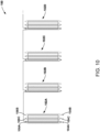
Figure 9 is a schematic diagram of astator segment 102A and astator segment 102B of theelectric propulsion system 100. Thestator segment 102A includes a pair ofteeth teeth teeth 104E and 104F. Theteeth 104E and 104F are immediately adjacent to and between the pair ofteeth teeth - The
stator segment 102A also includes a pair ofcoils teeth coils teeth coils teeth 104E and 104F. - The
stator segment 102B includes the same components as thestator segment 102A, with the first phase winding of thestator segment 102B being wired in series with the first phase winding of thestator segment 102A, the second phase winding of thestator segment 102B being wired in series with the second phase winding of thestator segment 102A, and the third phase winding of thestator segment 102B being wired in series with the third phase winding of thestator segment 102A. The three phase windings are connected together at a neutral terminal. -
Figure 10 is a schematic diagram ofstator segments 102A-D of theelectric propulsion system 100. Thestator segment 102A includes atooth 104A, atooth 104B, and atooth 104C that is immediately adjacent to and between thetooth 104A and thetooth 104B. - The
stator segment 102A also includes acoil 106A (e.g., a first phase winding) wrapped around thetooth 104A, acoil 106B (e.g., a second phase winding) wrapped around thetooth 104B, and acoil 106C (e.g., a third phase winding) wrapped around thetooth 104C. Thecoils 106A-C are electrically connected to each other at a neutral terminal. - The
stator segments 102B-D include the same components as thestator segment 102A, with the first phase winding of thestator segments 102B-D being wired in series with the first phase winding of thestator segment 102A, the second phase winding of thestator segments 102B-D being wired in series with the second phase winding of thestator segment 102A, and the third phase winding of thestator segments 102B-D being wired in series with the third phase winding of thestator segment 102A. The three phase windings are connected together at a neutral terminal. -
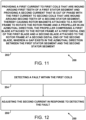
Figure 11 and Figure 12 are block diagrams of amethod 200 and amethod 250 of operating theelectric propulsion system 100. As shown inFigure 11 and Figure 12 , themethod 200 and themethod 250 include one or more operations, functions, or actions as illustrated byblocks - At
block 202, themethod 200 includes providing a first current to first coils that are wound around first teeth of afirst stator segment 102A and providing a second current that is out of phase with the first current to second coils that are wound around second teeth of asecond stator segment 102B, thereby causing therotor magnets 114 attached to therotor frame 112 to rotate therotor frame 112 and thepropeller 116 in theazimuthal direction 110. Functionality related to block 202 is described above with reference toFigs. 3 and4 . - At
block 204, themethod 250 includes detecting a fault within the first coils. - At
block 206, themethod 250 includes adjusting the second current in response to detecting the fault. Functionality related toblocks Figs. 3 and4 . - The description of the different advantageous arrangements has been presented for purposes of illustration and description, and is not intended to be exhaustive or limited to the examples in the form disclosed. Many modifications and variations will be apparent to those of ordinary skill in the art. Further, different advantageous examples may describe different advantages as compared to other advantageous examples. The example or examples selected are chosen and described in order to explain the principles of the examples, the practical application, and to enable others of ordinary skill in the art to understand the disclosure for various examples with various modifications as are suited to the particular use contemplated.
Claims (15)
- An electric propulsion system (100) comprising:a first stator segment (102A) comprising first teeth (104A-I) and first coils (106A-I) wound around the first teeth;a second stator segment (102B) comprising second teeth (104J-R) and second coils (106J-R) wound around the second teeth, wherein a gap (108A) exists in an azimuthal direction (110) between the first stator segment and the second stator segment;a rotor frame (112);rotor magnets (114) attached to the rotor frame and configured to rotate the rotor frame in the azimuthal direction in response to the first coils or the second coils being provided current; anda propeller (116) comprising a first blade (118A) attached to the rotor frame at a first distal end (120A) of the first blade and a second blade (118B) attached to the rotor frame at a second distal end (120B) of the second blade.
- The electric propulsion system of claim 1, wherein the first stator segment and the second stator segment are coplanar.
- The electric propulsion system of claim 1 or 2, wherein:
the rotor magnets are elongated in the azimuthal direction (110) transverse to an axial direction (124) of the electric propulsion system. - The electric propulsion system of any preceding claim, wherein each of the rotor magnets comprise magnet segments (115) that are staggered in the azimuthal direction moving along an axial direction (124) of the electric propulsion system.
- The electric propulsion system of any preceding claim, wherein:a first proximal end (126A) of the first blade is attached to a second proximal end (126B) of the second blade; and/orthe propeller is configured to move air (130) over the first coils and the second coils.
- The electric propulsion system of any preceding claim, wherein the first coils (106A-I) are in series with each other and the second coils (106J-R) are in series with each other, and wherein the first coils are electrically connected to the second coils at a neutral terminal (128).
- The electric propulsion system of any preceding claim, wherein the first teeth comprise:a first pair of teeth (104A-B);a second pair of teeth (104E-F); anda third pair of teeth (104C-D) that is immediately adjacent to and between the first pair of teeth and the second pair of teeth,wherein a first pair of coils (106A-B) of the first coils are wrapped around the first pair of teeth, a second pair of coils (106E-F) of the first coils are wrapped around the second pair of teeth, and a third pair of coils (106C-D) of the first coils are wrapped around the third pair of teeth.
- The electric propulsion system of any preceding claim, wherein the first teeth comprise:a first tooth (104A);a second tooth (104C); anda third tooth (104B) that is immediately adjacent to and between the first tooth and the second tooth,wherein the first coils comprise a first coil (106A) wrapped around the first tooth, a second coil (106C) wrapped around the second tooth, and a third coil (106B) wrapped around the third tooth, and wherein the first coil, the second coil, and the third coil are electrically connected to each other at a neutral terminal (128).
- The electric propulsion system of any preceding claim, wherein:the rotor frame is distal with respect to the first stator segment and the second stator segment and, optionally, the propeller is axially offset with respect to the rotor frame; orthe rotor frame is proximal with respect to the first stator segment and the second stator segment.
- An aircraft (10) comprising:a body (12); andthe electric propulsion system (100) of any preceding claim configured to propel the body.
- A method (200) of operating an electric propulsion system (100), the method comprising:
(202) providing a first current to first coils (106A-C) that are wound around first teeth (104A-C) of a first stator segment (102A) and providing a second current that is out of phase with the first current to second coils (106M-O) that are wound around second teeth (104M-O) of a second stator segment (102B), thereby causing rotor magnets (114) attached to a rotor frame (112) to rotate the rotor frame and a propeller (116) in an azimuthal direction (110), the propeller comprising a first blade (118A) attached to the rotor frame at a first distal end (120A) of the first blade and a second blade (118B) attached to the rotor frame at a second distal end (120B) of the second blade, wherein a gap (108) exists in the azimuthal direction between the first stator segment and the second stator segment. - The method of claim 11, further comprising:detecting (204) a fault within the first coils;adjusting (206) the second current in response to detecting the fault; and, optionally,wherein detecting the fault comprises detecting an open circuit within the first coils, and wherein adjusting the second current comprises increasing the second current.
- The method of claim 11 or 12, wherein the rotor magnets are elongated in azimuthal direction (110) transverse to an axial direction (124) of the electric propulsion system, and wherein causing the rotor magnets to rotate the rotor frame comprises:causing first portions (115) of the rotor magnets (114) to pass the first stator segment; andthereafter causing second portions (119) of the rotor magnets that are at different axial positions than the first portions to pass the first stator segment.
- The method of any of claims 11 to 13, wherein each of the rotor magnets comprise magnet segments that are staggered in the azimuthal direction moving along an axial direction (124) of the electric propulsion system, and wherein causing the rotor magnets to rotate the rotor frame comprises:causing first magnet segments (117A) of the rotor magnets to pass the first stator segment;
andthereafter causing second magnet segments (117B) of the rotor magnets that are at different axial positions than the first magnet segments to pass the first stator segment. - The method of any of claims 11 to 14, wherein causing the rotor magnets to rotate the propeller comprises moving air (130) over the first coils and the second coils.
Applications Claiming Priority (1)
| Application Number | Priority Date | Filing Date | Title |
|---|---|---|---|
| US18/190,782 US20240333049A1 (en) | 2023-03-27 | 2023-03-27 | Electric propulsion system |
Publications (1)
| Publication Number | Publication Date |
|---|---|
| EP4438498A1 true EP4438498A1 (en) | 2024-10-02 |
Family
ID=89715815
Family Applications (1)
| Application Number | Title | Priority Date | Filing Date |
|---|---|---|---|
| EP24153739.8A Pending EP4438498A1 (en) | 2023-03-27 | 2024-01-24 | Electric propulsion system |
Country Status (3)
| Country | Link |
|---|---|
| US (1) | US20240333049A1 (en) |
| EP (1) | EP4438498A1 (en) |
| CN (1) | CN118701292A (en) |
Families Citing this family (1)
| Publication number | Priority date | Publication date | Assignee | Title |
|---|---|---|---|---|
| US12420924B2 (en) * | 2022-08-10 | 2025-09-23 | Regent Craft, Inc. | Hydrofoil takeoff and landing with multiple hydrofoils |
Citations (6)
| Publication number | Priority date | Publication date | Assignee | Title |
|---|---|---|---|---|
| EP1647081A1 (en) * | 2003-07-11 | 2006-04-19 | Arcelik Anonim Sirketi | Motor with modular stator segments |
| US20120098382A1 (en) * | 2010-10-21 | 2012-04-26 | James Ching Sik Lau | Electric motor |
| US20180219434A1 (en) * | 2017-01-31 | 2018-08-02 | Regal Beloit Australia, PTY., Ltd. | Composite stator for axial flux electric machines and methods of assembling the same |
| US20180287459A1 (en) * | 2017-03-29 | 2018-10-04 | SZ DJI Technology Co., Ltd. | Hollow motor apparatuses and associated systems and methods |
| EP3968503A1 (en) * | 2020-08-31 | 2022-03-16 | General Electric Company | Turbomachine equipped with an embedded electric machine having a segmented and movable stator |
| EP4037167A1 (en) * | 2021-02-02 | 2022-08-03 | The Boeing Company | Rotary electric machine |
Family Cites Families (11)
| Publication number | Priority date | Publication date | Assignee | Title |
|---|---|---|---|---|
| US4642502A (en) * | 1986-04-24 | 1987-02-10 | General Motors Corporation | Dynamoelectric machine with permanent magnet and magnet mounting surface arrangement |
| KR100382226B1 (en) * | 2001-03-30 | 2003-05-09 | 학교법인 한양학원 | Brushless direct current motor including assistant winding at stator winding |
| JP5123008B2 (en) * | 2008-03-05 | 2013-01-16 | 株式会社ミツバ | Brushless motor |
| DE102012205191A1 (en) * | 2012-03-30 | 2013-10-02 | Bayerische Motoren Werke Aktiengesellschaft | Vibration prevention in synchronous machines |
| EP2654181B1 (en) * | 2012-04-20 | 2016-03-23 | Siemens Aktiengesellschaft | Rotor arrangement and electromechanical transducer having non-parallel permanent magnets |
| US8922087B1 (en) * | 2013-08-26 | 2014-12-30 | Norman P Rittenhouse | High efficiency low torque ripple multi-phase permanent magnet machine |
| DE102014019217A1 (en) * | 2014-12-19 | 2016-06-23 | Daimler Ag | Method of punching a laminated core |
| US20170104385A1 (en) * | 2015-10-08 | 2017-04-13 | Adam C. Salamon | Reduced Complexity Ring Motor Design for Propeller Driven Vehicles |
| CN105871267A (en) * | 2016-05-23 | 2016-08-17 | 南京航空航天大学 | Four-phase double-channel fault-tolerant transverse flux motor drive system |
| US11539322B1 (en) * | 2021-06-15 | 2022-12-27 | Hamilton Sundstrand Corporation | Fault tolerant motor including redundant wye winding and dual-state neutral leads |
| US11804759B1 (en) * | 2022-10-15 | 2023-10-31 | Beta Air, Llc | Motor with a fully welded rotor for an electric aircraft and a method for manufacturing |
-
2023
- 2023-03-27 US US18/190,782 patent/US20240333049A1/en active Pending
-
2024
- 2024-01-24 EP EP24153739.8A patent/EP4438498A1/en active Pending
- 2024-03-26 CN CN202410353404.2A patent/CN118701292A/en active Pending
Patent Citations (6)
| Publication number | Priority date | Publication date | Assignee | Title |
|---|---|---|---|---|
| EP1647081A1 (en) * | 2003-07-11 | 2006-04-19 | Arcelik Anonim Sirketi | Motor with modular stator segments |
| US20120098382A1 (en) * | 2010-10-21 | 2012-04-26 | James Ching Sik Lau | Electric motor |
| US20180219434A1 (en) * | 2017-01-31 | 2018-08-02 | Regal Beloit Australia, PTY., Ltd. | Composite stator for axial flux electric machines and methods of assembling the same |
| US20180287459A1 (en) * | 2017-03-29 | 2018-10-04 | SZ DJI Technology Co., Ltd. | Hollow motor apparatuses and associated systems and methods |
| EP3968503A1 (en) * | 2020-08-31 | 2022-03-16 | General Electric Company | Turbomachine equipped with an embedded electric machine having a segmented and movable stator |
| EP4037167A1 (en) * | 2021-02-02 | 2022-08-03 | The Boeing Company | Rotary electric machine |
Also Published As
| Publication number | Publication date |
|---|---|
| US20240333049A1 (en) | 2024-10-03 |
| CN118701292A (en) | 2024-09-27 |
Similar Documents
| Publication | Publication Date | Title |
|---|---|---|
| US11456637B2 (en) | Motor with rotor holder having first and second magnets with different intervals to holder | |
| CN111509948B (en) | Multi-degree-of-freedom magnetic field modulation type magnetic screw actuator and integrated design method thereof | |
| US5866965A (en) | Variable reluctance motor having foil wire wound coils | |
| US20130169074A1 (en) | Synchronous relcutance motor for conducting media | |
| EP3378145B1 (en) | Electric generator with a rotational resistance avoidance feature | |
| SG189798A1 (en) | High-speed permanent magnet motor and generator with low-loss metal rotor | |
| CN112072809B (en) | Permanent magnet rotating armature motor capable of adjusting magnetic field in mechanical mode | |
| WO2015018083A1 (en) | Birotor motor as well as fan and compressor using same | |
| CN118701292A (en) | Electric propulsion system and method of operating the same, and aircraft | |
| WO2009093043A2 (en) | Rotary electromagnetic machines | |
| JPWO2016063324A1 (en) | Rotation angle detection device, rotating electric machine, and elevator hoisting machine | |
| WO2020028362A1 (en) | Brushless direct current motor with dual stators | |
| US20190081541A1 (en) | Hollow Single-Phase Induction Motor | |
| US9633762B2 (en) | Cable | |
| EP2822148B1 (en) | Rotor for induction torque motor and induction torque motor | |
| CN104989727B (en) | Combined-type five-degree-of-freedom electromagnetic bearing | |
| US2402214A (en) | Electric motor | |
| US20160285346A1 (en) | Cooling device for motor | |
| EP2852963B1 (en) | X-ray tube rotor with carbon composite based material | |
| JP7229526B2 (en) | Embedded magnet type motor, position estimation device and position estimation method | |
| CN205847036U (en) | A kind of drag cup brushless electric machine | |
| US20250373135A1 (en) | Homopolar vector rotation motor | |
| CN106921273B (en) | Permanent magnet direct current motor with commutation-free structure | |
| CN107306074A (en) | A kind of drag cup brushless electric machine | |
| EP2845293B1 (en) | Internally cooled servo motor with a segmented stator |
Legal Events
| Date | Code | Title | Description |
|---|---|---|---|
| PUAI | Public reference made under article 153(3) epc to a published international application that has entered the european phase |
Free format text: ORIGINAL CODE: 0009012 |
|
| STAA | Information on the status of an ep patent application or granted ep patent |
Free format text: STATUS: THE APPLICATION HAS BEEN PUBLISHED |
|
| AK | Designated contracting states |
Kind code of ref document: A1 Designated state(s): AL AT BE BG CH CY CZ DE DK EE ES FI FR GB GR HR HU IE IS IT LI LT LU LV MC ME MK MT NL NO PL PT RO RS SE SI SK SM TR |
|
| STAA | Information on the status of an ep patent application or granted ep patent |
Free format text: STATUS: REQUEST FOR EXAMINATION WAS MADE |
|
| 17P | Request for examination filed |
Effective date: 20250219 |