EP4438487A1 - Aéronef comportant une canalisation de transport de dihydrogène, un canal d'enfouissement de ladite canalisation de transport et un système d'évacuation de l air et de l eau présente dans ledit canal d'enfouissement - Google Patents
Aéronef comportant une canalisation de transport de dihydrogène, un canal d'enfouissement de ladite canalisation de transport et un système d'évacuation de l air et de l eau présente dans ledit canal d'enfouissement Download PDFInfo
- Publication number
- EP4438487A1 EP4438487A1 EP24159662.6A EP24159662A EP4438487A1 EP 4438487 A1 EP4438487 A1 EP 4438487A1 EP 24159662 A EP24159662 A EP 24159662A EP 4438487 A1 EP4438487 A1 EP 4438487A1
- Authority
- EP
- European Patent Office
- Prior art keywords
- aircraft
- pipe
- channel
- transport
- distal end
- Prior art date
- Legal status (The legal status is an assumption and is not a legal conclusion. Google has not performed a legal analysis and makes no representation as to the accuracy of the status listed.)
- Granted
Links
Images


Classifications
-
- B—PERFORMING OPERATIONS; TRANSPORTING
- B64—AIRCRAFT; AVIATION; COSMONAUTICS
- B64D—EQUIPMENT FOR FITTING IN OR TO AIRCRAFT; FLIGHT SUITS; PARACHUTES; ARRANGEMENT OR MOUNTING OF POWER PLANTS OR PROPULSION TRANSMISSIONS IN AIRCRAFT
- B64D29/00—Power-plant nacelles, fairings or cowlings
- B64D29/02—Power-plant nacelles, fairings or cowlings associated with wings
-
- B—PERFORMING OPERATIONS; TRANSPORTING
- B64—AIRCRAFT; AVIATION; COSMONAUTICS
- B64D—EQUIPMENT FOR FITTING IN OR TO AIRCRAFT; FLIGHT SUITS; PARACHUTES; ARRANGEMENT OR MOUNTING OF POWER PLANTS OR PROPULSION TRANSMISSIONS IN AIRCRAFT
- B64D37/00—Arrangements in connection with fuel supply for power plant
- B64D37/005—Accessories not provided for in the groups B64D37/02 - B64D37/28
-
- B—PERFORMING OPERATIONS; TRANSPORTING
- B64—AIRCRAFT; AVIATION; COSMONAUTICS
- B64D—EQUIPMENT FOR FITTING IN OR TO AIRCRAFT; FLIGHT SUITS; PARACHUTES; ARRANGEMENT OR MOUNTING OF POWER PLANTS OR PROPULSION TRANSMISSIONS IN AIRCRAFT
- B64D27/00—Arrangement or mounting of power plants in aircraft; Aircraft characterised by the type or position of power plants
- B64D27/02—Aircraft characterised by the type or position of power plants
- B64D27/30—Aircraft characterised by electric power plants
- B64D27/35—Arrangements for on-board electric energy production, distribution, recovery or storage
- B64D27/355—Arrangements for on-board electric energy production, distribution, recovery or storage using fuel cells
-
- B—PERFORMING OPERATIONS; TRANSPORTING
- B64—AIRCRAFT; AVIATION; COSMONAUTICS
- B64D—EQUIPMENT FOR FITTING IN OR TO AIRCRAFT; FLIGHT SUITS; PARACHUTES; ARRANGEMENT OR MOUNTING OF POWER PLANTS OR PROPULSION TRANSMISSIONS IN AIRCRAFT
- B64D37/00—Arrangements in connection with fuel supply for power plant
- B64D37/02—Tanks
- B64D37/14—Filling or emptying
- B64D37/20—Emptying systems
-
- B—PERFORMING OPERATIONS; TRANSPORTING
- B64—AIRCRAFT; AVIATION; COSMONAUTICS
- B64D—EQUIPMENT FOR FITTING IN OR TO AIRCRAFT; FLIGHT SUITS; PARACHUTES; ARRANGEMENT OR MOUNTING OF POWER PLANTS OR PROPULSION TRANSMISSIONS IN AIRCRAFT
- B64D37/00—Arrangements in connection with fuel supply for power plant
- B64D37/30—Fuel systems for specific fuels
-
- B—PERFORMING OPERATIONS; TRANSPORTING
- B64—AIRCRAFT; AVIATION; COSMONAUTICS
- B64D—EQUIPMENT FOR FITTING IN OR TO AIRCRAFT; FLIGHT SUITS; PARACHUTES; ARRANGEMENT OR MOUNTING OF POWER PLANTS OR PROPULSION TRANSMISSIONS IN AIRCRAFT
- B64D37/00—Arrangements in connection with fuel supply for power plant
- B64D37/32—Safety measures not otherwise provided for, e.g. preventing explosive conditions
-
- B—PERFORMING OPERATIONS; TRANSPORTING
- B64—AIRCRAFT; AVIATION; COSMONAUTICS
- B64D—EQUIPMENT FOR FITTING IN OR TO AIRCRAFT; FLIGHT SUITS; PARACHUTES; ARRANGEMENT OR MOUNTING OF POWER PLANTS OR PROPULSION TRANSMISSIONS IN AIRCRAFT
- B64D27/00—Arrangement or mounting of power plants in aircraft; Aircraft characterised by the type or position of power plants
- B64D27/02—Aircraft characterised by the type or position of power plants
- B64D27/10—Aircraft characterised by the type or position of power plants of gas-turbine type
- B64D27/12—Aircraft characterised by the type or position of power plants of gas-turbine type within, or attached to, wings
Definitions
- the present invention relates to the field of aircraft and, in particular, to aircraft whose energy source is liquid or gaseous dihydrogen, whether to power a fuel cell or directly the combustion chamber of an engine.
- the present invention thus relates to an aircraft comprising a dihydrogen transport pipe, a burial channel which allows the passage of the transport pipe and a system for evacuating the water and air present in the burial channel.
- dihydrogen As an energy source in an aircraft.
- the dihydrogen is stored in a tank and a transport pipeline ensures the transport of the dihydrogen from the tank to the consuming device, such as a fuel cell or the combustion chamber of an engine.
- a burial channel can be used for each transport pipeline, in which the transport pipeline is housed and fixed.
- An object of the present invention is to provide an aircraft comprising a dihydrogen transport pipe, a burial channel which allows the passage of the transport pipe and a system for evacuating air and water and dihydrogen in the event of a leak.
- the evacuation system comprises a first pipe with a proximal end, a distal end and an elbow between said proximal end and said distal end, the elbow constitutes a low point for the first pipe, and the first pipe is fluidically connected to the second end of the gutter by said proximal end and opens to the outside at an exterior wall of the aircraft by said distal end.
- the evacuation system comprises a second pipe with a proximal end and a distal end, the second pipe is fluidically connected to the elbow by said proximal end and opens outside the aircraft at an exterior wall of the aircraft by said distal end, and between the proximal end of the second pipe and the distal end of the second pipe, the second pipe has a downward slope.
- the aircraft comprises a wing and the distal end of the first pipe opens onto the upper surface of the wing.
- the exhaust system comprises a cover which extends outside the aircraft around the distal end, having a closed face facing the front of the aircraft and an open face facing the rear of the aircraft.
- the evacuation system comprises a heating element arranged near said second pipe.
- the distal end of the second pipe is oriented towards the rear of the aircraft.
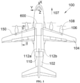
- FIG. 1 shows an aircraft 100 which has a fuselage 102 on either side of which a wing 104 is fixed. Under each wing 104 is fixed at least one propulsion system 106.
- X is called the longitudinal direction of the aircraft 100
- Y the transverse direction of the aircraft 100 which is horizontal when the aircraft is on the ground
- Z the vertical direction or vertical height when the aircraft is on the ground
- front and rear are to be considered in relation to a direction of advancement of the aircraft 100 during operation of the propulsion systems 106, this direction being represented schematically by the arrow 107.
- each propulsion system 106 comprises an electric motor, a propeller 108 mounted on the drive shaft of said electric motor and a fuel cell which supplies the motor with electricity.
- the fuel cell is supplied with oxygen and dihydrogen to produce electricity.
- the propulsion system 106 may take the form of a turbojet engine whose fuel that is burned in the combustion chamber is dihydrogen.
- the aircraft 100 also comprises a dihydrogen tank 110 which is here disposed in a rear portion of the fuselage, but which could be disposed in another portion of the aircraft 100.
- the dihydrogen may be liquid or gaseous.
- the aircraft 100 comprises at least one transport pipe 112a-b in which the dihydrogen flows, between, upstream the tank 110 and downstream the consumer device 106 which consumes the dihydrogen and which can here be the fuel cell or the turbojet.
- the transport pipes 112a-b are preferably arranged in the upper part of the aircraft 100 and thus extend along the fuselage 102 and the wings 104 in the upper part thereof.
- a transport pipeline 112a which extends and ensures the transport of dihydrogen between the tank 110 and a consumer device 106 on the port side and there is a transport pipeline 112b which extends and ensures the transport of dihydrogen between the tank 110 and a consumer device 106 on the starboard side.
- FIG. 2 shows a section of the wing 104 on the port side with the transport pipe 112a, but the invention applies in the same way to the starboard side.
- the aircraft 100 comprises for each transport pipe 112a, a burial channel 200 comprising a gutter 202 in which the transport pipe 112a is housed and fixed.
- FIG. 3 shows the burial channel 200 with the gutter 202 which, in the embodiment of the invention presented in the Figs. 2 and 3 , comprises a bottom 203, an opening opposite the bottom 203, and a cover 204 which covers the opening of the channel 202 by closing it at least in part.
- the transport pipe 112a-b is thus housed between the bottom 203 and the opening and here the cover 204.
- the transport pipe 112a-b is fixed to the channel 202 by any suitable means such as for example clamps.
- the channel 202 has a trapezoidal section, but sections of different shapes are possible.
- the cover 204 here constitutes an external wall of the aircraft 100, that is to say that it is in direct contact with the external air surrounding the aircraft 100.
- the cover 204 is fixed to the external wall of the aircraft 100 by any suitable fixing means, such as for example here bolts 210.
- the cover 204 is pierced with ventilation windows 206 which allow the passage of dihydrogen, in particular in the event of a leak from the transport pipe 112a-b, towards the outside, thereby limiting the concentration of dihydrogen in the burial channel 200 and the risks linked to the presence of dihydrogen.
- the cover 204 is in an upper position relative to the bottom 203, that is to say above.
- each ventilation window 206 is closed by a plug 208 made of a breathable material for dihydrogen, that is to say that the plug 208 is impermeable to external water which cannot penetrate into the burial channel 200a-b, and permeable, among other things for dihydrogen which is present in the burial channel 200a-b and can be evacuated to the outside.
- the plug 208 is made for example of polypropylene or polyethylene.
- each plug 208 is made of a material capable of breaking under the effect of heat, such as for example polypropylene or polyethylene.
- the plug 208 constitutes a fuse which makes it possible to open the ventilation window 206 if necessary to blow out the flames.
- the material for the plug 208 is chosen so as to break when the temperature inside the channel 202 reaches a value lower than the maximum temperature acceptable by the channel 202 and the transport pipeline 112a-b installed in the channel 202, i.e. the temperature from which the integrity of the channel 202 and the transport pipeline 112a-b is no longer guaranteed.
- the cover 204 breaks under the effect of the overpressure, thus limiting the risks of breakage of the channel 202.
- the tear resistance of the cover 204 is lower than the tear resistance of the channel 202, for example by producing thinner zones. It is also possible to provide that the breakage occurs at the level of the means for fixing the cover 204, for example by using fusible bolts which break beyond a certain pressure.
- the aircraft 100 comprises a ventilation system 600 which is arranged here at the level of the upper part of the aircraft 100 at the level of the junction of the wings 104 and which allows the introduction of outside air and the sending of this air into each burial channel 200.
- a ventilation system 600 which is arranged here at the level of the upper part of the aircraft 100 at the level of the junction of the wings 104 and which allows the introduction of outside air and the sending of this air into each burial channel 200.
- the channel 202 here comprises an intermediate floor 520 between the bottom 203 and the opening.
- the intermediate floor 520 is at a distance from the bottom 203 and separates the channel 202 into an upper channel 521 in which the transport pipe 112a-b is secured and a lower channel 523 in which the air from the ventilation system 600 circulates.
- the upper channel 521 extends between the intermediate floor 520 and the cover 204
- the lower gutter 523 extends between the bottom 203 and the intermediate floor 520.
- the intermediate floor 520 is perforated and is here pierced with holes 522 which provide ventilation for the upper gutter 521.
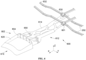
- FIG. 4 shows an example of the ventilation system 600 with the channels 202 but without the transport pipes 112a-b which are housed in said channels 202.
- the ventilation system 600 comprises an air vent 610 arranged to capture air from outside the aircraft 100 and at least one supply line 614 fluidically connected to the air vent 610.
- each supply pipe 614 channels the air taken from outside at the level of the air vent 610 towards one or more lower channels 523 of the channels 202.
- the air vent 610 can alternately take a closed position and an open position thanks to a hatch 620 which is mounted to move between a closed position in which it isolates each window 604 from the outside air and an open position in which it retracts to allow free passage of outside air to each window 604.
- the movement of the hatch 620 is ensured by any movement system known to those skilled in the art such as for example a motor or a hydraulic cylinder.
- the air vent 610 comprises an air inlet 602 at which each supply pipe 614 opens through a window 604 open towards the front of the aircraft 100 in order to capture outside air when the aircraft 100 is moving forward or is stationary.
- the aircraft 100 At an intersection between a supply pipe 614 and one or more lower channels 523, to ensure the distribution of air to the or each lower channel 523, the aircraft 100 here comprises a junction box 601 which ensures the fluid connection between the supply pipe 614 and the or each lower channel 523.
- an air flow entering the junction box 601 will diffuse at the level of the or each lower channel 523
- fans 650 are located in one or more of the supply lines 614.
- Each burial channel 200 thus comprises a first end 630 through which the transport pipe 112a-b coming from upstream enters the gutter 202 and a second end 632 through which the transport pipe 112a-b going downstream exits the gutter 202.
- the first end 630 is therefore the closest to the reservoir 110 and the second end 632 is the closest to the consumer device 106.
- the aircraft 100 For each second end 632, the aircraft 100 comprises an evacuation system 150 fluidically connected between the second end of the channel 202, and more particularly here the lower channel 523 of said channel 202, and the exterior of the aircraft 100.
- the evacuation system 150 which is schematically represented in the Fig. 1 is intended to ensure the evacuation of air and water which are present in the gutter 202, and more particularly here in the lower gutter 523 of said gutter 202 and more generally the gases and liquids present in the gutter 202.
- the evacuation system 150 is intended to evacuate only part of the air present in the gutter 202. This evacuation system 150 is intended to maximize the flow of air between the first and second ends 630, 632 of the burial channel 200, in order to dilute as much as possible any leaks of dihydrogen.
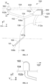
- FIG. 5 shows an example of the embodiment of the evacuation system 150 and the Figs. 6 And 7 show sections of said evacuation system 150.
- the evacuation system 150 is arranged here at the level of the wing 104 in the vicinity of the consumer device 106, here the propulsion system 106 which is supplied by the transport pipe 112a.
- the evacuation system 150 comprises a first pipe 152 which has a proximal end 152a, a distal end 152b and an elbow 154 between the proximal end 152a and the distal end 152b, where the elbow 154 constitutes a low point for the first pipe 152, that is to say that between the proximal end 152a and the elbow 154, on the one hand, and between the distal end 152b and the elbow 154, on the other hand, the first pipe 152 has downward slopes.
- the first pipe 152 is fluidically connected to the second end 632 of the channel 202, here of the lower channel 523 of said channel 202, by its proximal end 152a and opens to the outside of the aircraft 100 at an outer wall of the aircraft 100, here of the wing 104, by its distal end 152b.
- An outer wall of the aircraft 100 is in direct contact with the outside air surrounding the aircraft 100.
- the distal end 152b of the first pipe 152 opens onto the upper surface of the wing 104 of the aircraft 100.
- a depression is created at the upper surface of the wing 104, and as the first pipe 152 is fluidically connected by its distal end 152b, to the upper surface of the wing 104, there is a suction of the outside air surrounding the aircraft 100 into the first duct 152, which maximizes the air flow in said first duct 152.
- the first pipe 152 ensures the evacuation of air and dihydrogen in the event of a leak from the transport pipe 112a into the gutter 202 by ensuring evacuation over the entire length of said gutter 202.
- the first part of the first pipe 152, between its proximal end 152a and the elbow 154, also ensures the evacuation of water from the gutter 202.
- the elbow 154 corresponds to a low point of the first pipe 152; it is at the elbow 154 that the water separates, by gravity, from the air and dihydrogen.
- the evacuation system 150 comprises a second pipe 156 which has a proximal end 156a and a distal end 156b, where the second pipe 156 is fluidically connected to the elbow 154 by its proximal end 156a and opens outside the aircraft 100 at an exterior wall of the aircraft 100, here of the consumer device 106, by its distal end 156b.
- the second pipe 156 has a downward slope to ensure the flow of water or any other liquid towards the outside and thus ensuring drainage over the entire length of said channel 202.
- the evacuation system 150 comprises a cover 160 which extends outside the aircraft 100 around the distal end 152b by having a closed face oriented towards the front of the aircraft 100 and an open face oriented towards the rear of the aircraft 100.
- the gases present in the first pipe 152 are then sucked in by the outside air due to the speed of movement of the aircraft 100.
- the cover 160 is fixed to the external wall of the aircraft 100.
- the evacuation system 150 comprises a heating element 162, for example an electrically powered electrical resistor, which is arranged near said second pipe 156.
- heating element 162 is arranged in a fin 164 in which the second pipe 156 is enclosed.
- the distal end 156b of the second pipe 156 is oriented towards the rear of the aircraft 100.
Landscapes
- Engineering & Computer Science (AREA)
- Aviation & Aerospace Engineering (AREA)
- Traffic Control Systems (AREA)
- Rigid Pipes And Flexible Pipes (AREA)
- Filling Or Discharging Of Gas Storage Vessels (AREA)
- Jet Pumps And Other Pumps (AREA)
Abstract
Description
- La présente invention se rapporte au domaine des aéronefs et, en particulier, des aéronefs dont la source d'énergie est du dihydrogène liquide ou gazeux que ce soit pour alimenter une pile à combustible ou directement la chambre de combustion d'un moteur. La présente invention concerne ainsi un aéronef comportant une canalisation de transport de dihydrogène, un canal d'enfouissement qui permet le passage de la canalisation de transport et un système d'évacuation de l'eau et de l'air présents dans le canal d'enfouissement.
- Il est connu d'utiliser le dihydrogène comme source d'énergie dans un aéronef. Le dihydrogène est stocké dans un réservoir et une canalisation de transport assure le transport du dihydrogène du réservoir vers le dispositif consommateur, comme par exemple une pile à combustible ou la chambre de combustion d'un moteur.
- Pour sécuriser le transport du dihydrogène, il peut être utilisé pour chaque canalisation de transport, un canal d'enfouissement dans lequel la canalisation de transport est logée et fixée.
- Dans ce type d'installation, de l'eau peut être stagnée dans le canal d'enfouissement et il peut arriver que du dihydrogène s'échappe d'une canalisation de transport.
- Il est donc souhaitable de prévoir une installation qui assure l'évacuation de l'eau et de l'air ou du dihydrogène présents dans le canal d'enfouissement vers l'extérieur.
- Un objet de la présente invention est de proposer un aéronef comportant une canalisation de transport de dihydrogène, un canal d'enfouissement qui permet le passage de la canalisation de transport et un système d'évacuation d'air et d'eau et de dihydrogène en cas de fuite.
- À cet effet, est proposé un aéronef comportant :
- au moins une canalisation de transport dans laquelle s'écoule du dihydrogène, entre, en amont un réservoir et en aval un dispositif consommateur,
- pour chaque canalisation de transport, un canal d'enfouissement comportant un caniveau dans lequel est fixée la canalisation de transport et présentant une première extrémité par laquelle la canalisation de transport provenant de l'amont pénètre dans le caniveau et une deuxième extrémité par laquelle la canalisation de transport allant vers l'aval sort du caniveau, et
- pour chaque deuxième extrémité, un système d'évacuation fluidiquement connecté entre la deuxième extrémité du caniveau et l'extérieur de l'aéronef et destiné à assurer l'évacuation de l'air et de l'eau.
- Selon l'invention, le système d'évacuation comporte une première canalisation avec une extrémité proximale, une extrémité distale et un coude entre ladite extrémité proximale et ladite extrémité distale, le coude constitue un point bas pour la première canalisation, et la première canalisation est fluidiquement connectée à la deuxième extrémité du caniveau par ladite extrémité proximale et débouche à l'extérieur au niveau d'une paroi extérieure de l'aéronef par ladite extrémité distale.
- Selon l'invention, le système d'évacuation comporte une deuxième canalisation avec une extrémité proximale et une extrémité distale, la deuxième canalisation est fluidiquement connectée au coude par ladite extrémité proximale et débouche à l'extérieur de l'aéronef au niveau d'une paroi extérieure de l'aéronef par ladite extrémité distale, et entre l'extrémité proximale de la deuxième canalisation et l'extrémité distale de la deuxième canalisation, la deuxième canalisation présente une pente descendante.
- Avec un tel arrangement, l'eau et l'air présents dans la canalisation de transport sont aspirés sur toute la longueur de ladite canalisation de transport. En effet, avec un tel arrangement, la circulation d'air dans la canalisation de transport est forcée, grâce à une pressurisation au niveau de la première extrémité de la canalisation de transport de manière à forcer l'air à circuler dans la canalisation de transport, et à l'aspiration résultante de l'air dans la canalisation de transport jusqu'à la deuxième extrémité de la canalisation de transport (créant une dépression). Ceci permet de maximiser une dilution de dihydrogène dans l'air en cas de fuite de dihydrogène.
- Avantageusement, l'aéronef comporte une aile et l'extrémité distale de la première canalisation débouche sur l'extrados de l'aile.
- Avantageusement, le système d'évacuation comporte un capot qui s'étend à l'extérieur de l'aéronef autour de l'extrémité distale en présentant une face fermée orientée vers l'avant de l'aéronef et une face ouverte orientée vers l'arrière de l'aéronef.
- Avantageusement, le système d'évacuation comporte un élément chauffant disposé près de ladite deuxième canalisation.
- Avantageusement, l'extrémité distale de la deuxième canalisation est orientée vers l'arrière de l'aéronef.
- Les caractéristiques de l'invention mentionnées ci-dessus, ainsi que d'autres, apparaîtront plus clairement à la lecture de la description suivante d'un exemple de réalisation, ladite description étant faite en relation avec les dessins joints, parmi lesquels :
-
Fig. 1 est une vue de dessus d'un aéronef selon l'invention, -
Fig. 2 est une vue en coupe d'une aile de l'aéronef de laFig. 1 selon la ligne II-II, -
Fig. 3 est une vue en perspective d'un canal d'enfouissement selon l'invention, -
Fig. 4 est une vue en perspective d'un exemple de canaux d'enfouissement et d'un système d'aération pouvant être mis en oeuvre dans l'invention, -
Fig. 5 est une vue en perspective d'un système d'évacuation d'air et d'eau selon l'invention, -
Fig. 6 est une vue en coupe selon la ligne VI-VI du système d'évacuation de laFig. 5 , et -
Fig. 7 est une vue en coupe selon la ligne VII-VII du système d'évacuation de laFig. 5 . - La
Fig. 1 montre un aéronef 100 qui présente un fuselage 102 de part et d'autre duquel est fixée une aile 104. Sous chaque aile 104 est fixé au moins un système de propulsion 106. - Par convention, on appelle X la direction longitudinale de l'aéronef 100, Y la direction transversale de l'aéronef 100 qui est horizontale lorsque l'aéronef est au sol, et Z la direction verticale ou hauteur verticale lorsque l'aéronef est au sol, ces trois directions X, Y et Z étant orthogonales entre elles.
- D'autre part, les termes " avant " et " arrière " sont à considérer par rapport à une direction d'avancement de l'aéronef 100 lors du fonctionnement des systèmes de propulsion 106, cette direction étant représentée schématiquement par la flèche 107.
- Dans le mode de réalisation de l'invention présenté ici, chaque système de propulsion 106 comprend un moteur électrique, une hélice 108 montée sur l'arbre moteur dudit moteur électrique et une pile à combustible qui alimente le moteur en électricité.
- La pile à combustible est alimentée en oxygène et en dihydrogène afin de produire de l'électricité.
- Dans un autre mode de réalisation, le système de propulsion 106 peut prendre la forme d'un turboréacteur dont le carburant qui est brûlé dans la chambre de combustion est du dihydrogène. L'aéronef 100 comporte également un réservoir de dihydrogène 110 qui est disposé ici dans une partie arrière du fuselage, mais qui pourrait être disposé dans une autre partie de l'aéronef 100. Le dihydrogène peut être liquide ou gazeux.
- Pour transporter le dihydrogène, l'aéronef 100 comporte au moins une canalisation de transport 112a-b dans laquelle s'écoule le dihydrogène, entre, en amont le réservoir 110 et en aval le dispositif consommateur 106 qui consomme le dihydrogène et qui peut être ici la pile à combustible ou le turboréacteur.
- Pour des raisons de facilité de mise en oeuvre, les canalisations de transport 112a-b sont préférentiellement disposées en partie haute de l'aéronef 100 et s'étendent ainsi le long du fuselage 102 et des ailes 104 en partie haute de ceux-ci.
- Dans le mode de réalisation de l'invention présenté à la
Fig. 1 , il y a une canalisation de transport 112a qui s'étend et assure le transport du dihydrogène entre le réservoir 110 et un dispositif consommateur 106 à bâbord et il y a une canalisation de transport 112b qui s'étend et assure le transport du dihydrogène entre le réservoir 110 et un dispositif consommateur 106 à tribord. - La
Fig. 2 montre une coupe de l'aile 104 à bâbord avec la canalisation de transport 112a, mais l'invention s'applique de la même manière à tribord. - Dans le mode de réalisation représenté sur la
Fig. 2 , l'aéronef 100 comporte pour chaque canalisation de transport 112a, un canal d'enfouissement 200 comportant un caniveau 202 dans lequel est logée et fixée la canalisation de transport 112a. - La
Fig. 3 montre le canal d'enfouissement 200 avec le caniveau 202 qui, dans le mode de réalisation de l'invention présenté sur lesFigs. 2 et 3 , comporte un fond 203, une ouverture à l'opposé du fond 203, et un couvercle 204 qui recouvre l'ouverture du caniveau 202 en l'obturant au moins en partie. La canalisation de transport 112a-b est ainsi logée entre le fond 203 et l'ouverture et ici le couvercle 204. La canalisation de transport 112a-b est fixée au caniveau 202 par tous moyens appropriés comme par exemple des colliers. - Dans le mode de réalisation de l'invention présenté sur les
Figs. 2 et 3 , le caniveau 202 présente une section trapézoïdale, mais des sections de forme différente sont possibles. - Le couvercle 204 constitue ici une paroi extérieure de l'aéronef 100, c'est-à-dire qu'elle est en contact direct avec l'air extérieur entourant l'aéronef 100. Le couvercle 204 est fixé à la paroi extérieure de l'aéronef 100 par tous moyens de fixation appropriés, comme par exemple ici des boulons 210.
- Dans le mode de réalisation de l'invention présenté ici, le couvercle 204 est percé de fenêtres de ventilation 206 qui permettent le passage du dihydrogène, en particulier en cas de fuite de la canalisation de transport 112a-b, vers l'extérieur, limitant d'autant la concentration de dihydrogène dans le canal d'enfouissement 200 et les risques liés à la présence de dihydrogène.
- Préférentiellement, le couvercle 204 est en position supérieure par rapport au fond 203, c'est-à-dire au-dessus.
- Pour limiter l'impact des fenêtres de ventilation 206 sur la traînée de l'aéronef 100 en vol, chaque fenêtre de ventilation 206 est fermée par un bouchon 208 réalisé d'un matériau respirant pour le dihydrogène, c'est-à-dire que le bouchon 208 est imperméable pour l'eau extérieure qui ne peut pas pénétrer dans le canal d'enfouissement 200a-b, et perméable, entre autres pour le dihydrogène qui est présent dans le canal d'enfouissement 200a-b et peut s'évacuer vers l'extérieur. Le bouchon 208 est réalisé par exemple en polypropylène ou polyéthylène.
- Dans le mode de réalisation de l'invention présenté ici, pour éviter qu'en cas d'incendie, le feu reste confiné dans le canal d'enfouissement 200 du fait de la présence des bouchons 208, chaque bouchon 208 est constitué d'un matériau susceptible de rompre sous l'effet de la chaleur, comme par exemple en polypropylène ou polyéthylène. En rompant sous l'effet de la chaleur, le bouchon 208 constitue un fusible qui permet d'ouvrir la fenêtre de ventilation 206 en cas de besoin pour souffler les flammes. En particulier, le matériau pour le bouchon 208 est choisi de manière à rompre lorsque la température à l'intérieur du caniveau 202 atteint une valeur inférieure à la température maximale acceptable par le caniveau 202 et la canalisation de transport 112a-b installée dans le caniveau 202, c'est-à-dire la température à partir de laquelle l'intégrité du caniveau 202 et de la canalisation de transport 112a-b n'est plus garantie.
- En cas de surpression, il est également possible de prévoir que le couvercle 204 se rompe sous l'effet de la surpression limitant ainsi les risques de rupture du caniveau 202. À cette fin, la résistance au déchirement du couvercle 204 est inférieure à la résistance au déchirement du caniveau 202, par exemple par la réalisation de zones moins épaisses. Il est également possible de prévoir que la rupture s'effectue au niveau des moyens de fixation du couvercle 204, par exemple en utilisant des boulons fusibles qui rompent au-delà d'une certaine pression.
- Pour aérer chaque canal d'enfouissement 200a-b, l'aéronef 100 comporte un système d'aération 600 qui est disposé ici au niveau de la partie supérieure de l'aéronef 100 au niveau de la jonction des ailes 104 et qui permet l'introduction de l'air extérieur et l'envoi de cet air dans chaque canal d'enfouissement 200.
- Pour éviter que les attaches qui fixent la canalisation de transport 112a-b dans le canal d'enfouissement 200 perturbent l'écoulement de l'air provenant du système d'aération 600, le caniveau 202 comporte ici un plancher intermédiaire 520 entre le fond 203 et l'ouverture. Le plancher intermédiaire 520 est à distance du fond 203 et sépare le caniveau 202 en un caniveau supérieur 521 dans lequel est fixée la canalisation de transport 112a-b et un caniveau inférieur 523 dans lequel circule l'air provenant du système d'aération 600. Le caniveau supérieur 521 s'étend entre le plancher intermédiaire 520 et le couvercle 204, le caniveau inférieur 523 s'étend entre le fond 203 et le plancher intermédiaire 520.
- Pour permettre le passage de l'air du caniveau inférieur 523 vers le caniveau supérieur 521, le plancher intermédiaire 520 est ajouré et il est ici percé de trous 522 qui permettent d'assurer une ventilation du caniveau supérieur 521.
- La
Fig. 4 montre un exemple du système d'aération 600 avec les caniveaux 202 mais sans les canalisations de transport 112a-b qui logent dans lesdits caniveaux 202. - Le système d'aération 600 comporte une bouche d'aération 610 arrangée pour capter de l'air extérieur à l'aéronef 100 et au moins une canalisation d'apport 614 fluidiquement connectée à la bouche d'aération 610.
- Dans le mode de réalisation de l'invention présenté à la
Fig. 4 , il y a une pluralité de canalisations d'apport 614 regroupées dans un réseau d'apport 612, et chaque canalisation d'apport 614 canalise l'air prélevé à l'extérieur au niveau de la bouche d'aération 610 vers un ou des caniveaux inférieurs 523 des caniveaux 202. - Dans le mode de réalisation de l'invention présenté ici, la bouche d'aération 610 peut prendre alternativement une position fermée et une position ouverte grâce à une trappe 620 qui est montée mobile entre une position fermée dans laquelle elle isole chaque fenêtre 604 de l'air extérieur et une position ouverte dans laquelle elle s'escamote pour laisser libre le passage de l'air extérieur vers chaque fenêtre 604. Le déplacement de la trappe 620 est assuré par tout système de déplacement connu de l'homme du métier comme par exemple un moteur ou un vérin hydraulique.
- La bouche d'aération 610 comporte une entrée d'air 602 au niveau de laquelle débouche chaque canalisation d'apport 614 par une fenêtre 604 ouverte vers l'avant de l'aéronef 100 afin de capter l'air extérieur lorsque l'aéronef 100 avance ou est à l'arrêt.
- Au niveau d'une intersection entre une canalisation d'apport 614 et un/des caniveaux inférieurs 523, pour assurer la distribution de l'air vers le ou chaque caniveau inférieur 523, l'aéronef 100 comporte ici une boîte de dérivation 601 qui assure la connexion fluidique entre la canalisation d'apport 614 et le ou chaque caniveau inférieur 523.
- Ainsi, un flux d'air entrant dans la boîte de dérivation 601 va se diffuser au niveau du ou de chaque caniveau inférieur 523
Dans le mode de réalisation de l'invention présenté à laFig. 4 , pour aider à l'écoulement de l'air dans les canalisations d'apport 614, en particulier lorsque l'aéronef 100 est au sol, des ventilateurs 650 sont implantés dans une ou plusieurs des canalisations d'apport 614. - Chaque canal d'enfouissement 200 comporte ainsi une première extrémité 630 par laquelle la canalisation de transport 112a-b provenant de l'amont pénètre dans le caniveau 202 et une deuxième extrémité 632 par laquelle la canalisation de transport 112a-b allant vers l'aval sort du caniveau 202. La première extrémité 630 est donc la plus proche du réservoir 110 et la deuxième extrémité 632 est la plus proche du dispositif consommateur 106.
- Pour chaque deuxième extrémité 632, l'aéronef 100 comporte un système d'évacuation 150 fluidiquement connecté entre la deuxième extrémité du caniveau 202, et plus particulièrement ici le caniveau inférieur 523 dudit caniveau 202, et l'extérieur de l'aéronef 100. Le système d'évacuation 150 qui est représenté schématiquement sur la
Fig. 1 est destiné à assurer l'évacuation de l'air et de l'eau qui sont présents dans le caniveau 202, et plus particulièrement ici dans le caniveau inférieur 523 dudit caniveau 202 et plus généralement les gaz et les liquides présents dans le caniveau 202. Le système d'évacuation 150 est destiné à évacuer une partie seulement de l'air présent dans le caniveau 202. Ce système d'évacuation 150 est destiné à maximiser l'écoulement de l'air entre les première et deuxième extrémités 630, 632 du canal d'enfouissement 200, afin de diluer au maximum les fuites éventuelles de dihydrogène. - La
Fig. 5 montre un exemple de réalisation du système d'évacuation 150 et lesFigs. 6 et7 montrent des coupes dudit système d'évacuation 150. Le système d'évacuation 150 est disposé ici au niveau de l'aile 104 voisinage du dispositif consommateur 106, ici le système de propulsion 106 qui est alimenté par la canalisation de transport 112a. - Le système d'évacuation 150 comporte une première canalisation 152 qui présente une extrémité proximale 152a, une extrémité distale 152b et un coude 154 entre l'extrémité proximale 152a et l'extrémité distale 152b, où le coude 154 constitue un point bas pour la première canalisation 152, c'est-à-dire qu'entre l'extrémité proximale 152a et le coude 154, d'une part, et entre l'extrémité distale 152b et le coude 154, d'autre part, la première canalisation 152 présente des pentes descendantes.
- La première canalisation 152 est fluidiquement connectée à la deuxième extrémité 632 du caniveau 202, ici du caniveau inférieur 523 dudit caniveau 202, par son extrémité proximale 152a et débouche à l'extérieur de l'aéronef 100 au niveau d'une paroi extérieure de l'aéronef 100, ici de l'aile 104, par son extrémité distale 152b. Une paroi extérieure de l'aéronef 100 est en contact direct avec l'air extérieur entourant l'aéronef 100. Par exemple, l'extrémité distale 152b de la première canalisation 152 débouche sur l'extrados de l'aile 104 de l'aéronef 100. En vol, une dépression se crée au niveau de l'extrados de l'aile 104, et comme la première canalisation 152 est connectée fluidiquement par son extrémité distale 152b, à l'extrados de l'aile 104, il y a une aspiration de l'air extérieur entourant l'aéronef 100 dans la première canalisation 152, ce qui maximise le débit d'air dans ladite première canalisation 152.
- La première canalisation 152 assure l'évacuation de l'air et du dihydrogène en cas de fuite de la canalisation de transport 112a dans le caniveau 202 en assurant une évacuation sur toute la longueur dudit caniveau 202. La première partie de la première canalisation 152, entre son extrémité proximale 152a et le coude 154, assure également l'évacuation de l'eau du caniveau 202. En effet, le coude 154 correspond à un point bas de la première canalisation 152, c'est au niveau du coude 154 que l'eau se sépare, par gravité, de l'air et du dihydrogène.
- Le système d'évacuation 150 comporte une deuxième canalisation 156 qui présente une extrémité proximale 156a et une extrémité distale 156b, où la deuxième canalisation 156 est fluidiquement connectée au coude 154 par son extrémité proximale 156a et débouche à l'extérieur de l'aéronef 100 au niveau d'une paroi extérieure de l'aéronef 100, ici du dispositif consommateur 106, par son extrémité distale 156b.
- Entre l'extrémité proximale 156a de la deuxième canalisation 156 et l'extrémité distale 156b de la deuxième canalisation 156, la deuxième canalisation 156 présente une pente descendante pour assurer l'écoulement de l'eau ou de tout autre liquide vers l'extérieur et assurant ainsi le drainage sur toute la longueur dudit caniveau 202.
- Pour améliorer l'aspiration de l'air ou du dihydrogène au niveau de l'extrémité distale 152b de la première canalisation 152, le système d'évacuation 150 comporte un capot 160 qui s'étend à l'extérieur de l'aéronef 100 autour de l'extrémité distale 152b en présentant une face fermée orientée vers l'avant de l'aéronef 100 et une face ouverte orientée vers l'arrière de l'aéronef 100. Les gaz présents dans la première canalisation 152 sont alors aspirés par l'air extérieur du fait de la vitesse de déplacement de l'aéronef 100. Le capot 160 est fixé à la paroi extérieure de l'aéronef 100.
- Pour éviter que l'eau présente dans la deuxième canalisation 156 gèle, le système d'évacuation 150 comporte un élément chauffant 162, par exemple une résistance électrique alimentée électriquement, qui est disposé près de ladite deuxième canalisation 156.
- Ici l'élément chauffant 162 est disposé dans un aileron 164 dans lequel est enfermée la deuxième canalisation 156.
- Pour tirer parti de l'aspiration de l'air extérieur, l'extrémité distale 156b de la deuxième canalisation 156 est orientée vers l'arrière de l'aéronef 100.
Claims (5)
- Aéronef (100) comportant :- au moins une canalisation de transport (112a-b) dans laquelle s'écoule du dihydrogène, entre, en amont un réservoir (110) et en aval un dispositif consommateur (106),- pour chaque canalisation de transport (112a-b), un canal d'enfouissement (200) comportant un caniveau (202) dans lequel est fixée la canalisation de transport (112a-b) et présentant une première extrémité (630) par laquelle la canalisation de transport (112a-b) provenant de l'amont pénètre dans le caniveau (202) et une deuxième extrémité (632) par laquelle la canalisation de transport (112a-b) allant vers l'aval sort du caniveau (202), et- pour chaque deuxième extrémité (632), un système d'évacuation (150) fluidiquement connecté entre la deuxième extrémité (632) du caniveau (202) et l'extérieur de l'aéronef (100), le système d'évacuation (150) comportant:- une première canalisation (152) avec une extrémité proximale (152a), une extrémité distale (152b) et un coude (154) entre ladite extrémité proximale (152a) et ladite extrémité distale (152b), le coude (154) constituant un point bas pour la première canalisation (152), et la première canalisation (152) étant fluidiquement connectée à la deuxième extrémité (632) du caniveau (202) par ladite extrémité proximale (152a) et débouchant à l'extérieur au niveau d'une paroi extérieure de l'aéronef (100) par ladite extrémité distale (152b), et- une deuxième canalisation (156) avec une extrémité proximale (156a) et une extrémité distale (156b), la deuxième canalisation (156) étant fluidiquement connectée au coude (154) par ladite extrémité proximale (156a) et débouchant à l'extérieur de l'aéronef (100) au niveau d'une paroi extérieure de l'aéronef (100) par ladite extrémité distale (156b), et entre l'extrémité proximale (156a) de la deuxième canalisation (156) et l'extrémité distale (156b) de la deuxième canalisation (156), la deuxième canalisation (156) présentant une pente descendante.
- Aéronef (100) selon la revendication 1, caractérisé en ce qu'il comporte une aile (104) et en ce que l'extrémité distale (152b) de la première canalisation (152) débouche sur l'extrados de l'aile (104).
- Aéronef (100) selon l'une des revendications 1 ou 2, caractérisé en ce que le système d'évacuation (150) comporte un capot (160) qui s'étend à l'extérieur de l'aéronef (100) autour de l'extrémité distale (152b) en présentant une face fermée orientée vers l'avant de l'aéronef (100) et une face ouverte orientée vers l'arrière de l'aéronef (100).
- Aéronef (100) selon l'une des revendications 1 à 3, caractérisé en ce que le système d'évacuation (150) comporte un élément chauffant (162) disposé près de ladite deuxième canalisation (156).
- Aéronef (100) selon l'une des revendications 1 ou 4, caractérisé en ce que l'extrémité distale (156b) de la deuxième canalisation (156) est orientée vers l'arrière de l'aéronef (100).
Applications Claiming Priority (1)
| Application Number | Priority Date | Filing Date | Title |
|---|---|---|---|
| FR2303001 | 2023-03-29 |
Publications (2)
| Publication Number | Publication Date |
|---|---|
| EP4438487A1 true EP4438487A1 (fr) | 2024-10-02 |
| EP4438487B1 EP4438487B1 (fr) | 2025-05-14 |
Family
ID=86852120
Family Applications (1)
| Application Number | Title | Priority Date | Filing Date |
|---|---|---|---|
| EP24159662.6A Active EP4438487B1 (fr) | 2023-03-29 | 2024-02-26 | Aéronef comportant une canalisation de transport de dihydrogène, un canal d'enfouissement de ladite canalisation de transport et un système d'évacuation de l'air et de l'eau présente dans ledit canal d'enfouissement |
Country Status (3)
| Country | Link |
|---|---|
| US (1) | US12404035B2 (fr) |
| EP (1) | EP4438487B1 (fr) |
| CN (1) | CN118723097A (fr) |
Citations (5)
| Publication number | Priority date | Publication date | Assignee | Title |
|---|---|---|---|---|
| US20150246731A1 (en) * | 2014-02-28 | 2015-09-03 | Mitsubishi Aircraft Corporation | Engine pylon of aircraft and aircraft |
| US20170267368A1 (en) * | 2016-03-16 | 2017-09-21 | Mitsubishi Aircraft Corporation | Fuel pipe of aircraft and aircraft |
| FR3100799A1 (fr) * | 2019-09-16 | 2021-03-19 | Airbus Operations | Aeronef comportant des etais de soutien pour des ailes dans lesquelles sont agences des conduites d’hydrogene ou des conducteurs electriques |
| EP4056477A1 (fr) * | 2021-03-11 | 2022-09-14 | Airbus Operations (S.A.S.) | Mât d'aéronef comprenant une structure primaire tubulaire intégrant au moins une canalisation à double peau et aéronef comportant au moins un tel mât |
| FR3127203A1 (fr) * | 2021-09-22 | 2023-03-24 | Airbus | Aéronef comportant une canalisation de transport de dihydrogène et un canal d’enfouissement de ladite canalisation de transport |
Family Cites Families (2)
| Publication number | Priority date | Publication date | Assignee | Title |
|---|---|---|---|---|
| EP4249380B1 (fr) * | 2022-03-21 | 2025-07-30 | Zero Emissions Aerospace Limited | Système de protection de sécurité de ligne de carburant |
| EP4265897B1 (fr) * | 2022-04-22 | 2025-09-24 | Eaton Intelligent Power Limited | Système de carburant à hydrogène pour aéronef |
-
2024
- 2024-02-26 EP EP24159662.6A patent/EP4438487B1/fr active Active
- 2024-03-25 CN CN202410343756.XA patent/CN118723097A/zh active Pending
- 2024-03-27 US US18/618,261 patent/US12404035B2/en active Active
Patent Citations (5)
| Publication number | Priority date | Publication date | Assignee | Title |
|---|---|---|---|---|
| US20150246731A1 (en) * | 2014-02-28 | 2015-09-03 | Mitsubishi Aircraft Corporation | Engine pylon of aircraft and aircraft |
| US20170267368A1 (en) * | 2016-03-16 | 2017-09-21 | Mitsubishi Aircraft Corporation | Fuel pipe of aircraft and aircraft |
| FR3100799A1 (fr) * | 2019-09-16 | 2021-03-19 | Airbus Operations | Aeronef comportant des etais de soutien pour des ailes dans lesquelles sont agences des conduites d’hydrogene ou des conducteurs electriques |
| EP4056477A1 (fr) * | 2021-03-11 | 2022-09-14 | Airbus Operations (S.A.S.) | Mât d'aéronef comprenant une structure primaire tubulaire intégrant au moins une canalisation à double peau et aéronef comportant au moins un tel mât |
| FR3127203A1 (fr) * | 2021-09-22 | 2023-03-24 | Airbus | Aéronef comportant une canalisation de transport de dihydrogène et un canal d’enfouissement de ladite canalisation de transport |
Also Published As
| Publication number | Publication date |
|---|---|
| EP4438487B1 (fr) | 2025-05-14 |
| CN118723097A (zh) | 2024-10-01 |
| US20240327024A1 (en) | 2024-10-03 |
| US12404035B2 (en) | 2025-09-02 |
Similar Documents
| Publication | Publication Date | Title |
|---|---|---|
| EP4155213B1 (fr) | Aéronef comportant une canalisation de transport de dihydrogène et un canal d'enfouissement de ladite canalisation de transport | |
| CA2581540C (fr) | Systeme de degivrage d'un cone d'entree de turbomoteur pour aeronef | |
| EP2250357B1 (fr) | Structure d'entree d'air pour une nacelle d'un aeronef | |
| EP4166771B1 (fr) | Ensemble propulsif pour aéronef | |
| EP4124738B1 (fr) | Ensemble propulsif pour aéronef | |
| EP3701171B1 (fr) | Ensemble propulsif pour aéronef | |
| WO2014202881A1 (fr) | Ventilation d'une nacelle de turbomachine | |
| EP3085419B1 (fr) | Banc d'essais de turboreacteur d'aeronef avec obturateurs | |
| FR2977567A1 (fr) | Procede de refroidissement d'un plancher de protection thermique d'un carenage aerodynamique arriere d'un mat d'accrochage d'un ensemble propulsif d'aeronef | |
| CA2652363A1 (fr) | Nacelle de turboreacteur equipee de moyens de reduction du bruit engendre par ce turboreacteur | |
| EP4438487B1 (fr) | Aéronef comportant une canalisation de transport de dihydrogène, un canal d'enfouissement de ladite canalisation de transport et un système d'évacuation de l'air et de l'eau présente dans ledit canal d'enfouissement | |
| EP4286019B1 (fr) | Aéronef comportant une canalisation de transport de dihydrogène, un canal d'enfouissement de ladite canalisation de transport et un système d'aération dudit canal d'enfouissement | |
| FR3120352A1 (fr) | Entree d’air de nacelle munie d’un système de protection contre la glace mixte | |
| EP4455022B1 (fr) | Aéronef comportant une canalisation de transport de dihydrogène et un système d'extraction dudit dihydrogène vers l'extérieur | |
| EP4438488B1 (fr) | Ensemble propulsif d'aéronef comportant une nacelle avec un châssis en t | |
| FR2741321A1 (fr) | Agencement de dispositifs d'echappement pour le degagement de vapeurs cryogenes inflammables | |
| EP4293212B1 (fr) | Système de boîtier contenant un échangeur thermique pour réchauffer du dihydrogène | |
| FR3153077A1 (fr) | Ensemble propulsif pour aéronef | |
| EP4538514A1 (fr) | Ensemble propulsif pour aéronef | |
| FR3156430A1 (fr) | Ensemble pour la mise à l’air libre d’un volume de dihydrogène gazeux issu d’un dispositif contenant du dihydrogène | |
| FR3151299A1 (fr) | Ensemble propulsif pour aéronef | |
| EP4538513A1 (fr) | Ensemble propulsif pour aéronef | |
| EP4495010A1 (fr) | Module pour aéronef comportant un système de traitement de dihydrogène | |
| EP4435316A1 (fr) | Module pour un système d'alimentation en dihydrogène pour un moteur d'aéronef | |
| FR3151647A1 (fr) | Dispositif de mise à l’évent d’un flux de gaz pour une unité de production et/ou de transfert d’un gaz inflammable tel que l’hydrogène et unité comprenant un tel dispositif. |
Legal Events
| Date | Code | Title | Description |
|---|---|---|---|
| PUAI | Public reference made under article 153(3) epc to a published international application that has entered the european phase |
Free format text: ORIGINAL CODE: 0009012 |
|
| STAA | Information on the status of an ep patent application or granted ep patent |
Free format text: STATUS: REQUEST FOR EXAMINATION WAS MADE |
|
| 17P | Request for examination filed |
Effective date: 20240226 |
|
| AK | Designated contracting states |
Kind code of ref document: A1 Designated state(s): AL AT BE BG CH CY CZ DE DK EE ES FI FR GB GR HR HU IE IS IT LI LT LU LV MC ME MK MT NL NO PL PT RO RS SE SI SK SM TR |
|
| GRAP | Despatch of communication of intention to grant a patent |
Free format text: ORIGINAL CODE: EPIDOSNIGR1 |
|
| STAA | Information on the status of an ep patent application or granted ep patent |
Free format text: STATUS: GRANT OF PATENT IS INTENDED |
|
| RIC1 | Information provided on ipc code assigned before grant |
Ipc: B64D 27/12 20060101ALN20241030BHEP Ipc: B64D 37/20 20060101ALI20241030BHEP Ipc: B64D 37/32 20060101ALI20241030BHEP Ipc: B64D 37/30 20060101ALI20241030BHEP Ipc: B64D 29/02 20060101AFI20241030BHEP |
|
| INTG | Intention to grant announced |
Effective date: 20241114 |
|
| GRAS | Grant fee paid |
Free format text: ORIGINAL CODE: EPIDOSNIGR3 |
|
| GRAA | (expected) grant |
Free format text: ORIGINAL CODE: 0009210 |
|
| STAA | Information on the status of an ep patent application or granted ep patent |
Free format text: STATUS: THE PATENT HAS BEEN GRANTED |
|
| AK | Designated contracting states |
Kind code of ref document: B1 Designated state(s): AL AT BE BG CH CY CZ DE DK EE ES FI FR GB GR HR HU IE IS IT LI LT LU LV MC ME MK MT NL NO PL PT RO RS SE SI SK SM TR |
|
| REG | Reference to a national code |
Ref country code: GB Ref legal event code: FG4D Free format text: NOT ENGLISH |
|
| REG | Reference to a national code |
Ref country code: CH Ref legal event code: EP |
|
| REG | Reference to a national code |
Ref country code: IE Ref legal event code: FG4D Free format text: LANGUAGE OF EP DOCUMENT: FRENCH |
|
| REG | Reference to a national code |
Ref country code: DE Ref legal event code: R096 Ref document number: 602024000122 Country of ref document: DE |
|
| REG | Reference to a national code |
Ref country code: NL Ref legal event code: MP Effective date: 20250514 |
|
| PG25 | Lapsed in a contracting state [announced via postgrant information from national office to epo] |
Ref country code: PT Free format text: LAPSE BECAUSE OF FAILURE TO SUBMIT A TRANSLATION OF THE DESCRIPTION OR TO PAY THE FEE WITHIN THE PRESCRIBED TIME-LIMIT Effective date: 20250915 Ref country code: ES Free format text: LAPSE BECAUSE OF FAILURE TO SUBMIT A TRANSLATION OF THE DESCRIPTION OR TO PAY THE FEE WITHIN THE PRESCRIBED TIME-LIMIT Effective date: 20250514 Ref country code: FI Free format text: LAPSE BECAUSE OF FAILURE TO SUBMIT A TRANSLATION OF THE DESCRIPTION OR TO PAY THE FEE WITHIN THE PRESCRIBED TIME-LIMIT Effective date: 20250514 |
|
| REG | Reference to a national code |
Ref country code: LT Ref legal event code: MG9D |
|
| PG25 | Lapsed in a contracting state [announced via postgrant information from national office to epo] |
Ref country code: NO Free format text: LAPSE BECAUSE OF FAILURE TO SUBMIT A TRANSLATION OF THE DESCRIPTION OR TO PAY THE FEE WITHIN THE PRESCRIBED TIME-LIMIT Effective date: 20250814 Ref country code: GR Free format text: LAPSE BECAUSE OF FAILURE TO SUBMIT A TRANSLATION OF THE DESCRIPTION OR TO PAY THE FEE WITHIN THE PRESCRIBED TIME-LIMIT Effective date: 20250815 |
|
| PG25 | Lapsed in a contracting state [announced via postgrant information from national office to epo] |
Ref country code: PL Free format text: LAPSE BECAUSE OF FAILURE TO SUBMIT A TRANSLATION OF THE DESCRIPTION OR TO PAY THE FEE WITHIN THE PRESCRIBED TIME-LIMIT Effective date: 20250514 Ref country code: NL Free format text: LAPSE BECAUSE OF FAILURE TO SUBMIT A TRANSLATION OF THE DESCRIPTION OR TO PAY THE FEE WITHIN THE PRESCRIBED TIME-LIMIT Effective date: 20250514 |
|
| REG | Reference to a national code |
Ref country code: AT Ref legal event code: MK05 Ref document number: 1794618 Country of ref document: AT Kind code of ref document: T Effective date: 20250514 |
|
| PG25 | Lapsed in a contracting state [announced via postgrant information from national office to epo] |
Ref country code: BG Free format text: LAPSE BECAUSE OF FAILURE TO SUBMIT A TRANSLATION OF THE DESCRIPTION OR TO PAY THE FEE WITHIN THE PRESCRIBED TIME-LIMIT Effective date: 20250514 |
|
| PG25 | Lapsed in a contracting state [announced via postgrant information from national office to epo] |
Ref country code: HR Free format text: LAPSE BECAUSE OF FAILURE TO SUBMIT A TRANSLATION OF THE DESCRIPTION OR TO PAY THE FEE WITHIN THE PRESCRIBED TIME-LIMIT Effective date: 20250514 |
|
| PG25 | Lapsed in a contracting state [announced via postgrant information from national office to epo] |
Ref country code: AT Free format text: LAPSE BECAUSE OF FAILURE TO SUBMIT A TRANSLATION OF THE DESCRIPTION OR TO PAY THE FEE WITHIN THE PRESCRIBED TIME-LIMIT Effective date: 20250514 |
|
| PG25 | Lapsed in a contracting state [announced via postgrant information from national office to epo] |
Ref country code: RS Free format text: LAPSE BECAUSE OF FAILURE TO SUBMIT A TRANSLATION OF THE DESCRIPTION OR TO PAY THE FEE WITHIN THE PRESCRIBED TIME-LIMIT Effective date: 20250814 |
|
| PG25 | Lapsed in a contracting state [announced via postgrant information from national office to epo] |
Ref country code: IS Free format text: LAPSE BECAUSE OF FAILURE TO SUBMIT A TRANSLATION OF THE DESCRIPTION OR TO PAY THE FEE WITHIN THE PRESCRIBED TIME-LIMIT Effective date: 20250914 |
|
| PG25 | Lapsed in a contracting state [announced via postgrant information from national office to epo] |
Ref country code: LV Free format text: LAPSE BECAUSE OF FAILURE TO SUBMIT A TRANSLATION OF THE DESCRIPTION OR TO PAY THE FEE WITHIN THE PRESCRIBED TIME-LIMIT Effective date: 20250514 |
|
| PG25 | Lapsed in a contracting state [announced via postgrant information from national office to epo] |
Ref country code: SM Free format text: LAPSE BECAUSE OF FAILURE TO SUBMIT A TRANSLATION OF THE DESCRIPTION OR TO PAY THE FEE WITHIN THE PRESCRIBED TIME-LIMIT Effective date: 20250514 Ref country code: DK Free format text: LAPSE BECAUSE OF FAILURE TO SUBMIT A TRANSLATION OF THE DESCRIPTION OR TO PAY THE FEE WITHIN THE PRESCRIBED TIME-LIMIT Effective date: 20250514 |
|
| PG25 | Lapsed in a contracting state [announced via postgrant information from national office to epo] |
Ref country code: CZ Free format text: LAPSE BECAUSE OF FAILURE TO SUBMIT A TRANSLATION OF THE DESCRIPTION OR TO PAY THE FEE WITHIN THE PRESCRIBED TIME-LIMIT Effective date: 20250514 |
|
| PG25 | Lapsed in a contracting state [announced via postgrant information from national office to epo] |
Ref country code: EE Free format text: LAPSE BECAUSE OF FAILURE TO SUBMIT A TRANSLATION OF THE DESCRIPTION OR TO PAY THE FEE WITHIN THE PRESCRIBED TIME-LIMIT Effective date: 20250514 |
|
| PG25 | Lapsed in a contracting state [announced via postgrant information from national office to epo] |
Ref country code: SK Free format text: LAPSE BECAUSE OF FAILURE TO SUBMIT A TRANSLATION OF THE DESCRIPTION OR TO PAY THE FEE WITHIN THE PRESCRIBED TIME-LIMIT Effective date: 20250514 |
|
| PG25 | Lapsed in a contracting state [announced via postgrant information from national office to epo] |
Ref country code: IT Free format text: LAPSE BECAUSE OF FAILURE TO SUBMIT A TRANSLATION OF THE DESCRIPTION OR TO PAY THE FEE WITHIN THE PRESCRIBED TIME-LIMIT Effective date: 20250514 |
|
| REG | Reference to a national code |
Ref country code: DE Ref legal event code: R097 Ref document number: 602024000122 Country of ref document: DE |
|
| PLBE | No opposition filed within time limit |
Free format text: ORIGINAL CODE: 0009261 |
|
| STAA | Information on the status of an ep patent application or granted ep patent |
Free format text: STATUS: NO OPPOSITION FILED WITHIN TIME LIMIT |
|
| REG | Reference to a national code |
Ref country code: CH Ref legal event code: L10 Free format text: ST27 STATUS EVENT CODE: U-0-0-L10-L00 (AS PROVIDED BY THE NATIONAL OFFICE) Effective date: 20260325 |
|
| PGFP | Annual fee paid to national office [announced via postgrant information from national office to epo] |
Ref country code: DE Payment date: 20260218 Year of fee payment: 3 |
|
| PGFP | Annual fee paid to national office [announced via postgrant information from national office to epo] |
Ref country code: FR Payment date: 20260219 Year of fee payment: 3 |
|
| 26N | No opposition filed |
Effective date: 20260217 |