EP4438485A1 - Système central de fixation pour aéronef assurant la fixation d'une structure d'une aile à une structure d'un mât - Google Patents
Système central de fixation pour aéronef assurant la fixation d'une structure d'une aile à une structure d'un mât Download PDFInfo
- Publication number
- EP4438485A1 EP4438485A1 EP24166172.7A EP24166172A EP4438485A1 EP 4438485 A1 EP4438485 A1 EP 4438485A1 EP 24166172 A EP24166172 A EP 24166172A EP 4438485 A1 EP4438485 A1 EP 4438485A1
- Authority
- EP
- European Patent Office
- Prior art keywords
- yoke
- central
- connecting system
- central fitting
- starboard
- Prior art date
- Legal status (The legal status is an assumption and is not a legal conclusion. Google has not performed a legal analysis and makes no representation as to the accuracy of the status listed.)
- Granted
Links
Images
Classifications
-
- B—PERFORMING OPERATIONS; TRANSPORTING
- B64—AIRCRAFT; AVIATION; COSMONAUTICS
- B64C—AEROPLANES; HELICOPTERS
- B64C1/00—Fuselages; Constructional features common to fuselages, wings, stabilising surfaces or the like
- B64C1/26—Attaching the wing or tail units or stabilising surfaces
-
- B—PERFORMING OPERATIONS; TRANSPORTING
- B64—AIRCRAFT; AVIATION; COSMONAUTICS
- B64D—EQUIPMENT FOR FITTING IN OR TO AIRCRAFT; FLIGHT SUITS; PARACHUTES; ARRANGEMENT OR MOUNTING OF POWER PLANTS OR PROPULSION TRANSMISSIONS IN AIRCRAFT
- B64D27/00—Arrangement or mounting of power plants in aircraft; Aircraft characterised by the type or position of power plants
- B64D27/02—Aircraft characterised by the type or position of power plants
- B64D27/16—Aircraft characterised by the type or position of power plants of jet type
- B64D27/18—Aircraft characterised by the type or position of power plants of jet type within, or attached to, wings
-
- B—PERFORMING OPERATIONS; TRANSPORTING
- B64—AIRCRAFT; AVIATION; COSMONAUTICS
- B64D—EQUIPMENT FOR FITTING IN OR TO AIRCRAFT; FLIGHT SUITS; PARACHUTES; ARRANGEMENT OR MOUNTING OF POWER PLANTS OR PROPULSION TRANSMISSIONS IN AIRCRAFT
- B64D27/00—Arrangement or mounting of power plants in aircraft; Aircraft characterised by the type or position of power plants
- B64D27/40—Arrangements for mounting power plants in aircraft
-
- B—PERFORMING OPERATIONS; TRANSPORTING
- B64—AIRCRAFT; AVIATION; COSMONAUTICS
- B64D—EQUIPMENT FOR FITTING IN OR TO AIRCRAFT; FLIGHT SUITS; PARACHUTES; ARRANGEMENT OR MOUNTING OF POWER PLANTS OR PROPULSION TRANSMISSIONS IN AIRCRAFT
- B64D27/00—Arrangement or mounting of power plants in aircraft; Aircraft characterised by the type or position of power plants
- B64D27/40—Arrangements for mounting power plants in aircraft
- B64D27/404—Suspension arrangements specially adapted for supporting vertical loads
-
- F—MECHANICAL ENGINEERING; LIGHTING; HEATING; WEAPONS; BLASTING
- F16—ENGINEERING ELEMENTS AND UNITS; GENERAL MEASURES FOR PRODUCING AND MAINTAINING EFFECTIVE FUNCTIONING OF MACHINES OR INSTALLATIONS; THERMAL INSULATION IN GENERAL
- F16C—SHAFTS; FLEXIBLE SHAFTS; ELEMENTS OR CRANKSHAFT MECHANISMS; ROTARY BODIES OTHER THAN GEARING ELEMENTS; BEARINGS
- F16C11/00—Pivots; Pivotal connections
- F16C11/04—Pivotal connections
Definitions
- the present invention relates to the general field of attaching a turbojet engine under the wing of an aircraft. It relates in particular to a central fastening system for an aircraft which ensures the fastening of a wing structure to a structure of a mast of the aircraft. The present invention also relates to an aircraft equipped with such a central fastening system.
- a state-of-the-art aircraft comprises a wing, a pylon attached under the wing and an engine, such as a turbojet, attached under the pylon.
- FIG. 4 shows an example of a prior art fastening assembly 400 which secures a wing structure 402 to a mast structure 404.
- the mast typically takes the form of a box which comprises, among other things, two side walls 404a-b, namely a port side wall 404a and a starboard side wall 404b and between the side walls 404a-b, a first central fitting 404c which is generally perpendicular to said side walls 404a-b and which may take the form of a wall.
- the fixing assembly 400 comprises two lateral fixings 406a-b, namely a port lateral fixing 406a and a starboard lateral fixing 406b, and a central fixing system 406c.
- Each side attachment 406a-b comprises a second side fitting 408 which is fixed to the structure 402 of the wing and which has a female yoke 408a in which the side wall 404a-b which is on the same side is inserted.
- the female yoke 408a and the associated side wall 404a-b are secured by an axis 410 passing through said female yoke 408a and said side wall 404a-b through bores provided for this purpose.
- the central attachment system 406c comprises a central fitting 412 fixed to the structure 402 of the wing and having two male yokes 412a-b, and four connecting rods 414 distributed in pairs. For each pair of connecting rods 414, the connecting rods 414 of the pair are arranged on either side of a male yoke 412a-b to form a female yoke in which said male yoke 412a-b is housed.
- the central fixing system 406c also comprises the first central fitting 404c forming two male yokes 405a-b and for each pair of connecting rods 414, the connecting rods 414 of the pair are also arranged on either side of one of the male yokes 405a-b of the first central fitting 404c to form a female yoke in which said male yoke 405a-b is housed.
- There is a pair of connecting rods 414 which is arranged on the port side and one on the starboard side.
- an axis 416a, 416b is provided which passes through the two connecting rods 414 of the pair and, depending on the case, a male yoke 412a-b of the central fitting 412 or a male yoke 405a-b of the first central fitting 404c through bores provided for this purpose.
- Each pair of connecting rods 414 thus has a first point of articulation at the level of the male yoke 412a-b of the central fitting 412 and a second point of articulation at the level of the male yoke 405a-b of the first central fitting 404c and the first two points of articulation are close to each other while the second points of articulation are distant from each other.
- the document US2018346137 discloses an aircraft engine mounting assembly according to the prior art.
- This mounting assembly notably comprises separate mountings of a wing section of the aircraft, a mounting on the engine pylon, as well as connecting rods for connecting the wing mountings to the pylon mounting, these connecting rods being arranged so as not to cross with each other.
- An object of the present invention is to provide a central fastening system for an aircraft, where the fastening system provides fastening between a wing structure and a mast structure, and where the fastening system has a reduced vertical dimension compared to the state of the art.
- At least one of the first connecting system and the second connecting system takes the form of two connecting rods arranged on either side of the first associated yoke of the first central fitting and on either side of the second associated yoke of the second central fitting, and together, the two connecting rods form the third yoke and the fourth yoke of the connecting system considered.
- At least one of the first connecting system and the second connecting system takes the form of a connecting rod of which at least one first end takes the form of a female yoke and said female yoke forms one of the third yoke and the fourth yoke of the connecting system considered.
- a second end of the connecting rod formed by one of the first connecting system and the second connecting system takes the form of a male yoke and said male yoke forms the other of the fourth yoke and the third yoke of the connecting system considered.
- a second end of the connecting rod formed by one of the first connecting system and the second connecting system takes the form of a female yoke and said female yoke forms the other of the fourth yoke and the third yoke of the connecting system considered.
- At least one of the first connecting system and the second connecting system takes the form of a connecting rod, each end of which takes the form of a male yoke and one of the male yokes forms one of the third yoke and the fourth yoke of the connecting system considered, and the other of the male yokes forms the other of the fourth yoke and the third yoke of the connecting system considered.
- the invention also proposes an aircraft comprising a wing with a structure, a mast with a structure and a fixing system according to one of the preceding variants, where the first central fitting is integral with the structure of the wing and where the second central fitting is integral with the structure of the mast.
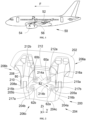
- FIG. 1 shows an aircraft 50 which has a wing 52 under which is mounted an engine 54 such as a turbojet.
- the engine 54 is mounted by means of a mast 56 which has a structure fixed between a structure of the wing 52 and a structure of the engine 54.
- X is called the longitudinal direction of the mast 54, this direction X being parallel to a longitudinal axis of the aircraft 50.
- Y is called the transverse direction of the mast 56 which is horizontal when the aircraft 50 is on the ground, and Z is the vertical direction or vertical height when the aircraft 50 is on the ground, these three directions X, Y and Z being orthogonal to each other.
- front and rear are to be considered in relation to a direction of advancement of the aircraft 50 during operation of the engine 54, this direction being represented schematically by the arrow F.
- the terms “port” and “starboard” are also to be considered in relation to the direction of advancement F of the aircraft 50 and in relation to the longitudinal direction X.
- FIG. 2 shows an example of a fixing assembly 200 according to the invention, which ensures the fixing of the structure 202 of the wing 52 to the structure 204 of the mast 56.
- the mast 56 takes for example the form of a box and it comprises, among other things, two side walls 204a-b, namely a port side wall 204a and a starboard side wall 204b and between the side walls 204a-b, a central fitting 204c, called the second central fitting 204c, which is generally perpendicular to said side walls 204a-b and fixed between them.
- the second central fitting 204c is generally perpendicular to the longitudinal direction X and the side walls 204a-b are generally parallel to a median plane XZ of the mast 56.
- the second central fitting 204c can take the form of a wall constituting an internal rib of the mast 56.
- the second central fitting 204c is thus integral with the structure 204 of the mast 56.
- the fixing assembly 200 comprises two lateral fixings 206a-b, namely a port lateral fixing 206a and a starboard lateral fixing 206b, and a central fixing system 206c according to the invention which ensures the fixing of the structure 202 of the wing 52 to the structure 204 of the mast 56.
- Each lateral attachment 206a-b is here identical to the lateral attachments of the prior art.
- the lateral attachments 206a-b are given here as an example but are not part of the invention, and serve only to give an example of implementation of the invention.
- Each lateral attachment 206a-b comprises a lateral fitting 208 which is fixed to the structure 202 of the wing 52 and which has a female yoke 208a in which the lateral wall 204a-b of the mast 56 which is on the same side is inserted.
- the female yoke 208a and the associated lateral wall 204a-b are secured by an axis 210 passing through said female yoke 208a and said lateral wall 204a-b through bores provided for this purpose.
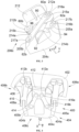
- FIG. 3 shows the central fixing system 206c according to a particular embodiment of the invention.
- the X direction is also a longitudinal direction X for the central fixing system 206c which comprises a first central fitting 212 secured to the structure 202 of the wing 52 and having two first yokes 212a-b, namely 212a one on the port side and 212b one on the starboard side.
- the first central fitting 212 is formed in a single piece, so as to correspond to a single and unique first central fitting 212.
- the central fixing system 206c also comprises the second central fitting 204c having two second yokes 205a-b, namely one 205a on the port side and one 205b on the starboard side.
- the central fixing system 206c also comprises two connecting systems 214a-b, namely a first connecting system 214a and a second connecting system 214b.
- Each connecting system 214a-b has a third yoke 215a-b and a fourth yoke 217a-b.
- the connecting systems 214a-b ensure the transfer of transverse forces applied to the mast 56.
- Each first yoke 212a-b is hingedly attached to a third yoke 215a-b so as to form a first articulation point, namely a first articulation point 60a on the port side for the first port yoke 212a, and a first articulation point 60b on the starboard side for the first starboard yoke 212b.
- Each second yoke 205a-b is hingedly attached to a fourth yoke 217b-a so as to form a second hinge point, namely a second hinge point 62a on the port side for the second port yoke 205a, and a second hinge point 62b on the starboard side for the second starboard yoke 205b.
- the first connection system 214a is thus fixed in an articulated manner between the first articulation point 60a on the port side and the second articulation point 62b on the starboard side
- the second connection system 214b is thus fixed in an articulated manner between the first articulation point 60b on the starboard side and the second articulation point 62a on the port side.
- the third yoke 215a of the first connecting system 214a is mounted articulated with the first port yoke 212a of the first central fitting 212 at the first articulation point 60a on the port side
- the third yoke 215b of the second connecting system 214b is mounted articulated with the first starboard yoke 212b of the first central fitting 212 at the first articulation point 60b on the starboard side
- the fourth yoke 217a of the first connecting system 214a is mounted articulated with the second starboard yoke 205b of the second central fitting 204c at the second articulation point 62b on the starboard side
- the fourth yoke 217b of the second connecting system 214b is mounted articulated with the second port yoke 205a of the second central fitting 204c at the second articulation point 62a on the port side.
- the two connecting systems 214a-b are thus crossed and depending on the angle at the crossing, the vertical space requirement can be reduced compared to the state of the art.
- the angle at the crossing is reduced.
- each articulation point of the central fixing system 206c the fixing between two yokes is carried out by an axis 216a-b passing through each yoke considered through orifices provided for this purpose and each articulation point corresponds to an axis which is parallel to the longitudinal direction X.
- Each yoke 212a-b, 205a-b, 215a-b, 217a-b of the central fixing system 206c thus has a bore whose axis is parallel to the longitudinal direction X.
- the first connecting system 214a takes the form of two connecting rods 90 and 92 arranged on either side of the first port yoke 212a of the first central fitting 212 and on either side of the second starboard yoke 205b of the second central fitting 204c. Together, the two connecting rods 90 and 92 form the third yoke 215a and the fourth yoke 217a of the first connecting system 214a and these are so-called female yokes.
- the first port yoke 212a of the first central fitting 212 and the second starboard yoke 205b of the second central fitting 204c each form a so-called male yoke which is inserted into the corresponding female yoke.
- a female yoke takes the form of a stirrup with two parallel walls, each of which is crossed by a bore for the installation of the pin.
- a male yoke takes the form of a wall crossed by a bore for the installation of the pin.
- the second connecting system 214b takes the form of a connecting rod, a first end of which takes the form of a female yoke 94 with two parallel walls and the other end of which takes the form of a male yoke 96.
- said female yoke 94 forms the fourth yoke 217b of the second connecting system 214b and the male yoke 96 forms the third yoke 215b of the second connecting system 214b.
- the second port yoke 205a of the second central fitting 204c then forms a male yoke which is inserted into the female yoke 94 of the second connecting system 214b.
- the first starboard yoke 212b of the first central fitting 212 then forms a female yoke into which the male yoke 96 of the second connecting system 214b is inserted.
- the connecting rod forming the second connecting system 214b is inserted between the two connecting rods 90 and 92 forming the first connecting system 214a.
- the second connecting system 214b can also take the form of two connecting rods arranged on either side of the first starboard yoke 212b of the first central fitting 212 and on either side of the second yoke 205a of the second central fitting 204c, to together form the third yoke 215b and the fourth yoke 217b of the second connecting system 214b.
- At least one of the first connecting system 214a and the second connecting system 214b takes the form of two connecting rods 90 and 92 arranged on either side of the first yoke 212a-b associated with the first central fitting 212 and on either side of the second yoke 205b-a associated with the second central fitting 204c, and together, the two connecting rods 90 and 92 form the third yoke 215a-b and the fourth yoke 217a-b of the connecting system 214a-b considered.
- Each first yoke 212a-b of the first central fitting 212 and each second yoke 205a of the second central fitting 204c which are concerned each take the form of a male yoke which is inserted into the female yoke considered.
- the connecting rods are offset along the longitudinal direction X, with a connecting rod of a first connecting system 214a-b, then a connecting rod of a second connecting system 214b-a, then a connecting rod of the first connecting system 214a-b, then a connecting rod of the second connecting system 214b-a.
- the first connecting system 214a can also take the form of a connecting rod, a first end of which takes the form of a female yoke and the second end of which takes the form of a male yoke.
- the positions of the male yoke and the female yoke can be reversed with respect to the first central fitting 212 and the second central fitting 204c.
- At least one of the first connecting system 214a and the second connecting system 214b takes the form of a connecting rod, a first end of which takes the form of a female yoke 94 and the other end of which takes the form of a male yoke 96 and said female yoke 94 forms one of the third yoke 215a-b and the fourth yoke 217a-b of the connecting system 214a-b considered, and said male yoke 96 forms the other of the fourth yoke 217a-b and the third yoke 215a-b of the connecting system 214a-b considered.
- Each first yoke 212a-b of the first central fitting 212 and each second yoke 205a of the second central fitting 204c which are concerned each take the appropriate form, that is to say a male yoke when it cooperates with a female yoke and vice versa.
- a connecting rod may have a female yoke at each end.
- each end takes the form of a female yoke and one forms the fourth yoke 217b of the second connecting system 214b and the other forms the third yoke 215b of the second connecting system 214b.
- the second port yoke 205a of the second central fitting 204c then forms a male yoke which is inserted into one of the female yokes of the second connecting system 214b and the first starboard yoke 212b of the first central fitting 212 then forms a male yoke which is inserted into the other of the female yokes of the second connecting system 214b.
- At least one of the first connecting system 214a and the second connecting system 214b takes the form of a connecting rod, each end of which takes the form of a female yoke and one of the female yokes forms one of the third yoke 215a-b and the fourth yoke 217a-b of the connecting system 214a-b considered, and the other of the female yokes forms the other of the fourth yoke 217a-b and the third yoke 215a-b of the connecting system 214a-b considered.
- Each first yoke 212a-b of the first central fitting 212 and each second yoke 205a of the second central fitting 204c which are concerned each take the form of a male yoke to cooperate with a female yoke.
- a connecting rod may have a male yoke at each end.
- each end takes the form of a male yoke and one forms the fourth yoke 217b of the second connecting system 214b and the other forms the third yoke 215b of the second connecting system 214b.
- the second port yoke 205a of the second central fitting 204c then forms a female yoke into which one of the male yokes of the second connecting system 214b is inserted and the first starboard yoke 212b of the first central fitting 212 then forms a female yoke into which the other of the male yokes of the second connecting system 214b is inserted.
- At least one of the first connecting system 214a and the second connecting system 214b takes the form of a connecting rod, each end of which takes the form of a male yoke and one of the male yokes forms one of the third yoke 215a-b and the fourth yoke 217a-b of the connecting system 214a-b considered, and the other of the yokes males form the other among the fourth yoke 217a-b and the third yoke 215a-b of the connection system 214a-b considered.
- Each first yoke 212a-b of the first central fitting 212 and each second yoke 205a of the second central fitting 204c which are concerned each take the form of a female yoke to cooperate with a male yoke.
Landscapes
- Engineering & Computer Science (AREA)
- Aviation & Aerospace Engineering (AREA)
- General Engineering & Computer Science (AREA)
- Mechanical Engineering (AREA)
- Mutual Connection Of Rods And Tubes (AREA)
Abstract
Description
- La présente invention se rapporte au domaine général de l'accrochage d'un turboréacteur sous la voilure d'un aéronef. Elle concerne en particulier un système central de fixation pour aéronef qui assure la fixation d'une structure d'une aile à une structure d'un mât de l'aéronef. La présente invention concerne également un aéronef équipé d'un tel système central de fixation.
- Un aéronef de l'état de la technique comporte une aile, un mât fixé sous l'aile et un moteur, tel qu'un turboréacteur, fixé sous le mât.
- La
Fig. 4 montre un exemple d'un ensemble de fixation 400 de l'état de la technique qui assure la fixation d'une structure 402 de l'aile à une structure 404 du mât. Le mât prend classiquement la forme d'un caisson qui comporte, entre autres, deux parois latérales 404a-b, à savoir une paroi latérale bâbord 404a et une paroi latérale tribord 404b et entre les parois latérales 404a-b, une première ferrure centrale 404c qui est globalement perpendiculaire auxdites parois latérales 404a-b et qui peut prendre la forme d'une paroi. - Dans l'exemple de la
Fig. 4 , l'ensemble de fixation 400 comporte deux fixations latérales 406a-b, à savoir une fixation latérale bâbord 406a et une fixation latérale tribord 406b, et un système central de fixation 406c. - Chaque fixation latérale 406a-b comporte une deuxième ferrure latérale 408 qui est fixée à la structure 402 de l'aile et qui présente une chape femelle 408a dans laquelle s'insère la paroi latérale 404a-b qui est du même côté. Pour chaque côté, la chape femelle 408a et la paroi latérale 404a-b associée sont solidarisées par un axe 410 traversant ladite chape femelle 408a et ladite paroi latérale 404a-b à travers des alésages prévus à cet effet.
- Le système central de fixation 406c comporte une ferrure centrale 412 fixée à la structure 402 de l'aile et présentant deux chapes mâles 412a-b, et quatre bielles 414 réparties par paires. Pour chaque paire de bielles 414, les bielles 414 de la paire sont disposées de part et d'autre d'une chape mâle 412a-b pour former une chape femelle dans laquelle ladite chape mâle 412a-b est logée.
- Le système central de fixation 406c comporte également la première ferrure centrale 404c formant deux chapes mâles 405a-b et pour chaque paire de bielles 414, les bielles 414 de la paire sont également disposées de part et d'autre de l'une des chapes mâles 405a-b de la première ferrure centrale 404c pour former une chape femelle dans laquelle ladite chape mâle 405a-b est logée. Il y a une paire de bielles 414 qui est disposée à bâbord et une à tribord. Pour chaque paire de bielles 414, il est prévu un axe 416a, 416b qui traverse les deux bielles 414 de la paire et selon le cas une chape mâle 412a-b de la ferrure centrale 412 ou une chape mâle 405a-b de la première ferrure centrale 404c à travers des alésages prévus à cet effet. Chaque paire de bielles 414 présente ainsi un premier point d'articulation au niveau de la chape mâle 412a-b de la ferrure centrale 412 et un deuxième point d'articulation au niveau de la chape mâle 405a-b de la première ferrure centrale 404c et les deux premiers points d'articulation sont rapprochés l'un de l'autre tandis que les deuxièmes points d'articulation sont éloignés l'un de l'autre.
- Si un tel arrangement est performant, il est relativement encombrant selon la direction verticale.
- Le document
US2018346137 divulgue un ensemble de fixation de moteur d'aéronef selon l'art antérieur. Cet ensemble de fixation comprenant notamment des fixations distinctes d'une section d'aile de l'aéronef, une fixation sur le mât du moteur, ainsi que des bielles de liaison des fixations de l'aile à la fixation du mât, ces bielles étant disposées de sorte à ne pas se croiser les unes avec les autres. - Un objet de la présente invention est de proposer un système central de fixation pour aéronef, où le système de fixation assure la fixation entre une structure d'une aile et une structure d'un mât, et où le système de fixation présente un dimensionnement vertical réduit par rapport à l'état de la technique.
- À cet effet, est proposé un système central de fixation destiné à la fixation d'une structure d'une aile d'un aéronef à une structure d'un mât dudit aéronef, ledit système central de fixation présentant une direction longitudinale et comportant :
- une première ferrure centrale destinée à être solidaire de la structure de l'aile et présentant une première chape bâbord et une première chape tribord, où chaque première chape présente un alésage dont l'axe est parallèle à la direction longitudinale,
- une deuxième ferrure centrale destinée à être solidaire de la structure du mât et présentant une deuxième chape bâbord et une deuxième chape tribord, où chaque deuxième chape présente un alésage dont l'axe est parallèle à la direction longitudinale,
- un premier système de liaison et un deuxième système de liaison, chacun présentant une troisième chape et une quatrième chape, où chaque troisième et quatrième chapes présentent un alésage dont l'axe est parallèle à la direction longitudinale, où la troisième chape du premier système de liaison est montée articulée avec la première chape bâbord de la première ferrure centrale au niveau d'un premier point d'articulation à bâbord, où la troisième chape du deuxième système de liaison est montée articulée avec la première chape tribord de la première ferrure centrale au niveau d'un premier point d'articulation à tribord, où la quatrième chape du premier système de liaison est montée articulée avec la deuxième chape tribord de la deuxième ferrure centrale au niveau d'un deuxième point d'articulation à tribord, et où la quatrième chape du deuxième système de liaison est montée articulée avec la deuxième chape bâbord de la deuxième ferrure centrale au niveau d'un deuxième point d'articulation à bâbord, et
- pour chaque point d'articulation, un axe monté dans les alésages des chapes correspondantes.
- Avec un tel arrangement, l'encombrement vertical est réduit par rapport à l'état de la technique. De plus, un tel arrangement favorise la tolérance aux dommages en isolant chaque point d'articulation.
- Avantageusement, au moins l'un parmi le premier système de liaison et le deuxième système de liaison prend la forme de deux bielles disposées de part et d'autre de la première chape associée de la première ferrure centrale et de part et d'autre de la deuxième chape associée de la deuxième ferrure centrale, et ensemble, les deux bielles forment la troisième chape et la quatrième chape du système de liaison considéré.
- Avantageusement, au moins l'un parmi le premier système de liaison et le deuxième système de liaison prend la forme d'une bielle dont au moins une première extrémité prend la forme d'une chape femelle et ladite chape femelle forme l'une parmi la troisième chape et la quatrième chape du système de liaison considéré.
- Avantageusement, une deuxième extrémité de la bielle formée par l'un parmi le premier système de liaison et le deuxième système de liaison prend la forme d'une chape mâle et ladite chape mâle forme l'autre parmi la quatrième chape et la troisième chape du système de liaison considéré.
- Avantageusement, une deuxième extrémité de la bielle formée par l'un parmi le premier système de liaison et le deuxième système de liaison prend la forme d'une chape femelle et ladite chape femelle forme l'autre parmi la quatrième chape et la troisième chape du système de liaison considéré.
- Avantageusement, au moins l'un parmi le premier système de liaison et le deuxième système de liaison prend la forme d'une bielle dont chaque extrémité prend la forme d'une chape mâle et l'une des chapes mâles forme l'une parmi la troisième chape et la quatrième chape du système de liaison considéré, et l'autre des chapes mâles forme l'autre parmi la quatrième chape et la troisième chape du système de liaison considéré.
- L'invention propose également un aéronef comportant une aile avec une structure, un mât avec une structure et un système de fixation selon l'une des variantes précédentes, où la première ferrure centrale est solidaire de la structure de l'aile et où la deuxième ferrure centrale est solidaire de la structure du mât.
- Les caractéristiques de l'invention mentionnées ci-dessus, ainsi que d'autres, apparaîtront plus clairement à la lecture de la description suivante d'un exemple de réalisation, ladite description étant faite en relation avec les dessins joints, parmi lesquels :
-
Fig. 1 représente une vue de côté d'un aéronef selon l'invention, -
Fig. 2 est une vue en perspective d'un ensemble de fixation comportant un exemple d'un système central de fixation selon l'invention, -
Fig. 3 est une vue en perspective d'un exemple d'un système central de fixation selon l'invention, et -
Fig. 4 est une vue en perspective d'un ensemble de fixation de l'état de la technique. - La
Fig. 1 montre un aéronef 50 qui présente une aile 52 sous laquelle est monté un moteur 54 tel qu'un turboréacteur. Le moteur 54 est monté par l'intermédiaire d'un mât 56 qui présente une structure fixée entre une structure de l'aile 52 et une structure du moteur 54. - Par convention, on appelle X la direction longitudinale du mât 54, cette direction X étant parallèle à un axe longitudinal de l'aéronef 50. D'autre part, on appelle Y la direction transversale du mât 56 qui est horizontale lorsque l'aéronef 50 est au sol, et Z la direction verticale ou hauteur verticale lorsque l'aéronef 50 est au sol, ces trois directions X, Y et Z étant orthogonales entre elles.
- D'autre part, les termes " avant " et " arrière " sont à considérer par rapport à une direction d'avancement de l'aéronef 50 lors du fonctionnement du moteur 54, cette direction étant représentée schématiquement par la flèche F. Les termes « bâbord » et « tribord » sont également à considérer par rapport à la direction d'avancement F de l'aéronef 50 et par rapport à la direction longitudinale X.
- La
Fig. 2 montre un exemple d'un ensemble de fixation 200 selon l'invention, qui assure la fixation de la structure 202 de l'aile 52 à la structure 204 du mât 56. Le mât 56 prend par exemple la forme d'un caisson et il comporte, entre autres, deux parois latérales 204a-b, à savoir une paroi latérale bâbord 204a et une paroi latérale tribord 204b et entre les parois latérales 204a-b, une ferrure centrale 204c, dite deuxième ferrure centrale 204c, qui est globalement perpendiculaire auxdites parois latérales 204a-b et fixée entre elles. La deuxième ferrure centrale 204c est globalement perpendiculaire à la direction longitudinale X et les parois latérales 204a-b sont globalement parallèles à un plan médian XZ du mât 56. La deuxième ferrure centrale 204c peut prendre la forme d'une paroi constituant une nervure intérieure du mât 56. La deuxième ferrure centrale 204c est ainsi solidaire de la structure 204 du mât 56. - Dans l'exemple de la
Fig. 2 , l'ensemble de fixation 200 comporte deux fixations latérales 206a-b, à savoir une fixation latérale bâbord 206a et une fixation latérale tribord 206b, et un système central de fixation 206c selon l'invention qui assure la fixation de la structure 202 de l'aile 52 à la structure 204 du mât 56. - Chaque fixation latérale 206a-b est ici identique aux fixations latérales de l'état de la technique. Les fixations latérales 206a-b sont données ici à titre d'exemple mais ne font pas partie de l'invention, et servent juste à donner un exemple d'implémentation de l'invention. Chaque fixation latérale 206a-b comporte une ferrure latérale 208 qui est fixée à la structure 202 de l'aile 52 et qui présente une chape femelle 208a dans laquelle s'insère la paroi latérale 204a-b du mât 56 qui est du même côté. Pour chaque côté, la chape femelle 208a et la paroi latérale 204a-b associée sont solidarisées par un axe 210 traversant ladite chape femelle 208a et ladite paroi latérale 204a-b à travers des alésages prévus à cet effet.
- La
Fig. 3 montre le système central de fixation 206c selon un mode de réalisation particulier de l'invention. - La direction X est également une direction longitudinale X pour le système central de fixation 206c qui comporte une première ferrure centrale 212 solidaire de la structure 202 de l'aile 52 et présentant deux premières chapes 212a-b, à savoir 212a une à bâbord et une 212b à tribord. La première ferrure centrale 212 est formée en une seule pièce, de sorte à correspondre à une seule et unique première ferrure centrale 212.
- Le système central de fixation 206c comporte également la deuxième ferrure centrale 204c présentant deux deuxièmes chapes 205a-b, à savoir une 205a à bâbord et une 205b à tribord.
- Le système central de fixation 206c comporte également deux systèmes de liaison 214a-b, à savoir un premier système de liaison 214a et un deuxième système de liaison 214b. Chaque système de liaison 214a-b présente une troisième chape 215a-b et une quatrième chape 217a-b. Les systèmes de liaison 214a-b assurent le transfert des efforts transverses appliqués au mât 56.
- Chaque première chape 212a-b est fixée de manière articulée à une troisième chape 215a-b de manière à former un premier point d'articulation, à savoir un premier point d'articulation 60a à bâbord pour la première chape bâbord 212a, et un premier point d'articulation 60b à tribord pour la première chape tribord 212b.
- Chaque deuxième chape 205a-b est fixée de manière articulée à une quatrième chape 217b-a de manière à former un deuxième point d'articulation, à savoir un deuxième point d'articulation 62a à bâbord pour la deuxième chape bâbord 205a, et un deuxième point d'articulation 62b à tribord pour la deuxième chape tribord 205b.
- Le premier système de liaison 214a est ainsi fixé de manière articulée entre le premier point d'articulation 60a à bâbord et le deuxième point d'articulation 62b à tribord, et le deuxième système de liaison 214b est ainsi fixé de manière articulée entre le premier point d'articulation 60b à tribord et le deuxième point d'articulation 62a à bâbord.
- En d'autres termes, la troisième chape 215a du premier système de liaison 214a est montée articulée avec la première chape bâbord 212a de la première ferrure centrale 212 au niveau du premier point d'articulation 60a à bâbord, la troisième chape 215b du deuxième système de liaison 214b est montée articulée avec la première chape tribord 212b de la première ferrure centrale 212 au niveau du premier point d'articulation 60b à tribord, la quatrième chape 217a du premier système de liaison 214a est montée articulée avec la deuxième chape tribord 205b de la deuxième ferrure centrale 204c au niveau du deuxième point d'articulation 62b à tribord, et la quatrième chape 217b du deuxième système de liaison 214b est montée articulée avec la deuxième chape bâbord 205a de la deuxième ferrure centrale 204c au niveau du deuxième point d'articulation 62a à bâbord.
- Les deux systèmes de liaison 214a-b sont donc croisés et en fonction de l'angle au niveau du croisement, l'encombrement vertical peut être réduit par rapport à l'état de la technique. En particulier, en écartant latéralement les premiers points d'articulation 60a-b l'un de l'autre et les deuxièmes points d'articulation 62a-b l'un de l'autre, l'angle au niveau du croisement se réduit.
- Au niveau de chaque point d'articulation du système central de fixation 206c, la fixation entre deux chapes est réalisée par un axe 216a-b traversant chaque chape considérée à travers des orifices prévus à cet effet et chaque point d'articulation correspond à un axe qui est parallèle à la direction longitudinale X. Chaque chape 212a-b, 205a-b, 215a-b, 217a-b du système central de fixation 206c présente ainsi un alésage dont l'axe est parallèle à la direction longitudinale X.
- Dans le mode de réalisation de l'invention présenté à la
Fig. 3 , le premier système de liaison 214a prend la forme de deux bielles 90 et 92 disposées de part et d'autre de la première chape bâbord 212a de la première ferrure centrale 212 et de part et d'autre de la deuxième chape tribord 205b de la deuxième ferrure centrale 204c. Ensemble, les deux bielles 90 et 92 forment la troisième chape 215a et la quatrième chape 217a du premier système de liaison 214a et ce sont des chapes dites femelles. La première chape bâbord 212a de la première ferrure centrale 212 et la deuxième chape tribord 205b de la deuxième ferrure centrale 204c forment chacune une chape dite mâle qui s'insère dans la chape femelle correspondante. - Une chape femelle prend la forme d'un étrier avec deux parois parallèles, où chacune est traversée par un alésage pour la mise en place de l'axe. Une chape mâle prend la forme d'une paroi traversée par un alésage pour la mise en place de l'axe.
- Dans le mode de réalisation de l'invention présenté à la
Fig. 3 , le deuxième système de liaison 214b prend la forme d'une bielle dont une première extrémité prend la forme d'une chape femelle 94 avec deux parois parallèles et dont l'autre extrémité prend la forme d'une chape mâle 96. Ici, ladite chape femelle 94 forme la quatrième chape 217b du deuxième système de liaison 214b et la chape mâle 96 forme la troisième chape 215b du deuxième système de liaison 214b. La deuxième chape bâbord 205a de la deuxième ferrure centrale 204c forme alors une chape mâle qui s'insère dans la chape femelle 94 du deuxième système de liaison 214b. La première chape tribord 212b de la première ferrure centrale 212 forme alors une chape femelle dans laquelle s'insère la chape mâle 96 du deuxième système de liaison 214b. Dans le mode de réalisation de l'invention présenté à laFig. 3 , la bielle formant le deuxième système de liaison 214b est insérée entre les deux bielles 90 et 92 formant le premier système de liaison 214a. - En cas de rupture au niveau de l'un des systèmes de liaison 214a-b, il est nécessaire d'assurer la continuité du transfert des efforts vers l'aile 52.
- Avec un tel arrangement, si l'une des bielles 90, 92 du premier système de liaison 214a est rompue, elle est compensée par l'autre bielle 92, 90. Si les deux bielles 90, 92 du premier système de liaison 214a sont rompues, elles sont compensées par la bielle du deuxième système de liaison 214b. Si la bielle du deuxième système de liaison 214b est rompue, elle est compensée par les bielles 90, 92 du premier système de liaison 214a.
- D'autres modes de réalisation (non représentés) sont envisageables à partir du mode de réalisation représenté à la
Fig. 3 . - Par exemple, le deuxième système de liaison 214b peut également prendre la forme de deux bielles disposées de part et d'autre de la première chape tribord 212b de la première ferrure centrale 212 et de part et d'autre de la deuxième chape 205a de la deuxième ferrure centrale 204c, pour former ensemble la troisième chape 215b et la quatrième chape 217b du deuxième système de liaison 214b.
- Ainsi d'une manière générale, au moins l'un parmi le premier système de liaison 214a et le deuxième système de liaison 214b prend la forme de deux bielles 90 et 92 disposées de part et d'autre de la première chape 212a-b associée de la première ferrure centrale 212 et de part et d'autre de la deuxième chape 205b-a associée de la deuxième ferrure centrale 204c, et ensemble, les deux bielles 90 et 92 forment la troisième chape 215a-b et la quatrième chape 217a-b du système de liaison 214a-b considéré.
- Chaque première chape 212a-b de la première ferrure centrale 212 et chaque deuxième chape 205a de la deuxième ferrure centrale 204c qui sont concernées prennent chacune la forme d'une chape mâle qui s'insère dans la chape femelle considérée.
- Dans le cas où les deux systèmes de liaison 214a-b sont constitués de deux bielles 90 et 92, les bielles sont décalées le long de la direction longitudinale X, avec une bielle d'un premier système de liaison 214a-b, puis une bielle d'un deuxième système de liaison 214b-a, puis une bielle du premier système de liaison 214a-b, puis une bielle du deuxième système de liaison 214b-a.
- Par exemple, le premier système de liaison 214a peut également prendre la forme d'une bielle dont une première extrémité prend la forme d'une chape femelle et dont la deuxième extrémité prend la forme d'une chape mâle.
- Pour le premier système de liaison 214a comme pour le deuxième système de liaison 214b, les positions de la chape mâle et de la chape femelle peuvent être inversées par rapport à la première ferrure centrale 212 et à la deuxième ferrure centrale 204c.
- Ainsi, d'une manière générale, au moins l'un parmi le premier système de liaison 214a et le deuxième système de liaison 214b prend la forme d'une bielle dont une première extrémité prend la forme d'une chape femelle 94 et dont l'autre extrémité prend la forme d'une chape mâle 96 et ladite chape femelle 94 forme l'une parmi la troisième chape 215a-b et la quatrième chape 217a-b du système de liaison 214a-b considéré, et ladite chape mâle 96 forme l'autre parmi la quatrième chape 217a-b et la troisième chape 215a-b du système de liaison 214a-b considéré.
- Chaque première chape 212a-b de la première ferrure centrale 212 et chaque deuxième chape 205a de la deuxième ferrure centrale 204c qui sont concernées prennent chacune la forme appropriée, c'est-à-dire une chape mâle lorsqu'elle coopère avec une chape femelle et inversement.
- Par exemple, une bielle peut avoir une chape femelle à chaque extrémité. Ainsi, pour le deuxième système de liaison 214b, chaque extrémité prend la forme d'une chape femelle et l'une forme la quatrième chape 217b du deuxième système de liaison 214b et l'autre forme la troisième chape 215b du deuxième système de liaison 214b. La deuxième chape bâbord 205a de la deuxième ferrure centrale 204c forme alors une chape mâle qui s'insère dans l'une des chapes femelles du deuxième système de liaison 214b et la première chape tribord 212b de la première ferrure centrale 212 forme alors une chape mâle qui s'insère l'autre des chapes femelles du deuxième système de liaison 214b.
- Ainsi, d'une manière générale, au moins l'un parmi le premier système de liaison 214a et le deuxième système de liaison 214b prend la forme d'une bielle dont chaque extrémité prend la forme d'une chape femelle et l'une des chapes femelles forme l'une parmi la troisième chape 215a-b et la quatrième chape 217a-b du système de liaison 214a-b considéré, et l'autre des chapes femelles forme l'autre parmi la quatrième chape 217a-b et la troisième chape 215a-b du système de liaison 214a-b considéré.
- Chaque première chape 212a-b de la première ferrure centrale 212 et chaque deuxième chape 205a de la deuxième ferrure centrale 204c qui sont concernées prennent chacune la forme d'une chape mâle pour coopérer avec une chape femelle.
- Par exemple, une bielle peut avoir une chape mâle à chaque extrémité. Ainsi, pour le deuxième système de liaison 214b, chaque extrémité prend la forme d'une chape mâle et l'une forme la quatrième chape 217b du deuxième système de liaison 214b et l'autre forme la troisième chape 215b du deuxième système de liaison 214b. La deuxième chape bâbord 205a de la deuxième ferrure centrale 204c forme alors une chape femelle dans laquelle s'insère l'une des chapes mâles du deuxième système de liaison 214b et la première chape tribord 212b de la première ferrure centrale 212 forme alors une chape femelle dans laquelle s'insère l'autre des chapes mâles du deuxième système de liaison 214b.
- Ainsi, d'une manière générale, au moins l'un parmi le premier système de liaison 214a et le deuxième système de liaison 214b prend la forme d'une bielle dont chaque extrémité prend la forme d'une chape mâle et l'une des chapes mâles forme l'une parmi la troisième chape 215a-b et la quatrième chape 217a-b du système de liaison 214a-b considéré, et l'autre des chapes mâles forme l'autre parmi la quatrième chape 217a-b et la troisième chape 215a-b du système de liaison 214a-b considéré.
- Chaque première chape 212a-b de la première ferrure centrale 212 et chaque deuxième chape 205a de la deuxième ferrure centrale 204c qui sont concernées prennent chacune la forme d'une chape femelle pour coopérer avec une chape mâle.
Claims (7)
- Système central de fixation (206c) destiné à la fixation d'une structure (202) d'une aile (52) d'un aéronef (50) à une structure (204) d'un mât (56) dudit aéronef (50), ledit système central de fixation (206c) présentant une direction longitudinale (X) et comportant :- une première ferrure centrale (212) destinée à être solidaire de la structure (202) de l'aile (52) et présentant une première chape bâbord (212a) et une première chape tribord (212b), où chaque première chape (212a-b) présente un alésage dont l'axe est parallèle à la direction longitudinale (X),- une deuxième ferrure centrale (204c) destinée à être solidaire de la structure (204) du mât (56) et présentant une deuxième chape bâbord (205a) et une deuxième chape tribord (205b), où chaque deuxième chape (205a-b) présente un alésage dont l'axe est parallèle à la direction longitudinale (X),- un premier système de liaison (214a) et un deuxième système de liaison (214b), chacun présentant une troisième chape (215a-b) et une quatrième chape (217a-b), où chaque troisième et quatrième chapes (215a-b, 217a-b) présentent un alésage dont l'axe est parallèle à la direction longitudinale (X), où la troisième chape (215a) du premier système de liaison (214a) est montée articulée avec la première chape bâbord (212a) de la première ferrure centrale (212) au niveau d'un premier point d'articulation (60a) à bâbord, où la troisième chape (215b) du deuxième système de liaison (214b) est montée articulée avec la première chape tribord (212b) de la première ferrure centrale (212) au niveau d'un premier point d'articulation (60b) à tribord, où la quatrième chape (217a) du premier système de liaison (214a) est montée articulée avec la deuxième chape tribord (205b) de la deuxième ferrure centrale (204c) au niveau d'un deuxième point d'articulation (62b) à tribord, et où la quatrième chape (217b) du deuxième système de liaison (214b) est montée articulée avec la deuxième chape bâbord (205a) de la deuxième ferrure centrale (204c) au niveau d'un deuxième point d'articulation (62a) à bâbord, et- pour chaque point d'articulation (60a-b, 62a-b), un axe (216a-b) monté dans les alésages des chapes correspondantes.
- Système central de fixation (206c) selon la revendication 1, caractérisé en ce qu'au moins l'un parmi le premier système de liaison (214a) et le deuxième système de liaison (214b) prend la forme de deux bielles (90, 92) disposées de part et d'autre de la première chape (212a-b) associée de la première ferrure centrale (212) et de part et d'autre de la deuxième chape (205b-a) associée de la deuxième ferrure centrale (204c), et en ce qu'ensemble, les deux bielles (90, 92) forment la troisième chape (215a-b) et la quatrième chape (217a-b) du système de liaison (214a-b) considéré.
- Système central de fixation (206c) selon l'une des revendications 1 ou 2, caractérisé en ce qu'au moins l'un parmi le premier système de liaison (214a) et le deuxième système de liaison (214b) prend la forme d'une bielle dont au moins une première extrémité prend la forme d'une chape femelle (94) et en ce que ladite chape femelle (94) forme l'une parmi la troisième chape (215a-b) et la quatrième chape (217a-b) du système de liaison (214a-b) considéré.
- Système central de fixation (206c) selon la revendication 3, caractérisé en ce qu'une deuxième extrémité de la bielle formée par l'un parmi le premier système de liaison (214a) et le deuxième système de liaison (214b) prend la forme d'une chape mâle (96) et en ce que ladite chape mâle (96) forme l'autre parmi la quatrième chape (217a-b) et la troisième chape (215a-b) du système de liaison (214a-b) considéré.
- Système central de fixation (206c) selon la revendication 3, caractérisé en ce qu'une deuxième extrémité de la bielle formée par l'un parmi le premier système de liaison (214a) et le deuxième système de liaison (214b) prend la forme d'une chape femelle et en ce que ladite chape femelle forme l'autre parmi la quatrième chape (217a-b) et la troisième chape (215a-b) du système de liaison (214a-b) considéré.
- Système central de fixation (206c) selon l'une des revendications 1 à 5, caractérisé en ce qu'au moins l'un parmi le premier système de liaison (214a) et le deuxième système de liaison (214b) prend la forme d'une bielle dont chaque extrémité prend la forme d'une chape mâle et en ce que l'une des chapes mâles forme l'une parmi la troisième chape (215a-b) et la quatrième chape (217a-b) du système de liaison (214a-b) considéré, et l'autre des chapes mâles forme l'autre parmi la quatrième chape (217a-b) et la troisième chape (215a-b) du système de liaison (214a-b) considéré.
- Aéronef (50) comportant une aile (52) avec une structure (202), un mât (56) avec une structure (204) et un système de fixation selon l'une des revendications précédentes, où la première ferrure centrale (212) est solidaire de la structure (202) de l'aile (52) et où la deuxième ferrure centrale (204c) est solidaire de la structure (204) du mât (56).
Applications Claiming Priority (1)
| Application Number | Priority Date | Filing Date | Title |
|---|---|---|---|
| FR2303011 | 2023-03-29 |
Publications (2)
| Publication Number | Publication Date |
|---|---|
| EP4438485A1 true EP4438485A1 (fr) | 2024-10-02 |
| EP4438485B1 EP4438485B1 (fr) | 2026-05-06 |
Family
ID=86942686
Family Applications (1)
| Application Number | Title | Priority Date | Filing Date |
|---|---|---|---|
| EP24166172.7A Active EP4438485B1 (fr) | 2023-03-29 | 2024-03-26 | Système central de fixation pour aéronef assurant la fixation d'une structure d'une aile à une structure d'un mât |
Country Status (3)
| Country | Link |
|---|---|
| US (1) | US12454364B2 (fr) |
| EP (1) | EP4438485B1 (fr) |
| CN (1) | CN118723060A (fr) |
Citations (5)
| Publication number | Priority date | Publication date | Assignee | Title |
|---|---|---|---|---|
| US6095456A (en) * | 1996-12-23 | 2000-08-01 | The Boeing Company | Strut-wing interface having dual upper links |
| US9248921B2 (en) * | 2013-07-11 | 2016-02-02 | Spirit Aerosystems, Inc. | Method for mounting a pylon to an aircraft |
| FR3041935A1 (fr) * | 2015-10-05 | 2017-04-07 | Airbus Operations Sas | Ensemble moteur pour aeronef comprenant au moins deux attaches moteur arriere decalees axialement l'une de l'autre |
| FR3044297A1 (fr) * | 2015-11-27 | 2017-06-02 | Airbus Operations Sas | Ensemble moteur pour aeronef comprenant des attaches moteur arriere sous forme de manilles |
| US20180346137A1 (en) | 2017-06-02 | 2018-12-06 | Spirit Aerosystems, Inc. | Aircraft engine attachment assembly |
Family Cites Families (1)
| Publication number | Priority date | Publication date | Assignee | Title |
|---|---|---|---|---|
| JP6137846B2 (ja) * | 2013-01-25 | 2017-05-31 | 三菱航空機株式会社 | パイロンと翼を連結するリンク部材、航空機のパイロンおよび航空機 |
-
2024
- 2024-03-26 EP EP24166172.7A patent/EP4438485B1/fr active Active
- 2024-03-27 US US18/618,244 patent/US12454364B2/en active Active
- 2024-03-28 CN CN202410365964.XA patent/CN118723060A/zh active Pending
Patent Citations (5)
| Publication number | Priority date | Publication date | Assignee | Title |
|---|---|---|---|---|
| US6095456A (en) * | 1996-12-23 | 2000-08-01 | The Boeing Company | Strut-wing interface having dual upper links |
| US9248921B2 (en) * | 2013-07-11 | 2016-02-02 | Spirit Aerosystems, Inc. | Method for mounting a pylon to an aircraft |
| FR3041935A1 (fr) * | 2015-10-05 | 2017-04-07 | Airbus Operations Sas | Ensemble moteur pour aeronef comprenant au moins deux attaches moteur arriere decalees axialement l'une de l'autre |
| FR3044297A1 (fr) * | 2015-11-27 | 2017-06-02 | Airbus Operations Sas | Ensemble moteur pour aeronef comprenant des attaches moteur arriere sous forme de manilles |
| US20180346137A1 (en) | 2017-06-02 | 2018-12-06 | Spirit Aerosystems, Inc. | Aircraft engine attachment assembly |
Also Published As
| Publication number | Publication date |
|---|---|
| US12454364B2 (en) | 2025-10-28 |
| CN118723060A (zh) | 2024-10-01 |
| US20240327009A1 (en) | 2024-10-03 |
| EP4438485B1 (fr) | 2026-05-06 |
Similar Documents
| Publication | Publication Date | Title |
|---|---|---|
| EP3483069B1 (fr) | Systeme d'attache moteur d'aeronef | |
| CA2696802C (fr) | Dispositif d'accrochage de moteur d'aeronef comportant un dispositif de reprise des efforts de poussee a encombrement reduit | |
| EP2500268B1 (fr) | Mât d'accrochage de moteur pour aéronef | |
| FR2915178A1 (fr) | Attache d'un caisson de mat sur une voilure, pincant un panneau lateral du caisson | |
| EP4144647B1 (fr) | Système d'attache moteur avant pour un moteur d'aéronef qui comporte une structure compacte | |
| FR3068008A1 (fr) | Ensemble de motorisation pour un aeronef | |
| FR3073205A1 (fr) | Attache moteur d'un moteur d'aeronef | |
| WO2008132077A1 (fr) | Mat d'accrochage de moteur pour aeronef disposant d'une attache moteur arriere pourvue d'un ecrou a barillet | |
| EP1773660B1 (fr) | Ensemble moteur pour aeronef | |
| EP4484297B1 (fr) | Système d'attache moteur avant pour un moteur d'aéronef qui comporte une structure compacte | |
| EP3505448A1 (fr) | Ensemble pour aeronef comprenant une structure primaire de mat d'accrochage fixee a un caisson de voilure par des attaches presentant un encombrement reduit dans la zone de bord d'attaque | |
| WO2021104913A1 (fr) | Systeme d'attache moteur avant pour un moteur aéronef qui comporte une structure allégée | |
| EP3486174B1 (fr) | Attache moteur arriere pour un moteur d'aeronef | |
| EP4368512A1 (fr) | Ensemble pour un aéronef comportant une aile et un mât réacteur pour coupler un système de propulsion à ladite aile | |
| EP4484298A1 (fr) | Système d attache moteur avant pour un moteur d aéronef qui comporte une structure compacte | |
| EP4124575B1 (fr) | Ensemble propulsif pour aéronef comportant un turboréacteur, un mât et des moyens d accrochage du turboréacteur au mât | |
| EP4438485B1 (fr) | Système central de fixation pour aéronef assurant la fixation d'une structure d'une aile à une structure d'un mât | |
| EP3715258A1 (fr) | Attache moteur arrière d'un aéronef présentant des biellettes en deux parties et aéronef comprenant au moins une telle attache moteur arrière | |
| EP4484299B1 (fr) | Système d attache moteur avant pour un moteur d aéronef qui comporte une structure compacte | |
| FR3135450A1 (fr) | Assemblage d’un mât réacteur avec une aile d’un aeronef. | |
| EP4438486B1 (fr) | Ensemble propulsif pour aéronef comportant un turboréacteur, un mât et des moyens d'accrochage du turboréacteur au mât | |
| FR3058388A1 (fr) | Attache arriere d'un moteur d'aeronef | |
| EP3705404A1 (fr) | Dispositif de liaison reliant un moteur d'aéronef et une structure primaire d'un mât d'aéronef comprenant un palonnier et un système de limitation du débattement hors plan du palonnier, aéronef comprenant un tel dispositif de liaison | |
| FR3096351A1 (fr) | Systeme d’attache moteur arriere pour un moteur d’aeronef comportant une poutre realisee en trois parties | |
| FR3131734A1 (fr) | Ensemble propulsif pour aéronef comportant un turboréacteur, un mât et des moyens d’accrochage du turboréacteur au mât |
Legal Events
| Date | Code | Title | Description |
|---|---|---|---|
| PUAI | Public reference made under article 153(3) epc to a published international application that has entered the european phase |
Free format text: ORIGINAL CODE: 0009012 |
|
| STAA | Information on the status of an ep patent application or granted ep patent |
Free format text: STATUS: THE APPLICATION HAS BEEN PUBLISHED |
|
| AK | Designated contracting states |
Kind code of ref document: A1 Designated state(s): AL AT BE BG CH CY CZ DE DK EE ES FI FR GB GR HR HU IE IS IT LI LT LU LV MC ME MK MT NL NO PL PT RO RS SE SI SK SM TR |
|
| STAA | Information on the status of an ep patent application or granted ep patent |
Free format text: STATUS: REQUEST FOR EXAMINATION WAS MADE |
|
| 17P | Request for examination filed |
Effective date: 20250327 |
|
| GRAP | Despatch of communication of intention to grant a patent |
Free format text: ORIGINAL CODE: EPIDOSNIGR1 |
|
| STAA | Information on the status of an ep patent application or granted ep patent |
Free format text: STATUS: GRANT OF PATENT IS INTENDED |
|
| INTG | Intention to grant announced |
Effective date: 20251031 |
|
| RIN1 | Information on inventor provided before grant (corrected) |
Inventor name: BERJOT, MICHAEL Inventor name: BONHOMME, PHILIPPE Inventor name: TAVEAU, PAUL-ADRIEN |
|
| GRAS | Grant fee paid |
Free format text: ORIGINAL CODE: EPIDOSNIGR3 |
|
| GRAA | (expected) grant |
Free format text: ORIGINAL CODE: 0009210 |
|
| STAA | Information on the status of an ep patent application or granted ep patent |
Free format text: STATUS: THE PATENT HAS BEEN GRANTED |
|
| AK | Designated contracting states |
Kind code of ref document: B1 Designated state(s): AL AT BE BG CH CY CZ DE DK EE ES FI FR GB GR HR HU IE IS IT LI LT LU LV MC ME MK MT NL NO PL PT RO RS SE SI SK SM TR |
|
| REG | Reference to a national code |
Ref country code: CH Ref legal event code: F10 Free format text: ST27 STATUS EVENT CODE: U-0-0-F10-F00 (AS PROVIDED BY THE NATIONAL OFFICE) Effective date: 20260506 Ref country code: GB Ref legal event code: FG4D Free format text: NOT ENGLISH |