EP4438474A1 - Aircraft transportation for mobile power generation packages - Google Patents
Aircraft transportation for mobile power generation packages Download PDFInfo
- Publication number
- EP4438474A1 EP4438474A1 EP24161492.4A EP24161492A EP4438474A1 EP 4438474 A1 EP4438474 A1 EP 4438474A1 EP 24161492 A EP24161492 A EP 24161492A EP 4438474 A1 EP4438474 A1 EP 4438474A1
- Authority
- EP
- European Patent Office
- Prior art keywords
- trailer
- mobile power
- aircraft
- power plant
- plant system
- Prior art date
- Legal status (The legal status is an assumption and is not a legal conclusion. Google has not performed a legal analysis and makes no representation as to the accuracy of the status listed.)
- Pending
Links
Images



Classifications
-
- B—PERFORMING OPERATIONS; TRANSPORTING
- B64—AIRCRAFT; AVIATION; COSMONAUTICS
- B64F—GROUND OR AIRCRAFT-CARRIER-DECK INSTALLATIONS SPECIALLY ADAPTED FOR USE IN CONNECTION WITH AIRCRAFT; DESIGNING, MANUFACTURING, ASSEMBLING, CLEANING, MAINTAINING OR REPAIRING AIRCRAFT, NOT OTHERWISE PROVIDED FOR; HANDLING, TRANSPORTING, TESTING OR INSPECTING AIRCRAFT COMPONENTS, NOT OTHERWISE PROVIDED FOR
- B64F1/00—Ground or aircraft-carrier-deck installations
- B64F1/32—Ground or aircraft-carrier-deck installations for handling freight
- B64F1/326—Supply vehicles specially adapted for transporting catering to and loading into the aircraft
-
- B—PERFORMING OPERATIONS; TRANSPORTING
- B62—LAND VEHICLES FOR TRAVELLING OTHERWISE THAN ON RAILS
- B62D—MOTOR VEHICLES; TRAILERS
- B62D63/00—Motor vehicles or trailers not otherwise provided for
- B62D63/06—Trailers
-
- B—PERFORMING OPERATIONS; TRANSPORTING
- B62—LAND VEHICLES FOR TRAVELLING OTHERWISE THAN ON RAILS
- B62D—MOTOR VEHICLES; TRAILERS
- B62D63/00—Motor vehicles or trailers not otherwise provided for
- B62D63/06—Trailers
- B62D63/08—Component parts or accessories
-
- B—PERFORMING OPERATIONS; TRANSPORTING
- B64—AIRCRAFT; AVIATION; COSMONAUTICS
- B64D—EQUIPMENT FOR FITTING IN OR TO AIRCRAFT; FLIGHT SUITS; PARACHUTES; ARRANGEMENT OR MOUNTING OF POWER PLANTS OR PROPULSION TRANSMISSIONS IN AIRCRAFT
- B64D9/00—Equipment for handling freight; Equipment for facilitating passenger embarkation or the like
-
- F—MECHANICAL ENGINEERING; LIGHTING; HEATING; WEAPONS; BLASTING
- F01—MACHINES OR ENGINES IN GENERAL; ENGINE PLANTS IN GENERAL; STEAM ENGINES
- F01D—NON-POSITIVE DISPLACEMENT MACHINES OR ENGINES, e.g. STEAM TURBINES
- F01D15/00—Adaptations of machines or engines for special use; Combinations of engines with devices driven thereby
- F01D15/10—Adaptations for driving, or combinations with, electric generators
-
- F—MECHANICAL ENGINEERING; LIGHTING; HEATING; WEAPONS; BLASTING
- F01—MACHINES OR ENGINES IN GENERAL; ENGINE PLANTS IN GENERAL; STEAM ENGINES
- F01D—NON-POSITIVE DISPLACEMENT MACHINES OR ENGINES, e.g. STEAM TURBINES
- F01D25/00—Component parts, details, or accessories, not provided for in, or of interest apart from, other groups
- F01D25/28—Supporting or mounting arrangements, e.g. for turbine casing
-
- B—PERFORMING OPERATIONS; TRANSPORTING
- B66—HOISTING; LIFTING; HAULING
- B66D—CAPSTANS; WINCHES; TACKLES, e.g. PULLEY BLOCKS; HOISTS
- B66D1/00—Rope, cable, or chain winding mechanisms; Capstans
- B66D1/60—Rope, cable, or chain winding mechanisms; Capstans adapted for special purposes
-
- F—MECHANICAL ENGINEERING; LIGHTING; HEATING; WEAPONS; BLASTING
- F02—COMBUSTION ENGINES; HOT-GAS OR COMBUSTION-PRODUCT ENGINE PLANTS
- F02B—INTERNAL-COMBUSTION PISTON ENGINES; COMBUSTION ENGINES IN GENERAL
- F02B63/00—Adaptations of engines for driving pumps, hand-held tools or electric generators; Portable combinations of engines with engine-driven devices
- F02B63/04—Adaptations of engines for driving pumps, hand-held tools or electric generators; Portable combinations of engines with engine-driven devices for electric generators
- F02B63/044—Adaptations of engines for driving pumps, hand-held tools or electric generators; Portable combinations of engines with engine-driven devices for electric generators the engine-generator unit being placed on a frame or in an housing
Definitions
- the present application and the resultant patent relate generally to mobile power generation packages and more particularly relate to systems and methods for transporting and installing mobile power generation packages at remote locations.
- Permanent power plants are built to provide power to customers connected to a power grid. However, there are a variety of reasons that the permanent power plant may not be able to meet the power demands of the customers. For example, in periods of significant growth, the demand by customers may increase to surpass the amount of power that the permanent power plant can generate. In some cases, the permanent plant may be shut down to undergo equipment maintenance. Likewise, blackouts, brownouts, or natural disasters such as a flood, hurricane, earthquakes, and the like may disrupt power production. As a result, mobile power plants may be transported to a location to meet the local power demands of customers when permanent power plants may not be able to deliver power or may not be able to deliver power efficiently. However, environmental issues, such as wind and seismic conditions, may prohibit the installation or operation of mobile power plants. Likewise, the mobile power plant must be well secured during transport, particularly via aircraft when turbulence and the like may be an issue.
- the present application and the resultant patent thus provide a mobile power plant system for loading power generation equipment into an aircraft via a winch cable and secured within the aircraft via a number of aircraft restraints.
- the mobile power plant system includes a trailer with the power generation equipment thereon, a number of hooks attached to the trailer, a winching beam attached to the trailer, and one or more winching shackles attached to the winching beam.
- the winch cable may be attached to the winching shackles to pull the trailer into the aircraft and the aircraft restraints may be attached to the hooks to secure the trailer in the aircraft.
- the present application and the resultant patent further provide a method of method of transporting a mobile power plant system to a remote location.
- the method may include the steps of winching a trailer of the mobile power plant system into an aircraft, securing the trailer with a number of aircraft restraints within the aircraft, driving the trailer to the remote location, and securing the trailer to a foundation of the remote location via a number of turnbuckles attached to the trailer and to the foundation.
- the present application and the resultant patent further provide a mobile power plant system for transporting power generation equipment via an aircraft and securing the power generation equipment at a remote location.
- the mobile power plant system may include a trailer with the power generation equipment thereon, a number of hooks attached to the trailer, a winching beam with one or more winching shackles attached to the trailer, and a tensile restraint with a turnbuckle attached to each of the hooks.
- a winch cable may be attached to the winching shackles to pull the trailer into the aircraft and the tensile restraint with the turnbuckle secures the trailer to the remote location.
- Fig. 1 shows a schematic diagram of a gas turbine engine 10 as may be used herein.
- the gas turbine engine 10 may include a compressor 15.
- the compressor 15 compresses an incoming flow of air 20.
- the compressor 15 delivers the compressed flow of air 20 to a number of combustor cans 25.
- the combustor cans 25 mix the compressed flow of air 20 with a pressurized flow of fuel 30 and ignite the mixture to create a flow of hot combustion gases 35.
- the gas turbine engine 10 may include any number of combustor cans 25 positioned in a circumferential array and the like.
- the combustor 25 may be an annular combustor.
- the flow of combustion gases 35 is in turn delivered to a turbine 40.
- the flow of combustion gases 35 drives the turbine 40 to produce mechanical work.
- the mechanical work produced in the turbine 40 drives the compressor 15 via a rotor shaft 45 and an external load such as an electrical generator 50 and the like.
- the flow of combustion gases 35 is delivered from the turbine 40 to an exhaust frame 55 positioned downstream thereof in the form of spent flue gases.
- the exhaust frame 55 may contain and direct the flow of the flue gases to other components of the gas turbine engine 10.
- the exhaust frame 55 may direct the flow of the flue gases to an exhaust plenum or an exhaust diffuser.
- Other configurations and other components may be used herein.
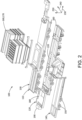
- Fig. 2 is a perspective view of an exemplary mobile power plant system 100 as may be described herein.
- the mobile power plant system 100 may a number of trailers 110.
- a turbine trailer 120, a generator trailer 130, and a control house trailer 140 are shown.
- Other types of trailers 110 may be used herein in any number, size, or configuration.
- Each trailer 110 may be configured to transport one or more of the power generation components of the mobile power plant system 100 to an installation site.
- one or more of the trailers 110 may be coupled to tractors or trucks to be transported to the installation site.
- each of the trailers 110 may include a number of wheels 150 disposed thereon to enable efficient transportation and installation.
- the one or more trailers 110 may be transported via aircraft and the like to a location near the installation site, as further described in detail below. Movement of the one or more components of the mobile power plant system 100 via the trailers 110 and/or aircraft may allow for quicker installation time, lower installation cost, and greater overall mobility.
- the turbine trailer 120 may be configured to transport the gas turbine engine 10 or components thereof. Although a gas turbine is shown, the turbine may be a steam turbine, a hydroturbine, a wind turbine, or any turbine system or other type of power generation equipment. Related components, such as an air intake section 160 with a filter assembly 170 also may be mounted on the turbine trailer 120 or elsewhere. The filter assembly 170 may be configured to filter and intake the air flow into the gas turbine engine 10. Likewise, an auxiliary skid 180 may be disposed at a first end 190 (e.g., opposite a second end 200) of the turbine trailer 120.
- Additional support systems such as a lubrication system, a water wash system, hydraulics system, a fluid injection system, a coolant system, a fuel system, a thermal/clearance system, and the like also may be disposed on the turbine trailer 120 and may be coupled or integrated within the gas turbine engine 10.
- An exhaust stack e.g ., a conduit, a silencer, and emissions control equipment
- Other components and other configurations may be used herein.
- the turbine 40 of the gas turbine engine 10 may drive an external load such as a generator 50.
- the generator 50 may be mounted on the generator trailer 130.
- Various other types of components such as a switch gear to connect the generator 50 to the power grid, a heat exchanger configured to cool generator lube oil, and the like may be mounted on the generator trailer 130.
- Other components and other configurations may be used herein.
- the control house trailer 140 may include a control system configured to monitor and/or regulate the operations of the mobile power plant system 10.
- the control house trailer 140 may include a control house, a battery system, a fire suppression system, a charging system, and/or other systems for controlling or regulating the operations of the mobile power plant system 10.
- Other components and other configurations may be used herein.
- the turbine 40 of the gas turbine engine 10 may be removably coupled to the generator 50 via the common rotor shaft 45.
- the generator 50 may be aligned with the turbine 40 via the generator trailer 130 and the turbine trailer 120.
- a number of restraint assemblies 220 may be coupled to the trailers 110 of the mobile power plant system 100 to maintain alignment of the generator 50 with the turbine 40 despite external loads on the system that may vary over time.
- the rotor shaft 45 may be oriented along a system axis 230.
- the restraint assemblies 220 may be configured to reduce or eliminate movement of the trailers 110 along the system axis 230, one or more lateral axes 240 along a surface of the installation site, along a vertical axis 250, or any combination thereof.
- the restraint assemblies 220 may be configured to limit movement of the turbine trailer 120 relative to the generator trailer 130 to maintain alignment of the rotor shaft 45 and the like.
- the restraint assemblies 220 may be configured to reduce or eliminate movement of the trailers 110 relative to the installation site.
- the restraint assemblies 220 may be coupled to the trailers 110 to maintain a position of the trailers 110 on the one or more foundations at the installation site relative to other components despite external loads (e . g ., wind loads, seismic loads) thereon.
- the restraint assemblies 220 may enable the mobile power plant system 100 to operate despite environmental conditions ( e . g ., winds of 30, 60, 90, or 120 mph or more; seismic events of 0.1 g, 0.25 g, 0.5 g, 0.65 g, or more) that may cause the shutdown of conventional mobile power systems.
- the restraint assembly 220 may enable the mobile power plant system 10 to satisfy one or more building codes for static structures.
- the restraint assemblies 220 and similar restraints may secure the trailers 110 during loading onto an aircraft and during transport on the aircraft.
- the restraint assemblies 220 and similar restraints may secure the trailers 110 during significant turbulence and the like as is described in more detail below.
- the restraint assemblies 220 may include one or more types of restraints.
- the restraint assembly 220 may include one or more tensile restraints 260, one or more fastened restraints 270, or any combination thereof.
- Other types of restraint assemblies 220 may be used herein.
- the restraint assemblies 220 may couple portions of the trailers 110, such a trailer deck 290 or areas adj acent thereto, to one or more foundations 300 at the installation site and/or to any number of cables or other types of restraints on an aircraft.
- the trailers 110 thus may use the restraint assemblies 220 at the installation site for seismic, wind, and other environmental conditions as well as during transport, particularly during transport via aircraft and the like.
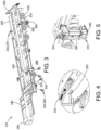
- Fig. 3 shows the turbine trailer 120 at the installation site, i.e., in installation mode.
- the turbine trailer 120 may use a number of the tensile restraints 260 positioned about the first end 190 thereof and elsewhere.
- Each of the tensile restraints 260 may include a turnbuckle 310.
- the turnbuckle 310 i.e., a stretching screw or bottlescrew, is a device for adjusting the tension or length of ropes, cables, tie rods, and/or other types or restraints or tensioning systems. As is shown in Fig.
- the turnbuckle 310 may be attached at one end to the deck 290 via a hook 320 welded thereabout and/or to a welding plate 330. Likewise, the turnbuckle 310 may be attached at the other end to an anchor plate 340. The anchor plate 340 may be secured to the foundation 300 by fasteners or other conventional means. Once attached, the turnbuckle 310 may be tightened to the appropriate tension. Although four tensile restraints 260 are shown on each side of the turbine trailer 120, any number may be used herein.
- the turbine trailer 120 also may use a number of the fastened restraints 270 about the second end 200 thereof and elsewhere.
- the fastened restraints 270 may have one or more rigid elements 350 attached to an anchor plate 340 on a first end 190 and to the deck 290 or adjacent areas of the turbine trailer 120 on the second end 200.
- a first rigid member 360 may be coupled to the anchor plate 340 or the flanges thereof.
- the anchor plate 340 may be fastened to the foundation 300 in a conventional manner.
- a second rigid member 370 may be coupled to the first rigid member 360, may extend in a largely perpendicular direction, and may be fastened to the turbine trailer 120.
- two of the fastened restraints 270 are shown, any number may be used herein. Other configurations and other components may be used herein.
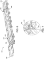
- Fig. 6 shows the turbine trailer 120 in an aircraft, i.e., in aviation mode.
- the turbine trailer 120 may use several of the hooks 320 welded thereto such as those shown in Fig. 4 as well as the hooks 320 attached to the welding plates 330 positioned about the first end 190 and elsewhere.
- the hooks 320 act as lashing points within the aircraft.
- the turbine trailer 120 thus uses those hooks 320 intended for the installation mode as well as dedicated hooks 320 for the aviation mode.
- the turbine trailer 120 may be secured via aircraft restraints 325 such as cables 440, the turnbuckles 310, and the like.
- the turbine trailer 120 also may include a pair or more of winching shackles 380 positioned about the second end 200 thereof. As is shown in Fig. 7 , the winching shackles 380 may be attached to a winching beam 390 via one or more baseplates 400 and fasteners 410. On or more shackles 420 may be attached and supported by the baseplates 400. The winching shackles 380 may be sized to be attached to a winch cable 395 so as to pull the turbine trailer 120 at an angle into an aircraft and the like. Other components and other configurations may be used herein.
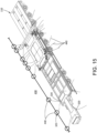
- Fig. 8 shows the generator trailer 130 at the installation site, i.e., in installation mode.
- the generator trailer 130 also may use a number of the tensile restraints 260.
- the tensile restraints 260 may include the turnbuckles 310.
- the generator trailer 130 may have a number hooks 320 or other structures welded to the deck 290 or adjacent thereto.
- the turnbuckles 310 may be attached to the hooks 320 and to the anchor plates 340 and tightened. Any number of the tensile restraints 260 may be used herein.
- the generator trailer 130 also may use a number of the fastened restraints 270 or similar structures. Other configurations and other components may be used herein.
- Fig. 11 shows the generator trailer 130 in an aircraft, i.e., in aviation mode.
- the generator trailer 130 may use several of the hooks 320 welded thereto as lashing points within the aircraft.
- the generator trailer 130 thus uses those hooks 320 intended for the installation mode as well as dedicated hooks 320 for the aviation mode.
- the generator trailer 130 may be secured via the aircraft restraints 325.
- the generator trailer 130 also may include a pair or more of the winching shackles 380 positioned about the second end 200 thereof. As is shown in Fig. 12 , the winching shackles 380 may be attached to the winching beam 390.
- the winching shackles 380 may be sized to be attached to a winch cable 395 so as to pull the generator trailer 130 into an aircraft and the like. As is shown, the winch cable 395 may pull the generator trailer 130 into the aircraft at an angle 385. Other components and other configurations may be used herein.
- Fig. 13 shows the control house trailer 140 at the installation site, i.e., in installation mode.
- the control house trailer 140 also may use a number of the tensile restraints 260.
- the tensile restraints 260 may include the turnbuckles 310.
- the control house trailer 140 may have a number of the hooks 320 or other structures welded to the deck 290 or adjacent thereto.
- the turnbuckles 310 may be attached to the hooks 320 and to the anchor plates 340 and tightened. Any number of the tensile restraints 260 may be used herein.
- the control house trailer 140 also may use a number of the fastened restraints 270 or similar structures. Other configurations and other components may be used herein.
- Fig. 14 shows the control house trailer 140 in an aircraft, i.e., in aviation mode.
- the control house trailer 140 may use several of the hooks 320 welded thereto as lashing points within the aircraft.
- the control house trailer 140 thus uses those the hooks 320 intended for installation mode as well as dedicated hooks 320 for aviation mode.
- the control house trailer 140 may be secured via the aircraft restraints 325 and the like.
- Other components and other configurations may be used herein.
- Fig. 15 shows one of the trailers 110 in aviation mode on an aircraft 430.
- the trailers 110 also may be secured with a number of the aircraft restraints 325.
- the aircraft restraints 325 may be the turnbuckles 310 and/or the cables 440 connected on one end to the hooks 320 on the trailers 110 and to aircraft hooks 450 positioned within the hold of the aircraft 430. Any number of the aircraft restraints 325 or other types of securing devices may used herein. Other components and other configurations may be used herein.
Landscapes
- Engineering & Computer Science (AREA)
- Mechanical Engineering (AREA)
- Aviation & Aerospace Engineering (AREA)
- Transportation (AREA)
- Chemical & Material Sciences (AREA)
- Combustion & Propulsion (AREA)
- General Engineering & Computer Science (AREA)
- Other Liquid Machine Or Engine Such As Wave Power Use (AREA)
- Connection Of Motors, Electrical Generators, Mechanical Devices, And The Like (AREA)
- Wind Motors (AREA)
- Vehicle Cleaning, Maintenance, Repair, Refitting, And Outriggers (AREA)
Abstract
Description
- The present application and the resultant patent relate generally to mobile power generation packages and more particularly relate to systems and methods for transporting and installing mobile power generation packages at remote locations.
- Permanent power plants are built to provide power to customers connected to a power grid. However, there are a variety of reasons that the permanent power plant may not be able to meet the power demands of the customers. For example, in periods of significant growth, the demand by customers may increase to surpass the amount of power that the permanent power plant can generate. In some cases, the permanent plant may be shut down to undergo equipment maintenance. Likewise, blackouts, brownouts, or natural disasters such as a flood, hurricane, earthquakes, and the like may disrupt power production. As a result, mobile power plants may be transported to a location to meet the local power demands of customers when permanent power plants may not be able to deliver power or may not be able to deliver power efficiently. However, environmental issues, such as wind and seismic conditions, may prohibit the installation or operation of mobile power plants. Likewise, the mobile power plant must be well secured during transport, particularly via aircraft when turbulence and the like may be an issue.
- The present application and the resultant patent thus provide a mobile power plant system for loading power generation equipment into an aircraft via a winch cable and secured within the aircraft via a number of aircraft restraints. The mobile power plant system includes a trailer with the power generation equipment thereon, a number of hooks attached to the trailer, a winching beam attached to the trailer, and one or more winching shackles attached to the winching beam. The winch cable may be attached to the winching shackles to pull the trailer into the aircraft and the aircraft restraints may be attached to the hooks to secure the trailer in the aircraft.
- The present application and the resultant patent further provide a method of method of transporting a mobile power plant system to a remote location. The method may include the steps of winching a trailer of the mobile power plant system into an aircraft, securing the trailer with a number of aircraft restraints within the aircraft, driving the trailer to the remote location, and securing the trailer to a foundation of the remote location via a number of turnbuckles attached to the trailer and to the foundation.
- The present application and the resultant patent further provide a mobile power plant system for transporting power generation equipment via an aircraft and securing the power generation equipment at a remote location. The mobile power plant system may include a trailer with the power generation equipment thereon, a number of hooks attached to the trailer, a winching beam with one or more winching shackles attached to the trailer, and a tensile restraint with a turnbuckle attached to each of the hooks. A winch cable may be attached to the winching shackles to pull the trailer into the aircraft and the tensile restraint with the turnbuckle secures the trailer to the remote location.
- These and other features and improvements of this application and the resultant patent will become apparent to one of ordinary skill in the art upon review of the following detailed description when taken in conjunction with the several drawings and the appended claims.
-
-
Fig. 1 is a schematic diagram of a gas turbine engine including a compressor, a combustor, a turbine, an external load in the form of a generator, and an exhaust frame. -
Fig. 2 is a perspective view of a mobile power plant as may be described herein. -
Fig. 3 is a perspective view of a turbine trailer of the mobile power plant in installation mode. -
Fig. 4 is a perspective view of a tensile restraint and hooks of the turbine trailer ofFig. 3 . -
Fig. 5 is a perspective view of a fastened restraint of the turbine trailer ofFig. 3 . -
Fig. 6 is a perspective view of the turbine trailer of the mobile power plant in aviation mode. -
Fig. 7 is a perspective view of a winching shackle of the turbine trailer ofFig. 6 . -
Fig. 8 is a perspective view of a generator trailer of the mobile power plant in installation mode. -
Fig. 9 is a perspective view of a tensile restraint with a hook of the generator trailer ofFig. 8 . -
Fig. 10 is a perspective view of the tensile restraint and hooks of the generator trailer ofFig. 8 . -
Fig. 11 is a perspective view of the generator trailer of the mobile power plant in aviation mode. -
Fig. 12 is a perspective view of a winching shackle of the generator trailer ofFig. 11 . -
Fig. 13 is a perspective view of a control house trailer of the mobile power plant in installation mode. -
Fig. 14 is a perspective view of the control house trailer of the mobile power plant in aviation mode. -
Fig. 15 is a perspective view of a trailer secured within an aircraft for transport. - Referring now to the drawings, in which like numerals refer to like elements throughout the several views,
Fig. 1 shows a schematic diagram of agas turbine engine 10 as may be used herein. Thegas turbine engine 10 may include acompressor 15. Thecompressor 15 compresses an incoming flow ofair 20. Thecompressor 15 delivers the compressed flow ofair 20 to a number ofcombustor cans 25. The combustor cans 25 mix the compressed flow ofair 20 with a pressurized flow offuel 30 and ignite the mixture to create a flow ofhot combustion gases 35. Although only a single combustor can 25 is shown, thegas turbine engine 10 may include any number ofcombustor cans 25 positioned in a circumferential array and the like. Alternatively, thecombustor 25 may be an annular combustor. The flow ofcombustion gases 35 is in turn delivered to aturbine 40. The flow ofcombustion gases 35 drives theturbine 40 to produce mechanical work. The mechanical work produced in theturbine 40 drives thecompressor 15 via arotor shaft 45 and an external load such as anelectrical generator 50 and the like. - The flow of
combustion gases 35 is delivered from theturbine 40 to anexhaust frame 55 positioned downstream thereof in the form of spent flue gases. Theexhaust frame 55 may contain and direct the flow of the flue gases to other components of thegas turbine engine 10. For example, theexhaust frame 55 may direct the flow of the flue gases to an exhaust plenum or an exhaust diffuser. Other configurations and other components may be used herein. -
Fig. 2 is a perspective view of an exemplary mobilepower plant system 100 as may be described herein. The mobilepower plant system 100 may a number oftrailers 110. In this example, aturbine trailer 120, agenerator trailer 130, and acontrol house trailer 140 are shown. Other types oftrailers 110 may be used herein in any number, size, or configuration. Eachtrailer 110 may be configured to transport one or more of the power generation components of the mobilepower plant system 100 to an installation site. Specifically, one or more of thetrailers 110 may be coupled to tractors or trucks to be transported to the installation site. Accordingly, each of thetrailers 110 may include a number ofwheels 150 disposed thereon to enable efficient transportation and installation. Likewise, the one ormore trailers 110 may be transported via aircraft and the like to a location near the installation site, as further described in detail below. Movement of the one or more components of the mobilepower plant system 100 via thetrailers 110 and/or aircraft may allow for quicker installation time, lower installation cost, and greater overall mobility. - The
turbine trailer 120 may be configured to transport thegas turbine engine 10 or components thereof. Although a gas turbine is shown, the turbine may be a steam turbine, a hydroturbine, a wind turbine, or any turbine system or other type of power generation equipment. Related components, such as an air intake section 160 with a filter assembly 170 also may be mounted on theturbine trailer 120 or elsewhere. The filter assembly 170 may be configured to filter and intake the air flow into thegas turbine engine 10. Likewise, anauxiliary skid 180 may be disposed at a first end 190 (e.g., opposite a second end 200) of theturbine trailer 120. Additional support systems, such as a lubrication system, a water wash system, hydraulics system, a fluid injection system, a coolant system, a fuel system, a thermal/clearance system, and the like also may be disposed on theturbine trailer 120 and may be coupled or integrated within thegas turbine engine 10. An exhaust stack (e.g., a conduit, a silencer, and emissions control equipment) may be coupled to theexhaust frame 55 of thegas turbine engine 10 and may be configured to discharge the spent exhaust gases from thegas turbine engine 10. Other components and other configurations may be used herein. - As described above, the
turbine 40 of thegas turbine engine 10 may drive an external load such as agenerator 50. Thegenerator 50 may be mounted on thegenerator trailer 130. Various other types of components such as a switch gear to connect thegenerator 50 to the power grid, a heat exchanger configured to cool generator lube oil, and the like may be mounted on thegenerator trailer 130. Other components and other configurations may be used herein. - The
control house trailer 140 may include a control system configured to monitor and/or regulate the operations of the mobilepower plant system 10. For example, thecontrol house trailer 140 may include a control house, a battery system, a fire suppression system, a charging system, and/or other systems for controlling or regulating the operations of the mobilepower plant system 10. Other components and other configurations may be used herein. - The
turbine 40 of thegas turbine engine 10 may be removably coupled to thegenerator 50 via thecommon rotor shaft 45. During an installation phase, thegenerator 50 may be aligned with theturbine 40 via thegenerator trailer 130 and theturbine trailer 120. A number ofrestraint assemblies 220 may be coupled to thetrailers 110 of the mobilepower plant system 100 to maintain alignment of thegenerator 50 with theturbine 40 despite external loads on the system that may vary over time. Therotor shaft 45 may be oriented along asystem axis 230. Therestraint assemblies 220 may be configured to reduce or eliminate movement of thetrailers 110 along thesystem axis 230, one or morelateral axes 240 along a surface of the installation site, along avertical axis 250, or any combination thereof. For example, therestraint assemblies 220 may be configured to limit movement of theturbine trailer 120 relative to thegenerator trailer 130 to maintain alignment of therotor shaft 45 and the like. - Additionally, the
restraint assemblies 220 may be configured to reduce or eliminate movement of thetrailers 110 relative to the installation site. Therestraint assemblies 220 may be coupled to thetrailers 110 to maintain a position of thetrailers 110 on the one or more foundations at the installation site relative to other components despite external loads (e.g., wind loads, seismic loads) thereon. Therestraint assemblies 220 may enable the mobilepower plant system 100 to operate despite environmental conditions (e.g., winds of 30, 60, 90, or 120 mph or more; seismic events of 0.1 g, 0.25 g, 0.5 g, 0.65 g, or more) that may cause the shutdown of conventional mobile power systems. Moreover, therestraint assembly 220 may enable the mobilepower plant system 10 to satisfy one or more building codes for static structures. Likewise, therestraint assemblies 220 and similar restraints may secure thetrailers 110 during loading onto an aircraft and during transport on the aircraft. Specifically, therestraint assemblies 220 and similar restraints may secure thetrailers 110 during significant turbulence and the like as is described in more detail below. - The
restraint assemblies 220 may include one or more types of restraints. For example, therestraint assembly 220 may include one or moretensile restraints 260, one or more fastenedrestraints 270, or any combination thereof. Other types ofrestraint assemblies 220 may be used herein. Therestraint assemblies 220 may couple portions of thetrailers 110, such atrailer deck 290 or areas adj acent thereto, to one ormore foundations 300 at the installation site and/or to any number of cables or other types of restraints on an aircraft. - The
trailers 110 thus may use therestraint assemblies 220 at the installation site for seismic, wind, and other environmental conditions as well as during transport, particularly during transport via aircraft and the like.Fig. 3 shows theturbine trailer 120 at the installation site, i.e., in installation mode. Theturbine trailer 120 may use a number of thetensile restraints 260 positioned about thefirst end 190 thereof and elsewhere. Each of thetensile restraints 260 may include aturnbuckle 310. Theturnbuckle 310, i.e., a stretching screw or bottlescrew, is a device for adjusting the tension or length of ropes, cables, tie rods, and/or other types or restraints or tensioning systems. As is shown inFig. 4 , theturnbuckle 310 may be attached at one end to thedeck 290 via ahook 320 welded thereabout and/or to awelding plate 330. Likewise, theturnbuckle 310 may be attached at the other end to ananchor plate 340. Theanchor plate 340 may be secured to thefoundation 300 by fasteners or other conventional means. Once attached, theturnbuckle 310 may be tightened to the appropriate tension. Although fourtensile restraints 260 are shown on each side of theturbine trailer 120, any number may be used herein. - The
turbine trailer 120 also may use a number of the fastenedrestraints 270 about thesecond end 200 thereof and elsewhere. As is shown inFig. 5 , the fastenedrestraints 270 may have one or morerigid elements 350 attached to ananchor plate 340 on afirst end 190 and to thedeck 290 or adjacent areas of theturbine trailer 120 on thesecond end 200. In this example, a firstrigid member 360 may be coupled to theanchor plate 340 or the flanges thereof. Theanchor plate 340 may be fastened to thefoundation 300 in a conventional manner. A secondrigid member 370 may be coupled to the firstrigid member 360, may extend in a largely perpendicular direction, and may be fastened to theturbine trailer 120. Although two of the fastenedrestraints 270 are shown, any number may be used herein. Other configurations and other components may be used herein. -
Fig. 6 shows theturbine trailer 120 in an aircraft, i.e., in aviation mode. Theturbine trailer 120 may use several of thehooks 320 welded thereto such as those shown inFig. 4 as well as thehooks 320 attached to thewelding plates 330 positioned about thefirst end 190 and elsewhere. Thehooks 320 act as lashing points within the aircraft. Theturbine trailer 120 thus uses thosehooks 320 intended for the installation mode as well asdedicated hooks 320 for the aviation mode. As will be described in more detail below, theturbine trailer 120 may be secured viaaircraft restraints 325 such ascables 440, theturnbuckles 310, and the like. - The
turbine trailer 120 also may include a pair or more of winchingshackles 380 positioned about thesecond end 200 thereof. As is shown inFig. 7 , the winchingshackles 380 may be attached to awinching beam 390 via one ormore baseplates 400 andfasteners 410. On ormore shackles 420 may be attached and supported by thebaseplates 400. The winchingshackles 380 may be sized to be attached to awinch cable 395 so as to pull theturbine trailer 120 at an angle into an aircraft and the like. Other components and other configurations may be used herein. -
Fig. 8 shows thegenerator trailer 130 at the installation site, i.e., in installation mode. Thegenerator trailer 130 also may use a number of thetensile restraints 260. As described above, thetensile restraints 260 may include theturnbuckles 310. As is shown inFigs. 9 and 10 , thegenerator trailer 130 may have a number hooks 320 or other structures welded to thedeck 290 or adjacent thereto. Theturnbuckles 310 may be attached to thehooks 320 and to theanchor plates 340 and tightened. Any number of thetensile restraints 260 may be used herein. Likewise, thegenerator trailer 130 also may use a number of the fastenedrestraints 270 or similar structures. Other configurations and other components may be used herein. -
Fig. 11 shows thegenerator trailer 130 in an aircraft, i.e., in aviation mode. Thegenerator trailer 130 may use several of thehooks 320 welded thereto as lashing points within the aircraft. Thegenerator trailer 130 thus uses thosehooks 320 intended for the installation mode as well asdedicated hooks 320 for the aviation mode. Likewise, thegenerator trailer 130 may be secured via theaircraft restraints 325. Thegenerator trailer 130 also may include a pair or more of the winchingshackles 380 positioned about thesecond end 200 thereof. As is shown inFig. 12 , the winchingshackles 380 may be attached to thewinching beam 390. The winchingshackles 380 may be sized to be attached to awinch cable 395 so as to pull thegenerator trailer 130 into an aircraft and the like. As is shown, thewinch cable 395 may pull thegenerator trailer 130 into the aircraft at anangle 385. Other components and other configurations may be used herein. -
Fig. 13 shows thecontrol house trailer 140 at the installation site, i.e., in installation mode. Thecontrol house trailer 140 also may use a number of thetensile restraints 260. As described above, thetensile restraints 260 may include theturnbuckles 310. Thecontrol house trailer 140 may have a number of thehooks 320 or other structures welded to thedeck 290 or adjacent thereto. Theturnbuckles 310 may be attached to thehooks 320 and to theanchor plates 340 and tightened. Any number of thetensile restraints 260 may be used herein. Likewise, thecontrol house trailer 140 also may use a number of the fastenedrestraints 270 or similar structures. Other configurations and other components may be used herein. -
Fig. 14 shows thecontrol house trailer 140 in an aircraft, i.e., in aviation mode. Thecontrol house trailer 140 may use several of thehooks 320 welded thereto as lashing points within the aircraft. Thecontrol house trailer 140 thus uses those thehooks 320 intended for installation mode as well asdedicated hooks 320 for aviation mode. Likewise, thecontrol house trailer 140 may be secured via theaircraft restraints 325 and the like.. Other components and other configurations may be used herein. -
Fig. 15 shows one of thetrailers 110 in aviation mode on anaircraft 430. In addition to thetensile restraints 260 and the fastenedrestraints 270, thetrailers 110 also may be secured with a number of theaircraft restraints 325. Theaircraft restraints 325 may be theturnbuckles 310 and/or thecables 440 connected on one end to thehooks 320 on thetrailers 110 and to aircraft hooks 450 positioned within the hold of theaircraft 430. Any number of theaircraft restraints 325 or other types of securing devices may used herein. Other components and other configurations may be used herein. - It should be apparent that the foregoing relates only to certain embodiments of this application and resultant patent. Numerous changes and modifications may be made herein by one of ordinary skill in the art without departing from the general spirit and scope of the invention as defined by the following claims and the equivalents thereof.
- Further aspects of the invention are provided by the subject matter of the following clauses:
- 1. A mobile power plant system for loading power generation equipment into an aircraft via a winch cable and secured within the aircraft via a number of aircraft restraints, comprising: a trailer with the power generation equipment thereon; a plurality of hooks attached to the trailer; a winching beam attached to the trailer; and one or more winching shackles attached to the winching beam; wherein the winch cable may be attached to the one or more winching shackles to pull the trailer into the aircraft and wherein the number of aircraft restraints may be attached to the plurality of hooks to secure the trailer in the aircraft.
- 2. The mobile power plant system of any preceding clause, wherein the trailer comprises a turbine trailer.
- 3. The mobile power plant system of any preceding clause, wherein the trailer comprises a generator trailer.
- 4. The mobile power plant system of any preceding clause, wherein the trailer comprises a control house trailer.
- 5. The mobile power plant system of any preceding clause, wherein the trailer comprises a plurality of trailers.
- 6. The mobile power plant system of any preceding clause, wherein the one or more winching shackles comprise a plurality of winching shackles.
- 7. The mobile power plant system of any preceding clause, wherein the winch cable attached to the one or more winching shackles pulls the trailer into the aircraft at an angle.
- 8. The mobile power plant system of any preceding clause, wherein the trailer comprises a plurality of restraint assemblies.
- 9. The mobile power plant system of any preceding clause, wherein the plurality of restraint assemblies comprises a tensile restraint.
- 10. The mobile power plant system of any preceding clause, wherein the tensile restraint comprises a turnbuckle.
- 11. The mobile power plant system of any preceding clause, wherein the turnbuckle is attached to one of the plurality of hooks.
- 12. The mobile power plant system of any preceding clause, wherein the plurality of restraint assemblies comprises a fastened restraint.
- 13. The mobile power plant system of any preceding clause, wherein the fastened restraint comprises one or more rigid members.
- 14. The mobile power plant system of any preceding clause, wherein the trailer comprises a deck and a plurality of wheels.
- 15. A method of transporting a mobile power plant system to a remote location, comprising: winching a trailer of the mobile power plant system into an aircraft; securing the trailer with a number of aircraft restraints within the aircraft; driving the trailer to the remote location; and securing the trailer to a foundation of the remote location via a plurality of turnbuckles attached to the trailer and to the foundation.
- 16. A mobile power plant system for transporting power generation equipment via an aircraft and securing the power generation equipment at a remote location, comprising: a trailer with the power generation equipment thereon; a plurality of hooks attached to the trailer; a winching beam with one or more winching shackles attached to the trailer; and a tensile restraint with a turnbuckle attached to each of the plurality of hooks; wherein a winch cable may be attached to the one or more winching shackles to pull the trailer into the aircraft and wherein the tensile restraint with the turnbuckle secures the trailer to the remote location.
- 17. The mobile power plant system of any preceding clause, wherein the trailer comprises a turbine trailer.
- 18. The mobile power plant system of any preceding clause, wherein the trailer comprises a generator trailer.
- 19. The mobile power plant system of any preceding clause, wherein the trailer comprises a control house trailer.
- 20. The mobile power plant system of any preceding clause, wherein the trailer comprises a plurality of trailers.
Claims (15)
- A mobile power plant system (100) for loading power generation equipment (10) into an aircraft (430) via a winch cable (395) and secured within the aircraft (430) via a number of aircraft restraints (325), comprising:a trailer (110) with the power generation equipment (10) thereon;a plurality of hooks (320) attached to the trailer (110);a winching beam (390) attached to the trailer (110); andone or more winching shackles (380) attached to the winching beam (390);wherein the winch cable (395) may be attached to the one or more winching shackles (380) to pull the trailer (110) into the aircraft (430) and wherein the number of aircraft restraints (325) may be attached to the plurality of hooks (320) to secure the trailer (110) in the aircraft (430).
- The mobile power plant system (100) of claim 1, wherein the trailer (100) comprises a turbine trailer (120).
- The mobile power plant system (100) of claim 1, wherein the trailer (100) comprises a generator trailer (130).
- The mobile power plant system (100) of claim 1, wherein the trailer (110) comprises a control house trailer (140).
- The mobile power plant system (100) of claim 1, wherein the trailer (110) comprises a plurality of trailers (110).
- The mobile power plant system (100) of claim 1, wherein the one or more winching shackles (380) comprise a plurality of winching shackles (380).
- The mobile power plant system (100) of claim 1, wherein the winch cable (395) attached to the one or more winching shackles (380) pulls the trailer (110) into the aircraft (430) at an angle (385).
- The mobile power plant system (100) of claim 1, wherein the trailer (110) comprises a plurality of restraint assemblies (220).
- The mobile power plant system (100) of claim 8, wherein the plurality of restraint assemblies (220) comprises a tensile restraint (260).
- The mobile power plant system (100) of claim 9, wherein the tensile restraint (260) comprises a turnbuckle (310).
- The mobile power plant system (100) of claim 10, wherein the turnbuckle (310) is attached to one of the plurality of hooks(320).
- The mobile power plant system (100) of claim 8, wherein the plurality of restraint assemblies (220) comprises a fastened restraint (270).
- The mobile power plant system (100) of claim 12, wherein the fastened restraint (270) comprises one or more rigid members (350).
- The mobile power plant system (100) of claim 1, wherein the trailer (110) comprises a deck (290) and a plurality of wheels (150).
- A method of transporting a mobile power plant system (100) to a remote location, comprising:winching a trailer (110) of the mobile power plant system (100) into an aircraft (430);securing the trailer (110) with a number of aircraft restraints (325) within the aircraft (430);driving the trailer (110) to the remote location; andsecuring the trailer (110) to a foundation (300) of the remote location via a plurality of turnbuckles (310) attached to the trailer (110) and to the foundation (300).
Applications Claiming Priority (1)
| Application Number | Priority Date | Filing Date | Title |
|---|---|---|---|
| US18/192,473 US12397927B2 (en) | 2023-03-29 | 2023-03-29 | Aircraft transportation for mobile power generation packages |
Publications (1)
| Publication Number | Publication Date |
|---|---|
| EP4438474A1 true EP4438474A1 (en) | 2024-10-02 |
Family
ID=90362153
Family Applications (1)
| Application Number | Title | Priority Date | Filing Date |
|---|---|---|---|
| EP24161492.4A Pending EP4438474A1 (en) | 2023-03-29 | 2024-03-05 | Aircraft transportation for mobile power generation packages |
Country Status (4)
| Country | Link |
|---|---|
| US (1) | US12397927B2 (en) |
| EP (1) | EP4438474A1 (en) |
| JP (1) | JP2024144168A (en) |
| CN (1) | CN118722911A (en) |
Citations (4)
| Publication number | Priority date | Publication date | Assignee | Title |
|---|---|---|---|---|
| US4265588A (en) * | 1979-08-21 | 1981-05-05 | International Harvester Company | Methods for loading an air transportable trailer aboard an aircraft and for unloading it therefrom |
| EP0196923A1 (en) * | 1985-04-04 | 1986-10-08 | Short Brothers Plc | Cargo handling system for aircraft |
| US9809308B2 (en) * | 2015-10-06 | 2017-11-07 | General Electric Company | Load transport and restraining devices and methods for restraining loads |
| US10784658B2 (en) * | 2018-09-06 | 2020-09-22 | General Electric Company | Mobile power generation restraint assembly |
Family Cites Families (6)
| Publication number | Priority date | Publication date | Assignee | Title |
|---|---|---|---|---|
| US3727581A (en) | 1971-06-16 | 1973-04-17 | Brent W Mfg Ltd | Live animal aircraft transport system |
| US6765304B2 (en) * | 2001-09-26 | 2004-07-20 | General Electric Co. | Mobile power generation unit |
| US8015925B2 (en) | 2009-06-18 | 2011-09-13 | Simon Abner J | Air bus transportation system |
| US9802584B2 (en) | 2015-10-21 | 2017-10-31 | General Electric Company | Landing gear for power generation unit trailer system and method of anchoring trailer system |
| US10634029B2 (en) | 2016-08-23 | 2020-04-28 | General Electric Technology Gmbh | Mobile selective catalyst reduction system |
| CN110159433A (en) * | 2019-06-25 | 2019-08-23 | 烟台杰瑞石油装备技术有限公司 | A kind of dislocation generation system |
-
2023
- 2023-03-29 US US18/192,473 patent/US12397927B2/en active Active
-
2024
- 2024-02-28 JP JP2024028111A patent/JP2024144168A/en active Pending
- 2024-03-05 EP EP24161492.4A patent/EP4438474A1/en active Pending
- 2024-03-25 CN CN202410341498.1A patent/CN118722911A/en active Pending
Patent Citations (4)
| Publication number | Priority date | Publication date | Assignee | Title |
|---|---|---|---|---|
| US4265588A (en) * | 1979-08-21 | 1981-05-05 | International Harvester Company | Methods for loading an air transportable trailer aboard an aircraft and for unloading it therefrom |
| EP0196923A1 (en) * | 1985-04-04 | 1986-10-08 | Short Brothers Plc | Cargo handling system for aircraft |
| US9809308B2 (en) * | 2015-10-06 | 2017-11-07 | General Electric Company | Load transport and restraining devices and methods for restraining loads |
| US10784658B2 (en) * | 2018-09-06 | 2020-09-22 | General Electric Company | Mobile power generation restraint assembly |
Also Published As
| Publication number | Publication date |
|---|---|
| US20240327033A1 (en) | 2024-10-03 |
| US12397927B2 (en) | 2025-08-26 |
| CN118722911A (en) | 2024-10-01 |
| JP2024144168A (en) | 2024-10-11 |
Similar Documents
| Publication | Publication Date | Title |
|---|---|---|
| US10337402B2 (en) | Systems and methods for a mobile power plant with improved mobility and reduced trailer count | |
| US10784658B2 (en) | Mobile power generation restraint assembly | |
| US10184397B2 (en) | Systems and methods for a mobile power plant with improved mobility and reduced trailer count | |
| EP2872815B1 (en) | Modular gas turbine plant with a heavy duty gas turbine | |
| US8726609B1 (en) | Modular turbine enclosure | |
| US5252029A (en) | Vertical axis wind turbine | |
| CA2759979C (en) | Wind turbine tower assembly and method for assembling the same | |
| JP4068546B2 (en) | Gas turbine power generation facility and operation method thereof | |
| CN210049990U (en) | Cable-stayed towers, wind turbines and connectors | |
| US9587622B2 (en) | Lifting tool for servicing of wind turbine gearbox components and method of servicing using such a tool | |
| US12397927B2 (en) | Aircraft transportation for mobile power generation packages | |
| US5832726A (en) | Internal combustion engine assembly | |
| US10294082B2 (en) | Turbomachine component handling assembly | |
| EP4692513A2 (en) | Inner turbine case suspension device and method of alignment | |
| CN111810367A (en) | A tie-down strap assembly and method for wind turbine spoiler installation and removal | |
| US20260015952A1 (en) | Inner compressor case suspension device and method of alignment | |
| US20240159218A1 (en) | A power and fuel generation system | |
| CN119594413A (en) | Flare system and assembly method thereof | |
| Dark et al. | Gas turbines for electricity generation |
Legal Events
| Date | Code | Title | Description |
|---|---|---|---|
| PUAI | Public reference made under article 153(3) epc to a published international application that has entered the european phase |
Free format text: ORIGINAL CODE: 0009012 |
|
| STAA | Information on the status of an ep patent application or granted ep patent |
Free format text: STATUS: THE APPLICATION HAS BEEN PUBLISHED |
|
| AK | Designated contracting states |
Kind code of ref document: A1 Designated state(s): AL AT BE BG CH CY CZ DE DK EE ES FI FR GB GR HR HU IE IS IT LI LT LU LV MC ME MK MT NL NO PL PT RO RS SE SI SK SM TR |
|
| STAA | Information on the status of an ep patent application or granted ep patent |
Free format text: STATUS: REQUEST FOR EXAMINATION WAS MADE |
|
| 17P | Request for examination filed |
Effective date: 20250331 |
|
| RAP3 | Party data changed (applicant data changed or rights of an application transferred) |
Owner name: GE VERNOVA TECHNOLOGY GMBH |
|
| RIC1 | Information provided on ipc code assigned before grant |
Ipc: B64D 9/00 20060101AFI20260309BHEP Ipc: F01D 15/10 20060101ALI20260309BHEP Ipc: F01D 25/28 20060101ALI20260309BHEP Ipc: F02B 63/04 20060101ALI20260309BHEP |
|
| GRAP | Despatch of communication of intention to grant a patent |
Free format text: ORIGINAL CODE: EPIDOSNIGR1 |
|
| STAA | Information on the status of an ep patent application or granted ep patent |
Free format text: STATUS: GRANT OF PATENT IS INTENDED |