EP4438406A1 - Transfer device - Google Patents
Transfer device Download PDFInfo
- Publication number
- EP4438406A1 EP4438406A1 EP23828662.9A EP23828662A EP4438406A1 EP 4438406 A1 EP4438406 A1 EP 4438406A1 EP 23828662 A EP23828662 A EP 23828662A EP 4438406 A1 EP4438406 A1 EP 4438406A1
- Authority
- EP
- European Patent Office
- Prior art keywords
- assembly
- positioning
- locking assembly
- connecting plate
- transfer device
- Prior art date
- Legal status (The legal status is an assumption and is not a legal conclusion. Google has not performed a legal analysis and makes no representation as to the accuracy of the status listed.)
- Granted
Links
Images
Classifications
-
- B—PERFORMING OPERATIONS; TRANSPORTING
- B62—LAND VEHICLES FOR TRAVELLING OTHERWISE THAN ON RAILS
- B62D—MOTOR VEHICLES; TRAILERS
- B62D63/00—Motor vehicles or trailers not otherwise provided for
- B62D63/02—Motor vehicles
-
- B—PERFORMING OPERATIONS; TRANSPORTING
- B62—LAND VEHICLES FOR TRAVELLING OTHERWISE THAN ON RAILS
- B62B—HAND-PROPELLED VEHICLES, e.g. HAND CARTS OR PERAMBULATORS; SLEDGES
- B62B3/00—Hand carts having more than one axis carrying transport wheels; Steering devices therefor; Equipment therefor
- B62B3/02—Hand carts having more than one axis carrying transport wheels; Steering devices therefor; Equipment therefor involving parts being adjustable, collapsible, attachable, detachable or convertible
-
- B—PERFORMING OPERATIONS; TRANSPORTING
- B60—VEHICLES IN GENERAL
- B60P—VEHICLES ADAPTED FOR LOAD TRANSPORTATION OR TO TRANSPORT, TO CARRY, OR TO COMPRISE SPECIAL LOADS OR OBJECTS
- B60P7/00—Securing or covering of load on vehicles
- B60P7/06—Securing of load
- B60P7/08—Securing to the vehicle floor or sides
-
- B—PERFORMING OPERATIONS; TRANSPORTING
- B60—VEHICLES IN GENERAL
- B60P—VEHICLES ADAPTED FOR LOAD TRANSPORTATION OR TO TRANSPORT, TO CARRY, OR TO COMPRISE SPECIAL LOADS OR OBJECTS
- B60P7/00—Securing or covering of load on vehicles
- B60P7/06—Securing of load
- B60P7/08—Securing to the vehicle floor or sides
- B60P7/0892—Securing to the vehicle floor or sides by preventing lateral movement of the load, e.g. using stop blocks
-
- B—PERFORMING OPERATIONS; TRANSPORTING
- B60—VEHICLES IN GENERAL
- B60P—VEHICLES ADAPTED FOR LOAD TRANSPORTATION OR TO TRANSPORT, TO CARRY, OR TO COMPRISE SPECIAL LOADS OR OBJECTS
- B60P9/00—Other vehicles predominantly for carrying loads, e.g. load carrying vehicles convertible for an intended purpose
-
- B—PERFORMING OPERATIONS; TRANSPORTING
- B62—LAND VEHICLES FOR TRAVELLING OTHERWISE THAN ON RAILS
- B62B—HAND-PROPELLED VEHICLES, e.g. HAND CARTS OR PERAMBULATORS; SLEDGES
- B62B3/00—Hand carts having more than one axis carrying transport wheels; Steering devices therefor; Equipment therefor
- B62B3/04—Hand carts having more than one axis carrying transport wheels; Steering devices therefor; Equipment therefor involving means for grappling or securing in place objects to be carried; Loading or unloading equipment
-
- B—PERFORMING OPERATIONS; TRANSPORTING
- B62—LAND VEHICLES FOR TRAVELLING OTHERWISE THAN ON RAILS
- B62B—HAND-PROPELLED VEHICLES, e.g. HAND CARTS OR PERAMBULATORS; SLEDGES
- B62B5/00—Accessories or details specially adapted for hand carts
- B62B5/0026—Propulsion aids
- B62B5/0033—Electric motors
-
- B—PERFORMING OPERATIONS; TRANSPORTING
- B62—LAND VEHICLES FOR TRAVELLING OTHERWISE THAN ON RAILS
- B62B—HAND-PROPELLED VEHICLES, e.g. HAND CARTS OR PERAMBULATORS; SLEDGES
- B62B5/00—Accessories or details specially adapted for hand carts
- B62B5/0026—Propulsion aids
- B62B5/0066—Transmission of movement
-
- B—PERFORMING OPERATIONS; TRANSPORTING
- B62—LAND VEHICLES FOR TRAVELLING OTHERWISE THAN ON RAILS
- B62B—HAND-PROPELLED VEHICLES, e.g. HAND CARTS OR PERAMBULATORS; SLEDGES
- B62B5/00—Accessories or details specially adapted for hand carts
- B62B5/0026—Propulsion aids
- B62B5/0069—Control
-
- B—PERFORMING OPERATIONS; TRANSPORTING
- B62—LAND VEHICLES FOR TRAVELLING OTHERWISE THAN ON RAILS
- B62B—HAND-PROPELLED VEHICLES, e.g. HAND CARTS OR PERAMBULATORS; SLEDGES
- B62B5/00—Accessories or details specially adapted for hand carts
- B62B5/0083—Wheeled supports connected to the transported object
-
- B—PERFORMING OPERATIONS; TRANSPORTING
- B62—LAND VEHICLES FOR TRAVELLING OTHERWISE THAN ON RAILS
- B62B—HAND-PROPELLED VEHICLES, e.g. HAND CARTS OR PERAMBULATORS; SLEDGES
- B62B5/00—Accessories or details specially adapted for hand carts
- B62B5/06—Hand moving equipment, e.g. handle bars
Definitions
- the present application relates to the technical field of transfer apparatuses, and particularly relates to a transfer device.
- a semi-automatic apparatus is mainly used on a battery production line to process, assemble, transmit and detect batteries.
- battery components in a previous procedure are transferred to a next procedure by a transfer device and then are assembled.
- each transfer device is only suitable for battery components with the same specifications and dimensions and cannot automatically adapt to products of different sizes, it is required to manually change the transfer device for changeover of products, resulting in low production efficiency.
- An objective of the present application is to provide a transfer device, which is configured to automatically adapt to pieces-to-be-transferred having different specifications and sizes, and is conducive to improvement in production efficiency during changeover.
- the present application provides a transfer device.
- the transfer device includes: an automated guided vehicle, which is provided with a supporting frame; a positioning platform, which is arranged on the supporting frame; and a positioning transmission mechanism, which includes a first locking assembly, a second locking assembly, and a first driving assembly connected to the first locking assembly and the second locking assembly, where the first locking assembly and the second locking assembly are arranged on two opposite sides of the positioning platform at an interval in a first direction in a horizontal plane, and the first driving assembly is configured to drive the first locking assembly and the second locking assembly to move toward or away from each other, such that the first locking assembly and the second locking assembly cooperate to fix a piece-to-be-transferred.
- the automated guided vehicle may drive the positioning transmission mechanism to move along a preset route, and may carry the piece-to-be-transferred according to production and assembly procedures, which is conducive to reduction in labor cost, and improvement in assembly efficiency of a product.
- the first locking assembly and the second locking assembly may cooperate to fix the piece-to-be-transferred, and the first driving assembly drives the first locking assembly and the second locking assembly to move toward or away from each other, such that by adjusting a distance between the first locking assembly and the second locking assembly, space between the first locking assembly and the second locking assembly may be compatible with pieces-to-be-transferred having different specifications and sizes, and the transfer device is not required to be changed during changeover. Therefore, production efficiency during changeover is effectively improved, and the transfer device is conducive to reduction in labor costs and production costs.
- the transfer device provided in the present application can further have additional technical features as follows:
- the first driving assembly includes: a first driving member; and a first transmission assembly, which is connected to the first driving member and is connected to the first locking assembly and the second locking assembly, respectively, where the first driving member is configured to drive the first transmission assembly to move, so as to drive the first locking assembly and the second locking assembly to move toward or away from each other.
- the first driving assembly includes the first driving member, and the first transmission member, which is connected to the first driving member, and the first transmission member is connected to the first locking assembly and the second locking assembly.
- the first driving member drives the first transmission member to execute an action
- the first locking assembly and the second locking assembly may be driven to move toward or away from each other, so as to fix pieces-to-be-transferred having different specifications and sizes in a compatible manner.
- the first transmission assembly includes: a first lead screw, which is connected to the first driving member, where the first lead screw extends in the first direction, two ends of the first lead screw are provided with a first thread and a second thread, respectively, and the first thread and the second thread are arranged in opposite directions; and a first spiral transmission member and a second spiral transmission member, where the first spiral transmission member is in threaded connection to the first thread, the second spiral transmission member is in threaded connection to the second thread, the first spiral transmission member is connected to the first locking assembly, the second spiral transmission member is connected to the second locking assembly, and when the first lead screw rotates, the first spiral transmission member and the second spiral transmission member are adapted to move toward or away from each other along the first lead screw.
- the first spiral transmission member and the second spiral transmission member are in threaded connection to the first thread and the second thread, respectively, such that the first spiral transmission member, the second spiral transmission member and the first lead screw form the ball screw structure. Since the first thread and the second thread are arranged in opposite directions, when the first lead screw is driven by the first driving member to rotate, the first spiral transmission member and the second spiral transmission member may move toward or away from each other along the first lead screw, so as to drive the first locking assembly and the second locking assembly to move toward or away from each other. Therefore, the distance between the first locking assembly and the second locking assembly may be adjusted, so as to be compatible with pieces-to-be-transferred having different specifications and sizes.
- the first locking assembly includes: a first slide rail and a second slide rail, which are arranged on two sides of the first lead screw and extend in the first direction; a first slide block and a second slide block, which are in sliding connection to the first slide rail and the second slide rail, respectively; a first connecting plate, which is connected to the first slide block, the second slide block and the first spiral transmission member; and at least one first positioning block, which is arranged on the first connecting plate, where a top of the first positioning block is provided with a first supporting portion configured to clamp the piece-to-be-transferred.
- the at least one first positioning block is arranged on the first connecting plate, the first connecting plate is connected to the first slide block and the second slide block, and may be driven by the first spiral transmission member to reciprocate in the first direction relative to the first slide rail and the second slide rail, so as to drive the at least one first positioning block to reciprocate in the first direction, and further to adjust the distance between the first positioning block and the second locking assembly.
- the structure and principle are relatively simple, and implementation is easy.
- the second locking assembly includes: a third slide rail and a fourth slide rail, which are arranged on two sides of the first lead screw and extend in the first direction; a third slide block and a fourth slide block, which are in sliding connection to the third slide rail and the fourth slide rail, respectively; a second connecting plate, which is connected to the third slide block, the fourth slide block and the second spiral transmission member; and at least one second positioning block, which is arranged on the second connecting plate, where a top of the second positioning block is provided with a second supporting portion, and the first supporting portion and the second supporting portion are configured to cooperate to fix the piece-to-be-transferred.
- the at least one second positioning block is arranged on the second connecting plate, and the second connecting plate is connected to the third slide block and the fourth slide block, and may be driven by the second spiral transmission member to reciprocate in the first direction relative to the third slide rail and the fourth slide rail, so as to drive the at least one second positioning block to reciprocate in the first direction.
- the second supporting portion on the second positioning block and the first supporting portion on the first positioning block may cooperate to fix the piece-to-be-transferred.
- a plurality of first connecting portions are arranged on the first connecting plate and the second connecting plate at intervals, bottoms of the first positioning block and the second positioning block are provided with second connecting portions, and the first connecting portions are in detachable connection to the second connecting portions.
- the plurality of first connecting portions are arranged on the first connecting plate and the second connecting plate, the plurality of first connecting portions are arranged at intervals in the second direction perpendicular to the first direction, and the first positioning block and the second positioning block are in detachable connection to the first connecting portions by means of the second connecting portions, such that in the case of a plurality of first positioning blocks and second positioning blocks, each first positioning block or second positioning block may be selectively connected to one of the plurality of first connecting portions by means of the second connecting portion. Further, distances between the plurality of first positioning blocks or the plurality of second positioning blocks may be adjusted, so as to fix pieces-to-be-transferred having different specifications and sizes in a compatible manner.
- one of the first connecting portion and the second connecting portion is a positioning recess
- the other one is a positioning column
- the positioning column is inserted into the positioning recess.
- one of the first connecting portion and the second connecting portion is a positioning recess, and the other one is a positioning column. That is, the first connecting portion is a positioning recess, and the second connecting portion is a positioning column; or the first connecting portion is a positioning column, and the second connecting portion is a positioning recess.
- the positioning column is inserted into the positioning recess, such that the first positioning block is connected to the first connecting plate, and the second positioning block is connected to the second connecting plate.
- an outer surface of the positioning column is provided with a snap-fit protrusion
- an inner circumferential surface of the positioning recess is provided with a snap-fit groove
- the snap-fit protrusion is in snap-fit with the snap-fit groove
- the outer surface of the positioning column is provided with the snap-fit protrusion
- the inner circumferential surface of the positioning recess is provided with the snap-fit recess.
- the first supporting portion includes a first step structure, and the first step structure faces the second positioning block and is provided with a first step surface configured to support the piece-to-be-transferred; and the second supporting portion includes a second step structure, and the second step structure faces the first positioning block and is provided with a second step surface configured to support the piece-to-be-transferred.
- the first step surface and the second step surface are configured to support the piece-to-be-transferred at the same time, and the first step structure and the second step structure may clamp the piece-to-be-transferred when moving toward each other, so as to play a limiting role, thereby improving stability of the piece-to-be-transferred in a transfer process.
- two ends of the first connecting plate and two ends of the second connecting plate are all provided with first casters and second casters, and the first casters and the second casters are in rolling connection to the positioning platform.
- the two ends of the first connecting plate and the two ends of the second connecting plate are provided with the first casters and the second casters.
- the first casters and the second casters are in rolling connection to the positioning platform, so as to play a role in supporting the first connecting plate, and avoid the situation that the first connecting plate is inclined due to uneven stress, which is conducive to improvement in movement stability of the first connecting plate, and further conducive to improvement in stability of a piece-to-be-transferred in a transfer process.
- the positioning transmission mechanism further includes: a first limiting assembly, a second limiting assembly, and a second driving assembly connected to the first limiting assembly, where the first limiting assembly and the second limiting assembly are arranged on two opposite sides of the positioning platform at an interval in the second direction in the horizontal plane, and the second driving assembly is configured to drive the first limiting assembly to move in a direction toward or away from the second limiting assembly, such that the first limiting assembly and the second limiting assembly cooperate to clamp the piece-to-be-transferred; and the second direction is perpendicular to the first direction.
- the first limiting assembly and the second limiting assembly may be driven by the second driving assembly to clamp two ends of the piece-to-be-transferred in the second direction, so as to improve stability of the piece-to-be-transferred in a transfer process.
- the first limiting assembly and the second limiting assembly may be driven by the second driving assembly to move toward or away from each other, so as to adjust a distance between the first limiting assembly and the second limiting assembly in the second direction, such that the first locking assembly and the second locking assembly cooperate to fix and then transfer pieces-to-be-transferred having different specifications and sizes.
- the second driving assembly includes: a second driving member; and a second transmission assembly, which is connected to the second driving member and the first limiting assembly, where the second driving member is configured to drive the second transmission assembly to move, so as to drive the first limiting assembly to move in the direction toward or away from the second limiting assembly.
- the first limiting assembly is a movable assembly
- the second limiting assembly is a fixed assembly.
- the first transmission assembly may drive the first limiting assembly to move in the direction toward or away from the second limiting assembly, such that the first limiting assembly and the second limiting assembly cooperate to clamp two ends of the piece-to-be-transferred in the second direction.
- the second transmission assembly includes: a second lead screw, which extends in the second direction; and a third spiral transmission member, which is in threaded connection to the second lead screw, and is connected to the first limiting assembly, where when the second driving member drives the second lead screw to rotate, the third spiral transmission member is adapted to reciprocate along the second lead screw, so as to drive the first limiting assembly to move in the direction toward or away from the second limiting assembly.
- the second transmission assembly includes the second lead screw and the third spiral transmission member, the third spiral transmission member is in threaded connection to the second lead screw, and the third spiral transmission member and the second lead screw form a ball screw structure.
- the third spiral transmission member since the third spiral transmission member is connected to the first limiting assembly, when the second driving member drives the second lead screw to rotate, the third spiral transmission member may drive the first limiting assembly to reciprocate in the second direction. Therefore, the distance between the first limiting assembly and the second limiting assembly may be adjusted, so as to match pieces-to-be-transferred having different lengths in the second direction.
- the first limiting assembly includes: a fifth slide rail and a sixth slide rail, which are arranged on two sides of the second lead screw and extend in the second direction; a fifth slide block and a sixth slide block, which are in sliding connection to the fifth slide rail and the sixth slide rail, respectively; a third connecting plate, which is connected to the fifth slide block, the sixth slide block and the third spiral transmission member; and at least one first limiting block, which is arranged on the third connecting plate, and is configured to abut against the piece-to-be-transferred.
- the third connecting plate is connected to the third spiral transmission member, the fifth slide block and the sixth slide block such that the third connecting plate may be driven by the third spiral transmission member to reciprocate in the second direction relative to the fifth slide rail and the sixth slide rail.
- the at least one first limiting block is arranged on the third connecting plate, such that when the third connecting plate moves in the second direction, the at least one first limiting block abuts against one end of the to-be-transported member in the second direction, and the at least one first limiting block and the second limiting assembly clamp the piece-to-be-transferred in a matching manner.
- the second limiting assembly includes: a fourth connecting plate, which is parallel to the third connecting plate, where the fourth connecting plate and the third connecting plate are arranged on the positioning platform at an interval; and at least one second limiting block, which is arranged on the fourth connecting plate, and is configured to abut against the piece-to-be-transferred.
- the second limiting assembly includes the fourth connecting plate and the at least one second limiting block, the fourth connecting plate is parallel to the third connecting plate, and the fourth connecting plate and the third connecting plate are arranged at an interval.
- the third spiral transmission member drives the first limiting block on the third connecting plate to move
- the first limiting block and the second limiting block may cooperate to abut against two ends of the piece-to-be-transferred in the second direction, so as to clamp the two ends of the piece-to-be-transferred in the second direction.
- the supporting frame is provided with a positioning pin
- the positioning platform is provided with a bearing guide sleeve matching the positioning pin
- the positioning pin is inserted into the bearing guide sleeve.
- the positioning pin is inserted into the bearing guide sleeve such that connection reliability between the positioning platform and the supporting frame can be improved, the situation that the positioning platform moves relative to the supporting frame is improved, which is conducive to improvement in stability of the piece-to-be-transferred in a transfer process.
- the transfer device further includes: a handlebar, which is arranged at one end of the positioning platform.
- the handlebar is configured to be held by an operator such that the operator can conveniently push the transfer device to move as required.
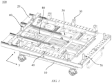
- a direction of an x-axis of a coordinate system in FIG. 1 is a first direction, and a direction of a y-axis is a second direction.
- first and second are merely used for distinguishing different objectives, and cannot be construed as indicating or implying relative importance or implicitly indicating the quantity, specific sequence or primary and secondary relations of technical features indicated.
- a plurality of' means two or more, unless expressly specified otherwise.
- term "and/or” is merely an association relation describing an associated object, and means that there can be three relations.
- a and/or B can represent: only A exists, both A and B exist, or only B exists.
- the character "j" herein generally indicates an "or" relation between associated objects.
- a connection may be a fixed connection, a detachable connection, or an integral connection; may be a mechanical connection or an electric connection; and may be a direct connection or an indirect connection by means of an intermediate medium, or may be communication between interiors of two elements or interaction between the two elements.
- traction batteries are used more and more widely.
- the traction batteries are not only used in energy storage power systems such as hydraulic power, thermal power, wind power and solar power stations, but also widely used in electric vehicles such as electric bicycles, electric motorcycles, electric vehicles, aerospace and other fields. With the continuous expansion of the application field of traction batteries, market demand for the traction batteries is also expanding.
- a semi-automatic apparatus is mainly used on a battery production line to process, assemble, transmit and detect batteries.
- battery components in a previous procedure are generally transferred to a next procedure by a transfer device and then are assembled.
- a first driving assembly of a positioning transmission mechanism is configured to drive a first locking assembly and a second locking assembly to move toward or away from each other in a first direction of a positioning platform, such that the first locking assembly and the second locking assembly cooperate to support and fix two ends of a piece-to-be-transferred in the first direction, so as to be compatible with pieces-to-be-transferred having different specifications and sizes. Therefore, during changeover, the transfer device is not required to be changed, as long as a distance between the first locking assembly and the second locking assembly is adjusted, such that production efficiency during changeover is effectively improved, and production costs are reduced.
- the transfer device 100 disclosed in an embodiment of the present application is not only suitable for transferring battery components in a battery production line, but also suitable for transferring parts in an automobile production line, a ship production line, etc.
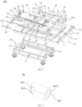
- FIG. 1 an assembled schematic diagram of a transfer device according to some embodiments of the present application is shown in FIG. 1 ; and an exploded schematic diagram of a transfer device according to some embodiments of the present application is shown in FIG. 2 .
- the present application provides a transfer device 100.
- the transfer device includes: an automated guided vehicle 10, a positioning platform 20 and a positioning transmission mechanism.
- the automated guided vehicle 10 is provided with a supporting frame 11; the positioning platform 20 is arranged on the supporting frame 11; and the positioning transmission mechanism includes a first locking assembly 30, a second locking assembly 40, and a first driving assembly 50 connected to the first locking assembly 30 and the second locking assembly 40, where the first locking assembly 30 and the second locking assembly 40 are arranged on two opposite sides of the positioning platform 20 at an interval in a first direction in a horizontal plane, and the first driving assembly 50 is configured to drive the first locking assembly and the second locking assembly to move toward or away from each other, such that the first locking assembly 30 and the second locking assembly 40 cooperate to fix a piece-to-be-transferred.
- the automated guided vehicle 10 is a transport vehicle equipped with an electromagnetic automated guided device, an optical automated guided device, etc., may travel along a specified guidance path, and has safety protection and various transfer functions.
- the first locking assembly and the second locking assembly are configured to cooperate to support and fix the piece-to-be-transferred.
- the first driving assembly 50 is configured to provide power when the first locking assembly and the second locking assembly move toward or away from each other.
- the first driving assembly 50 drives the first locking assembly 30 and the second locking assembly 40 to move toward or away from each other, such that by adjusting a distance between the first locking assembly 30 and the second locking assembly, the first locking assembly 30 and the second locking assembly cooperate to fix two ends of the piece-to-be-transferred in the first direction.
- space between the first locking assembly 30 and the second locking assembly 40 may be compatible with pieces-to-be-transferred having different specifications and sizes, and the transfer device 100 is not required to be changed during changeover. Therefore, production efficiency during changeover is effectively improved, and the transfer device is conducive to reduction in labor costs and production costs.
- the first driving assembly 50 includes a first driving member (not shown in figures) and a first transmission assembly connected to the first driving member, the first transmission assembly is connected to the first locking assembly 30 and the second locking assembly 40, and the first driving member is configured to drive the first transmission assembly to move, so as to drive the first locking assembly 30 and the second locking assembly 40 to move toward or away from each other.
- the first driving member is an electric motor
- the first transmission assembly is a ball screw structure
- the first transmission assembly includes a first lead screw 51, a first spiral transmission member 52 and a second spiral transmission member.
- the first lead screw 51 extends in the first direction and is connected to the first driving member, two ends of the first lead screw 51 are provided with a first thread and a second thread, respectively, and the first thread and the second thread are arranged in opposite directions.
- the first spiral transmission member 52 is in threaded connection to the first thread
- the second spiral transmission member is in threaded connection to the second thread
- the first spiral transmission member is connected to the first locking assembly 30
- the second spiral transmission member is connected to the second locking assembly 40
- the first lead screw 51 rotates, the first spiral transmission member 52 and the second spiral transmission member are adapted to move toward or away from each other along the first lead screw 51.
- first spiral transmission member 52 and the second spiral transmission member are in threaded connection to the first thread and the second thread, respectively, such that the first spiral transmission member 52, the second spiral transmission member and the first lead screw 51 form a ball screw structure. Since the first thread and the second thread are arranged in opposite directions, when the first lead screw 51 is driven by the first driving member to rotate, the first spiral transmission member 52 and the second spiral transmission member may move toward or away from each other along the first lead screw 51, so as to drive the first locking assembly 30 and the second locking assembly 40 to move toward or away from each other. Therefore, the distance between the first locking assembly 30 and the second locking assembly 40 may be adjusted, so as to be compatible with pieces-to-be-transferred having different specifications and sizes.
- the first transmission assembly includes a plurality of first lead screws 51, a first spiral transmission member 52 and a second spiral transmission member.
- the plurality of first lead screws 51 are connected to each other by means of a coupler 53, the two first lead screws 51 located on two ends of the positioning platform 20 in the first direction are provided with a first thread and a second thread, respectively, the first thread and the second thread are arranged in opposite directions, the first spiral transmission member 52 and the second spiral transmission member are in threaded connection to the first thread and the second thread, respectively, the first spiral transmission member 52 is connected to the first locking assembly 30, and the second spiral transmission member is connected to the second locking assembly 40.
- the first driving member drives one of the first lead screws 51 to rotate
- the first spiral transmission member 52 and the second spiral transmission member may drive the first locking assembly 30 and the second locking assembly 40 to move toward or away from each other.
- the first locking assembly 30 includes a first slide rail 31, a second slide rail 32, a first slide block 33, a second slide block 34, a first connecting plate 35 and at least one first positioning block 36.
- the first slide rail 31 and the second slide rail 32 are arranged on two sides of the first lead screw 51 and extend in the first direction.
- the first slide block 33 and the second slide block 34 are in sliding connection to the first slide rail 31 and the second slide rail 32, respectively.
- the first connecting plate 35 is connected to the first slide block 33, the second slide block 34 and the first spiral transmission member 52.
- the at least one first positioning block 36 is arranged on the first connecting plate 35, and a top of the first positioning block 36 is provided with a first supporting portion configured to clamp the piece-to-be-transferred.
- the second locking assembly 40 includes: a third slide rail 41 and a fourth slide rail 42, which are arranged on two sides of the first lead screw 51 and extend in the first direction; a third slide block and a fourth slide block, which are in sliding connection to the third slide rail 41 and the fourth slide rail 42, respectively; a second connecting plate 43, which is connected to the third slide block, the fourth slide block and the second spiral transmission member; and at least one second positioning block 44, which is arranged on the second connecting plate 43, where a top of the second positioning block 44 is provided with a second supporting portion, and the first supporting portion and the second supporting portion are configured to cooperate to fix the piece-to-be-transferred.
- One or more first positioning blocks 36 may be arranged.
- the plurality of first positioning blocks 36 are arranged on the first connecting plate 35 at intervals.
- One or more second positioning blocks 44 may be arranged.
- the plurality of second positioning blocks 44 are arranged on the second connecting plate 43 at intervals.
- the first supporting portion and the second supporting portion are configured to support one end of the piece-to-be-transferred in the first direction, and are configured to clamp the piece-to-be-transferred when the first positioning block 36 and the second positioning block 44 move toward each other, so as to ensure stability during transfer.
- the at least one first positioning block 36 is arranged on the first connecting plate 35, and the first connecting plate 35 is connected to the first spiral transmission member 52, a first slide block 33 and a second slide block 34 such that the first connecting plate 35 may be driven by the first spiral transmission member 52 to reciprocate in the first direction relative to the first slide rail 31 and the second slide rail 32, so as to drive the at least one first positioning block 36 to reciprocate in the first direction.
- the at least one second positioning block 44 is arranged on the second connecting plate 43, and the second connecting plate 43 is connected to the second spiral transmission member, a third slide block and a fourth slide block, such that the second connecting plate 43 may be driven by the second spiral transmission member to reciprocate in the first direction relative to the third slide rail 41 and the fourth slide rail 42, so as to drive the at least one first positioning block 36 to reciprocate in the first direction. Therefore, the distance between the first positioning block 36 and the second positioning assembly 44 is adjusted, so as to adapt to pieces-to-be-transferred of different specifications and sizes. Then, the first supporting portion and the second supporting portion on the first positioning block 36 and the second positioning block 44 support and fix the two ends of the piece-to-be-transferred in the first direction.
- the structure and principle are relatively simple, and implementation is easy.
- a plurality of first connecting portions are arranged on the first connecting plate 35 and the second connecting plate 43 at intervals, bottoms of the first positioning block 36 and the second positioning block 44 are provided with second connecting portions, and the first connecting portions are in detachable connection to the second connecting portions.
- the first connecting portions are in detachable connection to the second connecting portions, and a plurality of first connecting portions are arranged.
- each first positioning block 36 or second positioning block 44 may be selectively connected to one of the plurality of first connecting portions by means of the second connecting portion. Further, distances between the plurality of first positioning blocks 36 or the plurality of second positioning blocks 44 are adjusted, such that the first positioning blocks 36 and the second positioning block 44 may effectively support and fix pieces-to-be-transferred having different specifications and sizes, so as to ensure support and fixation reliability of the piece-to-be-transferred.
- one of the first connecting portion and the second connecting portion is a positioning recess 351
- the other one is a positioning column 361
- the positioning column 361 is inserted into the positioning recess 351.
- One of the first connecting portion and the second connecting portion is a positioning recess 351, and the other one is a positioning column 361. That is, the first connecting portion is a positioning recess 351, and the second connecting portion is a positioning column 361; or the first connecting portion is a positioning column 361, and the second connecting portion is a positioning recess 351.
- the positioning column 361 of the first positioning block 36 is inserted into the positioning recess 351 of the first connecting plate 35, such that the first positioning block 36 is connected to the first connecting plate 35.
- the positioning column 361 of the second positioning block 44 is inserted into the positioning recess 351 of the second connecting plate 43, such that the second positioning block 44 is connected to the second connecting plate 43, and assembly efficiency of a product is improved.
- FIG. 3 a schematic diagram of a positioning block according to some embodiments of the present application is shown in FIG. 3 .
- an outer surface of the positioning column 361 is provided with a snap-fit protrusion 3611
- an inner circumferential surface of the positioning recess 351 is provided with a snap-fit groove
- the snap-fit protrusion 3611 is in snap-fit with the snap-fit groove.
- a plurality of snap-fit protrusions 3611 are arranged, and the plurality of the snap-fit protrusions 3611 are arranged at intervals on an outer circumferential side of the positioning column 361.
- a plurality of snap-fit grooves are arranged, and the plurality of snap-fit grooves are provided at intervals along an inner circumferential surface of the positioning recess 351.
- the outer surface of the positioning column 361 is provided with the snap-fit protrusion 3611, and the inner circumferential surface of the positioning recess 351 is provided with the snap-fit groove.
- the snap-fit protrusion 3611 may be in snap-fit with the snap-fit groove, which is conducive to further improvement in connection reliability between the first positioning block 36 and the first connecting plate 35, and between the second positioning block 44 and the second connecting plate 43, and facilitates separation of the first positioning block 36 from the first connecting plate 35, and separation of the second positioning block 44 from the second connecting plate 43 under the action of an external force, thereby improving assembly and disassembly efficiency of a product.
- the first supporting portion includes a first step structure 362, and the first step structure 362 faces the second positioning block 44 and is provided with a first step surface 363 configured to support the piece-to-be-transferred.
- the second supporting portion includes a second step structure, and the second step structure faces the first positioning block 36 and is provided with a second step surface configured to support the piece-to-be-transferred.
- a top of the first positioning block 36 is partially recessed towards a side of the second positioning block 44 to form the first step structure 362, and a top of the second positioning block 44 is partially recessed towards a side of the first positioning block 36 to form the second step structure.
- the first step surface 363 and the second step surface are configured to support the piece-to-be-transferred at the same time, and when the first positioning block 36 and the second positioning block 44 to move toward each other, the first step structure 362 and the second step structure may cooperate to clamp the piece-to-be-transferred, so as to play a limiting role, thereby improving stability of the piece-to-be-transferred in a transfer process.
- two ends of the first connecting plate 35 and two ends of the second connecting plate 43 are all provided with first casters 352 and second casters 353, and the first casters 352 and the second casters 353 are in rolling connection to the positioning platform 20.
- the two ends of the first connecting plate 35 and the two ends of the second connecting plate 43 in the second direction are all provided with the first casters 352 and the second casters 353.
- the first casters 352 and the second casters 353 on the first connecting plate 35 are in rolling connection to the positioning platform 20, so as to play a role in supporting the first connecting plate 35, and avoid the situation that the first connecting plate 35 is inclined due to uneven stress, which is conducive to improvement in movement stability of the first connecting plate 35.
- the first casters 352 and the second casters 353 on the second connecting 43 are in rolling connection to the positioning platform 20, so as to play a role in supporting the second connecting plate 43, and avoid the situation that the second connecting plate 43 is inclined due to uneven stress, which is conducive to improvement in movement stability of the second connecting plate 43, and further conducive to improvement in stability of a piece-to-be-transferred in a transfer process.
- the positioning transmission mechanism further includes: a first limiting assembly 60, a second limiting assembly 70, and a second driving assembly 80 connected to the first limiting assembly 60.
- the first limiting assembly 60 and the second limiting assembly 70 are arranged on two opposite sides of the positioning platform 20 at an interval in the second direction in the horizontal plane, and the second driving assembly 80 is configured to drive the first limiting assembly 60 to move in a direction toward or away from the second limiting assembly 70, such that the first limiting assembly 60 and the second limiting assembly 70 cooperate to clamp the piece-to-be-transferred; and the second direction is perpendicular to the first direction.
- the first limiting assembly 60 and the second limiting assembly 70 are configured to fix two ends of the piece-to-be-transferred in the second direction, such that the piece-to-be-transferred is relatively fixed relative to the positioning platform 20 in the second direction.
- the first limiting assembly 60 and the second limiting assembly 70 may be driven by the second driving assembly 80 to clamp two ends of the piece-to-be-transferred in the second direction, so as to improve stability of the piece-to-be-transferred in a transfer process.
- the first limiting assembly 60 and the second limiting assembly 70 may be driven by the second driving assembly 80 to move toward or away from each other, so as to adjust a distance between the first limiting assembly 60 and the second limiting assembly 70 in the second direction, such that the first locking assembly 30 and the second locking assembly 40 cooperate to fix pieces-to-be-transferred having different specifications and sizes.
- the second driving assembly 80 includes a second driving member (not shown in figures) and a second transmission assembly connected to the second driving member, and the second transmission assembly is connected to the first limiting assembly 60.
- the second driving member is configured to drive the second transmission assembly to move, so as to drive the first limiting assembly 60 to move in the direction toward or away from the second limiting assembly 70.
- the second driving member is an electric motor
- the second transmission assembly is a ball screw structure
- first limiting assembly 60 is a movable assembly
- second limiting assembly 70 is a fixed assembly
- the second transmission assembly may be connected to the first limiting assembly 60 and the second limiting assembly 70, so as to drive the first limiting assembly 60 and the second limiting assembly 70 to move at the same time.
- the first transmission assembly may drive the first limiting assembly 60 to move in the direction toward or away from the second limiting assembly 70, such that the first limiting assembly and the second limiting assembly 70 cooperate to clamp two ends of the piece-to-be-transferred in the second direction.
- the second transmission assembly includes a second lead screw 81 and a third spiral transmission member 82 in threaded connection to the second lead screw 81.
- the second lead screw 81 extends in the second direction
- the third spiral transmission member 82 is connected to the first limiting assembly 60, and when the second driving member drives the second lead screw 81 to rotate, the third spiral transmission member 82 is adapted to reciprocate along the second lead screw 81, so as to drive the first limiting assembly 60 to move in the direction toward or away from the second limiting assembly 70.
- Two ends of the second lead screw 81 are in rotating connection to the positioning platform 20, the second lead screw 81 is perpendicular to the first lead screw 51, and the second lead screw 81 is arranged at a different height from the first lead screw 51.
- the third spiral transmission member 82 is connected to the first limiting assembly 60, when the second driving member drives the second lead screw 81 to rotate, the third spiral transmission member 82 may drive the first limiting assembly 60 to reciprocate in the second direction. Therefore, the distance between the first limiting assembly 60 and the second limiting assembly 70 may be adjusted, so as to fix pieces-to-be-transferred having different lengths in the second direction in an adjustable manner.
- the first limiting assembly 60 includes a fifth slide rail 61, a sixth slide rail 62, a fifth slide block 63, a sixth slide block 64, a third connecting plate 65 and at least one first limiting block 66.
- the fifth slide rail 61 and the sixth slide rail 62 are arranged on two sides of the second lead screw 81 and extend in the second direction.
- the fifth slide block 63 and the sixth slide block 64 are in sliding connection to the fifth slide rail 61 and the sixth slide rail 62, respectively.
- the third connecting plate 65 is connected to the fifth slide block 63, the sixth slide block 64 and the third spiral transmission member 82.
- the at least one first limiting block 66 is arranged on the third connecting plate 65, and is configured to abut against one end of the piece-to-be-transferred in the second direction.
- the second limiting assembly 70 includes a fourth connecting plate 71 and at least one second limiting block 72 arranged on the fourth connecting plate 71.
- the fourth connecting plate 71 is parallel to the third connecting plate 65, and the fourth connecting plate and the third connecting plate 65 are arranged on two ends of the positioning platform 20 at an interval.
- the at least one second limiting block 72 is configured to abut against the piece-to-be-transferred.
- the third connecting plate 65 is connected to the third spiral transmission member 82, the fifth slide block 63 and the sixth slide block 64 such that the third connecting plate may be driven by the third spiral transmission member 82 to reciprocate in the second direction relative to the fifth slide rail 61 and the sixth slide rail 62.
- the at least one first limiting block 66 is arranged on the third connecting plate 65, such that when the third connecting plate 65 moves in the second direction, the at least one first limiting block 66 may abut against one end of the piece-to-be-transferred in the second direction.
- the fourth connecting plate 71 and the third connecting plate 65 are arranged in parallel to each other at an interval, such that when the third spiral transmission member 82 drives the first limiting block 66 on the third connecting plate 65 to move, the first limiting block 66 and the second limiting block 72 may cooperate to abut against two ends of the piece-to-be-transferred in the second direction, so as to clamp the two ends of the piece-to-be-transferred in the second direction.
- a height of the first limiting block 66 and a height of the second limiting block 72 are greater than a height of the first step surface 363 and a height of the second step surface.
- the third connecting plate 65 and the fourth connecting plate 71 are further provided with a plurality of positioning recesses 351, the plurality of positioning recesses 351 on the third connecting plate 65 and the fourth connecting plate 71 are provided at intervals in the first direction, bottoms of the first limiting block 66 and the second limiting block 72 are provided with positioning columns 361, and the positioning columns 361 are inserted into the positioning recesses 351.
- the supporting frame 11 is provided with a positioning pin 111
- the positioning platform 20 is provided with a bearing guide sleeve 21 matching the positioning pin 111
- the positioning pin 111 is inserted into the bearing guide sleeve 21.
- the positioning pin 111 is inserted into the bearing guide sleeve 21 such that connection reliability between the positioning platform 20 and the supporting frame 11 can be improved. Moreover, a position of the positioning platform 20 relative to the supporting frame 11 is relatively fixed, which is conducive to improvement in stability of the piece-to-be-transferred in a transfer process.
- the transfer device 100 further includes a handlebar 22, which is arranged at one end of the positioning platform 20.
- the handlebar 22 is configured to be held by an operator such that the operator can conveniently push the transfer device 100 to move as required.
- the positioning platform 20 is further provided with a reference plate 73.
- the reference plate 73, the third connecting plate 65 and the fourth connecting plate 71 are parallel to each other at intervals, and the reference plate is configured to provide a positioning reference when a piece-to-be-transferred is fixed.
- the positioning platform 20 is provided with a first graduated scale and a second graduated scale.
- the first graduated scale extends from one end of the positioning platform 20 to the other end in the first direction, and is configured to measure a moving distance of the first locking assembly 30.
- the second graduated scale extends from one end of the positioning platform 20 to the other end in the second direction, and is configured to measure a distance of one end of the first limiting assembly 60.
- the present application provides a transfer device 100.
- the transfer device includes an automated guided vehicle 10, a positioning platform 20 and a positioning transmission mechanism.
- the automated guided vehicle 10 is provided with a supporting frame 11.
- the positioning platform 20 is arranged on the supporting frame 11.
- the positioning transmission mechanism includes a first locking assembly 30, a second locking assembly 40, a first limiting assembly 60, a second limiting assembly 70, a first driving assembly 50 connected to the first locking assembly 30 and the second locking assembly 40, and a second driving assembly 80 connected to the first limiting assembly 60.
- the first locking assembly 30 and the second locking assembly 40 are arranged on two opposite sides of the positioning platform 20 at an interval in a first direction in the horizontal plane, and the first limiting assembly 60 and the second limiting assembly 70 are arranged on two opposite sides of the positioning platform 20 at an interval in a second direction perpendicular to the first direction in the horizontal plane.
- the first driving assembly 50 is configured to drive the first locking assembly 30 and the second locking assembly 40 to move toward or away from each other, such that the first locking assembly 30 and the second locking assembly 40 cooperate to lock two ends of the piece-to-be-transferred in the first direction.
- the second driving assembly 80 is configured to drive the first limiting assembly 60 to move toward or away from the second limiting assembly 70, such that the first limiting assembly 60 and the second limiting assembly 70 cooperate to lock two ends of the second limiting assembly 70.
- the distance between the first locking assembly 30 and the second locking assembly 40, and the distance between the first limiting assembly 60 and the second limiting assembly 70 may be adjusted, so as to be compatible with pieces-to-be-transferred having different specifications and sizes. Therefore, the transfer device 100 is not required to be changed during changeover, so as to improve production efficiency during changeover.
Landscapes
- Engineering & Computer Science (AREA)
- Transportation (AREA)
- Mechanical Engineering (AREA)
- Chemical & Material Sciences (AREA)
- Combustion & Propulsion (AREA)
- Transmission Devices (AREA)
- Automatic Assembly (AREA)
Abstract
Description
- The present application claims the benefit of priority to
Chinese patent application no. 202320153750.7, filed on January 28, 2023 - The present application relates to the technical field of transfer apparatuses, and particularly relates to a transfer device.
- This part provides merely background information related to the present disclosure, which is not necessarily the prior art.
- At present, a semi-automatic apparatus is mainly used on a battery production line to process, assemble, transmit and detect batteries. In the related art, on the battery production line, battery components in a previous procedure are transferred to a next procedure by a transfer device and then are assembled. However, as each transfer device is only suitable for battery components with the same specifications and dimensions and cannot automatically adapt to products of different sizes, it is required to manually change the transfer device for changeover of products, resulting in low production efficiency.
- An objective of the present application is to provide a transfer device, which is configured to automatically adapt to pieces-to-be-transferred having different specifications and sizes, and is conducive to improvement in production efficiency during changeover.
- The present application provides a transfer device. The transfer device includes: an automated guided vehicle, which is provided with a supporting frame; a positioning platform, which is arranged on the supporting frame; and a positioning transmission mechanism, which includes a first locking assembly, a second locking assembly, and a first driving assembly connected to the first locking assembly and the second locking assembly, where the first locking assembly and the second locking assembly are arranged on two opposite sides of the positioning platform at an interval in a first direction in a horizontal plane, and the first driving assembly is configured to drive the first locking assembly and the second locking assembly to move toward or away from each other, such that the first locking assembly and the second locking assembly cooperate to fix a piece-to-be-transferred.
- According to the transfer device provided in the present application, the automated guided vehicle may drive the positioning transmission mechanism to move along a preset route, and may carry the piece-to-be-transferred according to production and assembly procedures, which is conducive to reduction in labor cost, and improvement in assembly efficiency of a product. The first locking assembly and the second locking assembly may cooperate to fix the piece-to-be-transferred, and the first driving assembly drives the first locking assembly and the second locking assembly to move toward or away from each other, such that by adjusting a distance between the first locking assembly and the second locking assembly, space between the first locking assembly and the second locking assembly may be compatible with pieces-to-be-transferred having different specifications and sizes, and the transfer device is not required to be changed during changeover. Therefore, production efficiency during changeover is effectively improved, and the transfer device is conducive to reduction in labor costs and production costs.
- In addition, the transfer device provided in the present application can further have additional technical features as follows:
In some implementations of the present application, the first driving assembly includes: a first driving member; and a first transmission assembly, which is connected to the first driving member and is connected to the first locking assembly and the second locking assembly, respectively, where the first driving member is configured to drive the first transmission assembly to move, so as to drive the first locking assembly and the second locking assembly to move toward or away from each other. - In the implementation, the first driving assembly includes the first driving member, and the first transmission member, which is connected to the first driving member, and the first transmission member is connected to the first locking assembly and the second locking assembly. In this way, when the first driving member drives the first transmission member to execute an action, the first locking assembly and the second locking assembly may be driven to move toward or away from each other, so as to fix pieces-to-be-transferred having different specifications and sizes in a compatible manner.
- In some implementations of the present application, the first transmission assembly includes: a first lead screw, which is connected to the first driving member, where the first lead screw extends in the first direction, two ends of the first lead screw are provided with a first thread and a second thread, respectively, and the first thread and the second thread are arranged in opposite directions; and a first spiral transmission member and a second spiral transmission member, where the first spiral transmission member is in threaded connection to the first thread, the second spiral transmission member is in threaded connection to the second thread, the first spiral transmission member is connected to the first locking assembly, the second spiral transmission member is connected to the second locking assembly, and when the first lead screw rotates, the first spiral transmission member and the second spiral transmission member are adapted to move toward or away from each other along the first lead screw.
- In the implementation, the first spiral transmission member and the second spiral transmission member are in threaded connection to the first thread and the second thread, respectively, such that the first spiral transmission member, the second spiral transmission member and the first lead screw form the ball screw structure. Since the first thread and the second thread are arranged in opposite directions, when the first lead screw is driven by the first driving member to rotate, the first spiral transmission member and the second spiral transmission member may move toward or away from each other along the first lead screw, so as to drive the first locking assembly and the second locking assembly to move toward or away from each other. Therefore, the distance between the first locking assembly and the second locking assembly may be adjusted, so as to be compatible with pieces-to-be-transferred having different specifications and sizes.
- In some implementations of the present application, the first locking assembly includes: a first slide rail and a second slide rail, which are arranged on two sides of the first lead screw and extend in the first direction; a first slide block and a second slide block, which are in sliding connection to the first slide rail and the second slide rail, respectively; a first connecting plate, which is connected to the first slide block, the second slide block and the first spiral transmission member; and at least one first positioning block, which is arranged on the first connecting plate, where a top of the first positioning block is provided with a first supporting portion configured to clamp the piece-to-be-transferred.
- In the implementation, the at least one first positioning block is arranged on the first connecting plate, the first connecting plate is connected to the first slide block and the second slide block, and may be driven by the first spiral transmission member to reciprocate in the first direction relative to the first slide rail and the second slide rail, so as to drive the at least one first positioning block to reciprocate in the first direction, and further to adjust the distance between the first positioning block and the second locking assembly. The structure and principle are relatively simple, and implementation is easy.
- In some implementations of the present application, the second locking assembly includes: a third slide rail and a fourth slide rail, which are arranged on two sides of the first lead screw and extend in the first direction; a third slide block and a fourth slide block, which are in sliding connection to the third slide rail and the fourth slide rail, respectively; a second connecting plate, which is connected to the third slide block, the fourth slide block and the second spiral transmission member; and at least one second positioning block, which is arranged on the second connecting plate, where a top of the second positioning block is provided with a second supporting portion, and the first supporting portion and the second supporting portion are configured to cooperate to fix the piece-to-be-transferred.
- In the implementation, the at least one second positioning block is arranged on the second connecting plate, and the second connecting plate is connected to the third slide block and the fourth slide block, and may be driven by the second spiral transmission member to reciprocate in the first direction relative to the third slide rail and the fourth slide rail, so as to drive the at least one second positioning block to reciprocate in the first direction. Further, the second supporting portion on the second positioning block and the first supporting portion on the first positioning block may cooperate to fix the piece-to-be-transferred.
- In some implementations of the present application, in a second direction perpendicular to the first direction in the horizontal plane, a plurality of first connecting portions are arranged on the first connecting plate and the second connecting plate at intervals, bottoms of the first positioning block and the second positioning block are provided with second connecting portions, and the first connecting portions are in detachable connection to the second connecting portions.
- In the implementation, the plurality of first connecting portions are arranged on the first connecting plate and the second connecting plate, the plurality of first connecting portions are arranged at intervals in the second direction perpendicular to the first direction, and the first positioning block and the second positioning block are in detachable connection to the first connecting portions by means of the second connecting portions, such that in the case of a plurality of first positioning blocks and second positioning blocks, each first positioning block or second positioning block may be selectively connected to one of the plurality of first connecting portions by means of the second connecting portion. Further, distances between the plurality of first positioning blocks or the plurality of second positioning blocks may be adjusted, so as to fix pieces-to-be-transferred having different specifications and sizes in a compatible manner.
- In some implementations of the present application, one of the first connecting portion and the second connecting portion is a positioning recess, the other one is a positioning column, and the positioning column is inserted into the positioning recess.
- In the implementation, one of the first connecting portion and the second connecting portion is a positioning recess, and the other one is a positioning column. That is, the first connecting portion is a positioning recess, and the second connecting portion is a positioning column; or the first connecting portion is a positioning column, and the second connecting portion is a positioning recess. The positioning column is inserted into the positioning recess, such that the first positioning block is connected to the first connecting plate, and the second positioning block is connected to the second connecting plate.
- In some implementations of the present application, an outer surface of the positioning column is provided with a snap-fit protrusion, an inner circumferential surface of the positioning recess is provided with a snap-fit groove, and when the positioning column is inserted into the positioning recess, the snap-fit protrusion is in snap-fit with the snap-fit groove.
- In the implementation, the outer surface of the positioning column is provided with the snap-fit protrusion, and the inner circumferential surface of the positioning recess is provided with the snap-fit recess. In this way, when the positioning column is inserted into the positioning recess, the snap-fit protrusion may be in snap-fit with the snap-fit groove, which is conducive to further improvement in connection reliability between the first positioning block and the first connecting plate, and between the second positioning block and the second connecting plate, and facilitates separation of the first positioning block from the first connecting plate, and separation of the second positioning block from the second connecting plate under the action of an external force, thereby improving assembly and disassembly efficiency of a product.
- In some implementations of the present application, the first supporting portion includes a first step structure, and the first step structure faces the second positioning block and is provided with a first step surface configured to support the piece-to-be-transferred; and the second supporting portion includes a second step structure, and the second step structure faces the first positioning block and is provided with a second step surface configured to support the piece-to-be-transferred.
- In the implementation, the first step surface and the second step surface are configured to support the piece-to-be-transferred at the same time, and the first step structure and the second step structure may clamp the piece-to-be-transferred when moving toward each other, so as to play a limiting role, thereby improving stability of the piece-to-be-transferred in a transfer process.
- In some implementations of the present application, two ends of the first connecting plate and two ends of the second connecting plate are all provided with first casters and second casters, and the first casters and the second casters are in rolling connection to the positioning platform.
- In the implementation, the two ends of the first connecting plate and the two ends of the second connecting plate are provided with the first casters and the second casters. In this way, when the first connecting plate is driven by the first spiral transmission member to reciprocate, the first casters and the second casters are in rolling connection to the positioning platform, so as to play a role in supporting the first connecting plate, and avoid the situation that the first connecting plate is inclined due to uneven stress, which is conducive to improvement in movement stability of the first connecting plate, and further conducive to improvement in stability of a piece-to-be-transferred in a transfer process.
- In some implementations of the present application, the positioning transmission mechanism further includes: a first limiting assembly, a second limiting assembly, and a second driving assembly connected to the first limiting assembly, where the first limiting assembly and the second limiting assembly are arranged on two opposite sides of the positioning platform at an interval in the second direction in the horizontal plane, and the second driving assembly is configured to drive the first limiting assembly to move in a direction toward or away from the second limiting assembly, such that the first limiting assembly and the second limiting assembly cooperate to clamp the piece-to-be-transferred; and the second direction is perpendicular to the first direction.
- In the implementation, after the first locking assembly and the second locking assembly fix two ends of the piece-to-be-transferred in the first direction, the first limiting assembly and the second limiting assembly may be driven by the second driving assembly to clamp two ends of the piece-to-be-transferred in the second direction, so as to improve stability of the piece-to-be-transferred in a transfer process. In addition, the first limiting assembly and the second limiting assembly may be driven by the second driving assembly to move toward or away from each other, so as to adjust a distance between the first limiting assembly and the second limiting assembly in the second direction, such that the first locking assembly and the second locking assembly cooperate to fix and then transfer pieces-to-be-transferred having different specifications and sizes.
- In some implementations of the present application, the second driving assembly includes: a second driving member; and a second transmission assembly, which is connected to the second driving member and the first limiting assembly, where the second driving member is configured to drive the second transmission assembly to move, so as to drive the first limiting assembly to move in the direction toward or away from the second limiting assembly.
- In the implementation, the first limiting assembly is a movable assembly, and the second limiting assembly is a fixed assembly. When the second driving member drives the second transmission assembly to move, the first transmission assembly may drive the first limiting assembly to move in the direction toward or away from the second limiting assembly, such that the first limiting assembly and the second limiting assembly cooperate to clamp two ends of the piece-to-be-transferred in the second direction.
- In some implementations of the present application, the second transmission assembly includes: a second lead screw, which extends in the second direction; and a third spiral transmission member, which is in threaded connection to the second lead screw, and is connected to the first limiting assembly, where when the second driving member drives the second lead screw to rotate, the third spiral transmission member is adapted to reciprocate along the second lead screw, so as to drive the first limiting assembly to move in the direction toward or away from the second limiting assembly.
- In the implementation, the second transmission assembly includes the second lead screw and the third spiral transmission member, the third spiral transmission member is in threaded connection to the second lead screw, and the third spiral transmission member and the second lead screw form a ball screw structure. In this way, since the third spiral transmission member is connected to the first limiting assembly, when the second driving member drives the second lead screw to rotate, the third spiral transmission member may drive the first limiting assembly to reciprocate in the second direction. Therefore, the distance between the first limiting assembly and the second limiting assembly may be adjusted, so as to match pieces-to-be-transferred having different lengths in the second direction.
- In some implementations of the present application, the first limiting assembly includes: a fifth slide rail and a sixth slide rail, which are arranged on two sides of the second lead screw and extend in the second direction; a fifth slide block and a sixth slide block, which are in sliding connection to the fifth slide rail and the sixth slide rail, respectively; a third connecting plate, which is connected to the fifth slide block, the sixth slide block and the third spiral transmission member; and at least one first limiting block, which is arranged on the third connecting plate, and is configured to abut against the piece-to-be-transferred.
- In the implementation, the third connecting plate is connected to the third spiral transmission member, the fifth slide block and the sixth slide block such that the third connecting plate may be driven by the third spiral transmission member to reciprocate in the second direction relative to the fifth slide rail and the sixth slide rail. The at least one first limiting block is arranged on the third connecting plate, such that when the third connecting plate moves in the second direction, the at least one first limiting block abuts against one end of the to-be-transported member in the second direction, and the at least one first limiting block and the second limiting assembly clamp the piece-to-be-transferred in a matching manner.
- In some implementations of the present application, the second limiting assembly includes: a fourth connecting plate, which is parallel to the third connecting plate, where the fourth connecting plate and the third connecting plate are arranged on the positioning platform at an interval; and at least one second limiting block, which is arranged on the fourth connecting plate, and is configured to abut against the piece-to-be-transferred.
- In the implementation, the second limiting assembly includes the fourth connecting plate and the at least one second limiting block, the fourth connecting plate is parallel to the third connecting plate, and the fourth connecting plate and the third connecting plate are arranged at an interval. In this way, when the third spiral transmission member drives the first limiting block on the third connecting plate to move, the first limiting block and the second limiting block may cooperate to abut against two ends of the piece-to-be-transferred in the second direction, so as to clamp the two ends of the piece-to-be-transferred in the second direction.
- In some implementations of the present application, the supporting frame is provided with a positioning pin, the positioning platform is provided with a bearing guide sleeve matching the positioning pin, and the positioning pin is inserted into the bearing guide sleeve.
- In the implementation, when the positioning platform is arranged on the supporting frame, the positioning pin is inserted into the bearing guide sleeve such that connection reliability between the positioning platform and the supporting frame can be improved, the situation that the positioning platform moves relative to the supporting frame is improved, which is conducive to improvement in stability of the piece-to-be-transferred in a transfer process.
- In some implementations of the present application, the transfer device further includes: a handlebar, which is arranged at one end of the positioning platform.
- In the implementation, the handlebar is configured to be held by an operator such that the operator can conveniently push the transfer device to move as required.
- Various other advantages and benefits will become apparent to those of ordinary skill in the art upon reading the following detailed description of preferred implementations. Accompanying drawings are merely for the purpose of illustrating preferred implementations, and are not to be construed as limiting the present application. Moreover, the same reference numerals represent the same components throughout the accompanying drawings. In the accompanying drawings:
-
FIG. 1 is an assembled schematic diagram of a transfer device according to some embodiments of the present application; -
FIG. 2 is an exploded schematic diagram of a transfer device according to some embodiments of the present application; and -
FIG. 3 is a perspective schematic diagram of a first positioning column from an angle of view according to some embodiments of the present application. -
-
transfer device 100; - automated guided
vehicle 10,positioning platform 20, first lockingassembly 30, second lockingassembly 40, first drivingassembly 50, first limitingassembly 60, second limitingassembly 70, and second drivingassembly 80; - supporting
frame 11, bearingguide sleeve 21,handlebar 22,first slide rail 31,second slide rail 32,first slide block 33,second slide block 34, first connectingplate 35,first positioning block 36,third slide rail 41,fourth slide rail 42, second connectingplate 43,second positioning block 44,first lead screw 51, firstspiral transmission member 52,coupler 53,fifth slide rail 61,sixth slide rail 62,fifth slide block 63,sixth slide block 64, third connectingplate 65, first limitingblock 66, fourth connectingplate 71, second limitingblock 72,reference plate 73,second lead screw 81, and thirdspiral transmission member 82; -
positioning pin 111,positioning recess 351,first caster 352,second caster 353,positioning column 361,first step structure 362, andfirst step surface 363; and - snap-
fit protrusion 3611. - A direction of an x-axis of a coordinate system in
FIG. 1 is a first direction, and a direction of a y-axis is a second direction. - Implementations of technical solutions of the present application will be described in detail in combination with accompanying drawings. The following implementations are merely used for illustrating technical solutions of the present application more clearly, and therefore merely serve as examples rather than limiting the scope of protection of the present application.
- Unless otherwise defined, all technical and scientific terms used herein have the same meanings as those commonly understood by those skilled in the art to which the present application belongs. Terms used herein are merely for the purpose of describing particular implementations, but are not intended to limit the present application. Terms "include", "comprise", "have" and their any variations in the description and claims of the present application as well as the above brief description of accompanying drawings are intended to cover non-exclusive inclusions.
- In the description of implementations of the present application, terms "first" and "second" are merely used for distinguishing different objectives, and cannot be construed as indicating or implying relative importance or implicitly indicating the quantity, specific sequence or primary and secondary relations of technical features indicated. In the description of implementations of the present application, "a plurality of' means two or more, unless expressly specified otherwise.
- Reference to an "implementation" herein means that a specific feature, structure or characteristic described in combination with an implementation can be included in at least one implementation of the present application. Appearance of this phrase in all positions in the description does not necessarily mean the same implementation, nor is an independent or alternative implementation mutually exclusive with other implementations. Those skilled in the art explicitly and implicitly understand that implementations described herein can be combined with other implementations.
- In the description of implementations of the present application, term "and/or" is merely an association relation describing an associated object, and means that there can be three relations. For example, A and/or B can represent: only A exists, both A and B exist, or only B exists. In addition, the character "j" herein generally indicates an "or" relation between associated objects.
- In the description of implementations of the present application, term "a plurality of' refers to two or more (including two). Similarly, "a plurality of groups" refers to two or more groups (including two groups), and "a plurality of pieces" refers to two or more pieces (including two pieces).
- In the description of implementations of the present application, orientation or position relations indicated by terms "center", "longitudinal", "transverse", "length", "width", "thickness", "upper", "lower", "front", "rear", "left", "right", "vertical", "horizontal", "top", "bottom", "inner", "outer", "clockwise", "anticlockwise", "axial", "radial", "circumferential", etc. are based on orientation or position relations shown in accompanying drawings, and are merely for convenience of description of implementations of the present application and simplification of the description, rather than indicating or implying that a device or element referred to must have a specific orientation or be constructed and operated in a described orientation, and therefore cannot be construed as limiting the present application.
- In the description of implementations of the present application, unless otherwise explicitly specified and defined, terms "mount", "connected", "connect", "fix", etc. should be interpreted in the broad sense. For example, a connection may be a fixed connection, a detachable connection, or an integral connection; may be a mechanical connection or an electric connection; and may be a direct connection or an indirect connection by means of an intermediate medium, or may be communication between interiors of two elements or interaction between the two elements. Those of ordinary skills in the art can understand specific meanings of the above terms in implementations of the present application according to specific circumstances.
- At present, from the perspective of the development of the market situation, traction batteries are used more and more widely. The traction batteries are not only used in energy storage power systems such as hydraulic power, thermal power, wind power and solar power stations, but also widely used in electric vehicles such as electric bicycles, electric motorcycles, electric vehicles, aerospace and other fields. With the continuous expansion of the application field of traction batteries, market demand for the traction batteries is also expanding.
- In the related art, a semi-automatic apparatus is mainly used on a battery production line to process, assemble, transmit and detect batteries. On the battery production line, battery components in a previous procedure are generally transferred to a next procedure by a transfer device and then are assembled.
- Inventors of the present application note that since each transfer device in a battery production line is only suitable for battery components with the same specification and dimension, and cannot automatically adapt to products with different sizes, during changeover, it is required to manually change the transfer device, resulting in relatively low production efficiency, and relatively high cost.
- In order to solve the problems that during changeover, the transfer device is required to be manually changed, resulting in relatively low production efficiency, and relatively high costs, inventors of the present application designs a transfer device after in-depth research. A first driving assembly of a positioning transmission mechanism is configured to drive a first locking assembly and a second locking assembly to move toward or away from each other in a first direction of a positioning platform, such that the first locking assembly and the second locking assembly cooperate to support and fix two ends of a piece-to-be-transferred in the first direction, so as to be compatible with pieces-to-be-transferred having different specifications and sizes. Therefore, during changeover, the transfer device is not required to be changed, as long as a distance between the first locking assembly and the second locking assembly is adjusted, such that production efficiency during changeover is effectively improved, and production costs are reduced.
- The
transfer device 100 disclosed in an embodiment of the present application is not only suitable for transferring battery components in a battery production line, but also suitable for transferring parts in an automobile production line, a ship production line, etc. - In the following embodiments, for convenience of description, a transfer device for a battery production line in an embodiment of the present application is described.
- With reference to
FIGs. 1 and2 , an assembled schematic diagram of a transfer device according to some embodiments of the present application is shown inFIG. 1 ; and an exploded schematic diagram of a transfer device according to some embodiments of the present application is shown inFIG. 2 . According to some embodiments of the present application, the present application provides atransfer device 100. The transfer device includes: an automated guidedvehicle 10, apositioning platform 20 and a positioning transmission mechanism. The automated guidedvehicle 10 is provided with a supportingframe 11; thepositioning platform 20 is arranged on the supportingframe 11; and the positioning transmission mechanism includes afirst locking assembly 30, asecond locking assembly 40, and afirst driving assembly 50 connected to thefirst locking assembly 30 and thesecond locking assembly 40, where thefirst locking assembly 30 and thesecond locking assembly 40 are arranged on two opposite sides of thepositioning platform 20 at an interval in a first direction in a horizontal plane, and the first drivingassembly 50 is configured to drive the first locking assembly and the second locking assembly to move toward or away from each other, such that thefirst locking assembly 30 and thesecond locking assembly 40 cooperate to fix a piece-to-be-transferred. - The automated guided
vehicle 10 is a transport vehicle equipped with an electromagnetic automated guided device, an optical automated guided device, etc., may travel along a specified guidance path, and has safety protection and various transfer functions. The first locking assembly and the second locking assembly are configured to cooperate to support and fix the piece-to-be-transferred. Thefirst driving assembly 50 is configured to provide power when the first locking assembly and the second locking assembly move toward or away from each other. - The
first driving assembly 50 drives thefirst locking assembly 30 and thesecond locking assembly 40 to move toward or away from each other, such that by adjusting a distance between thefirst locking assembly 30 and the second locking assembly, thefirst locking assembly 30 and the second locking assembly cooperate to fix two ends of the piece-to-be-transferred in the first direction. Further, space between thefirst locking assembly 30 and thesecond locking assembly 40 may be compatible with pieces-to-be-transferred having different specifications and sizes, and thetransfer device 100 is not required to be changed during changeover. Therefore, production efficiency during changeover is effectively improved, and the transfer device is conducive to reduction in labor costs and production costs. - According to some embodiments of the present application, the first driving
assembly 50 includes a first driving member (not shown in figures) and a first transmission assembly connected to the first driving member, the first transmission assembly is connected to thefirst locking assembly 30 and thesecond locking assembly 40, and the first driving member is configured to drive the first transmission assembly to move, so as to drive thefirst locking assembly 30 and thesecond locking assembly 40 to move toward or away from each other. - As an example, the first driving member is an electric motor, and the first transmission assembly is a ball screw structure.
- Specifically, the first transmission assembly includes a
first lead screw 51, a firstspiral transmission member 52 and a second spiral transmission member. Thefirst lead screw 51 extends in the first direction and is connected to the first driving member, two ends of thefirst lead screw 51 are provided with a first thread and a second thread, respectively, and the first thread and the second thread are arranged in opposite directions. The firstspiral transmission member 52 is in threaded connection to the first thread, the second spiral transmission member is in threaded connection to the second thread, the first spiral transmission member is connected to thefirst locking assembly 30, the second spiral transmission member is connected to thesecond locking assembly 40, and when thefirst lead screw 51 rotates, the firstspiral transmission member 52 and the second spiral transmission member are adapted to move toward or away from each other along thefirst lead screw 51. - Two ends of the
first thread 51 are in rotating connection to thepositioning platform 20, and the firstspiral transmission member 52 and the second spiral transmission member are in threaded connection to the first thread and the second thread, respectively, such that the firstspiral transmission member 52, the second spiral transmission member and thefirst lead screw 51 form a ball screw structure. Since the first thread and the second thread are arranged in opposite directions, when thefirst lead screw 51 is driven by the first driving member to rotate, the firstspiral transmission member 52 and the second spiral transmission member may move toward or away from each other along thefirst lead screw 51, so as to drive thefirst locking assembly 30 and thesecond locking assembly 40 to move toward or away from each other. Therefore, the distance between thefirst locking assembly 30 and thesecond locking assembly 40 may be adjusted, so as to be compatible with pieces-to-be-transferred having different specifications and sizes. - With reference to
FIGs. 1 and2 , according to an embodiment of the present application, the first transmission assembly includes a plurality of first lead screws 51, a firstspiral transmission member 52 and a second spiral transmission member. The plurality of first lead screws 51 are connected to each other by means of acoupler 53, the two first lead screws 51 located on two ends of thepositioning platform 20 in the first direction are provided with a first thread and a second thread, respectively, the first thread and the second thread are arranged in opposite directions, the firstspiral transmission member 52 and the second spiral transmission member are in threaded connection to the first thread and the second thread, respectively, the firstspiral transmission member 52 is connected to thefirst locking assembly 30, and the second spiral transmission member is connected to thesecond locking assembly 40. When the first driving member drives one of the first lead screws 51 to rotate, the firstspiral transmission member 52 and the second spiral transmission member may drive thefirst locking assembly 30 and thesecond locking assembly 40 to move toward or away from each other. - With reference to
FIGs. 1 and2 , according to some embodiments of the present application, thefirst locking assembly 30 includes afirst slide rail 31, asecond slide rail 32, afirst slide block 33, asecond slide block 34, a first connectingplate 35 and at least onefirst positioning block 36. Thefirst slide rail 31 and thesecond slide rail 32 are arranged on two sides of thefirst lead screw 51 and extend in the first direction. Thefirst slide block 33 and thesecond slide block 34 are in sliding connection to thefirst slide rail 31 and thesecond slide rail 32, respectively. The first connectingplate 35 is connected to thefirst slide block 33, thesecond slide block 34 and the firstspiral transmission member 52. The at least onefirst positioning block 36 is arranged on the first connectingplate 35, and a top of thefirst positioning block 36 is provided with a first supporting portion configured to clamp the piece-to-be-transferred. - With reference to
FIGs. 1 and2 , according to some embodiments of the present application, thesecond locking assembly 40 includes: athird slide rail 41 and afourth slide rail 42, which are arranged on two sides of thefirst lead screw 51 and extend in the first direction; a third slide block and a fourth slide block, which are in sliding connection to thethird slide rail 41 and thefourth slide rail 42, respectively; a second connectingplate 43, which is connected to the third slide block, the fourth slide block and the second spiral transmission member; and at least onesecond positioning block 44, which is arranged on the second connectingplate 43, where a top of thesecond positioning block 44 is provided with a second supporting portion, and the first supporting portion and the second supporting portion are configured to cooperate to fix the piece-to-be-transferred. - One or more first positioning blocks 36 may be arranged. In the case of a plurality of first positioning blocks 36, the plurality of first positioning blocks 36 are arranged on the first connecting
plate 35 at intervals. - One or more second positioning blocks 44 may be arranged. In the case of a plurality of the second positioning blocks 44, the plurality of second positioning blocks 44 are arranged on the second connecting
plate 43 at intervals. - The first supporting portion and the second supporting portion are configured to support one end of the piece-to-be-transferred in the first direction, and are configured to clamp the piece-to-be-transferred when the
first positioning block 36 and thesecond positioning block 44 move toward each other, so as to ensure stability during transfer. - The at least one
first positioning block 36 is arranged on the first connectingplate 35, and the first connectingplate 35 is connected to the firstspiral transmission member 52, afirst slide block 33 and asecond slide block 34 such that the first connectingplate 35 may be driven by the firstspiral transmission member 52 to reciprocate in the first direction relative to thefirst slide rail 31 and thesecond slide rail 32, so as to drive the at least onefirst positioning block 36 to reciprocate in the first direction. - Similarly, the at least one
second positioning block 44 is arranged on the second connectingplate 43, and the second connectingplate 43 is connected to the second spiral transmission member, a third slide block and a fourth slide block, such that the second connectingplate 43 may be driven by the second spiral transmission member to reciprocate in the first direction relative to thethird slide rail 41 and thefourth slide rail 42, so as to drive the at least onefirst positioning block 36 to reciprocate in the first direction. Therefore, the distance between thefirst positioning block 36 and thesecond positioning assembly 44 is adjusted, so as to adapt to pieces-to-be-transferred of different specifications and sizes. Then, the first supporting portion and the second supporting portion on thefirst positioning block 36 and thesecond positioning block 44 support and fix the two ends of the piece-to-be-transferred in the first direction. The structure and principle are relatively simple, and implementation is easy. - With reference to
FIGs. 1 and2 , according to some embodiments of the present application, in a second direction perpendicular to the first direction in the horizontal plane, a plurality of first connecting portions are arranged on the first connectingplate 35 and the second connectingplate 43 at intervals, bottoms of thefirst positioning block 36 and thesecond positioning block 44 are provided with second connecting portions, and the first connecting portions are in detachable connection to the second connecting portions. - The first connecting portions are in detachable connection to the second connecting portions, and a plurality of first connecting portions are arranged. In the case of a plurality of first positioning blocks 36 and second positioning blocks 44, each
first positioning block 36 orsecond positioning block 44 may be selectively connected to one of the plurality of first connecting portions by means of the second connecting portion. Further, distances between the plurality of first positioning blocks 36 or the plurality of second positioning blocks 44 are adjusted, such that the first positioning blocks 36 and thesecond positioning block 44 may effectively support and fix pieces-to-be-transferred having different specifications and sizes, so as to ensure support and fixation reliability of the piece-to-be-transferred. - With reference to
FIGs. 1 and2 , according to some embodiments of the present application, one of the first connecting portion and the second connecting portion is apositioning recess 351, the other one is apositioning column 361, and thepositioning column 361 is inserted into thepositioning recess 351. - One of the first connecting portion and the second connecting portion is a
positioning recess 351, and the other one is apositioning column 361. That is, the first connecting portion is apositioning recess 351, and the second connecting portion is apositioning column 361; or the first connecting portion is apositioning column 361, and the second connecting portion is apositioning recess 351. - When the
first positioning block 36 is assembled with the first connectingplate 35, thepositioning column 361 of thefirst positioning block 36 is inserted into thepositioning recess 351 of the first connectingplate 35, such that thefirst positioning block 36 is connected to the first connectingplate 35. When thesecond positioning block 44 is assembled with the second connectingplate 43, thepositioning column 361 of thesecond positioning block 44 is inserted into thepositioning recess 351 of the second connectingplate 43, such that thesecond positioning block 44 is connected to the second connectingplate 43, and assembly efficiency of a product is improved. - With reference to
FIG. 3 , a schematic diagram of a positioning block according to some embodiments of the present application is shown inFIG. 3 . According to some embodiments of the present application, an outer surface of thepositioning column 361 is provided with a snap-fit protrusion 3611, an inner circumferential surface of thepositioning recess 351 is provided with a snap-fit groove, and when thepositioning column 361 is inserted into thepositioning recess 351, the snap-fit protrusion 3611 is in snap-fit with the snap-fit groove. - As an example, a plurality of snap-
fit protrusions 3611 are arranged, and the plurality of the snap-fit protrusions 3611 are arranged at intervals on an outer circumferential side of thepositioning column 361. A plurality of snap-fit grooves are arranged, and the plurality of snap-fit grooves are provided at intervals along an inner circumferential surface of thepositioning recess 351. - The outer surface of the
positioning column 361 is provided with the snap-fit protrusion 3611, and the inner circumferential surface of thepositioning recess 351 is provided with the snap-fit groove. In this way, when thepositioning column 361 is inserted into thepositioning recess 351, the snap-fit protrusion 3611 may be in snap-fit with the snap-fit groove, which is conducive to further improvement in connection reliability between thefirst positioning block 36 and the first connectingplate 35, and between thesecond positioning block 44 and the second connectingplate 43, and facilitates separation of thefirst positioning block 36 from the first connectingplate 35, and separation of thesecond positioning block 44 from the second connectingplate 43 under the action of an external force, thereby improving assembly and disassembly efficiency of a product. - With reference to
FIGs. 1-3 , according to some embodiments of the present application, the first supporting portion includes afirst step structure 362, and thefirst step structure 362 faces thesecond positioning block 44 and is provided with afirst step surface 363 configured to support the piece-to-be-transferred. The second supporting portion includes a second step structure, and the second step structure faces thefirst positioning block 36 and is provided with a second step surface configured to support the piece-to-be-transferred. - A top of the
first positioning block 36 is partially recessed towards a side of thesecond positioning block 44 to form thefirst step structure 362, and a top of thesecond positioning block 44 is partially recessed towards a side of thefirst positioning block 36 to form the second step structure. - The
first step surface 363 and the second step surface are configured to support the piece-to-be-transferred at the same time, and when thefirst positioning block 36 and thesecond positioning block 44 to move toward each other, thefirst step structure 362 and the second step structure may cooperate to clamp the piece-to-be-transferred, so as to play a limiting role, thereby improving stability of the piece-to-be-transferred in a transfer process. - With reference to
FIGs. 1 and2 , according to some embodiments of the present application, two ends of the first connectingplate 35 and two ends of the second connectingplate 43 are all provided withfirst casters 352 andsecond casters 353, and thefirst casters 352 and thesecond casters 353 are in rolling connection to thepositioning platform 20. - The two ends of the first connecting
plate 35 and the two ends of the second connectingplate 43 in the second direction are all provided with thefirst casters 352 and thesecond casters 353. In this way, when the first connectingplate 35 is driven by the firstspiral transmission member 52 to reciprocate, thefirst casters 352 and thesecond casters 353 on the first connectingplate 35 are in rolling connection to thepositioning platform 20, so as to play a role in supporting the first connectingplate 35, and avoid the situation that the first connectingplate 35 is inclined due to uneven stress, which is conducive to improvement in movement stability of the first connectingplate 35. Similarly, when the second connectingplate 43 is driven by the second spiral transmission member to reciprocate, thefirst casters 352 and thesecond casters 353 on the second connecting 43 are in rolling connection to thepositioning platform 20, so as to play a role in supporting the second connectingplate 43, and avoid the situation that the second connectingplate 43 is inclined due to uneven stress, which is conducive to improvement in movement stability of the second connectingplate 43, and further conducive to improvement in stability of a piece-to-be-transferred in a transfer process. - With reference to
FIGs. 1 and2 , according to some embodiments of the present application, the positioning transmission mechanism further includes: a first limitingassembly 60, a second limitingassembly 70, and asecond driving assembly 80 connected to the first limitingassembly 60. The first limitingassembly 60 and the second limitingassembly 70 are arranged on two opposite sides of thepositioning platform 20 at an interval in the second direction in the horizontal plane, and thesecond driving assembly 80 is configured to drive the first limitingassembly 60 to move in a direction toward or away from the second limitingassembly 70, such that the first limitingassembly 60 and the second limitingassembly 70 cooperate to clamp the piece-to-be-transferred; and the second direction is perpendicular to the first direction. - The first limiting
assembly 60 and the second limitingassembly 70 are configured to fix two ends of the piece-to-be-transferred in the second direction, such that the piece-to-be-transferred is relatively fixed relative to thepositioning platform 20 in the second direction. - After the
first locking assembly 30 and thesecond locking assembly 40 fix two ends of the piece-to-be-transferred in the first direction in the horizontal plane, the first limitingassembly 60 and the second limitingassembly 70 may be driven by thesecond driving assembly 80 to clamp two ends of the piece-to-be-transferred in the second direction, so as to improve stability of the piece-to-be-transferred in a transfer process. In addition, the first limitingassembly 60 and the second limitingassembly 70 may be driven by thesecond driving assembly 80 to move toward or away from each other, so as to adjust a distance between the first limitingassembly 60 and the second limitingassembly 70 in the second direction, such that thefirst locking assembly 30 and thesecond locking assembly 40 cooperate to fix pieces-to-be-transferred having different specifications and sizes. - According to some embodiments of the present application, the
second driving assembly 80 includes a second driving member (not shown in figures) and a second transmission assembly connected to the second driving member, and the second transmission assembly is connected to the first limitingassembly 60. The second driving member is configured to drive the second transmission assembly to move, so as to drive the first limitingassembly 60 to move in the direction toward or away from the second limitingassembly 70. - As an example, the second driving member is an electric motor, and the second transmission assembly is a ball screw structure.
- It can be understood that the first limiting
assembly 60 is a movable assembly, and the second limitingassembly 70 is a fixed assembly. Certainly, the second transmission assembly may be connected to the first limitingassembly 60 and the second limitingassembly 70, so as to drive the first limitingassembly 60 and the second limitingassembly 70 to move at the same time. - When the second driving member drives the second transmission assembly to move, the first transmission assembly may drive the first limiting
assembly 60 to move in the direction toward or away from the second limitingassembly 70, such that the first limiting assembly and the second limitingassembly 70 cooperate to clamp two ends of the piece-to-be-transferred in the second direction. - With reference to
FIGs. 1 and2 , according to some embodiments of the present application, the second transmission assembly includes asecond lead screw 81 and a thirdspiral transmission member 82 in threaded connection to thesecond lead screw 81. Thesecond lead screw 81 extends in the second direction, the thirdspiral transmission member 82 is connected to the first limitingassembly 60, and when the second driving member drives thesecond lead screw 81 to rotate, the thirdspiral transmission member 82 is adapted to reciprocate along thesecond lead screw 81, so as to drive the first limitingassembly 60 to move in the direction toward or away from the second limitingassembly 70. - Two ends of the
second lead screw 81 are in rotating connection to thepositioning platform 20, thesecond lead screw 81 is perpendicular to thefirst lead screw 51, and thesecond lead screw 81 is arranged at a different height from thefirst lead screw 51. - Since the third
spiral transmission member 82 is connected to the first limitingassembly 60, when the second driving member drives thesecond lead screw 81 to rotate, the thirdspiral transmission member 82 may drive the first limitingassembly 60 to reciprocate in the second direction. Therefore, the distance between the first limitingassembly 60 and the second limitingassembly 70 may be adjusted, so as to fix pieces-to-be-transferred having different lengths in the second direction in an adjustable manner. - With reference to
FIGs. 1 and2 , according to some embodiments of the present application, the first limitingassembly 60 includes afifth slide rail 61, asixth slide rail 62, afifth slide block 63, asixth slide block 64, a third connectingplate 65 and at least one first limitingblock 66. Thefifth slide rail 61 and thesixth slide rail 62 are arranged on two sides of thesecond lead screw 81 and extend in the second direction. Thefifth slide block 63 and thesixth slide block 64 are in sliding connection to thefifth slide rail 61 and thesixth slide rail 62, respectively. The third connectingplate 65 is connected to thefifth slide block 63, thesixth slide block 64 and the thirdspiral transmission member 82. The at least one first limitingblock 66 is arranged on the third connectingplate 65, and is configured to abut against one end of the piece-to-be-transferred in the second direction. - With reference to
FIGs. 1 and2 , according to some embodiments of the present application, the second limitingassembly 70 includes a fourth connectingplate 71 and at least one second limitingblock 72 arranged on the fourth connectingplate 71. The fourth connectingplate 71 is parallel to the third connectingplate 65, and the fourth connecting plate and the third connectingplate 65 are arranged on two ends of thepositioning platform 20 at an interval. The at least one second limitingblock 72 is configured to abut against the piece-to-be-transferred. - The third connecting
plate 65 is connected to the thirdspiral transmission member 82, thefifth slide block 63 and thesixth slide block 64 such that the third connecting plate may be driven by the thirdspiral transmission member 82 to reciprocate in the second direction relative to thefifth slide rail 61 and thesixth slide rail 62. The at least one first limitingblock 66 is arranged on the third connectingplate 65, such that when the third connectingplate 65 moves in the second direction, the at least one first limitingblock 66 may abut against one end of the piece-to-be-transferred in the second direction. - The fourth connecting
plate 71 and the third connectingplate 65 are arranged in parallel to each other at an interval, such that when the thirdspiral transmission member 82 drives the first limitingblock 66 on the third connectingplate 65 to move, the first limitingblock 66 and the second limitingblock 72 may cooperate to abut against two ends of the piece-to-be-transferred in the second direction, so as to clamp the two ends of the piece-to-be-transferred in the second direction. - It can be understood that a height of the first limiting
block 66 and a height of the second limitingblock 72 are greater than a height of thefirst step surface 363 and a height of the second step surface. - Specifically, the third connecting
plate 65 and the fourth connectingplate 71 are further provided with a plurality of positioning recesses 351, the plurality of positioning recesses 351 on the third connectingplate 65 and the fourth connectingplate 71 are provided at intervals in the first direction, bottoms of the first limitingblock 66 and the second limitingblock 72 are provided withpositioning columns 361, and thepositioning columns 361 are inserted into the positioning recesses 351. - With reference to
FIGs. 1 and2 , according to some embodiments of the present application, the supportingframe 11 is provided with apositioning pin 111, thepositioning platform 20 is provided with abearing guide sleeve 21 matching thepositioning pin 111, and thepositioning pin 111 is inserted into thebearing guide sleeve 21. - When the
positioning platform 20 is arranged on the supportingframe 11, thepositioning pin 111 is inserted into thebearing guide sleeve 21 such that connection reliability between thepositioning platform 20 and the supportingframe 11 can be improved. Moreover, a position of thepositioning platform 20 relative to the supportingframe 11 is relatively fixed, which is conducive to improvement in stability of the piece-to-be-transferred in a transfer process. - With reference to
FIGs. 1 and2 , according to some embodiments of the present application, thetransfer device 100 further includes ahandlebar 22, which is arranged at one end of thepositioning platform 20. - The
handlebar 22 is configured to be held by an operator such that the operator can conveniently push thetransfer device 100 to move as required. - With reference to
FIGs. 1 and2 , according to some embodiments of the present application, thepositioning platform 20 is further provided with areference plate 73. Thereference plate 73, the third connectingplate 65 and the fourth connectingplate 71 are parallel to each other at intervals, and the reference plate is configured to provide a positioning reference when a piece-to-be-transferred is fixed. - According to some embodiments of the present application, the
positioning platform 20 is provided with a first graduated scale and a second graduated scale. The first graduated scale extends from one end of thepositioning platform 20 to the other end in the first direction, and is configured to measure a moving distance of thefirst locking assembly 30. The second graduated scale extends from one end of thepositioning platform 20 to the other end in the second direction, and is configured to measure a distance of one end of the first limitingassembly 60. - With reference to
FIGs. 1 and2 , according to some embodiments of the present application, the present application provides atransfer device 100. The transfer device includes an automated guidedvehicle 10, apositioning platform 20 and a positioning transmission mechanism. The automated guidedvehicle 10 is provided with a supportingframe 11. Thepositioning platform 20 is arranged on the supportingframe 11. The positioning transmission mechanism includes afirst locking assembly 30, asecond locking assembly 40, a first limitingassembly 60, a second limitingassembly 70, afirst driving assembly 50 connected to thefirst locking assembly 30 and thesecond locking assembly 40, and asecond driving assembly 80 connected to the first limitingassembly 60. Thefirst locking assembly 30 and thesecond locking assembly 40 are arranged on two opposite sides of thepositioning platform 20 at an interval in a first direction in the horizontal plane, and the first limitingassembly 60 and the second limitingassembly 70 are arranged on two opposite sides of thepositioning platform 20 at an interval in a second direction perpendicular to the first direction in the horizontal plane. Thefirst driving assembly 50 is configured to drive thefirst locking assembly 30 and thesecond locking assembly 40 to move toward or away from each other, such that thefirst locking assembly 30 and thesecond locking assembly 40 cooperate to lock two ends of the piece-to-be-transferred in the first direction. Thesecond driving assembly 80 is configured to drive the first limitingassembly 60 to move toward or away from the second limitingassembly 70, such that the first limitingassembly 60 and the second limitingassembly 70 cooperate to lock two ends of the second limitingassembly 70. The distance between thefirst locking assembly 30 and thesecond locking assembly 40, and the distance between the first limitingassembly 60 and the second limitingassembly 70 may be adjusted, so as to be compatible with pieces-to-be-transferred having different specifications and sizes. Therefore, thetransfer device 100 is not required to be changed during changeover, so as to improve production efficiency during changeover. - What are described above are merely optimal embodiments of the present application, and are not intended to limit the scope of protection of the present application. Any changes or substitutions that can readily occur to those skilled in the art within the scope of technology disclosed in the present application should all fall within the scope of protection of the present application. Therefore, the scope of protection of the present application shall be subject to the scope of protection of the claims.
Claims (17)
- A transfer device, comprising:an automated guided vehicle, which is provided with a supporting frame;a positioning platform, which is arranged on the supporting frame; anda positioning transmission mechanism, which comprises a first locking assembly, a second locking assembly, and a first driving assembly connected to the first locking assembly and the second locking assembly, wherein the first locking assembly and the second locking assembly are arranged on two opposite sides of the positioning platform at an interval in a first direction in a horizontal plane, and the first driving assembly is configured to drive the first locking assembly and the second locking assembly to move toward or away from each other, such that the first locking assembly and the second locking assembly cooperate to fix a piece-to-be-transferred.
- The transfer device according to claim 1, wherein the first driving assembly comprises:a first driving member; anda first transmission assembly, which is connected to the first driving member and is connected to the first locking assembly and the second locking assembly, respectively, wherein the first driving member is configured to drive the first transmission assembly to move, so as to drive the first locking assembly and the second locking assembly to move toward or away from each other.
- The transfer device according to claim 2, wherein the first transmission assembly comprises:a first lead screw, which is connected to the first driving member, wherein the first lead screw extends in the first direction, two ends of the first lead screw are provided with a first thread and a second thread, respectively, and the first thread and the second thread are arranged in opposite directions; anda first spiral transmission member and a second spiral transmission member, wherein the first spiral transmission member is in threaded connection to the first thread, the second spiral transmission member is in threaded connection to the second thread, the first spiral transmission member is connected to the first locking assembly, the second spiral transmission member is connected to the second locking assembly, and when the first lead screw rotates, the first spiral transmission member and the second spiral transmission member are adapted to move toward or away from each other along the first lead screw.
- The transfer device according to claim 3, wherein the first locking assembly comprises:a first slide rail and a second slide rail, which are arranged on two sides of the first lead screw and extend in the first direction;a first slide block and a second slide block, which are in sliding connection to the first slide rail and the second slide rail, respectively;a first connecting plate, which is connected to the first slide block, the second slide block and the first spiral transmission member; andat least one first positioning block, which is arranged on the first connecting plate, wherein a top of the first positioning block is provided with a first supporting portion configured to clamp the piece-to-be-transferred.
- The transfer device according to claim 4, wherein the second locking assembly comprises:a third slide rail and a fourth slide rail, which are arranged on two sides of the first lead screw and extend in the first direction;a third slide block and a fourth slide block, which are in sliding connection to the third slide rail and the fourth slide rail, respectively;a second connecting plate, which is connected to the third slide block, the fourth slide block and the second spiral transmission member; andat least one second positioning block, which is arranged on the second connecting plate, wherein a top of the second positioning block is provided with a second supporting portion, and the first supporting portion and the second supporting portion are configured to cooperate to fix the piece-to-be-transferred.
- The transfer device according to claim 5, wherein in a second direction perpendicular to the first direction in the horizontal plane, a plurality of first connecting portions are arranged on the first connecting plate and the second connecting plate at intervals, bottoms of the first positioning block and the second positioning block are provided with second connecting portions, and the first connecting portions are in detachable connection to the second connecting portions.
- The transfer device according to claim 6, wherein one of the first connecting portion and the second connecting portion is a positioning recess, the other one is a positioning column, and the positioning column is inserted into the positioning recess.
- The transfer device according to claim 7, wherein an outer surface of the positioning column is provided with a snap-fit protrusion, an inner circumferential surface of the positioning recess is provided with a snap-fit groove, and when the positioning column is inserted into the positioning recess, the snap-fit protrusion is in snap-fit with the snap-fit groove.
- The transfer device according to any one of claims 5-8, wherein the first supporting portion comprises a first step structure, and the first step structure faces the second positioning block and is provided with a first step surface configured to support the piece-to-be-transferred; and
the second supporting portion comprises a second step structure, and the second step structure faces the first positioning block and is provided with a second step surface configured to support the piece-to-be-transferred. - The transfer device according to any one of claims 5-9, wherein two ends of the first connecting plate and two ends of the second connecting plate are all provided with first casters and second casters, and the first casters and the second casters are in rolling connection to the positioning platform.
- The transfer device according to any one of claims 1-10, wherein the positioning transmission mechanism further comprises: a first limiting assembly, a second limiting assembly, and a second driving assembly connected to the first limiting assembly, wherein the first limiting assembly and the second limiting assembly are arranged on two opposite sides of the positioning platform at an interval in a second direction in the horizontal plane, and the second driving assembly is configured to drive the first limiting assembly to move in a direction toward or away from the second limiting assembly, such that the first limiting assembly and the second limiting assembly cooperate to clamp the piece-to-be-transferred; and
the second direction is perpendicular to the first direction. - The transfer device according to claim 11, wherein the second driving assembly comprises:a second driving member; anda second transmission assembly, which is connected to the second driving member and the first limiting assembly, wherein the second driving member is configured to drive the second transmission assembly to move, so as to drive the first limiting assembly to move in the direction toward or away from the second limiting assembly.
- The transfer device according to claim 12, wherein the second transmission assembly comprises:a second lead screw, which extends in the second direction; anda third spiral transmission member, which is in threaded connection to the second lead screw, and is connected to the first limiting assembly, wherein when the second driving member drives the second lead screw to rotate, the third spiral transmission member is adapted to reciprocate along the second lead screw, so as to drive the first limiting assembly to move in the direction toward or away from the second limiting assembly.
- The transfer device according to claim 13, wherein the first limiting assembly comprises:a fifth slide rail and a sixth slide rail, which are arranged on two sides of the second lead screw and extend in the second direction;a fifth slide block and a sixth slide block, which are in sliding connection to the fifth slide rail and the sixth slide rail, respectively;a third connecting plate, which is connected to the fifth slide block, the sixth slide block and the third spiral transmission member; andat least one first limiting block, which is arranged on the third connecting plate, and is configured to abut against the piece-to-be-transferred.
- The transfer device according to claim 14, wherein the second limiting assembly comprises:a fourth connecting plate, which is parallel to the third connecting plate, wherein the fourth connecting plate and the third connecting plate are arranged on the positioning platform at an interval; andat least one second limiting block, which is arranged on the fourth connecting plate, and is configured to abut against the piece-to-be-transferred.
- The transfer device according to any one of claims 1-15, wherein the supporting frame is provided with a positioning pin, the positioning platform is provided with a bearing guide sleeve matching the positioning pin, and the positioning pin is inserted into the bearing guide sleeve.
- The transfer device according to any one of claims 1-16, further comprising: a handlebar, which is arranged at one end of the positioning platform.
Applications Claiming Priority (2)
| Application Number | Priority Date | Filing Date | Title |
|---|---|---|---|
| CN202320153750.7U CN219584048U (en) | 2023-01-28 | 2023-01-28 | Transfer device |
| PCT/CN2023/096539 WO2024156168A1 (en) | 2023-01-28 | 2023-05-26 | Transfer device |
Publications (4)
| Publication Number | Publication Date |
|---|---|
| EP4438406A1 true EP4438406A1 (en) | 2024-10-02 |
| EP4438406A4 EP4438406A4 (en) | 2025-01-01 |
| EP4438406B1 EP4438406B1 (en) | 2026-04-15 |
| EP4438406C0 EP4438406C0 (en) | 2026-04-15 |
Family
ID=87692618
Family Applications (1)
| Application Number | Title | Priority Date | Filing Date |
|---|---|---|---|
| EP23828662.9A Active EP4438406B1 (en) | 2023-01-28 | 2023-05-26 | Transfer device |
Country Status (4)
| Country | Link |
|---|---|
| EP (1) | EP4438406B1 (en) |
| CN (1) | CN219584048U (en) |
| ES (1) | ES3071819T3 (en) |
| WO (1) | WO2024156168A1 (en) |
Families Citing this family (2)
| Publication number | Priority date | Publication date | Assignee | Title |
|---|---|---|---|---|
| CN117021125B (en) * | 2023-10-10 | 2024-02-06 | 宁德时代新能源科技股份有限公司 | A matching control method and system |
| CN120024512B (en) * | 2025-03-24 | 2026-07-21 | 哈尔滨工业大学 | Space storage transfer platform with screw drive wedge pushes down |
Family Cites Families (7)
| Publication number | Priority date | Publication date | Assignee | Title |
|---|---|---|---|---|
| CN107323990B (en) * | 2017-08-28 | 2019-08-13 | 大连佳峰自动化股份有限公司 | A kind of wafer box transport vehicle and its wafer cassette automatic positioning mechanism |
| CN110937390A (en) * | 2019-11-11 | 2020-03-31 | 天奇自动化工程股份有限公司 | Battery moves and carries manipulator |
| CN211107141U (en) * | 2019-12-24 | 2020-07-28 | 郑州中智辉昂智能科技有限公司 | AGV intelligent vehicle |
| CN111959370B (en) * | 2020-08-06 | 2022-03-15 | 奇精机械股份有限公司 | Intelligent transport vehicle is used in machine part production |
| CN214420584U (en) * | 2021-03-05 | 2021-10-19 | 浙江同济科技职业学院 | AGV dolly of liftable material frame |
| CN112794072B (en) * | 2021-04-02 | 2021-06-25 | 苏州维嘉科技股份有限公司 | Material loading conveying equipment |
| CN113581324A (en) * | 2021-08-24 | 2021-11-02 | 成渝钒钛科技有限公司 | Transfer device for iron standard steel cooling equipment and use method thereof |
-
2023
- 2023-01-28 CN CN202320153750.7U patent/CN219584048U/en active Active
- 2023-05-26 EP EP23828662.9A patent/EP4438406B1/en active Active
- 2023-05-26 ES ES23828662T patent/ES3071819T3/en active Active
- 2023-05-26 WO PCT/CN2023/096539 patent/WO2024156168A1/en not_active Ceased
Also Published As
| Publication number | Publication date |
|---|---|
| CN219584048U (en) | 2023-08-25 |
| WO2024156168A1 (en) | 2024-08-02 |
| EP4438406B1 (en) | 2026-04-15 |
| EP4438406A4 (en) | 2025-01-01 |
| ES3071819T3 (en) | 2026-06-25 |
| EP4438406C0 (en) | 2026-04-15 |
Similar Documents
| Publication | Publication Date | Title |
|---|---|---|
| US20240253679A1 (en) | Transfer device | |
| EP4438406B1 (en) | Transfer device | |
| CN112720411A (en) | Traveling mechanism of rail-hanging inspection robot | |
| CN115285878A (en) | Trade frame integral type lifting device, year car platform and trade power station of electric vehicle | |
| CN103063435A (en) | Motor test platform | |
| CN216966583U (en) | Bridge plate cutting and positioning device | |
| EP4316999B1 (en) | Adjusting device, packaging apparatus and adjusting method | |
| CN215973346U (en) | Adjustable conveying platform and cargo separation layer frame | |
| CN214723591U (en) | Radar seeker subassembly decomposes frock | |
| CN210024280U (en) | Vehicle body centering device and vehicle body production line | |
| CN216946028U (en) | Frame integrated lifting device for battery replacing vehicle, vehicle carrying platform and battery replacing station | |
| CN220816272U (en) | Lengthened linear slide rail capable of being spliced with high precision | |
| CN218879215U (en) | High-precision mechanical synchronous walking heavy-load transmission mechanism | |
| CN109532897B (en) | Combined rail flat car | |
| CN213730686U (en) | Support suitable for angle steel automatic production line | |
| CN215244444U (en) | Electric power system cooling device of unmanned automobile | |
| CN224116136U (en) | A multi-type coupler assembly trolley | |
| CN215567306U (en) | Self-aligning roller bearing convenient to maintain | |
| CN212221332U (en) | Trolley traction fixer with increased contact surface | |
| CN113371099B (en) | Split type intelligent conveying trolley | |
| CN223237638U (en) | Limiter and bogie provided with same | |
| CN223394486U (en) | Climbing type submerged arc welding trolley | |
| CN216507973U (en) | Agv charging device for trolley | |
| CN221954376U (en) | Anti-collision device for AGV trolley | |
| CN223342338U (en) | Explosion-proof clamp AGV |
Legal Events
| Date | Code | Title | Description |
|---|---|---|---|
| STAA | Information on the status of an ep patent application or granted ep patent |
Free format text: STATUS: UNKNOWN |
|
| STAA | Information on the status of an ep patent application or granted ep patent |
Free format text: STATUS: THE INTERNATIONAL PUBLICATION HAS BEEN MADE |
|
| PUAI | Public reference made under article 153(3) epc to a published international application that has entered the european phase |
Free format text: ORIGINAL CODE: 0009012 |
|
| STAA | Information on the status of an ep patent application or granted ep patent |
Free format text: STATUS: REQUEST FOR EXAMINATION WAS MADE |
|
| 17P | Request for examination filed |
Effective date: 20240104 |
|
| AK | Designated contracting states |
Kind code of ref document: A1 Designated state(s): AL AT BE BG CH CY CZ DE DK EE ES FI FR GB GR HR HU IE IS IT LI LT LU LV MC ME MK MT NL NO PL PT RO RS SE SI SK SM TR |
|
| A4 | Supplementary search report drawn up and despatched |
Effective date: 20241129 |
|
| RIC1 | Information provided on ipc code assigned before grant |
Ipc: B62D 63/02 20060101ALI20241125BHEP Ipc: B60P 9/00 20060101ALI20241125BHEP Ipc: B60P 7/08 20060101AFI20241125BHEP |
|
| GRAP | Despatch of communication of intention to grant a patent |
Free format text: ORIGINAL CODE: EPIDOSNIGR1 |
|
| STAA | Information on the status of an ep patent application or granted ep patent |
Free format text: STATUS: GRANT OF PATENT IS INTENDED |
|
| INTG | Intention to grant announced |
Effective date: 20251212 |
|
| GRAS | Grant fee paid |
Free format text: ORIGINAL CODE: EPIDOSNIGR3 |
|
| GRAA | (expected) grant |
Free format text: ORIGINAL CODE: 0009210 |
|
| STAA | Information on the status of an ep patent application or granted ep patent |
Free format text: STATUS: THE PATENT HAS BEEN GRANTED |
|
| DAV | Request for validation of the european patent (deleted) | ||
| DAX | Request for extension of the european patent (deleted) | ||
| AK | Designated contracting states |
Kind code of ref document: B1 Designated state(s): AL AT BE BG CH CY CZ DE DK EE ES FI FR GB GR HR HU IE IS IT LI LT LU LV MC ME MK MT NL NO PL PT RO RS SE SI SK SM TR |
|
| REG | Reference to a national code |
Ref country code: CH Ref legal event code: F10 Free format text: ST27 STATUS EVENT CODE: U-0-0-F10-F00 (AS PROVIDED BY THE NATIONAL OFFICE) Effective date: 20260415 |
|
| REG | Reference to a national code |
Ref country code: DE Ref legal event code: R096 Ref document number: 602023015475 Country of ref document: DE |
|
| REG | Reference to a national code |
Ref country code: IE Ref legal event code: FG4D |
|
| U01 | Request for unitary effect filed |
Effective date: 20260428 |
|
| U07 | Unitary effect registered |
Designated state(s): AT BE BG DE DK EE FI FR IT LT LU LV MT NL PT RO SE SI Effective date: 20260508 |
|
| REG | Reference to a national code |
Ref country code: ES Ref legal event code: FG2A Ref document number: 3071819 Country of ref document: ES Kind code of ref document: T3 Effective date: 20260625 |
|
| U20 | Renewal fee for the european patent with unitary effect paid |
Year of fee payment: 4 Effective date: 20260526 |
|
| PGFP | Annual fee paid to national office [announced via postgrant information from national office to epo] |
Ref country code: ES Payment date: 20260601 Year of fee payment: 4 |