EP4438388A1 - Charging inlet - Google Patents
Charging inlet Download PDFInfo
- Publication number
- EP4438388A1 EP4438388A1 EP24158950.6A EP24158950A EP4438388A1 EP 4438388 A1 EP4438388 A1 EP 4438388A1 EP 24158950 A EP24158950 A EP 24158950A EP 4438388 A1 EP4438388 A1 EP 4438388A1
- Authority
- EP
- European Patent Office
- Prior art keywords
- charging
- inlet
- cover
- cover member
- heater
- Prior art date
- Legal status (The legal status is an assumption and is not a legal conclusion. Google has not performed a legal analysis and makes no representation as to the accuracy of the status listed.)
- Pending
Links
Images


Classifications
-
- B—PERFORMING OPERATIONS; TRANSPORTING
- B62—LAND VEHICLES FOR TRAVELLING OTHERWISE THAN ON RAILS
- B62D—MOTOR VEHICLES; TRAILERS
- B62D25/00—Superstructure or monocoque structure sub-units; Parts or details thereof not otherwise provided for
- B62D25/24—Superstructure sub-units with access or drainage openings having movable or removable closures; Sealing means therefor
-
- H—ELECTRICITY
- H01—ELECTRIC ELEMENTS
- H01R—ELECTRICALLY-CONDUCTIVE CONNECTIONS; STRUCTURAL ASSOCIATIONS OF A PLURALITY OF MUTUALLY-INSULATED ELECTRICAL CONNECTING ELEMENTS; COUPLING DEVICES; CURRENT COLLECTORS
- H01R13/00—Details of coupling devices of the kinds covered by groups H01R12/70 or H01R24/00 - H01R33/00
- H01R13/66—Structural association with built-in electrical component
- H01R13/665—Structural association with built-in electrical component with built-in electronic circuit
-
- B—PERFORMING OPERATIONS; TRANSPORTING
- B60—VEHICLES IN GENERAL
- B60L—PROPULSION OF ELECTRICALLY-PROPELLED VEHICLES; SUPPLYING ELECTRIC POWER FOR AUXILIARY EQUIPMENT OF ELECTRICALLY-PROPELLED VEHICLES; ELECTRODYNAMIC BRAKE SYSTEMS FOR VEHICLES IN GENERAL; MAGNETIC SUSPENSION OR LEVITATION FOR VEHICLES; MONITORING OPERATING VARIABLES OF ELECTRICALLY-PROPELLED VEHICLES; ELECTRIC SAFETY DEVICES FOR ELECTRICALLY-PROPELLED VEHICLES
- B60L50/00—Electric propulsion with power supplied within the vehicle
- B60L50/50—Electric propulsion with power supplied within the vehicle using propulsion power supplied by batteries or fuel cells
- B60L50/60—Electric propulsion with power supplied within the vehicle using propulsion power supplied by batteries or fuel cells using power supplied by batteries
-
- B—PERFORMING OPERATIONS; TRANSPORTING
- B60—VEHICLES IN GENERAL
- B60L—PROPULSION OF ELECTRICALLY-PROPELLED VEHICLES; SUPPLYING ELECTRIC POWER FOR AUXILIARY EQUIPMENT OF ELECTRICALLY-PROPELLED VEHICLES; ELECTRODYNAMIC BRAKE SYSTEMS FOR VEHICLES IN GENERAL; MAGNETIC SUSPENSION OR LEVITATION FOR VEHICLES; MONITORING OPERATING VARIABLES OF ELECTRICALLY-PROPELLED VEHICLES; ELECTRIC SAFETY DEVICES FOR ELECTRICALLY-PROPELLED VEHICLES
- B60L53/00—Methods of charging batteries, specially adapted for electric vehicles; Charging stations or on-board charging equipment therefor; Exchange of energy storage elements in electric vehicles
- B60L53/10—Methods of charging batteries, specially adapted for electric vehicles; Charging stations or on-board charging equipment therefor; Exchange of energy storage elements in electric vehicles characterised by the energy transfer between the charging station and the vehicle
- B60L53/14—Conductive energy transfer
- B60L53/16—Connectors, e.g. plugs or sockets, specially adapted for charging electric vehicles
-
- B—PERFORMING OPERATIONS; TRANSPORTING
- B60—VEHICLES IN GENERAL
- B60L—PROPULSION OF ELECTRICALLY-PROPELLED VEHICLES; SUPPLYING ELECTRIC POWER FOR AUXILIARY EQUIPMENT OF ELECTRICALLY-PROPELLED VEHICLES; ELECTRODYNAMIC BRAKE SYSTEMS FOR VEHICLES IN GENERAL; MAGNETIC SUSPENSION OR LEVITATION FOR VEHICLES; MONITORING OPERATING VARIABLES OF ELECTRICALLY-PROPELLED VEHICLES; ELECTRIC SAFETY DEVICES FOR ELECTRICALLY-PROPELLED VEHICLES
- B60L53/00—Methods of charging batteries, specially adapted for electric vehicles; Charging stations or on-board charging equipment therefor; Exchange of energy storage elements in electric vehicles
- B60L53/10—Methods of charging batteries, specially adapted for electric vehicles; Charging stations or on-board charging equipment therefor; Exchange of energy storage elements in electric vehicles characterised by the energy transfer between the charging station and the vehicle
- B60L53/14—Conductive energy transfer
- B60L53/18—Cables specially adapted for charging electric vehicles
-
- B—PERFORMING OPERATIONS; TRANSPORTING
- B60—VEHICLES IN GENERAL
- B60L—PROPULSION OF ELECTRICALLY-PROPELLED VEHICLES; SUPPLYING ELECTRIC POWER FOR AUXILIARY EQUIPMENT OF ELECTRICALLY-PROPELLED VEHICLES; ELECTRODYNAMIC BRAKE SYSTEMS FOR VEHICLES IN GENERAL; MAGNETIC SUSPENSION OR LEVITATION FOR VEHICLES; MONITORING OPERATING VARIABLES OF ELECTRICALLY-PROPELLED VEHICLES; ELECTRIC SAFETY DEVICES FOR ELECTRICALLY-PROPELLED VEHICLES
- B60L53/00—Methods of charging batteries, specially adapted for electric vehicles; Charging stations or on-board charging equipment therefor; Exchange of energy storage elements in electric vehicles
- B60L53/30—Constructional details of charging stations
- B60L53/35—Means for automatic or assisted adjustment of the relative position of charging devices and vehicles
-
- E—FIXED CONSTRUCTIONS
- E05—LOCKS; KEYS; WINDOW OR DOOR FITTINGS; SAFES
- E05F—DEVICES FOR MOVING WINGS INTO OPEN OR CLOSED POSITION; CHECKS FOR WINGS; WING FITTINGS NOT OTHERWISE PROVIDED FOR, CONCERNED WITH THE FUNCTIONING OF THE WING
- E05F15/00—Power-operated mechanisms for wings
- E05F15/60—Power-operated mechanisms for wings using electrical actuators
-
- E—FIXED CONSTRUCTIONS
- E05—LOCKS; KEYS; WINDOW OR DOOR FITTINGS; SAFES
- E05F—DEVICES FOR MOVING WINGS INTO OPEN OR CLOSED POSITION; CHECKS FOR WINGS; WING FITTINGS NOT OTHERWISE PROVIDED FOR, CONCERNED WITH THE FUNCTIONING OF THE WING
- E05F15/00—Power-operated mechanisms for wings
- E05F15/70—Power-operated mechanisms for wings with automatic actuation
-
- H—ELECTRICITY
- H01—ELECTRIC ELEMENTS
- H01R—ELECTRICALLY-CONDUCTIVE CONNECTIONS; STRUCTURAL ASSOCIATIONS OF A PLURALITY OF MUTUALLY-INSULATED ELECTRICAL CONNECTING ELEMENTS; COUPLING DEVICES; CURRENT COLLECTORS
- H01R13/00—Details of coupling devices of the kinds covered by groups H01R12/70 or H01R24/00 - H01R33/00
- H01R13/44—Means for preventing access to live contacts
- H01R13/447—Shutter or cover plate
-
- H—ELECTRICITY
- H01—ELECTRIC ELEMENTS
- H01R—ELECTRICALLY-CONDUCTIVE CONNECTIONS; STRUCTURAL ASSOCIATIONS OF A PLURALITY OF MUTUALLY-INSULATED ELECTRICAL CONNECTING ELEMENTS; COUPLING DEVICES; CURRENT COLLECTORS
- H01R13/00—Details of coupling devices of the kinds covered by groups H01R12/70 or H01R24/00 - H01R33/00
- H01R13/46—Bases; Cases
- H01R13/52—Dustproof, splashproof, drip-proof, waterproof, or flameproof cases
- H01R13/5213—Covers
-
- H—ELECTRICITY
- H01—ELECTRIC ELEMENTS
- H01R—ELECTRICALLY-CONDUCTIVE CONNECTIONS; STRUCTURAL ASSOCIATIONS OF A PLURALITY OF MUTUALLY-INSULATED ELECTRICAL CONNECTING ELEMENTS; COUPLING DEVICES; CURRENT COLLECTORS
- H01R13/00—Details of coupling devices of the kinds covered by groups H01R12/70 or H01R24/00 - H01R33/00
- H01R13/46—Bases; Cases
- H01R13/533—Bases, cases made for use in extreme conditions, e.g. high temperature, radiation, vibration, corrosive environment, pressure
-
- H—ELECTRICITY
- H05—ELECTRIC TECHNIQUES NOT OTHERWISE PROVIDED FOR
- H05B—ELECTRIC HEATING; ELECTRIC LIGHT SOURCES NOT OTHERWISE PROVIDED FOR; CIRCUIT ARRANGEMENTS FOR ELECTRIC LIGHT SOURCES, IN GENERAL
- H05B3/00—Ohmic-resistance heating
- H05B3/02—Details
- H05B3/06—Heater elements structurally combined with coupling elements or holders
-
- B—PERFORMING OPERATIONS; TRANSPORTING
- B60—VEHICLES IN GENERAL
- B60L—PROPULSION OF ELECTRICALLY-PROPELLED VEHICLES; SUPPLYING ELECTRIC POWER FOR AUXILIARY EQUIPMENT OF ELECTRICALLY-PROPELLED VEHICLES; ELECTRODYNAMIC BRAKE SYSTEMS FOR VEHICLES IN GENERAL; MAGNETIC SUSPENSION OR LEVITATION FOR VEHICLES; MONITORING OPERATING VARIABLES OF ELECTRICALLY-PROPELLED VEHICLES; ELECTRIC SAFETY DEVICES FOR ELECTRICALLY-PROPELLED VEHICLES
- B60L2240/00—Control parameters of input or output; Target parameters
- B60L2240/10—Vehicle control parameters
- B60L2240/36—Temperature of vehicle components or parts
-
- H—ELECTRICITY
- H01—ELECTRIC ELEMENTS
- H01R—ELECTRICALLY-CONDUCTIVE CONNECTIONS; STRUCTURAL ASSOCIATIONS OF A PLURALITY OF MUTUALLY-INSULATED ELECTRICAL CONNECTING ELEMENTS; COUPLING DEVICES; CURRENT COLLECTORS
- H01R2103/00—Two poles
-
- H—ELECTRICITY
- H01—ELECTRIC ELEMENTS
- H01R—ELECTRICALLY-CONDUCTIVE CONNECTIONS; STRUCTURAL ASSOCIATIONS OF A PLURALITY OF MUTUALLY-INSULATED ELECTRICAL CONNECTING ELEMENTS; COUPLING DEVICES; CURRENT COLLECTORS
- H01R2201/00—Connectors or connections adapted for particular applications
- H01R2201/26—Connectors or connections adapted for particular applications for vehicles
-
- Y—GENERAL TAGGING OF NEW TECHNOLOGICAL DEVELOPMENTS; GENERAL TAGGING OF CROSS-SECTIONAL TECHNOLOGIES SPANNING OVER SEVERAL SECTIONS OF THE IPC; TECHNICAL SUBJECTS COVERED BY FORMER USPC CROSS-REFERENCE ART COLLECTIONS [XRACs] AND DIGESTS
- Y02—TECHNOLOGIES OR APPLICATIONS FOR MITIGATION OR ADAPTATION AGAINST CLIMATE CHANGE
- Y02T—CLIMATE CHANGE MITIGATION TECHNOLOGIES RELATED TO TRANSPORTATION
- Y02T10/00—Road transport of goods or passengers
- Y02T10/60—Other road transportation technologies with climate change mitigation effect
- Y02T10/70—Energy storage systems for electromobility, e.g. batteries
-
- Y—GENERAL TAGGING OF NEW TECHNOLOGICAL DEVELOPMENTS; GENERAL TAGGING OF CROSS-SECTIONAL TECHNOLOGIES SPANNING OVER SEVERAL SECTIONS OF THE IPC; TECHNICAL SUBJECTS COVERED BY FORMER USPC CROSS-REFERENCE ART COLLECTIONS [XRACs] AND DIGESTS
- Y02—TECHNOLOGIES OR APPLICATIONS FOR MITIGATION OR ADAPTATION AGAINST CLIMATE CHANGE
- Y02T—CLIMATE CHANGE MITIGATION TECHNOLOGIES RELATED TO TRANSPORTATION
- Y02T10/00—Road transport of goods or passengers
- Y02T10/60—Other road transportation technologies with climate change mitigation effect
- Y02T10/7072—Electromobility specific charging systems or methods for batteries, ultracapacitors, supercapacitors or double-layer capacitors
-
- Y—GENERAL TAGGING OF NEW TECHNOLOGICAL DEVELOPMENTS; GENERAL TAGGING OF CROSS-SECTIONAL TECHNOLOGIES SPANNING OVER SEVERAL SECTIONS OF THE IPC; TECHNICAL SUBJECTS COVERED BY FORMER USPC CROSS-REFERENCE ART COLLECTIONS [XRACs] AND DIGESTS
- Y02—TECHNOLOGIES OR APPLICATIONS FOR MITIGATION OR ADAPTATION AGAINST CLIMATE CHANGE
- Y02T—CLIMATE CHANGE MITIGATION TECHNOLOGIES RELATED TO TRANSPORTATION
- Y02T90/00—Enabling technologies or technologies with a potential or indirect contribution to GHG emissions mitigation
- Y02T90/10—Technologies relating to charging of electric vehicles
- Y02T90/14—Plug-in electric vehicles
Definitions
- the present invention relates to a charging inlet.
- Japanese Unexamined Patent Application Publication No. 2016-088251 discloses a technology including a heater in a charging lid that opens and closes a charging port.
- the technology performs unfreezing by heating the charging lid by generating heat by the heater by energization using dedicated electricity wiring for supplying electricity to the heater from a battery of a vehicle.
- the present invention has been made in view of the problem described above and an object thereof is to provide a charging inlet capable of unfreezing a cover member by a simple structure.
- a charging inlet includes: a casing inside which a charging terminal to be electrically connected to an electricity storage apparatus provided in a vehicle is housed; and a cover member provided in the casing so as to be able to open and close an opening portion formed in the casing.
- the charging inlet electrically connects the charging terminal and a terminal of a charging connector to each other by inserting the charging connector from the opening portion in a state in which the cover member is open.
- the charging inlet further includes: a heater that is provided in the cover member and heats the cover member by generating heat by energization; and a heater terminal provided on the cover member and electrically connected to the heater.
- the heater terminal is disposed on a surface of the cover member facing the charging terminal such that the charging terminal and the heater terminal come into contact with each other in a state in which the cover member is closed.
- the charging inlet according to the present invention is capable of unfreezing the cover member by a simple structure.
- an automatic opening/closing apparatus that automatically opens and closes the cover member may further be included.
- the cover member can automatically open after the cover member is unfrozen.
- the charging inlet according to the present invention exhibits the effect of being able to unfreeze the cover member by a simple structure.
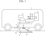
- FIG. 1 is a view schematically showing an automatic charging system in the embodiment.
- the automatic charging system includes a vehicle 1 and an automatic charging apparatus 8.
- the automatic charging system is a system in which the automatic charging apparatus 8 automatically connects to the vehicle 1 parked in a parking space in which the automatic charging apparatus 8 is provided and supplies electricity to the vehicle 1.
- the vehicle 1 is an electrified vehicle capable of being charged with electricity supplied from an external power source and is configured by a battery electric vehicle (BEV) and a plug-in hybrid electric vehicle (PHEV), for example.
- BEV battery electric vehicle
- PHEV plug-in hybrid electric vehicle
- the vehicle 1 is a vehicle that can be parked in the parking space in which the automatic charging apparatus 8 is installed.
- the vehicle 1 includes an ECU 2, a battery 3, a charging relay 4, a charging inlet 5, electricity wiring 61, 62, 63, a communication line 71, a communication apparatus (not shown), and the like.
- the charging inlet 5 is a charging port and receives electricity supplied from the automatic charging apparatus 8 connected to the external power source (not shown). As shown in FIG. 1 , the charging inlet 5 is provided on a bottom portion of the vehicle 1. A charging connector 82 of the automatic charging apparatus 8 is connected to the charging inlet 5. The vehicle 1 can receive electricity supplied from the automatic charging apparatus 8 in a state in which the charging connector 82 is inserted into (connected to) the charging inlet 5. The vehicle 1 supplies the electricity received from the automatic charging apparatus 8 to the battery 3 from the charging inlet 5. The charging inlet 5 and the battery 3 are electrically connected to each other via the electricity wiring 63, the charging relay 4, the electricity wiring 62, and the electricity wiring 61. The charging relay 4 is connected to the ECU 2 via the communication line 71.
- the charging inlet 5 has an inlet case 51 that is a casing in which charging terminals 511 (see FIG. 2 ) described below to which the charging connector 82 is electrically connected is provided on the inside, and an inlet cover 52 that is a cover member that opens and closes an opening portion of the inlet case 51.
- the opening portion of the inlet case 51 is formed by opening a side surface on one side in the front-rear direction of the vehicle 1 in the box-like inlet case 51, for example.
- the inlet cover 52 is attached to the inlet case 51 by a hinge (not shown) and the opening portion of the inlet case 51 can be rotated in an opening direction and a closing direction about the hinge serving as a rotation center.
- the inlet cover 52 is configured to automatically open and close with respect to the inlet case 51 by an automatic opening/closing apparatus (not shown) provided in the charging inlet 5.
- the automatic opening/closing apparatus has a cover driving motor (not shown) that is a driving source for opening and closing the inlet cover 52 by rotating the inlet cover 52 about the hinge serving as a rotation center.
- the driving of the cover driving motor is controlled by the ECU 2.
- the automatic opening/closing apparatus has a torque detection sensor (not shown) that detects the torque of the cover driving motor. Information relating to the torque of the cover driving motor detected by the torque detection sensor is transmitted to the ECU 2 and used in the control of opening/closing operation of the inlet cover 52.
- the inlet cover 52 may also be provided so as to be manually openable and closable with respect to the inlet case 51 when a user operates the inlet cover 52.
- the charging connector 82 is inserted from the opening portion of the inlet case 51 in a state in which the inlet cover 52 is open.
- the charging terminals 511 of the charging inlet 5 and a terminal (not shown) of the charging connector 82 are electrically connected to each other.
- the battery 3 is an electricity storage apparatus and is an in-vehicle battery with which external charging is possible.
- the battery 3 is a secondary battery that can store therein electricity supplied from the charging inlet 5.
- the battery 3 is configured by a lithium ion battery, for example.
- the battery 3 stores therein electricity supplied from the external power source connected via the charging inlet 5.
- the battery 3 supplies electricity to a traveling motor of the vehicle 1.
- the traveling motor is electrically connected to the battery 3 via the electricity wiring 61.
- the ECU 2 is an electronic control apparatus that executes charging control of storing electricity received by the charging inlet 5 into the battery 3.
- the electronic control apparatus includes a processor and a memory (main storage unit).
- the processor is configured by a central processing unit (CPU) and the like.
- the memory is configured by a random access memory (RAM), a read only memory (ROM), and the like. Signals from various sensors mounted on the vehicle 1 are input to the ECU 2.
- the ECU 2 executes the charging control on the basis of the signals input from the various sensors.
- the automatic charging apparatus 8 is equipment that is installed in the parking space and supplies electricity to the vehicle 1 by automatically connecting the charging connector 82 to the vehicle 1 that has finished parking in the parking space, for example.
- the automatic charging apparatus 8 includes a charging apparatus main body 81, the charging connector 82, a connection mechanism 83, a control apparatus (not shown), and a communication apparatus (not shown).
- the charging apparatus main body 81 is installed on the ground of the parking space and is electrically connected to an external power source such as a commercial power source and a household power source, for example.
- the charging connector 82 is a connector automatically connected to the charging inlet 5.
- the charging connector 82 is joined to the connection mechanism 83.
- the connection mechanism 83 is controlled by the control apparatus provided in the charging apparatus main body 81.
- the position of the charging connector 82 can be automatically changed by the connection mechanism 83.
- the charging connector 82 is electrically connected to the charging apparatus main body 81 via a charging cable (not shown). In the automatic charging apparatus 8, the electricity supplied from the external power source is converted to electricity to be transmitted and is output to the charging connector 82.
- the charging connector 82 is automatically connected to the charging inlet 5 and electricity is supplied from the automatic charging apparatus 8 to the vehicle 1 in a state in which wireless communication by communication apparatuses of the vehicle 1 and the automatic charging apparatus 8 is established between the vehicle 1 and the automatic charging apparatus 8. In the vehicle 1, control of supplying electricity received by the charging inlet 5 to the battery 3 is performed.
- the charging relay 4 is a relay for electrically connecting and cutting off the battery 3 and the charging inlet 5 to and from each other.
- the charging relay 4 is electrically connected between the battery 3 and the charging inlet 5.
- the charging relay 4 is electrically connected to the battery 3 via the electricity wiring 61, 62.
- the charging relay 4 is electrically connected to the charging inlet 5 via the electricity wiring 63.
- the charging relay 4 switches between the closed state and the open state in accordance with a control signal from the ECU 2.
- the ECU 2 turns the charging relay 4 ON and places the charging relay 4 in a closed state when automatic charging is performed by the automatic charging apparatus 8 and turns the charging relay 4 OFF and places the charging relay 4 in an open state when automatic charging is not performed by the automatic charging apparatus 8, for example.
- FIG. 2 is a perspective view of the charging inlet 5 diagonally seen from a side in a state in which the inlet cover 52 is open.
- FIG. 3 is a perspective view of the charging inlet 5 diagonally seen from above in a state in which the inlet cover 52 is open.
- FIG. 4 is a sectional view of the charging inlet 5 in a state in which the inlet cover 52 is closed.
- the two rod-like charging terminals 511 provided in the inlet case 51 are exposed to the outside.
- FIG. 4 in a state in which the inlet cover 52 is closed in the charging inlet 5, the two charging terminals 511 provided in the inlet case 51 are not exposed to the outside.
- the two charging terminals 511 are electrically connected to the electricity wiring 63 provided in the vehicle 1.
- the two charging terminals 511 are disposed in the inlet case 51 such that distal ends face the opening portion formed in the inlet case 51 covered by the inlet cover 52.
- a heater 53 formed by a heating wire that generates heat by energization for heating the inlet cover 52 is provided in the inlet cover 52.
- the heater 53 is annularly disposed around the entire periphery of edges on the inside of the inlet cover 52.
- the heater 53 is electrically connected to two heater terminals 521 disposed on the inner side of the annularly disposed heater 53.
- the two heater terminals 521 are disposed on an inner wall surface 52a of the inlet cover 52 so as to come into contact with and be electrically connected to the distal ends of the two charging terminals 511 in a state in which the inlet cover 52 is closed with respect to the inlet case 51.
- the inner wall surface 52a of the inlet cover 52 is a surface that faces the distal ends of the charging terminals 511 provided in the inlet case 51.
- the ECU 2 supplies electricity from the battery 3 to the heater 53 by turning the charging relay 4 ON when the outdoor air temperature that is a temperature around the vehicle 1 (charging inlet 5) is less than a preset threshold value, for example, less than 5 [°C] on the basis of a detection result of an air temperature sensor (not shown).
- a preset threshold value for example, less than 5 [°C] on the basis of a detection result of an air temperature sensor (not shown).
- unfreezing is performed by heating the inlet cover 52 by the heat of the heater 53 as above.
- the charging terminals 511 and the heater terminals 521 are electrically connected to each other in a state in which the inlet cover 52 is closed in the charging inlet 5. Therefore, it becomes easy to perform routing of the electricity wiring with respect to the inlet cover 52.
- in the charging inlet 5 it becomes possible to supply electricity to the heater 53 with use of the existing charging relay 4 and electricity wiring 61, 62, 63 for the charging without additionally providing dedicated electricity wiring, relays, and the like for supplying electricity to the heater 53.
- FIG. 5 is a flowchart showing one example of unfreezing control of the inlet cover 52 according to the embodiment.
- FIG. 6 is a flowchart showing one example of control performed by cover freeze determination.
- the ECU 2 performs cover freeze determination that determines whether the inlet cover 52 is frozen (Step S1). As shown in FIG. 6 , when the cover freeze determination is started, the ECU 2 determines whether a relationship of the outdoor air temperature ⁇ 5 [°C] is satisfied on the basis of a detection result of a temperature sensor provided in the vehicle 1 (Step S11). When the ECU 2 determines that the relationship of the outdoor air temperature ⁇ 5 [°C] is not satisfied (No in Step S11), the ECU 2 determines that the inlet cover 52 is not frozen (freeze determination: OFF) (Step S15). Then, the ECU 2 ends the cover freeze determination and transitions to processing of Step S2 in the flowchart shown in FIG. 5 .
- Step S11 when the ECU 2 determines that the relationship of the outdoor air temperature ⁇ 5 [°C] is satisfied (Yes in Step S11), the ECU 2 turns ON a cover opening motor provided in a driving apparatus that automatically opens and closes the inlet cover 52 and executes an opening operation of the inlet cover 52 (Step S12).
- Step S13 the ECU 2 determines whether the inlet cover 52 has opened (Step S13).
- the ECU 2 determines whether a motor driving torque of the cover opening motor is less than a preset threshold value torque X [Nm] (motor driving torque ⁇ X [Nm]) (Step S14).
- Step S14 determines that the motor driving torque is less than threshold value torque X [Nm] (motor driving torque ⁇ X [Nm]) (Yes in Step S14).
- the ECU 2 determines that the inlet cover 52 is not frozen (freeze determination: OFF) (Step S15). Then, the ECU 2 ends the cover freeze determination and transitions to the processing of Step S2 in the flowchart shown in FIG. 5 .
- Step S13 determines that the inlet cover 52 is not open (cover open: NO) in Step S13 (No in Step S13).
- the ECU 2 determines that the inlet cover 52 is frozen (freeze determination: ON) (Step S16). Then, the ECU 2 ends the cover freeze determination and transitions to the processing of Step S2 in the flowchart shown in FIG. 5 .
- Step S14 When the ECU 2 determines that the motor driving torque is not less than the threshold value torque X [Nm] (the motor driving torque ⁇ X [Nm]) in Step S14 (No in Step S14), the ECU 2 determines that the inlet cover 52 is frozen (freeze determination: ON) (Step S16). Then, the ECU 2 ends the cover freeze determination and transitions to the processing of Step S2 in the flowchart shown in FIG. 5 .
- the ECU 2 determines whether the inlet cover 52 is frozen on the basis of the determination result of the cover freeze determination (Step S2).
- the ECU 2 determines that the inlet cover 52 is frozen (Yes in Step S2)
- the ECU 2 turns the charging relay 4 ON and places the charging relay 4 in a closed state (Step S3).
- electricity is supplied to the charging terminals 511 of the charging inlet 5 from the battery 3, the electricity is supplied to the heater 53 via the heater terminals 521 of the inlet cover 52, and the inlet cover 52 is heated.
- Step S1 the ECU 2 transitions to the processing of Step S1 after a predetermined amount of time elapses after the charging relay 4 is turned ON, for example. Meanwhile, when the ECU 2 determines that the inlet cover 52 is not frozen (No in Step S2), the charging relay 4 is turned OFF and the charging relay 4 is placed in an open state (Step S4). Then, the ECU 2 ends the series of cover freeze prevention control and transitions to a predetermined automatic charging control.
- the inlet cover 52 may be determined to be frozen when the processing of Step S1 to Step S3 is repeated by a predetermined number of times, in other words, even when it is determined that the inlet cover 52 is frozen in the cover freeze determination, the charging relay is turned ON, and the inlet cover 52 is heated by the heater 53 by a predetermined number of times in the flowchart shown in FIG. 5 .
- the ECU 2 executes fail processing of ending the series of unfreezing control of the inlet cover 52 by determining that some kind of abnormality has occurred, for example.
- a temperature sensor that detects the temperature of the charging terminals 511 is provided in the charging inlet 5, and the fail processing is executed as a result of determining that an energization abnormality has occurred in not only the charging terminals 511 but also the heater 53 when the temperature of the charging terminals 511 is less than a predetermined temperature even when the charging relay 4 is turned ON.
- the fail processing it is desired that the ECU 2 notifies the user of the vehicle 1 by performing display on a display apparatus such as a display (not shown) provided in the vehicle 1, for example.
Landscapes
- Engineering & Computer Science (AREA)
- Transportation (AREA)
- Mechanical Engineering (AREA)
- Power Engineering (AREA)
- Microelectronics & Electronic Packaging (AREA)
- Life Sciences & Earth Sciences (AREA)
- Sustainable Development (AREA)
- Sustainable Energy (AREA)
- Chemical & Material Sciences (AREA)
- Combustion & Propulsion (AREA)
- Electric Propulsion And Braking For Vehicles (AREA)
- Charge And Discharge Circuits For Batteries Or The Like (AREA)
Abstract
A charging inlet (5) of the present invention includes: a casing (51); and a cover member (52). The charging inlet (5) electrically connects the charging terminal (511) and a terminal of a charging connector to each other by inserting the charging connector from the opening portion in a state in which the cover member (52) is open. The charging inlet further includes: a heater (53) provided in the cover member (52) and heating the cover member by generating heat by energization; and a heater terminal (521) provided on the cover member and electrically connected to the heater (53). The heater terminal (521) is disposed on a surface (52a) of the cover member (52) facing the charging terminal (511) such that the charging terminal (511) and the heater terminal (521) come into contact with each other in a state in which the cover member is closed.
Description
- The present invention relates to a charging inlet.
-
Japanese Unexamined Patent Application Publication No. 2016-088251 - In a configuration in which electricity is supplied to a heater provided in a cover member that opens and closes an opening portion of a charging inlet from a battery of a vehicle with use of dedicated electricity wiring, it becomes difficult to perform routing of the electricity wiring with respect to the cover member, and the structure becomes complicated.
- The present invention has been made in view of the problem described above and an object thereof is to provide a charging inlet capable of unfreezing a cover member by a simple structure.
- In order to solve the problem and achieve the object described above, a charging inlet includes: a casing inside which a charging terminal to be electrically connected to an electricity storage apparatus provided in a vehicle is housed; and a cover member provided in the casing so as to be able to open and close an opening portion formed in the casing. The charging inlet electrically connects the charging terminal and a terminal of a charging connector to each other by inserting the charging connector from the opening portion in a state in which the cover member is open. The charging inlet further includes: a heater that is provided in the cover member and heats the cover member by generating heat by energization; and a heater terminal provided on the cover member and electrically connected to the heater. The heater terminal is disposed on a surface of the cover member facing the charging terminal such that the charging terminal and the heater terminal come into contact with each other in a state in which the cover member is closed.
- As a result, the charging inlet according to the present invention is capable of unfreezing the cover member by a simple structure.
- In the above, an automatic opening/closing apparatus that automatically opens and closes the cover member may further be included.
- As a result, the cover member can automatically open after the cover member is unfrozen.
- The charging inlet according to the present invention exhibits the effect of being able to unfreeze the cover member by a simple structure.
- Features, advantages, and technical and industrial significance of exemplary embodiments of the invention will be described below with reference to the accompanying drawings, in which like signs denote like elements, and wherein:
-
FIG. 1 is a view schematically showing an automatic parking system in an embodiment; -
FIG. 2 is a perspective view of an inlet diagonally seen from a side in a state in which an inlet cover is open; -
FIG. 3 is a perspective view of the inlet diagonally seen from above in the state in which the inlet cover is open; -
FIG. 4 is a sectional view of the inlet in a state in which the inlet cover is closed; -
FIG. 5 is a flowchart showing one example of unfreezing control of the inlet cover according to the embodiment; and -
FIG. 6 is a flowchart showing one example of control performed by cover freeze determination. - An embodiment of a charging inlet according to the present invention is described below. The present invention is not limited by the present embodiment.
-
FIG. 1 is a view schematically showing an automatic charging system in the embodiment. The automatic charging system includes avehicle 1 and anautomatic charging apparatus 8. The automatic charging system is a system in which theautomatic charging apparatus 8 automatically connects to thevehicle 1 parked in a parking space in which theautomatic charging apparatus 8 is provided and supplies electricity to thevehicle 1. - The
vehicle 1 is an electrified vehicle capable of being charged with electricity supplied from an external power source and is configured by a battery electric vehicle (BEV) and a plug-in hybrid electric vehicle (PHEV), for example. Thevehicle 1 is a vehicle that can be parked in the parking space in which theautomatic charging apparatus 8 is installed. Thevehicle 1 includes anECU 2, abattery 3, acharging relay 4, acharging inlet 5,electricity wiring communication line 71, a communication apparatus (not shown), and the like. - The
charging inlet 5 is a charging port and receives electricity supplied from theautomatic charging apparatus 8 connected to the external power source (not shown). As shown inFIG. 1 , thecharging inlet 5 is provided on a bottom portion of thevehicle 1. Acharging connector 82 of theautomatic charging apparatus 8 is connected to thecharging inlet 5. Thevehicle 1 can receive electricity supplied from theautomatic charging apparatus 8 in a state in which thecharging connector 82 is inserted into (connected to) thecharging inlet 5. Thevehicle 1 supplies the electricity received from theautomatic charging apparatus 8 to thebattery 3 from thecharging inlet 5. Thecharging inlet 5 and thebattery 3 are electrically connected to each other via theelectricity wiring 63, thecharging relay 4, the electricity wiring 62, and theelectricity wiring 61. Thecharging relay 4 is connected to the ECU 2 via thecommunication line 71. - The
charging inlet 5 has aninlet case 51 that is a casing in which charging terminals 511 (seeFIG. 2 ) described below to which thecharging connector 82 is electrically connected is provided on the inside, and aninlet cover 52 that is a cover member that opens and closes an opening portion of theinlet case 51. The opening portion of theinlet case 51 is formed by opening a side surface on one side in the front-rear direction of thevehicle 1 in the box-like inlet case 51, for example. Theinlet cover 52 is attached to theinlet case 51 by a hinge (not shown) and the opening portion of theinlet case 51 can be rotated in an opening direction and a closing direction about the hinge serving as a rotation center. Theinlet cover 52 is configured to automatically open and close with respect to theinlet case 51 by an automatic opening/closing apparatus (not shown) provided in thecharging inlet 5. The automatic opening/closing apparatus has a cover driving motor (not shown) that is a driving source for opening and closing theinlet cover 52 by rotating theinlet cover 52 about the hinge serving as a rotation center. The driving of the cover driving motor is controlled by the ECU 2. The automatic opening/closing apparatus has a torque detection sensor (not shown) that detects the torque of the cover driving motor. Information relating to the torque of the cover driving motor detected by the torque detection sensor is transmitted to theECU 2 and used in the control of opening/closing operation of theinlet cover 52. Theinlet cover 52 may also be provided so as to be manually openable and closable with respect to theinlet case 51 when a user operates theinlet cover 52. In thecharging inlet 5, thecharging connector 82 is inserted from the opening portion of theinlet case 51 in a state in which theinlet cover 52 is open. As a result, thecharging terminals 511 of thecharging inlet 5 and a terminal (not shown) of thecharging connector 82 are electrically connected to each other. - The
battery 3 is an electricity storage apparatus and is an in-vehicle battery with which external charging is possible. Thebattery 3 is a secondary battery that can store therein electricity supplied from thecharging inlet 5. Thebattery 3 is configured by a lithium ion battery, for example. Thebattery 3 stores therein electricity supplied from the external power source connected via thecharging inlet 5. Thebattery 3 supplies electricity to a traveling motor of thevehicle 1. The traveling motor is electrically connected to thebattery 3 via theelectricity wiring 61. - The ECU 2 is an electronic control apparatus that executes charging control of storing electricity received by the
charging inlet 5 into thebattery 3. The electronic control apparatus includes a processor and a memory (main storage unit). The processor is configured by a central processing unit (CPU) and the like. The memory is configured by a random access memory (RAM), a read only memory (ROM), and the like. Signals from various sensors mounted on thevehicle 1 are input to theECU 2. TheECU 2 executes the charging control on the basis of the signals input from the various sensors. - The
automatic charging apparatus 8 is equipment that is installed in the parking space and supplies electricity to thevehicle 1 by automatically connecting the chargingconnector 82 to thevehicle 1 that has finished parking in the parking space, for example. Theautomatic charging apparatus 8 includes a charging apparatusmain body 81, the chargingconnector 82, aconnection mechanism 83, a control apparatus (not shown), and a communication apparatus (not shown). - The charging apparatus
main body 81 is installed on the ground of the parking space and is electrically connected to an external power source such as a commercial power source and a household power source, for example. The chargingconnector 82 is a connector automatically connected to the charginginlet 5. The chargingconnector 82 is joined to theconnection mechanism 83. Theconnection mechanism 83 is controlled by the control apparatus provided in the charging apparatusmain body 81. The position of the chargingconnector 82 can be automatically changed by theconnection mechanism 83. The chargingconnector 82 is electrically connected to the charging apparatusmain body 81 via a charging cable (not shown). In theautomatic charging apparatus 8, the electricity supplied from the external power source is converted to electricity to be transmitted and is output to the chargingconnector 82. - It is possible to automatically insert the charging
connector 82 into the charginginlet 5 and perform external charging in a state in which thevehicle 1 has finished parking in the parking space in which theautomatic charging apparatus 8 is installed. In the automatic charging system, the chargingconnector 82 is automatically connected to the charginginlet 5 and electricity is supplied from theautomatic charging apparatus 8 to thevehicle 1 in a state in which wireless communication by communication apparatuses of thevehicle 1 and theautomatic charging apparatus 8 is established between thevehicle 1 and theautomatic charging apparatus 8. In thevehicle 1, control of supplying electricity received by the charginginlet 5 to thebattery 3 is performed. - The charging
relay 4 is a relay for electrically connecting and cutting off thebattery 3 and the charginginlet 5 to and from each other. The chargingrelay 4 is electrically connected between thebattery 3 and the charginginlet 5. The chargingrelay 4 is electrically connected to thebattery 3 via theelectricity wiring relay 4 is electrically connected to the charginginlet 5 via theelectricity wiring 63. The chargingrelay 4 switches between the closed state and the open state in accordance with a control signal from theECU 2. TheECU 2 turns the chargingrelay 4 ON and places the chargingrelay 4 in a closed state when automatic charging is performed by theautomatic charging apparatus 8 and turns the chargingrelay 4 OFF and places the chargingrelay 4 in an open state when automatic charging is not performed by theautomatic charging apparatus 8, for example. -
FIG. 2 is a perspective view of the charginginlet 5 diagonally seen from a side in a state in which theinlet cover 52 is open.FIG. 3 is a perspective view of the charginginlet 5 diagonally seen from above in a state in which theinlet cover 52 is open.FIG. 4 is a sectional view of the charginginlet 5 in a state in which theinlet cover 52 is closed. - As shown in
FIG. 2 andFIG. 3 , in a state in which theinlet cover 52 is open in the charginginlet 5, the two rod-like charging terminals 511 provided in theinlet case 51 are exposed to the outside. As shown inFIG. 4 , in a state in which theinlet cover 52 is closed in the charginginlet 5, the twocharging terminals 511 provided in theinlet case 51 are not exposed to the outside. The twocharging terminals 511 are electrically connected to theelectricity wiring 63 provided in thevehicle 1. The twocharging terminals 511 are disposed in theinlet case 51 such that distal ends face the opening portion formed in theinlet case 51 covered by theinlet cover 52. - In the charging
inlet 5, aheater 53 formed by a heating wire that generates heat by energization for heating theinlet cover 52 is provided in theinlet cover 52. Theheater 53 is annularly disposed around the entire periphery of edges on the inside of theinlet cover 52. On the inside of theinlet cover 52, theheater 53 is electrically connected to twoheater terminals 521 disposed on the inner side of the annularlydisposed heater 53. The twoheater terminals 521 are disposed on aninner wall surface 52a of theinlet cover 52 so as to come into contact with and be electrically connected to the distal ends of the twocharging terminals 511 in a state in which theinlet cover 52 is closed with respect to theinlet case 51. Theinner wall surface 52a of theinlet cover 52 is a surface that faces the distal ends of the chargingterminals 511 provided in theinlet case 51. - In the
vehicle 1 according to the embodiment, there is a concern that theinlet cover 52 cannot automatically open with respect to theinlet case 51 when theinlet cover 52 is frozen when automatic charging is performed by theautomatic charging apparatus 8. Therefore, theECU 2 supplies electricity from thebattery 3 to theheater 53 by turning the chargingrelay 4 ON when the outdoor air temperature that is a temperature around the vehicle 1 (charging inlet 5) is less than a preset threshold value, for example, less than 5 [°C] on the basis of a detection result of an air temperature sensor (not shown). In the charginginlet 5 included in thevehicle 1 according to the embodiment, unfreezing is performed by heating theinlet cover 52 by the heat of theheater 53 as above. - In the
vehicle 1 according to the embodiment, the chargingterminals 511 and theheater terminals 521 are electrically connected to each other in a state in which theinlet cover 52 is closed in the charginginlet 5. Therefore, it becomes easy to perform routing of the electricity wiring with respect to theinlet cover 52. In thevehicle 1 according to the embodiment, in the charginginlet 5, it becomes possible to supply electricity to theheater 53 with use of the existingcharging relay 4 andelectricity wiring heater 53. As a result, it becomes possible to unfreeze theinlet cover 52 by a simple structure in the charginginlet 5 included in thevehicle 1 according to the embodiment. -
FIG. 5 is a flowchart showing one example of unfreezing control of theinlet cover 52 according to the embodiment.FIG. 6 is a flowchart showing one example of control performed by cover freeze determination. - First, as shown in
FIG. 5 , theECU 2 performs cover freeze determination that determines whether theinlet cover 52 is frozen (Step S1). As shown inFIG. 6 , when the cover freeze determination is started, theECU 2 determines whether a relationship of the outdoor air temperature<5 [°C] is satisfied on the basis of a detection result of a temperature sensor provided in the vehicle 1 (Step S11). When theECU 2 determines that the relationship of the outdoor air temperature<5 [°C] is not satisfied (No in Step S11), theECU 2 determines that theinlet cover 52 is not frozen (freeze determination: OFF) (Step S15). Then, theECU 2 ends the cover freeze determination and transitions to processing of Step S2 in the flowchart shown inFIG. 5 . - Meanwhile, when the
ECU 2 determines that the relationship of the outdoor air temperature<5 [°C] is satisfied (Yes in Step S11), theECU 2 turns ON a cover opening motor provided in a driving apparatus that automatically opens and closes theinlet cover 52 and executes an opening operation of the inlet cover 52 (Step S12). Next, theECU 2 determines whether theinlet cover 52 has opened (Step S13). When theECU 2 determines that theinlet cover 52 has opened (cover open: OK) (Yes in Step S13), theECU 2 determines whether a motor driving torque of the cover opening motor is less than a preset threshold value torque X [Nm] (motor driving torque<X [Nm]) (Step S14). When theECU 2 determines that the motor driving torque is less than threshold value torque X [Nm] (motor driving torque<X [Nm]) (Yes in Step S14), theECU 2 determines that theinlet cover 52 is not frozen (freeze determination: OFF) (Step S15). Then, theECU 2 ends the cover freeze determination and transitions to the processing of Step S2 in the flowchart shown inFIG. 5 . - When the
ECU 2 determines that theinlet cover 52 is not open (cover open: NO) in Step S13 (No in Step S13), theECU 2 determines that theinlet cover 52 is frozen (freeze determination: ON) (Step S16). Then, theECU 2 ends the cover freeze determination and transitions to the processing of Step S2 in the flowchart shown inFIG. 5 . - When the
ECU 2 determines that the motor driving torque is not less than the threshold value torque X [Nm] (the motor driving torque≥X [Nm]) in Step S14 (No in Step S14), theECU 2 determines that theinlet cover 52 is frozen (freeze determination: ON) (Step S16). Then, theECU 2 ends the cover freeze determination and transitions to the processing of Step S2 in the flowchart shown inFIG. 5 . - Returning to
FIG. 5 , after the cover freeze determination in Step S1, theECU 2 determines whether theinlet cover 52 is frozen on the basis of the determination result of the cover freeze determination (Step S2). When theECU 2 determines that theinlet cover 52 is frozen (Yes in Step S2), theECU 2 turns the chargingrelay 4 ON and places the chargingrelay 4 in a closed state (Step S3). As a result, electricity is supplied to the chargingterminals 511 of the charginginlet 5 from thebattery 3, the electricity is supplied to theheater 53 via theheater terminals 521 of theinlet cover 52, and theinlet cover 52 is heated. Then, theECU 2 transitions to the processing of Step S1 after a predetermined amount of time elapses after the chargingrelay 4 is turned ON, for example. Meanwhile, when theECU 2 determines that theinlet cover 52 is not frozen (No in Step S2), the chargingrelay 4 is turned OFF and the chargingrelay 4 is placed in an open state (Step S4). Then, theECU 2 ends the series of cover freeze prevention control and transitions to a predetermined automatic charging control. - In the
vehicle 1 according to the embodiment, when theinlet cover 52 freezes, theinlet cover 52 can be unfrozen as a result of turning the chargingrelay 4 ON, supplying electricity to theheater 53 from thebattery 3, and heating theinlet cover 52 by the heat of theheater 53. After theinlet cover 52 is unfrozen and becomes automatically openable, theECU 2 can start the automatic charging by communicating with theautomatic charging apparatus 8 and automatically connecting the chargingconnector 82 to the charginginlet 5 by theautomatic charging apparatus 8. - In the
vehicle 1 according to the embodiment, there is a possibility that theinlet cover 52 may be determined to be frozen when the processing of Step S1 to Step S3 is repeated by a predetermined number of times, in other words, even when it is determined that theinlet cover 52 is frozen in the cover freeze determination, the charging relay is turned ON, and theinlet cover 52 is heated by theheater 53 by a predetermined number of times in the flowchart shown inFIG. 5 . In this case, theECU 2 executes fail processing of ending the series of unfreezing control of theinlet cover 52 by determining that some kind of abnormality has occurred, for example. For example, a temperature sensor that detects the temperature of the chargingterminals 511 is provided in the charginginlet 5, and the fail processing is executed as a result of determining that an energization abnormality has occurred in not only the chargingterminals 511 but also theheater 53 when the temperature of the chargingterminals 511 is less than a predetermined temperature even when the chargingrelay 4 is turned ON. When the fail processing is executed, it is desired that theECU 2 notifies the user of thevehicle 1 by performing display on a display apparatus such as a display (not shown) provided in thevehicle 1, for example.
Claims (2)
- A charging inlet (5), comprising:a casing (51) inside which a charging terminal (511) to be electrically connected to an electricity storage apparatus (3) provided in a vehicle (1) is housed; anda cover member (52) provided in the casing (51) so as to be able to open and close an opening portion formed in the casing (51), the charging inlet (5) electrically connecting the charging terminal (511) and a terminal of a charging connector (82) to each other by inserting the charging connector (82) from the opening portion in a state in which the cover member (52) is open, the charging inlet (5) further comprising:a heater (53) that is provided in the cover member (52) and heats the cover member (52) by generating heat by energization; anda heater terminal (521) provided on the cover member (52) and electrically connected to the heater (53), wherein the heater terminal (521) is disposed on a surface (52a) of the cover member (52) facing the charging terminal (511) such that the charging terminal (511) and the heater terminal (521) come into contact with each other in a state in which the cover member (52) is closed.
- The charging inlet (5) according to claim 1, further comprising an automatic opening/closing apparatus that automatically opens and closes the cover member (52).
Applications Claiming Priority (1)
| Application Number | Priority Date | Filing Date | Title |
|---|---|---|---|
| JP2023043413A JP7790382B2 (en) | 2023-03-17 | 2023-03-17 | Charging inlet |
Publications (1)
| Publication Number | Publication Date |
|---|---|
| EP4438388A1 true EP4438388A1 (en) | 2024-10-02 |
Family
ID=90038188
Family Applications (1)
| Application Number | Title | Priority Date | Filing Date |
|---|---|---|---|
| EP24158950.6A Pending EP4438388A1 (en) | 2023-03-17 | 2024-02-21 | Charging inlet |
Country Status (5)
| Country | Link |
|---|---|
| US (1) | US20240313485A1 (en) |
| EP (1) | EP4438388A1 (en) |
| JP (1) | JP7790382B2 (en) |
| KR (1) | KR102842862B1 (en) |
| CN (1) | CN118665609A (en) |
Citations (3)
| Publication number | Priority date | Publication date | Assignee | Title |
|---|---|---|---|---|
| JP2016088251A (en) | 2014-11-04 | 2016-05-23 | 三菱自動車工業株式会社 | Vehicle energy supply structure |
| JP2016088250A (en) * | 2014-11-04 | 2016-05-23 | 三菱自動車工業株式会社 | Control device for vehicle energy supply unit |
| JP2020156250A (en) * | 2019-03-22 | 2020-09-24 | 株式会社Subaru | Vehicle control device |
-
2023
- 2023-03-17 JP JP2023043413A patent/JP7790382B2/en active Active
-
2024
- 2024-02-13 KR KR1020240020523A patent/KR102842862B1/en active Active
- 2024-02-21 EP EP24158950.6A patent/EP4438388A1/en active Pending
- 2024-02-22 US US18/584,501 patent/US20240313485A1/en active Pending
- 2024-03-06 CN CN202410256384.7A patent/CN118665609A/en active Pending
Patent Citations (3)
| Publication number | Priority date | Publication date | Assignee | Title |
|---|---|---|---|---|
| JP2016088251A (en) | 2014-11-04 | 2016-05-23 | 三菱自動車工業株式会社 | Vehicle energy supply structure |
| JP2016088250A (en) * | 2014-11-04 | 2016-05-23 | 三菱自動車工業株式会社 | Control device for vehicle energy supply unit |
| JP2020156250A (en) * | 2019-03-22 | 2020-09-24 | 株式会社Subaru | Vehicle control device |
Also Published As
| Publication number | Publication date |
|---|---|
| US20240313485A1 (en) | 2024-09-19 |
| KR102842862B1 (en) | 2025-08-05 |
| JP2024132581A (en) | 2024-10-01 |
| KR20240140800A (en) | 2024-09-24 |
| JP7790382B2 (en) | 2025-12-23 |
| CN118665609A (en) | 2024-09-20 |
Similar Documents
| Publication | Publication Date | Title |
|---|---|---|
| US8760116B2 (en) | Charger and charging system | |
| CN108973708B (en) | Electric vehicle and reporting system thereof | |
| CN109017340B (en) | Vehicle architecture, electrical system, and control algorithm for arbitrating vehicle charging | |
| JP4781425B2 (en) | Power supply system between vehicle and house | |
| US9573476B2 (en) | Method and apparatus for controller wakeup using control pilot signal from charge port | |
| CN114475304A (en) | Portable high-voltage vehicle charging system | |
| JPH09285022A (en) | Electric vehicle charging display device | |
| CN114123369A (en) | Charging system, vehicle, charging control device, and charging method | |
| CN108973712B (en) | Vehicle with a steering wheel | |
| US10343538B2 (en) | Controlling charge levels of vehicle batteries based on battery charge states and vehicle operating modes | |
| US20190084506A1 (en) | Power receptacle system for an automotive vehicle | |
| JP2020072483A (en) | Vehicle and portable device | |
| CN117021982A (en) | Intelligent vehicle systems and control logic for battery charging control and information display | |
| EP4438388A1 (en) | Charging inlet | |
| JPH09163510A (en) | Electric vehicle charging control device | |
| JP7172608B2 (en) | vehicle | |
| JP2018157623A (en) | vehicle | |
| JP2013009460A (en) | Charging inlet lid control device | |
| JP2021013285A (en) | Charge control device | |
| JP2018026298A (en) | Battery heating control device | |
| CN115958971A (en) | System and method for predicting charging events and preparing an electric vehicle for charging | |
| JP6110071B2 (en) | Vehicle charging system | |
| US12552269B2 (en) | Vehicle battery power monitoring and management systems | |
| CN119366085A (en) | Butt joint interlocking system and method | |
| CN115320521A (en) | Apparatus and method for managing battery of vehicle |
Legal Events
| Date | Code | Title | Description |
|---|---|---|---|
| PUAI | Public reference made under article 153(3) epc to a published international application that has entered the european phase |
Free format text: ORIGINAL CODE: 0009012 |
|
| STAA | Information on the status of an ep patent application or granted ep patent |
Free format text: STATUS: REQUEST FOR EXAMINATION WAS MADE |
|
| 17P | Request for examination filed |
Effective date: 20240221 |
|
| AK | Designated contracting states |
Kind code of ref document: A1 Designated state(s): AL AT BE BG CH CY CZ DE DK EE ES FI FR GB GR HR HU IE IS IT LI LT LU LV MC ME MK MT NL NO PL PT RO RS SE SI SK SM TR |