EP4438382A1 - Fuel cell as an electrolyzer in fuel cell electric vehicles for onboard hydrogen production - Google Patents
Fuel cell as an electrolyzer in fuel cell electric vehicles for onboard hydrogen production Download PDFInfo
- Publication number
- EP4438382A1 EP4438382A1 EP23165840.2A EP23165840A EP4438382A1 EP 4438382 A1 EP4438382 A1 EP 4438382A1 EP 23165840 A EP23165840 A EP 23165840A EP 4438382 A1 EP4438382 A1 EP 4438382A1
- Authority
- EP
- European Patent Office
- Prior art keywords
- hydrogen
- electrolyzers
- fuel cells
- generated
- water
- Prior art date
- Legal status (The legal status is an assumption and is not a legal conclusion. Google has not performed a legal analysis and makes no representation as to the accuracy of the status listed.)
- Pending
Links
- UFHFLCQGNIYNRP-UHFFFAOYSA-N Hydrogen Chemical compound [H][H] UFHFLCQGNIYNRP-UHFFFAOYSA-N 0.000 title claims abstract description 294
- 239000001257 hydrogen Substances 0.000 title claims abstract description 273
- 229910052739 hydrogen Inorganic materials 0.000 title claims abstract description 273
- 239000000446 fuel Substances 0.000 title claims abstract description 127
- 238000004519 manufacturing process Methods 0.000 title claims abstract description 33
- XLYOFNOQVPJJNP-UHFFFAOYSA-N water Substances O XLYOFNOQVPJJNP-UHFFFAOYSA-N 0.000 claims abstract description 77
- 229910001868 water Inorganic materials 0.000 claims abstract description 75
- 238000003860 storage Methods 0.000 claims abstract description 52
- 230000005611 electricity Effects 0.000 claims abstract description 40
- 238000000034 method Methods 0.000 claims abstract description 31
- 230000001172 regenerating effect Effects 0.000 claims abstract description 20
- QVGXLLKOCUKJST-UHFFFAOYSA-N atomic oxygen Chemical compound [O] QVGXLLKOCUKJST-UHFFFAOYSA-N 0.000 claims description 47
- 239000001301 oxygen Substances 0.000 claims description 47
- 229910052760 oxygen Inorganic materials 0.000 claims description 47
- 238000004146 energy storage Methods 0.000 claims description 16
- 238000003306 harvesting Methods 0.000 claims description 14
- 239000012528 membrane Substances 0.000 claims description 12
- 238000005868 electrolysis reaction Methods 0.000 description 28
- 230000008901 benefit Effects 0.000 description 18
- 238000006243 chemical reaction Methods 0.000 description 18
- 230000008569 process Effects 0.000 description 10
- 239000005518 polymer electrolyte Substances 0.000 description 9
- 238000000746 purification Methods 0.000 description 7
- 238000001816 cooling Methods 0.000 description 6
- 150000002431 hydrogen Chemical class 0.000 description 6
- 238000004378 air conditioning Methods 0.000 description 3
- 238000003487 electrochemical reaction Methods 0.000 description 3
- 239000000126 substance Substances 0.000 description 3
- OKTJSMMVPCPJKN-UHFFFAOYSA-N Carbon Chemical compound [C] OKTJSMMVPCPJKN-UHFFFAOYSA-N 0.000 description 2
- 230000001133 acceleration Effects 0.000 description 2
- 229910052799 carbon Inorganic materials 0.000 description 2
- 238000000354 decomposition reaction Methods 0.000 description 2
- 230000009977 dual effect Effects 0.000 description 2
- 238000001914 filtration Methods 0.000 description 2
- 239000002828 fuel tank Substances 0.000 description 2
- 239000007789 gas Substances 0.000 description 2
- XLYOFNOQVPJJNP-ZSJDYOACSA-N heavy water Substances [2H]O[2H] XLYOFNOQVPJJNP-ZSJDYOACSA-N 0.000 description 2
- 230000007246 mechanism Effects 0.000 description 2
- VNWKTOKETHGBQD-UHFFFAOYSA-N methane Chemical compound C VNWKTOKETHGBQD-UHFFFAOYSA-N 0.000 description 2
- 238000013473 artificial intelligence Methods 0.000 description 1
- 230000005540 biological transmission Effects 0.000 description 1
- 239000003245 coal Substances 0.000 description 1
- 238000002485 combustion reaction Methods 0.000 description 1
- 238000004891 communication Methods 0.000 description 1
- 238000004590 computer program Methods 0.000 description 1
- 238000010276 construction Methods 0.000 description 1
- 239000012530 fluid Substances 0.000 description 1
- 239000002803 fossil fuel Substances 0.000 description 1
- 230000006870 function Effects 0.000 description 1
- 239000005431 greenhouse gas Substances 0.000 description 1
- 238000010438 heat treatment Methods 0.000 description 1
- 125000004435 hydrogen atom Chemical group [H]* 0.000 description 1
- -1 hydrogen ions Chemical class 0.000 description 1
- 239000000463 material Substances 0.000 description 1
- 230000015654 memory Effects 0.000 description 1
- 238000012986 modification Methods 0.000 description 1
- 230000004048 modification Effects 0.000 description 1
- 239000003345 natural gas Substances 0.000 description 1
- 239000003921 oil Substances 0.000 description 1
- 125000004430 oxygen atom Chemical group O* 0.000 description 1
- 230000035699 permeability Effects 0.000 description 1
- 238000005086 pumping Methods 0.000 description 1
- 238000011084 recovery Methods 0.000 description 1
- 230000008929 regeneration Effects 0.000 description 1
- 238000011069 regeneration method Methods 0.000 description 1
- 238000001179 sorption measurement Methods 0.000 description 1
- 230000002459 sustained effect Effects 0.000 description 1
- 238000010792 warming Methods 0.000 description 1
Images




Classifications
-
- H—ELECTRICITY
- H01—ELECTRIC ELEMENTS
- H01M—PROCESSES OR MEANS, e.g. BATTERIES, FOR THE DIRECT CONVERSION OF CHEMICAL ENERGY INTO ELECTRICAL ENERGY
- H01M8/00—Fuel cells; Manufacture thereof
- H01M8/06—Combination of fuel cells with means for production of reactants or for treatment of residues
- H01M8/0606—Combination of fuel cells with means for production of reactants or for treatment of residues with means for production of gaseous reactants
- H01M8/0656—Combination of fuel cells with means for production of reactants or for treatment of residues with means for production of gaseous reactants by electrochemical means
-
- B—PERFORMING OPERATIONS; TRANSPORTING
- B60—VEHICLES IN GENERAL
- B60L—PROPULSION OF ELECTRICALLY-PROPELLED VEHICLES; SUPPLYING ELECTRIC POWER FOR AUXILIARY EQUIPMENT OF ELECTRICALLY-PROPELLED VEHICLES; ELECTRODYNAMIC BRAKE SYSTEMS FOR VEHICLES IN GENERAL; MAGNETIC SUSPENSION OR LEVITATION FOR VEHICLES; MONITORING OPERATING VARIABLES OF ELECTRICALLY-PROPELLED VEHICLES; ELECTRIC SAFETY DEVICES FOR ELECTRICALLY-PROPELLED VEHICLES
- B60L50/00—Electric propulsion with power supplied within the vehicle
- B60L50/50—Electric propulsion with power supplied within the vehicle using propulsion power supplied by batteries or fuel cells
- B60L50/75—Electric propulsion with power supplied within the vehicle using propulsion power supplied by batteries or fuel cells using propulsion power supplied by both fuel cells and batteries
-
- B—PERFORMING OPERATIONS; TRANSPORTING
- B60—VEHICLES IN GENERAL
- B60L—PROPULSION OF ELECTRICALLY-PROPELLED VEHICLES; SUPPLYING ELECTRIC POWER FOR AUXILIARY EQUIPMENT OF ELECTRICALLY-PROPELLED VEHICLES; ELECTRODYNAMIC BRAKE SYSTEMS FOR VEHICLES IN GENERAL; MAGNETIC SUSPENSION OR LEVITATION FOR VEHICLES; MONITORING OPERATING VARIABLES OF ELECTRICALLY-PROPELLED VEHICLES; ELECTRIC SAFETY DEVICES FOR ELECTRICALLY-PROPELLED VEHICLES
- B60L58/00—Methods or circuit arrangements for monitoring or controlling batteries or fuel cells, specially adapted for electric vehicles
- B60L58/30—Methods or circuit arrangements for monitoring or controlling batteries or fuel cells, specially adapted for electric vehicles for monitoring or controlling fuel cells
- B60L58/32—Methods or circuit arrangements for monitoring or controlling batteries or fuel cells, specially adapted for electric vehicles for monitoring or controlling fuel cells for controlling the temperature of fuel cells, e.g. by controlling the electric load
- B60L58/34—Methods or circuit arrangements for monitoring or controlling batteries or fuel cells, specially adapted for electric vehicles for monitoring or controlling fuel cells for controlling the temperature of fuel cells, e.g. by controlling the electric load by heating
-
- B—PERFORMING OPERATIONS; TRANSPORTING
- B60—VEHICLES IN GENERAL
- B60L—PROPULSION OF ELECTRICALLY-PROPELLED VEHICLES; SUPPLYING ELECTRIC POWER FOR AUXILIARY EQUIPMENT OF ELECTRICALLY-PROPELLED VEHICLES; ELECTRODYNAMIC BRAKE SYSTEMS FOR VEHICLES IN GENERAL; MAGNETIC SUSPENSION OR LEVITATION FOR VEHICLES; MONITORING OPERATING VARIABLES OF ELECTRICALLY-PROPELLED VEHICLES; ELECTRIC SAFETY DEVICES FOR ELECTRICALLY-PROPELLED VEHICLES
- B60L7/00—Electrodynamic brake systems for vehicles in general
- B60L7/10—Dynamic electric regenerative braking
-
- B—PERFORMING OPERATIONS; TRANSPORTING
- B60—VEHICLES IN GENERAL
- B60L—PROPULSION OF ELECTRICALLY-PROPELLED VEHICLES; SUPPLYING ELECTRIC POWER FOR AUXILIARY EQUIPMENT OF ELECTRICALLY-PROPELLED VEHICLES; ELECTRODYNAMIC BRAKE SYSTEMS FOR VEHICLES IN GENERAL; MAGNETIC SUSPENSION OR LEVITATION FOR VEHICLES; MONITORING OPERATING VARIABLES OF ELECTRICALLY-PROPELLED VEHICLES; ELECTRIC SAFETY DEVICES FOR ELECTRICALLY-PROPELLED VEHICLES
- B60L8/00—Electric propulsion with power supply from forces of nature, e.g. sun or wind
- B60L8/003—Converting light into electric energy, e.g. by using photo-voltaic systems
-
- H—ELECTRICITY
- H01—ELECTRIC ELEMENTS
- H01M—PROCESSES OR MEANS, e.g. BATTERIES, FOR THE DIRECT CONVERSION OF CHEMICAL ENERGY INTO ELECTRICAL ENERGY
- H01M16/00—Structural combinations of different types of electrochemical generators
- H01M16/003—Structural combinations of different types of electrochemical generators of fuel cells with other electrochemical devices, e.g. capacitors, electrolysers
-
- H—ELECTRICITY
- H01—ELECTRIC ELEMENTS
- H01M—PROCESSES OR MEANS, e.g. BATTERIES, FOR THE DIRECT CONVERSION OF CHEMICAL ENERGY INTO ELECTRICAL ENERGY
- H01M16/00—Structural combinations of different types of electrochemical generators
- H01M16/003—Structural combinations of different types of electrochemical generators of fuel cells with other electrochemical devices, e.g. capacitors, electrolysers
- H01M16/006—Structural combinations of different types of electrochemical generators of fuel cells with other electrochemical devices, e.g. capacitors, electrolysers of fuel cells with rechargeable batteries
-
- H—ELECTRICITY
- H01—ELECTRIC ELEMENTS
- H01M—PROCESSES OR MEANS, e.g. BATTERIES, FOR THE DIRECT CONVERSION OF CHEMICAL ENERGY INTO ELECTRICAL ENERGY
- H01M8/00—Fuel cells; Manufacture thereof
- H01M8/04—Auxiliary arrangements, e.g. for control of pressure or for circulation of fluids
- H01M8/04007—Auxiliary arrangements, e.g. for control of pressure or for circulation of fluids related to heat exchange
-
- H—ELECTRICITY
- H01—ELECTRIC ELEMENTS
- H01M—PROCESSES OR MEANS, e.g. BATTERIES, FOR THE DIRECT CONVERSION OF CHEMICAL ENERGY INTO ELECTRICAL ENERGY
- H01M8/00—Fuel cells; Manufacture thereof
- H01M8/04—Auxiliary arrangements, e.g. for control of pressure or for circulation of fluids
- H01M8/04082—Arrangements for control of reactant parameters, e.g. pressure or concentration
- H01M8/04089—Arrangements for control of reactant parameters, e.g. pressure or concentration of gaseous reactants
- H01M8/04111—Arrangements for control of reactant parameters, e.g. pressure or concentration of gaseous reactants using a compressor turbine assembly
-
- H—ELECTRICITY
- H01—ELECTRIC ELEMENTS
- H01M—PROCESSES OR MEANS, e.g. BATTERIES, FOR THE DIRECT CONVERSION OF CHEMICAL ENERGY INTO ELECTRICAL ENERGY
- H01M8/00—Fuel cells; Manufacture thereof
- H01M8/04—Auxiliary arrangements, e.g. for control of pressure or for circulation of fluids
- H01M8/04082—Arrangements for control of reactant parameters, e.g. pressure or concentration
- H01M8/04089—Arrangements for control of reactant parameters, e.g. pressure or concentration of gaseous reactants
- H01M8/04119—Arrangements for control of reactant parameters, e.g. pressure or concentration of gaseous reactants with simultaneous supply or evacuation of electrolyte; Humidifying or dehumidifying
- H01M8/04156—Arrangements for control of reactant parameters, e.g. pressure or concentration of gaseous reactants with simultaneous supply or evacuation of electrolyte; Humidifying or dehumidifying with product water removal
-
- H—ELECTRICITY
- H01—ELECTRIC ELEMENTS
- H01M—PROCESSES OR MEANS, e.g. BATTERIES, FOR THE DIRECT CONVERSION OF CHEMICAL ENERGY INTO ELECTRICAL ENERGY
- H01M8/00—Fuel cells; Manufacture thereof
- H01M8/10—Fuel cells with solid electrolytes
- H01M8/1016—Fuel cells with solid electrolytes characterised by the electrolyte material
- H01M8/1018—Polymeric electrolyte materials
-
- H—ELECTRICITY
- H01—ELECTRIC ELEMENTS
- H01M—PROCESSES OR MEANS, e.g. BATTERIES, FOR THE DIRECT CONVERSION OF CHEMICAL ENERGY INTO ELECTRICAL ENERGY
- H01M8/00—Fuel cells; Manufacture thereof
- H01M8/18—Regenerative fuel cells, e.g. redox flow batteries or secondary fuel cells
- H01M8/184—Regeneration by electrochemical means
- H01M8/186—Regeneration by electrochemical means by electrolytic decomposition of the electrolytic solution or the formed water product
-
- H—ELECTRICITY
- H01—ELECTRIC ELEMENTS
- H01M—PROCESSES OR MEANS, e.g. BATTERIES, FOR THE DIRECT CONVERSION OF CHEMICAL ENERGY INTO ELECTRICAL ENERGY
- H01M8/00—Fuel cells; Manufacture thereof
- H01M8/10—Fuel cells with solid electrolytes
- H01M2008/1095—Fuel cells with polymeric electrolytes
-
- H—ELECTRICITY
- H01—ELECTRIC ELEMENTS
- H01M—PROCESSES OR MEANS, e.g. BATTERIES, FOR THE DIRECT CONVERSION OF CHEMICAL ENERGY INTO ELECTRICAL ENERGY
- H01M2250/00—Fuel cells for particular applications; Specific features of fuel cell system
- H01M2250/20—Fuel cells in motive systems, e.g. vehicle, ship, plane
-
- Y—GENERAL TAGGING OF NEW TECHNOLOGICAL DEVELOPMENTS; GENERAL TAGGING OF CROSS-SECTIONAL TECHNOLOGIES SPANNING OVER SEVERAL SECTIONS OF THE IPC; TECHNICAL SUBJECTS COVERED BY FORMER USPC CROSS-REFERENCE ART COLLECTIONS [XRACs] AND DIGESTS
- Y02—TECHNOLOGIES OR APPLICATIONS FOR MITIGATION OR ADAPTATION AGAINST CLIMATE CHANGE
- Y02E—REDUCTION OF GREENHOUSE GAS [GHG] EMISSIONS, RELATED TO ENERGY GENERATION, TRANSMISSION OR DISTRIBUTION
- Y02E60/00—Enabling technologies; Technologies with a potential or indirect contribution to GHG emissions mitigation
- Y02E60/30—Hydrogen technology
- Y02E60/50—Fuel cells
-
- Y—GENERAL TAGGING OF NEW TECHNOLOGICAL DEVELOPMENTS; GENERAL TAGGING OF CROSS-SECTIONAL TECHNOLOGIES SPANNING OVER SEVERAL SECTIONS OF THE IPC; TECHNICAL SUBJECTS COVERED BY FORMER USPC CROSS-REFERENCE ART COLLECTIONS [XRACs] AND DIGESTS
- Y02—TECHNOLOGIES OR APPLICATIONS FOR MITIGATION OR ADAPTATION AGAINST CLIMATE CHANGE
- Y02T—CLIMATE CHANGE MITIGATION TECHNOLOGIES RELATED TO TRANSPORTATION
- Y02T90/00—Enabling technologies or technologies with a potential or indirect contribution to GHG emissions mitigation
- Y02T90/40—Application of hydrogen technology to transportation, e.g. using fuel cells
Definitions
- the disclosure relates generally to fuel cell vehicles.
- the disclosure relates to fuel cells as an electrolyzer in a fuel cell electrical vehicle for onboard hydrogen production.
- the disclosure can be applied in heavy-duty vehicles, such as trucks, buses, and construction equipment.
- trucks, buses, and construction equipment such as trucks, buses, and construction equipment.
- FCEVs Fuel cell electric vehicles
- FCEVs use electricity to power an electric motor.
- FCEVs produce electricity using a fuel cell powered by hydrogen, rather than drawing electricity from only a battery for running the motor to propel the vehicle.
- automakers could design an FCEV with plug-in capabilities to charge the battery, most FCEVs today use the battery e.g., for recapturing braking energy, providing extra power during short acceleration events, and to smooth out the power delivered from the fuel cell with the option to idle or turn off the fuel cell during low power needs.
- the amount of energy stored onboard is determined by the size of the hydrogen fuel tank.
- Hydrogen from the vehicle's fuel tanks combines with oxygen inside the fuel cell stack to generate electricity via reverse electrolysis. The electrons are removed from the hydrogen gas, sent through the circuit to power the motor, and combine with oxygen on the other side of the circuit to form water vapor, which is vented via the car's exhaust.
- a method of onboard hydrogen production for use in fuel cells in a FCEV comprises
- a system for onboard hydrogen production for use in hydrogen fuel cells in a FCEV comprises
- the first and second aspects of the disclosure may seek to take advantage of the kinetic energy released during deceleration of a moving FCEV, and by means of onboard hydrogen electrolyzers convert the kinetic energy into chemical energy in the form of hydrogen gas that can be used in hydrogen fuel cells to produce electricity to propel the FCEV.
- a technical benefit besides the generation of hydrogen gas for use in hydrogen fuel cells, may include that a portion of the surplus heat generated during the operation of the FCEV is directed to the hydrogen electrolyzers to improve efficiency of the electrolysis reaction in the hydrogen electrolyzers.
- the system further includes a solar energy harvesting device provided on an exterior of the FCEV.
- a technical benefit may include the possibility of obtaining free electrical energy from solar energy harvesting devices when the FCEV is parked or driving outdoors and exposed to sunlight.
- the solar generated energy may be used to power the hydrogen electrolyzer to store up hydrogen during daytime when the sun is shining and then use the hydrogen to fuel the hydrogen fuel cells at night. Any surplus of electrical energy provided from the solar energy harvesting device not used for in electrolysis may be transferred to the energy storage system.
- electrical energy and water will be generated by means of the one or more hydrogen fuel cells from hydrogen obtained from the hydrogen storage device.
- the one or more hydrogen electrolyzers is a proton exchange membrane (PEM) electrolyzer.
- PEM proton exchange membrane
- a technical benefit of using a PEM electrolyzer may include its ability to operate effectively at high current densities and variable power levels within seconds. It also has low gas permeability, high energy efficiency and a fast rate of hydrogen production.
- the one or more hydrogen fuel cells are one or more polymer electrolyte membrane (PEM) fuel cells assembled into a (PEM) fuel cell stack.
- PEM polymer electrolyte membrane
- a technical benefit may include that fuel stacks are very energy efficient to achieve higher voltages when PEM fuel cells are joined in series to form layered stacks.
- a fuel cell stack can contain hundreds of individual fuel cells and may be engineered to fit any power needs.
- the system further includes a water storage device for storing water generated by the one or more hydrogen fuel cells during generation of electricity from hydrogen.
- a technical benefit may include that water generated during the electrochemical reaction of hydrogen and oxygen to generate electrical energy taking place in the hydrogen fuel cell is very pure and requires no further purification before being used in the hydrogen electrolyzer to produce hydrogen.
- the system may further include a compressor configured to convert low-pressure oxygen to high-pressure hydrogen.
- Hydrogen gas generated by the hydrogen electrolyzer may be transferred to a compressor which converts low-pressure hydrogen gas to high-pressure hydrogen.
- the high-pressure hydrogen gas may be stored in the hydrogen storage device until used in the one or more hydrogen fuel cells during generation of electricity.
- a technical benefit may include that the compressor converts the large volumes of low-pressure hydrogen generated by the hydrogen electrolyzers to a much smaller volume of high-pressure hydrogen gas that may be stored in one or more onboard hydrogen storage devices.
- heat generated by heat emitting components are selected from the group consisting of the energy storage system, hydrogen fuel cells, radiators, heaters, brake resistors, power converters and the electric motor.
- a technical benefit of using dissipating heat from heat emitting components in the FCEV may include that instead of spending energy on cooling the heat emitting components, the surplus heat is instead used for improving the rate of the electrolysis reaction taking place in the hydrogen electrolyzers.
- the system may further include an oxygen storage device for storing oxygen generated by the one or more hydrogen electrolyzers.
- an oxygen storage device for storing oxygen generated by the one or more hydrogen electrolyzers.
- the one or more hydrogen fuel cells may obtain oxygen from the oxygen storage device.
- a technical benefit may include that oxygen produced during electrolysis is very pure and needs no further purification before being used in the hydrogen fuel cells.
- the one or more PEM fuel cells operate as a hydrogen electrolyzer generating hydrogen and oxygen from water.
- a technical benefit may include a much-improved capacity of both hydrogen and electric energy generation onboard the FCEV. Since separate hydrogen electrolyzer units performing only hydrogen electrolysis can be omitted from the system and replaced by PEM fuel cells that are capable of performing both electrolysis and electrical energy generation, the system becomes much more efficient.
- the PEM fuel cells may be assigned to produce hydrogen to fuel the PEM fuel cells or electrical energy to propel the FCEV.
- a FCEV comprising the system for onboard hydrogen production.
- the third aspect of the disclosure may seek to take advantage of the kinetic energy released during deceleration of the moving FCEV and by means of onboard hydrogen electrolyzers convert the kinetic energy into chemical energy in the form of hydrogen gas that can be used in hydrogen fuel cells to produce electricity to propel the FCEV.
- Surplus heat generated during the operation of the FCEV is directed to the hydrogen electrolyzers to improve efficiency of the electrolysis reaction in the hydrogen electrolyzers.
- a technical benefit, besides the generation of hydrogen gas for use in hydrogen fuel cells, may include that less energy requiring resources in the FCEV are required for cooling heat generating components.
- Regenerative braking is an energy recovery mechanism that slows down a moving vehicle by converting its kinetic energy into a form of energy that can be either used immediately or stored until needed.
- the electric traction motor uses the vehicle's momentum to recover energy that would otherwise be lost to the brake discs as heat.
- the transmission of the vehicle is set up such that when the driver applies the brakes, the electric motor reverses itself and applies a resistance to the wheels rather than power. Electric motors, when used in reverse, function as generators and will then convert mechanical energy into electrical energy that can be used to recharge the batteries.
- regeneration can significantly extend the life of the braking system as the mechanical parts will not wear out as quickly.
- the present document discloses a system and a method of how the kinetic energy generated during deceleration of a vehicle can be utilized in an effective manner in onboard hydrogen production for subsequent use in hydrogen fuel cells to propel the hydrogen-powered FCEV.
- the system 100 includes a regenerative braking system 110, one or more hydrogen electrolyzers 120, one or more hydrogen storage devices 130, a plurality of hydrogen fuel cells 140 assembled in one or more fuel stacks 150, one or more energy storage systems 160 and a controller 170.
- the system 100 includes a regenerative braking system 110 which, when a driver releases the accelerator or presses the brake, reverses the torque of the vehicle's electric motor. This turns the motor into a generator that will convert the mechanical energy transmitted by the wheels 20 to electricity.
- the generated electricity is advantageously used for powering the one or more hydrogen electrolysers 120 with electrons for the onboard production of hydrogen from water as explained below.
- generated electricity may also be used for recharging the energy storage system 160.
- the one or more hydrogen electrolyzers 120 is configured to generate hydrogen and oxygen from water and electrical energy through electrolysis.
- Electrolysis is a process wherein electricity is used to split hydrogen atoms in a water molecule apart from the oxygen atom and is performed inside an electrolysis cell in the hydrogen electrolyzer 120 (see Fig. 2 ).
- the electrolysis cell consists of two electrodes, the cathode 121 and the anode 122 which are separated by a polymer electrolyte membrane 123 surrounded by water. At the anode 122 side, the process decomposes water to produce oxygen and positively charged hydrogen ions (protons).
- a source of electricity (e.g., from regenerative braking) provides a flow of electrons from the anode 122 through an external circuit 124 to the cathode 121, while protons pass through the polymer electrolyte membrane 123 to the cathode 121.
- the protons recombine with the electrons flowing from the external circuit 124 and together, they form hydrogen gas as seen in Fig. 2 .
- the generated hydrogen is advantageously transferred to a hydrogen storage device 130 for subsequent use in the one or more hydrogen fuel cells 140 to produce electricity for propelling the FCEV 10.
- one or more hydrogen electrolyzers 120 are assembled together to form one or more stacks of hydrogen electrolyzers (not shown).
- the system 100 comprises one or more hydrogen fuel cells 140 for providing motive power for the FCEV 10.
- the one or more, such as a plurality of hydrogen fuel cells 140 is assembled in one or more fuel stacks 150.
- the hydrogen fuel cell 140 is advantageously a polymer electrolyte membrane (PEM) fuel cell 140 as seen in Fig. 3 .
- PEM polymer electrolyte membrane
- a polymer electrolyte membrane 143 is sandwiched between a cathode 141 and an anode 142. Hydrogen is introduced to the anode 142, and oxygen (or air) is introduced to the cathode 141. At the anode 122 the hydrogen molecules break apart into positively charged protons and negatively charged electrons due to an electrochemical reaction in the hydrogen fuel cell 140. The positively charged protons travel through the polymer electrolyte membrane 143 to the cathode 141, while the negatively charged electrons are forced to travel through an external circuit 144 to the cathode 121 creating electrical current (e.g., providing power to the FCEV 10). The electrons then recombine with the protons and oxygen at the cathode 141 to form water that will leave the cell as can be seen in Fig. 3 .
- the electricity generating process taking place in the PEM fuel cell 140 is a reverse reaction of the chemical reaction taking place in the hydrogen electrolyzer 120. Electrolysis is the process which converts electricity into hydrogen, while fuel cells convert the hydrogen back to electricity.
- the two chemical reactions taking place in a hydrogen fuel cell 140 are the following: Reaction at the anode 142: 2H 2 ⁇ 4H + + 4e - . Reaction at the cathode 141: O 2 + 4H + + 4e - ⁇ 2H 2 O.
- the two chemical reactions taking place in the hydrogen electrolyzer are the following: Reaction at the anode 122: 2H 2 O ⁇ O 2 + 4H + + 4e - Reaction at the cathode 121: 4H + + 4e - ⁇ 2H 2 .
- a single hydrogen fuel cell produces less than 1 V, which is insufficient for most applications and therefore the plurality, such as two to more than several hundred hydrogen fuel cells 140, is assembled into fuel cell stacks 150.
- the system 100 further includes an energy storage system 160 such as e.g., a battery.
- an energy storage system 160 such as e.g., a battery.
- a battery Even though hydrogen FCEVs 10 produce their own electricity through their hydrogen-powered fuel cells, it's still necessary that a buffer be in place in the form of a high-voltage battery.
- the battery is advantageously used for recapturing excess vehicular-generated electricity such as e.g., braking energy generated by the regenerative braking system 110, and will provide extra power during short acceleration events, as well as to smooth out the power delivered from the fuel cell.
- the system 100 includes a controller 170 configured to direct surplus heat generated by heat emitting components in the FCEV 10 to the one or more hydrogen electrolyzers 120.
- Brake resistors, radiators, air-conditioning units, the energy storage system 160, onboard chargers and power converters are further components that may all generate heat during propulsion of the FCEV 10.
- the controller 170 in charge of the shared cooling system will direct at least some of the dissipated heat from these components to the hydrogen electrolyzer 120 to improve the reaction rate of hydrogen production.
- the controller 170 may comprise a computing device such as a dedicated microprocessor or electronic control unit (ECU) operating in accordance with instructions from appropriate control software.
- the controller 170 may comprise one or more processors, one or more memories and one or more network interfaces. As should be appreciated, all of these components communicate with each other over a communication bus.
- the generated hydrogen is stored on board the FCEV 10 in one or more hydrogen storage devices 130.
- the hydrogen storage device 130 may be either a chemical or compressed storage device of the type known in the art.
- Some hydrogen electrolyzers 120 such as e.g., PEM electrolyzers may deliver hydrogen at about 30 bar without a compressor. Thereafter the gas needs to be compressed to about 700 bar for passenger vehicles, and 300-350 bar for trucks and buses.
- the system 100 advantageously comprises a compressor 135 configured to convert the low-pressure hydrogen generated by the hydrogen electrolyzer 120 to high-pressure hydrogen that can be stored in the one or more hydrogen storage devices 130 (see Fig. 4 ).
- Excess vehicular-generated electrical energy for powering the hydrogen electrolyzer 120 to generate hydrogen may also be obtained from a solar energy harvesting device 190 such as e.g., a solar panel and/or an array of solar panels provided on the exterior such as e.g., the roof or other exposed surfaces of the FCEV 10.
- the solar energy harvesting device 190 generates free electricity while the FCEV is parked or driving outdoors and exposed to sunlight (see Fig. 5 ).
- generated electricity from the solar energy harvesting device 190 may also be used for recharging the energy storage system.
- the advantage of using the solar generated energy to power the hydrogen electrolyzer 120, rather than using the sun's energy directly to propel the FCEV 10, is that hydrogen can be generated and collected in the hydrogen storage device 130 during daytime when the sun is shining and then used for driving the hydrogen fuel cell 140 at night.
- excess vehicular-generated electrical energy for powering the hydrogen electrolyzer 120 to generate hydrogen may be provided both by a solar energy harvesting device 190 and regenerative braking as seen in Fig. 5 .
- oxygen required for energy production by the PEM fuel cell stack 150 is obtained from surrounding air as seen in Figs. 1 , 3 and 6 .
- the PEM fuel cell stack 150 obtains hydrogen gas from the hydrogen storage device 130 which is introduced to the anode 141, and oxygen from air introduced to the cathode 142.
- the hydrogen gas breaks apart to form protons and electrons. While the protons travel across the polymer electrolyte membrane 143 to the cathode 142, the electrons are forced to travel through an external circuit 144 to perform work (providing power to the FCEV 10) and then recombine with the protons on the cathode 142 side where the protons, electrons, and oxygen molecules combine to form water. Water is stored in the water storage device 180.
- the system 100 may advantageously include an oxygen storage device 185 wherein oxygen produced by the hydrogen electrolyzer 120 during hydrogen production can be stored.
- oxygen may instead of being dissipated to the surrounding air during the electrolysis reaction, be collected in an oxygen storage device 185 and used directly by the PEM fuel cell during the energy production (see Fig. 7 ). This is advantageous since oxygen produced by the electrolyzer is very pure and will not require any purification before being transmitted to the PEM fuel cell.
- oxygen may be stored at a much higher concentration in an oxygen storage device 185, compared to the concentration of about 20% supplied from the air.
- a hydrogen electrolyzer 120 uses the same type of polymer electrolyte membrane as a PEM fuel cell 140.
- the hydrogen produced from a PEM electrolyzer cell 120 is perfect for use in PEM hydrogen fuel cells 140 since hydrogen produced by this type of electrolyzer is of high purity.
- the PEM fuel cells 140 may operate both as PEM fuel cells 140 and PEM electrolyzers 120 depending on demand.
- PEM fuel cells 140 The dual use of PEM fuel cells 140 is very advantageous since separate hydrogen electrolyzer units 120 performing only hydrogen electrolysis can be omitted from the system 100. Instead, a controller may allocate what type of reaction each unit is required to perform depending on demand at a given time.
- This dual operation of PEM fuel cells/stacks 140/150 is illustrated in Fig. 8 .
- the PEM fuel cells/stacks 140/150 may switch to water decomposition by means of the electrolysis process to generate hydrogen that may be stored for later use.
- the PEM fuel cells switches to the electrolysis mode to withdraw water from the water storage device 180 and utilizes the vehicular-generated electricity to generate hydrogen and oxygen which are advantageously stored in hydrogen and oxygen storage devices 130, 185 respectively.
- the PEM fuel cells/stacks 140/150 switch to withdrawing hydrogen and oxygen from the hydrogen and oxygen storage devices 130, 185 to generate electricity and water. Any generated water is advantageously stored in the water storage device 180. It should be noted that the PEM fuel cell/stack 140/150 may not perform the different reactions simultaneously. It either performs the electrolysis reaction or the energy production reaction.
- a method for onboard hydrogen production for use in hydrogen fuel cells 140 in a FCEV 10 will now be described.
- the method includes transferring vehicular-generated electrical energy produced by the FCEV 10 during regenerative braking and/or decent to the hydrogen electrolyzer 120.
- any deceleration of the wheels 20 on the FCEV 10 e.g., during braking or descent of a hill, will reverse the torque of the vehicle's electric motor turning the motor into a generator 110 that will convert mechanical energy transmitted by the wheels 20 to electricity.
- This vehicular-generated energy is advantageously transferred to the one or more hydrogen electrolyzers 120 provided onboard the FCEV 10.
- the method includes providing water obtained from operation of one or more hydrogen fuel cells 140 during generation of electricity from hydrogen to the hydrogen electrolyzer 120.
- water generated during operation of one or more hydrogen fuel cells 140 to generate electricity from hydrogen and oxygen is collected in the onboard water storage device 180.
- Water collected from hydrogen fuel cells 140 such as PEM fuel cells, is very pure and requires no further purification. However, water may also be collected from air-conditioning devices or from onboard rainwater collectors and thereafter subjected to filtering and/or further purification before being added to the water storage device 180.
- the collected water is transferred from the water storage device 180 to the one or more hydrogen electrolyzers 120 by means of e.g., a pumping device (not shown).
- Hydrogen is generated by means of electrolysis in the hydrogen electrolyzer 120 from water provided from the water storage device 180 and vehicular-generated electrical energy. Electricity provided from vehicular-generated electricity (e.g., due to deceleration of the wheels on the FCEV 10) is directed to the cathode 121 of the hydrogen electrolyzer 120. Water obtained from the water storage device 180 is provided to the anode 122 in the electrolysis cell where it is split into oxygen and protons (see Fig. 2 ). The protons travel across the membrane 123 to the cathode 121 where they combine with the vehicular generated electrons to form hydrogen gas and oxygen. The hydrogen gas generated by the hydrogen electrolyzer 120 is thereafter collected in a hydrogen storage device 130.
- the method also includes directing surplus heat generated by heat-emitting components in the FCEV 10 to the one or more hydrogen electrolyzers 120.
- a controller 170 is configured to direct heat emitted by the heat-emitting components such as heat dissipating from the energy storage system (batteries) 160, hydrogen fuel cells/stacks 140/150, radiators, heaters, power converters and the electric motor, during operation of the FCEV 10.
- the added thermal energy improves the rate of the electrolysis reaction in the one or more hydrogen electrolyzers 120.
- the hydrogen stored in the hydrogen storage device 130 is thereafter advantageously used in the generation of electrical energy and water by means of the one or more hydrogen fuel cells/stacks 140/150. Any water generated in this process is advantageously collected in the water storage device 180 for subsequent use during electrolysis in the hydrogen electrolyzer 120.
- the controller 170 may be configured to preferably direct the regenerated electrical energy produced by the FCEV 10 during braking and/or decent either to the one or more hydrogen electrolyzers 120 to generate hydrogen, or alternately to an energy storage system 160 not fully charged.
- the method may further include transferring electrical energy obtained from a solar energy harvesting device 190 such as e.g., a solar panel and/or array of solar panels provided on the exterior of the FCEV 10 to the hydrogen electrolyzer 120.
- Solar energy harvesting devices 190 are advantageously arranged on the roof or other exposed surfaces of the vehicle 10 and may generate free electricity while the FCEV is parked or driving outdoors and exposed to sunlight.
- the electrical energy generated by the solar energy harvesting device 190 is advantageously transferred directly to the one or more hydrogen electrolyzers 120 for generation of hydrogen gas as described above.
- generated electricity from the solar energy harvesting device 190 may also be used for recharging the energy storage system 160.
- the vehicular-generated electrical energy for powering the hydrogen electrolyzer 120 to generate hydrogen may be provided both by a solar energy harvesting device 190 and regenerative braking as seen in Fig. 5 .
- the method may further include transferring the hydrogen gas generated by the one or more hydrogen electrolyzers 120 to a compressor 135 configured to convert low-pressure hydrogen gas to high-pressure hydrogen gas for storage in the hydrogen storage device 130 until further use in the one or more hydrogen fuel cells 140.
- Relative terms such as “below” or “above” or “upper” or “lower” or “horizontal” or “vertical” may be used herein to describe a relationship of one element to another element as illustrated in the Figures. It will be understood that these terms and those discussed above are intended to encompass different orientations of the device in addition to the orientation depicted in the Figures. It will be understood that when an element is referred to as being “connected” or “coupled” to another element, it can be directly connected or coupled to the other element, or intervening elements may be present. In contrast, when an element is referred to as being “directly connected” or “directly coupled” to another element, there are no intervening elements present.
Landscapes
- Engineering & Computer Science (AREA)
- Sustainable Energy (AREA)
- Life Sciences & Earth Sciences (AREA)
- Sustainable Development (AREA)
- Chemical Kinetics & Catalysis (AREA)
- Chemical & Material Sciences (AREA)
- Electrochemistry (AREA)
- General Chemical & Material Sciences (AREA)
- Manufacturing & Machinery (AREA)
- Power Engineering (AREA)
- Transportation (AREA)
- Mechanical Engineering (AREA)
- Electrolytic Production Of Non-Metals, Compounds, Apparatuses Therefor (AREA)
- Fuel Cell (AREA)
Abstract
A method for onboard hydrogen production for use in fuel cells in a fuel cell electric vehicle (FCEV) is disclosed. The method comprises transferring vehicular-generated electrical energy produced by a regenerative braking system during braking and/or decent of the FCEV to one or more hydrogen electrolyzers. Water obtained from operation of one or more hydrogen fuel cells during generation of electricity from hydrogen is provided to the one or more hydrogen electrolyzers. Hydrogen is generated by means of the one or more hydrogen electrolyzers from water and the vehicular-generated electrical energy and collected in a hydrogen storage device. Heat emitted during operation of the FCEV is directed to the one or more hydrogen electrolyzers to accelerate production of hydrogen gas by the one or more hydrogen electrolyzers. A system, and a vehicle comprising a system for onboard hydrogen production for use in fuel cells in a FCEV is also disclosed.
Description
- The disclosure relates generally to fuel cell vehicles. In particular aspects, the disclosure relates to fuel cells as an electrolyzer in a fuel cell electrical vehicle for onboard hydrogen production. The disclosure can be applied in heavy-duty vehicles, such as trucks, buses, and construction equipment. Although the disclosure may be described with respect to a particular vehicle, the disclosure is not restricted to any particular vehicle.
- Fuel cell electric vehicles (FCEVs) use electricity to power an electric motor. In contrast to other electric vehicles, FCEVs produce electricity using a fuel cell powered by hydrogen, rather than drawing electricity from only a battery for running the motor to propel the vehicle. Although automakers could design an FCEV with plug-in capabilities to charge the battery, most FCEVs today use the battery e.g., for recapturing braking energy, providing extra power during short acceleration events, and to smooth out the power delivered from the fuel cell with the option to idle or turn off the fuel cell during low power needs. The amount of energy stored onboard is determined by the size of the hydrogen fuel tank. Hydrogen from the vehicle's fuel tanks combines with oxygen inside the fuel cell stack to generate electricity via reverse electrolysis. The electrons are removed from the hydrogen gas, sent through the circuit to power the motor, and combine with oxygen on the other side of the circuit to form water vapor, which is vented via the car's exhaust.
- There are currently four main sources for the commercial production of hydrogen: natural gas, oil, coal, and electrolysis, which account for about 48%, 30%, 18% and 4% of the world's hydrogen production respectively. Methods to produce hydrogen without the use of fossil fuels involve the process of water splitting or splitting the water molecule (H2O) into the components oxygen and hydrogen. When the source of energy for water splitting is renewable or low in carbon, the hydrogen produced is sometimes referred to as green hydrogen. Since one of the major objectives of FCEVs is to drastically reduce the carbon footprint, it is also necessary to consider the impact the process of producing hydrogen has on the emission of greenhouse gases.
- According to a first aspect of the disclosure, a method of onboard hydrogen production for use in fuel cells in a FCEV is provided. The method comprises
- transferring vehicular-generated electrical energy produced by a regenerative braking system during braking and/or decent of the FCEV to one or more hydrogen electrolyzers; and
- providing water obtained from operation of one or more hydrogen fuel cells during generation of electricity from hydrogen to the one or more hydrogen electrolyzers; and
- generating hydrogen by means of the one or more hydrogen electrolyzers from water and the vehicular-generated electrical energy; and
- directing heat emitted during operation of the FCEV to the one or more hydrogen electrolyzers for accelerating production of hydrogen gas by the one or more hydrogen electrolyzers; and
- collecting generated hydrogen in a hydrogen storage device.
- According to a second aspect of the disclosure, a system for onboard hydrogen production for use in hydrogen fuel cells in a FCEV is provided. The system comprises
- a regenerative braking system configured to convert mechanical energy to electrical energy;
- one or more hydrogen electrolyzers configured to generate hydrogen from water and electrical energy;
- one or more hydrogen fuel cells configured to generate electrical energy and water from hydrogen;
- one or more energy storage systems for storing electrical energy generated by the regenerative braking system and/or the one or more hydrogen fuel cells;
- one or more hydrogen storage devices for storing hydrogen generated by the hydrogen electrolyzer;
- a controller for directing surplus heat generated by heat emitting components in the FCEV to the one or more hydrogen electrolyzers.
- The first and second aspects of the disclosure may seek to take advantage of the kinetic energy released during deceleration of a moving FCEV, and by means of onboard hydrogen electrolyzers convert the kinetic energy into chemical energy in the form of hydrogen gas that can be used in hydrogen fuel cells to produce electricity to propel the FCEV. A technical benefit, besides the generation of hydrogen gas for use in hydrogen fuel cells, may include that a portion of the surplus heat generated during the operation of the FCEV is directed to the hydrogen electrolyzers to improve efficiency of the electrolysis reaction in the hydrogen electrolyzers.
- In some examples the system further includes a solar energy harvesting device provided on an exterior of the FCEV. A technical benefit may include the possibility of obtaining free electrical energy from solar energy harvesting devices when the FCEV is parked or driving outdoors and exposed to sunlight. The solar generated energy may be used to power the hydrogen electrolyzer to store up hydrogen during daytime when the sun is shining and then use the hydrogen to fuel the hydrogen fuel cells at night. Any surplus of electrical energy provided from the solar energy harvesting device not used for in electrolysis may be transferred to the energy storage system.
- In some examples, electrical energy and water will be generated by means of the one or more hydrogen fuel cells from hydrogen obtained from the hydrogen storage device.
- In some examples, the one or more hydrogen electrolyzers is a proton exchange membrane (PEM) electrolyzer. A technical benefit of using a PEM electrolyzer may include its ability to operate effectively at high current densities and variable power levels within seconds. It also has low gas permeability, high energy efficiency and a fast rate of hydrogen production.
- In some examples, the one or more hydrogen fuel cells are one or more polymer electrolyte membrane (PEM) fuel cells assembled into a (PEM) fuel cell stack. A technical benefit may include that fuel stacks are very energy efficient to achieve higher voltages when PEM fuel cells are joined in series to form layered stacks. Depending on the application, a fuel cell stack can contain hundreds of individual fuel cells and may be engineered to fit any power needs.
- In some examples, the system further includes a water storage device for storing water generated by the one or more hydrogen fuel cells during generation of electricity from hydrogen. A technical benefit may include that water generated during the electrochemical reaction of hydrogen and oxygen to generate electrical energy taking place in the hydrogen fuel cell is very pure and requires no further purification before being used in the hydrogen electrolyzer to produce hydrogen.
- In some examples, the system may further include a compressor configured to convert low-pressure oxygen to high-pressure hydrogen. Hydrogen gas generated by the hydrogen electrolyzer may be transferred to a compressor which converts low-pressure hydrogen gas to high-pressure hydrogen. The high-pressure hydrogen gas may be stored in the hydrogen storage device until used in the one or more hydrogen fuel cells during generation of electricity. A technical benefit may include that the compressor converts the large volumes of low-pressure hydrogen generated by the hydrogen electrolyzers to a much smaller volume of high-pressure hydrogen gas that may be stored in one or more onboard hydrogen storage devices.
- In some examples, heat generated by heat emitting components are selected from the group consisting of the energy storage system, hydrogen fuel cells, radiators, heaters, brake resistors, power converters and the electric motor. A technical benefit of using dissipating heat from heat emitting components in the FCEV may include that instead of spending energy on cooling the heat emitting components, the surplus heat is instead used for improving the rate of the electrolysis reaction taking place in the hydrogen electrolyzers.
- In some examples, the system may further include an oxygen storage device for storing oxygen generated by the one or more hydrogen electrolyzers. A technical benefit may include that instead of taking air from outside of the FCEV to provide the hydrogen fuel cells with oxygen, oxygen generated during electrolysis in the hydrogen electrolyzers may be stored until needed by the hydrogen fuel cells for generation of electrical energy from hydrogen.
- In some examples, the one or more hydrogen fuel cells may obtain oxygen from the oxygen storage device. A technical benefit may include that oxygen produced during electrolysis is very pure and needs no further purification before being used in the hydrogen fuel cells.
- In some examples, the one or more PEM fuel cells operate as a hydrogen electrolyzer generating hydrogen and oxygen from water. A technical benefit may include a much-improved capacity of both hydrogen and electric energy generation onboard the FCEV. Since separate hydrogen electrolyzer units performing only hydrogen electrolysis can be omitted from the system and replaced by PEM fuel cells that are capable of performing both electrolysis and electrical energy generation, the system becomes much more efficient. Depending on demand, the PEM fuel cells may be assigned to produce hydrogen to fuel the PEM fuel cells or electrical energy to propel the FCEV.
- According to a third aspect of the disclosure a FCEV comprising the system for onboard hydrogen production is provided. The third aspect of the disclosure may seek to take advantage of the kinetic energy released during deceleration of the moving FCEV and by means of onboard hydrogen electrolyzers convert the kinetic energy into chemical energy in the form of hydrogen gas that can be used in hydrogen fuel cells to produce electricity to propel the FCEV. Surplus heat generated during the operation of the FCEV is directed to the hydrogen electrolyzers to improve efficiency of the electrolysis reaction in the hydrogen electrolyzers. A technical benefit, besides the generation of hydrogen gas for use in hydrogen fuel cells, may include that less energy requiring resources in the FCEV are required for cooling heat generating components.
- The above aspects, accompanying claims, and/or examples disclosed herein above and later below may be suitably combined with each other as would be apparent to anyone of ordinary skill in the art.
- Additional features and advantages are disclosed in the following description, claims, and drawings, and in part will be readily apparent therefrom to those skilled in the art or recognized by practicing the disclosure as described herein. There are also disclosed herein control units, computer readable media, and computer program products associated with the above discussed technical benefits.
- With reference to the appended drawings, below follows a more detailed description of aspects of the disclosure cited as examples.
-
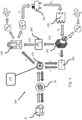
Fig. 1 is an exemplary system of onboard hydrogen production for use in hydrogen fuel cells in a FCEV. -
Fig. 2 is an exemplary view of a hydrogen electrolyzer. -
Fig. 3 is an exemplary view of a hydrogen fuel cell. -
Fig. 4 is a further example of a system of onboard hydrogen production for use in hydrogen fuel cells in a FCEV. -
Fig. 5 is a further example of a system of onboard hydrogen production for use in hydrogen fuel cells in a FCEV. -
Fig. 6 is an exemplary view of the flow of hydrogen, oxygen and water between the one or more hydrogen electrolyzers and the one or more fuel cells in the system. -
Fig. 7 is a further exemplary view of the flow of hydrogen, oxygen and water between the one or more hydrogen electrolyzers and the one or more fuel cells in the system. -
Fig. 8 is a further exemplary view of the flow of hydrogen, oxygen and water between the one or more hydrogen electrolyzers and the one or more fuel cells in the system. -
Fig. 9 is an exemplary view of a FCEV comprising a system of onboard hydrogen production for use in hydrogen fuel cells in a FCEV. - Aspects set forth below represent the necessary information to enable those skilled in the art to practice the disclosure.
- Regenerative braking is an energy recovery mechanism that slows down a moving vehicle by converting its kinetic energy into a form of energy that can be either used immediately or stored until needed. In this mechanism, the electric traction motor uses the vehicle's momentum to recover energy that would otherwise be lost to the brake discs as heat. In a hydrogen fuel cell powered vehicle the transmission of the vehicle is set up such that when the driver applies the brakes, the electric motor reverses itself and applies a resistance to the wheels rather than power. Electric motors, when used in reverse, function as generators and will then convert mechanical energy into electrical energy that can be used to recharge the batteries. In addition to improving the overall efficiency of the vehicle, regeneration can significantly extend the life of the braking system as the mechanical parts will not wear out as quickly.
- However, during the braking or deceleration of the vehicle large amounts of energy is produced in a short instance that cannot be stored in full due to limitation in storage capacity. Thus, a large part of the kinetic energy may still be lost as heat either in the brakes or regenerative resistors. The present document discloses a system and a method of how the kinetic energy generated during deceleration of a vehicle can be utilized in an effective manner in onboard hydrogen production for subsequent use in hydrogen fuel cells to propel the hydrogen-powered FCEV.
- With reference to
Fig. 1 asystem 100 for onboard hydrogen production for use in fuel cells in aFCEV 10 is schematically illustrated. Thesystem 100 includes aregenerative braking system 110, one ormore hydrogen electrolyzers 120, one or morehydrogen storage devices 130, a plurality ofhydrogen fuel cells 140 assembled in one ormore fuel stacks 150, one or moreenergy storage systems 160 and acontroller 170. - The
system 100 includes aregenerative braking system 110 which, when a driver releases the accelerator or presses the brake, reverses the torque of the vehicle's electric motor. This turns the motor into a generator that will convert the mechanical energy transmitted by thewheels 20 to electricity. The generated electricity is advantageously used for powering the one ormore hydrogen electrolysers 120 with electrons for the onboard production of hydrogen from water as explained below. Alternatively, depending on the charging status of theenergy storage system 160, generated electricity may also be used for recharging theenergy storage system 160. - The one or
more hydrogen electrolyzers 120 is configured to generate hydrogen and oxygen from water and electrical energy through electrolysis. Electrolysis is a process wherein electricity is used to split hydrogen atoms in a water molecule apart from the oxygen atom and is performed inside an electrolysis cell in the hydrogen electrolyzer 120 (seeFig. 2 ). The electrolysis cell consists of two electrodes, thecathode 121 and theanode 122 which are separated by apolymer electrolyte membrane 123 surrounded by water. At theanode 122 side, the process decomposes water to produce oxygen and positively charged hydrogen ions (protons). A source of electricity (e.g., from regenerative braking) provides a flow of electrons from theanode 122 through anexternal circuit 124 to thecathode 121, while protons pass through thepolymer electrolyte membrane 123 to thecathode 121. At thecathode 121, the protons recombine with the electrons flowing from theexternal circuit 124 and together, they form hydrogen gas as seen inFig. 2 . The generated hydrogen is advantageously transferred to ahydrogen storage device 130 for subsequent use in the one or morehydrogen fuel cells 140 to produce electricity for propelling theFCEV 10. Advantageously, one ormore hydrogen electrolyzers 120 are assembled together to form one or more stacks of hydrogen electrolyzers (not shown). - The
system 100 comprises one or morehydrogen fuel cells 140 for providing motive power for theFCEV 10. Advantageously, the one or more, such as a plurality ofhydrogen fuel cells 140 is assembled in one or more fuel stacks 150. Thehydrogen fuel cell 140 is advantageously a polymer electrolyte membrane (PEM)fuel cell 140 as seen inFig. 3 . The advantage of using PEM electrolyzers is their ability to operate at high current densities and variable power levels within seconds. This pairs well with vehicular-generated energy such as regenerative braking, where sudden spikes in energy input would otherwise result in uncaptured energy. - In the
PEM fuel cell 140, apolymer electrolyte membrane 143 is sandwiched between acathode 141 and ananode 142. Hydrogen is introduced to theanode 142, and oxygen (or air) is introduced to thecathode 141. At theanode 122 the hydrogen molecules break apart into positively charged protons and negatively charged electrons due to an electrochemical reaction in thehydrogen fuel cell 140. The positively charged protons travel through thepolymer electrolyte membrane 143 to thecathode 141, while the negatively charged electrons are forced to travel through anexternal circuit 144 to thecathode 121 creating electrical current (e.g., providing power to the FCEV 10). The electrons then recombine with the protons and oxygen at thecathode 141 to form water that will leave the cell as can be seen inFig. 3 . - The electricity generating process taking place in the
PEM fuel cell 140 is a reverse reaction of the chemical reaction taking place in thehydrogen electrolyzer 120. Electrolysis is the process which converts electricity into hydrogen, while fuel cells convert the hydrogen back to electricity. The two chemical reactions taking place in ahydrogen fuel cell 140 are the following:
Reaction at the anode 142: 2H2→ 4H+ + 4e-.
Reaction at the cathode 141: O2 + 4H+ + 4e-→ 2H2O.
- The two chemical reactions taking place in the hydrogen electrolyzer are the following:
Reaction at the anode 122: 2H2O → O2 + 4H+ + 4e-
Reaction at the cathode 121: 4H+ + 4e- → 2H2.
- A single hydrogen fuel cell produces less than 1 V, which is insufficient for most applications and therefore the plurality, such as two to more than several hundred
hydrogen fuel cells 140, is assembled into fuel cell stacks 150. - The
system 100 further includes anenergy storage system 160 such as e.g., a battery. Even thoughhydrogen FCEVs 10 produce their own electricity through their hydrogen-powered fuel cells, it's still necessary that a buffer be in place in the form of a high-voltage battery. The battery is advantageously used for recapturing excess vehicular-generated electricity such as e.g., braking energy generated by theregenerative braking system 110, and will provide extra power during short acceleration events, as well as to smooth out the power delivered from the fuel cell. - Water for the generation of hydrogen fuel in the one or
more hydrogen electrolyzers 120 is provided from water stored in awater storage device 180 onboard theFCEV 10. The water is advantageously collected from water vapor produced during the reverse electrolysis in the PEMfuel cell stack 150 during the generation of electricity from hydrogen. This is very valuable since the water generated in this process is very pure and will not need further purification. The generated water is collected from thefuel cell stack 150 and stored in awater storage device 180 until needed for hydrogen production in thehydrogen electrolyzer 120. The water may also be provided from other sources such as e.g., an onboard condenser and/or evaporator in an air-conditioning system, on-board rainwater collectors. It may also be provided from the atmosphere by adsorption onto hygroscopic materials or provided from an external water tap. However, water provided from these sources may require purification or filtering before being added to thewater storage device 180. - Temperature is an important variable in the electrolysis reaction since efficiency in hydrogen production increases with increasing temperatures.
Advantageously hydrogen electrolyzers 120 operate at about 70°-95°C. Under standard conditions i.e., a temperature of 273.15 K (0 °C, 32 °F) and an absolute pressure of 105 Pa (100 kPa, 1 bar),
the enthalpy required for the decomposition of water is 285.9 kJ/mol. A portion of the required energy for a sustained electrolysis reaction is supplied by thermal energy and the remainder is supplied through electrical energy. Thus, the total energy demand for water electrolysis is the sum of electrical and heat energy demands. The higher the temperature of the reaction, the lower the electrical energy demands in the production of hydrogen. To raise the reaction rate of hydrogen production in thehydrogen electrolyzer 120, thesystem 100 includes acontroller 170 configured to direct surplus heat generated by heat emitting components in theFCEV 10 to the one ormore hydrogen electrolyzers 120. -
FCEVs 10 do not have a combustion engine to generate heat, so heat must come from other sources. Once theFCEV 10 is up and running, the electrochemical reactions in thePEM fuel cells 140 generate a large amount of heat along with the electricity and water. For better efficiency and consistence output of thefuel cell stack 150, there must be a cooling process either by air or fluid to get rid of the fuel cell-generated heat. By means of a shared cooling system, this heat is advantageously transferred to other components within the FCEV which require warming. Besides thehydrogen electrolyzer 120, thewater storage tank 180, and the inlet manifolds of thehydrogen storage 130 may benefit from heat supplied by heat emitting components. Brake resistors, radiators, air-conditioning units, theenergy storage system 160, onboard chargers and power converters (DC-DC) are further components that may all generate heat during propulsion of theFCEV 10. Thecontroller 170 in charge of the shared cooling system will direct at least some of the dissipated heat from these components to thehydrogen electrolyzer 120 to improve the reaction rate of hydrogen production. - Sensors may be provided to monitor the temperature in different components of the FCEV, and different control methods or artificial intelligence used to direct heating or cooling as required. The
controller 170 may comprise a computing device such as a dedicated microprocessor or electronic control unit (ECU) operating in accordance with instructions from appropriate control software. Thecontroller 170 may comprise one or more processors, one or more memories and one or more network interfaces. As should be appreciated, all of these components communicate with each other over a communication bus. - The generated hydrogen is stored on board the
FCEV 10 in one or morehydrogen storage devices 130. Thehydrogen storage device 130 may be either a chemical or compressed storage device of the type known in the art. Somehydrogen electrolyzers 120 such as e.g., PEM electrolyzers may deliver hydrogen at about 30 bar without a compressor. Thereafter the gas needs to be compressed to about 700 bar for passenger vehicles, and 300-350 bar for trucks and buses. Thesystem 100 advantageously comprises acompressor 135 configured to convert the low-pressure hydrogen generated by thehydrogen electrolyzer 120 to high-pressure hydrogen that can be stored in the one or more hydrogen storage devices 130 (seeFig. 4 ). - Excess vehicular-generated electrical energy for powering the
hydrogen electrolyzer 120 to generate hydrogen may also be obtained from a solarenergy harvesting device 190 such as e.g., a solar panel and/or an array of solar panels provided on the exterior such as e.g., the roof or other exposed surfaces of theFCEV 10. The solarenergy harvesting device 190 generates free electricity while the FCEV is parked or driving outdoors and exposed to sunlight (seeFig. 5 ). Alternatively, depending on the charging status of theenergy storage system 160, generated electricity from the solarenergy harvesting device 190 may also be used for recharging the energy storage system. The advantage of using the solar generated energy to power thehydrogen electrolyzer 120, rather than using the sun's energy directly to propel theFCEV 10, is that hydrogen can be generated and collected in thehydrogen storage device 130 during daytime when the sun is shining and then used for driving thehydrogen fuel cell 140 at night. - Advantageously, excess vehicular-generated electrical energy for powering the
hydrogen electrolyzer 120 to generate hydrogen may be provided both by a solarenergy harvesting device 190 and regenerative braking as seen inFig. 5 . - In one example of the
system 100 described herein, oxygen required for energy production by the PEMfuel cell stack 150, is obtained from surrounding air as seen inFigs. 1 ,3 and6 . In this example the PEMfuel cell stack 150 obtains hydrogen gas from thehydrogen storage device 130 which is introduced to theanode 141, and oxygen from air introduced to thecathode 142. The hydrogen gas breaks apart to form protons and electrons. While the protons travel across thepolymer electrolyte membrane 143 to thecathode 142, the electrons are forced to travel through anexternal circuit 144 to perform work (providing power to the FCEV 10) and then recombine with the protons on thecathode 142 side where the protons, electrons, and oxygen molecules combine to form water. Water is stored in thewater storage device 180. - During the hydrogen electrolyzis reaction in the
hydrogen electrolyzer 120, electricity provided from vehicular-generated electricity (e.g., due to input from regenerative braking and/or solar energy) is directed to thecathode 121 of thehydrogen electrolyzer 120. Water obtained from thewater storage device 180 is provided to theanode 122 where it is split into oxygen and protons. The protons travel across thepolymer electrolyte membrane 123 to thecathode 121 where they combine with the protons to form hydrogen gas. The hydrogen gas is stored in thehydrogen storage device 130 while oxygen is expelled into the surrounding air as seen inFig. 6 . - In an alternative example, the
system 100 may advantageously include anoxygen storage device 185 wherein oxygen produced by thehydrogen electrolyzer 120 during hydrogen production can be stored. In this example oxygen may instead of being dissipated to the surrounding air during the electrolysis reaction, be collected in anoxygen storage device 185 and used directly by the PEM fuel cell during the energy production (seeFig. 7 ). This is advantageous since oxygen produced by the electrolyzer is very pure and will not require any purification before being transmitted to the PEM fuel cell. Furthermore, oxygen may be stored at a much higher concentration in anoxygen storage device 185, compared to the concentration of about 20% supplied from the air. - As mentioned above, the reactions that take place in a
hydrogen electrolyzer 120 are very similar to the reaction in ahydrogen fuel cell 140, except that the reactions that occur in the anode and cathode are reversed. In ahydrogen fuel cell 140, theanode 141 is where hydrogen gas is consumed (seeFig. 3 ), and in ahydrogen electrolyzer 120, the hydrogen gas is produced at the cathode 122 (seeFig. 2 ). APEM electrolyzer 120 uses the same type of polymer electrolyte membrane as aPEM fuel cell 140. The hydrogen produced from aPEM electrolyzer cell 120 is perfect for use in PEMhydrogen fuel cells 140 since hydrogen produced by this type of electrolyzer is of high purity. In an advantageous embodiment thePEM fuel cells 140 may operate both asPEM fuel cells 140 andPEM electrolyzers 120 depending on demand. - The dual use of
PEM fuel cells 140 is very advantageous since separatehydrogen electrolyzer units 120 performing only hydrogen electrolysis can be omitted from thesystem 100. Instead, a controller may allocate what type of reaction each unit is required to perform depending on demand at a given time. This dual operation of PEM fuel cells/stacks 140/150 is illustrated inFig. 8 . In situations when vehicular-generated electricity is available in excess (e.g., due to input from regenerative braking and/or solar energy), the PEM fuel cells/stacks 140/150 may switch to water decomposition by means of the electrolysis process to generate hydrogen that may be stored for later use. The PEM fuel cells switches to the electrolysis mode to withdraw water from thewater storage device 180 and utilizes the vehicular-generated electricity to generate hydrogen and oxygen which are advantageously stored in hydrogen andoxygen storage devices - When electricity is in high demand such as e.g., during propulsion of the
FCEV 10, the PEM fuel cells/stacks 140/150 switch to withdrawing hydrogen and oxygen from the hydrogen andoxygen storage devices water storage device 180. It should be noted that the PEM fuel cell/stack 140/150 may not perform the different reactions simultaneously. It either performs the electrolysis reaction or the energy production reaction. - A method for onboard hydrogen production for use in
hydrogen fuel cells 140 in aFCEV 10 will now be described. The method includes transferring vehicular-generated electrical energy produced by theFCEV 10 during regenerative braking and/or decent to thehydrogen electrolyzer 120. During regenerative braking of theFCEV 10, any deceleration of thewheels 20 on theFCEV 10 e.g., during braking or descent of a hill, will reverse the torque of the vehicle's electric motor turning the motor into agenerator 110 that will convert mechanical energy transmitted by thewheels 20 to electricity. This vehicular-generated energy is advantageously transferred to the one ormore hydrogen electrolyzers 120 provided onboard theFCEV 10. - The method includes providing water obtained from operation of one or more
hydrogen fuel cells 140 during generation of electricity from hydrogen to thehydrogen electrolyzer 120. Advantageously, water generated during operation of one or morehydrogen fuel cells 140 to generate electricity from hydrogen and oxygen is collected in the onboardwater storage device 180. Water collected fromhydrogen fuel cells 140, such as PEM fuel cells, is very pure and requires no further purification. However, water may also be collected from air-conditioning devices or from onboard rainwater collectors and thereafter subjected to filtering and/or further purification before being added to thewater storage device 180. The collected water is transferred from thewater storage device 180 to the one ormore hydrogen electrolyzers 120 by means of e.g., a pumping device (not shown). - Hydrogen is generated by means of electrolysis in the
hydrogen electrolyzer 120 from water provided from thewater storage device 180 and vehicular-generated electrical energy. Electricity provided from vehicular-generated electricity (e.g., due to deceleration of the wheels on the FCEV 10) is directed to thecathode 121 of thehydrogen electrolyzer 120. Water obtained from thewater storage device 180 is provided to theanode 122 in the electrolysis cell where it is split into oxygen and protons (seeFig. 2 ). The protons travel across themembrane 123 to thecathode 121 where they combine with the vehicular generated electrons to form hydrogen gas and oxygen. The hydrogen gas generated by thehydrogen electrolyzer 120 is thereafter collected in ahydrogen storage device 130. - The method also includes directing surplus heat generated by heat-emitting components in the
FCEV 10 to the one ormore hydrogen electrolyzers 120. Acontroller 170 is configured to direct heat emitted by the heat-emitting components such as heat dissipating from the energy storage system (batteries) 160, hydrogen fuel cells/stacks 140/150, radiators, heaters, power converters and the electric motor, during operation of theFCEV 10. The added thermal energy improves the rate of the electrolysis reaction in the one ormore hydrogen electrolyzers 120. - The hydrogen stored in the
hydrogen storage device 130 is thereafter advantageously used in the generation of electrical energy and water by means of the one or more hydrogen fuel cells/stacks 140/150. Any water generated in this process is advantageously collected in thewater storage device 180 for subsequent use during electrolysis in thehydrogen electrolyzer 120. - Vehicular-generated electrical energy is often generated in large amounts only during a short time span. The
controller 170 may be configured to preferably direct the regenerated electrical energy produced by theFCEV 10 during braking and/or decent either to the one ormore hydrogen electrolyzers 120 to generate hydrogen, or alternately to anenergy storage system 160 not fully charged. - The method may further include transferring electrical energy obtained from a solar
energy harvesting device 190 such as e.g., a solar panel and/or array of solar panels provided on the exterior of theFCEV 10 to thehydrogen electrolyzer 120. Solarenergy harvesting devices 190 are advantageously arranged on the roof or other exposed surfaces of thevehicle 10 and may generate free electricity while the FCEV is parked or driving outdoors and exposed to sunlight. The electrical energy generated by the solarenergy harvesting device 190 is advantageously transferred directly to the one ormore hydrogen electrolyzers 120 for generation of hydrogen gas as described above. Alternatively, depending on the charging status theenergy storage system 160, generated electricity from the solarenergy harvesting device 190 may also be used for recharging theenergy storage system 160. Advantageously, the vehicular-generated electrical energy for powering thehydrogen electrolyzer 120 to generate hydrogen may be provided both by a solarenergy harvesting device 190 and regenerative braking as seen inFig. 5 . - The method may further include transferring the hydrogen gas generated by the one or
more hydrogen electrolyzers 120 to acompressor 135 configured to convert low-pressure hydrogen gas to high-pressure hydrogen gas for storage in thehydrogen storage device 130 until further use in the one or morehydrogen fuel cells 140. - The terminology used herein is for the purpose of describing particular aspects only and is not intended to be limiting of the disclosure. As used herein, the singular forms "a," "an," and "the" are intended to include the plural forms as well, unless the context clearly indicates otherwise. As used herein, the term "and/or" includes any and all combinations of one or more of the associated listed items. It will be further understood that the terms "comprises," "comprising," "includes," and/or "including" when used herein specify the presence of stated features, integers, steps, operations, elements, and/or components, but do not preclude the presence or addition of one or more other features, integers, steps, operations, elements, components, and/or groups thereof.
- It will be understood that, although the terms first, second, etc., may be used herein to describe various elements, these elements should not be limited by these terms. These terms are only used to distinguish one element from another. For example, a first element could be termed a second element, and, similarly, a second element could be termed a first element without departing from the scope of the present disclosure.
- Relative terms such as "below" or "above" or "upper" or "lower" or "horizontal" or "vertical" may be used herein to describe a relationship of one element to another element as illustrated in the Figures. It will be understood that these terms and those discussed above are intended to encompass different orientations of the device in addition to the orientation depicted in the Figures. It will be understood that when an element is referred to as being "connected" or "coupled" to another element, it can be directly connected or coupled to the other element, or intervening elements may be present. In contrast, when an element is referred to as being "directly connected" or "directly coupled" to another element, there are no intervening elements present.
- Unless otherwise defined, all terms (including technical and scientific terms) used herein have the same meaning as commonly understood by one of ordinary skill in the art to which this disclosure belongs. It will be further understood that terms used herein should be interpreted as having a meaning consistent with their meaning in the context of this specification and the relevant art and will not be interpreted in an idealized or overly formal sense unless expressly so defined herein.
- It is to be understood that the present disclosure is not limited to the aspects described above and illustrated in the drawings; rather, the skilled person will recognize that many changes and modifications may be made within the scope of the present disclosure and appended claims. In the drawings and specification, there have been disclosed aspects for purposes of illustration only and not for purposes of limitation, the scope of the inventive concepts being set forth in the following claims.
Claims (15)
- A system (100) for onboard hydrogen production for use in hydrogen fuel cells (140) in a fuel cell electrical vehicle (10), the system (100) comprising- a regenerative braking system (110) configured to converting mechanical energy to electrical energy;- one or more hydrogen electrolyzers (120) configured to generate hydrogen and oxygen from water and electrical energy;- one or more hydrogen fuel cells (140) configured to generate electrical energy and water from hydrogen;- one or more energy storage systems (160) for storing electrical energy generated by the regenerative braking system (110) and/or the one or more hydrogen fuel cells (140);- one or more hydrogen storage devices (130) for storing hydrogen generated by the hydrogen electrolyzer;- a controller (170) for directing surplus heat generated by heat emitting components in the fuel cell electrical vehicle (10) to the one or more hydrogen electrolyzers (120).
- The system (100) according to claim 1, wherein the system (100) further includes a solar energy harvesting system provided on an exterior of the fuel cell electrical vehicle (10).
- The system (100) according to claims 1 and 2, wherein the one or more hydrogen electrolyzers (120) is one or more proton exchange membrane (PEM) electrolyzers assembled into a (PEM) fuel cell stack (150).
- The system (100) according to any one of the preceding claims, wherein the system (100) further includes a water storage device (180) for storing water generated by the one or more hydrogen fuel cells (140).
- The system (100) according to any one of the preceding claims, wherein the system (100) further includes a compressor (135) configured to convert low-pressure oxygen to high-pressure hydrogen for storage in the hydrogen storage device (130).
- The system (100) according to any one of the preceding claims, wherein heat emitting components are selected from the group consisting of the energy storage system (160), hydrogen fuel cells (140), brake resistors, radiators, heaters, power converters and the electric motor.
- The system (100) according to any one of the preceding claims, wherein the system (100) further includes an oxygen storage device (185) for storing oxygen generated by the one or more hydrogen electrolyzers (120).
- The system (100) according to any one of the preceding claims, wherein the one or more hydrogen fuel cells (140) is configured to operate as hydrogen electrolyzers (120) generating hydrogen and oxygen from water.
- A fuel cell electrical vehicle (10) comprising the system (100) for onboard hydrogen production according to any one of the claims 1-8.
- A method for onboard hydrogen production for use in fuel cells in a fuel cell electric vehicle (10), wherein the method comprises- transferring vehicular-generated electrical energy produced by a regenerative braking system (110) during braking and/or decent of the fuel cell electrical vehicle (10) to one or more hydrogen electrolyzers (120); and- providing the one or more hydrogen electrolyzers (120) with water obtained from operation of one or more hydrogen fuel cells (140) during generation of electricity from hydrogen; and- generating hydrogen by means of the one or more hydrogen electrolyzers (120) from water and the vehicular-generated electrical energy; and- directing heat emitted during operation of the fuel cell electrical vehicle (10) to the one or more hydrogen electrolyzers (120) for accelerating production of hydrogen gas by the one or more hydrogen electrolyzers (120); and- collecting generated hydrogen in a hydrogen storage device (130).
- The method according to claim 10, further comprising transferring electrical energy obtained from a solar energy harvesting device (190) provided on the exterior of the fuel cell electrical vehicle (10) to one or more of the hydrogen electrolyzers (120).
- The method according to any one of the preceding claims 10-11, wherein hydrogen gas generated by the hydrogen electrolyzer (120) is transferred to a compressor (135) to convert low-pressure hydrogen gas to high-pressure hydrogen gas to be stored in the hydrogen storage device (130) until use in the one or more hydrogen fuel cells (140).
- The method according to any one of the preceding claims 10-12, wherein the method further comprises transferring water obtained during generation of electrical energy by the one or more hydrogen fuel cells (140) to a water storage device (180) for subsequent use by the one or more hydrogen electrolyzers (120) during generation of hydrogen.
- The method according to any one of the preceding claims 10-13, wherein oxygen generated by the one or more hydrogen electrolyzers (120) is transferred to an onboard oxygen storage device (185) for use in the one or more hydrogen fuel cells (140) for generation of electricity from hydrogen.
- The method according to any one of the preceding claims 10-14, wherein the one or more hydrogen fuel cells (140) operate as hydrogen electrolyzers (120) generating hydrogen and oxygen from water.
Priority Applications (2)
| Application Number | Priority Date | Filing Date | Title |
|---|---|---|---|
| EP23165840.2A EP4438382A1 (en) | 2023-03-31 | 2023-03-31 | Fuel cell as an electrolyzer in fuel cell electric vehicles for onboard hydrogen production |
| US18/613,329 US20240332579A1 (en) | 2023-03-31 | 2024-03-22 | Fuel cell as an electrolyzer in fuel cell electric vehicles for onboard hydrogen production |
Applications Claiming Priority (1)
| Application Number | Priority Date | Filing Date | Title |
|---|---|---|---|
| EP23165840.2A EP4438382A1 (en) | 2023-03-31 | 2023-03-31 | Fuel cell as an electrolyzer in fuel cell electric vehicles for onboard hydrogen production |
Publications (1)
| Publication Number | Publication Date |
|---|---|
| EP4438382A1 true EP4438382A1 (en) | 2024-10-02 |
Family
ID=85795382
Family Applications (1)
| Application Number | Title | Priority Date | Filing Date |
|---|---|---|---|
| EP23165840.2A Pending EP4438382A1 (en) | 2023-03-31 | 2023-03-31 | Fuel cell as an electrolyzer in fuel cell electric vehicles for onboard hydrogen production |
Country Status (2)
| Country | Link |
|---|---|
| US (1) | US20240332579A1 (en) |
| EP (1) | EP4438382A1 (en) |
Citations (3)
| Publication number | Priority date | Publication date | Assignee | Title |
|---|---|---|---|---|
| EP0755088A2 (en) * | 1995-07-21 | 1997-01-22 | Railway Technical Research Institute | Regenerative power system |
| US20070138006A1 (en) * | 2005-12-21 | 2007-06-21 | Oakes Thomas W | System and Method for Generating Hydrogen Gas |
| WO2012026219A1 (en) * | 2010-08-25 | 2012-03-01 | コニカミノルタホールディングス株式会社 | Secondary battery type fuel cell system |
-
2023
- 2023-03-31 EP EP23165840.2A patent/EP4438382A1/en active Pending
-
2024
- 2024-03-22 US US18/613,329 patent/US20240332579A1/en active Pending
Patent Citations (3)
| Publication number | Priority date | Publication date | Assignee | Title |
|---|---|---|---|---|
| EP0755088A2 (en) * | 1995-07-21 | 1997-01-22 | Railway Technical Research Institute | Regenerative power system |
| US20070138006A1 (en) * | 2005-12-21 | 2007-06-21 | Oakes Thomas W | System and Method for Generating Hydrogen Gas |
| WO2012026219A1 (en) * | 2010-08-25 | 2012-03-01 | コニカミノルタホールディングス株式会社 | Secondary battery type fuel cell system |
Also Published As
| Publication number | Publication date |
|---|---|
| US20240332579A1 (en) | 2024-10-03 |
Similar Documents
| Publication | Publication Date | Title |
|---|---|---|
| Appleby | The electrochemical engine for vehicles | |
| US8153309B2 (en) | Apparatus and method using hydrogen pressure in fuel cell electric vehicle | |
| US6459231B1 (en) | Power device | |
| US7147072B2 (en) | Method and apparatus for providing hybrid power in vehicle | |
| CN104934620B (en) | Integrated solar-powered high-pressure hydrogen production and batter-charghing system | |
| CN1689185A (en) | System and method for recharging a metal-air converter used for vehicle propulsion | |
| EP0755088A3 (en) | Regenerative power system | |
| JP2014074207A (en) | Renewable energy storage system | |
| CN203601032U (en) | Fuel cell and solar energy combined supply electric automobile | |
| CN104627015A (en) | Energy management system of new type fuel cell hybrid electric vehicle | |
| CN100459268C (en) | Hydrogen storage based rechargeable fuel cell system | |
| Colmenar-Santos et al. | Residual heat use generated by a 12 kW fuel cell in an electric vehicle heating system | |
| CN104627002A (en) | Fuel battery and solar energy combined supply type electric vehicle | |
| EP0406831B1 (en) | High power density regenerative fuelcell for peak power | |
| Ren et al. | Review of energy storage technologies for extended range electric vehicle | |
| KR20160015070A (en) | System for fuel cell vehicle | |
| US20030082424A1 (en) | Vehicle having an energy store, and a method for operating the vehicle | |
| US20240332579A1 (en) | Fuel cell as an electrolyzer in fuel cell electric vehicles for onboard hydrogen production | |
| KR20090058047A (en) | Regenerative braking control method of electric vehicle | |
| KR20240042845A (en) | Fuel cell vehicle control system and method therefor | |
| Andari et al. | Optimization of hydrogen consumption for fuel cell hybrid vehicle | |
| CN221366678U (en) | Power system of vehicle and vehicle | |
| DE202018005150U1 (en) | Electric vehicle with fuel cell and battery | |
| EP4610397A1 (en) | In-vehicle hydrogen generation and storage system for hydrogen (fuel cell electric vehicle) powered transport vehicles | |
| Pandolfo | Design of a PEMFC thermal management system in heavy-duty vehicle application |
Legal Events
| Date | Code | Title | Description |
|---|---|---|---|
| PUAI | Public reference made under article 153(3) epc to a published international application that has entered the european phase |
Free format text: ORIGINAL CODE: 0009012 |
|
| STAA | Information on the status of an ep patent application or granted ep patent |
Free format text: STATUS: THE APPLICATION HAS BEEN PUBLISHED |
|
| AK | Designated contracting states |
Kind code of ref document: A1 Designated state(s): AL AT BE BG CH CY CZ DE DK EE ES FI FR GB GR HR HU IE IS IT LI LT LU LV MC ME MK MT NL NO PL PT RO RS SE SI SK SM TR |
|
| STAA | Information on the status of an ep patent application or granted ep patent |
Free format text: STATUS: REQUEST FOR EXAMINATION WAS MADE |
|
| 17P | Request for examination filed |
Effective date: 20250325 |