EP4438228A1 - Shaft alignment device and shaft alignment program - Google Patents
Shaft alignment device and shaft alignment program Download PDFInfo
- Publication number
- EP4438228A1 EP4438228A1 EP24166175.0A EP24166175A EP4438228A1 EP 4438228 A1 EP4438228 A1 EP 4438228A1 EP 24166175 A EP24166175 A EP 24166175A EP 4438228 A1 EP4438228 A1 EP 4438228A1
- Authority
- EP
- European Patent Office
- Prior art keywords
- shaft alignment
- mark
- captured image
- eyeglasses lens
- printed
- Prior art date
- Legal status (The legal status is an assumption and is not a legal conclusion. Google has not performed a legal analysis and makes no representation as to the accuracy of the status listed.)
- Pending
Links
Images




Classifications
-
- B—PERFORMING OPERATIONS; TRANSPORTING
- B24—GRINDING; POLISHING
- B24B—MACHINES, DEVICES, OR PROCESSES FOR GRINDING OR POLISHING; DRESSING OR CONDITIONING OF ABRADING SURFACES; FEEDING OF GRINDING, POLISHING, OR LAPPING AGENTS
- B24B9/00—Machines or devices designed for grinding edges or bevels on work or for removing burrs; Accessories therefor
- B24B9/02—Machines or devices designed for grinding edges or bevels on work or for removing burrs; Accessories therefor characterised by a special design with respect to properties of materials specific to articles to be ground
- B24B9/06—Machines or devices designed for grinding edges or bevels on work or for removing burrs; Accessories therefor characterised by a special design with respect to properties of materials specific to articles to be ground of non-metallic inorganic material, e.g. stone, ceramics, porcelain
- B24B9/08—Machines or devices designed for grinding edges or bevels on work or for removing burrs; Accessories therefor characterised by a special design with respect to properties of materials specific to articles to be ground of non-metallic inorganic material, e.g. stone, ceramics, porcelain of glass
- B24B9/14—Machines or devices designed for grinding edges or bevels on work or for removing burrs; Accessories therefor characterised by a special design with respect to properties of materials specific to articles to be ground of non-metallic inorganic material, e.g. stone, ceramics, porcelain of glass of optical work, e.g. lenses, prisms
- B24B9/146—Accessories, e.g. lens mounting devices
-
- B—PERFORMING OPERATIONS; TRANSPORTING
- B24—GRINDING; POLISHING
- B24B—MACHINES, DEVICES, OR PROCESSES FOR GRINDING OR POLISHING; DRESSING OR CONDITIONING OF ABRADING SURFACES; FEEDING OF GRINDING, POLISHING, OR LAPPING AGENTS
- B24B13/00—Machines or devices designed for grinding or polishing optical surfaces on lenses or surfaces of similar shape on other work; Accessories therefor
- B24B13/005—Blocking means, chucks or the like; Alignment devices
- B24B13/0055—Positioning of lenses; Marking of lenses
-
- B—PERFORMING OPERATIONS; TRANSPORTING
- B24—GRINDING; POLISHING
- B24B—MACHINES, DEVICES, OR PROCESSES FOR GRINDING OR POLISHING; DRESSING OR CONDITIONING OF ABRADING SURFACES; FEEDING OF GRINDING, POLISHING, OR LAPPING AGENTS
- B24B47/00—Drives or gearings; Equipment therefor
- B24B47/22—Equipment for exact control of the position of the grinding tool or work at the start of the grinding operation
- B24B47/225—Equipment for exact control of the position of the grinding tool or work at the start of the grinding operation for bevelling optical work, e.g. lenses
-
- B—PERFORMING OPERATIONS; TRANSPORTING
- B24—GRINDING; POLISHING
- B24B—MACHINES, DEVICES, OR PROCESSES FOR GRINDING OR POLISHING; DRESSING OR CONDITIONING OF ABRADING SURFACES; FEEDING OF GRINDING, POLISHING, OR LAPPING AGENTS
- B24B49/00—Measuring or gauging equipment for controlling the feed movement of the grinding tool or work; Arrangements of indicating or measuring equipment, e.g. for indicating the start of the grinding operation
- B24B49/12—Measuring or gauging equipment for controlling the feed movement of the grinding tool or work; Arrangements of indicating or measuring equipment, e.g. for indicating the start of the grinding operation involving optical means
-
- B—PERFORMING OPERATIONS; TRANSPORTING
- B24—GRINDING; POLISHING
- B24B—MACHINES, DEVICES, OR PROCESSES FOR GRINDING OR POLISHING; DRESSING OR CONDITIONING OF ABRADING SURFACES; FEEDING OF GRINDING, POLISHING, OR LAPPING AGENTS
- B24B9/00—Machines or devices designed for grinding edges or bevels on work or for removing burrs; Accessories therefor
- B24B9/02—Machines or devices designed for grinding edges or bevels on work or for removing burrs; Accessories therefor characterised by a special design with respect to properties of materials specific to articles to be ground
- B24B9/06—Machines or devices designed for grinding edges or bevels on work or for removing burrs; Accessories therefor characterised by a special design with respect to properties of materials specific to articles to be ground of non-metallic inorganic material, e.g. stone, ceramics, porcelain
- B24B9/08—Machines or devices designed for grinding edges or bevels on work or for removing burrs; Accessories therefor characterised by a special design with respect to properties of materials specific to articles to be ground of non-metallic inorganic material, e.g. stone, ceramics, porcelain of glass
- B24B9/14—Machines or devices designed for grinding edges or bevels on work or for removing burrs; Accessories therefor characterised by a special design with respect to properties of materials specific to articles to be ground of non-metallic inorganic material, e.g. stone, ceramics, porcelain of glass of optical work, e.g. lenses, prisms
- B24B9/148—Machines or devices designed for grinding edges or bevels on work or for removing burrs; Accessories therefor characterised by a special design with respect to properties of materials specific to articles to be ground of non-metallic inorganic material, e.g. stone, ceramics, porcelain of glass of optical work, e.g. lenses, prisms electrically, e.g. numerically, controlled
Definitions
- the present disclosure relates to a shaft alignment device used in a process of processing a peripheral edge of an eyeglasses lens, and a shaft alignment program used in the shaft alignment device.
- a cup attachment device that attaches a processing jig (cup) to an eyeglasses lens is known (see JP2020-038268A ).
- the eyeglasses lens is a progressive lens
- images of hidden marks and printed marks are taken in the process of setting the attachment position (shaft alignment position) of the cup with respect to the progressive lens.
- a technical object of the present invention is to provide a shaft alignment device and a shaft alignment program that enable to appropriately set a shaft alignment position of an eyeglasses lens.
- a shaft alignment device used in a process of processing a peripheral edge of an eyeglasses lens including:
- the shaft alignment device according to the above-described (6 )or (7), in which the captured image of the eyeglasses lens is an entire image of the eyeglasses lens, and includes at least one of both the first printed mark and the second printed mark and both the first hidden mark and the second hidden mark.
- a shaft alignment program of a shaft alignment device used in a process of processing a peripheral edge of an eyeglasses lens including instructions which, when executed by a controller of the shaft alignment device, cause the shaft alignment device to perform:
- the shaft alignment device of the present embodiment may be a shaft alignment device used in the process of processing the peripheral edge of an eyeglasses lens.
- the shaft alignment device may be a shaft alignment device including a shaft alignment position setting means that sets a shaft alignment position of a holding means that pinches the eyeglasses lens to hold the eyeglasses lens.
- the holding means may be a holding means (for example, a chuck shaft) included in an eyeglasses lens peripheral edge processing device.
- the shaft alignment device may be a cup attachment device including a cup attachment means that attaches a cup, which is a processing jig for holding the eyeglasses lens in the holding means.
- the shaft alignment device of the present embodiment may include a cup attachment means (for example, a cup attachment mechanism 30).
- the cup attachment means may attach a cup, which is a processing jig for holding the eyeglasses lens to the holding means, to the eyeglasses lens based on the shaft alignment position set by the shaft alignment position setting means (details will be described later).
- the cup attachment means may attach the cup to at least one of the front surface and rear surface of the eyeglasses lens.
- the shaft alignment device of the present embodiment may include an imaging means (for example, an eyeglasses lens measurement mechanism 40).
- the imaging means may capture a captured image of a lens surface of the eyeglasses lens.
- the imaging means may have an imaging range capable of imaging a wide range of the lens surface of the eyeglasses lens.
- the imaging means may have an imaging range capable of taking the entire lens surface of the eyeglasses lens.
- a captured image of an eyeglasses lens is the entire image of the eyeglasses lens, and may include at least one of both the left and right printed marks (first printed mark and second printed mark) put on the eyeglasses lens and both the left and right hidden marks (first hidden mark and second hidden mark) put on the eyeglasses lens.
- the axis degree of the left and right printed marks or the left and right hidden marks with respect to the center position (for example, geometric center position) of the eyeglasses lens can be easily understood.
- the imaging means may include an imaging optical system (for example, an imaging optical system 420) as a part of the imaging means.
- the imaging optical system may image the eyeglasses lens by receiving reflected light flux of natural light from the eyeglasses lens.
- the imaging optical system may image the eyeglasses lens by receiving a reflected light flux from the eyeglasses lens by the illumination optical system (for example, an illumination optical system 410).
- the imaging means may have at least an imaging element.
- the shaft alignment device of the present embodiment may include a detection means (for example, a control unit 60).
- the detection means may detect a specific part based on a captured image taken by the imaging means.
- the detection means may detect the specific part by analyzing the captured image based on the captured image of the eyeglasses lens.
- various image processing methods may be applied to the captured image analysis processing.
- the specific part may be detected by detecting a change in at least one of the luminance value, saturation, hue, and the like of the captured image.
- the specific part may be detected by using a template image of the specific part prepared in advance and calculating the degree of similarity between the template image and the captured image.
- the detection means may detect the left and right printed marks of the eyeglasses lens as specific parts from the captured image.
- the detection means may also serve as a printed mark detection means, which will be described later.
- the detection means may detect the left and right hidden marks of the eyeglasses lens as specific parts from the captured image.
- the detection means may also serve as a hidden mark detection means, which will be described later. It is needless to say that, for example, the detection means may detect both the left and right printed marks and the left and right hidden marks of the eyeglasses lens as specific parts from the captured image.
- the shaft alignment device of the present embodiment may include an area setting means (for example, the control unit 60).
- the area setting means may set a specific area of the captured image taken by the imaging means. For example, by this manner, the operator can easily set a desired specific part of the eyeglasses lens as a specific area, and as a result, it is possible to easily acquire a locally enlarged image that includes the specific part of the eyeglasses lens desired by the operator.
- the area setting means may set any position input by the operation of the operator of the operation means as the specific area.
- the shaft alignment device may include an operation means (for example, a monitor 2) through which an operator inputs an operation signal for specifying a specific area, and the area setting means may set the position specified on the captured image by the operation means as the specific area.
- the area setting means may set a specific area including the specific part detected by the detection means.
- the area setting means may set a predetermined area based on the specific area as the specific area.
- the area setting means may set a specific area including at least one of one first printed mark and the other second printed mark of the eyeglasses lens as the specific area including the specific part detected by the detection means (the printed mark detection means).
- the area setting means may set one specific area that includes both the first printed mark and the second printed mark, or may set two specific areas for each of the first printed mark and the second printed mark.
- the area setting means may set a specific area including at least one of one first hidden mark and the other second hidden mark of the eyeglasses lens as the specific area including the specific part detected by the detection means (the hidden mark detection means).
- the area setting means may set one specific area that includes both the first hidden mark and the second hidden mark, or may set two specific areas for each of the first hidden mark and the second hidden mark.
- the area setting means may respectively set a first specific area including at least one of the first printed mark or the first hidden mark, and a second specific area including at least one of the second printed mark or the second hidden mark.
- the area setting means may set a predetermined area in an imaging area of the captured image taken by the imaging means as the specific area.
- the area set in advance in the imaging area of the captured image may be an area set in advance by associating the area with a predetermined coordinate position with respect to the captured image. For example, by this manner, a locally enlarged image of the eyeglasses lens can be easily acquired without the operator specifying a desired specific part of the eyeglasses lens or detecting a specific part of the eyeglasses lens.
- the area setting means may set, as the specific area, a position where at least one of preset left and right printed marks or left and right hidden marks is arranged in the imaging area of the captured image.
- the shaft alignment device may include an alignment means for positioning the eyeglasses lens with respect to the imaging means (imaging optical system).
- the alignment means may be a centripetal mechanism that centripetally centers the eyeglasses lens in order to make the center position of the eyeglasses lens match the optical axis position of the imaging optical system.
- the area setting means may set, as the specific area, the positions where the left and right printed marks or hidden marks are arranged in the imaging area of the imaging optical system when the eyeglasses lens is centripetally centered by the centripetal mechanism.
- the alignment means may be a guide mechanism for causing the operator to arrange the predetermined position of the eyeglasses lens to a predetermined position (predetermined area) with respect to the imaging optical system.
- the operator may move the eyeglasses lens to display a guide on the captured image for placing the left and right printed marks or hidden marks within a predetermined area with respect to the imaging area of the imaging optical system.
- the area setting means may set a position corresponding to such a guide as the specific area.
- the shaft alignment device of the present embodiment may include an enlarged image acquisition means (for example, the control unit 60).
- the enlarged image acquisition means may acquire an enlarged image obtained by enlarging a specific area of a captured image of an eyeglasses lens.
- the specific area of the captured image of the eyeglasses lens may be a partial area included in the captured image.
- the area may include at least one of a printed mark and a hidden mark put on an eyeglasses lens.
- the enlarged image acquisition means may acquire an enlarged image taken by the imaging means that takes an enlarged image of an eyeglasses lens.
- imaging means may share at least a part of the configuration with the above-described ⁇ Imaging means>.
- a captured image and an enlarged image may be acquired by switching the imaging magnification of the imaging means.
- imaging means may be provided separately from the above-described ⁇ Imaging means>. That is, for example, the imaging means that takes a wide-range captured image of the eyeglasses lens and the imaging means that takes an enlarged image of the eyeglasses lens in a narrow range may be provided, respectively.
- the enlarged image acquisition means may acquire an enlarged image by processing the captured image taken by the above-described ⁇ Imaging means>.
- the enlarged image acquisition means may acquire an enlarged image obtained by enlarging the specific area set in the captured image by the area setting means.
- an enlarged image may be acquired by interpolating pixels of the captured image such that a specific area set in the captured image is enlarged to a predetermined magnification.
- the shaft alignment device of the present embodiment may include a display control means (for example, the control unit 60).
- the display control means may cause a display means to display the captured image of the eyeglasses lens taken by the imaging means.
- the display control means may cause the display means to display the captured image of the eyeglasses lens taken by the imaging means and the enlarged image obtained by enlarging a specific area of the captured image acquired by the enlarged image acquisition means on the same screen of the display means.
- the display control means may cause the display means to display the captured image of the eyeglasses lens and one or more enlarged images of the eyeglasses lens on the same screen of the display means.
- the captured image of the eyeglasses lens when only the captured image of the eyeglasses lens is displayed on the screen, it is possible to understand the positional relationship or the like of a specific area within a wide range of the eyeglasses lens from a bird's-eye view, but it is not possible to confirm the small information contained in the eyeglasses lens (for example, printed marks, hidden marks, and the like). Furthermore, for example, when only an enlarged image of the eyeglasses lens is displayed on the screen, small pieces of information contained in the eyeglasses lens can be easily confirmed, but the positional relationship or the like of small pieces of information on the eyeglasses lens cannot be seen.
- the operator can proceed with the operation while simultaneously comparing a wide-range captured image of the eyeglasses lens and a locally enlarged image of the eyeglasses lens, and thus it becomes difficult to lose sight of the various information contained in the eyeglasses lens, and the positional relationship or the like of these pieces of information can be easily understood. Further, for example, since it is difficult to lose sight of various information contained in an eyeglasses lens, it is possible to smoothly adjust the positional relationship or the like of these pieces of information.
- the relative positional relationship between the left and right printed marks and the left and right hidden marks can be understood from the captured image of the eyeglasses lens, and the shape or positional relationship of individual printed marks and hidden marks can be understood from the enlarged image of the eyeglasses lens, and accordingly, it is possible to easily position the eyeglasses lens.
- the display control means may enlarge the specific area set by the area setting means and cause the display means to display the enlarged specific area it as an enlarged image.
- the display control means may cause the display means to display an enlarged image obtained by enlarging a specific area including at least one of one first printed mark and the other second printed mark of the eyeglasses lens.
- the display control means may cause the display means to display an enlarged image obtained by enlarging a specific area including at least one of one first hidden mark and the other second printed mark of the eyeglasses lens.
- the display control means may cause the display means to respectively display a first enlarged image obtained by enlarging the first specific area including at least one of the first printed mark or the first hidden mark, and a second enlarged image obtained by enlarging the second specific area including at least one of the second printed mark or the second hidden mark.
- the display control means may cause the display means to display the captured image of the eyeglasses lens, the first enlarged image of the first specific area, and the second enlarged image of the second specific area on the same screen of the display means.
- the display control means may arrange one of the first enlarged image and the second enlarged image on the left side of the captured image, and may arrange the other on the right side of the captured image. For example, by this manner, each of two printed marks and a hidden mark put on an eyeglasses lens can be easily recognized using two enlarged images.
- the display control means may arrange the first enlarged image or the second enlarged image corresponding to the specific part detected in the left area of the captured image of the eyeglasses lens on the left side of the captured image, and arrange the first enlarged image or the second enlarged image corresponding to the specific part detected in the right area of the captured image on the right side of the captured image. For example, by this manner, since the direction of the specific part on the eyeglasses lens matches the direction of the arrangement of the enlarged image, it becomes easier to visually determine a specific part, and it becomes easier to perform subsequent operations.
- the shaft alignment device of the present embodiment may include an imaging means (for example, an eyeglasses lens measurement mechanism 40).
- the imaging means may capture a captured image of a lens surface of the eyeglasses lens.
- the imaging means in ⁇ Setting of shaft alignment position> may also be used as the imaging means in ⁇ Display of captured image and enlarged image of eyeglasses lens>.
- the shaft alignment device of the present embodiment may include a printed mark detection means (for example, the control unit 60).
- the printed mark detection means may detect the left and right printed marks of the eyeglasses lens based on the captured image.
- the printed mark detection means may detect one first printed mark and the other second printed mark of the eyeglasses lens, respectively, based on the captured image.
- the shaft alignment device of the present embodiment may include a printed mark position acquisition means (for example, the control unit 60).
- the printed mark position acquisition means may acquire the printed mark positions of the left and right printed marks put on an eyeglasses lens.
- an eyeglasses lens is provided with respective left and right hidden marks based on the geometric center position of the eyeglasses lens, and printed marks are provided to correspond to the hidden marks. Therefore, for example, the printed mark position acquisition means may acquire the printed mark positions of two printed marks corresponding to the left and right hidden marks as the printed mark positions of the left and right printed marks.
- the printed mark position acquisition means may acquire any position input by the operation of the operator of the operation means as the printed mark position.
- the shaft alignment device may include an operation means (for example, the monitor 2) through which an operator inputs an operation signal for specifying a printed mark position, and the printed mark position acquisition means may acquire the position specified on the captured image by the operation means as the printed mark position.
- the printed mark position acquisition means may acquire, as the printed mark position, a position specified on an enlarged image obtained by enlarging a specific area of the captured image by the operation means.
- the printed mark position acquisition means may automatically acquire the printed mark positions based on the detection results of the printed mark detection means.
- printed marks exist as roughly common marks, the printed marks do not have the combination of symbols and numbers that hidden marks do, and thus the printed marks can be easily detected.
- the shaft alignment device of the present embodiment may include a hidden mark detection means (for example, the control unit 60).
- the hidden mark detection means may detect the left and right hidden marks of the eyeglasses lens based on the captured image.
- the hidden mark detection means may detect one first hidden mark and the other second hidden mark of the eyeglasses lens, respectively, based on the captured image.
- the shaft alignment device of the present embodiment may include a hidden mark position acquisition means (for example, the control unit 60).
- the hidden mark position acquisition means may acquire the hidden mark positions of left and right hidden marks put on an eyeglasses lens.
- the hidden mark position acquisition means may acquire any position input by the operation of the operator of the operation means as the hidden mark position.
- the shaft alignment device may include an operation means (for example, the monitor 2) through which an operator inputs an operation signal for specifying a hidden mark position, and the hidden mark position acquisition means may acquire the position specified on the captured image by the operation means as the hidden mark position.
- the hidden mark position acquisition means may acquire, as the hidden mark position, a position specified on an enlarged image obtained by enlarging a specific area of the captured image by the operation means.
- the hidden marks put on the eyeglasses lens may be more difficult to detect than the printed marks because the hidden marks are represented by different symbols and numbers depending on the type of eyeglasses lens and the manufacturer of the eyeglasses lens.
- the hidden mark position can be easily acquired.
- the hidden mark position acquisition means may automatically acquire the hidden mark positions based on the detection results of the hidden mark detection means.
- the shaft alignment device of the present embodiment may include a display control means (for example, the control unit 60).
- the display control means may cause the display means to display the captured image of the eyeglasses lens taken by the imaging means.
- the display control means in ⁇ Setting of shaft alignment position> may also be used as the display control means in ⁇ Display of captured image and enlarged image of eyeglasses lens>.
- the display control means may cause to the display means to display identification information based on the printed mark position on the captured image in a superimposed manner, based on the detection result of the printed mark detection means.
- the display control means may cause the display means to display the identification information on an enlarged image obtained by enlarging a specific area of the captured image in a superimposed manner.
- the identification information may be any information that allows the operator to identify the printed mark position.
- the identification information may be at least one of a detection line superimposed on the shape of the printed mark, a predetermined mark indicating the printed mark position (for example, at least one of a symbol, a scale, a mark, an icon, and the like).
- the identification information may be information different from these.
- the operator can easily understand the printed mark position and intuitively perform various operations on the printed mark position.
- the printed mark position and the hidden mark position are misaligned, it becomes easier to determine the direction and degree of the misalignment.
- the shaft alignment device of the present embodiment may include a shaft alignment position setting means (for example, the control unit 60).
- the shaft alignment position setting means may set the shaft alignment position of a holding means that pinches the eyeglasses lens to hold the eyeglasses lens.
- the shaft alignment position setting means may set, as the shaft alignment position, a position where the eyeglasses lens is held by the holding means of the eyeglasses lens peripheral edge processing device (that is, a position where the holding means is attached to the eyeglasses lens).
- the shaft alignment position may be at least one of the optical center position, geometric center position, and the like of the eyeglasses lens.
- the shaft alignment position setting means may set the shaft alignment position of a holding means that pinches the eyeglasses lens, based on the captured image of the eyeglasses lens, to hold the eyeglasses lens.
- the shaft alignment position setting means may set the shaft alignment position of a holding means that pinches the eyeglasses lens, based on the enlarged image obtained by enlarging the specific area of the captured image of the eyeglasses lens, to hold the eyeglasses lens.
- the shaft alignment position setting means may set the shaft alignment position of the holding means that pinches the eyeglasses lens based on the printed mark position acquired by the printed mark position acquisition means and the hidden mark position acquired by the hidden mark position acquisition means to hold the eyeglasses lens.
- the shaft alignment position of the eyeglasses lens can be easily determined by using the printed mark position of the eyeglasses lens, and further, the accuracy of the shaft alignment position of the eyeglasses lens can be improved by using the hidden mark position of the eyeglasses lens.
- the shaft alignment position setting means may set the shaft alignment position by changing the shaft alignment position of the holding means with respect to the eyeglasses lens based on the amount of misalignment between the printed mark position and the hidden mark position.
- the shaft alignment position setting means may set the shaft alignment position based on the printed mark position, and further move the shaft alignment position based on the amount of misalignment between the printed mark position and the hidden mark position to reset the shaft alignment position.
- the shaft alignment position setting means may set the shaft alignment position based on the hidden mark position, and further move the shaft alignment position based on the amount of misalignment between the printed mark position and the hidden mark position to reset the shaft alignment position.
- an allowable range may be provided for the amount of misalignment between the printed mark position and the hidden mark position.
- an allowable range may be any value set by the operator.
- such an allowable range may be a fixed value that is preset based on the results of experiments or simulations.
- terminal control software program
- program that performs the functions of the above-described embodiment
- the control device for example, CPU or the like
- the control device for example, CPU or the like
- a cup attachment device is taken as an example of the shaft alignment device.
- FIG. 1 is an external view of a cup attachment device 1.
- the cup attachment device 1 includes a monitor 2, an eyeglasses lens support mechanism 10, a cup attachment mechanism 30, an eyeglasses lens measurement mechanism 40 (refer to FIG. 4 ), and the like.
- a touch panel function is added to the monitor 2, and the monitor 2 functions as an operation unit (controller).
- the monitor 2 and the operation unit may be provided separately, and in this case, at least one of a mouse, a joystick, a keyboard, a mobile terminal, and the like may be used as the operation unit.
- the monitor 2 uses a liquid crystal display (LCD). It is needless to say that the monitor 2 may be an organic electro Luminescence (EL) display, a plasma display, or the like.
- EL organic electro Luminescence
- the monitor 2 displays various types of information including at least one of information on a cup attached to an eyeglasses lens, information on optical characteristics of an eyeglasses lens (first information), information different from optical characteristic information of an eyeglasses lens (second information), and the like.
- the information on a cup attached to the eyeglasses lens may be the external shape of the cup and the like.
- the first information of the eyeglasses lens may be at least one of spherical power, cylindrical power, astigmatic axis angle, prism amount, and the like.
- the second information of the eyeglasses lens may be at least one of the outer shape, bead shape, printed mark, hidden mark, mark, hole shape, hole position, and the like of the eyeglasses lens.
- the monitor 2 displays various operation screens including at least one of the following: a shaft driving screen for attaching a cup to an eyeglasses lens, a layout screen for inputting a machining layout for the eyeglasses lens, a machining condition setting screen for inputting machining conditions for the eyeglasses lens, and the like.
- FIG. 2 is a schematic diagram of the eyeglasses lens support mechanism 10.
- the eyeglasses lens support mechanism 10 supports an eyeglasses lens LE.
- the eyeglasses lens support mechanism 10 includes a cylindrical base 11, a ring member 12, a protective cover 13, a support pin 14, and the like.
- an index plate 44, a retroreflective member 45 and the like, which will be described later, are housed inside the cylindrical base 11.
- the ring member 12 is fixed to the top of the cylindrical base 11.
- the protective cover 13 is fixed to the top of the ring member 12.
- the support pin 14 is fixed to the top of the protective cover 13.
- the support pins 14 are composed of three pieces, and each support pin 14 is arranged at the same distance and at the same angle with respect to an optical axis L1 of the eyeglasses lens measurement mechanism 40 (refer to FIG. 4 ).
- FIG. 3 is a schematic diagram of the cup attachment mechanism 30.
- the cup attachment mechanism 50 attaches a cup to an eyeglasses lens.
- the cup attachment mechanism 30 includes a mounting unit 31, an arm 32, an arm holding base 33, a motor 34, an X-direction movement mechanism 35, a Y-direction movement mechanism 36, a Z-direction movement mechanism 37, and the like.
- a cup Cu is mounted to the mounting unit 31.
- the mounting unit 31 has an uneven unit 31a that fits into an uneven unit Cua formed on the cup Cu.
- the mounting unit 31 is fixed to the arm 32.
- the arm 32 includes a rotation transmission mechanism (not shown) for variably holding the rotation angle of the mounting unit 31 in the horizontal direction.
- the arm 32 is fixed to the arm holding base 33.
- the arm holding base 33 includes the motor 34.
- the rotation of the motor 34 is transmitted to the mounting unit 31 via a rotation transmission mechanism (not shown) of the arm 32.
- the mounting unit 31 rotates around an attachment center axis S1 of the cup Cu.
- the X-direction movement mechanism 35, the Y-direction movement mechanism 36, and the Z-direction movement mechanism 37 each include a motor (not shown) or the like.
- the X-direction movement mechanism 35 moves in the left-right direction (X-direction) of the cup attachment device 1.
- the Y-direction movement mechanism 36 is installed above the X-direction movement mechanism 35.
- the Y-direction movement mechanism 36 moves in the up-down direction (Y-direction) of the cup attachment device 1.
- the Z-direction movement mechanism 37 is installed.
- the Z-direction movement mechanism 37 moves in the front-rear direction (Z-direction) of the cup attachment device 1.
- the Z-direction movement mechanism 37 holds the arm 32, the arm holding base 33, and the motor 34 included in the arm holding base 33.
- the X-direction movement mechanism 35, the Y-direction movement mechanism 36, the Z-direction movement mechanism 37, the arm 32, and the like move in the left-right direction with respect to the cup attachment device 1.
- the Z-direction movement mechanism 37, the arm 32 and the like move in the front-rear direction with respect to the cup attachment device 1.
- the mounting unit 31 moves to the top of the eyeglasses lens support mechanism 10, for example.
- the Y-direction movement mechanism 36, the Z-direction movement mechanism 37, the arm 32, and the like move in the up-down direction with respect to the cup attachment device 1.
- the cup Cu mounted to the mounting unit 31 is shaft-driven to the eyeglasses lens.
- FIG. 4 is a schematic diagram of the eyeglasses lens measurement mechanism 40.
- the eyeglasses lens measurement mechanism 40 measures optical characteristic information (first information) of an eyeglasses lens. Moreover, the eyeglasses lens measurement mechanism 40 detects second information different from the optical characteristic information of the eyeglasses lens.
- the eyeglasses lens measurement mechanism 40 includes the illumination optical system 410, the imaging optical system 420, and the like.
- the illumination optical system 410 projects an illumination light flux from the front side of the eyeglasses lens LE.
- the illumination optical system 410 includes a light source 411, a half mirror 412, a concave mirror 413, an index plate 414, a retroreflective member 415, and the like.
- the light source 411 irradiates the eyeglasses lens LE with a light flux.
- the concave mirror 413 reflects the light flux from the light source and shapes the light flux from the light source into a parallel light flux (substantially parallel light flux) having a larger diameter than the eyeglasses lens LE.
- the index plate 414 has a predetermined pattern formed of the multiple openings (light flux passage holes).
- the retroreflective member 415 reflects the light flux from the light source in the same (substantially the same) direction as the direction of incidence.
- the retroreflective member 415 may be rotated at high speed around the optical axis L1 by a motor (not shown) or the like in order to uniformly reflect the light flux from the light source.
- the imaging optical system 420 images the eyeglasses lens LE from the front side.
- the imaging optical system 420 includes a concave mirror 413, an aperture 421, an imaging lens 422, an imaging element 423, and the like.
- the aperture 421 is arranged at the focal position (approximately the focal position) of the concave mirror 413.
- the aperture 421 has a conjugate (substantially conjugate) positional relationship with the light source 411.
- the imaging element 423 images the reflected light flux emitted from the light source 411 and reflected by the retroreflective member 415.
- the focal position of the imaging element 323 is aligned with the vicinity of the front surface of the eyeglasses lens LE. As a result, it is possible to image at least one of the printed mark, the hidden mark, mark, and the like on the eyeglasses lens LE in a roughly focused state.
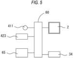
- FIG. 5 is a schematic diagram of the control system in the cup attachment device 1.
- the monitor 2 a nonvolatile memory 65 (hereinafter, a memory 65), and the like are electrically connected to the control unit 60.
- the motor 34 of the cup attachment mechanism 30, a motor (not shown) of the X-direction movement mechanism 35, a motor (not shown) of the Y-direction movement mechanism 36, a motor (not shown) of the Z-direction movement mechanism 37, and the like are electrically connected to the control unit 60.
- the light source 411 of the eyeglasses lens measurement mechanism 40, the imaging element 423, a motor (not shown) for rotating the retroreflective member 415, and the like are electrically connected to the control unit 60.
- control unit 60 includes a CPU (processor), a RAM, a ROM, and the like.
- the CPU may control the driving of each part in the cup attachment device 1.
- the RAM may temporarily store various pieces of information.
- the ROM may store various programs executed by the CPU.
- the operator of the cup attachment device 1 places the eyeglasses lens LE on the support pin 14 of the eyeglasses lens support mechanism 10.
- the eyeglasses lens is held by the support pin 14 abutting against the rear surface of the eyeglasses lens LE.
- the eyeglasses lens LE is a progressive lens LEp will be exemplified.
- FIGs. 6A and 6B are examples of the progressive lens LEp.
- FIG. 6A shows the layout of the progressive lens LEp.
- FIG. 6B shows the printed mark 90 of the progressive lens LEp.
- the progressive lens LEp has a hidden mark M for specifying the type, addition power, refractive index, progressive zone length, and the like of the progressive lens LEp.
- the hidden mark M is formed at a position symmetrical to the geometric center position O (for example, a position 17 mm away from the geometric center position O to the left and right).
- the hidden mark M is formed by a laser or the like, and is represented by a number of symbols and numerical values that vary depending on the type of lens and the manufacturer of the lens.
- the progressive lens LEp includes a distance eyepoint 70, a distance vision power measurement area 75, a near eyepoint 80, a near vision power measurement area 85, and the like.
- the distance eyepoint 70 is a position that matches the pupils of the eyeglass wearer.
- the distance eyepoint 70 is positioned a predetermined distance upward from the geometric center position O (for example, 2 mm upward from the geometric center position O).
- the distance vision power measurement area 75 is an area for measuring the distance vision power.
- the center of the distance vision power measurement area 75 is positioned a predetermined distance upward from the distance eyepoint 70 (for example, 4 mm upward from the distance eyepoint 70).
- the near eyepoint 80 is positioned a predetermined distance downward from the geometric center position O.
- the near vision power measurement area 85 is an area for measuring near vision power.
- the center of the near vision power measurement area 85 is positioned a predetermined distance downward from the near eyepoint 80. Therefore, the geometric center position O, the position of each eyepoint, the position of each measurement area, and the like can be specified based on the hidden mark M of the progressive lens LEp.
- the position of the hidden mark M, the position of each eyepoint, the position of each measurement area, and the like are printed as printed marks 90 on the surface of the progressive lens LEp.
- a horizontal line 91 indicating the position of the hidden mark M, a cross mark 92 indicating the position of each eyepoint, a circular mark 93 indicating the position of each measurement area, and the like are printed as the printed mark 90. Therefore, the geometric center position O, the position of each eyepoint, the position of each measurement area, and the like can also be specified based on the printed mark 90 of the progressive lens LEp.
- the hidden marks M there are many hidden marks M for the progressive lens LEp, and the hidden marks M are added each time a new lens is added. Therefore, automatic detection of the hidden mark M by image processing or the like may be difficult due to the problem of time required for updating template data and matching processing.
- the printed mark 90 of the progressive lens LEp exists as a roughly common mark, and thus automatic detection can be more easily performed than the hidden mark M.
- the printed mark 90 is relatively large in size and easy to recognize, whereas the hidden mark M is small in size, and therefore can be automatically detected more easily than the hidden mark M.
- the operator operates the monitor 2 to set the shaft driving mode for attaching the cup Cu to the progressive lens LEp.
- the control unit 60 turns on the light source 411 of the eyeglasses lens measurement mechanism 40 based on the operation signal input from the monitor 2, and images the progressive lens LEp with the imaging element 423.
- an image (captured image 110) of the progressive lens LEp is acquired.
- an enlarged image 120 based on the image (captured image 110) of the progressive lens LEp is acquired.
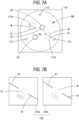
- FIG. 7A is an example of the captured image 110 of the progressive lens LEp
- FIG. 7B is examples of the enlarged image 120 of the progressive lens LEp.
- FIG. 7A shows the captured image 110.
- FIG. 7B shows the enlarged image 120.
- the captured image 110 of the progressive lens LEp is an image that includes the entire lens.
- the captured image 110 may include the hidden mark M, the printed mark 90, and the like.
- the captured image 110 may include an image 112 of the support pin 14, a pattern image (not shown) formed by the index plate 414, and the like.
- the enlarged image 120 of the progressive lens LEp is an image obtained by partially enlarging the captured image 110.
- the control unit 60 detects a specific part from the captured image 110. For example, the control unit 60 detects the printed mark 90 as the specific part by image processing of the captured image 110. As an example, the control unit 60 calculates the luminance of each pixel of the captured image 110, and detects the printed mark 90 based on the change in luminance (such as a rise in luminance). Thereby, for example, the control unit 60 can acquire the positions of the horizontal line 91, cross mark 92, circular mark 93, and the like on the captured image 110. Further, for example, the control unit 60 can acquire the rotation angle of the progressive lens LEp on the placement surface from the inclination angle of the horizontal line 91 on the captured image 110.
- the control unit 60 sets a specific area 115 that includes at least a part of the printed mark 90 in the captured image 110. For example, since the horizontal line 91 has a break in the center, a predetermined pixel range based on this break may be set as the specific area 115. As an example, a pixel range corresponding to an actual distance of 1.5 cm in height x 1.5 cm in width, based on a break in the horizontal line 91, may be set as the specific area 115. Note that two horizontal lines 91 corresponding to the two hidden marks M are printed on the progressive lens LEp. Therefore, for example, the control unit 60 may set the first specific area 115a for one horizontal line 91 and the second specific area 115b for the other horizontal line.
- control unit 60 acquires the enlarged image 120 obtained by enlarging the specific area 115 of the captured image 110.
- the control unit 60 acquires the enlarged image 120 by trimming the specific area 115 from the captured image 110 and stretching the specific area 115 to a predetermined magnification.
- the enlarged image 120 may include the hidden mark M, the horizontal line 91, and the like.
- a first enlarged image 120a of the first specific area 115a and a second enlarged image 120b of the second specific area 115b can be acquired, respectively.
- the control unit 60 Upon acquiring the captured image 110 and the enlarged image 120 (first enlarged image 120a and second enlarged image 120b) of the progressive lens LEp, the control unit 60 displays the shaft driving screen 100 for attaching the cup Cu to the progressive lens LEp on the monitor 2.
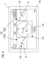
- FIG. 8 is an example of the shaft driving screen 100.
- FIG. 8 shows a state where there is no misalignment between the position of the hidden mark M and the position of the printed mark 90.
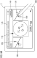
- the shaft driving screen 100 includes the captured image 110 of the progressive lens LEp, the first enlarged image 120a, the second enlarged image 120b, a shaft driving button 130, a manual specification button 140, and the like.
- the shaft driving screen 100 is laid out such that one of the first enlarged image 120a and the second enlarged image 120b is arranged on the left side of the captured image 110, and the other of the first enlarged image 120a and the second enlarged image 120b is arranged on the right side of the captured image 110.
- the control unit 60 may divide the captured image 110 into a left area 110L and a right area 110R by equally dividing the captured image 110 into two in the vertical direction.
- the control unit 60 may control the display such that the enlarged image (first enlarged image 120a in FIG. 8 ) corresponding to the specific area 115 in the left area 110L of the captured image 110 is arranged on the left side of the captured image 110.
- control unit 60 may control the display such that the enlarged image (second enlarged image 120b in FIG. 8 ) corresponding to the specific area 115 positioned in the right area 110R of the captured image 110 is arranged on the right side of the captured image 110.
- a cross mark 125 may be superimposed on at least the enlarged image 120 to make it easier to understand the position of the horizontal line 91.
- the cross mark 125 may also serve as a scale line to make it easier to understand the positional misalignment of the hidden mark M with respect to the position of the horizontal line 91 (details will be described later).
- the control unit 60 displays the cross mark 125 on the enlarged image 120 in a superimposed manner such that the center of the break in the horizontal line 91 and the center of the cross mark 125 match (approximately match) each other.
- the operator confirms whether or not there is a misalignment between the position of the hidden mark M of the progressive lens LEp and the position of the horizontal line 91 by using the enlarged image 120. For example, the operator confirms whether or not the position of the cross mark 125 matches (substantially matches) the position of the hidden mark M shown in the first enlarged image 120a. Further, for example, the operator confirms whether or not the position of the cross mark 125 matches (substantially matches) the position of the hidden mark M shown in the second enlarged image 120b.
- the cross mark 125 may be configured to be able to be switched between display and non-display.
- the operator attaches the cup Cu to the progressive lens LEp.
- the operator mounts the cup Cu to the mounting unit 31 of the cup attachment mechanism 30 and operates the shaft driving button 130.
- the control unit 60 attaches the cup Cu to an appropriate shaft alignment position (for example, the position of the distance eyepoint 70) of the progressive lens LEp based on the operation signal from the shaft driving button 130.
- control unit 60 controls the X-direction movement mechanism 35 and the Z-direction movement mechanism 37 based on the detection result of the printed mark 90, and arranges the attachment center axis S 1 of the arm 32 to the position of the cross mark 92 indicating the position of the distance eyepoint 70. Further, for example, the control unit 60 controls a rotation transmission mechanism (not shown) of the arm 32 based on the detection result of the printed mark 90, and rotates the attachment center axis S1 of the arm 32 in accordance with the rotation angle of the progressive lens LEp. Further, for example, the control unit 60 controls the Y-direction movement mechanism 36 to lower the arm 32 to thus attach the cup Cu to the front surface of the progressive lens LEp.
- each position that can be specified from the hidden mark M of the progressive lens LEp (for example, at least one of the actual geometric center position O, the position of each eyepoint, the position of each measurement area, and the like) and the print position of the printed mark 90 on the progressive lens LEp.
- the printed mark 90 is not necessarily accurate.
- the cup while using the printed mark 90 of the progressive lens LEp, the cup is attached to the appropriate shaft alignment position (position of the distance eyepoint 70) of the progressive lens LEp, and thus the following control may be performed based on the amount of misalignment between the position of the hidden mark M and the position of the printed mark 90.
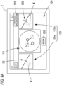
- FIGs. 9A and 9B are examples of the shaft driving screen 100.
- FIG. 9A shows a state where there is no misalignment between the position of the hidden mark M and the position of the printed mark 90.
- FIG. 9B shows a state where the position of the hidden mark M has been specified. For example, when the operator determines that there is a misalignment between the position of the hidden mark M and the position of the horizontal line 91 (cross mark 125) in the first enlarged image 120a and the second enlarged image 120b of the shaft driving screen 100, the operator may manually specify at least the position of the hidden mark M.
- the operator operates the manual specification button 140 on the shaft driving screen 100.
- the control unit 60 may display a guide message 145 or the like to guide the next operation of the operator based on the operation signal from the manual specification button 140.
- a guide message 145 for allowing the operator to specify the position of the hidden mark M may be displayed.
- the operator specifies any position on the enlarged image 120 according to the guide message 145.
- control unit 60 superimposes a specified mark 150 on any position specified on the enlarged image 120, and acquires any position as the position of the hidden mark M.
- control unit 60 acquires any position on the first enlarged image 120a as the position of one of the two hidden marks M, and acquires any position on the second enlarged image 120b as the position of the other of the two hidden marks M.
- control unit 60 calculates the luminance of each pixel of the captured image 110 or the enlarged image 120, and detects the hidden mark M based on a change in luminance (rise in luminance, and the like), and accordingly, the position of the hidden mark M may also be acquired.
- the control unit 60 acquires the position of the printed mark 90.
- the control unit 60 performs image processing on the captured image 110 or the enlarged image 120 of the progressive lens LEp, and detects the printed mark 90, and accordingly, the positions of the center of the break in the horizontal line 91 (cross mark 125), the cross mark 92, the circular mark 93, and the like are acquired.
- the guide message 145 for prompting the operator to specify the printed mark 90 may be displayed, and any position specified by the operator on the enlarged image 120 may be acquired as the positions of the center of the break in the horizontal line 91 (cross mark 125), the cross mark 92, the circular mark 93, and the like.
- the control unit 60 sets the shaft alignment position of the cup Cu with respect to the progressive lens LEp based on these positions. For example, the control unit 60 utilizes the amount of misalignment between the position of the hidden mark M and the position the center of the break in the horizontal line 91, and changes the shaft alignment position determined based on the detection result of the printed mark 90 (that is, the position of the cross mark 92 indicating the position of the distance eyepoint 70), to set the shaft alignment position 160 of the cup Cu.
- FIGs. 10A and 10B are diagrams illustrating the shaft alignment position of the cup Cu.
- FIG. 10A shows the hidden mark M of the progressive lens LEp and the vicinity of the horizontal line 91.
- FIG. 10B shows the periphery of the distance eyepoint 70 of the progressive lens LEp.
- the control unit 60 calculates the amount of misalignment ⁇ x in the left-right direction (X direction) and the amount of misalignment ⁇ z in the front-rear direction (Z direction) of the position of the automatically detected center of the break of the horizontal line 91 (cross mark 125) with respect to the position of the hidden mark M (specified mark 150) specified by the operator.
- the control unit 60 may express the amount of misalignment ⁇ x and the amount of misalignment ⁇ z by the number of pixels of the captured image 110.
- control unit 60 detects the position separated by the amount of misalignment ⁇ x and the amount of misalignment ⁇ z in the left-right direction (X direction) and the front-rear direction (Z direction) with respect to the position of the automatically detected cross mark 92 as the actual position of the distance eyepoint 70. Further, for example, the control unit 60 resets the actual position of the distance eyepoint 70 as the shaft alignment position 160 of the progressive lens LEp.
- the control unit 60 may detect a misalignment between two axis degrees (that is, rotation angle). More specifically, for example, with respect to the line segment connecting the hidden marks M, the rotation angle by which the line segment connecting the centers of the breaks between the left and right horizontal lines 91 rotates may be detected with respect to the geometric center position O.
- the control unit 60 attaches the cup Cu to the shaft alignment position 160 of the progressive lens LEp based on the operation signal from the shaft driving button 130 by the operation of the operator.
- the control unit 60 controls the X-direction movement mechanism 35, the Y-direction movement mechanism 36, the Z-direction movement mechanism 37, and the like, converts the number of pixels of the amount of misalignment ⁇ x and the amount of misalignment ⁇ z into actual distance, and moves the arm 32.
- the control unit 60 rotates the attachment center axis S1 of the arm 32, taking into consideration the rotation angle of the progressive lens LEp and the rotation angle based on the geometric center position O of the horizontal line 91.
- the actual position of the distance eyepoint 70 that can be identified from the hidden mark M of the progressive lens LEp is different from the position of the distance eyepoint 70 that can be identified from the printed mark 90 of the progressive lens LEp.
- the cup Cu can be attached to an appropriate shaft alignment position.
- the shaft alignment device in the present example takes a captured image of the lens surface of the eyeglasses lens, acquires the enlarged image obtained by enlarging a specific area of the captured image of the eyeglasses lens, and causes the display means to display the captured image and the enlarged image on the same screen of the display means.
- the display means For example, when only the captured image of the eyeglasses lens is displayed on the screen, it is possible to understand the positional relationship or the like of a specific area within a wide range of the eyeglasses lens from a bird's-eye view, but it is not possible to confirm the small information contained in the eyeglasses lens (for example, printed marks, hidden marks, and the like).
- the operator can proceed with the operation while simultaneously comparing a wide-range captured image of the eyeglasses lens and a locally enlarged image of the eyeglasses lens, and thus it becomes difficult to lose sight of the various information contained in the eyeglasses lens, and the positional relationship or the like of these pieces of information can be easily understood. Further, for example, since it is difficult to lose sight of various information contained in an eyeglasses lens, it is possible to smoothly adjust the positional relationship or the like of these pieces of information.
- the shaft alignment device in the present example acquires an enlarged image obtained by enlarging the specific area of the captured image of the eyeglasses lens by setting a specific area in the captured image of the eyeglasses lens. For example, by this manner, the operator can easily set a desired specific part of the eyeglasses lens as a specific area, and as a result, it is possible to easily acquire a locally enlarged image that includes the specific part of the eyeglasses lens desired by the operator.
- the shaft alignment device in the present example acquires an enlarged image obtained by enlarging the specific area of the captured image of the eyeglasses lens by setting a preset area in the imaging area of the captured image of the eyeglasses lens as a specific area of the captured image. For example, by this manner, a locally enlarged image of the eyeglasses lens can be easily acquired without the operator specifying a desired specific part of the eyeglasses lens or detecting a specific part of the eyeglasses lens.
- the shaft alignment device in the present example detects a specific part based on the captured image of the eyeglasses lens, sets a specific area including the specific part, and further displays an enlarged image obtained by enlarging such a specific area. For example, by this manner, it is possible to easily recognize a specific part and a specific area of an eyeglasses lens.
- the shaft alignment device detects left and right printed marks of the eyeglasses lens as the specific part from the captured image, and sets the specific area including at least one of one first printed mark and the other second printed mark of the eyeglasses lens. For example, by this manner, information regarding the printed mark put on the eyeglasses lens (for example, the shape or position of the printed mark) can be easily determined from the enlarged image.
- the shaft alignment device sets a first specific area including at least one of the first printed mark or the first hidden mark, and a second specific area including at least one of the second printed mark or the second hidden mark, arranges one of a first enlarged image of the first specific area and a second enlarged image of the second specific area on the left side of the captured image, and arranges the other on the right side of the captured image.
- a first specific area including at least one of the first printed mark or the first hidden mark and a second specific area including at least one of the second printed mark or the second hidden mark, arranges one of a first enlarged image of the first specific area and a second enlarged image of the second specific area on the left side of the captured image, and arranges the other on the right side of the captured image.
- the shaft alignment device arranges the first enlarged image or the second enlarged image corresponding to the specific part detected in the left area of the captured image of the eyeglasses lens on the left side of the captured image, and arranges the first enlarged image or the second enlarged image corresponding to the specific part detected in the right area of the captured image on the right side of the captured image. For example, by this manner, since the direction of the specific part on the eyeglasses lens matches the direction of the arrangement of the enlarged image, it becomes easier to visually determine a specific part, and it becomes easier to perform subsequent operations.
- the captured image of the eyeglasses lens is the entire image of the eyeglasses lens, and includes at least one of both the first printed mark and the second printed mark and both the first hidden mark and the second hidden mark.
- the axis degree of the two printed marks can be confirmed. Therefore, for example, rotational misalignment of a printed mark (hidden mark) with respect to the lens surface of an eyeglasses lens can be easily understood.
- the shaft alignment device in the present example acquires the positions of the left and right printed marks put on the eyeglasses lens, acquires the positions of the left and right hidden marks put on the eyeglasses lens, and sets the shaft alignment position of the holding means that pinches the eyeglasses lens based on the printed mark position and the hidden mark position to hold the eyeglasses lens. For example, by using both the printed mark position and the hidden mark position of the eyeglasses lens, the shaft alignment position of the eyeglasses lens can be appropriately set.
- the shaft alignment position of the eyeglasses lens can be easily determined by using the printed mark position of the eyeglasses lens, and further, the accuracy of the shaft alignment position of the eyeglasses lens can be improved by using the hidden mark position of the eyeglasses lens.
- the shaft alignment device in the present example changes the shaft alignment position of the holding means with respect to the eyeglasses lens based on the amount of misalignment between the printed mark position and the hidden mark position on the eyeglasses lens. For example, by this manner, it is possible to accurately correct the shaft alignment position based on the printed mark position on the eyeglasses lens, and it is possible to set the shaft alignment position at an appropriate position on the eyeglasses lens.
- the shaft alignment device in the present example takes a captured image of the lens surface of an eyeglasses lens, detects left and right printed marks of the eyeglasses lens based on the captured image, and acquires the printed mark position based on the detection results.
- printed marks put on an eyeglasses lens exist as roughly common marks and can be detected more easily than hidden marks, and as a result, the printed mark position can be easily acquired.
- the shaft alignment device in the present example displays identification information based on the printed mark position detected from the captured image of the eyeglasses lens on the captured image in a superimposed manner. For example, by this manner, the operator can easily understand the printed mark position and intuitively perform various operations on the printed mark position. Furthermore, for example, when the hidden mark position and the printed mark position are misaligned, it becomes easier to determine the direction and degree of the misalignment.
- the shaft alignment device in the present example inputs an operation signal for the operator to specify the hidden mark position on the eyeglasses lens, and thereby acquires the specified position on the captured image of the eyeglasses lens as a hidden mark position.
- the hidden marks put on the eyeglasses lens may be more difficult to detect than the printed marks because the hidden marks are represented by different symbols and numbers depending on the type of eyeglasses lens and the manufacturer of the eyeglasses lens.
- the hidden mark position can be easily acquired.
- the printed mark 90 is detected as a specific part from the captured image 110 taken by the progressive lens LEp, but the present invention is not limited thereto.
- the hidden mark M may be detected as a specific part from the captured image 110 of the progressive lens LEp.
- the control unit 60 may set the specific area 115 including the hidden mark M in the captured image 110 and acquire the enlarged image 120 obtained by enlarging the specific area 115 including the hidden mark M.
- control unit 60 may display the captured image 110 of the progressive lens LEp and the enlarged image of the hidden mark M on the shaft driving screen 100.
- the control unit 60 may layout the shaft driving screen 100 such that an enlarged image including one hidden mark M is arranged on the left side of the captured image 110, and an enlarged image containing the other hidden mark M is arranged on the right side of the captured image 110.
- the control unit 60 may control the display such that the captured image 110 is divided into the left area 110L and the right area 110R, and an enlarged image of the hidden mark M in the left area 110L of the captured image 110 is arranged on the left side of the captured image 110.
- the display may be controlled such that an enlarged image of the hidden mark M positioned in the right area 110R of the captured image 110 is arranged on the right side of the captured image 110.
- the shaft alignment device may detect left and right hidden marks of the eyeglasses lens as the specific part from the captured image, and set the specific area including at least one of one first hidden mark and the other second hidden mark of the eyeglasses lens. For example, by this manner, information regarding the hidden mark put on the eyeglasses lens (for example, the shape or position of the hidden mark) can be easily determined from the enlarged image.
- the control unit 60 may detect whether or not there is a misalignment between the position of the hidden mark M of the progressive lens LEp and the position of the printed mark 90, and output the detection result as an alert.
- the control unit 60 may output the presence or absence of a misalignment between the position of the hidden mark M and the position of the printed mark 90, or the extent of the misalignment, as an alert.
- such an alert may be expressed as at least any of the following: displaying a message, highlighting the shaft driving screen, generating an audio guide, flashing or lighting a lamp, and the like.
Landscapes
- Engineering & Computer Science (AREA)
- Mechanical Engineering (AREA)
- Chemical & Material Sciences (AREA)
- Ceramic Engineering (AREA)
- Inorganic Chemistry (AREA)
- Eyeglasses (AREA)
Abstract
A shaft alignment device is used in a process of processing a peripheral edge of an eyeglasses lens. The shaft alignment device includes an imaging means that takes a captured image of a lens surface of the eyeglasses lens, an enlarged image acquisition means that acquires an enlarged image obtained by enlarging a specific area of the captured image, and a display control means that causes a display means to display the captured image taken by the imaging means and the enlarged image acquired by the enlarged image acquisition means on a same screen of the display means. According to the shaft alignment device, it is possible to set a shaft alignment position of the eyeglasses lens.
Description
- The present disclosure relates to a shaft alignment device used in a process of processing a peripheral edge of an eyeglasses lens, and a shaft alignment program used in the shaft alignment device.
- As an example of a shaft alignment device used in the process of processing the peripheral edge of an eyeglasses lens, a cup attachment device that attaches a processing jig (cup) to an eyeglasses lens is known (see
JP2020-038268A - Incidentally, with the conventional shaft alignment device, it is sometimes difficult to understand the hidden mark position or the printed mark position from the captured image of the progressive lens. Furthermore, there is a possibility that there is a misalignment between the hidden mark position and the printed mark position, and it is difficult to recognize this misalignment.
- A technical object of the present invention is to provide a shaft alignment device and a shaft alignment program that enable to appropriately set a shaft alignment position of an eyeglasses lens.
- (1) A shaft alignment device used in a process of processing a peripheral edge of an eyeglasses lens, the shaft alignment device including:
- an imaging means that takes a captured image of a lens surface of the eyeglasses lens;
- an enlarged image acquisition means that acquires an enlarged image obtained by enlarging a specific area of the captured image; and
- a display control means that causes a display means to display the captured image taken by the imaging means and the enlarged image acquired by the enlarged image acquisition means on a same screen of the display means.
- (2) The shaft alignment device according to the above-described (1), further including:
- an area setting means that sets the specific area of the captured image,
- in which the enlarged image acquisition means acquires the enlarged image obtained by enlarging the specific area set by the area setting means.
- (3) The shaft alignment device according to the above-described (1), further including:
- an area setting means that sets the specific area of the captured image,
- in which the area setting means sets a preset area in an imaging area of the captured image taken by the imaging means as the specific area.
- (4) The shaft alignment device according to the above-described (2), further including:
- a detection means that detects a specific part based on the captured image taken by the imaging means,
- in which the area setting means sets the specific area including the specific part detected by the detection means, and
- the display control means enlarges the specific area set by the area setting means and causes the display means to display the enlarged specific area as the enlarged image.
- (5) The shaft alignment device according to the above-described (4),
- in which the detection means detects left and right printed marks of the eyeglasses lens as the specific part from the captured image, and
- the area setting means sets the specific area including at least one of the left and right printed marks which are a first printed mark and a second printed mark of the eyeglasses lens.
- (6) The shaft alignment device according to the above-described (4) or (5),
- in which the detection means detects left and right hidden marks of the eyeglasses lens as the specific part from the captured image, and
- the area setting means sets the specific area including at least one of the left and right hidden marks which are a first hidden mark and a second hidden mark of the eyeglasses lens.
- (7) The shaft alignment device according to the above-described (6),
- in which the area setting means sets a first specific area including at least one of the first printed mark or the first hidden mark, and a second specific area including at least one of the second printed mark or the second hidden mark, and
- the display control means arranges one of a first enlarged image of the first specific area and a second enlarged image of the second specific area on a left side of the captured image, and arranges the other on a right side of the captured image.
- (8) The shaft alignment device according to the above-described (6 )or (7),
in which the captured image of the eyeglasses lens is an entire image of the eyeglasses lens, and includes at least one of both the first printed mark and the second printed mark and both the first hidden mark and the second hidden mark. - (9) The shaft alignment device according to any one of the above-described (1) to (8), further including:
- a printed mark position acquisition means that acquires printed mark positions of left and right printed marks put on the eyeglasses lens;
- a hidden mark position acquisition means that acquires hidden mark positions of left and right hidden marks put on the eyeglasses lens; and
- a shaft alignment position setting means that sets a shaft alignment position of a holding means that pinches the eyeglasses lens based on the printed mark position acquired by the printed mark position acquisition means and the hidden mark position acquired by the hidden mark position acquisition means to hold the eyeglasses lens.
- (10) The shaft alignment device according to the above-described (9),
in which the shaft alignment position setting means sets the shaft alignment position by changing the shaft alignment position of the holding means with respect to the eyeglasses lens based on an amount of misalignment between the printed mark position and the hidden mark position. - (11) The shaft alignment device according to the above-described (9) or (10), further including:
- a printed mark detection means that detects the left and right printed marks of the eyeglasses lens based on the captured image,
- in which the printed mark position acquisition means acquires the printed mark position based on a detection result of the printed mark detection means.
- (12) The shaft alignment device according to the above-described (11),
in which the display control means displays identification information based on the printed mark position on the captured image in a superimposed manner, based on a detection result of the printed mark detection means. - (13) The shaft alignment device according to any one of the above-described (9) to (12), further including:
- an operation means that inputs an operation signal for an operator to specify the hidden mark position,
- in which the hidden mark position acquisition means acquires a position specified on the captured image by the operation means as the hidden mark position.
- (14) A shaft alignment program of a shaft alignment device used in a process of processing a peripheral edge of an eyeglasses lens, the shaft alignment program including instructions which, when executed by a controller of the shaft alignment device, cause the shaft alignment device to perform:
- an imaging step of taking a captured image of a lens surface of the eyeglasses lens;
- an enlarged image acquisition step of acquiring an enlarged image obtained by enlarging a specific area of the captured image; and
- a display control step of causing a display means to display the captured image taken in the imaging step and the enlarged image acquired in the enlarged image acquisition step on a same screen of the display means.
- (15) The shaft alignment program according to the above-described (14), further including instructions which causes the shaft alignment device to perform:
- a printed mark position acquisition step of acquiring printed mark positions of left and right printed marks put on the eyeglasses lens;
- a hidden mark position acquisition step of acquiring hidden mark positions of left and right hidden marks put on the eyeglasses lens; and
- a shaft alignment position setting step of setting a shaft alignment position of a holding means that pinches the eyeglasses lens based on the printed mark position acquired in the printed mark position acquisition step and the hidden mark position acquired in the hidden mark position acquisition step to hold the eyeglasses lens.
- Exemplary embodiment(s) of the present invention will be described in detail based on the following figures, wherein:
-
FIG. 1 is an external view of a cup attachment device; -
FIG. 2 is a schematic diagram of an eyeglasses lens support mechanism; -
FIG. 3 is a schematic diagram of a cup attachment mechanism; -
FIG. 4 is a schematic diagram of an eyeglasses lens measurement mechanism; -
FIG. 5 is a schematic diagram of a control system; -
FIGs. 6A and 6B are examples of a progressive lens; -
FIG. 7A is an example of a captured image of the progressive lens, andFIG. 7B is examples of an enlarged image of the progressive lens; -
FIG. 8 is an example of a shaft driving screen; -
FIGs. 9A and9B are examples of the shaft driving scree; and -
FIGs. 10A and 10B are diagrams illustrating the shaft alignment position of the cup. - An outline of a shaft alignment device according to an embodiment of the present disclosure will be described. The items classified by <> below can be used independently or in association with each other.
- The shaft alignment device of the present embodiment may be a shaft alignment device used in the process of processing the peripheral edge of an eyeglasses lens. For example, the shaft alignment device may be a shaft alignment device including a shaft alignment position setting means that sets a shaft alignment position of a holding means that pinches the eyeglasses lens to hold the eyeglasses lens. For example, the holding means may be a holding means (for example, a chuck shaft) included in an eyeglasses lens peripheral edge processing device. Further, for example, the shaft alignment device may be a cup attachment device including a cup attachment means that attaches a cup, which is a processing jig for holding the eyeglasses lens in the holding means.
- The shaft alignment device of the present embodiment may include a cup attachment means (for example, a cup attachment mechanism 30). For example, the cup attachment means may attach a cup, which is a processing jig for holding the eyeglasses lens to the holding means, to the eyeglasses lens based on the shaft alignment position set by the shaft alignment position setting means (details will be described later). For example, the cup attachment means may attach the cup to at least one of the front surface and rear surface of the eyeglasses lens.
- The shaft alignment device of the present embodiment may include an imaging means (for example, an eyeglasses lens measurement mechanism 40). For example, the imaging means may capture a captured image of a lens surface of the eyeglasses lens. For example, the imaging means may have an imaging range capable of imaging a wide range of the lens surface of the eyeglasses lens. As an example, the imaging means may have an imaging range capable of taking the entire lens surface of the eyeglasses lens.
- For example, a captured image of an eyeglasses lens is the entire image of the eyeglasses lens, and may include at least one of both the left and right printed marks (first printed mark and second printed mark) put on the eyeglasses lens and both the left and right hidden marks (first hidden mark and second hidden mark) put on the eyeglasses lens. For example, in this case, the axis degree of the left and right printed marks or the left and right hidden marks with respect to the center position (for example, geometric center position) of the eyeglasses lens can be easily understood.
- For example, the imaging means may include an imaging optical system (for example, an imaging optical system 420) as a part of the imaging means. For example, the imaging optical system may image the eyeglasses lens by receiving reflected light flux of natural light from the eyeglasses lens. Further, for example, the imaging optical system may image the eyeglasses lens by receiving a reflected light flux from the eyeglasses lens by the illumination optical system (for example, an illumination optical system 410). For example, the imaging means may have at least an imaging element.
- The shaft alignment device of the present embodiment may include a detection means (for example, a control unit 60). For example, the detection means may detect a specific part based on a captured image taken by the imaging means. For example, the detection means may detect the specific part by analyzing the captured image based on the captured image of the eyeglasses lens. For example, various image processing methods may be applied to the captured image analysis processing. As an example, the specific part may be detected by detecting a change in at least one of the luminance value, saturation, hue, and the like of the captured image. Further, as an example, the specific part may be detected by using a template image of the specific part prepared in advance and calculating the degree of similarity between the template image and the captured image.
- For example, the detection means may detect the left and right printed marks of the eyeglasses lens as specific parts from the captured image. For example, in this case, the detection means may also serve as a printed mark detection means, which will be described later. For example, the detection means may detect the left and right hidden marks of the eyeglasses lens as specific parts from the captured image. For example, in this case, the detection means may also serve as a hidden mark detection means, which will be described later. It is needless to say that, for example, the detection means may detect both the left and right printed marks and the left and right hidden marks of the eyeglasses lens as specific parts from the captured image.
- The shaft alignment device of the present embodiment may include an area setting means (for example, the control unit 60). For example, the area setting means may set a specific area of the captured image taken by the imaging means. For example, by this manner, the operator can easily set a desired specific part of the eyeglasses lens as a specific area, and as a result, it is possible to easily acquire a locally enlarged image that includes the specific part of the eyeglasses lens desired by the operator.
- For example, the area setting means may set any position input by the operation of the operator of the operation means as the specific area. For example, in this case, the shaft alignment device may include an operation means (for example, a monitor 2) through which an operator inputs an operation signal for specifying a specific area, and the area setting means may set the position specified on the captured image by the operation means as the specific area.
- For example, the area setting means may set a specific area including the specific part detected by the detection means. For example, the area setting means may set a predetermined area based on the specific area as the specific area.
- For example, the area setting means may set a specific area including at least one of one first printed mark and the other second printed mark of the eyeglasses lens as the specific area including the specific part detected by the detection means (the printed mark detection means). For example, in this case, the area setting means may set one specific area that includes both the first printed mark and the second printed mark, or may set two specific areas for each of the first printed mark and the second printed mark.
- For example, the area setting means may set a specific area including at least one of one first hidden mark and the other second hidden mark of the eyeglasses lens as the specific area including the specific part detected by the detection means (the hidden mark detection means). For example, in this case, the area setting means may set one specific area that includes both the first hidden mark and the second hidden mark, or may set two specific areas for each of the first hidden mark and the second hidden mark.
- Note that, for example, the area setting means may respectively set a first specific area including at least one of the first printed mark or the first hidden mark, and a second specific area including at least one of the second printed mark or the second hidden mark.
- For example, the area setting means may set a predetermined area in an imaging area of the captured image taken by the imaging means as the specific area. For example, the area set in advance in the imaging area of the captured image may be an area set in advance by associating the area with a predetermined coordinate position with respect to the captured image. For example, by this manner, a locally enlarged image of the eyeglasses lens can be easily acquired without the operator specifying a desired specific part of the eyeglasses lens or detecting a specific part of the eyeglasses lens. As an example, the area setting means may set, as the specific area, a position where at least one of preset left and right printed marks or left and right hidden marks is arranged in the imaging area of the captured image.
- Note that the shaft alignment device may include an alignment means for positioning the eyeglasses lens with respect to the imaging means (imaging optical system). For example, the alignment means may be a centripetal mechanism that centripetally centers the eyeglasses lens in order to make the center position of the eyeglasses lens match the optical axis position of the imaging optical system. As an example, in this case, the area setting means may set, as the specific area, the positions where the left and right printed marks or hidden marks are arranged in the imaging area of the imaging optical system when the eyeglasses lens is centripetally centered by the centripetal mechanism. Further, for example, the alignment means may be a guide mechanism for causing the operator to arrange the predetermined position of the eyeglasses lens to a predetermined position (predetermined area) with respect to the imaging optical system. As an example, in this case, the operator may move the eyeglasses lens to display a guide on the captured image for placing the left and right printed marks or hidden marks within a predetermined area with respect to the imaging area of the imaging optical system. For example, the area setting means may set a position corresponding to such a guide as the specific area.
- The shaft alignment device of the present embodiment may include an enlarged image acquisition means (for example, the control unit 60). For example, the enlarged image acquisition means may acquire an enlarged image obtained by enlarging a specific area of a captured image of an eyeglasses lens. For example, the specific area of the captured image of the eyeglasses lens may be a partial area included in the captured image. For example, the area may include at least one of a printed mark and a hidden mark put on an eyeglasses lens.
- For example, the enlarged image acquisition means may acquire an enlarged image taken by the imaging means that takes an enlarged image of an eyeglasses lens. For example, such imaging means may share at least a part of the configuration with the above-described <Imaging means>. As an example, in this case, a captured image and an enlarged image may be acquired by switching the imaging magnification of the imaging means. Further, for example, such imaging means may be provided separately from the above-described <Imaging means>. That is, for example, the imaging means that takes a wide-range captured image of the eyeglasses lens and the imaging means that takes an enlarged image of the eyeglasses lens in a narrow range may be provided, respectively.
- For example, the enlarged image acquisition means may acquire an enlarged image by processing the captured image taken by the above-described <Imaging means>. For example, in this case, the enlarged image acquisition means may acquire an enlarged image obtained by enlarging the specific area set in the captured image by the area setting means. For example, an enlarged image may be acquired by interpolating pixels of the captured image such that a specific area set in the captured image is enlarged to a predetermined magnification.
- The shaft alignment device of the present embodiment may include a display control means (for example, the control unit 60). For example, the display control means may cause a display means to display the captured image of the eyeglasses lens taken by the imaging means.
- For example, the display control means may cause the display means to display the captured image of the eyeglasses lens taken by the imaging means and the enlarged image obtained by enlarging a specific area of the captured image acquired by the enlarged image acquisition means on the same screen of the display means. For example, the display control means may cause the display means to display the captured image of the eyeglasses lens and one or more enlarged images of the eyeglasses lens on the same screen of the display means. For example, when only the captured image of the eyeglasses lens is displayed on the screen, it is possible to understand the positional relationship or the like of a specific area within a wide range of the eyeglasses lens from a bird's-eye view, but it is not possible to confirm the small information contained in the eyeglasses lens (for example, printed marks, hidden marks, and the like). Furthermore, for example, when only an enlarged image of the eyeglasses lens is displayed on the screen, small pieces of information contained in the eyeglasses lens can be easily confirmed, but the positional relationship or the like of small pieces of information on the eyeglasses lens cannot be seen. However, for example, the operator can proceed with the operation while simultaneously comparing a wide-range captured image of the eyeglasses lens and a locally enlarged image of the eyeglasses lens, and thus it becomes difficult to lose sight of the various information contained in the eyeglasses lens, and the positional relationship or the like of these pieces of information can be easily understood. Further, for example, since it is difficult to lose sight of various information contained in an eyeglasses lens, it is possible to smoothly adjust the positional relationship or the like of these pieces of information. For example, the relative positional relationship between the left and right printed marks and the left and right hidden marks can be understood from the captured image of the eyeglasses lens, and the shape or positional relationship of individual printed marks and hidden marks can be understood from the enlarged image of the eyeglasses lens, and accordingly, it is possible to easily position the eyeglasses lens.
- For example, the display control means may enlarge the specific area set by the area setting means and cause the display means to display the enlarged specific area it as an enlarged image. For example, the display control means may cause the display means to display an enlarged image obtained by enlarging a specific area including at least one of one first printed mark and the other second printed mark of the eyeglasses lens. In addition, for example, the display control means may cause the display means to display an enlarged image obtained by enlarging a specific area including at least one of one first hidden mark and the other second printed mark of the eyeglasses lens. It is needless to say that, for example, the display control means may cause the display means to respectively display a first enlarged image obtained by enlarging the first specific area including at least one of the first printed mark or the first hidden mark, and a second enlarged image obtained by enlarging the second specific area including at least one of the second printed mark or the second hidden mark.
- For example, the display control means may cause the display means to display the captured image of the eyeglasses lens, the first enlarged image of the first specific area, and the second enlarged image of the second specific area on the same screen of the display means. For example, the display control means may arrange one of the first enlarged image and the second enlarged image on the left side of the captured image, and may arrange the other on the right side of the captured image. For example, by this manner, each of two printed marks and a hidden mark put on an eyeglasses lens can be easily recognized using two enlarged images.
- Note that, for example, the display control means may arrange the first enlarged image or the second enlarged image corresponding to the specific part detected in the left area of the captured image of the eyeglasses lens on the left side of the captured image, and arrange the first enlarged image or the second enlarged image corresponding to the specific part detected in the right area of the captured image on the right side of the captured image. For example, by this manner, since the direction of the specific part on the eyeglasses lens matches the direction of the arrangement of the enlarged image, it becomes easier to visually determine a specific part, and it becomes easier to perform subsequent operations.
- The shaft alignment device of the present embodiment may include an imaging means (for example, an eyeglasses lens measurement mechanism 40). For example, the imaging means may capture a captured image of a lens surface of the eyeglasses lens. Note that, for example, the imaging means in <Setting of shaft alignment position> may also be used as the imaging means in <Display of captured image and enlarged image of eyeglasses lens>.
- The shaft alignment device of the present embodiment may include a printed mark detection means (for example, the control unit 60). For example, the printed mark detection means may detect the left and right printed marks of the eyeglasses lens based on the captured image. For example, the printed mark detection means may detect one first printed mark and the other second printed mark of the eyeglasses lens, respectively, based on the captured image.
- The shaft alignment device of the present embodiment may include a printed mark position acquisition means (for example, the control unit 60). For example, the printed mark position acquisition means may acquire the printed mark positions of the left and right printed marks put on an eyeglasses lens.
- Note that, for example, an eyeglasses lens is provided with respective left and right hidden marks based on the geometric center position of the eyeglasses lens, and printed marks are provided to correspond to the hidden marks. Therefore, for example, the printed mark position acquisition means may acquire the printed mark positions of two printed marks corresponding to the left and right hidden marks as the printed mark positions of the left and right printed marks.
- For example, the printed mark position acquisition means may acquire any position input by the operation of the operator of the operation means as the printed mark position. For example, in this case, the shaft alignment device may include an operation means (for example, the monitor 2) through which an operator inputs an operation signal for specifying a printed mark position, and the printed mark position acquisition means may acquire the position specified on the captured image by the operation means as the printed mark position. Note that the printed mark position acquisition means may acquire, as the printed mark position, a position specified on an enlarged image obtained by enlarging a specific area of the captured image by the operation means.
- For example, the printed mark position acquisition means may automatically acquire the printed mark positions based on the detection results of the printed mark detection means. Note that, for example, in eyeglasses lens, printed marks exist as roughly common marks, the printed marks do not have the combination of symbols and numbers that hidden marks do, and thus the printed marks can be easily detected.
- The shaft alignment device of the present embodiment may include a hidden mark detection means (for example, the control unit 60). For example, the hidden mark detection means may detect the left and right hidden marks of the eyeglasses lens based on the captured image. For example, the hidden mark detection means may detect one first hidden mark and the other second hidden mark of the eyeglasses lens, respectively, based on the captured image.
- The shaft alignment device of the present embodiment may include a hidden mark position acquisition means (for example, the control unit 60). For example, the hidden mark position acquisition means may acquire the hidden mark positions of left and right hidden marks put on an eyeglasses lens.
- For example, the hidden mark position acquisition means may acquire any position input by the operation of the operator of the operation means as the hidden mark position. For example, in this case, the shaft alignment device may include an operation means (for example, the monitor 2) through which an operator inputs an operation signal for specifying a hidden mark position, and the hidden mark position acquisition means may acquire the position specified on the captured image by the operation means as the hidden mark position. Note that, for example, the hidden mark position acquisition means may acquire, as the hidden mark position, a position specified on an enlarged image obtained by enlarging a specific area of the captured image by the operation means. For example, the hidden marks put on the eyeglasses lens may be more difficult to detect than the printed marks because the hidden marks are represented by different symbols and numbers depending on the type of eyeglasses lens and the manufacturer of the eyeglasses lens. However, by directly specifying the hidden mark position on the captured image of the eyeglasses lens, the hidden mark position can be easily acquired.
- In addition, for example, the hidden mark position acquisition means may automatically acquire the hidden mark positions based on the detection results of the hidden mark detection means.
- The shaft alignment device of the present embodiment may include a display control means (for example, the control unit 60). For example, the display control means may cause the display means to display the captured image of the eyeglasses lens taken by the imaging means. Note that, for example, the display control means in <Setting of shaft alignment position> may also be used as the display control means in <Display of captured image and enlarged image of eyeglasses lens>.
- For example, the display control means may cause to the display means to display identification information based on the printed mark position on the captured image in a superimposed manner, based on the detection result of the printed mark detection means. Note that, for example, the display control means may cause the display means to display the identification information on an enlarged image obtained by enlarging a specific area of the captured image in a superimposed manner. For example, the identification information may be any information that allows the operator to identify the printed mark position. For example, the identification information may be at least one of a detection line superimposed on the shape of the printed mark, a predetermined mark indicating the printed mark position (for example, at least one of a symbol, a scale, a mark, an icon, and the like). It is needless to say that, for example, the identification information may be information different from these. For example, by this manner, the operator can easily understand the printed mark position and intuitively perform various operations on the printed mark position. Furthermore, for example, when the printed mark position and the hidden mark position are misaligned, it becomes easier to determine the direction and degree of the misalignment.
- The shaft alignment device of the present embodiment may include a shaft alignment position setting means (for example, the control unit 60). For example, the shaft alignment position setting means may set the shaft alignment position of a holding means that pinches the eyeglasses lens to hold the eyeglasses lens. For example, the shaft alignment position setting means may set, as the shaft alignment position, a position where the eyeglasses lens is held by the holding means of the eyeglasses lens peripheral edge processing device (that is, a position where the holding means is attached to the eyeglasses lens). For example, the shaft alignment position may be at least one of the optical center position, geometric center position, and the like of the eyeglasses lens.
- For example, the shaft alignment position setting means may set the shaft alignment position of a holding means that pinches the eyeglasses lens, based on the captured image of the eyeglasses lens, to hold the eyeglasses lens. In addition, for example, the shaft alignment position setting means may set the shaft alignment position of a holding means that pinches the eyeglasses lens, based on the enlarged image obtained by enlarging the specific area of the captured image of the eyeglasses lens, to hold the eyeglasses lens.
- For example, the shaft alignment position setting means may set the shaft alignment position of the holding means that pinches the eyeglasses lens based on the printed mark position acquired by the printed mark position acquisition means and the hidden mark position acquired by the hidden mark position acquisition means to hold the eyeglasses lens. For example, by this manner, the shaft alignment position of the eyeglasses lens can be easily determined by using the printed mark position of the eyeglasses lens, and further, the accuracy of the shaft alignment position of the eyeglasses lens can be improved by using the hidden mark position of the eyeglasses lens.
- For example, the shaft alignment position setting means may set the shaft alignment position by changing the shaft alignment position of the holding means with respect to the eyeglasses lens based on the amount of misalignment between the printed mark position and the hidden mark position. For example, the shaft alignment position setting means may set the shaft alignment position based on the printed mark position, and further move the shaft alignment position based on the amount of misalignment between the printed mark position and the hidden mark position to reset the shaft alignment position. For example, the shaft alignment position setting means may set the shaft alignment position based on the hidden mark position, and further move the shaft alignment position based on the amount of misalignment between the printed mark position and the hidden mark position to reset the shaft alignment position.
- Note that, for example, an allowable range may be provided for the amount of misalignment between the printed mark position and the hidden mark position. For example, such an allowable range may be any value set by the operator. Further, for example, such an allowable range may be a fixed value that is preset based on the results of experiments or simulations.
- The present disclosure is not limited to the device described in the present embodiment. For example, terminal control software (program) that performs the functions of the above-described embodiment is supplied to the device or the system via a network or various storage media, and the control device (for example, CPU or the like) of the device or the system can also read and execute the program.
- Hereinafter, one example of the present embodiment will be described below with reference to the drawings. In the present example, a cup attachment device is taken as an example of the shaft alignment device.
-
FIG. 1 is an external view of acup attachment device 1. For example, thecup attachment device 1 includes amonitor 2, an eyeglasseslens support mechanism 10, acup attachment mechanism 30, an eyeglasses lens measurement mechanism 40 (refer toFIG. 4 ), and the like. - In the present example, a touch panel function is added to the
monitor 2, and themonitor 2 functions as an operation unit (controller). Note that themonitor 2 and the operation unit may be provided separately, and in this case, at least one of a mouse, a joystick, a keyboard, a mobile terminal, and the like may be used as the operation unit. Further, in the present example, themonitor 2 uses a liquid crystal display (LCD). It is needless to say that themonitor 2 may be an organic electro Luminescence (EL) display, a plasma display, or the like. - For example, the
monitor 2 displays various types of information including at least one of information on a cup attached to an eyeglasses lens, information on optical characteristics of an eyeglasses lens (first information), information different from optical characteristic information of an eyeglasses lens (second information), and the like. Note that, as an example, the information on a cup attached to the eyeglasses lens may be the external shape of the cup and the like. Further, as an example, the first information of the eyeglasses lens may be at least one of spherical power, cylindrical power, astigmatic axis angle, prism amount, and the like. Further, as an example, the second information of the eyeglasses lens may be at least one of the outer shape, bead shape, printed mark, hidden mark, mark, hole shape, hole position, and the like of the eyeglasses lens. - In addition, for example, the
monitor 2 displays various operation screens including at least one of the following: a shaft driving screen for attaching a cup to an eyeglasses lens, a layout screen for inputting a machining layout for the eyeglasses lens, a machining condition setting screen for inputting machining conditions for the eyeglasses lens, and the like. -
FIG. 2 is a schematic diagram of the eyeglasseslens support mechanism 10. The eyeglasseslens support mechanism 10 supports an eyeglasses lens LE. For example, the eyeglasseslens support mechanism 10 includes acylindrical base 11, aring member 12, aprotective cover 13, asupport pin 14, and the like. - For example, inside the
cylindrical base 11, an index plate 44, a retroreflective member 45 and the like, which will be described later, are housed. For example, thering member 12 is fixed to the top of thecylindrical base 11. For example, theprotective cover 13 is fixed to the top of thering member 12. For example, thesupport pin 14 is fixed to the top of theprotective cover 13. For example, the support pins 14 are composed of three pieces, and eachsupport pin 14 is arranged at the same distance and at the same angle with respect to an optical axis L1 of the eyeglasses lens measurement mechanism 40 (refer toFIG. 4 ). -
FIG. 3 is a schematic diagram of thecup attachment mechanism 30. The cup attachment mechanism 50 attaches a cup to an eyeglasses lens. For example, thecup attachment mechanism 30 includes a mountingunit 31, anarm 32, anarm holding base 33, amotor 34, anX-direction movement mechanism 35, a Y-direction movement mechanism 36, a Z-direction movement mechanism 37, and the like. - For example, a cup Cu is mounted to the mounting
unit 31. For example, the mountingunit 31 has anuneven unit 31a that fits into an uneven unit Cua formed on the cup Cu. For example, the mountingunit 31 is fixed to thearm 32. For example, thearm 32 includes a rotation transmission mechanism (not shown) for variably holding the rotation angle of the mountingunit 31 in the horizontal direction. For example, thearm 32 is fixed to thearm holding base 33. For example, thearm holding base 33 includes themotor 34. For example, the rotation of themotor 34 is transmitted to the mountingunit 31 via a rotation transmission mechanism (not shown) of thearm 32. As a result, for example, the mountingunit 31 rotates around an attachment center axis S1 of the cup Cu. - For example, the
X-direction movement mechanism 35, the Y-direction movement mechanism 36, and the Z-direction movement mechanism 37 each include a motor (not shown) or the like. For example, theX-direction movement mechanism 35 moves in the left-right direction (X-direction) of thecup attachment device 1. For example, above theX-direction movement mechanism 35, the Y-direction movement mechanism 36 is installed. For example, the Y-direction movement mechanism 36 moves in the up-down direction (Y-direction) of thecup attachment device 1. For example, above the Y-direction movement mechanism 36, the Z-direction movement mechanism 37 is installed. For example, the Z-direction movement mechanism 37 moves in the front-rear direction (Z-direction) of thecup attachment device 1. For example, the Z-direction movement mechanism 37 holds thearm 32, thearm holding base 33, and themotor 34 included in thearm holding base 33. - For example, in the present example, by moving the
X-direction movement mechanism 35, the Y-direction movement mechanism 36, the Z-direction movement mechanism 37, thearm 32, and the like move in the left-right direction with respect to thecup attachment device 1. Further, for example, in the present example, by moving the Z-direction movement mechanism 37, thearm 32 and the like move in the front-rear direction with respect to thecup attachment device 1. As a result, the mountingunit 31 moves to the top of the eyeglasseslens support mechanism 10, for example. - Furthermore, for example, in the present example, by moving the Y-
direction movement mechanism 36, the Z-direction movement mechanism 37, thearm 32, and the like move in the up-down direction with respect to thecup attachment device 1. As a result, for example, the cup Cu mounted to the mountingunit 31 is shaft-driven to the eyeglasses lens. -
FIG. 4 is a schematic diagram of the eyeglasseslens measurement mechanism 40. The eyeglasseslens measurement mechanism 40 measures optical characteristic information (first information) of an eyeglasses lens. Moreover, the eyeglasseslens measurement mechanism 40 detects second information different from the optical characteristic information of the eyeglasses lens. For example, the eyeglasseslens measurement mechanism 40 includes the illuminationoptical system 410, the imagingoptical system 420, and the like. - The illumination
optical system 410 projects an illumination light flux from the front side of the eyeglasses lens LE. For example, the illuminationoptical system 410 includes alight source 411, ahalf mirror 412, aconcave mirror 413, anindex plate 414, aretroreflective member 415, and the like. For example, thelight source 411 irradiates the eyeglasses lens LE with a light flux. For example, theconcave mirror 413 reflects the light flux from the light source and shapes the light flux from the light source into a parallel light flux (substantially parallel light flux) having a larger diameter than the eyeglasses lens LE. For example, theindex plate 414 has a predetermined pattern formed of the multiple openings (light flux passage holes). For example, theretroreflective member 415 reflects the light flux from the light source in the same (substantially the same) direction as the direction of incidence. For example, theretroreflective member 415 may be rotated at high speed around the optical axis L1 by a motor (not shown) or the like in order to uniformly reflect the light flux from the light source. - The imaging
optical system 420 images the eyeglasses lens LE from the front side. For example, the imagingoptical system 420 includes aconcave mirror 413, anaperture 421, animaging lens 422, animaging element 423, and the like. For example, theaperture 421 is arranged at the focal position (approximately the focal position) of theconcave mirror 413. For example, theaperture 421 has a conjugate (substantially conjugate) positional relationship with thelight source 411. For example, theimaging element 423 images the reflected light flux emitted from thelight source 411 and reflected by theretroreflective member 415. For example, the focal position of the imaging element 323 is aligned with the vicinity of the front surface of the eyeglasses lens LE. As a result, it is possible to image at least one of the printed mark, the hidden mark, mark, and the like on the eyeglasses lens LE in a roughly focused state. -
FIG. 5 is a schematic diagram of the control system in thecup attachment device 1. For example, themonitor 2, a nonvolatile memory 65 (hereinafter, a memory 65), and the like are electrically connected to thecontrol unit 60. For example, themotor 34 of thecup attachment mechanism 30, a motor (not shown) of theX-direction movement mechanism 35, a motor (not shown) of the Y-direction movement mechanism 36, a motor (not shown) of the Z-direction movement mechanism 37, and the like are electrically connected to thecontrol unit 60. Further, for example, thelight source 411 of the eyeglasseslens measurement mechanism 40, theimaging element 423, a motor (not shown) for rotating theretroreflective member 415, and the like are electrically connected to thecontrol unit 60. - For example, the
control unit 60 includes a CPU (processor), a RAM, a ROM, and the like. For example, the CPU may control the driving of each part in thecup attachment device 1. For example, the RAM may temporarily store various pieces of information. For example, the ROM may store various programs executed by the CPU. - The control operation of the
cup attachment device 1 having the above configuration will be described. For example, the operator of thecup attachment device 1 places the eyeglasses lens LE on thesupport pin 14 of the eyeglasseslens support mechanism 10. For example, the eyeglasses lens is held by thesupport pin 14 abutting against the rear surface of the eyeglasses lens LE. In the present example, a case where the eyeglasses lens LE is a progressive lens LEp will be exemplified. -
FIGs. 6A and 6B are examples of the progressive lens LEp.FIG. 6A shows the layout of the progressive lens LEp.FIG. 6B shows the printedmark 90 of the progressive lens LEp. For example, the progressive lens LEp has a hidden mark M for specifying the type, addition power, refractive index, progressive zone length, and the like of the progressive lens LEp. For example, the hidden mark M is formed at a position symmetrical to the geometric center position O (for example, a position 17 mm away from the geometric center position O to the left and right). For example, the hidden mark M is formed by a laser or the like, and is represented by a number of symbols and numerical values that vary depending on the type of lens and the manufacturer of the lens. - Further, for example, the progressive lens LEp includes a
distance eyepoint 70, a distance visionpower measurement area 75, anear eyepoint 80, a near visionpower measurement area 85, and the like. For example, thedistance eyepoint 70 is a position that matches the pupils of the eyeglass wearer. For example, thedistance eyepoint 70 is positioned a predetermined distance upward from the geometric center position O (for example, 2 mm upward from the geometric center position O). For example, the distance visionpower measurement area 75 is an area for measuring the distance vision power. For example, the center of the distance visionpower measurement area 75 is positioned a predetermined distance upward from the distance eyepoint 70 (for example, 4 mm upward from the distance eyepoint 70). For example, thenear eyepoint 80 is positioned a predetermined distance downward from the geometric center position O. For example, the near visionpower measurement area 85 is an area for measuring near vision power. For example, the center of the near visionpower measurement area 85 is positioned a predetermined distance downward from thenear eyepoint 80. Therefore, the geometric center position O, the position of each eyepoint, the position of each measurement area, and the like can be specified based on the hidden mark M of the progressive lens LEp. - For example, the position of the hidden mark M, the position of each eyepoint, the position of each measurement area, and the like are printed as printed
marks 90 on the surface of the progressive lens LEp. For example, ahorizontal line 91 indicating the position of the hidden mark M, across mark 92 indicating the position of each eyepoint, acircular mark 93 indicating the position of each measurement area, and the like are printed as the printedmark 90. Therefore, the geometric center position O, the position of each eyepoint, the position of each measurement area, and the like can also be specified based on the printedmark 90 of the progressive lens LEp. - As mentioned above, there are many hidden marks M for the progressive lens LEp, and the hidden marks M are added each time a new lens is added. Therefore, automatic detection of the hidden mark M by image processing or the like may be difficult due to the problem of time required for updating template data and matching processing. On the other hand, the printed
mark 90 of the progressive lens LEp exists as a roughly common mark, and thus automatic detection can be more easily performed than the hidden mark M. Moreover, the printedmark 90 is relatively large in size and easy to recognize, whereas the hidden mark M is small in size, and therefore can be automatically detected more easily than the hidden mark M. - The operator operates the
monitor 2 to set the shaft driving mode for attaching the cup Cu to the progressive lens LEp. For example, thecontrol unit 60 turns on thelight source 411 of the eyeglasseslens measurement mechanism 40 based on the operation signal input from themonitor 2, and images the progressive lens LEp with theimaging element 423. As a result, an image (captured image 110) of the progressive lens LEp is acquired. Furthermore, anenlarged image 120 based on the image (captured image 110) of the progressive lens LEp is acquired. -
FIG. 7A is an example of the capturedimage 110 of the progressive lens LEp, andFIG. 7B is examples of theenlarged image 120 of the progressive lens LEp.FIG. 7A shows the capturedimage 110.FIG. 7B shows theenlarged image 120. For example, the capturedimage 110 of the progressive lens LEp is an image that includes the entire lens. For example, the capturedimage 110 may include the hidden mark M, the printedmark 90, and the like. Further, for example, the capturedimage 110 may include animage 112 of thesupport pin 14, a pattern image (not shown) formed by theindex plate 414, and the like. For example, theenlarged image 120 of the progressive lens LEp is an image obtained by partially enlarging the capturedimage 110. - The
control unit 60 detects a specific part from the capturedimage 110. For example, thecontrol unit 60 detects the printedmark 90 as the specific part by image processing of the capturedimage 110. As an example, thecontrol unit 60 calculates the luminance of each pixel of the capturedimage 110, and detects the printedmark 90 based on the change in luminance (such as a rise in luminance). Thereby, for example, thecontrol unit 60 can acquire the positions of thehorizontal line 91,cross mark 92,circular mark 93, and the like on the capturedimage 110. Further, for example, thecontrol unit 60 can acquire the rotation angle of the progressive lens LEp on the placement surface from the inclination angle of thehorizontal line 91 on the capturedimage 110. - Subsequently, the
control unit 60 sets a specific area 115 that includes at least a part of the printedmark 90 in the capturedimage 110. For example, since thehorizontal line 91 has a break in the center, a predetermined pixel range based on this break may be set as the specific area 115. As an example, a pixel range corresponding to an actual distance of 1.5 cm in height x 1.5 cm in width, based on a break in thehorizontal line 91, may be set as the specific area 115. Note that twohorizontal lines 91 corresponding to the two hidden marks M are printed on the progressive lens LEp. Therefore, for example, thecontrol unit 60 may set the firstspecific area 115a for onehorizontal line 91 and the secondspecific area 115b for the other horizontal line. - Further, the
control unit 60 acquires theenlarged image 120 obtained by enlarging the specific area 115 of the capturedimage 110. For example, thecontrol unit 60 acquires theenlarged image 120 by trimming the specific area 115 from the capturedimage 110 and stretching the specific area 115 to a predetermined magnification. For example, theenlarged image 120 may include the hidden mark M, thehorizontal line 91, and the like. Here, a firstenlarged image 120a of the firstspecific area 115a and a secondenlarged image 120b of the secondspecific area 115b can be acquired, respectively. - Upon acquiring the captured
image 110 and the enlarged image 120 (firstenlarged image 120a and secondenlarged image 120b) of the progressive lens LEp, thecontrol unit 60 displays theshaft driving screen 100 for attaching the cup Cu to the progressive lens LEp on themonitor 2. -
FIG. 8 is an example of theshaft driving screen 100.FIG. 8 shows a state where there is no misalignment between the position of the hidden mark M and the position of the printedmark 90. For example, theshaft driving screen 100 includes the capturedimage 110 of the progressive lens LEp, the firstenlarged image 120a, the secondenlarged image 120b, ashaft driving button 130, amanual specification button 140, and the like. - For example, the
shaft driving screen 100 is laid out such that one of the firstenlarged image 120a and the secondenlarged image 120b is arranged on the left side of the capturedimage 110, and the other of the firstenlarged image 120a and the secondenlarged image 120b is arranged on the right side of the capturedimage 110. For example, thecontrol unit 60 may divide the capturedimage 110 into aleft area 110L and aright area 110R by equally dividing the capturedimage 110 into two in the vertical direction. For example, thecontrol unit 60 may control the display such that the enlarged image (firstenlarged image 120a inFIG. 8 ) corresponding to the specific area 115 in theleft area 110L of the capturedimage 110 is arranged on the left side of the capturedimage 110. Similarly, for example, thecontrol unit 60 may control the display such that the enlarged image (secondenlarged image 120b inFIG. 8 ) corresponding to the specific area 115 positioned in theright area 110R of the capturedimage 110 is arranged on the right side of the capturedimage 110. - For example, in the
shaft driving screen 100, across mark 125 may be superimposed on at least theenlarged image 120 to make it easier to understand the position of thehorizontal line 91. For example, thecross mark 125 may also serve as a scale line to make it easier to understand the positional misalignment of the hidden mark M with respect to the position of the horizontal line 91 (details will be described later). For example, thecontrol unit 60 displays thecross mark 125 on theenlarged image 120 in a superimposed manner such that the center of the break in thehorizontal line 91 and the center of thecross mark 125 match (approximately match) each other. - When the
shaft driving screen 100 is displayed on themonitor 2, the operator confirms whether or not there is a misalignment between the position of the hidden mark M of the progressive lens LEp and the position of thehorizontal line 91 by using theenlarged image 120. For example, the operator confirms whether or not the position of thecross mark 125 matches (substantially matches) the position of the hidden mark M shown in the firstenlarged image 120a. Further, for example, the operator confirms whether or not the position of thecross mark 125 matches (substantially matches) the position of the hidden mark M shown in the secondenlarged image 120b. - Note that, for example, when there is no misalignment between the position of the hidden mark M and the position of the horizontal line 91 (cross mark 125) in the
enlarged image 120, thecross mark 125 is superimposed on the hidden mark M, and thus the hidden mark M may be difficult to see. Therefore, for example, thecross mark 125 may be configured to be able to be switched between display and non-display. - When the operator determines that there is no misalignment between the position of the hidden mark M and the position of the horizontal line 91 (cross mark 125) in the first
enlarged image 120a and the secondenlarged image 120b, the operator attaches the cup Cu to the progressive lens LEp. For example, the operator mounts the cup Cu to the mountingunit 31 of thecup attachment mechanism 30 and operates theshaft driving button 130. For example, thecontrol unit 60 attaches the cup Cu to an appropriate shaft alignment position (for example, the position of the distance eyepoint 70) of the progressive lens LEp based on the operation signal from theshaft driving button 130. - For example, the
control unit 60 controls theX-direction movement mechanism 35 and the Z-direction movement mechanism 37 based on the detection result of the printedmark 90, and arranges the attachmentcenter axis S 1 of thearm 32 to the position of thecross mark 92 indicating the position of thedistance eyepoint 70. Further, for example, thecontrol unit 60 controls a rotation transmission mechanism (not shown) of thearm 32 based on the detection result of the printedmark 90, and rotates the attachment center axis S1 of thearm 32 in accordance with the rotation angle of the progressive lens LEp. Further, for example, thecontrol unit 60 controls the Y-direction movement mechanism 36 to lower thearm 32 to thus attach the cup Cu to the front surface of the progressive lens LEp. - In addition, there may be a misalignment between each position that can be specified from the hidden mark M of the progressive lens LEp (for example, at least one of the actual geometric center position O, the position of each eyepoint, the position of each measurement area, and the like) and the print position of the printed
mark 90 on the progressive lens LEp. In other words, there may be a misalignment between the position of the hidden mark M on the progressive lens LEp and the print position of the printedmark 90 on the progressive lens LEp. Therefore, the printedmark 90 is not necessarily accurate. - Therefore, in the present example, while using the printed
mark 90 of the progressive lens LEp, the cup is attached to the appropriate shaft alignment position (position of the distance eyepoint 70) of the progressive lens LEp, and thus the following control may be performed based on the amount of misalignment between the position of the hidden mark M and the position of the printedmark 90. -
FIGs. 9A and9B are examples of theshaft driving screen 100.FIG. 9A shows a state where there is no misalignment between the position of the hidden mark M and the position of the printedmark 90.FIG. 9B shows a state where the position of the hidden mark M has been specified. For example, when the operator determines that there is a misalignment between the position of the hidden mark M and the position of the horizontal line 91 (cross mark 125) in the firstenlarged image 120a and the secondenlarged image 120b of theshaft driving screen 100, the operator may manually specify at least the position of the hidden mark M. - For example, the operator operates the
manual specification button 140 on theshaft driving screen 100. For example, thecontrol unit 60 may display aguide message 145 or the like to guide the next operation of the operator based on the operation signal from themanual specification button 140. For example, aguide message 145 for allowing the operator to specify the position of the hidden mark M may be displayed. For example, the operator specifies any position on theenlarged image 120 according to theguide message 145. - For example, the
control unit 60 superimposes a specifiedmark 150 on any position specified on theenlarged image 120, and acquires any position as the position of the hidden mark M. For example, thecontrol unit 60 acquires any position on the firstenlarged image 120a as the position of one of the two hidden marks M, and acquires any position on the secondenlarged image 120b as the position of the other of the two hidden marks M. - As described above, automatic detection of the hidden mark M on the progressive lens LEp may be difficult, but by image-processing the captured
image 110 or theenlarged image 120 and detecting the hidden mark M, it is also possible to acquire the position of the hidden mark M. As an example, thecontrol unit 60 calculates the luminance of each pixel of the capturedimage 110 or theenlarged image 120, and detects the hidden mark M based on a change in luminance (rise in luminance, and the like), and accordingly, the position of the hidden mark M may also be acquired. - Further, for example, the
control unit 60 acquires the position of the printedmark 90. For example, thecontrol unit 60 performs image processing on the capturedimage 110 or theenlarged image 120 of the progressive lens LEp, and detects the printedmark 90, and accordingly, the positions of the center of the break in the horizontal line 91 (cross mark 125), thecross mark 92, thecircular mark 93, and the like are acquired. It is needless to say that, for example, theguide message 145 for prompting the operator to specify the printedmark 90 may be displayed, and any position specified by the operator on theenlarged image 120 may be acquired as the positions of the center of the break in the horizontal line 91 (cross mark 125), thecross mark 92, thecircular mark 93, and the like. - For example, upon acquiring the position of the hidden mark M and the position of the center of the break in the horizontal line 91 (cross mark 125) respectively, the
control unit 60 sets the shaft alignment position of the cup Cu with respect to the progressive lens LEp based on these positions. For example, thecontrol unit 60 utilizes the amount of misalignment between the position of the hidden mark M and the position the center of the break in thehorizontal line 91, and changes the shaft alignment position determined based on the detection result of the printed mark 90 (that is, the position of thecross mark 92 indicating the position of the distance eyepoint 70), to set the shaft alignment position 160 of the cup Cu. -
FIGs. 10A and 10B are diagrams illustrating the shaft alignment position of the cup Cu.FIG. 10A shows the hidden mark M of the progressive lens LEp and the vicinity of thehorizontal line 91.FIG. 10B shows the periphery of thedistance eyepoint 70 of the progressive lens LEp. For example, thecontrol unit 60 calculates the amount of misalignment δx in the left-right direction (X direction) and the amount of misalignment δz in the front-rear direction (Z direction) of the position of the automatically detected center of the break of the horizontal line 91 (cross mark 125) with respect to the position of the hidden mark M (specified mark 150) specified by the operator. For example, thecontrol unit 60 may express the amount of misalignment δx and the amount of misalignment δz by the number of pixels of the capturedimage 110. - Next, for example, the
control unit 60 detects the position separated by the amount of misalignment δx and the amount of misalignment δz in the left-right direction (X direction) and the front-rear direction (Z direction) with respect to the position of the automatically detectedcross mark 92 as the actual position of thedistance eyepoint 70. Further, for example, thecontrol unit 60 resets the actual position of thedistance eyepoint 70 as the shaft alignment position 160 of the progressive lens LEp. - In addition, for example, when there is a misalignment in the axis degree between the line segment connecting the left and right hidden marks M and the line segment connecting the center of the break of the left and right horizontal lines 91 (the left and right cross marks 125), the
control unit 60 may detect a misalignment between two axis degrees (that is, rotation angle). More specifically, for example, with respect to the line segment connecting the hidden marks M, the rotation angle by which the line segment connecting the centers of the breaks between the left and righthorizontal lines 91 rotates may be detected with respect to the geometric center position O. - For example, the
control unit 60 attaches the cup Cu to the shaft alignment position 160 of the progressive lens LEp based on the operation signal from theshaft driving button 130 by the operation of the operator. For example, thecontrol unit 60 controls theX-direction movement mechanism 35, the Y-direction movement mechanism 36, the Z-direction movement mechanism 37, and the like, converts the number of pixels of the amount of misalignment δx and the amount of misalignment δz into actual distance, and moves thearm 32. Further, for example, thecontrol unit 60 rotates the attachment center axis S1 of thearm 32, taking into consideration the rotation angle of the progressive lens LEp and the rotation angle based on the geometric center position O of thehorizontal line 91. For example, by this manner, the actual position of thedistance eyepoint 70 that can be identified from the hidden mark M of the progressive lens LEp is different from the position of thedistance eyepoint 70 that can be identified from the printedmark 90 of the progressive lens LEp. However, by using the printedmark 90, which is easy to automatically detect, the cup Cu can be attached to an appropriate shaft alignment position. - As described above, for example, the shaft alignment device in the present example takes a captured image of the lens surface of the eyeglasses lens, acquires the enlarged image obtained by enlarging a specific area of the captured image of the eyeglasses lens, and causes the display means to display the captured image and the enlarged image on the same screen of the display means. For example, when only the captured image of the eyeglasses lens is displayed on the screen, it is possible to understand the positional relationship or the like of a specific area within a wide range of the eyeglasses lens from a bird's-eye view, but it is not possible to confirm the small information contained in the eyeglasses lens (for example, printed marks, hidden marks, and the like). Furthermore, for example, when only an enlarged image of the eyeglasses lens is displayed on the screen, small pieces of information contained in the eyeglasses lens can be easily confirmed, but the positional relationship or the like of small pieces of information on the eyeglasses lens cannot be seen. However, for example, according to the shaft alignment device of the present example, the operator can proceed with the operation while simultaneously comparing a wide-range captured image of the eyeglasses lens and a locally enlarged image of the eyeglasses lens, and thus it becomes difficult to lose sight of the various information contained in the eyeglasses lens, and the positional relationship or the like of these pieces of information can be easily understood. Further, for example, since it is difficult to lose sight of various information contained in an eyeglasses lens, it is possible to smoothly adjust the positional relationship or the like of these pieces of information.
- Further, for example, the shaft alignment device in the present example acquires an enlarged image obtained by enlarging the specific area of the captured image of the eyeglasses lens by setting a specific area in the captured image of the eyeglasses lens. For example, by this manner, the operator can easily set a desired specific part of the eyeglasses lens as a specific area, and as a result, it is possible to easily acquire a locally enlarged image that includes the specific part of the eyeglasses lens desired by the operator.
- Further, for example, the shaft alignment device in the present example acquires an enlarged image obtained by enlarging the specific area of the captured image of the eyeglasses lens by setting a preset area in the imaging area of the captured image of the eyeglasses lens as a specific area of the captured image. For example, by this manner, a locally enlarged image of the eyeglasses lens can be easily acquired without the operator specifying a desired specific part of the eyeglasses lens or detecting a specific part of the eyeglasses lens.
- Further, for example, the shaft alignment device in the present example detects a specific part based on the captured image of the eyeglasses lens, sets a specific area including the specific part, and further displays an enlarged image obtained by enlarging such a specific area. For example, by this manner, it is possible to easily recognize a specific part and a specific area of an eyeglasses lens.
- Further, for example, the shaft alignment device according to the present example detects left and right printed marks of the eyeglasses lens as the specific part from the captured image, and sets the specific area including at least one of one first printed mark and the other second printed mark of the eyeglasses lens. For example, by this manner, information regarding the printed mark put on the eyeglasses lens (for example, the shape or position of the printed mark) can be easily determined from the enlarged image.
- Further, for example, the shaft alignment device according to the present example sets a first specific area including at least one of the first printed mark or the first hidden mark, and a second specific area including at least one of the second printed mark or the second hidden mark, arranges one of a first enlarged image of the first specific area and a second enlarged image of the second specific area on the left side of the captured image, and arranges the other on the right side of the captured image. For example, by this manner, each of two printed marks and a hidden mark put on an eyeglasses lens can be easily recognized using two enlarged images.
- Further, for example, the shaft alignment device according to the present example arranges the first enlarged image or the second enlarged image corresponding to the specific part detected in the left area of the captured image of the eyeglasses lens on the left side of the captured image, and arranges the first enlarged image or the second enlarged image corresponding to the specific part detected in the right area of the captured image on the right side of the captured image. For example, by this manner, since the direction of the specific part on the eyeglasses lens matches the direction of the arrangement of the enlarged image, it becomes easier to visually determine a specific part, and it becomes easier to perform subsequent operations.
- Further, for example, in the shaft alignment device according to the present example, the captured image of the eyeglasses lens is the entire image of the eyeglasses lens, and includes at least one of both the first printed mark and the second printed mark and both the first hidden mark and the second hidden mark. For example, by including both the first printed mark and the second printed mark (or the first hidden mark and the second hidden mark) in the captured image of the eyeglasses lens, the axis degree of the two printed marks (hidden marks) can be confirmed. Therefore, for example, rotational misalignment of a printed mark (hidden mark) with respect to the lens surface of an eyeglasses lens can be easily understood.
- Further, for example, the shaft alignment device in the present example acquires the positions of the left and right printed marks put on the eyeglasses lens, acquires the positions of the left and right hidden marks put on the eyeglasses lens, and sets the shaft alignment position of the holding means that pinches the eyeglasses lens based on the printed mark position and the hidden mark position to hold the eyeglasses lens. For example, by using both the printed mark position and the hidden mark position of the eyeglasses lens, the shaft alignment position of the eyeglasses lens can be appropriately set. For example, the shaft alignment position of the eyeglasses lens can be easily determined by using the printed mark position of the eyeglasses lens, and further, the accuracy of the shaft alignment position of the eyeglasses lens can be improved by using the hidden mark position of the eyeglasses lens.
- Further, for example, the shaft alignment device in the present example changes the shaft alignment position of the holding means with respect to the eyeglasses lens based on the amount of misalignment between the printed mark position and the hidden mark position on the eyeglasses lens. For example, by this manner, it is possible to accurately correct the shaft alignment position based on the printed mark position on the eyeglasses lens, and it is possible to set the shaft alignment position at an appropriate position on the eyeglasses lens.
- Further, for example, the shaft alignment device in the present example takes a captured image of the lens surface of an eyeglasses lens, detects left and right printed marks of the eyeglasses lens based on the captured image, and acquires the printed mark position based on the detection results. For example, printed marks put on an eyeglasses lens exist as roughly common marks and can be detected more easily than hidden marks, and as a result, the printed mark position can be easily acquired.
- Furthermore, for example, the shaft alignment device in the present example displays identification information based on the printed mark position detected from the captured image of the eyeglasses lens on the captured image in a superimposed manner. For example, by this manner, the operator can easily understand the printed mark position and intuitively perform various operations on the printed mark position. Furthermore, for example, when the hidden mark position and the printed mark position are misaligned, it becomes easier to determine the direction and degree of the misalignment.
- Further, for example, the shaft alignment device in the present example inputs an operation signal for the operator to specify the hidden mark position on the eyeglasses lens, and thereby acquires the specified position on the captured image of the eyeglasses lens as a hidden mark position. For example, the hidden marks put on the eyeglasses lens may be more difficult to detect than the printed marks because the hidden marks are represented by different symbols and numbers depending on the type of eyeglasses lens and the manufacturer of the eyeglasses lens. However, by directly specifying the hidden mark position on the captured image of the eyeglasses lens, the hidden mark position can be easily acquired.
- In the present example, the printed
mark 90 is detected as a specific part from the capturedimage 110 taken by the progressive lens LEp, but the present invention is not limited thereto. For example, the hidden mark M may be detected as a specific part from the capturedimage 110 of the progressive lens LEp. For example, in this case, thecontrol unit 60 may set the specific area 115 including the hidden mark M in the capturedimage 110 and acquire theenlarged image 120 obtained by enlarging the specific area 115 including the hidden mark M. - Furthermore, for example, the
control unit 60 may display the capturedimage 110 of the progressive lens LEp and the enlarged image of the hidden mark M on theshaft driving screen 100. As an example, thecontrol unit 60 may layout theshaft driving screen 100 such that an enlarged image including one hidden mark M is arranged on the left side of the capturedimage 110, and an enlarged image containing the other hidden mark M is arranged on the right side of the capturedimage 110. Note that, for example, thecontrol unit 60 may control the display such that the capturedimage 110 is divided into theleft area 110L and theright area 110R, and an enlarged image of the hidden mark M in theleft area 110L of the capturedimage 110 is arranged on the left side of the capturedimage 110. Similarly, the display may be controlled such that an enlarged image of the hidden mark M positioned in theright area 110R of the capturedimage 110 is arranged on the right side of the capturedimage 110. - The shaft alignment device according to the present example may detect left and right hidden marks of the eyeglasses lens as the specific part from the captured image, and set the specific area including at least one of one first hidden mark and the other second hidden mark of the eyeglasses lens. For example, by this manner, information regarding the hidden mark put on the eyeglasses lens (for example, the shape or position of the hidden mark) can be easily determined from the enlarged image.
- In the present example, an example of a configuration in which the operator confirms whether or not there is a misalignment between the position of the hidden mark M of the progressive lens LEp and the position of the printed
mark 90 has been described, but the present invention is not limited thereto. For example, thecontrol unit 60 may detect whether or not there is a misalignment between the position of the hidden mark M of the progressive lens LEp and the position of the printedmark 90, and output the detection result as an alert. For example, thecontrol unit 60 may output the presence or absence of a misalignment between the position of the hidden mark M and the position of the printedmark 90, or the extent of the misalignment, as an alert. As an example, such an alert may be expressed as at least any of the following: displaying a message, highlighting the shaft driving screen, generating an audio guide, flashing or lighting a lamp, and the like.
Claims (15)
- A shaft alignment device used in a process of processing a peripheral edge of an eyeglasses lens, the shaft alignment device comprising:an imaging means that takes a captured image of a lens surface of the eyeglasses lens;an enlarged image acquisition means that acquires an enlarged image obtained by enlarging a specific area of the captured image; anda display control means that causes a display means to display the captured image taken by the imaging means and the enlarged image acquired by the enlarged image acquisition means on a same screen of the display means.
- The shaft alignment device according to claim 1, further comprising:an area setting means that sets the specific area of the captured image,wherein the enlarged image acquisition means acquires the enlarged image obtained by enlarging the specific area set by the area setting means.
- The shaft alignment device according to claim 1, further comprising:an area setting means that sets the specific area of the captured image,wherein the area setting means sets a preset area in an imaging area of the captured image taken by the imaging means as the specific area.
- The shaft alignment device according to claim 2, further comprising:a detection means that detects a specific part based on the captured image taken by the imaging means,wherein the area setting means sets the specific area including the specific part detected by the detection means, andthe display control means enlarges the specific area set by the area setting means and causes the display means to display the enlarged specific area as the enlarged image.
- The shaft alignment device according to claim 4,wherein the detection means detects left and right printed marks of the eyeglasses lens as the specific part from the captured image, andthe area setting means sets the specific area including at least one of the left and right printed marks which are a first printed mark and a second printed mark of the eyeglasses lens.
- The shaft alignment device according to claim 4 or 5,wherein the detection means detects left and right hidden marks of the eyeglasses lens as the specific part from the captured image, andthe area setting means sets the specific area including at least one of the left and right hidden marks which are a first hidden mark and a second hidden mark of the eyeglasses lens.
- The shaft alignment device according to claim 6,wherein the area setting means sets a first specific area including at least one of the first printed mark or the first hidden mark, and a second specific area including at least one of the second printed mark or the second hidden mark, andthe display control means arranges one of a first enlarged image of the first specific area and a second enlarged image of the second specific area on a left side of the captured image, and arranges the other on a right side of the captured image.
- The shaft alignment device according to claim 6 or 7,
wherein the captured image of the eyeglasses lens is an entire image of the eyeglasses lens, and includes at least one of both the first printed mark and the second printed mark and both the first hidden mark and the second hidden mark. - The shaft alignment device according to any one of claims 1 to 8, further comprising:a printed mark position acquisition means that acquires printed mark positions of left and right printed marks put on the eyeglasses lens;a hidden mark position acquisition means that acquires hidden mark positions of left and right hidden marks put on the eyeglasses lens; anda shaft alignment position setting means that sets a shaft alignment position of a holding means that pinches the eyeglasses lens based on the printed mark position acquired by the printed mark position acquisition means and the hidden mark position acquired by the hidden mark position acquisition means to hold the eyeglasses lens.
- The shaft alignment device according to claim 9,
wherein the shaft alignment position setting means sets the shaft alignment position by changing the shaft alignment position of the holding means with respect to the eyeglasses lens based on an amount of misalignment between the printed mark position and the hidden mark position. - The shaft alignment device according to claim 9 or 10, further comprising:a printed mark detection means that detects the left and right printed marks of the eyeglasses lens based on the captured image,wherein the printed mark position acquisition means acquires the printed mark position based on a detection result of the printed mark detection means.
- The shaft alignment device according to claim 11,
wherein the display control means displays identification information based on the printed mark position on the captured image in a superimposed manner, based on a detection result of the printed mark detection means. - The shaft alignment device according to any one of claims 9 to 12, further comprising:an operation means that inputs an operation signal for an operator to specify the hidden mark position,wherein the hidden mark position acquisition means acquires a position specified on the captured image by the operation means as the hidden mark position.
- A shaft alignment program of a shaft alignment device used in a process of processing a peripheral edge of an eyeglasses lens, the shaft alignment program comprising instructions which, when executed by a controller of the shaft alignment device, cause the shaft alignment device to perform:an imaging step of taking a captured image of a lens surface of the eyeglasses lens;an enlarged image acquisition step of acquiring an enlarged image obtained by enlarging a specific area of the captured image; anda display control step of causing a display means to display the captured image taken in the imaging step and the enlarged image acquired in the enlarged image acquisition step on a same screen of the display means.
- The shaft alignment program according to claim 14, further comprising instructions which causes the shaft alignment device to perform:a printed mark position acquisition step of acquiring printed mark positions of left and right printed marks put on the eyeglasses lens;a hidden mark position acquisition step of acquiring hidden mark positions of left and right hidden marks put on the eyeglasses lens; anda shaft alignment position setting step of setting a shaft alignment position of a holding means that pinches the eyeglasses lens based on the printed mark position acquired in the printed mark position acquisition step and the hidden mark position acquired in the hidden mark position acquisition step to hold the eyeglasses lens.
Applications Claiming Priority (2)
| Application Number | Priority Date | Filing Date | Title |
|---|---|---|---|
| JP2023057514A JP2024145241A (en) | 2023-03-31 | 2023-03-31 | Centering device and centering program |
| JP2023057513A JP2024145240A (en) | 2023-03-31 | 2023-03-31 | Centering device and centering program |
Publications (1)
| Publication Number | Publication Date |
|---|---|
| EP4438228A1 true EP4438228A1 (en) | 2024-10-02 |
Family
ID=90482410
Family Applications (1)
| Application Number | Title | Priority Date | Filing Date |
|---|---|---|---|
| EP24166175.0A Pending EP4438228A1 (en) | 2023-03-31 | 2024-03-26 | Shaft alignment device and shaft alignment program |
Country Status (1)
| Country | Link |
|---|---|
| EP (1) | EP4438228A1 (en) |
Citations (4)
| Publication number | Priority date | Publication date | Assignee | Title |
|---|---|---|---|---|
| JP2006110692A (en) * | 2004-10-18 | 2006-04-27 | Topcon Corp | Lens positioning method and lens suction jig mounting device used in lens suction jig mounting device |
| JP2006247825A (en) * | 2005-02-08 | 2006-09-21 | Topcon Corp | Eyeglass lens suction jig mounting device |
| US7715023B2 (en) * | 2004-03-31 | 2010-05-11 | Kabushiki Kaisha Topcon | Jig mounting apparatus |
| JP2020038268A (en) | 2018-09-03 | 2020-03-12 | 株式会社ニデック | Cup mounting device |
-
2024
- 2024-03-26 EP EP24166175.0A patent/EP4438228A1/en active Pending
Patent Citations (4)
| Publication number | Priority date | Publication date | Assignee | Title |
|---|---|---|---|---|
| US7715023B2 (en) * | 2004-03-31 | 2010-05-11 | Kabushiki Kaisha Topcon | Jig mounting apparatus |
| JP2006110692A (en) * | 2004-10-18 | 2006-04-27 | Topcon Corp | Lens positioning method and lens suction jig mounting device used in lens suction jig mounting device |
| JP2006247825A (en) * | 2005-02-08 | 2006-09-21 | Topcon Corp | Eyeglass lens suction jig mounting device |
| JP2020038268A (en) | 2018-09-03 | 2020-03-12 | 株式会社ニデック | Cup mounting device |
Similar Documents
| Publication | Publication Date | Title |
|---|---|---|
| JP4970149B2 (en) | Cup mounting device | |
| US10379387B2 (en) | Method and device for checking refractive power distribution and centering | |
| JP5467962B2 (en) | Measurement setting data creation device, measurement setting data creation method, program for measurement setting data creation device, and dimension measurement device | |
| EP2636481B1 (en) | Apparatus having cup attaching unit | |
| US6481095B1 (en) | Cup attaching apparatus | |
| JPH11287972A (en) | Centering device | |
| KR101126303B1 (en) | Method for manually centering an ophthalmic lens, method for centering/blocking an ophthalmic lens, and centering/blocking device | |
| JP2012037257A (en) | Measurement setting data creation device, measurement setting data creation method, and program for measurement setting data creation device | |
| JPH11216650A (en) | Centering device | |
| JP4104297B2 (en) | Cup mounting device | |
| JP2024145240A (en) | Centering device and centering program | |
| CN106896532B (en) | Shaft alignment device and shaft alignment position setting program | |
| JP2024145241A (en) | Centering device and centering program | |
| EP3495093B1 (en) | Eyeglasses lens processing system and eyeglasses lens processing method | |
| JP7172029B2 (en) | Alignment device | |
| JP7268308B2 (en) | cup mounting device | |
| JP2015031847A (en) | Glasses parameter calculation device, glasses parameter calculation program | |
| JP6433258B2 (en) | How to make a binocular loupe | |
| JP2018163107A (en) | Lens meter | |
| JP7225644B2 (en) | lens measuring device | |
| JP7329427B2 (en) | lens meter | |
| JP7373378B2 (en) | lens measuring device | |
| JP2024143740A (en) | LAYOUT SETTING DEVICE AND LAYOUT SETTING PROGRAM | |
| JP2026046893A (en) | Step formation data setting device, step formation data setting program, and spectacle lens rim processing device | |
| JP2019045660A (en) | Spectacle mapping information acquisition device, spectacle mapping information acquisition method, and spectacle mapping information acquisition program |
Legal Events
| Date | Code | Title | Description |
|---|---|---|---|
| PUAI | Public reference made under article 153(3) epc to a published international application that has entered the european phase |
Free format text: ORIGINAL CODE: 0009012 |
|
| STAA | Information on the status of an ep patent application or granted ep patent |
Free format text: STATUS: THE APPLICATION HAS BEEN PUBLISHED |
|
| AK | Designated contracting states |
Kind code of ref document: A1 Designated state(s): AL AT BE BG CH CY CZ DE DK EE ES FI FR GB GR HR HU IE IS IT LI LT LU LV MC ME MK MT NL NO PL PT RO RS SE SI SK SM TR |
|
| STAA | Information on the status of an ep patent application or granted ep patent |
Free format text: STATUS: REQUEST FOR EXAMINATION WAS MADE |
|
| 17P | Request for examination filed |
Effective date: 20250402 |