EP4438165A1 - Mixing device, bottle unit, and puncture repair kit - Google Patents
Mixing device, bottle unit, and puncture repair kit Download PDFInfo
- Publication number
- EP4438165A1 EP4438165A1 EP24158289.9A EP24158289A EP4438165A1 EP 4438165 A1 EP4438165 A1 EP 4438165A1 EP 24158289 A EP24158289 A EP 24158289A EP 4438165 A1 EP4438165 A1 EP 4438165A1
- Authority
- EP
- European Patent Office
- Prior art keywords
- mixing chamber
- top surface
- mixing device
- protrusion portion
- mixing
- Prior art date
- Legal status (The legal status is an assumption and is not a legal conclusion. Google has not performed a legal analysis and makes no representation as to the accuracy of the status listed.)
- Pending
Links
Images



Classifications
-
- B—PERFORMING OPERATIONS; TRANSPORTING
- B01—PHYSICAL OR CHEMICAL PROCESSES OR APPARATUS IN GENERAL
- B01F—MIXING, e.g. DISSOLVING, EMULSIFYING OR DISPERSING
- B01F25/00—Flow mixers; Mixers for falling materials, e.g. solid particles
- B01F25/30—Injector mixers
- B01F25/31—Injector mixers in conduits or tubes through which the main component flows
- B01F25/316—Injector mixers in conduits or tubes through which the main component flows with containers for additional components fixed to the conduit
-
- B—PERFORMING OPERATIONS; TRANSPORTING
- B60—VEHICLES IN GENERAL
- B60C—VEHICLE TYRES; TYRE INFLATION; TYRE CHANGING; CONNECTING VALVES TO INFLATABLE ELASTIC BODIES IN GENERAL; DEVICES OR ARRANGEMENTS RELATED TO TYRES
- B60C25/00—Apparatus or tools adapted for mounting, removing or inspecting tyres
- B60C25/16—Tools for repairing damaged tyres
-
- B—PERFORMING OPERATIONS; TRANSPORTING
- B01—PHYSICAL OR CHEMICAL PROCESSES OR APPARATUS IN GENERAL
- B01F—MIXING, e.g. DISSOLVING, EMULSIFYING OR DISPERSING
- B01F25/00—Flow mixers; Mixers for falling materials, e.g. solid particles
- B01F25/30—Injector mixers
- B01F25/31—Injector mixers in conduits or tubes through which the main component flows
- B01F25/314—Injector mixers in conduits or tubes through which the main component flows wherein additional components are introduced at the circumference of the conduit
-
- B—PERFORMING OPERATIONS; TRANSPORTING
- B29—WORKING OF PLASTICS; WORKING OF SUBSTANCES IN A PLASTIC STATE IN GENERAL
- B29C—SHAPING OR JOINING OF PLASTICS; SHAPING OF MATERIAL IN A PLASTIC STATE, NOT OTHERWISE PROVIDED FOR; AFTER-TREATMENT OF THE SHAPED PRODUCTS, e.g. REPAIRING
- B29C73/00—Repairing of articles made from plastics or substances in a plastic state, e.g. of articles shaped or produced by using techniques covered by this subclass or subclass B29D
- B29C73/02—Repairing of articles made from plastics or substances in a plastic state, e.g. of articles shaped or produced by using techniques covered by this subclass or subclass B29D using liquid or paste-like material
- B29C73/025—Repairing of articles made from plastics or substances in a plastic state, e.g. of articles shaped or produced by using techniques covered by this subclass or subclass B29D using liquid or paste-like material fed under pressure
-
- B—PERFORMING OPERATIONS; TRANSPORTING
- B29—WORKING OF PLASTICS; WORKING OF SUBSTANCES IN A PLASTIC STATE IN GENERAL
- B29C—SHAPING OR JOINING OF PLASTICS; SHAPING OF MATERIAL IN A PLASTIC STATE, NOT OTHERWISE PROVIDED FOR; AFTER-TREATMENT OF THE SHAPED PRODUCTS, e.g. REPAIRING
- B29C73/00—Repairing of articles made from plastics or substances in a plastic state, e.g. of articles shaped or produced by using techniques covered by this subclass or subclass B29D
- B29C73/16—Auto-repairing or self-sealing arrangements or agents
- B29C73/166—Devices or methods for introducing sealing compositions into articles
-
- B—PERFORMING OPERATIONS; TRANSPORTING
- B29—WORKING OF PLASTICS; WORKING OF SUBSTANCES IN A PLASTIC STATE IN GENERAL
- B29C—SHAPING OR JOINING OF PLASTICS; SHAPING OF MATERIAL IN A PLASTIC STATE, NOT OTHERWISE PROVIDED FOR; AFTER-TREATMENT OF THE SHAPED PRODUCTS, e.g. REPAIRING
- B29C73/00—Repairing of articles made from plastics or substances in a plastic state, e.g. of articles shaped or produced by using techniques covered by this subclass or subclass B29D
- B29C73/24—Apparatus or accessories not otherwise provided for
Definitions
- the present invention relates to a mixing device for mixing a puncture repair liquid and compressed air, a bottle unit including the mixing device, and a puncture repair kit including the bottle unit.
- Japanese Laid-Open Patent Publication No. 2017-056662 proposes a puncture repair kit for repairing a punctured tire by sequentially injecting a puncture repair liquid and compressed air into the punctured tire using compressed air from a compressor.
- the puncture repair kit of Japanese Laid-Open Patent Publication No. 2017-056662 tends to take a long time to close a punctured part with the puncture repair liquid, since the compressed air is injected after the puncture repair liquid is injected.
- the present invention has been made in view of the above circumstances, and a main object of the present invention is to provide a mixing device, a bottle unit, and a puncture repair kit for performing puncture repair in a short time.
- the present invention is directed to a mixing device for mixing a puncture repair liquid and compressed air, the mixing device including: a mixing chamber including a top surface located on an upper side when in use and a floor surface located on a lower side when in use; a first inlet for supplying the compressed air to the mixing chamber; a second inlet for supplying the puncture repair liquid to the mixing chamber; and an outlet for discharging a mixture of the puncture repair liquid and the compressed air from the mixing chamber, wherein the mixing chamber has a maximum section where a distance between the top surface and the floor surface is the largest, and a minimum section where the distance is the smallest.
- the mixing device of the present invention allows puncture repair to be performed in a short time.
- FIG. 1 is a cross-sectional view conceptually showing a puncture repair kit 1 of the present embodiment.
- the puncture repair kit 1 is suitably used, for example, for filling an object T, such as a punctured tire, with a puncture repair liquid R and compressed air A.
- the puncture repair kit 1 of the present embodiment includes a bottle unit 2 and a compressor 3 for supplying the compressed air A to the bottle unit 2.
- the bottle unit 2 of the present embodiment includes a mixing device 4 for mixing the puncture repair liquid R and the compressed air A, and a container 5 for containing the puncture repair liquid R.
- the mixing device 4 includes, for example, an adapter member 6 attached to the container 5, and a cap member 7 attached to the adapter member 6.
- the mixing device 4 can mix the puncture repair liquid R and the compressed air A in advance before filling the object T, thereby shortening the time required for puncture repair.
- the mixing device 4 is not limited to such a mode, and may be an integrally molded product in which the adapter member 6 and the cap member 7 are integrated.
- the container 5 has, for example, an opening portion 5a for containing the puncture repair liquid R inside the container 5.
- the container 5 contains the puncture repair liquid R therein, for example, through the opening portion 5a.
- the opening portion 5a has, for example, a film (not shown) for holding the contained puncture repair liquid R in an airtight manner.
- the mixing device 4 is preferably attached to the opening portion 5a of the container 5. Such a container 5 eliminates the need to form a separate outlet for the puncture repair liquid R and serves to reduce the production cost.
- the mixing device 4 includes, for example, a mixing chamber 8 formed between the adapter member 6 and the cap member 7.
- the mixing chamber 8 of the present embodiment includes a top surface 8a which is located on an upper side when in use, that is, when the mixing device 4 is attached to the container 5 and puncture repair is performed, and a floor surface 8b which is located on a lower side when in use.
- the mixing chamber 8 preferably includes a side surface 8c connecting the top surface 8a and the floor surface 8b.
- Such a mixing chamber 8 is suitable for ensuring a space for mixing the puncture repair liquid R and the compressed air A in advance.
- the mixing chamber 8 has, for example, a circular column shape in which the top surface 8a and the floor surface 8b are circular. That is, the side surface 8c of the mixing chamber 8 preferably has a cylindrical shape. Such a mixing chamber 8 has no corners in the side surface 8c and is suitable for reducing the amount of residual matter in the mixing chamber 8.
- the top surface 8a of the mixing chamber 8 is formed, for example, by a separation wall 6a of the adapter member 6.
- the floor surface 8b of the mixing chamber 8 is formed, for example, by the cap member 7.
- the side surface 8c of the mixing chamber 8 is formed, for example, by the adapter member 6.
- the side surface 8c of the mixing chamber 8 may be formed, for example, by the cap member 7.
- Such a mixing chamber 8 facilitates machining of the top surface 8a and the floor surface 8b and serves to reduce the production cost.
- the mixing device 4 of the present embodiment includes a first inlet 9 for supplying the compressed air A to the mixing chamber 8, and a second inlet 10 for supplying the puncture repair liquid R to the mixing chamber 8.
- the mixing chamber 8 can be repeatedly brought into a positive pressure state and a negative pressure state by pulsation of the compressed air A supplied from the compressor 3, thereby dripping the puncture repair liquid R from the second inlet 10 into the mixing chamber 8 to produce a mixture.
- At least a part of the mixture is, for example, an aerosol of the puncture repair liquid R and the compressed air A. That is, the mixing chamber 8 of the present embodiment can aerosolize at least a part of the mixture.
- Such a mixture can be supplied with at least a part of the puncture repair liquid R as aerosol particles of about 1 to 100 ⁇ m. Accordingly, the puncture repair kit 1 allows a punctured part to be efficiently repaired with a small amount of the puncture repair liquid R, and even if the object T is a tire in which a sound absorbing material, a sensor, etc., are placed, the puncture repair kit 1 can reduce the influence on the sound absorbing material, the sensor, etc.
- the puncture repair liquid R preferably contains at least glycol.
- glycol include ethylene glycol, 1,3-propanediol, and propylene glycol.
- Such a puncture repair liquid R is suitable for efficiently repairing a punctured part even when injected in a small amount as an aerosol into the object T such as a punctured tire.
- the mixing device 4 preferably includes an outlet 11 for discharging the mixture of the puncture repair liquid R and the compressed air A from the mixing chamber 8. Such a mixing device 4 allows the puncture repair liquid R and the compressed air A to smoothly flow thereinto and therefrom, and serves to shorten the time required for puncture repair.
- the first inlet 9 and the outlet 11 are provided, for example, in the cap member 7.
- the first inlet 9 and the outlet 11 of the present embodiment are provided in the floor surface 8b.
- the second inlet 10 is provided, for example, in the separation wall 6a of the adapter member 6.
- the second inlet 10 of the present embodiment is provided in the top surface 8a.
- Such a mixing device 4 discharges the mixture of the compressed air A and the puncture repair liquid R dripped from the second inlet 10 located on the upper side, through the outlet 11 located on the lower side, and thus can inhibit the dripped puncture repair liquid R from remaining therein, thereby efficiently producing the mixture.
- FIG. 2 is a conceptual diagram of the mixing chamber 8 of the present embodiment.
- the mixing chamber 8 is colored in FIG. 2 , and the same applies to FIG. 3 and the subsequent drawings.
- the mixing chamber 8 of the present embodiment has a maximum section 8d where the distance between the top surface 8a and the floor surface 8b is the largest, and a minimum section 8e where this distance is the smallest.
- Such a mixing chamber 8 can provide directivity to the flow therein and can efficiently discharge the mixture of the puncture repair liquid R and the compressed air A therefrom. As a result, even if the mixture is at least partially aerosolized, the mixing device 4 of the present embodiment can quickly discharge the mixture through the outlet 11, thereby suppressing aggregation of the mixture. Therefore, the mixing device 4 of the present embodiment allows puncture repair to be performed in a short time.
- the distance between the top surface 8a and the floor surface 8b gradually decreases from the maximum section 8d to the minimum section 8e.
- Such a mixing chamber 8 has no portion where the distance between the top surface 8a and the floor surface 8b locally fluctuates, so that there is no risk of the mixture remaining in the fluctuating portion.
- a first height H1 which is the distance between the top surface 8a and the floor surface 8b at the minimum section 8e is preferably not greater than 60% of a second height H2 which is the distance between the top surface 8a and the floor surface 8b at the maximum section 8d.
- the first height H1 is more preferably not greater than 50% of the second height H2 and further preferably not greater than 35% of the second height H2.
- the minimum section 8e is preferably located between the first inlet 9 and the outlet 11.
- the minimum section 8e of the present embodiment is located on a straight line connecting the center of the first inlet 9 and the center of the outlet 11.
- Such a mixing chamber 8 can provide directivity to the flow of the compressed air A from the first inlet 9 to the outlet 11.
- the minimum section 8e of the present embodiment is located on a center line C of the mixing chamber 8 having a circular column shape.
- Such a mixing chamber 8 can make the flow therein symmetrical, and serves to make the flow smooth and shorten the residence time of the mixture in the mixing chamber 8.
- the minimum section 8e is formed by a protrusion portion 12 which protrudes from at least one of the top surface 8a and the floor surface 8b, in the present embodiment, from the top surface 8a, toward the interior of the mixing chamber 8.
- the protrusion portion 12 of the present embodiment is provided such that a part of the top surface 8a protrudes toward the interior of the mixing chamber 8. Accordingly, the mixing chamber 8 has the maximum section 8d in a certain range from a peripheral portion along the side surface 8c.
- Such a mixing chamber 8 can ensure a certain internal volume, and serves to produce a large amount of the mixture in a short time.
- the volume of the protrusion portion 12 is preferably not less than 10% of the overall volume of the mixing chamber 8 including the protrusion portion 12.
- the volume of the protrusion portion 12 is more preferably not less than 25% of the overall volume of the mixing chamber 8 and further preferably not less than 35% of the overall volume of the mixing chamber 8.
- the protrusion portion 12 of the present embodiment has a conical shape having a most protruding vertex 12a. That is, the vertex 12a of the protrusion portion 12 forms the minimum section 8e.
- the vertex 12a of the protrusion portion 12 of the present embodiment is located on the center line C of the mixing chamber 8 having a circular column shape.
- Such a protrusion portion 12 facilitates machining of the top surface 8a, can make the internal flow symmetrical with a simple configuration, and serves to disperse the mixture and inhibit the mixture from remaining in the mixing chamber 8.
- the mixing chamber 8 may have, for example, a plurality of hemispherical recesses 13 formed on at least one of the top surface 8a, the floor surface 8b, and the side surface 8c. Such a plurality of hemispherical recesses 13 serve to make the flow smooth and shorten the residence time of the mixture in the mixing chamber 8.
- the adapter member 6 has, for example, a breaking portion 14 which breaks the film (not shown) of the opening portion 5a when the adapter member 6 is attached to the opening portion 5a of the container 5.
- a breaking portion 14 can break the film of the opening portion 5a when the mixing device 4 is attached to the container 5, thereby allowing the puncture repair liquid R to be supplied to the mixing chamber 8.
- the cap member 7 may be directly attached to the opening portion 5a of the container 5, for example, in an environment having a very low temperature at which it is difficult for the mixing device 4 to aerosolize at least a part of the mixture.
- the cap member 7 has a sub breaking portion 15 which breaks the film of the opening portion 5a when the cap member 7 is attached to the opening portion 5a of the container 5.
- the sub breaking portion 15 is provided, for example, near the opening of the outlet 11.
- Such a sub breaking portion 15 can break the film of the opening portion 5a when the cap member 7 is directly attached to the container 5.
- the sub breaking portion 15 serves to reduce the flow path resistance in the mixing chamber 8 when the cap member 7 is attached to the adapter member 6 as the mixing device 4.
- the adapter member 6 is screwed to both the opening portion 5a of the container 5 and the cap member 7, for example.
- the space between the adapter member 6 and the opening portion 5a is preferably sealed by a sealing member 16.
- the space between the adapter member 6 and the cap member 7 is sealed, for example, by a sub sealing member 17.
- Such an adapter member 6 is easily attached to the container 5 and to the cap member 7, and has excellent airtightness after being attached.
- FIG. 3 is a schematic diagram of a mixing chamber 20 of a second embodiment.
- the mixing chamber 20 of the second embodiment includes a top surface 20a which is located on an upper side when in use, a floor surface 20b which is located on a lower side when in use, and a side surface 20c connecting the top surface 20a and the floor surface 20b.
- the mixing chamber 20 of the second embodiment has a circular column shape in which the top surface 20a and the floor surface 20b are circular, and the side surface 20c has a cylindrical shape.
- the distance between the top surface 20a and the floor surface 20b gradually decreases from a maximum section 20d where this distance is the largest, to a minimum section 20e where this distance is the smallest.
- the minimum section 20e of the second embodiment is located on a center line C, of the mixing chamber 20 having a circular column shape, between the first inlet 9 and the outlet 11.
- Such a mixing chamber 20 can provide directivity to the flow of the compressed air A from the first inlet 9 to the outlet 11.
- the minimum section 20e of the second embodiment is formed by a protrusion portion 21 which protrudes from the top surface 20a toward the interior of the mixing chamber 20.
- the protrusion portion 21 of the second embodiment is provided such that the entire top surface 20a protrudes toward the interior of the mixing chamber 20. Accordingly, the mixing chamber 20 has the maximum section 20d at a peripheral portion along the side surface 20c.
- Such a mixing chamber 20 can make the change of the internal volume thereof smooth, and serves to inhibit the mixture from remaining therein.
- the protrusion portion 21 of the second embodiment has a conical shape having a most protruding vertex 21a.
- the vertex 21a of the protrusion portion 21 of the second embodiment is located on the center line C of the mixing chamber 20 having a circular column shape.
- Such a protrusion portion 21 facilitates machining of the top surface 20a, can make the internal flow symmetrical with a simple configuration, and serves to disperse the mixture and inhibit the mixture from remaining therein.
- FIG. 4 is a schematic diagram of a mixing chamber 25 of a third embodiment.
- the mixing chamber 25 of the third embodiment includes a top surface 25a which is located on an upper side when in use, a floor surface 25b which is located on a lower side when in use, and a side surface 25c connecting the top surface 25a and the floor surface 25b.
- the mixing chamber 25 of the third embodiment has a circular column shape in which the top surface 25a and the floor surface 25b are circular, and the side surface 25c has a cylindrical shape.
- the distance between the top surface 25a and the floor surface 25b gradually decreases from a maximum section 25d where this distance is the largest, to a minimum section 25e where this distance is the smallest.
- the minimum section 25e of the third embodiment is located on a straight line, connecting the center of the first inlet 9 and the center of the outlet 11, between the first inlet 9 and the outlet 11.
- the minimum section 25e of the third embodiment is located on the first inlet 9 side with respect to a center line C of the mixing chamber 25 having a circular column shape.
- the position of the minimum section 25e is not limited to such a position, and can be set to any position according to the puncture repair liquid R to be dripped and the compressor 3.
- Such a mixing chamber 25 can be set to a shape that is optimum to make the flow smooth and shorten the residence time of the mixture in the mixing chamber 8.
- the minimum section 25e of the third embodiment is formed by a protrusion portion 26 which protrudes from the top surface 25a toward the interior of the mixing chamber 25. Similar to the above-described protrusion portion 21, the protrusion portion 26 of the third embodiment is provided such that the entire top surface 25a protrudes toward the interior of the mixing chamber 25. Accordingly, the mixing chamber 25 has the maximum section 25d at a peripheral portion along the side surface 25c. Such a mixing chamber 25 serves to set the minimum section 25e at a position that is optimum to make the flow smooth.
- the protrusion portion 26 of the third embodiment has an oblique conical shape having a most protruding vertex 26a.
- the oblique cone shape is a type of conical shape in which the vertex 26a is not located on the center of a bottom surface.
- the vertex 26a of the protrusion portion 26 of the third embodiment is located at the minimum section 25e of the mixing chamber 25.
- Such a protrusion portion 26 facilitates machining of the top surface 25a, can make the internal flow symmetrical with a simple configuration, and serves to disperse the mixture and inhibit the mixture from remaining therein.
- FIG. 5 is a schematic diagram of a mixing chamber 30 of a fourth embodiment.
- the mixing chamber 30 of the fourth embodiment includes a top surface 30a which is located on an upper side when in use, a floor surface 30b which is located on a lower side when in use, and a side surface 30c connecting the top surface 30a and the floor surface 30b.
- the mixing chamber 30 of the fourth embodiment has a circular column shape in which the top surface 30a and the floor surface 30b are circular, and the side surface 30c has a cylindrical shape.
- the distance between the top surface 30a and the floor surface 30b gradually decreases from a maximum section 30d where this distance is the largest, to a minimum section 30e where this distance is the smallest.
- the minimum section 30e of the fourth embodiment is located on a center line C, of the mixing chamber 30 having a circular column shape, between the first inlet 9 and the outlet 11.
- Such a mixing chamber 30 can provide directivity to the flow of the compressed air A from the first inlet 9 to the outlet 11.
- the minimum section 30e of the fourth embodiment is formed by a protrusion portion 31 which protrudes from the top surface 30a toward the interior of the mixing chamber 30. Similar to the above-described protrusion portion 21, the protrusion portion 31 of the fourth embodiment is provided such that the entire top surface 30a protrudes toward the interior of the mixing chamber 30.
- the floor surface 30b of the fourth embodiment is recessed in the protruding direction of the protrusion portion 31.
- the minimum section 30e of the fourth embodiment is formed on the center line C of the mixing chamber 30 by making the inclination angle of the protrusion portion 31 and the inclination angle of the floor surface 30b different from each other. Accordingly, the mixing chamber 30 has the maximum section 30d at a peripheral portion along the side surface 30c. Such a mixing chamber 30 can control the directivity of the flow with both the top surface 30a and the floor surface 30b.
- the protrusion portion 31 of the fourth embodiment has a conical shape having a most protruding vertex 31a.
- the vertex 31a of the protrusion portion 31 of the fourth embodiment is located on the center line C of the mixing chamber 30 having a circular column shape.
- Such a protrusion portion 31 facilitates machining of the top surface 30a, can make the internal flow symmetrical with a simple configuration, and serves to disperse the mixture and inhibit the mixture from remaining therein.
- FIG. 6 is a schematic diagram of a mixing chamber 35 of a fifth embodiment.
- the mixing chamber 35 of the fifth embodiment includes a top surface 35a which is located on an upper side when in use, a floor surface 35b which is located on a lower side when in use, and a side surface 35c connecting the top surface 35a and the floor surface 35b.
- the mixing chamber 35 of the fifth embodiment has a circular column shape in which the top surface 35a and the floor surface 35b are circular, and the side surface 35c has a cylindrical shape.
- the distance between the top surface 35a and the floor surface 35b gradually decreases from a maximum section 35d where this distance is the largest, to a minimum section 35e where this distance is the smallest.
- the minimum section 35e of the fifth embodiment is located on a center line C, of the mixing chamber 35 having a circular column shape, between the first inlet 9 and the outlet 11.
- Such a mixing chamber 35 can provide directivity to the flow of the compressed air A from the first inlet 9 to the outlet 11.
- the minimum section 35e of the fifth embodiment is formed by a protrusion portion 36 which protrudes from the top surface 35a toward the interior of the mixing chamber 35. Similar to the above-described protrusion portion 21, the protrusion portion 36 of the fifth embodiment is provided such that the entire top surface 35a protrudes toward the interior of the mixing chamber 35. Accordingly, the mixing chamber 35 has the maximum section 35d at a peripheral portion along the side surface 35c. Such a mixing chamber 35 can make the change of the internal volume thereof smooth, and serves to inhibit the mixture from remaining therein.
- the protrusion portion 36 of the fifth embodiment has a hemispherically protruding dome shape.
- a vertex 36a of the protrusion portion 36 of the fifth embodiment is located on the center line C of the mixing chamber 35 having a circular column shape.
- Such a protrusion portion 36 facilitates machining of the top surface 35a, can make the internal flow symmetrical with a simple configuration, and serves to disperse the mixture and inhibit the mixture from remaining therein.
- FIG. 7 is a schematic diagram of a mixing chamber 40 of a sixth embodiment.
- the mixing chamber 40 of the sixth embodiment includes a top surface 40a which is located on an upper side when in use, a floor surface 40b which is located on a lower side when in use, and a side surface 40c connecting the top surface 40a and the floor surface 40b.
- the mixing chamber 40 of the sixth embodiment has a circular column shape in which the top surface 40a and the floor surface 40b are circular, and the side surface 40c has a cylindrical shape.
- the distance between the top surface 40a and the floor surface 40b gradually decreases from a maximum section 40d where this distance is the largest, to a minimum section 40e where this distance is the smallest. Similar to the above-described minimum section 8e, the minimum section 40e of the sixth embodiment is located between the first inlet 9 and the outlet 11. Such a mixing chamber 40 can provide directivity to the flow of the compressed air A from the first inlet 9 to the outlet 11.
- the minimum section 40e of the sixth embodiment is formed by a protrusion portion 41 which protrudes from the top surface 40a toward the interior of the mixing chamber 40. Similar to the above-described protrusion portion 21, the protrusion portion 41 of the sixth embodiment is provided such that the entire top surface 40a protrudes toward the interior of the mixing chamber 40. Accordingly, the mixing chamber 40 has the maximum section 40d at a peripheral portion along the side surface 40c. Such a mixing chamber 40 can make the change of the internal volume thereof smooth, and serves to inhibit the mixture from remaining therein.
- the protrusion portion 41 of the sixth embodiment has a truncated cone shape having a most protruding top portion 41a.
- the top portion 41a of the protrusion portion 41 of the sixth embodiment has a circular shape having a center on a center line C of the mixing chamber 40 having a circular column shape.
- Such a protrusion portion 41 facilitates machining of the top surface 40a, can make the internal flow symmetrical with a simple configuration, and serves to disperse the mixture and inhibit the mixture from remaining therein.
- the top portion 41a of the protrusion portion 41 of the sixth embodiment has a recess 41b which is recessed in a direction opposite to the protruding direction of the protrusion portion 41.
- a protrusion portion 41 can increase the internal volume of the mixing chamber 40, and serves to produce a large amount of the mixture in a short time.
- FIG. 8 is a schematic diagram of a mixing chamber 45 of a seventh embodiment.
- the mixing chamber 45 of the seventh embodiment includes a top surface 45a which is located on an upper side when in use, a floor surface 45b which is located on a lower side when in use, and a side surface 45c connecting the top surface 45a and the floor surface 45b.
- the mixing chamber 45 of the seventh embodiment has a circular column shape in which the top surface 45a and the floor surface 45b are circular, and the side surface 45c has a cylindrical shape.
- the distance between the top surface 45a and the floor surface 45b gradually decreases from a maximum section 45d where this distance is the largest, to a minimum section 45e where this distance is the smallest.
- the minimum section 45e of the seventh embodiment is located on a center line C, of the mixing chamber 45 having a circular column shape, between the first inlet 9 and the outlet 11.
- Such a mixing chamber 45 can provide directivity to the flow of the compressed air A from the first inlet 9 to the outlet 11.
- the minimum section 45e of the seventh embodiment is formed by a protrusion portion 46 which protrudes from the floor surface 45b toward the interior of the mixing chamber 45.
- the protrusion portion 46 of the seventh embodiment is provided such that the entire floor surface 45b protrudes toward the interior of the mixing chamber 45. Accordingly, the mixing chamber 45 has the maximum section 45d at a peripheral portion along the side surface 45c.
- Such a mixing chamber 45 can make the change of the internal volume thereof smooth, and serves to inhibit the mixture from remaining therein.
- the protrusion portion 46 of the seventh embodiment has a conical shape having a most protruding vertex 46a.
- the vertex 46a of the protrusion portion 46 of the seventh embodiment is located on the center line C of the mixing chamber 45 having a circular column shape.
- Such a protrusion portion 46 facilitates machining of the floor surface 45b, can make the internal flow symmetrical with a simple configuration, and serves to disperse the mixture and inhibit the mixture from remaining therein.
- FIG. 9 is a schematic diagram of a mixing chamber 50 of an eighth embodiment.
- the mixing chamber 50 of the eighth embodiment includes a top surface 50a which is located on an upper side when in use, a floor surface 50b which is located on a lower side when in use, and a side surface 50c connecting the top surface 50a and the floor surface 50b.
- the mixing chamber 50 of the eighth embodiment has a circular column shape in which the top surface 50a and the floor surface 50b are circular, and the side surface 50c has a cylindrical shape.
- the distance between the top surface 50a and the floor surface 50b gradually decreases from a maximum section 50d where this distance is the largest, to a minimum section 50e where this distance is the smallest.
- the minimum section 50e of the eighth embodiment is located on a center line C, of the mixing chamber 50 having a circular column shape, between the first inlet 9 and the outlet 11.
- Such a mixing chamber 50 can provide directivity to the flow of the compressed air A from the first inlet 9 to the outlet 11.
- the minimum section 50e of the eighth embodiment is formed by a protrusion portion 51 which protrudes from the floor surface 50b toward the interior of the mixing chamber 50. Similar to the above-described protrusion portion 46, the protrusion portion 51 of the eighth embodiment is provided such that the entire floor surface 50b protrudes toward the interior of the mixing chamber 50.
- the top surface 50a of the eighth embodiment is recessed in the protruding direction of the protrusion portion 51.
- the minimum section 50e of the eighth embodiment is formed on the center line C of the mixing chamber 50 by making the inclination angle of the protrusion portion 51 and the inclination angle of the top surface 50a different from each other. Accordingly, the mixing chamber 50 has the maximum section 50d at a peripheral portion along the side surface 50c. Such a mixing chamber 50 can control the directivity of the flow with both the top surface 50a and the floor surface 50b.
- the protrusion portion 51 of the eighth embodiment has a conical shape having a most protruding vertex 51a.
- the vertex 51a of the protrusion portion 51 of the eighth embodiment is located on the center line C of the mixing chamber 50 having a circular column shape.
- Such a protrusion portion 51 facilitates machining of the floor surface 50b, can make the internal flow symmetrical with a simple configuration, and serves to disperse the mixture and inhibit the mixture from remaining therein.
- FIG. 10 is a schematic diagram of a mixing chamber 55 of a ninth embodiment.
- the mixing chamber 55 of the ninth embodiment includes a top surface 55a which is located on an upper side when in use, a floor surface 55b which is located on a lower side when in use, and a side surface 55c connecting the top surface 55a and the floor surface 55b.
- the mixing chamber 55 of the ninth embodiment has a circular column shape in which the top surface 55a and the floor surface 55b are circular, and the side surface 55c has a cylindrical shape.
- the distance between the top surface 55a and the floor surface 55b gradually decreases from a maximum section 55d where this distance is the largest, to a minimum section 55e where this distance is the smallest.
- the minimum section 55e of the ninth embodiment is located on a center line C, of the mixing chamber 55 having a circular column shape, between the first inlet 9 and the outlet 11.
- Such a mixing chamber 55 can provide directivity to the flow of the compressed air A from the first inlet 9 to the outlet 11.
- the minimum section 55e of the ninth embodiment is formed by a protrusion portion 56 which protrudes from the top surface 55a and the floor surface 55b toward the interior of the mixing chamber 55.
- the protrusion portion 56 of the ninth embodiment is provided such that both the entire top surface 55a and the entire floor surface 55b project toward the interior of the mixing chamber 55. Accordingly, the mixing chamber 55 has the maximum section 55d at a peripheral portion along the side surface 55c.
- Such a mixing chamber 55 can make the change of the internal volume thereof smooth, and serves to inhibit the mixture from remaining therein.
- the protrusion portion 56 of the ninth embodiment includes a first protrusion portion 56A provided at the top surface 55a, and a second protrusion portion 56B provided at the floor surface 55b.
- a mixing chamber 55 can control the directivity of the flow with both the first protrusion portion 56A at the top surface 55a and the second protrusion portion 56B at the floor surface 55b.
- the first protrusion portion 56A of the ninth embodiment has a conical shape having a most protruding vertex 56a.
- the second protrusion portion 56B of the ninth embodiment has a conical shape having a most protruding vertex 56b.
- Each of the vertex 56a of the first protrusion portion 56A and the vertex 56b of the second protrusion portion 56B of the ninth embodiment is located on the center line C of the mixing chamber 55 having a circular column shape.
- Such a protrusion portion 56 facilitates machining of the top surface 55a and the floor surface 55b, can make the internal flow symmetrical with a simple configuration, and serves to disperse the mixture and inhibit the mixture from remaining therein.
- the first protrusion portion 56A and the second protrusion portion 56B of the protrusion portion 56 of the ninth embodiment have the same shape, but the protrusion portion 56 of the ninth embodiment is not limited to such a mode.
- the shape of the protrusion portion 56 may be, for example, a shape in which the heights of the first protrusion portion 56A and the second protrusion portion 56B are different from each other, or a shape in which the positions and shapes of the vertices 56A and 56B are different from each other.
- the present invention is as follows.
- a mixing device for mixing a puncture repair liquid and compressed air including:
- the mixing device according to any one of Present Inventions 1 to 9, wherein, in the mixing chamber, the distance between the top surface and the floor surface gradually decreases from the maximum section to the minimum section.
- the mixing device according to any one of Present Inventions 1 to 11, wherein the mixing chamber has a circular column shape in which the top surface and the floor surface are circular.
- a bottle unit including:
- a puncture repair kit including:
Landscapes
- Engineering & Computer Science (AREA)
- Mechanical Engineering (AREA)
- Chemical & Material Sciences (AREA)
- Chemical Kinetics & Catalysis (AREA)
- Processing And Handling Of Plastics And Other Materials For Molding In General (AREA)
Abstract
Description
- The present invention relates to a mixing device for mixing a puncture repair liquid and compressed air, a bottle unit including the mixing device, and a puncture repair kit including the bottle unit.
- Hitherto, a puncture repair kit for repairing a punctured tire has been known. For example,
Japanese Laid-Open Patent Publication No. 2017-056662 - However, the puncture repair kit of
Japanese Laid-Open Patent Publication No. 2017-056662 - The present invention has been made in view of the above circumstances, and a main object of the present invention is to provide a mixing device, a bottle unit, and a puncture repair kit for performing puncture repair in a short time.
- The present invention is directed to a mixing device for mixing a puncture repair liquid and compressed air, the mixing device including: a mixing chamber including a top surface located on an upper side when in use and a floor surface located on a lower side when in use; a first inlet for supplying the compressed air to the mixing chamber; a second inlet for supplying the puncture repair liquid to the mixing chamber; and an outlet for discharging a mixture of the puncture repair liquid and the compressed air from the mixing chamber, wherein the mixing chamber has a maximum section where a distance between the top surface and the floor surface is the largest, and a minimum section where the distance is the smallest.
- As a result of having the above-described configuration, the mixing device of the present invention allows puncture repair to be performed in a short time.
-
-
FIG. 1 is a cross-sectional view conceptually showing an embodiment of a puncture repair kit of the present invention; -
FIG. 2 is a schematic diagram of a mixing chamber of the embodiment; -
FIG. 3 is a schematic diagram of a mixing chamber of a second embodiment; -
FIG. 4 is a schematic diagram of a mixing chamber of a third embodiment; -
FIG. 5 is a schematic diagram of a mixing chamber of a fourth embodiment; -
FIG. 6 is a schematic diagram of a mixing chamber of a fifth embodiment; -
FIG. 7 is a schematic diagram of a mixing chamber of a sixth embodiment; -
FIG. 8 is a schematic diagram of a mixing chamber of a seventh embodiment; -
FIG. 9 is a schematic diagram of a mixing chamber of an eighth embodiment; and -
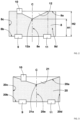
FIG. 10 is a schematic diagram of a mixing chamber of a ninth embodiment. - Hereinafter, an embodiment of the present invention will be described in detail with reference to the drawings.
-
FIG. 1 is a cross-sectional view conceptually showing apuncture repair kit 1 of the present embodiment. As shown inFIG. 1 , thepuncture repair kit 1 is suitably used, for example, for filling an object T, such as a punctured tire, with a puncture repair liquid R and compressed air A. Thepuncture repair kit 1 of the present embodiment includes abottle unit 2 and a compressor 3 for supplying the compressed air A to thebottle unit 2. - The
bottle unit 2 of the present embodiment includes a mixing device 4 for mixing the puncture repair liquid R and the compressed air A, and acontainer 5 for containing the puncture repair liquid R. The mixing device 4 includes, for example, anadapter member 6 attached to thecontainer 5, and a cap member 7 attached to theadapter member 6. - In such a
bottle unit 2, it is easy to attach the mixing device 4 and thecontainer 5 to each other, so that thebottle unit 2 serves to shorten the time required for puncture repair. In addition, the mixing device 4 can mix the puncture repair liquid R and the compressed air A in advance before filling the object T, thereby shortening the time required for puncture repair. The mixing device 4 is not limited to such a mode, and may be an integrally molded product in which theadapter member 6 and the cap member 7 are integrated. - The
container 5 has, for example, anopening portion 5a for containing the puncture repair liquid R inside thecontainer 5. Thecontainer 5 contains the puncture repair liquid R therein, for example, through theopening portion 5a. Theopening portion 5a has, for example, a film (not shown) for holding the contained puncture repair liquid R in an airtight manner. The mixing device 4 is preferably attached to theopening portion 5a of thecontainer 5. Such acontainer 5 eliminates the need to form a separate outlet for the puncture repair liquid R and serves to reduce the production cost. - The mixing device 4 includes, for example, a
mixing chamber 8 formed between theadapter member 6 and the cap member 7. Themixing chamber 8 of the present embodiment includes atop surface 8a which is located on an upper side when in use, that is, when the mixing device 4 is attached to thecontainer 5 and puncture repair is performed, and afloor surface 8b which is located on a lower side when in use. Themixing chamber 8 preferably includes aside surface 8c connecting thetop surface 8a and thefloor surface 8b. Such amixing chamber 8 is suitable for ensuring a space for mixing the puncture repair liquid R and the compressed air A in advance. - The
mixing chamber 8 has, for example, a circular column shape in which thetop surface 8a and thefloor surface 8b are circular. That is, theside surface 8c of themixing chamber 8 preferably has a cylindrical shape. Such amixing chamber 8 has no corners in theside surface 8c and is suitable for reducing the amount of residual matter in themixing chamber 8. - The
top surface 8a of themixing chamber 8 is formed, for example, by aseparation wall 6a of theadapter member 6. Thefloor surface 8b of themixing chamber 8 is formed, for example, by the cap member 7. Theside surface 8c of themixing chamber 8 is formed, for example, by theadapter member 6. Theside surface 8c of themixing chamber 8 may be formed, for example, by the cap member 7. Such amixing chamber 8 facilitates machining of thetop surface 8a and thefloor surface 8b and serves to reduce the production cost. - The mixing device 4 of the present embodiment includes a
first inlet 9 for supplying the compressed air A to themixing chamber 8, and asecond inlet 10 for supplying the puncture repair liquid R to themixing chamber 8. In such a mixing device 4, themixing chamber 8 can be repeatedly brought into a positive pressure state and a negative pressure state by pulsation of the compressed air A supplied from the compressor 3, thereby dripping the puncture repair liquid R from thesecond inlet 10 into themixing chamber 8 to produce a mixture. - At least a part of the mixture is, for example, an aerosol of the puncture repair liquid R and the compressed air A. That is, the
mixing chamber 8 of the present embodiment can aerosolize at least a part of the mixture. Such a mixture can be supplied with at least a part of the puncture repair liquid R as aerosol particles of about 1 to 100 µm. Accordingly, thepuncture repair kit 1 allows a punctured part to be efficiently repaired with a small amount of the puncture repair liquid R, and even if the object T is a tire in which a sound absorbing material, a sensor, etc., are placed, thepuncture repair kit 1 can reduce the influence on the sound absorbing material, the sensor, etc. - The puncture repair liquid R preferably contains at least glycol. Examples of glycol include ethylene glycol, 1,3-propanediol, and propylene glycol. Such a puncture repair liquid R is suitable for efficiently repairing a punctured part even when injected in a small amount as an aerosol into the object T such as a punctured tire.
- The mixing device 4 preferably includes an
outlet 11 for discharging the mixture of the puncture repair liquid R and the compressed air A from themixing chamber 8. Such a mixing device 4 allows the puncture repair liquid R and the compressed air A to smoothly flow thereinto and therefrom, and serves to shorten the time required for puncture repair. - The
first inlet 9 and theoutlet 11 are provided, for example, in the cap member 7. Thefirst inlet 9 and theoutlet 11 of the present embodiment are provided in thefloor surface 8b. Thesecond inlet 10 is provided, for example, in theseparation wall 6a of theadapter member 6. Thesecond inlet 10 of the present embodiment is provided in thetop surface 8a. - Such a mixing device 4 discharges the mixture of the compressed air A and the puncture repair liquid R dripped from the
second inlet 10 located on the upper side, through theoutlet 11 located on the lower side, and thus can inhibit the dripped puncture repair liquid R from remaining therein, thereby efficiently producing the mixture. -
FIG. 2 is a conceptual diagram of themixing chamber 8 of the present embodiment. For ease of understanding, themixing chamber 8 is colored inFIG. 2 , and the same applies toFIG. 3 and the subsequent drawings. As shown inFIG. 2 , the mixingchamber 8 of the present embodiment has amaximum section 8d where the distance between thetop surface 8a and thefloor surface 8b is the largest, and aminimum section 8e where this distance is the smallest. - Such a mixing
chamber 8 can provide directivity to the flow therein and can efficiently discharge the mixture of the puncture repair liquid R and the compressed air A therefrom. As a result, even if the mixture is at least partially aerosolized, the mixing device 4 of the present embodiment can quickly discharge the mixture through theoutlet 11, thereby suppressing aggregation of the mixture. Therefore, the mixing device 4 of the present embodiment allows puncture repair to be performed in a short time. - In a more preferable mode, in the mixing
chamber 8, the distance between thetop surface 8a and thefloor surface 8b gradually decreases from themaximum section 8d to theminimum section 8e. Such a mixingchamber 8 has no portion where the distance between thetop surface 8a and thefloor surface 8b locally fluctuates, so that there is no risk of the mixture remaining in the fluctuating portion. - A first height H1 which is the distance between the
top surface 8a and thefloor surface 8b at theminimum section 8e is preferably not greater than 60% of a second height H2 which is the distance between thetop surface 8a and thefloor surface 8b at themaximum section 8d. When the first height H1 is not greater than 60% of the second height H2, the mixture can easily flow along themaximum section 8d, thereby providing directivity to the flow inside the mixingchamber 8. From such a viewpoint, the first height H1 is more preferably not greater than 50% of the second height H2 and further preferably not greater than 35% of the second height H2. - In a plan view of the mixing
chamber 8, theminimum section 8e is preferably located between thefirst inlet 9 and theoutlet 11. Theminimum section 8e of the present embodiment is located on a straight line connecting the center of thefirst inlet 9 and the center of theoutlet 11. Such a mixingchamber 8 can provide directivity to the flow of the compressed air A from thefirst inlet 9 to theoutlet 11. - The
minimum section 8e of the present embodiment is located on a center line C of the mixingchamber 8 having a circular column shape. Such a mixingchamber 8 can make the flow therein symmetrical, and serves to make the flow smooth and shorten the residence time of the mixture in the mixingchamber 8. - The
minimum section 8e is formed by aprotrusion portion 12 which protrudes from at least one of thetop surface 8a and thefloor surface 8b, in the present embodiment, from thetop surface 8a, toward the interior of the mixingchamber 8. Theprotrusion portion 12 of the present embodiment is provided such that a part of thetop surface 8a protrudes toward the interior of the mixingchamber 8. Accordingly, the mixingchamber 8 has themaximum section 8d in a certain range from a peripheral portion along theside surface 8c. Such a mixingchamber 8 can ensure a certain internal volume, and serves to produce a large amount of the mixture in a short time. - The volume of the
protrusion portion 12 is preferably not less than 10% of the overall volume of the mixingchamber 8 including theprotrusion portion 12. When the volume of theprotrusion portion 12 is not less than 10% of the overall volume of the mixingchamber 8, the flow velocity inside the mixingchamber 8 can be increased, thereby shortening the residence time of the puncture repair liquid R in the mixingchamber 8. From such a viewpoint, the volume of theprotrusion portion 12 is more preferably not less than 25% of the overall volume of the mixingchamber 8 and further preferably not less than 35% of the overall volume of the mixingchamber 8. - The
protrusion portion 12 of the present embodiment has a conical shape having a mostprotruding vertex 12a. That is, thevertex 12a of theprotrusion portion 12 forms theminimum section 8e. Thevertex 12a of theprotrusion portion 12 of the present embodiment is located on the center line C of the mixingchamber 8 having a circular column shape. Such aprotrusion portion 12 facilitates machining of thetop surface 8a, can make the internal flow symmetrical with a simple configuration, and serves to disperse the mixture and inhibit the mixture from remaining in the mixingchamber 8. - As shown in
FIG. 1 , the mixingchamber 8 may have, for example, a plurality ofhemispherical recesses 13 formed on at least one of thetop surface 8a, thefloor surface 8b, and theside surface 8c. Such a plurality ofhemispherical recesses 13 serve to make the flow smooth and shorten the residence time of the mixture in the mixingchamber 8. - The
adapter member 6 has, for example, a breakingportion 14 which breaks the film (not shown) of theopening portion 5a when theadapter member 6 is attached to theopening portion 5a of thecontainer 5. Such a breakingportion 14 can break the film of theopening portion 5a when the mixing device 4 is attached to thecontainer 5, thereby allowing the puncture repair liquid R to be supplied to the mixingchamber 8. - The cap member 7 may be directly attached to the
opening portion 5a of thecontainer 5, for example, in an environment having a very low temperature at which it is difficult for the mixing device 4 to aerosolize at least a part of the mixture. The cap member 7 has asub breaking portion 15 which breaks the film of theopening portion 5a when the cap member 7 is attached to theopening portion 5a of thecontainer 5. Thesub breaking portion 15 is provided, for example, near the opening of theoutlet 11. - Such a
sub breaking portion 15 can break the film of theopening portion 5a when the cap member 7 is directly attached to thecontainer 5. In addition, thesub breaking portion 15 serves to reduce the flow path resistance in the mixingchamber 8 when the cap member 7 is attached to theadapter member 6 as the mixing device 4. - The
adapter member 6 is screwed to both theopening portion 5a of thecontainer 5 and the cap member 7, for example. The space between theadapter member 6 and theopening portion 5a is preferably sealed by a sealingmember 16. The space between theadapter member 6 and the cap member 7 is sealed, for example, by asub sealing member 17. Such anadapter member 6 is easily attached to thecontainer 5 and to the cap member 7, and has excellent airtightness after being attached. -
FIG. 3 is a schematic diagram of a mixingchamber 20 of a second embodiment. The same components as those in the above-described embodiment are designated by the same reference characters, and the description thereof is omitted. As shown inFIG. 3 , the mixingchamber 20 of the second embodiment includes atop surface 20a which is located on an upper side when in use, afloor surface 20b which is located on a lower side when in use, and aside surface 20c connecting thetop surface 20a and thefloor surface 20b. Similar to the above-describedmixing chamber 8, the mixingchamber 20 of the second embodiment has a circular column shape in which thetop surface 20a and thefloor surface 20b are circular, and theside surface 20c has a cylindrical shape. - As in the above-described
mixing chamber 8, in the mixingchamber 20 of the second embodiment, the distance between thetop surface 20a and thefloor surface 20b gradually decreases from amaximum section 20d where this distance is the largest, to aminimum section 20e where this distance is the smallest. Similar to the above-describedminimum section 8e, theminimum section 20e of the second embodiment is located on a center line C, of the mixingchamber 20 having a circular column shape, between thefirst inlet 9 and theoutlet 11. Such a mixingchamber 20 can provide directivity to the flow of the compressed air A from thefirst inlet 9 to theoutlet 11. - Similar to the above-described
minimum section 8e, theminimum section 20e of the second embodiment is formed by aprotrusion portion 21 which protrudes from thetop surface 20a toward the interior of the mixingchamber 20. Theprotrusion portion 21 of the second embodiment is provided such that the entiretop surface 20a protrudes toward the interior of the mixingchamber 20. Accordingly, the mixingchamber 20 has themaximum section 20d at a peripheral portion along theside surface 20c. Such a mixingchamber 20 can make the change of the internal volume thereof smooth, and serves to inhibit the mixture from remaining therein. - Similar to the above-described
protrusion portion 12, theprotrusion portion 21 of the second embodiment has a conical shape having a mostprotruding vertex 21a. Thevertex 21a of theprotrusion portion 21 of the second embodiment is located on the center line C of the mixingchamber 20 having a circular column shape. Such aprotrusion portion 21 facilitates machining of thetop surface 20a, can make the internal flow symmetrical with a simple configuration, and serves to disperse the mixture and inhibit the mixture from remaining therein. -
FIG. 4 is a schematic diagram of a mixingchamber 25 of a third embodiment. The same components as those in the above-described embodiments are designated by the same reference characters, and the description thereof is omitted. As shown inFIG. 4 , the mixingchamber 25 of the third embodiment includes atop surface 25a which is located on an upper side when in use, afloor surface 25b which is located on a lower side when in use, and aside surface 25c connecting thetop surface 25a and thefloor surface 25b. Similar to the above-describedmixing chamber 8, the mixingchamber 25 of the third embodiment has a circular column shape in which thetop surface 25a and thefloor surface 25b are circular, and theside surface 25c has a cylindrical shape. - As in the above-described
mixing chamber 8, in the mixingchamber 25 of the third embodiment, the distance between thetop surface 25a and thefloor surface 25b gradually decreases from amaximum section 25d where this distance is the largest, to aminimum section 25e where this distance is the smallest. Similar to the above-describedminimum section 8e, theminimum section 25e of the third embodiment is located on a straight line, connecting the center of thefirst inlet 9 and the center of theoutlet 11, between thefirst inlet 9 and theoutlet 11. - The
minimum section 25e of the third embodiment is located on thefirst inlet 9 side with respect to a center line C of the mixingchamber 25 having a circular column shape. The position of theminimum section 25e is not limited to such a position, and can be set to any position according to the puncture repair liquid R to be dripped and the compressor 3. Such a mixingchamber 25 can be set to a shape that is optimum to make the flow smooth and shorten the residence time of the mixture in the mixingchamber 8. - Similar to the above-described
minimum section 8e, theminimum section 25e of the third embodiment is formed by aprotrusion portion 26 which protrudes from thetop surface 25a toward the interior of the mixingchamber 25. Similar to the above-describedprotrusion portion 21, theprotrusion portion 26 of the third embodiment is provided such that the entiretop surface 25a protrudes toward the interior of the mixingchamber 25. Accordingly, the mixingchamber 25 has themaximum section 25d at a peripheral portion along theside surface 25c. Such a mixingchamber 25 serves to set theminimum section 25e at a position that is optimum to make the flow smooth. - The
protrusion portion 26 of the third embodiment has an oblique conical shape having a mostprotruding vertex 26a. Here, the oblique cone shape is a type of conical shape in which thevertex 26a is not located on the center of a bottom surface. Thevertex 26a of theprotrusion portion 26 of the third embodiment is located at theminimum section 25e of the mixingchamber 25. Such aprotrusion portion 26 facilitates machining of thetop surface 25a, can make the internal flow symmetrical with a simple configuration, and serves to disperse the mixture and inhibit the mixture from remaining therein. -
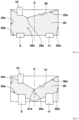
FIG. 5 is a schematic diagram of a mixingchamber 30 of a fourth embodiment. The same components as those in the above-described embodiments are designated by the same reference characters, and the description thereof is omitted. As shown inFIG. 5 , the mixingchamber 30 of the fourth embodiment includes atop surface 30a which is located on an upper side when in use, afloor surface 30b which is located on a lower side when in use, and aside surface 30c connecting thetop surface 30a and thefloor surface 30b. Similar to the above-describedmixing chamber 8, the mixingchamber 30 of the fourth embodiment has a circular column shape in which thetop surface 30a and thefloor surface 30b are circular, and theside surface 30c has a cylindrical shape. - As in the above-described
mixing chamber 8, in the mixingchamber 30 of the fourth embodiment, the distance between thetop surface 30a and thefloor surface 30b gradually decreases from amaximum section 30d where this distance is the largest, to aminimum section 30e where this distance is the smallest. Similar to the above-describedminimum section 8e, theminimum section 30e of the fourth embodiment is located on a center line C, of the mixingchamber 30 having a circular column shape, between thefirst inlet 9 and theoutlet 11. Such a mixingchamber 30 can provide directivity to the flow of the compressed air A from thefirst inlet 9 to theoutlet 11. - Similar to the above-described
minimum section 8e, theminimum section 30e of the fourth embodiment is formed by aprotrusion portion 31 which protrudes from thetop surface 30a toward the interior of the mixingchamber 30. Similar to the above-describedprotrusion portion 21, theprotrusion portion 31 of the fourth embodiment is provided such that the entiretop surface 30a protrudes toward the interior of the mixingchamber 30. - The
floor surface 30b of the fourth embodiment is recessed in the protruding direction of theprotrusion portion 31. Theminimum section 30e of the fourth embodiment is formed on the center line C of the mixingchamber 30 by making the inclination angle of theprotrusion portion 31 and the inclination angle of thefloor surface 30b different from each other. Accordingly, the mixingchamber 30 has themaximum section 30d at a peripheral portion along theside surface 30c. Such a mixingchamber 30 can control the directivity of the flow with both thetop surface 30a and thefloor surface 30b. - Similar to the above-described
protrusion portion 21, theprotrusion portion 31 of the fourth embodiment has a conical shape having a mostprotruding vertex 31a. Thevertex 31a of theprotrusion portion 31 of the fourth embodiment is located on the center line C of the mixingchamber 30 having a circular column shape. Such aprotrusion portion 31 facilitates machining of thetop surface 30a, can make the internal flow symmetrical with a simple configuration, and serves to disperse the mixture and inhibit the mixture from remaining therein. -
FIG. 6 is a schematic diagram of a mixingchamber 35 of a fifth embodiment. The same components as those in the above-described embodiments are designated by the same reference characters, and the description thereof is omitted. As shown inFIG. 6 , the mixingchamber 35 of the fifth embodiment includes atop surface 35a which is located on an upper side when in use, afloor surface 35b which is located on a lower side when in use, and aside surface 35c connecting thetop surface 35a and thefloor surface 35b. Similar to the above-describedmixing chamber 8, the mixingchamber 35 of the fifth embodiment has a circular column shape in which thetop surface 35a and thefloor surface 35b are circular, and theside surface 35c has a cylindrical shape. - As in the above-described
mixing chamber 8, in the mixingchamber 35 of the fifth embodiment, the distance between thetop surface 35a and thefloor surface 35b gradually decreases from amaximum section 35d where this distance is the largest, to aminimum section 35e where this distance is the smallest. Similar to the above-describedminimum section 8e, theminimum section 35e of the fifth embodiment is located on a center line C, of the mixingchamber 35 having a circular column shape, between thefirst inlet 9 and theoutlet 11. Such a mixingchamber 35 can provide directivity to the flow of the compressed air A from thefirst inlet 9 to theoutlet 11. - Similar to the above-described
minimum section 8e, theminimum section 35e of the fifth embodiment is formed by aprotrusion portion 36 which protrudes from thetop surface 35a toward the interior of the mixingchamber 35. Similar to the above-describedprotrusion portion 21, theprotrusion portion 36 of the fifth embodiment is provided such that the entiretop surface 35a protrudes toward the interior of the mixingchamber 35. Accordingly, the mixingchamber 35 has themaximum section 35d at a peripheral portion along theside surface 35c. Such a mixingchamber 35 can make the change of the internal volume thereof smooth, and serves to inhibit the mixture from remaining therein. - The
protrusion portion 36 of the fifth embodiment has a hemispherically protruding dome shape. Avertex 36a of theprotrusion portion 36 of the fifth embodiment is located on the center line C of the mixingchamber 35 having a circular column shape. Such aprotrusion portion 36 facilitates machining of thetop surface 35a, can make the internal flow symmetrical with a simple configuration, and serves to disperse the mixture and inhibit the mixture from remaining therein. -
FIG. 7 is a schematic diagram of a mixingchamber 40 of a sixth embodiment. The same components as those in the above-described embodiments are designated by the same reference characters, and the description thereof is omitted. As shown inFIG. 7 , the mixingchamber 40 of the sixth embodiment includes atop surface 40a which is located on an upper side when in use, afloor surface 40b which is located on a lower side when in use, and aside surface 40c connecting thetop surface 40a and thefloor surface 40b. Similar to the above-describedmixing chamber 8, the mixingchamber 40 of the sixth embodiment has a circular column shape in which thetop surface 40a and thefloor surface 40b are circular, and theside surface 40c has a cylindrical shape. - As in the above-described
mixing chamber 8, in the mixingchamber 40 of the sixth embodiment, the distance between thetop surface 40a and thefloor surface 40b gradually decreases from amaximum section 40d where this distance is the largest, to aminimum section 40e where this distance is the smallest. Similar to the above-describedminimum section 8e, theminimum section 40e of the sixth embodiment is located between thefirst inlet 9 and theoutlet 11. Such a mixingchamber 40 can provide directivity to the flow of the compressed air A from thefirst inlet 9 to theoutlet 11. - Similar to the above-described
minimum section 8e, theminimum section 40e of the sixth embodiment is formed by aprotrusion portion 41 which protrudes from thetop surface 40a toward the interior of the mixingchamber 40. Similar to the above-describedprotrusion portion 21, theprotrusion portion 41 of the sixth embodiment is provided such that the entiretop surface 40a protrudes toward the interior of the mixingchamber 40. Accordingly, the mixingchamber 40 has themaximum section 40d at a peripheral portion along theside surface 40c. Such a mixingchamber 40 can make the change of the internal volume thereof smooth, and serves to inhibit the mixture from remaining therein. - The
protrusion portion 41 of the sixth embodiment has a truncated cone shape having a most protrudingtop portion 41a. Thetop portion 41a of theprotrusion portion 41 of the sixth embodiment has a circular shape having a center on a center line C of the mixingchamber 40 having a circular column shape. Such aprotrusion portion 41 facilitates machining of thetop surface 40a, can make the internal flow symmetrical with a simple configuration, and serves to disperse the mixture and inhibit the mixture from remaining therein. - The
top portion 41a of theprotrusion portion 41 of the sixth embodiment has arecess 41b which is recessed in a direction opposite to the protruding direction of theprotrusion portion 41. Such aprotrusion portion 41 can increase the internal volume of the mixingchamber 40, and serves to produce a large amount of the mixture in a short time. -
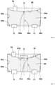
FIG. 8 is a schematic diagram of a mixingchamber 45 of a seventh embodiment. The same components as those in the above-described embodiments are designated by the same reference characters, and the description thereof is omitted. As shown inFIG. 8 , the mixingchamber 45 of the seventh embodiment includes atop surface 45a which is located on an upper side when in use, afloor surface 45b which is located on a lower side when in use, and aside surface 45c connecting thetop surface 45a and thefloor surface 45b. Similar to the above-describedmixing chamber 8, the mixingchamber 45 of the seventh embodiment has a circular column shape in which thetop surface 45a and thefloor surface 45b are circular, and theside surface 45c has a cylindrical shape. - As in the above-described
mixing chamber 8, in the mixingchamber 45 of the seventh embodiment, the distance between thetop surface 45a and thefloor surface 45b gradually decreases from amaximum section 45d where this distance is the largest, to aminimum section 45e where this distance is the smallest. Similar to the above-describedminimum section 8e, theminimum section 45e of the seventh embodiment is located on a center line C, of the mixingchamber 45 having a circular column shape, between thefirst inlet 9 and theoutlet 11. Such a mixingchamber 45 can provide directivity to the flow of the compressed air A from thefirst inlet 9 to theoutlet 11. - The
minimum section 45e of the seventh embodiment is formed by aprotrusion portion 46 which protrudes from thefloor surface 45b toward the interior of the mixingchamber 45. Theprotrusion portion 46 of the seventh embodiment is provided such that theentire floor surface 45b protrudes toward the interior of the mixingchamber 45. Accordingly, the mixingchamber 45 has themaximum section 45d at a peripheral portion along theside surface 45c. Such a mixingchamber 45 can make the change of the internal volume thereof smooth, and serves to inhibit the mixture from remaining therein. - The
protrusion portion 46 of the seventh embodiment has a conical shape having a mostprotruding vertex 46a. Thevertex 46a of theprotrusion portion 46 of the seventh embodiment is located on the center line C of the mixingchamber 45 having a circular column shape. Such aprotrusion portion 46 facilitates machining of thefloor surface 45b, can make the internal flow symmetrical with a simple configuration, and serves to disperse the mixture and inhibit the mixture from remaining therein. -
FIG. 9 is a schematic diagram of a mixingchamber 50 of an eighth embodiment. The same components as those in the above-described embodiments are designated by the same reference characters, and the description thereof is omitted. As shown inFIG. 9 , the mixingchamber 50 of the eighth embodiment includes atop surface 50a which is located on an upper side when in use, afloor surface 50b which is located on a lower side when in use, and aside surface 50c connecting thetop surface 50a and thefloor surface 50b. Similar to the above-describedmixing chamber 8, the mixingchamber 50 of the eighth embodiment has a circular column shape in which thetop surface 50a and thefloor surface 50b are circular, and theside surface 50c has a cylindrical shape. - As in the above-described
mixing chamber 8, in the mixingchamber 50 of the eighth embodiment, the distance between thetop surface 50a and thefloor surface 50b gradually decreases from amaximum section 50d where this distance is the largest, to aminimum section 50e where this distance is the smallest. Similar to the above-describedminimum section 8e, theminimum section 50e of the eighth embodiment is located on a center line C, of the mixingchamber 50 having a circular column shape, between thefirst inlet 9 and theoutlet 11. Such a mixingchamber 50 can provide directivity to the flow of the compressed air A from thefirst inlet 9 to theoutlet 11. - Similar to the above-described
minimum section 45e, theminimum section 50e of the eighth embodiment is formed by aprotrusion portion 51 which protrudes from thefloor surface 50b toward the interior of the mixingchamber 50. Similar to the above-describedprotrusion portion 46, theprotrusion portion 51 of the eighth embodiment is provided such that theentire floor surface 50b protrudes toward the interior of the mixingchamber 50. - The
top surface 50a of the eighth embodiment is recessed in the protruding direction of theprotrusion portion 51. Theminimum section 50e of the eighth embodiment is formed on the center line C of the mixingchamber 50 by making the inclination angle of theprotrusion portion 51 and the inclination angle of thetop surface 50a different from each other. Accordingly, the mixingchamber 50 has themaximum section 50d at a peripheral portion along theside surface 50c. Such a mixingchamber 50 can control the directivity of the flow with both thetop surface 50a and thefloor surface 50b. - Similar to the above-described
protrusion portion 46, theprotrusion portion 51 of the eighth embodiment has a conical shape having a mostprotruding vertex 51a. Thevertex 51a of theprotrusion portion 51 of the eighth embodiment is located on the center line C of the mixingchamber 50 having a circular column shape. Such aprotrusion portion 51 facilitates machining of thefloor surface 50b, can make the internal flow symmetrical with a simple configuration, and serves to disperse the mixture and inhibit the mixture from remaining therein. -
FIG. 10 is a schematic diagram of a mixingchamber 55 of a ninth embodiment. The same components as those in the above-described embodiments are designated by the same reference characters, and the description thereof is omitted. As shown inFIG. 10 , the mixingchamber 55 of the ninth embodiment includes atop surface 55a which is located on an upper side when in use, afloor surface 55b which is located on a lower side when in use, and aside surface 55c connecting thetop surface 55a and thefloor surface 55b. Similar to the above-describedmixing chamber 8, the mixingchamber 55 of the ninth embodiment has a circular column shape in which thetop surface 55a and thefloor surface 55b are circular, and theside surface 55c has a cylindrical shape. - As in the above-described
mixing chamber 8, in the mixingchamber 55 of the ninth embodiment, the distance between thetop surface 55a and thefloor surface 55b gradually decreases from amaximum section 55d where this distance is the largest, to aminimum section 55e where this distance is the smallest. Similar to the above-describedminimum section 8e, theminimum section 55e of the ninth embodiment is located on a center line C, of the mixingchamber 55 having a circular column shape, between thefirst inlet 9 and theoutlet 11. Such a mixingchamber 55 can provide directivity to the flow of the compressed air A from thefirst inlet 9 to theoutlet 11. - The
minimum section 55e of the ninth embodiment is formed by aprotrusion portion 56 which protrudes from thetop surface 55a and thefloor surface 55b toward the interior of the mixingchamber 55. Theprotrusion portion 56 of the ninth embodiment is provided such that both the entiretop surface 55a and theentire floor surface 55b project toward the interior of the mixingchamber 55. Accordingly, the mixingchamber 55 has themaximum section 55d at a peripheral portion along theside surface 55c. Such a mixingchamber 55 can make the change of the internal volume thereof smooth, and serves to inhibit the mixture from remaining therein. - The
protrusion portion 56 of the ninth embodiment includes afirst protrusion portion 56A provided at thetop surface 55a, and asecond protrusion portion 56B provided at thefloor surface 55b. Such a mixingchamber 55 can control the directivity of the flow with both thefirst protrusion portion 56A at thetop surface 55a and thesecond protrusion portion 56B at thefloor surface 55b. - The
first protrusion portion 56A of the ninth embodiment has a conical shape having a mostprotruding vertex 56a. Thesecond protrusion portion 56B of the ninth embodiment has a conical shape having a mostprotruding vertex 56b. Each of thevertex 56a of thefirst protrusion portion 56A and thevertex 56b of thesecond protrusion portion 56B of the ninth embodiment is located on the center line C of the mixingchamber 55 having a circular column shape. Such aprotrusion portion 56 facilitates machining of thetop surface 55a and thefloor surface 55b, can make the internal flow symmetrical with a simple configuration, and serves to disperse the mixture and inhibit the mixture from remaining therein. - The
first protrusion portion 56A and thesecond protrusion portion 56B of theprotrusion portion 56 of the ninth embodiment have the same shape, but theprotrusion portion 56 of the ninth embodiment is not limited to such a mode. The shape of theprotrusion portion 56 may be, for example, a shape in which the heights of thefirst protrusion portion 56A and thesecond protrusion portion 56B are different from each other, or a shape in which the positions and shapes of thevertices - Although the particularly preferred embodiments of the present invention have been described in detail above, the present invention is not limited to the above-described embodiments, and various modifications can be made to implement the present invention.
- The present invention is as follows.
- A mixing device for mixing a puncture repair liquid and compressed air, the mixing device including:
- a mixing chamber including a top surface located on an upper side when in use and a floor surface located on a lower side when in use;
- a first inlet for supplying the compressed air to the mixing chamber;
- a second inlet for supplying the puncture repair liquid to the mixing chamber; and
- an outlet for discharging a mixture of the puncture repair liquid and the compressed air from the mixing chamber, wherein
- the mixing chamber has a maximum section where a distance between the top surface and the floor surface is the largest, and a minimum section where the distance is the smallest.
- The mixing device according to
Present Invention 1, wherein the minimum section is formed by a protrusion portion which protrudes from at least one of the top surface and the floor surface toward an interior of the mixing chamber. - The mixing device according to
Present Invention 2, wherein the protrusion portion has a conical shape having a most protruding vertex. - The mixing device according to
Present Invention 2, wherein the protrusion portion has a hemispherically protruding dome shape. - The mixing device according to
Present Invention 2, wherein the protrusion portion has a truncated cone shape having a most protruding top portion. - The mixing device according to
Present Invention 5, wherein the top portion has a recess which is recessed in a direction opposite to a protruding direction thereof. - The mixing device according to any one of
Present Inventions 2 to 6, wherein the protrusion portion is provided at the top surface. - The mixing device according to any one of
Present Inventions 2 to 6, wherein the protrusion portion is provided at the floor surface. - The mixing device according to any one of
Present Inventions 2 to 6, wherein the protrusion portion is provided at each of the top surface and the floor surface. - The mixing device according to any one of
Present Inventions 1 to 9, wherein, in the mixing chamber, the distance between the top surface and the floor surface gradually decreases from the maximum section to the minimum section. - The mixing device according to any one of
Present Inventions 1 to 10, wherein the minimum section is located between the first inlet and the outlet in a plan view of the mixing chamber. - The mixing device according to any one of
Present Inventions 1 to 11, wherein the mixing chamber has a circular column shape in which the top surface and the floor surface are circular. - The mixing device according to
Present Invention 12, wherein the minimum section is located on a center line of the mixing chamber. - A bottle unit including:
- the mixing device according to any one of
Present Inventions 1 to 13; and - a container for containing the puncture repair liquid, wherein
- the container has an opening portion for containing the puncture repair liquid inside the container, and
- the mixing device is attached to the opening portion.
- A puncture repair kit including:
- the bottle unit according to
Present Invention 14; and - a compressor for supplying the compressed air.
Claims (15)
- A mixing device (4) for mixing a puncture repair liquid (R) and compressed air (A), the mixing device (4) comprising:a mixing chamber (8, 20, 25, 30, 35, 40, 45, 50, 55) including a top surface (8a, 20a, 25a, 30a, 35a, 40a, 45a, 50a, 55a) located on an upper side when in use and a floor surface (8b, 20b, 25b, 30b, 35b, 40b, 45b, 50b, 55b) located on a lower side when in use;a first inlet (9) for supplying the compressed air (A) to the mixing chamber (8, 20, 25, 30, 35, 40, 45, 50, 55);a second inlet (10) for supplying the puncture repair liquid (R) to the mixing chamber (8, 20, 25, 30, 35, 40, 45, 50, 55); andan outlet (11) for discharging a mixture of the puncture repair liquid (R) and the compressed air (A) from the mixing chamber (8, 20, 25, 30, 35, 40, 45, 50, 55), whereinthe mixing chamber (8, 20, 25, 30, 35, 40, 45, 50, 55) has a maximum section (8d, 20d, 25d, 30d, 35d, 40d, 45d, 50d, 55d) where a distance between the top surface (8a, 20a, 25a, 30a, 35a, 40a, 45a, 50a, 55a) and the floor surface (8b, 20b, 25b, 30b, 35b, 40b, 45b, 50b, 55b) is the largest, and a minimum section (8e, 20e, 25e, 30e, 35e, 40e, 45e, 50e, 55e) where the distance is the smallest.
- The mixing device (4) according to claim 1, wherein the minimum section (8e, 20e, 25e, 30e, 35e, 40e, 45e, 50e, 55e) is formed by a protrusion portion(12, 21, 26, 31, 36, 41, 46, 51, 56) which protrudes from at least one of the top surface (8a, 20a, 25a, 30a, 35a, 40a, 45a, 50a, 55a) and the floor surface (8b, 20b, 25b, 30b, 35b, 40b, 45b, 50b, 55b) toward an interior of the mixing chamber (8, 20, 25, 30, 35, 40, 45, 50, 55).
- The mixing device (4) according to claim 2, wherein the protrusion portion (12, 21, 26, 31, 46, 51, 56) has a conical shape having a most protruding vertex (12a, 21a, 26a, 31a, 46a, 51a, 56a).
- The mixing device (4) according to claim 2, wherein the protrusion portion (36) has a hemispherically protruding dome shape.
- The mixing device (4) according to claim 2, wherein the protrusion portion (41) has a truncated cone shape having a most protruding top portion (41a).
- The mixing device (4) according to claim 5, wherein the top portion (41a) has a recess (41b) which is recessed in a direction opposite to a protruding direction thereof.
- The mixing device (4) according to any one of claims 2 to 6, wherein the protrusion portion (12, 21, 26, 31, 36, 41, 46, 51, 56) is provided at the top surface (8a, 20a, 25a, 30a, 35a, 40a, 45a, 50a, 55a).
- The mixing device (4) according to any one of claims 2 to 6, wherein the protrusion portion (46, 51, 56) is provided at the floor surface (45b, 50b, 55b).
- The mixing device (4) according to any one of claims 2 to 6, wherein the protrusion portion (12, 21, 26, 31, 36, 41, 46, 51, 56) is provided at each of the top surface (8a, 20a, 25a, 30a, 35a, 40a, 45a, 50a, 55a) and the floor surface (8b, 20b, 25b, 30b, 35b, 40b, 45b, 50b, 55b).
- The mixing device (4) according to any one of claims 1 to 9, wherein, in the mixing chamber (8, 20, 25, 30, 35, 40, 45, 50, 55), the distance between the top surface (8a, 20a, 25a, 30a, 35a, 40a, 45a, 50a, 55a) and the floor surface (8b, 20b, 25b, 30b, 35b, 40b, 45b, 50b, 55b) gradually decreases from the maximum section (8d, 20d, 25d, 30d, 35d, 40d, 45d, 50d, 55d) to the minimum section (8e, 20e, 25e, 30e, 35e, 40e, 45e, 50e, 55e).
- The mixing device (4) according to any one of claims 1 to 10, wherein the minimum section (8e, 20e, 25e, 30e, 35e, 40e, 45e, 50e, 55e) is located between the first inlet (9) and the outlet (11) in a plan view of the mixing chamber (8, 20, 25, 30, 35, 40, 45, 50, 55).
- The mixing device (4) according to any one of claims 1 to 11, wherein the mixing chamber (8, 20, 25, 30, 35, 40, 45, 50, 55) has a circular column shape in which the top surface (8a, 20a, 25a, 30a, 35a, 40a, 45a, 50a, 55a) and the floor surface (8b, 20b, 25b, 30b, 35b, 40b, 45b, 50b, 55b) are circular.
- The mixing device (4) according to claim 12, wherein the minimum section (8e, 20e, 30e, 35e, 40e, 45e, 50e, 55e) is located on a center line (C) of the mixing chamber (8, 20, 30, 35, 40, 45, 50, 55).
- A bottle unit (2) comprising:the mixing device (4) according to any one of claims 1 to 13; anda container (5) for containing the puncture repair liquid (R), whereinthe container (5) has an opening portion (5a) for containing the puncture repair liquid (R) inside the container (5), andthe mixing device (4) is attached to the opening portion (5a).
- A puncture repair kit (1) comprising:the bottle unit (2) according to claim 14; anda compressor (3) for supplying the compressed air (A).
Applications Claiming Priority (1)
| Application Number | Priority Date | Filing Date | Title |
|---|---|---|---|
| JP2023050286A JP2024139380A (en) | 2023-03-27 | 2023-03-27 | Mixing device, bottle unit and puncture repair kit |
Publications (1)
| Publication Number | Publication Date |
|---|---|
| EP4438165A1 true EP4438165A1 (en) | 2024-10-02 |
Family
ID=89984682
Family Applications (1)
| Application Number | Title | Priority Date | Filing Date |
|---|---|---|---|
| EP24158289.9A Pending EP4438165A1 (en) | 2023-03-27 | 2024-02-19 | Mixing device, bottle unit, and puncture repair kit |
Country Status (3)
| Country | Link |
|---|---|
| EP (1) | EP4438165A1 (en) |
| JP (1) | JP2024139380A (en) |
| CN (1) | CN118700755A (en) |
Citations (5)
| Publication number | Priority date | Publication date | Assignee | Title |
|---|---|---|---|---|
| US20050189081A1 (en) * | 2003-12-23 | 2005-09-01 | M-I L.L.C. | Device and methodology for improved mixing of liquids and solids |
| JP2006116365A (en) * | 2004-09-27 | 2006-05-11 | Nanoplanet Kenkyusho:Kk | Swivel type fine bubble generator and bubble generation method |
| JP2011167675A (en) * | 2010-02-22 | 2011-09-01 | Nanoplanet Corp | Device for generating whirling mist and method of generating whirling mist |
| JP2017056662A (en) | 2015-09-17 | 2017-03-23 | 住友ゴム工業株式会社 | Puncture repair kit |
| DE102019217775A1 (en) * | 2019-11-19 | 2021-05-20 | Continental Reifen Deutschland Gmbh | Device for transporting compressed air and / or sealant into a pneumatic vehicle tire and portable / transportable system for sealing and inflating pneumatic vehicle tires |
-
2023
- 2023-03-27 JP JP2023050286A patent/JP2024139380A/en active Pending
-
2024
- 2024-02-02 CN CN202410149826.8A patent/CN118700755A/en active Pending
- 2024-02-19 EP EP24158289.9A patent/EP4438165A1/en active Pending
Patent Citations (5)
| Publication number | Priority date | Publication date | Assignee | Title |
|---|---|---|---|---|
| US20050189081A1 (en) * | 2003-12-23 | 2005-09-01 | M-I L.L.C. | Device and methodology for improved mixing of liquids and solids |
| JP2006116365A (en) * | 2004-09-27 | 2006-05-11 | Nanoplanet Kenkyusho:Kk | Swivel type fine bubble generator and bubble generation method |
| JP2011167675A (en) * | 2010-02-22 | 2011-09-01 | Nanoplanet Corp | Device for generating whirling mist and method of generating whirling mist |
| JP2017056662A (en) | 2015-09-17 | 2017-03-23 | 住友ゴム工業株式会社 | Puncture repair kit |
| DE102019217775A1 (en) * | 2019-11-19 | 2021-05-20 | Continental Reifen Deutschland Gmbh | Device for transporting compressed air and / or sealant into a pneumatic vehicle tire and portable / transportable system for sealing and inflating pneumatic vehicle tires |
Also Published As
| Publication number | Publication date |
|---|---|
| CN118700755A (en) | 2024-09-27 |
| JP2024139380A (en) | 2024-10-09 |
Similar Documents
| Publication | Publication Date | Title |
|---|---|---|
| KR950009536B1 (en) | A mixing chamber for mixing a gaseous and a liquid component | |
| US20230173814A1 (en) | Ink bottle and bottle set | |
| EP1507710B1 (en) | Aerosol dispenser for mixing and dispensing multiple fluid products | |
| US4165825A (en) | Tiltable valve member for pressurized containers | |
| CN106687217A (en) | spray insert | |
| EP2907666A2 (en) | Tank unit and liquid ejecting system having tank unit | |
| JP2021115394A (en) | Nozzle for liquid container and liquid container | |
| US12070916B2 (en) | Mixing device, bottle unit, and puncture repair kit | |
| CN100408199C (en) | Liquid Injection Adapter and Liquid Supply Reservoir | |
| TW202146304A (en) | Dispensation devices and methods of manufacture and use thereof | |
| US20230321932A1 (en) | Mixing device, bottle unit, and puncture repair kit | |
| CN112888518B (en) | Atomizing nozzle, atomizing device, method for producing metal powder, and metal powder | |
| CN118700755A (en) | Mixing device, bottle unit and puncture repair kit | |
| EP4438166A1 (en) | Mixing device, bottle unit, and puncture repair kit | |
| JP2006213350A (en) | Nozzle hole structure for dripping, dripping nozzle having this nozzle hole structure | |
| EP4438279B1 (en) | Bottle set and puncture repair kit | |
| KR100710962B1 (en) | Inner plug of medical fluid container | |
| CN109963794A (en) | Valve arrangement for closing pressurized tanks in equipment | |
| US20050279761A1 (en) | Hermetically sealed container with drop control | |
| JP5364136B2 (en) | Punk repair kit | |
| JP5357813B2 (en) | Cap unit | |
| EP4527603A1 (en) | Mixing device, bottle unit, and puncture repair kit | |
| JP2018058593A (en) | Discharge container | |
| EP4520513A1 (en) | Mixing device, mixing method, bottle unit, and puncture repair kit | |
| JPH11189251A (en) | Two pack-liquid extruding container |
Legal Events
| Date | Code | Title | Description |
|---|---|---|---|
| PUAI | Public reference made under article 153(3) epc to a published international application that has entered the european phase |
Free format text: ORIGINAL CODE: 0009012 |
|
| STAA | Information on the status of an ep patent application or granted ep patent |
Free format text: STATUS: THE APPLICATION HAS BEEN PUBLISHED |
|
| AK | Designated contracting states |
Kind code of ref document: A1 Designated state(s): AL AT BE BG CH CY CZ DE DK EE ES FI FR GB GR HR HU IE IS IT LI LT LU LV MC ME MK MT NL NO PL PT RO RS SE SI SK SM TR |
|
| STAA | Information on the status of an ep patent application or granted ep patent |
Free format text: STATUS: REQUEST FOR EXAMINATION WAS MADE |
|
| 17P | Request for examination filed |
Effective date: 20250227 |
|
| P01 | Opt-out of the competence of the unified patent court (upc) registered |
Free format text: CASE NUMBER: APP_12417/2025 Effective date: 20250313 |
|
| GRAP | Despatch of communication of intention to grant a patent |
Free format text: ORIGINAL CODE: EPIDOSNIGR1 |
|
| STAA | Information on the status of an ep patent application or granted ep patent |
Free format text: STATUS: GRANT OF PATENT IS INTENDED |