EP4437879A1 - Atomizer and heating member thereof - Google Patents
Atomizer and heating member thereof Download PDFInfo
- Publication number
- EP4437879A1 EP4437879A1 EP23739980.3A EP23739980A EP4437879A1 EP 4437879 A1 EP4437879 A1 EP 4437879A1 EP 23739980 A EP23739980 A EP 23739980A EP 4437879 A1 EP4437879 A1 EP 4437879A1
- Authority
- EP
- European Patent Office
- Prior art keywords
- liquid
- heating
- heating member
- atomizer
- capillary element
- Prior art date
- Legal status (The legal status is an assumption and is not a legal conclusion. Google has not performed a legal analysis and makes no representation as to the accuracy of the status listed.)
- Pending
Links
Images



Classifications
-
- A—HUMAN NECESSITIES
- A24—TOBACCO; CIGARS; CIGARETTES; SIMULATED SMOKING DEVICES; SMOKERS' REQUISITES
- A24F—SMOKERS' REQUISITES; MATCH BOXES; SIMULATED SMOKING DEVICES
- A24F40/00—Electrically operated smoking devices; Component parts thereof; Manufacture thereof; Maintenance or testing thereof; Charging means specially adapted therefor
- A24F40/40—Constructional details, e.g. connection of cartridges and battery parts
-
- A—HUMAN NECESSITIES
- A24—TOBACCO; CIGARS; CIGARETTES; SIMULATED SMOKING DEVICES; SMOKERS' REQUISITES
- A24F—SMOKERS' REQUISITES; MATCH BOXES; SIMULATED SMOKING DEVICES
- A24F40/00—Electrically operated smoking devices; Component parts thereof; Manufacture thereof; Maintenance or testing thereof; Charging means specially adapted therefor
- A24F40/10—Devices using liquid inhalable precursors
-
- A—HUMAN NECESSITIES
- A24—TOBACCO; CIGARS; CIGARETTES; SIMULATED SMOKING DEVICES; SMOKERS' REQUISITES
- A24F—SMOKERS' REQUISITES; MATCH BOXES; SIMULATED SMOKING DEVICES
- A24F40/00—Electrically operated smoking devices; Component parts thereof; Manufacture thereof; Maintenance or testing thereof; Charging means specially adapted therefor
- A24F40/40—Constructional details, e.g. connection of cartridges and battery parts
- A24F40/42—Cartridges or containers for inhalable precursors
-
- A—HUMAN NECESSITIES
- A24—TOBACCO; CIGARS; CIGARETTES; SIMULATED SMOKING DEVICES; SMOKERS' REQUISITES
- A24F—SMOKERS' REQUISITES; MATCH BOXES; SIMULATED SMOKING DEVICES
- A24F40/00—Electrically operated smoking devices; Component parts thereof; Manufacture thereof; Maintenance or testing thereof; Charging means specially adapted therefor
- A24F40/40—Constructional details, e.g. connection of cartridges and battery parts
- A24F40/44—Wicks
-
- A—HUMAN NECESSITIES
- A24—TOBACCO; CIGARS; CIGARETTES; SIMULATED SMOKING DEVICES; SMOKERS' REQUISITES
- A24F—SMOKERS' REQUISITES; MATCH BOXES; SIMULATED SMOKING DEVICES
- A24F40/00—Electrically operated smoking devices; Component parts thereof; Manufacture thereof; Maintenance or testing thereof; Charging means specially adapted therefor
- A24F40/40—Constructional details, e.g. connection of cartridges and battery parts
- A24F40/46—Shape or structure of electric heating means
-
- A—HUMAN NECESSITIES
- A24—TOBACCO; CIGARS; CIGARETTES; SIMULATED SMOKING DEVICES; SMOKERS' REQUISITES
- A24F—SMOKERS' REQUISITES; MATCH BOXES; SIMULATED SMOKING DEVICES
- A24F40/00—Electrically operated smoking devices; Component parts thereof; Manufacture thereof; Maintenance or testing thereof; Charging means specially adapted therefor
- A24F40/40—Constructional details, e.g. connection of cartridges and battery parts
- A24F40/48—Fluid transfer means, e.g. pumps
- A24F40/485—Valves; Apertures
Definitions
- the present invention relates to the field of electronic atomization technologies, and in particular, to an atomizer and a heating member thereof.
- An electronic atomization device is an electronic product that heats and atomizes a liquid substrate such as an e-liquid and a chemical solution into an aerosol for inhalation and use.
- the electronic atomization device may include an atomizer and a power supply assembly, and the power supply assembly is configured to supply power to the atomizer.
- the atomizer may include an atomization core assembly and an atomization chamber.
- the atomization core assembly is configured to generate heat when being powered on, to atomize the liquid substrate.
- the atomization chamber is configured to supply a liquid substrate to be heated and atomized to the atomization core assembly.
- a porous ceramic body, a liquid guide cotton, or the like is usually used as a capillary liquid guide element for absorbing the liquid substrate, and a heating element is arranged in contact with an atomization surface of the capillary liquid guide element to heat at least a part of the liquid substrate in the capillary liquid guide element, to generate an aerosol.
- mounting structures and mounting manners of the heating element and the capillary liquid guide element are complex.
- the present invention aims to provide an atomizer and a heating member thereof, to resolve a technical problem that a current atomizer has a complex structure.
- An atomizer which is configured to atomize a liquid substrate to generate an aerosol.
- the atomizer includes: a housing, where the housing defines a liquid storage cavity for storing the liquid substrate; a holder, where the holder is arranged in the housing and includes a liquid passage and a first surface, the liquid passage is in fluid communication with the liquid storage cavity, the first surface faces away from the liquid storage cavity, and the liquid passage ends at the first surface; a heating member, where the heating member extends substantially flat; a capillary element, where the capillary element covers on at least a part of the first surface and blocks the liquid passage, and is configured to receive and store the liquid substrate from the liquid storage cavity through the liquid passage, and convey the liquid substrate to a vicinity of the heating member; and a bottom base, configured to support a part of the heating member and bring the heating element into contact with the capillary element, so that the capillary element is clamped between the first surface and the heating member .
- the bottom base includes an accommodating cavity, and the capillary element and the heating member are arranged in the accommodating cavity.
- the atomizer further includes a supporting member, and the supporting member includes an opening hole, where the supporting member is arranged between the liquid storage cavity and the holder, the opening hole is in fluid communication with the liquid storage cavity and the liquid passage; and the holder is further provided with an air passage, a ventilation passage is formed between the supporting member and the holder, and the air passage and the ventilation passage are in fluid communication with the opening hole.
- the supporting member is in a shape of a flat plate
- the ventilation passage is arranged on the holder
- the ventilation passage extends from the air passage to the liquid passage.
- the number of liquid passages is two, and the liquid guide groove is in communication with the two liquid passages.
- At least a part of the first surface around the liquid passage is an arc surface protruding toward the capillary element.
- the first surface is entirely located in an arc surface, and a central axis of the arc surface is parallel to a length direction of the capillary element.
- the bottom base includes a plurality of protruding portions extending toward the liquid storage cavity, and the plurality of protruding portions surround the accommodating cavity and clamp the capillary element in the accommodating cavity.
- the heating member includes two connection ends and a heating portion bent and extending between the two connection ends, a first reinforcing portion is further connected to the heating portion, and the width of the first reinforcing portion is greater than the width of the heating portion.
- a cross-sectional shape of the first reinforcing portion is curved.
- a cross-sectional shape of the second reinforcing portion is curved.
- the heating portion includes a parallel circuit structure in a part corresponding to the central region of the capillary element; or the heating portion includes a widened circuit structure in a part corresponding to the central region of the capillary element, and the width of the widened circuit structure is greater than the width of another part of the heating portion.
- An atomizer which is configured to atomize a liquid substrate to generate an aerosol.
- the atomizer includes: a housing, where the housing defines a liquid storage cavity for storing the liquid substrate; a heating member, extending substantially flat; a capillary element, where the capillary element is configured to receive a liquid substrate from the liquid storage cavity and convey the liquid substrate to a vicinity of the heating member; and a bottom base, configured to support a part of the heating member and bring the heating member into contact with the capillary element, where the heating member includes two connection ends, a heating portion bent and extending between the two connection ends, and a first reinforcing portion extending from the heating portion, the width of the first reinforcing portion is greater than the width of the heating portion; and the bottom base includes a supporting beam, and the supporting beam supports the first reinforcing portion and avoids the heating portion.
- the supporting beam includes a first supporting beam and a second supporting beam that are spaced apart from each other, and an air inlet region is formed between the first supporting beam and the second supporting beam.
- the heating portion is arranged between the first supporting beam and the second supporting beam through the first reinforcing portion.
- the heating member further includes two second reinforcing portions correspondingly connected to the two connection ends, the two second reinforcing portions extend substantially in parallel with each other, and the heating portion is bent and extends between the two second reinforcing portions.
- the present invention has the following beneficial effects:
- the bottom base is used to support the part of the heating member and bring the heating member into contact with the capillary element, and then the housing accommodates the holder.
- the capillary element can be clamped between the first surface of the holder and the heating member, thereby implementing assembly of the atomizer.
- the atomizer in this application has a simple structure and is easy to mount.
- the first reinforcing portion is arranged, to support the heating portion, so that the heating member as a whole has higher strength.
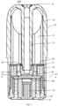
- FIG. 1 to FIG. 6 are respectively a three-dimensional assembly schematic view, a schematic cross-sectional view, and a schematic three-dimensional exploded view of an atomizer 100 according to an embodiment of the present invention.
- the atomizer 100 is configured to atomize a liquid substrate to generate an aerosol, and may include a housing 10, a holder 20, a bottom base 30, a heating member 40, and a capillary element 50.
- the housing 10 may be mounted in cooperation with the bottom base 30 to form an internal space, so that the holder 20, the heating member 40, and the capillary element 50 are mounted and accommodated in the internal space.
- the housing 10 defines a liquid storage cavity 11 for storing the liquid substrate.
- the liquid storage cavity 11 is an accommodating space defined in the housing 10, and is configured to store the liquid substrate and supply the liquid substrate to the capillary element 50.
- the liquid substrate may be, for example, a liquid such as an e-liquid or a chemical solution.
- the liquid substrate may also be referred to as a liquid
- the atomization may also be referred to as vaporization
- the aerosol may also be referred to as smoke, vapor, or atomized vapor.
- the housing 10 may be further provided with a mouthpiece portion 12, and the housing 10 may further have a discharging pipe 13 inside.
- the discharging pipe 13 defines a hollow pipe for an aerosol formed on an atomization surface of the capillary element 50 to pass through and be discharged through the mouthpiece portion 12.
- FIG. 7 and FIG. 8 are two schematic three-dimensional diagrams of a holder 20 of the atomizer 100 shown in FIG. 5 .
- the holder 20 includes a liquid passage 21 and a first surface 22 and is arranged in the housing 10.
- the liquid passage 21 is in fluid communication with the liquid storage cavity 11.
- the first surface 22 faces away from the liquid storage cavity 11.
- the liquid passage 21 ends at the first surface 22.
- the first surface 22 may surround the liquid passage 21.
- the holder 20 may be made of a flexible material such as silicone or a thermoplastic elastomer (TPE), and may be inserted into the housing 10 to form a seal with the housing 10.
- the holder 20 may further include a second surface 26 facing away from the first surface 22.
- the liquid passage 21 extends from the second surface 26 to the first surface 22 through the holder 20.
- the first surface 22 forms a continuous annular surface at a periphery of the liquid passage 21 to surround the liquid passage 21.
- FIG. 9 is a schematic three-dimensional diagram of a bottom base 30 of the atomizer 100 shown in FIG. 5 .
- the bottom base 30 is configured to support a part of the heating member 40 and bring the heating member 40 into contact with the capillary element 50, so that the capillary element 50 is clamped between the first surface 22 and the heating element 40.
- the bottom base 30 may include an accommodating cavity 31 and is connected to the housing 10.
- a block 34 may be provided on a side surface of the bottom base 30 for engagement with a corresponding slot 14 on the housing 10.
- the accommodating cavity 31 may be arranged on a side of the bottom base 30 facing the liquid storage cavity 11.
- the accommodating cavity 31 may be surrounded by a cylindrical wall, or may be surrounded by a plurality of protruding portions 32.
- the capillary element 50 and the heating member 40 are arranged in the accommodating cavity 31.
- FIG. 10 is a schematic three-dimensional diagram of a heating member 40 of the atomizer 100 shown in FIG. 5 .
- the heating member 40 extends substantially flat. Further, the heating member 40 may be arranged in the accommodating cavity 31.
- the heating member 40 may be in a shape of a flat plate as a whole, and a plurality of through holes are provided in a thickness direction, so that the aerosol generated through atomization can be dispersed away through the through holes in a direction away from the capillary element 50.
- the heating member 40 may be made by perforating a sheet material, or may be a heating mesh structure having mesh holes, or may be a circuit structure with winding bends.
- the heating member 40 may be fixedly arranged on the bottom base 30 and located in the accommodating cavity 31.
- the capillary element 50 covers at least a part of the first surface 22 and blocks the liquid passage 21, and is configured to receive and store the liquid substrate from the liquid storage cavity 11 through the liquid passage 21, and convey the liquid substrate to a vicinity of the heating member 40. Further, the capillary element 50 may be arranged in the accommodating cavity 31 and clamped between the first surface 22 and the heating member 40.
- the capillary element 50 may be made of a material having capillary passages or pores, for example, a hard or rigid capillary structure such as a cotton fiber, a porous ceramic body, a glass fiber rope, a porous glass ceramic, or a porous glass.
- the capillary element 50 may be substantially in a shape of a flat plate, to fit the first surface 22 of the holder 20.
- the capillary element 50 fits the first surface 22, thereby covering the liquid passage 21. This enables the liquid substrate stored in the liquid storage cavity 11 to be conveyed to the capillary element 50 through the liquid passage 21 without leaking to a component outside the capillary element 50 through the liquid passage 21.
- the bottom base 30 is used to support the part of the heating member 40 and bring the heating member 40 into contact with the capillary element 50, and then the housing 10 accommodates the holder 20. Therefore, when the bottom base 30 is connected to the housing 10, the capillary element 50 can be clamped between the first surface 22 of the holder 20 and the heating member 40, thereby implementing assembly of the atomizer 100. In this way, the atomizer 100 in this application has a simple structure and is easy to mount.
- the atomizer 100 further includes a supporting member 60.
- the supporting member 60 includes an opening hole 61.
- the supporting member 60 is arranged between the liquid storage cavity 11 and the holder 20, and the opening hole 61 is in fluid communication with the liquid storage cavity 11 and the liquid passage 21.
- the holder 20 is further provided with an air passage 23.
- a ventilation passage 24 is formed between the supporting member 60 and the holder 20, and the air passage 23 and the ventilation passage 24 are in fluid communication with the opening hole 61.
- the ventilation passage 24 may be a small-diameter passage such as a capillary passage. When the liquid substrate is included in the ventilation passage 24, blocking may be achieved through the adsorption between the liquid substrate and the ventilation passage 24.
- the supporting member 60 may further include an insertion hole 62 for allowing an end of the discharging pipe 13 to pass through.
- the air passage 23 may extend from the second surface 26 to the first surface 22 through the holder 20. The air passage 23 may be in communication with the external air through the space in the bottom base 30.
- the ventilation passage 24 may be arranged only on the second surface 26 of the holder 20, or may be arranged only on a side of the supporting member 60 facing the holder 20.
- the ventilation passage 24 may be jointly surrounded by a groove on the holder 20 and a groove on the supporting member 60.
- the supporting member 60 may be made of a hard material, and the supporting member 60 may be in a sealed fit with the second surface 26 of the holder 20.
- the supporting member 60 is in a shape of a flat plate
- the ventilation passage 24 is arranged on the holder 20
- the ventilation passage 24 extends from the air passage 23 to the liquid passage 21.
- the ventilation passage 24 may be integrally formed when the holder 20 is formed.
- the flat plate-shaped supporting member 60 fits the holder 20, so that an opening above the ventilation passage 24 can be closed, and the ventilation passage 24 is in communication with the air passage 23 and the liquid passage 21 only at two ends.
- a liquid guide groove 25 is further provided on the first surface 22.
- the liquid guide groove 25 extends from the liquid passage 21 to a central region corresponding to the capillary element 50. Since the capillary element 50 fits the first surface 22 and covers the liquid passage 21, the liquid substrate stored in the liquid storage cavity 11 can be directly conveyed to a part of the capillary element 50 exactly opposite to the liquid passage 21 through the liquid passage 21.
- the liquid guide groove 25 is provided, so that the liquid substrate can be directly conveyed to the central region of the capillary element 50 through the liquid passage 21 and the liquid guide groove 25, thereby ensuring that the liquid substrate is quickly supplied to a central region requiring a large amount of atomization.
- the holder 20 may include a flange portion 20A.
- the flange portion 20A extends from the first surface 22 away from the second surface 26, and may circumferentially surround an upper half 37 of the bottom base 30, to form a seal between the upper half 37 and the housing 10.
- the number of liquid passages 21 is two, and the liquid guide groove 25 is in communication with the two liquid passages 21.
- the liquid guide groove 25 may extend from one of the liquid passages 21 to the central region corresponding to the capillary element 50, and further extend to the other liquid passage 21. Since a cross section of the holder 20 may usually be rectangular or elliptical, two liquid passages 21 may be arranged on the holder 20 in a lateral direction in which the holder 20 has a longer dimension, to supply the liquid substrate to the capillary element 50 in a roughly even manner.
- one liquid guide groove 25 may be used to be in communication with the two liquid passages 21, so that both the two liquid passages 21 can supply the liquid substrate toward the central region of the capillary element 50.
- a side of the liquid guide groove 25 facing the capillary element 50 is open, and a cross-sectional area of the liquid guide groove 25 may be approximately constant, or may gradually decrease as the liquid guide groove approaches the central region of the capillary element 50.
- the number of air passages 23 and the number of ventilation passages 24 may both be two. Each ventilation passage 24 is in communication with one air passage 23 and one liquid passage 21.
- At least a part of the first surface 22 around the liquid passage 21 is an arc surface protruding toward the capillary element 50.
- a cross section of the arc surface may be in a curved shape such as an arc or a circular arc.
- This embodiment is applicable to the capillary element 50 using a liquid guide cotton. Specifically, due to the deformability of the liquid guide cotton, the design of this arc surface can strengthen the compression and sealing of the liquid guide cotton at the liquid passage 21, to prevent a gap from being formed between the capillary element 50 in the form of the liquid guide cotton and the first surface 22, thereby preventing the liquid substrate from leaking through the gap.
- the first surface 22 is entirely located in an arc surface Al, and a central axis A2 of the arc surface A1 is parallel to a length direction A3 of the capillary element 50. In this way, the design and manufacture of the first surface 22 can be facilitated. In addition, the liquid guide cotton can be compressed and sealed at the liquid passage 21.
- the liquid guide groove 25 may be provided on a baffle plate 27, and the holder 20 may further include an insertion opening 28.
- the insertion opening 28 is opposite to the baffle plate 27, and an airflow space 29 exists between the insertion opening 27 and the baffle plate 27.
- An end of the discharging pipe 13 of the housing 10 may be inserted into the insertion opening 28.
- the holder 20 may further include a side wall opening 20B for a gas to carry an aerosol generated on an atomization surface of the capillary element 50 to bypass the capillary element 50 and enter the airflow space 29.
- the atomizer 100 further includes an electrode 70.
- the electrode 70 is inserted into the bottom base 30 and is connected to the heating member 40.
- conductive connection may be implemented through soldering, insertion, or abutment.
- the electrode 70 may be inserted into the bottom base 30 in a tight fit, and one end of the electrode 70 is exposed outward from the bottom base 30, to be connected to a battery in a power supply assembly.
- another end of the electrode 70 may be connected to a connection end 41 of the heating member 40 through, for example, spot soldering.
- An insertion hole 47 may be provided at the connection end 41 of the heating member 40.
- the electrode 70 may be fixed in the bottom base 30 first, the insertion hole 47 of the heating member 40 is sleeved over the other end of the electrode 70, and then the other end of the electrode 70 is connected to the insertion hole 47 through spot soldering. In this way, both the electrode 70 and the heating member 40 can be fixedly arranged on the bottom base 30.
- the bottom base 30 includes a plurality of protruding portions 32 extending toward the liquid storage cavity 11.
- the plurality of protruding portions 32 surround the accommodating cavity 31 and clamp the capillary element 50 in the accommodating cavity 31.
- the capillary element 50 is clamped in the accommodating cavity 31 by using the protruding portions 32, to facilitate further assembly and connection of the bottom base 30 with the housing 10.
- the heating member 40 includes two connection ends 41 and a heating portion 42 bent and extending between the two connection ends 41.
- the heating portion 42 may include repetitive circuits of an S-shape, a Z-shape, a U-shape, or the like. These repetitive circuits may be arranged in series.
- a first reinforcing portion 43 is further connected to the heating portion 42, and the width of the first reinforcing portion 43 is greater than the width of the heating portion 42.
- the first reinforcing portion 43 may not be located in a current path, and therefore, the first reinforcing portion 43 may not generate heat. In this way, since the width of the first reinforcing portion 43 is greater than the width of the heating portion 42, the first reinforcing portion 43 may have higher structural strength than that of the heating portion 42, and the first reinforcing portion 43 can support the heating portion 42, so that the heating member 40 as a whole has higher strength.
- the first reinforcing portion 43 may be supported on the bottom base 30, so that the heating member 40 has sufficient strength to be pressed into the capillary element 50 in the form of the liquid guide cotton, to reduce a thickness of an e-liquid film on the atomization surface of the capillary element 50, thereby reducing an e-liquid splashing phenomenon during use of the atomizer 100.
- a cross-sectional shape of the first reinforcing portion 43 is curved.
- the first reinforcing portion 43 connected to a middle part of the heating portion 42 may be designed to have a bent structure, to increase strength.
- a cross section of the bent structure may be of a V-shape, a U-shape, a circular arc, or the like, which has higher strength than a structure with a one-line cross section.
- the atomizer 100 in the embodiments of this application does not need to be separately provided with a component for supporting the heating member 40, so that assembly of the atomizer 100 can be simplified.
- the heating member 40 further includes a second reinforcing portion 44.
- the second reinforcing portion 44 is connected to the connection end 41 and the heating portion 42.
- the second reinforcing portion 44 is arranged in parallel with the first reinforcing portion 43. Through arrangement of the second reinforcing portion 44, the heating member 40 as a whole can further have higher strength.
- a cross-sectional shape of the second reinforcing portion 44 is curved.
- the second reinforcing portion 44 is designed to have a bent structure, to increase strength. Similar to the bent structure of the first reinforcing portion 43, a cross section of the bent structure of the second reinforcing portion 44 may be of a V-shape, a U-shape, a circular arc, or the like, which has higher strength than a structure with a one-line cross section.
- the bottom base 30 includes a supporting beam 33.
- the supporting beam 33 is configured to support the first reinforcing portion 43 and avoid the heating portion 42.
- the first reinforcing portion 43 may be supported on the supporting beam 33 of the bottom base 30, so that the heating member 40 has sufficient strength to be pressed into the capillary element 50 in the form of the liquid guide cotton.
- the supporting beam 33 may be an end surface of a supporting wall 35 in the bottom base 30 facing the heating member 40.
- the bottom base 30 may include an air inlet tube 36. One end of the air inlet tube 36 is in communication with the external air, and the other end may be exactly opposite to the heating portion 42 of the heating member 40.
- the supporting beam 33 includes a first supporting beam 331 and a second supporting beam 332 that are spaced apart from each other.
- An air inlet region 38 is formed between the first supporting beam 331 and the second supporting beam 332.
- the air inlet tube 36 is arranged in the air inlet region 38, and an end of the air inlet tube 36 may have a preset distance from the heating member 40. Therefore, the air inputted through the air inlet tube 36 may slightly dispersed in the air inlet region 38, so that the air can be blown onto at least most of a heating region of the heating member 40.
- the heating portion 42 is arranged between the first supporting beam 331 and the second supporting beam 332 through the first reinforcing portion 43. In this way, the heating portion 42 can be stably supported, so that the heating portion 42 is in full contact with the capillary element 50.
- the heating portion 42 includes a parallel circuit structure 45 in a part corresponding to the central region of the capillary element 50.
- the parallel circuit structure 45 may be a closed ring, such as an O-shape, a square shape, or a racetrack shape.
- the first reinforcing portion 43 may extend from the parallel circuit structure 45 toward the connection end 41; and the first reinforcing portion 43 may be arranged in parallel with the second reinforcing portion 44.
- FIG. 11 is a schematic three-dimensional diagram of a heating member 40 according to another embodiment of the present invention.
- the heating member 40 in this embodiment is substantially the same as the heating member 40 shown in FIG. 10 , and may also include a connection end 41, a curved heating portion 42, a first reinforcing portion 43, and a second reinforcing portion 44.
- a difference between the two is that, in the heating member 40 in the embodiment shown in FIG. 11 , the heating portion 42 includes a widened circuit structure 46 in a part corresponding to the central region of the capillary element 50. The width of the widened circuit structure 46 is greater than the width of another part of the heating portion 42.
- the first reinforcing portion 43 may extend from the widened circuit structure 46 in the same direction, and the first reinforcing portion 43 may have the same width with the widened circuit structure 46.
- the widened circuit structure 46 Through arrangement of the widened circuit structure 46, an amount of heat generated in a region in which the widened circuit structure 46 is located is reduced, so that heat in a central region of the heating portion 42 can be effectively reduced, thereby regulating local overheating.
- the first reinforcing portion 43 may extend from the widened circuit structure 46 toward the connection end 41.
- the atomizer 100 may form an electronic atomization device with the power supply assembly.
- a power switch of the power supply assembly may be turned on first, so that the battery can supply power to the heating member 40 of the atomizer 100.
- a controller in the electronic atomization device may start the power supply assembly and the atomizer 100 to work based on an inhalation action, to finally generate an aerosol for the user to inhale.
- the liquid substrate from the liquid storage cavity 11 is heated and atomized by the heating member 40 to form vapor.
- the external air may flow through the air inlet tube 36 to be conveyed to an atomization surface of the capillary element 50 that is in contact with the heating member 40. Then, the formed aerosol is carried to the airflow space 29 by bypassing the capillary element 50, so that the formed aerosol is discharged through the discharging pipe 13.
Landscapes
- Disinfection, Sterilisation Or Deodorisation Of Air (AREA)
- Nozzles (AREA)
Abstract
Description
- This application claims priority to
Chinese Patent Application No. 202210043243.8, entitled "ATOMIZER AND HEATING MEMBER THEREOF" and filed with the China National Intellectual Property Administration on January 14, 2022 - The present invention relates to the field of electronic atomization technologies, and in particular, to an atomizer and a heating member thereof.
- An electronic atomization device is an electronic product that heats and atomizes a liquid substrate such as an e-liquid and a chemical solution into an aerosol for inhalation and use.
- The electronic atomization device may include an atomizer and a power supply assembly, and the power supply assembly is configured to supply power to the atomizer. The atomizer may include an atomization core assembly and an atomization chamber. The atomization core assembly is configured to generate heat when being powered on, to atomize the liquid substrate. The atomization chamber is configured to supply a liquid substrate to be heated and atomized to the atomization core assembly.
- In the atomizer, a porous ceramic body, a liquid guide cotton, or the like is usually used as a capillary liquid guide element for absorbing the liquid substrate, and a heating element is arranged in contact with an atomization surface of the capillary liquid guide element to heat at least a part of the liquid substrate in the capillary liquid guide element, to generate an aerosol.
- In a related atomizer structure, mounting structures and mounting manners of the heating element and the capillary liquid guide element are complex.
- The present invention aims to provide an atomizer and a heating member thereof, to resolve a technical problem that a current atomizer has a complex structure.
- The present invention uses the following technical solutions to resolve the technical problem. An atomizer is provided, which is configured to atomize a liquid substrate to generate an aerosol. The atomizer includes: a housing, where the housing defines a liquid storage cavity for storing the liquid substrate; a holder, where the holder is arranged in the housing and includes a liquid passage and a first surface, the liquid passage is in fluid communication with the liquid storage cavity, the first surface faces away from the liquid storage cavity, and the liquid passage ends at the first surface; a heating member, where the heating member extends substantially flat; a capillary element, where the capillary element covers on at least a part of the first surface and blocks the liquid passage, and is configured to receive and store the liquid substrate from the liquid storage cavity through the liquid passage, and convey the liquid substrate to a vicinity of the heating member; and a bottom base, configured to support a part of the heating member and bring the heating element into contact with the capillary element, so that the capillary element is clamped between the first surface and the heating member .
- In a preferred implementation, the bottom base includes an accommodating cavity, and the capillary element and the heating member are arranged in the accommodating cavity.
- In a preferred implementation, the atomizer further includes a supporting member, and the supporting member includes an opening hole, where the supporting member is arranged between the liquid storage cavity and the holder, the opening hole is in fluid communication with the liquid storage cavity and the liquid passage; and the holder is further provided with an air passage, a ventilation passage is formed between the supporting member and the holder, and the air passage and the ventilation passage are in fluid communication with the opening hole.
- In a preferred implementation, the supporting member is in a shape of a flat plate, the ventilation passage is arranged on the holder, and the ventilation passage extends from the air passage to the liquid passage.
- In a preferred implementation, a liquid guide groove is further provided on the first surface, and the liquid guide groove extends from the liquid passage to a central region corresponding to the capillary element.
- In a preferred implementation, the number of liquid passages is two, and the liquid guide groove is in communication with the two liquid passages.
- In a preferred implementation, at least a part of the first surface around the liquid passage is an arc surface protruding toward the capillary element.
- In a preferred implementation, the first surface is entirely located in an arc surface, and a central axis of the arc surface is parallel to a length direction of the capillary element.
- In a preferred implementation, the atomizer further includes an electrode, and the electrode is inserted into the bottom base and is connected to the heating member.
- In a preferred implementation, the bottom base includes a plurality of protruding portions extending toward the liquid storage cavity, and the plurality of protruding portions surround the accommodating cavity and clamp the capillary element in the accommodating cavity.
- In a preferred implementation, the heating member includes two connection ends and a heating portion bent and extending between the two connection ends, a first reinforcing portion is further connected to the heating portion, and the width of the first reinforcing portion is greater than the width of the heating portion.
- In a preferred implementation, a cross-sectional shape of the first reinforcing portion is curved.
- In a preferred implementation, the heating member further includes a second reinforcing portion, the second reinforcing portion is connected to the connection end and the heating portion, and the second reinforcing portion is arranged in parallel with the first reinforcing portion.
- In a preferred implementation, a cross-sectional shape of the second reinforcing portion is curved.
- In a preferred implementation, the bottom base includes a supporting beam, and the supporting beam supports the first reinforcing portion and avoids the heating portion.
- In a preferred implementation, the heating portion includes a parallel circuit structure in a part corresponding to the central region of the capillary element; or the heating portion includes a widened circuit structure in a part corresponding to the central region of the capillary element, and the width of the widened circuit structure is greater than the width of another part of the heating portion.
- The present invention further uses the following technical solutions to resolve the technical problem. An atomizer is provided, which is configured to atomize a liquid substrate to generate an aerosol. The atomizer includes: a housing, where the housing defines a liquid storage cavity for storing the liquid substrate; a heating member, extending substantially flat; a capillary element, where the capillary element is configured to receive a liquid substrate from the liquid storage cavity and convey the liquid substrate to a vicinity of the heating member; and a bottom base, configured to support a part of the heating member and bring the heating member into contact with the capillary element, where the heating member includes two connection ends, a heating portion bent and extending between the two connection ends, and a first reinforcing portion extending from the heating portion, the width of the first reinforcing portion is greater than the width of the heating portion; and the bottom base includes a supporting beam, and the supporting beam supports the first reinforcing portion and avoids the heating portion.
- In a preferred implementation, the supporting beam includes a first supporting beam and a second supporting beam that are spaced apart from each other, and an air inlet region is formed between the first supporting beam and the second supporting beam.
- In a preferred implementation, the heating portion is arranged between the first supporting beam and the second supporting beam through the first reinforcing portion.
- In a preferred implementation, the heating member further includes two second reinforcing portions correspondingly connected to the two connection ends, the two second reinforcing portions extend substantially in parallel with each other, and the heating portion is bent and extends between the two second reinforcing portions.
- The present invention further uses the following technical solutions to resolve the technical problem. A heating member for an atomizer is provided, where the heating member extends substantially flat and comprises two connection ends, a heating portion bent and extending between the two connection ends, and a first reinforcing portion extending from the heating portion, where the width of the first reinforcing portion is greater than the width of the heating portion.
- The present invention has the following beneficial effects: In the atomizer in this embodiment, the bottom base is used to support the part of the heating member and bring the heating member into contact with the capillary element, and then the housing accommodates the holder. In this way, when the bottom base is connected to the housing, the capillary element can be clamped between the first surface of the holder and the heating member, thereby implementing assembly of the atomizer. In this way, the atomizer in this application has a simple structure and is easy to mount. Further, the first reinforcing portion is arranged, to support the heating portion, so that the heating member as a whole has higher strength.
- One or more embodiments are described by way of example with reference to the corresponding accompanying drawings, and the exemplary descriptions are not to be construed as limiting the embodiments. Elements in the accompanying drawings that have same reference numerals represent similar elements, and unless otherwise particularly stated, the figures in the accompanying drawings are not drawn to scale.
-
FIG. 1 is a three-dimensional assembly schematic view of an atomizer according to an embodiment of the present invention; -
FIG. 2 is another three-dimensional assembly schematic view of the atomizer shown inFIG. 1 ; -
FIG. 3 is a schematic cross-sectional view of the atomizer shown inFIG. 1 ; -
FIG. 4 is another schematic cross-sectional view of the atomizer shown inFIG. 1 ; -
FIG. 5 is a schematic three-dimensional exploded view of the atomizer shown inFIG. 1 ; -
FIG. 6 is another schematic three-dimensional exploded view of the atomizer shown inFIG. 1 ; -
FIG. 7 is a schematic three-dimensional diagram of a holder of the atomizer shown inFIG. 5 ; -
FIG. 8 is another schematic three-dimensional diagram of the holder shown inFIG. 7 ; -
FIG. 9 is a schematic three-dimensional diagram of a bottom base of the atomizer shown inFIG. 5 ; -
FIG. 10 is a schematic three-dimensional diagram of a heating member of the atomizer shown inFIG. 5 ; and -
FIG. 11 is a schematic three-dimensional diagram of a heating member according to another embodiment of the present invention. - For ease of understanding of the present invention, the present invention is described below in more detail with reference to accompanying drawings and specific implementations. It should be noted that, when an element is expressed as "being fixed to" another element, the element may be directly on the another element, or one or more intermediate elements may exist between the element and the another element. When an element is expressed as "being connected to" another element, the element may be directly connected to the another element, or one or more intermediate elements may exist between the element and the another element. The terms "vertical", "horizontal", "left", "right", "inside", "outside", and similar expressions used in this specification are merely used for an illustrative purpose.
- Unless otherwise defined, meanings of all technical and scientific terms used in this specification are the same as meanings generally understood by a person skilled in the technical field to which the present invention belongs. The terms used in this specification of the present invention are merely intended to describe objectives of the specific embodiments, but are not intended to limit the present invention. The term "and/or" used in this specification includes any or all combinations of one or more related listed items.
- In addition, technical features involved in different embodiments of the present invention described below may be combined together if there is no conflict between each other.
- With reference to
FIG. 1 to FIG. 6, FIG. 1 to FIG. 6 are respectively a three-dimensional assembly schematic view, a schematic cross-sectional view, and a schematic three-dimensional exploded view of anatomizer 100 according to an embodiment of the present invention. Theatomizer 100 is configured to atomize a liquid substrate to generate an aerosol, and may include ahousing 10, aholder 20, abottom base 30, aheating member 40, and acapillary element 50. Thehousing 10 may be mounted in cooperation with thebottom base 30 to form an internal space, so that theholder 20, theheating member 40, and thecapillary element 50 are mounted and accommodated in the internal space. - The
housing 10 defines aliquid storage cavity 11 for storing the liquid substrate. Theliquid storage cavity 11 is an accommodating space defined in thehousing 10, and is configured to store the liquid substrate and supply the liquid substrate to thecapillary element 50. The liquid substrate may be, for example, a liquid such as an e-liquid or a chemical solution. In this specification, the liquid substrate may also be referred to as a liquid, the atomization may also be referred to as vaporization, and the aerosol may also be referred to as smoke, vapor, or atomized vapor. Thehousing 10 may be further provided with amouthpiece portion 12, and thehousing 10 may further have a dischargingpipe 13 inside. The dischargingpipe 13 defines a hollow pipe for an aerosol formed on an atomization surface of thecapillary element 50 to pass through and be discharged through themouthpiece portion 12. - With reference to
FIG. 7 and FIG. 8, FIG. 7 and FIG. 8 are two schematic three-dimensional diagrams of aholder 20 of theatomizer 100 shown inFIG. 5 . Theholder 20 includes aliquid passage 21 and afirst surface 22 and is arranged in thehousing 10. Theliquid passage 21 is in fluid communication with theliquid storage cavity 11. Thefirst surface 22 faces away from theliquid storage cavity 11. Theliquid passage 21 ends at thefirst surface 22. Thefirst surface 22 may surround theliquid passage 21. Theholder 20 may be made of a flexible material such as silicone or a thermoplastic elastomer (TPE), and may be inserted into thehousing 10 to form a seal with thehousing 10. Theholder 20 may further include asecond surface 26 facing away from thefirst surface 22. Theliquid passage 21 extends from thesecond surface 26 to thefirst surface 22 through theholder 20. Thefirst surface 22 forms a continuous annular surface at a periphery of theliquid passage 21 to surround theliquid passage 21. - With reference to
FIG. 9, FIG. 9 is a schematic three-dimensional diagram of abottom base 30 of theatomizer 100 shown inFIG. 5 . Thebottom base 30 is configured to support a part of theheating member 40 and bring theheating member 40 into contact with thecapillary element 50, so that thecapillary element 50 is clamped between thefirst surface 22 and theheating element 40. Further, thebottom base 30 may include anaccommodating cavity 31 and is connected to thehousing 10. For example, ablock 34 may be provided on a side surface of thebottom base 30 for engagement with acorresponding slot 14 on thehousing 10. Theaccommodating cavity 31 may be arranged on a side of thebottom base 30 facing theliquid storage cavity 11. Theaccommodating cavity 31 may be surrounded by a cylindrical wall, or may be surrounded by a plurality of protrudingportions 32. Thecapillary element 50 and theheating member 40 are arranged in theaccommodating cavity 31. - With reference to
FIG. 10, FIG. 10 is a schematic three-dimensional diagram of aheating member 40 of theatomizer 100 shown inFIG. 5 . Theheating member 40 extends substantially flat. Further, theheating member 40 may be arranged in theaccommodating cavity 31. For example, theheating member 40 may be in a shape of a flat plate as a whole, and a plurality of through holes are provided in a thickness direction, so that the aerosol generated through atomization can be dispersed away through the through holes in a direction away from thecapillary element 50. Theheating member 40 may be made by perforating a sheet material, or may be a heating mesh structure having mesh holes, or may be a circuit structure with winding bends. Theheating member 40 may be fixedly arranged on thebottom base 30 and located in theaccommodating cavity 31. - The
capillary element 50 covers at least a part of thefirst surface 22 and blocks theliquid passage 21, and is configured to receive and store the liquid substrate from theliquid storage cavity 11 through theliquid passage 21, and convey the liquid substrate to a vicinity of theheating member 40. Further, thecapillary element 50 may be arranged in theaccommodating cavity 31 and clamped between thefirst surface 22 and theheating member 40. Thecapillary element 50 may be made of a material having capillary passages or pores, for example, a hard or rigid capillary structure such as a cotton fiber, a porous ceramic body, a glass fiber rope, a porous glass ceramic, or a porous glass. Thecapillary element 50 may be substantially in a shape of a flat plate, to fit thefirst surface 22 of theholder 20. Thecapillary element 50 fits thefirst surface 22, thereby covering theliquid passage 21. This enables the liquid substrate stored in theliquid storage cavity 11 to be conveyed to thecapillary element 50 through theliquid passage 21 without leaking to a component outside thecapillary element 50 through theliquid passage 21. - In the
atomizer 100 in this embodiment, thebottom base 30 is used to support the part of theheating member 40 and bring theheating member 40 into contact with thecapillary element 50, and then thehousing 10 accommodates theholder 20. Therefore, when thebottom base 30 is connected to thehousing 10, thecapillary element 50 can be clamped between thefirst surface 22 of theholder 20 and theheating member 40, thereby implementing assembly of theatomizer 100. In this way, theatomizer 100 in this application has a simple structure and is easy to mount. - In an optional embodiment, with reference to
FIG. 3 to FIG. 8 , theatomizer 100 further includes a supportingmember 60. The supportingmember 60 includes anopening hole 61. The supportingmember 60 is arranged between theliquid storage cavity 11 and theholder 20, and theopening hole 61 is in fluid communication with theliquid storage cavity 11 and theliquid passage 21. Theholder 20 is further provided with anair passage 23. Aventilation passage 24 is formed between the supportingmember 60 and theholder 20, and theair passage 23 and theventilation passage 24 are in fluid communication with theopening hole 61. Theventilation passage 24 may be a small-diameter passage such as a capillary passage. When the liquid substrate is included in theventilation passage 24, blocking may be achieved through the adsorption between the liquid substrate and theventilation passage 24. Only when a pressure in theliquid storage cavity 11 is lower than a specific level, a pressure difference between external air and theliquid storage cavity 11 may cause the external air to flow into theliquid storage cavity 11 through theventilation passage 24. Further, the supportingmember 60 may further include aninsertion hole 62 for allowing an end of the dischargingpipe 13 to pass through. Theair passage 23 may extend from thesecond surface 26 to thefirst surface 22 through theholder 20. Theair passage 23 may be in communication with the external air through the space in thebottom base 30. In this way, when the pressure in theliquid storage cavity 11 decreases, the external air can be conveyed to theliquid storage cavity 11 through thebottom base 30, theair passage 23, theventilation passage 24, and theopening hole 61, so that the pressure in theliquid storage cavity 11 is approximately balanced with that of the outside, and the liquid substrate can be smoothly supplied to thecapillary element 50. In some embodiments, theventilation passage 24 may be arranged only on thesecond surface 26 of theholder 20, or may be arranged only on a side of the supportingmember 60 facing theholder 20. Alternatively, theventilation passage 24 may be jointly surrounded by a groove on theholder 20 and a groove on the supportingmember 60. The supportingmember 60 may be made of a hard material, and the supportingmember 60 may be in a sealed fit with thesecond surface 26 of theholder 20. - In an optional embodiment, with reference to
FIG. 3 to FIG. 8 , the supportingmember 60 is in a shape of a flat plate, theventilation passage 24 is arranged on theholder 20, and theventilation passage 24 extends from theair passage 23 to theliquid passage 21. In this way, theventilation passage 24 may be integrally formed when theholder 20 is formed. In addition, the flat plate-shaped supportingmember 60 fits theholder 20, so that an opening above theventilation passage 24 can be closed, and theventilation passage 24 is in communication with theair passage 23 and theliquid passage 21 only at two ends. - In an optional embodiment, with reference to
FIG. 3 to FIG. 8 , aliquid guide groove 25 is further provided on thefirst surface 22. Theliquid guide groove 25 extends from theliquid passage 21 to a central region corresponding to thecapillary element 50. Since thecapillary element 50 fits thefirst surface 22 and covers theliquid passage 21, the liquid substrate stored in theliquid storage cavity 11 can be directly conveyed to a part of thecapillary element 50 exactly opposite to theliquid passage 21 through theliquid passage 21. In this embodiment, theliquid guide groove 25 is provided, so that the liquid substrate can be directly conveyed to the central region of thecapillary element 50 through theliquid passage 21 and theliquid guide groove 25, thereby ensuring that the liquid substrate is quickly supplied to a central region requiring a large amount of atomization. Further, theholder 20 may include aflange portion 20A. Theflange portion 20A extends from thefirst surface 22 away from thesecond surface 26, and may circumferentially surround anupper half 37 of thebottom base 30, to form a seal between theupper half 37 and thehousing 10. - In an optional embodiment, with reference to
FIG. 3 to FIG. 8 , the number ofliquid passages 21 is two, and theliquid guide groove 25 is in communication with the twoliquid passages 21. For example, theliquid guide groove 25 may extend from one of theliquid passages 21 to the central region corresponding to thecapillary element 50, and further extend to theother liquid passage 21. Since a cross section of theholder 20 may usually be rectangular or elliptical, twoliquid passages 21 may be arranged on theholder 20 in a lateral direction in which theholder 20 has a longer dimension, to supply the liquid substrate to thecapillary element 50 in a roughly even manner. Further, oneliquid guide groove 25 may be used to be in communication with the twoliquid passages 21, so that both the twoliquid passages 21 can supply the liquid substrate toward the central region of thecapillary element 50. A side of theliquid guide groove 25 facing thecapillary element 50 is open, and a cross-sectional area of theliquid guide groove 25 may be approximately constant, or may gradually decrease as the liquid guide groove approaches the central region of thecapillary element 50. Further, the number ofair passages 23 and the number ofventilation passages 24 may both be two. Eachventilation passage 24 is in communication with oneair passage 23 and oneliquid passage 21. - In an optional embodiment, with reference to
FIG. 4 andFIG. 8 , at least a part of thefirst surface 22 around theliquid passage 21 is an arc surface protruding toward thecapillary element 50. A cross section of the arc surface may be in a curved shape such as an arc or a circular arc. This embodiment is applicable to thecapillary element 50 using a liquid guide cotton. Specifically, due to the deformability of the liquid guide cotton, the design of this arc surface can strengthen the compression and sealing of the liquid guide cotton at theliquid passage 21, to prevent a gap from being formed between thecapillary element 50 in the form of the liquid guide cotton and thefirst surface 22, thereby preventing the liquid substrate from leaking through the gap. - In an optional embodiment, with reference to
FIG. 3 to FIG. 8 , thefirst surface 22 is entirely located in an arc surface Al, and a central axis A2 of the arc surface A1 is parallel to a length direction A3 of thecapillary element 50. In this way, the design and manufacture of thefirst surface 22 can be facilitated. In addition, the liquid guide cotton can be compressed and sealed at theliquid passage 21. - Further, with reference to
FIG. 7 and FIG. 8 , theliquid guide groove 25 may be provided on abaffle plate 27, and theholder 20 may further include aninsertion opening 28. Theinsertion opening 28 is opposite to thebaffle plate 27, and anairflow space 29 exists between theinsertion opening 27 and thebaffle plate 27. An end of the dischargingpipe 13 of thehousing 10 may be inserted into theinsertion opening 28. Theholder 20 may further include a side wall opening 20B for a gas to carry an aerosol generated on an atomization surface of thecapillary element 50 to bypass thecapillary element 50 and enter theairflow space 29. - In an optional embodiment, with reference to
FIG. 2 to FIG. 8 , theatomizer 100 further includes anelectrode 70. Theelectrode 70 is inserted into thebottom base 30 and is connected to theheating member 40. For example, conductive connection may be implemented through soldering, insertion, or abutment. Theelectrode 70 may be inserted into thebottom base 30 in a tight fit, and one end of theelectrode 70 is exposed outward from thebottom base 30, to be connected to a battery in a power supply assembly. In some embodiments, with reference toFIG. 10 , another end of theelectrode 70 may be connected to aconnection end 41 of theheating member 40 through, for example, spot soldering. Aninsertion hole 47 may be provided at the connection end 41 of theheating member 40. During assembly and connection with theelectrode 70, theelectrode 70 may be fixed in thebottom base 30 first, theinsertion hole 47 of theheating member 40 is sleeved over the other end of theelectrode 70, and then the other end of theelectrode 70 is connected to theinsertion hole 47 through spot soldering. In this way, both theelectrode 70 and theheating member 40 can be fixedly arranged on thebottom base 30. - In an optional embodiment, with reference to
FIG. 5 andFIG. 9 , thebottom base 30 includes a plurality of protrudingportions 32 extending toward theliquid storage cavity 11. The plurality of protrudingportions 32 surround theaccommodating cavity 31 and clamp thecapillary element 50 in theaccommodating cavity 31. Thecapillary element 50 is clamped in theaccommodating cavity 31 by using the protrudingportions 32, to facilitate further assembly and connection of thebottom base 30 with thehousing 10. - In an optional embodiment, with reference to
FIG. 5 andFIG. 10 , theheating member 40 includes two connection ends 41 and aheating portion 42 bent and extending between the two connection ends 41. For example, theheating portion 42 may include repetitive circuits of an S-shape, a Z-shape, a U-shape, or the like. These repetitive circuits may be arranged in series. A first reinforcingportion 43 is further connected to theheating portion 42, and the width of the first reinforcingportion 43 is greater than the width of theheating portion 42. For example, there may be a plurality of first reinforcingportions 43, and the first reinforcingportion 43 may extend from theheating portion 42 in a direction parallel to the length direction A3 of thecapillary element 50. The first reinforcingportion 43 may not be located in a current path, and therefore, the first reinforcingportion 43 may not generate heat. In this way, since the width of the first reinforcingportion 43 is greater than the width of theheating portion 42, the first reinforcingportion 43 may have higher structural strength than that of theheating portion 42, and the first reinforcingportion 43 can support theheating portion 42, so that theheating member 40 as a whole has higher strength. For example, in an assembly structure, the first reinforcingportion 43 may be supported on thebottom base 30, so that theheating member 40 has sufficient strength to be pressed into thecapillary element 50 in the form of the liquid guide cotton, to reduce a thickness of an e-liquid film on the atomization surface of thecapillary element 50, thereby reducing an e-liquid splashing phenomenon during use of theatomizer 100. - In an optional embodiment, with reference to
FIG. 10 , a cross-sectional shape of the first reinforcingportion 43 is curved. For example, the first reinforcingportion 43 connected to a middle part of theheating portion 42 may be designed to have a bent structure, to increase strength. A cross section of the bent structure may be of a V-shape, a U-shape, a circular arc, or the like, which has higher strength than a structure with a one-line cross section. Correspondingly, theatomizer 100 in the embodiments of this application does not need to be separately provided with a component for supporting theheating member 40, so that assembly of theatomizer 100 can be simplified. - In an optional embodiment, with reference to
FIG. 10 , theheating member 40 further includes a second reinforcingportion 44. The second reinforcingportion 44 is connected to theconnection end 41 and theheating portion 42. The second reinforcingportion 44 is arranged in parallel with the first reinforcingportion 43. Through arrangement of the second reinforcingportion 44, theheating member 40 as a whole can further have higher strength. - In an optional embodiment, with reference to
FIG. 10 , a cross-sectional shape of the second reinforcingportion 44 is curved. The second reinforcingportion 44 is designed to have a bent structure, to increase strength. Similar to the bent structure of the first reinforcingportion 43, a cross section of the bent structure of the second reinforcingportion 44 may be of a V-shape, a U-shape, a circular arc, or the like, which has higher strength than a structure with a one-line cross section. - In an optional embodiment, with reference to
FIG. 5 andFIG. 9 , thebottom base 30 includes a supportingbeam 33. The supportingbeam 33 is configured to support the first reinforcingportion 43 and avoid theheating portion 42. For example, in the assembly structure, the first reinforcingportion 43 may be supported on the supportingbeam 33 of thebottom base 30, so that theheating member 40 has sufficient strength to be pressed into thecapillary element 50 in the form of the liquid guide cotton. The supportingbeam 33 may be an end surface of a supportingwall 35 in thebottom base 30 facing theheating member 40. Further, thebottom base 30 may include anair inlet tube 36. One end of theair inlet tube 36 is in communication with the external air, and the other end may be exactly opposite to theheating portion 42 of theheating member 40. - In an optional embodiment, with reference to
FIG. 5 andFIG. 9 , the supportingbeam 33 includes a first supportingbeam 331 and a second supportingbeam 332 that are spaced apart from each other. Anair inlet region 38 is formed between the first supportingbeam 331 and the second supportingbeam 332. Theair inlet tube 36 is arranged in theair inlet region 38, and an end of theair inlet tube 36 may have a preset distance from theheating member 40. Therefore, the air inputted through theair inlet tube 36 may slightly dispersed in theair inlet region 38, so that the air can be blown onto at least most of a heating region of theheating member 40. - In an optional embodiment, with reference to
FIG. 5 ,FIG. 9, and FIG. 10 , theheating portion 42 is arranged between the first supportingbeam 331 and the second supportingbeam 332 through the first reinforcingportion 43. In this way, theheating portion 42 can be stably supported, so that theheating portion 42 is in full contact with thecapillary element 50. - In an optional embodiment, with reference to
FIG. 5 andFIG. 10 , theheating portion 42 includes aparallel circuit structure 45 in a part corresponding to the central region of thecapillary element 50. For example, theparallel circuit structure 45 may be a closed ring, such as an O-shape, a square shape, or a racetrack shape. Further, the first reinforcingportion 43 may extend from theparallel circuit structure 45 toward theconnection end 41; and the first reinforcingportion 43 may be arranged in parallel with the second reinforcingportion 44. Through arrangement of theparallel circuit structure 45, an amount of heat generated in a region in which theparallel circuit structure 45 is located is reduced, so that heat in a central region of theheating portion 42 can be effectively reduced, thereby regulating local overheating. - In another optional embodiment, with reference to
FIG. 5 andFIG. 11, FIG. 11 is a schematic three-dimensional diagram of aheating member 40 according to another embodiment of the present invention. Theheating member 40 in this embodiment is substantially the same as theheating member 40 shown inFIG. 10 , and may also include aconnection end 41, acurved heating portion 42, a first reinforcingportion 43, and a second reinforcingportion 44. A difference between the two is that, in theheating member 40 in the embodiment shown inFIG. 11 , theheating portion 42 includes a widenedcircuit structure 46 in a part corresponding to the central region of thecapillary element 50. The width of the widenedcircuit structure 46 is greater than the width of another part of theheating portion 42. For example, the first reinforcingportion 43 may extend from the widenedcircuit structure 46 in the same direction, and the first reinforcingportion 43 may have the same width with the widenedcircuit structure 46. Through arrangement of the widenedcircuit structure 46, an amount of heat generated in a region in which the widenedcircuit structure 46 is located is reduced, so that heat in a central region of theheating portion 42 can be effectively reduced, thereby regulating local overheating. Further, the first reinforcingportion 43 may extend from the widenedcircuit structure 46 toward theconnection end 41. - The foregoing describes various components of the
atomizer 100 of the present invention. Theatomizer 100 may form an electronic atomization device with the power supply assembly. When inhalation needs to be performed on the electronic atomization device having theatomizer 100, a power switch of the power supply assembly may be turned on first, so that the battery can supply power to theheating member 40 of theatomizer 100. Then, when a user inhales into themouthpiece portion 12 of theatomizer 100, a controller in the electronic atomization device may start the power supply assembly and theatomizer 100 to work based on an inhalation action, to finally generate an aerosol for the user to inhale. The liquid substrate from theliquid storage cavity 11 is heated and atomized by theheating member 40 to form vapor. The external air may flow through theair inlet tube 36 to be conveyed to an atomization surface of thecapillary element 50 that is in contact with theheating member 40. Then, the formed aerosol is carried to theairflow space 29 by bypassing thecapillary element 50, so that the formed aerosol is discharged through the dischargingpipe 13. - Finally, it should be noted that, the foregoing embodiments are merely used for describing the technical solutions of the present invention, but are not intended to limit the present invention. Under the ideas of the present invention, the technical features in the foregoing embodiments or different embodiments may also be combined, the steps may be performed in any order, and many other changes of different aspects of the present invention described above also exist, and these changes are not provided in detail for simplicity. Although the present invention is described in detail with reference to the foregoing embodiments, it should be appreciated by a person skilled in the art that, modifications may still be made to the technical solutions described in the foregoing embodiments, or equivalent replacements may be made to a part of the technical features; and these modifications or replacements do not cause the essence of corresponding technical solutions to depart from the scope of the technical solutions in the embodiments of the present invention.
Claims (21)
- An atomizer, configured to atomize a liquid substrate to generate an aerosol, comprising:a housing, wherein the housing defines a liquid storage cavity for storing the liquid substrate;a holder, wherein the holder is arranged in the housing and comprises a liquid passage and a first surface, the liquid passage is in fluid communication with the liquid storage cavity, the first surface faces away from the liquid storage cavity, and the liquid passage ends at the first surface;a heating member, wherein the heating member extends substantially flat;a capillary element, wherein the capillary element covers on at least a part of the first surface and blocks the liquid passage, and is configured to receive and store the liquid substrate from the liquid storage cavity through the liquid passage, and convey the liquid substrate to a vicinity of the heating member; anda bottom base, configured to support a part of the heating member and bring the heating member into contact with the capillary element, so that the capillary element is clamped between the first surface and the heating element.
- The atomizer according to claim 1, wherein:
the bottom base comprises an accommodating cavity, and the capillary element and the heating member are arranged in the accommodating cavity. - The atomizer according to claim 1, wherein:the atomizer further comprises a supporting member, and the supporting member comprises an opening hole, wherein the supporting member is arranged between the liquid storage cavity and the holder, the opening hole is in fluid communication with the liquid storage cavity and the liquid passage; andthe holder is further provided with an air passage, a ventilation passage is formed between the supporting member and the holder, and the air passage and the ventilation passage are in fluid communication with the opening hole.
- The atomizer according to claim 3, wherein:
the supporting member is in a shape of a flat plate, the ventilation passage is arranged on the holder, and the ventilation passage extends from the air passage to the liquid passage. - The atomizer according to claim 1, wherein:
a liquid guide groove is further provided on the first surface, and the liquid guide groove extends from the liquid passage to a central region corresponding to the capillary element. - The atomizer according to claim 5, wherein:
the number of liquid passages is two, and the liquid guide groove is in communication with the two liquid passages. - The atomizer according to claim 1, wherein:
at least a part of the first surface around the liquid passage is an arc surface protruding toward the capillary element. - The atomizer according to claim 7, wherein:
the first surface is entirely located in an arc surface, and a central axis of the arc surface is parallel to a length direction of the capillary element. - The atomizer according to claim 1, wherein:
the atomizer further comprises an electrode, and the electrode is inserted into the bottom base and is connected to the heating member. - The atomizer according to claim 2, wherein:
the bottom base comprises a plurality of protruding portions extending toward the liquid storage cavity, and the plurality of protruding portions surround the accommodating cavity and clamp the capillary element in the accommodating cavity. - The atomizer according to any one of claims 1 to 10, wherein:
the heating member comprises two connection ends and a heating portion bent and extending between the two connection ends, a first reinforcing portion is further connected to the heating portion, and a width of the first reinforcing portion is greater than a width of the heating portion. - The atomizer according to claim 11, wherein:
a cross-sectional shape of the first reinforcing portion is curved. - The atomizer according to claim 11, wherein:
the heating member further comprises a second reinforcing portion, the second reinforcing portion is connected to the connection end and the heating portion, and the second reinforcing portion is arranged in parallel with the first reinforcing portion. - The atomizer according to claim 13, wherein:
a cross-sectional shape of the second reinforcing portion is curved. - The atomizer according to claim 11, wherein:
the bottom base comprises a supporting beam, and the supporting beam supports the first reinforcing portion and avoids the heating portion. - The atomizer according to claim 11, wherein:the heating portion comprises a parallel circuit structure in a part corresponding to a central region of the capillary element; orthe heating portion comprises a widened circuit structure in a part corresponding to the central region of the capillary element, and a width of the widened circuit structure is greater than a width of another part of the heating portion.
- An atomizer, configured to atomize a liquid substrate to generate an aerosol, comprising:a housing, wherein the housing defines a liquid storage cavity for storing the liquid substrate;a heating member, extending substantially flat;a capillary element, wherein the capillary element is configured to receive a liquid substrate from the liquid storage cavity and convey the liquid substrate to a vicinity of the heating member; anda bottom base, configured to support a part of the heating member and bring the heating member into contact with the capillary element, wherein:
the heating member comprises two connection ends, a heating portion bent and extending between the two connection ends, and a first reinforcing portion extending from the heating portion, a width of the first reinforcing portion is greater than a width of the heating portion; and the bottom base comprises a supporting beam, and the supporting beam supports the first reinforcing portion and avoids the heating portion. - The atomizer according to claim 17, wherein:
the supporting beam comprises a first supporting beam and a second supporting beam that are spaced apart from each other, and an air inlet region is formed between the first supporting beam and the second supporting beam. - The atomizer according to claim 18, wherein:
the heating portion is arranged between the first supporting beam and the second supporting beam through the first reinforcing portion. - The atomizer according to any one of claims 17 to 19, wherein:
the heating member further comprises two second reinforcing portions correspondingly connected to the two connection ends, the two second reinforcing portions extend substantially in parallel with each other, and the heating portion is bent and extends between the two second reinforcing portions. - A heating member for an atomizer, wherein:
the heating member extends substantially flat and comprises two connection ends, a heating portion bent and extending between the two connection ends, and a first reinforcing portion extending from the heating portion, wherein a width of the first reinforcing portion is greater than a width of the heating portion.
Applications Claiming Priority (2)
| Application Number | Priority Date | Filing Date | Title |
|---|---|---|---|
| CN202210043243.8A CN116473283A (en) | 2022-01-14 | 2022-01-14 | Atomizer and its heating element |
| PCT/CN2023/071391 WO2023134638A1 (en) | 2022-01-14 | 2023-01-09 | Atomizer and heating member thereof |
Publications (2)
| Publication Number | Publication Date |
|---|---|
| EP4437879A1 true EP4437879A1 (en) | 2024-10-02 |
| EP4437879A4 EP4437879A4 (en) | 2025-03-26 |
Family
ID=87223727
Family Applications (1)
| Application Number | Title | Priority Date | Filing Date |
|---|---|---|---|
| EP23739980.3A Pending EP4437879A4 (en) | 2022-01-14 | 2023-01-09 | ATOMIZER AND ITS HEATING ELEMENT |
Country Status (4)
| Country | Link |
|---|---|
| US (1) | US20250098743A1 (en) |
| EP (1) | EP4437879A4 (en) |
| CN (1) | CN116473283A (en) |
| WO (1) | WO2023134638A1 (en) |
Cited By (1)
| Publication number | Priority date | Publication date | Assignee | Title |
|---|---|---|---|---|
| EP4461149A4 (en) * | 2022-01-10 | 2025-05-07 | Ald Group Limited | HEAT-GENERATING BODY |
Families Citing this family (1)
| Publication number | Priority date | Publication date | Assignee | Title |
|---|---|---|---|---|
| CN220712941U (en) * | 2023-08-22 | 2024-04-05 | 深圳麦克韦尔科技有限公司 | Atomizer and aerosol generating device |
Family Cites Families (29)
| Publication number | Priority date | Publication date | Assignee | Title |
|---|---|---|---|---|
| IL283740B2 (en) * | 2014-02-10 | 2026-05-01 | Philip Morris Products S A | Cartridge for an aerosol-generating system |
| WO2019157645A1 (en) * | 2018-02-13 | 2019-08-22 | 深圳麦克韦尔股份有限公司 | Electronic cigarette and heating assembly thereof |
| US11502466B2 (en) * | 2018-10-12 | 2022-11-15 | Rai Strategic Holdings, Inc. | Aerosol delivery device with improved connectivity, airflow, and aerosol paths |
| US12342860B2 (en) * | 2018-10-12 | 2025-07-01 | Rai Strategic Holdings, Inc. | Heater and liquid transport for an aerosol delivery system |
| CN109875123B (en) * | 2019-02-27 | 2023-02-14 | 深圳市合元科技有限公司 | Electronic cigarette atomizer, electronic cigarette, atomization assembly and preparation method of atomization assembly |
| WO2020192389A1 (en) * | 2019-03-22 | 2020-10-01 | 常州市派腾电子技术服务有限公司 | Cartridge and electronic cigarette |
| KR20210143780A (en) * | 2019-03-27 | 2021-11-29 | 제이티 인터내셔널 소시에떼 아노님 | Electronic Cigarette Vaporizer With Compressible Wick |
| CN210520094U (en) * | 2019-06-24 | 2020-05-15 | 深圳哈卡科技有限公司 | Atomizer and electronic cigarette |
| CN112237298A (en) * | 2019-07-19 | 2021-01-19 | 常州市派腾电子技术服务有限公司 | Atomization assembly, atomizer and aerosol generating device |
| CN210929637U (en) * | 2019-08-06 | 2020-07-07 | 常州市派腾电子技术服务有限公司 | Atomizers and Electronic Cigarettes |
| CN110613166B (en) * | 2019-09-04 | 2025-03-18 | 深圳麦克韦尔科技有限公司 | Electronic atomization device and atomization component thereof, cigarette bomb tube |
| EP3908134B1 (en) * | 2020-01-31 | 2024-07-24 | KT&G Corporation | Vaporizer and aerosol-generating device including the same |
| KR102399212B1 (en) * | 2020-01-31 | 2022-05-17 | 주식회사 케이티앤지 | Vaporizer and aerosol-generating apparatus including the same |
| KR102466510B1 (en) * | 2020-01-31 | 2022-11-11 | 주식회사 케이티앤지 | Porous wick, vaporizer and aerosol-generating apparatus including the same |
| CN212065689U (en) * | 2020-03-12 | 2020-12-04 | 深圳市卓力能电子有限公司 | Atomizer |
| CN214710337U (en) * | 2020-05-12 | 2021-11-16 | 深圳麦克韦尔科技有限公司 | Electronic atomization device and atomizer thereof |
| US20230053863A1 (en) * | 2020-06-23 | 2023-02-23 | Shenzhen Huachengda Precision Industry Co. Ltd. | Frame-type heating assembly, heating unit, and atomization system |
| CN111728277A (en) * | 2020-07-07 | 2020-10-02 | 深圳伊卡普科技有限公司 | A kind of microporous ceramic atomizing core and its manufacturing method |
| JP2021003119A (en) * | 2020-09-09 | 2021-01-14 | 日本たばこ産業株式会社 | Cartridge for flavor aspirator and flavor aspirator having its cartridge for flavor aspirator |
| CN215189419U (en) * | 2020-09-12 | 2021-12-17 | 深圳市斯科尔科技有限公司 | Atomizing device and electron cigarette of electron cigarette |
| CN214629861U (en) * | 2021-01-27 | 2021-11-09 | 深圳市合元科技有限公司 | Atomizer and electronic atomization device |
| CN112890302B (en) * | 2021-02-20 | 2025-01-28 | 深圳市华诚达精密工业有限公司 | Heating mechanism for heating atomization and atomization device thereof |
| CN214710379U (en) * | 2021-03-05 | 2021-11-16 | 麦克斯 | Heating element of electronic cigarette |
| CN215347020U (en) * | 2021-03-11 | 2021-12-31 | 深圳市合元科技有限公司 | Atomizer and electronic atomization device |
| CN113115987B (en) * | 2021-04-21 | 2025-02-11 | 东莞市阿尔法电子科技有限公司 | Atomizer core and cartridge |
| CN113115986B (en) * | 2021-04-21 | 2025-02-11 | 东莞市阿尔法电子科技有限公司 | Atomizer core and cartridge |
| CN215075535U (en) * | 2021-05-12 | 2021-12-10 | 深圳市克莱鹏科技有限公司 | Ceramic atomization structure based on porous conduction and electronic cigarette |
| CN215381464U (en) * | 2021-06-03 | 2022-01-04 | 比亚迪精密制造有限公司 | Electronic cigarette cartridges and electronic cigarettes |
| CN217065393U (en) * | 2022-01-14 | 2022-07-29 | 深圳市合元科技有限公司 | Atomizer and heating piece thereof |
-
2022
- 2022-01-14 CN CN202210043243.8A patent/CN116473283A/en active Pending
-
2023
- 2023-01-09 US US18/728,308 patent/US20250098743A1/en active Pending
- 2023-01-09 EP EP23739980.3A patent/EP4437879A4/en active Pending
- 2023-01-09 WO PCT/CN2023/071391 patent/WO2023134638A1/en not_active Ceased
Cited By (1)
| Publication number | Priority date | Publication date | Assignee | Title |
|---|---|---|---|---|
| EP4461149A4 (en) * | 2022-01-10 | 2025-05-07 | Ald Group Limited | HEAT-GENERATING BODY |
Also Published As
| Publication number | Publication date |
|---|---|
| EP4437879A4 (en) | 2025-03-26 |
| US20250098743A1 (en) | 2025-03-27 |
| WO2023134638A1 (en) | 2023-07-20 |
| CN116473283A (en) | 2023-07-25 |
Similar Documents
| Publication | Publication Date | Title |
|---|---|---|
| EP3616538B1 (en) | Heating assembly, atomizer and electronic atomizing device | |
| CN115804480B (en) | Electronic atomizing device and atomizer thereof | |
| US20250098743A1 (en) | Atomizer and heating member thereof | |
| EP4166023A1 (en) | Electronic cigarette atomiser and electronic cigarette | |
| EP4233582A1 (en) | Atomizer and electronic atomization device | |
| CN210275917U (en) | Atomization assembly, atomizer and aerosol generating device | |
| CN112237298A (en) | Atomization assembly, atomizer and aerosol generating device | |
| CN114073335B (en) | An atomizing coil and an atomizer using the same atomizing coil. | |
| US20220264951A1 (en) | Cartridge and non-combustion type suction device | |
| CN214677559U (en) | Atomizing storehouse and atomizer | |
| CN217065393U (en) | Atomizer and heating piece thereof | |
| CN112450494B (en) | Nebulizer holder, nebulizer assembly and nebulizer | |
| WO2026092547A1 (en) | Atomizer and atomization device | |
| CN218737261U (en) | Atomizer and electronic atomization device | |
| CN217284762U (en) | Atomizer and electronic atomization device | |
| CN215013582U (en) | Atomization assembly and electronic atomization device | |
| CN116058540A (en) | a nebulizer | |
| CN222622180U (en) | Atomizer and aerosol generating device | |
| CN220571567U (en) | Atomizers and electronic atomization devices | |
| CN218043796U (en) | Heating module, atomizing component and electronic atomizer | |
| CN217218198U (en) | Atomizer and aerosol generating device | |
| CN220274915U (en) | Atomizers and electronic atomization devices | |
| CN220458619U (en) | Atomizer and electronic atomization device comprising same | |
| EP4467021A1 (en) | Atomizer and electronic atomization device | |
| CN116058548A (en) | a nebulizer |
Legal Events
| Date | Code | Title | Description |
|---|---|---|---|
| STAA | Information on the status of an ep patent application or granted ep patent |
Free format text: STATUS: THE INTERNATIONAL PUBLICATION HAS BEEN MADE |
|
| PUAI | Public reference made under article 153(3) epc to a published international application that has entered the european phase |
Free format text: ORIGINAL CODE: 0009012 |
|
| STAA | Information on the status of an ep patent application or granted ep patent |
Free format text: STATUS: REQUEST FOR EXAMINATION WAS MADE |
|
| 17P | Request for examination filed |
Effective date: 20240627 |
|
| AK | Designated contracting states |
Kind code of ref document: A1 Designated state(s): AL AT BE BG CH CY CZ DE DK EE ES FI FR GB GR HR HU IE IS IT LI LT LU LV MC ME MK MT NL NO PL PT RO RS SE SI SK SM TR |
|
| A4 | Supplementary search report drawn up and despatched |
Effective date: 20250226 |
|
| RIC1 | Information provided on ipc code assigned before grant |
Ipc: A24F 40/48 20200101ALI20250220BHEP Ipc: A24F 40/10 20200101ALI20250220BHEP Ipc: A24F 40/46 20200101ALI20250220BHEP Ipc: A24F 40/42 20200101ALI20250220BHEP Ipc: A24F 40/40 20200101AFI20250220BHEP |
|
| DAV | Request for validation of the european patent (deleted) | ||
| DAX | Request for extension of the european patent (deleted) | ||
| STAA | Information on the status of an ep patent application or granted ep patent |
Free format text: STATUS: EXAMINATION IS IN PROGRESS |