EP4437861A1 - Inspection device for tubular continuous object and inspection method - Google Patents
Inspection device for tubular continuous object and inspection method Download PDFInfo
- Publication number
- EP4437861A1 EP4437861A1 EP21965574.3A EP21965574A EP4437861A1 EP 4437861 A1 EP4437861 A1 EP 4437861A1 EP 21965574 A EP21965574 A EP 21965574A EP 4437861 A1 EP4437861 A1 EP 4437861A1
- Authority
- EP
- European Patent Office
- Prior art keywords
- continuous body
- tubular continuous
- tubular
- shade
- image
- Prior art date
- Legal status (The legal status is an assumption and is not a legal conclusion. Google has not performed a legal analysis and makes no representation as to the accuracy of the status listed.)
- Pending
Links
Images


Classifications
-
- A—HUMAN NECESSITIES
- A24—TOBACCO; CIGARS; CIGARETTES; SIMULATED SMOKING DEVICES; SMOKERS' REQUISITES
- A24C—MACHINES FOR MAKING CIGARS OR CIGARETTES
- A24C5/00—Making cigarettes; Making tipping materials for, or attaching filters or mouthpieces to, cigars or cigarettes
- A24C5/32—Separating, ordering, counting or examining cigarettes; Regulating the feeding of tobacco according to rod or cigarette condition
- A24C5/34—Examining cigarettes or the rod, e.g. for regulating the feeding of tobacco; Removing defective cigarettes
- A24C5/3412—Examining cigarettes or the rod, e.g. for regulating the feeding of tobacco; Removing defective cigarettes by means of light, radiation or electrostatic fields
-
- A—HUMAN NECESSITIES
- A24—TOBACCO; CIGARS; CIGARETTES; SIMULATED SMOKING DEVICES; SMOKERS' REQUISITES
- A24D—CIGARS; CIGARETTES; TOBACCO SMOKE FILTERS; MOUTHPIECES OF CIGARS OR CIGARETTES; MANUFACTURE OF TOBACCO SMOKE FILTERS OR MOUTHPIECES
- A24D3/00—Tobacco smoke filters, e.g. filter tips or filtering inserts; Filters specially adapted for simulated smoking devices; Mouthpieces of cigars or cigarettes
- A24D3/02—Manufacture of tobacco smoke filters
- A24D3/0295—Process control means
-
- G—PHYSICS
- G01—MEASURING; TESTING
- G01N—INVESTIGATING OR ANALYSING MATERIALS BY DETERMINING THEIR CHEMICAL OR PHYSICAL PROPERTIES
- G01N21/00—Investigating or analysing materials by the use of optical means, i.e. using sub-millimetre waves, infrared, visible or ultraviolet light
- G01N21/84—Systems specially adapted for particular applications
- G01N21/88—Investigating the presence of flaws or contamination
- G01N21/8851—Scan or image signal processing specially adapted therefor, e.g. for scan signal adjustment, for detecting different kinds of defects, for compensating for structures, markings, edges
-
- G—PHYSICS
- G01—MEASURING; TESTING
- G01N—INVESTIGATING OR ANALYSING MATERIALS BY DETERMINING THEIR CHEMICAL OR PHYSICAL PROPERTIES
- G01N21/00—Investigating or analysing materials by the use of optical means, i.e. using sub-millimetre waves, infrared, visible or ultraviolet light
- G01N21/84—Systems specially adapted for particular applications
- G01N21/88—Investigating the presence of flaws or contamination
- G01N21/95—Investigating the presence of flaws or contamination characterised by the material or shape of the object to be examined
- G01N21/952—Inspecting the exterior surface of cylindrical bodies or wires
Definitions
- the present invention relates to an inspection device and an inspection method for a tubular continuous body, and more specifically, to an inspection device and an inspection method for inspecting, in a transport process, a tubular continuous body serving as a tubular element of a flavor inhalation article.
- PTL 1 discloses a tubular continuous body made of double web materials that are an inner web and an outer web. With a manufacturing device described in PTL 1, a serial tubular continuous body is first formed, the tubular continuous body is cut into tubular rods in a transport section, an attachment process is performed to further connect other elements, and the tubular rod is further cut, thereby forming a tubular element constituting a flavor inhalation article.
- the tubular continuous body is a double tube including an overlapping portion where the inner web and the outer web are bonded together with a shift in a circumferential direction, a seam bonding portion where an inner circumferential edge portion that is a region other than the overlapping portion on the inner circumferential surface of the outer web and an outer circumferential edge portion that is a region other than the overlapping portion on the outer circumferential surface of the inner web are bonded together while overlapping each other, and an abutting portion that adjoins the seam bonding portion and where both ends of the outer web in the circumferential direction abut against each other.
- the abutting portion appears as an ultrathin straight line in an axial direction.
- the paper widths of the inner web and the outer web may have variations or a small bonding misalignment may occur when the overlapping portion and the seam bonding portion are formed. In those cases, the width of the abutting portion increases and glue projecting off the seam bonding portion adheres to the abutting portion and its vicinity.
- the glue adhering to the abutting portion and its vicinity is cured into glue scum to soil the tubular continuous body. Further, fine powder of the web material generated along with the manufacture of the tubular continuous body or dust in the air may adhere to and be cured on the glue adhering to the abutting portion and its vicinity to soil the tubular continuous body.
- the outer web may be bonded insufficiently at the seam bonding portion to cause a so-called burst state of the tubular continuous body in which one end of the outer web around the abutting portion is curled up.
- Those defects deteriorate the quality of the tubular continuous body, the tubular rod, the tubular element, and furthermore the flavor inhalation article.
- the inspection efficiency significantly decreases and the productivity of the flavor inhalation article decreases. Therefore, there is a demand to detect and reject a defective product by inspection at the stage of the tubular continuous body.
- the present invention has been made in view of such problems, and has an object to provide an inspection device and an inspection method for a tubular continuous body in which the quality of the tubular continuous body can be improved by efficient inspection.
- an inspection device for a tubular continuous body is an inspection device that inspects a tubular continuous body serving as a tubular element of a flavor inhalation article in a transport section.
- the tubular continuous body is a double tube including an overlapping portion where an inner web and an outer web are bonded together with a shift in a circumferential direction, a seam bonding portion where an inner circumferential edge portion that is a region other than the overlapping portion on an inner circumferential surface of the outer web and an outer circumferential edge portion that is a region other than the overlapping portion on an outer circumferential surface of the inner web are bonded together while overlapping each other, and an abutting portion that adjoins the seam bonding portion and where both ends of the outer web in the circumferential direction abut against each other.
- the inspection device includes: a camera that captures an image of the tubular continuous body at a facing position toward the abutting portion; an illuminator that illuminates the abutting portion in an illumination direction intersecting an image capturing direction of the camera at an angle equal to or smaller than 90°; an image processor that processes the image captured by the camera and detects a shade of the abutting portion extending in an axial direction of the tubular continuous body; and a determiner that determines, based on the shade detected by the image processor, whether the tubular continuous body is good or defective.
- an inspection method for a tubular continuous body is an inspection method for inspecting a tubular continuous body serving as a tubular element of a flavor inhalation article in a transport section.
- the tubular continuous body is a double tube including an overlapping portion where an inner web and an outer web are bonded together with a shift in a circumferential direction, a seam bonding portion where an inner circumferential edge portion that is a region other than the overlapping portion on an inner circumferential surface of the outer web and an outer circumferential edge portion that is a region other than the overlapping portion on an outer circumferential surface of the inner web are bonded together while overlapping each other, and an abutting portion that adjoins the seam bonding portion and where both ends of the outer web in the circumferential direction abut against each other.
- the inspection method includes: an image capturing step for capturing an image of the tubular continuous body at a facing position toward the abutting portion; an illumination step for illuminating the abutting portion in an illumination direction intersecting an image capturing direction in the image capturing step at an angle equal to or smaller than 90°; an image processing step for processing the image captured in the image capturing step and detecting a shade of the abutting portion extending in an axial direction of the tubular continuous body; and a determination step for determining, based on the shade detected in the image processing step, whether the tubular continuous body is good or defective.
- the tubular continuous body can be inspected efficiently, and the quality of the tubular continuous body can be improved.
- Fig. 1 is a lateral sectional view of a flavor inhalation article 1 (hereinafter referred to also as "article").
- the article 1 includes a flavor element 2, a tubular element 4, and a filter element 6 in this order from the left side in Fig. 1 (distal end side of the article 1).
- the flavor element 2 is formed by filling with a flavor raw material 8.
- the circumferential surface of the flavor raw material 8 is wrapped with wrapping paper 10.
- the article 1 may be of a non-combustion-heating type or a combustion-heating type.
- a device to be used for heating the flavor element 2 includes, for example, a needle-shaped heater 12.
- Fig. 1 illustrates only the heater 12 of the device.
- the article 1 is set on the device and the flavor element 2 is heated by inserting the heater 12 thereto.
- the flavor element 2 is lit.
- the flavor component of the flavor raw material 8 is vaporized in the article 1.
- the flavor raw material 8 is, for example, shredded tobacco, an object obtained by shredding a tobacco sheet, or an object obtained by folding a tobacco sheet into gathers.
- the flavor raw material 8 may be an object obtained by adding a flavoring agent to a sheet made of pulp that does not contain tobacco, an object obtained by shredding a sheet made of a non-tobacco plant, or an object obtained by folding those sheets into gathers.
- the tubular element 4 forms an airflow path in the article 1 and is made of a paper tube 14 having a cylindrical shape.
- the paper tube 14 is made of a double paper web.
- the tubular element 4 cools the flavor component volatilized in the flavor element 2 by heating to obtain an aerosol.
- the filter element 6 is a filter filled with a filling material 16.
- the circumferential surface of the filter element 6 is wrapped with wrapping paper 18.
- the elements 2, 4, and 6 are coaxially arranged in an axial direction X of the article 1 to abut against each other, thereby forming a continuous body.
- the elements 2, 4, and 6 are connected together by wrapping tipping paper 20 on the circumferential surface of the continuous body.
- air passage holes 22 for taking air into the article 1 during inhalation from the article 1 are open in a radial direction Y of the article 1. Air taken into the article 1 from the outside through the air passage holes 22 cools the flavor component in the flavor element 2 and volatilized components of additives added to the tubular element 4 and the filter element 6, thereby promoting aerosolization of those components.
- Fig. 2 is a vertical sectional view of the tubular element 4 and Fig. 3 is a sectional view of a double web when the tubular element 4 is developed in the radial direction Y
- a serial tubular continuous body 24 is first formed, the tubular continuous body 24 is cut into tubular rods in a transport section of the manufacturing device, an attachment process is performed to further connect other elements, and the tubular rod is further cut, thereby forming the tubular element 4 constituting the article 1. That is, Fig. 2 also illustrates the vertical cross section of the tubular continuous body 24.
- the tubular continuous body 24 is a double tube formed from double paper webs that are an inner web 26 and an outer web 28, and includes an overlapping portion 30, a seam bonding portion 32, and an abutting portion 34.
- the overlapping portion 30 is a portion where the inner web 26 and the outer web 28 are bonded together using a bonding portion 36 with a shift in a circumferential direction in Fig. 2 (width direction Z in Fig. 3 ).
- the seam bonding portion 32 is a portion where an inner circumferential edge portion 28b that is a region other than the overlapping portion 30 on an inner circumferential surface 28a of the outer web 28 and an outer circumferential edge portion 26b that is a region other than the overlapping portion 30 on an outer circumferential surface 26a of the inner web 26 are bonded together while overlapping each other.
- the abutting portion 34 is a portion that adjoins the seam bonding portion 32 and where both ends of the outer web 28 in the circumferential direction abut against each other.
- the inner web 26 and the outer web 28 are placed with a positional shift in the width direction Z, and the double web including the overlapping portion 30, the inner circumferential edge portion 28b, and the outer circumferential edge portion 26b is curved and bonded at the seam bonding portion 32.
- the tubular continuous body 24 is formed by bonding the inner web 26 and the outer web 28 at the seam bonding portion 32 without irregularities.
- the circumferential surface of the tubular continuous body 24 is a smooth surface without irregularities, and the quality of the tubular element 4 is improved. Since the tubular element 4 is formed from the double web, the buckling strength of the tubular element 4 is increased and the function of the tubular element 4 as a support segment is enhanced compared with a case where the tubular element 4 is formed from a single web.
- Fig. 4 is a schematic diagram of an inspection device 40 for the tubular continuous body 24.
- the inspection device 40 inspects, in a transport process, the tubular continuous body 24 transported in the transport section of the manufacturing device described above.
- the inspection device 40 includes a camera 42, an illuminator 44, and a control unit 46.
- the control unit 46 includes an image processor 48 and a determiner 50.
- the camera 42 is electrically connected to the control unit 46, and captures an image of the tubular continuous body 24 at a facing position toward the abutting portion 34.
- the illuminator 44 is, for example, a white LED illuminator that is electrically connected to the control unit 46 and illuminates the abutting portion 34 in an illumination direction (represented by a two-dot chain line) intersecting an image capturing direction of the camera 42 (represented by a chain line) at an angle ⁇ equal to or smaller than 90°.
- the illuminator 44 may be supplied with electric power from an unillustrated power source without being connected to the control unit 46. Further, an unillustrated display unit may be provided to display an image captured by the camera 42.
- Fig. 5 is a side view of the tubular continuous body 24.
- the abutting portion 34 appears as a straight line in the axial direction X.
- the illuminator 44 illuminates the abutting portion 34 in the illumination direction intersecting the image capturing direction of the camera 42 at the angle ⁇ equal to or smaller than 90° and, when the tubular continuous body 24 is normal, the abutting portion 34 is detected as a black or gray shade 52 having an ultrathin straight line shape in a monochrome image captured by the camera 42.
- the control unit 46 When the inspection of the tubular continuous body 24 is started, the control unit 46 outputs an image capturing start signal every predetermined period (e.g., 21 msec). Every time the output image capturing start signal is received, the camera 42 captures an image of the tubular continuous body 24 that is being transported. In the captured image transmitted from the camera 42, the image processor 48 sets an inspection region A having a predetermined distance d (e.g., 65 mm) in the axial direction X of the tubular continuous body 24. When an inspection start signal is received for the first time, the image processor 48 detects an end surface position P of the tubular continuous body 24 based on the captured image.
- d e.g., 65 mm
- the image processor 48 Based on the end surface position P, the image processor 48 corrects the position of the inspection region A to keep the distance d in the axial direction X of the inspection region A to be inspected next time onwards. By correcting the position of the inspection region A, the abutting portion 34 can securely be positioned in the inspection region A even if the tubular continuous body 24 is slightly displaced in the radial direction Y in the transport process to cause so-called rod runout. Thus, the tubular continuous body 24 can be inspected over the entire region in the axial direction X without missing the inspection points.
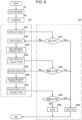
- Fig. 6 illustrates an inspection flow of the inspection device 40.
- the camera 42 that has received the inspection start signal captures an image of the tubular continuous body 24 at the facing position toward the abutting portion 34, and transmits data on the captured image to the image processor 48 (image capturing step S 1). Further, the illuminator 44 illuminates the abutting portion 34 in the illumination direction intersecting the image capturing direction of the camera 42 at the angle ⁇ equal to or smaller than 90° at the same timing as that of the image capturing step S1 or in advance (illumination step S2).
- the image processor 48 processes the captured image transmitted from the camera 42, and detects the shade 52 of the abutting portion 34 extending in the axial direction X of the tubular continuous body 24 (image processing step S3).
- the determiner 50 determines, based on the shade 52 detected by the image processor 48, whether the tubular continuous body 24 is good or defective (determination step S4). Step S31 to step S37 constituting the image processing step S3 and step S41 to step S45 constituting the determination step S4 are described below in detail.
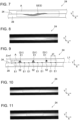
- Fig. 7 is a diagram for describing step S31 and step 41 in the inspection flow on the side surface of the tubular continuous body.
- step S31 an area S of the shade 52 is calculated and the process proceeds to step S41.
- step S41 determination is made as to whether the area S of the shade 52 is equal to or larger than a predetermined first threshold T1. When the determination result is affirmative (Yes) and S ⁇ T1 holds true, the process proceeds to step S44 to output information indicating that the tubular continuous body 24 is defective. Then, the inspection of the inspection region A to be inspected is terminated.
- Fig. 8 illustrates an example of a captured image when determination is made to indicate "defective" in the inspection described in Fig. 7 .
- a black or gray shade 52 expanding in the radial direction Y appears to meander in the axial direction X, and the area S of the shade 52 is equal to or larger than the first threshold T1.
- the outer web 28 is bonded insufficiently at the seam bonding portion 32 to cause a so-called burst state of the tubular continuous body 24 in which one end of the outer web 28 around the abutting portion 34 is curled up.
- step 41 determines whether the tubular continuous body 24 is rejected from the transport section of the manufacturing device for the tubular continuous body 24 is a defective product before the tubular continuous body 24 is formed into the tubular rod, the tubular element 4, and furthermore the article 1.
- the determination result in step 41 is negative (No) and S ⁇ T1 does not hold true, that is, the area S of the shade 52 is smaller than the first threshold T1
- Fig. 9 is a diagram for describing step S32 to step 34 and step 42 in the inspection flow on the side surface of the tubular continuous body 24.
- step S32 a plurality of first edges E1 located on the upper end side (one end side) of the shade 52 in the radial direction Y of the tubular continuous body 24 is detected with predetermined intervals d1 in the axial direction X.
- step S33 a first imaginary straight line L1 is created by linear approximation of the first edges E1.
- step S34 a first edge E1 in which a deviation amount ⁇ w1 in the radial direction Y between the first imaginary straight line L1 and the first edge E1 is larger than a predetermined second threshold T2, that is, ⁇ w1 > T2 holds true, is identified as a first defect D 1.
- step S42 determination is made as to whether the number ND 1 of first defects D1 is equal to or larger than a predetermined third threshold T3. When the determination result is affirmative (Yes) and ND1 ⁇ T3 holds true, the process proceeds to step S44 to output information indicating that the tubular continuous body 24 is defective. Then, the inspection of the inspection region A to be inspected is terminated.
- Fig. 10 to Fig. 13 illustrate examples of a captured image when determination is made to indicate "defective" in the inspection described in Fig. 9 .
- a black or gray region is present in the vicinity of the upper side of the abutting portion 34 located at the center in the radial direction Y of the tubular continuous body 24.
- glue scum soils the tubular continuous body 24.
- fine powder of the web material generated along with the manufacture of the tubular continuous body 24 or dust in the air may adhere to and be cured on the glue adhering to the vicinity of the upper side of the abutting portion 34 to soil the tubular continuous body 24.
- step S41 determination is made to indicate "good” in step S41 because the area S of the shade 52 is not large enough to presume the burst state of the tubular continuous body 24.
- the tubular continuous body 24 having this defect is rejected from the transport section of the manufacturing device for the tubular continuous body 24 as a defective product as in the case of the inspection described in Fig. 7 .
- the determination result in step 42 is negative (No) and ND 1 ⁇ T3 does not hold true, that is, the number ND 1 of first defects D1 is smaller than the third threshold T3
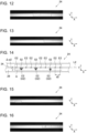
- Fig. 14 is a diagram for describing step S35 to step 37 and step 43 in the inspection flow on the side surface of the tubular continuous body 24.
- step S35 a plurality of second edges E2 located on the lower end side (other end side) of the shade 52 in the radial direction of the tubular continuous body 24 is detected with predetermined intervals d2 in the axial direction X.
- step S36 a second imaginary straight line L2 is created by linear approximation of the second edges E2.
- step S37 a second edge E2 in which a deviation amount ⁇ w2 in the radial direction Y between the second imaginary straight line L2 and the second edge E2 is larger than a predetermined second threshold T4, that is, ⁇ w2 > T4 holds true, is identified as a second defect D2.
- step S43 determination is made as to whether the number ND2 of second defects D2 is equal to or larger than a predetermined fifth threshold T5.
- the process proceeds to step S44 to output information indicating that the tubular continuous body 24 is defective. Then, the inspection of the inspection region A to be inspected is terminated.
- Fig. 15 and Fig. 16 illustrate examples of a captured image when determination is made to indicate "defective" in the inspection described in Fig. 14 .
- a black or gray region is present in the vicinity of the lower side of the abutting portion 34 located at the center in the radial direction Y of the tubular continuous body 24.
- glue scum soils the tubular continuous body 24.
- fine powder of the web material generated along with the manufacture of the tubular continuous body 24 or dust in the air may adhere to and be cured on the glue adhering to the vicinity of the lower side of the abutting portion 34 to soil the tubular continuous body 24.
- the tubular continuous body 24 is soiled in the vicinity of both the upper side and the lower side of the abutting portion 34. That is, even if determination is made that the soil in the vicinity of the upper side of the abutting portion 34 of the tubular continuous body 24 is in the permissible range in the inspection described in Fig. 7 , determination may be made that the tubular continuous body 24 is defective due to the soil in the vicinity of the lower side of the abutting portion 34.
- step S45 information indicating that the tubular continuous body 24 is good is output because the tubular continuous body 24 is neither burst nor soiled or the soil is in the permissible range. Then, the inspection of the inspection region A to be inspected is terminated. In this way, every time the control unit 46 outputs the inspection start signal at the interval of the predetermined period, the inspection of each inspection region A set successively on the tubular continuous body 24 that is being transported is sequentially performed in accordance with the inspection flow.
- the inspection device 40 of the embodiment inspects the tubular continuous body 24 serving as the tubular element 4 of the article 1 in the transport section. Further, the illuminator 44 illuminates the abutting portion 34 in the illumination direction intersecting the image capturing direction of the camera 42 at the angle ⁇ equal to or smaller than 90°. Therefore, defects such as the burst state or soil that may occur intermittently in the axial direction X of the tubular continuous body 24 are detected quickly and easily with the shade 52 of the abutting portion 34.
- the determiner 50 determines that the tubular continuous body 24 is defective because the burst state of the tubular continuous body 24 occurs.
- the burst state of the tubular continuous body 24 can be detected efficiently.
- the determiner 50 determines that the tubular continuous body 24 is defective because soil occurs due to glue scum etc. in the vicinity of the upper side of the abutting portion 34 of the tubular continuous body 24.
- the soil in the vicinity of the upper side of the abutting portion 34 of the tubular continuous body 24 is detected efficiently.
- the determiner 50 determines that the tubular continuous body 24 is defective because soil occurs due to glue scum etc. in the vicinity of the lower side of the abutting portion 34 of the tubular continuous body 24.
- the soil in the vicinity of the lower side of the abutting portion 34 of the tubular continuous body 24 is detected efficiently.
- the tubular continuous body 24 is inspected stepwise based on the area of the shade 52 of the abutting portion 34 and the first and second edges E1 and E2 on the upper end side and the lower end side of the shade. Therefore, defects extending or scattered in the axial direction X can be detected securely, and the tubular continuous body 24 that obviously has a defect is promptly rejected from the transport section. Thus, the efficiency of inspection of the tubular continuous body 24 can be improved, and the quality of the tubular continuous body 24 and furthermore the article 1 can be improved.
- the tubular element 4 is a paper tube in the above embodiment, but the double web may be made of a flexible material other than the paper web as long as the double tube having the abutting portion 34 is formed from the double web.
- the image capturing direction of the camera 42 and the illumination direction of the illuminator 44 intersect each other at the angle ⁇ equal to or smaller than 90°.
- the angle ⁇ ranges preferably from 45° to 90°.
Landscapes
- General Health & Medical Sciences (AREA)
- Health & Medical Sciences (AREA)
- Chemical & Material Sciences (AREA)
- Physics & Mathematics (AREA)
- Analytical Chemistry (AREA)
- Biochemistry (AREA)
- Life Sciences & Earth Sciences (AREA)
- General Physics & Mathematics (AREA)
- Immunology (AREA)
- Pathology (AREA)
- Engineering & Computer Science (AREA)
- Computer Vision & Pattern Recognition (AREA)
- Signal Processing (AREA)
- Toxicology (AREA)
- Investigating Materials By The Use Of Optical Means Adapted For Particular Applications (AREA)
Abstract
Description
- The present invention relates to an inspection device and an inspection method for a tubular continuous body, and more specifically, to an inspection device and an inspection method for inspecting, in a transport process, a tubular continuous body serving as a tubular element of a flavor inhalation article.
-
PTL 1 discloses a tubular continuous body made of double web materials that are an inner web and an outer web. With a manufacturing device described inPTL 1, a serial tubular continuous body is first formed, the tubular continuous body is cut into tubular rods in a transport section, an attachment process is performed to further connect other elements, and the tubular rod is further cut, thereby forming a tubular element constituting a flavor inhalation article. - The tubular continuous body is a double tube including an overlapping portion where the inner web and the outer web are bonded together with a shift in a circumferential direction, a seam bonding portion where an inner circumferential edge portion that is a region other than the overlapping portion on the inner circumferential surface of the outer web and an outer circumferential edge portion that is a region other than the overlapping portion on the outer circumferential surface of the inner web are bonded together while overlapping each other, and an abutting portion that adjoins the seam bonding portion and where both ends of the outer web in the circumferential direction abut against each other.
-
- On the outer circumferential surface of a normal tubular continuous body, the abutting portion appears as an ultrathin straight line in an axial direction. However, the paper widths of the inner web and the outer web may have variations or a small bonding misalignment may occur when the overlapping portion and the seam bonding portion are formed. In those cases, the width of the abutting portion increases and glue projecting off the seam bonding portion adheres to the abutting portion and its vicinity.
- The glue adhering to the abutting portion and its vicinity is cured into glue scum to soil the tubular continuous body. Further, fine powder of the web material generated along with the manufacture of the tubular continuous body or dust in the air may adhere to and be cured on the glue adhering to the abutting portion and its vicinity to soil the tubular continuous body.
- Further, the outer web may be bonded insufficiently at the seam bonding portion to cause a so-called burst state of the tubular continuous body in which one end of the outer web around the abutting portion is curled up. Those defects deteriorate the quality of the tubular continuous body, the tubular rod, the tubular element, and furthermore the flavor inhalation article. In a case where the tubular rod or the tubular element is inspected for those defects, the inspection efficiency significantly decreases and the productivity of the flavor inhalation article decreases. Therefore, there is a demand to detect and reject a defective product by inspection at the stage of the tubular continuous body.
- The present invention has been made in view of such problems, and has an object to provide an inspection device and an inspection method for a tubular continuous body in which the quality of the tubular continuous body can be improved by efficient inspection.
- To achieve the above object, an inspection device for a tubular continuous body according to one aspect is an inspection device that inspects a tubular continuous body serving as a tubular element of a flavor inhalation article in a transport section. The tubular continuous body is a double tube including an overlapping portion where an inner web and an outer web are bonded together with a shift in a circumferential direction, a seam bonding portion where an inner circumferential edge portion that is a region other than the overlapping portion on an inner circumferential surface of the outer web and an outer circumferential edge portion that is a region other than the overlapping portion on an outer circumferential surface of the inner web are bonded together while overlapping each other, and an abutting portion that adjoins the seam bonding portion and where both ends of the outer web in the circumferential direction abut against each other. The inspection device includes: a camera that captures an image of the tubular continuous body at a facing position toward the abutting portion; an illuminator that illuminates the abutting portion in an illumination direction intersecting an image capturing direction of the camera at an angle equal to or smaller than 90°; an image processor that processes the image captured by the camera and detects a shade of the abutting portion extending in an axial direction of the tubular continuous body; and a determiner that determines, based on the shade detected by the image processor, whether the tubular continuous body is good or defective.
- Further, an inspection method for a tubular continuous body according to one aspect is an inspection method for inspecting a tubular continuous body serving as a tubular element of a flavor inhalation article in a transport section. The tubular continuous body is a double tube including an overlapping portion where an inner web and an outer web are bonded together with a shift in a circumferential direction, a seam bonding portion where an inner circumferential edge portion that is a region other than the overlapping portion on an inner circumferential surface of the outer web and an outer circumferential edge portion that is a region other than the overlapping portion on an outer circumferential surface of the inner web are bonded together while overlapping each other, and an abutting portion that adjoins the seam bonding portion and where both ends of the outer web in the circumferential direction abut against each other. The inspection method includes: an image capturing step for capturing an image of the tubular continuous body at a facing position toward the abutting portion; an illumination step for illuminating the abutting portion in an illumination direction intersecting an image capturing direction in the image capturing step at an angle equal to or smaller than 90°; an image processing step for processing the image captured in the image capturing step and detecting a shade of the abutting portion extending in an axial direction of the tubular continuous body; and a determination step for determining, based on the shade detected in the image processing step, whether the tubular continuous body is good or defective.
- The tubular continuous body can be inspected efficiently, and the quality of the tubular continuous body can be improved.
-
- [
Fig. 1] Fig. 1 is a lateral sectional view of a flavor inhalation article. - [
Fig. 2] Fig. 2 is a vertical sectional view of a tubular element. - [
Fig. 3] Fig. 3 is a sectional view of a double web when the tubular element is developed in a radial direction. - [
Fig. 4] Fig. 4 is a schematic diagram of an inspection device for a tubular continuous body. - [
Fig. 5] Fig. 5 is a side view of the tubular continuous body. - [
Fig. 6] Fig. 6 illustrates an inspection flow of the inspection device. - [
Fig. 7] Fig. 7 is a diagram for describing step S31 and step 41 in the inspection flow on the side surface of the tubular continuous body. - [
Fig. 8] Fig. 8 illustrates an example of a captured image when determination is made to indicate "defective" in the inspection described inFig. 7 . - [
Fig. 9] Fig. 9 is a diagram for describing step S32 tostep 34 andstep 42 in the inspection flow on the side surface of the tubular continuous body. - [
Fig. 10] Fig. 10 illustrates an example of a captured image when determination is made to indicate "defective" in the inspection described inFig. 9 . - [
Fig. 11] Fig. 11 illustrates another example of the captured image ofFig. 10 . - [
Fig. 12] Fig. 12 illustrates another example of the captured image ofFig. 10 . - [
Fig. 13] Fig. 13 illustrates another example of the captured image ofFig. 10 . - [
Fig. 14] Fig. 14 is a diagram for describing step S35 to step 37 and step 43 in the inspection flow on the side surface of the tubular continuous body. - [
Fig. 15] Fig. 15 illustrates an example of a captured image when determination is made to indicate "defective" in the inspection described inFig. 14 . - [
Fig. 16] Fig. 16 illustrates another example of the captured image ofFig. 15 . -
Fig. 1 is a lateral sectional view of a flavor inhalation article 1 (hereinafter referred to also as "article"). Thearticle 1 includes aflavor element 2, atubular element 4, and afilter element 6 in this order from the left side inFig. 1 (distal end side of the article 1). Theflavor element 2 is formed by filling with a flavorraw material 8. The circumferential surface of the flavorraw material 8 is wrapped with wrappingpaper 10. Thearticle 1 may be of a non-combustion-heating type or a combustion-heating type. - In a case where the
article 1 is of the non-combustion-heating type, as illustrated inFig. 1 , a device to be used for heating the flavor element 2 (flavor inhaler) includes, for example, a needle-shaped heater 12.Fig. 1 illustrates only theheater 12 of the device. Thearticle 1 is set on the device and theflavor element 2 is heated by inserting theheater 12 thereto. In a case where thearticle 1 is of the combustion-heating type, theflavor element 2 is lit. Thus, the flavor component of the flavorraw material 8 is vaporized in thearticle 1. - In the case where the
article 1 is of the non-combustion-heating type, the flavorraw material 8 is, for example, shredded tobacco, an object obtained by shredding a tobacco sheet, or an object obtained by folding a tobacco sheet into gathers. The flavorraw material 8 may be an object obtained by adding a flavoring agent to a sheet made of pulp that does not contain tobacco, an object obtained by shredding a sheet made of a non-tobacco plant, or an object obtained by folding those sheets into gathers. - The
tubular element 4 forms an airflow path in thearticle 1 and is made of apaper tube 14 having a cylindrical shape. Thepaper tube 14 is made of a double paper web. Thetubular element 4 cools the flavor component volatilized in theflavor element 2 by heating to obtain an aerosol. Thefilter element 6 is a filter filled with afilling material 16. The circumferential surface of thefilter element 6 is wrapped withwrapping paper 18. Theelements article 1 to abut against each other, thereby forming a continuous body. - The
elements paper 20 on the circumferential surface of the continuous body. In thetubular element 4 and the tippingpaper 20, air passage holes 22 for taking air into thearticle 1 during inhalation from thearticle 1 are open in a radial direction Y of thearticle 1. Air taken into thearticle 1 from the outside through the air passage holes 22 cools the flavor component in theflavor element 2 and volatilized components of additives added to thetubular element 4 and thefilter element 6, thereby promoting aerosolization of those components. -
Fig. 2 is a vertical sectional view of thetubular element 4 andFig. 3 is a sectional view of a double web when thetubular element 4 is developed in the radial direction Y With the publicly known manufacturing device described above in PTL 1 (EP 3033952 A2 ), a serial tubularcontinuous body 24 is first formed, the tubularcontinuous body 24 is cut into tubular rods in a transport section of the manufacturing device, an attachment process is performed to further connect other elements, and the tubular rod is further cut, thereby forming thetubular element 4 constituting thearticle 1. That is,Fig. 2 also illustrates the vertical cross section of the tubularcontinuous body 24. - The tubular
continuous body 24 is a double tube formed from double paper webs that are aninner web 26 and anouter web 28, and includes an overlappingportion 30, aseam bonding portion 32, and an abuttingportion 34. The overlappingportion 30 is a portion where theinner web 26 and theouter web 28 are bonded together using abonding portion 36 with a shift in a circumferential direction inFig. 2 (width direction Z inFig. 3 ). - The
seam bonding portion 32 is a portion where an innercircumferential edge portion 28b that is a region other than the overlappingportion 30 on an innercircumferential surface 28a of theouter web 28 and an outercircumferential edge portion 26b that is a region other than the overlappingportion 30 on an outercircumferential surface 26a of theinner web 26 are bonded together while overlapping each other. The abuttingportion 34 is a portion that adjoins theseam bonding portion 32 and where both ends of theouter web 28 in the circumferential direction abut against each other. - In this way, the
inner web 26 and theouter web 28 are placed with a positional shift in the width direction Z, and the double web including the overlappingportion 30, the innercircumferential edge portion 28b, and the outercircumferential edge portion 26b is curved and bonded at theseam bonding portion 32. Thus, as illustrated inFig. 2 , the tubularcontinuous body 24 is formed by bonding theinner web 26 and theouter web 28 at theseam bonding portion 32 without irregularities. - Thus, the circumferential surface of the tubular
continuous body 24 is a smooth surface without irregularities, and the quality of thetubular element 4 is improved. Since thetubular element 4 is formed from the double web, the buckling strength of thetubular element 4 is increased and the function of thetubular element 4 as a support segment is enhanced compared with a case where thetubular element 4 is formed from a single web. -
Fig. 4 is a schematic diagram of aninspection device 40 for the tubularcontinuous body 24. Theinspection device 40 inspects, in a transport process, the tubularcontinuous body 24 transported in the transport section of the manufacturing device described above. Theinspection device 40 includes acamera 42, anilluminator 44, and acontrol unit 46. Thecontrol unit 46 includes animage processor 48 and adeterminer 50. Thecamera 42 is electrically connected to thecontrol unit 46, and captures an image of the tubularcontinuous body 24 at a facing position toward the abuttingportion 34. - The
illuminator 44 is, for example, a white LED illuminator that is electrically connected to thecontrol unit 46 and illuminates the abuttingportion 34 in an illumination direction (represented by a two-dot chain line) intersecting an image capturing direction of the camera 42 (represented by a chain line) at an angle α equal to or smaller than 90°. Theilluminator 44 may be supplied with electric power from an unillustrated power source without being connected to thecontrol unit 46. Further, an unillustrated display unit may be provided to display an image captured by thecamera 42. -
Fig. 5 is a side view of the tubularcontinuous body 24. On the circumferential surface of the normal tubularcontinuous body 24, the abuttingportion 34 appears as a straight line in the axial direction X. Theilluminator 44 illuminates the abuttingportion 34 in the illumination direction intersecting the image capturing direction of thecamera 42 at the angle α equal to or smaller than 90° and, when the tubularcontinuous body 24 is normal, the abuttingportion 34 is detected as a black orgray shade 52 having an ultrathin straight line shape in a monochrome image captured by thecamera 42. - When the inspection of the tubular
continuous body 24 is started, thecontrol unit 46 outputs an image capturing start signal every predetermined period (e.g., 21 msec). Every time the output image capturing start signal is received, thecamera 42 captures an image of the tubularcontinuous body 24 that is being transported. In the captured image transmitted from thecamera 42, theimage processor 48 sets an inspection region A having a predetermined distance d (e.g., 65 mm) in the axial direction X of the tubularcontinuous body 24. When an inspection start signal is received for the first time, theimage processor 48 detects an end surface position P of the tubularcontinuous body 24 based on the captured image. - Based on the end surface position P, the
image processor 48 corrects the position of the inspection region A to keep the distance d in the axial direction X of the inspection region A to be inspected next time onwards. By correcting the position of the inspection region A, the abuttingportion 34 can securely be positioned in the inspection region A even if the tubularcontinuous body 24 is slightly displaced in the radial direction Y in the transport process to cause so-called rod runout. Thus, the tubularcontinuous body 24 can be inspected over the entire region in the axial direction X without missing the inspection points. -
Fig. 6 illustrates an inspection flow of theinspection device 40. When the inspection of the tubularcontinuous body 24 is started, thecamera 42 that has received the inspection start signal captures an image of the tubularcontinuous body 24 at the facing position toward the abuttingportion 34, and transmits data on the captured image to the image processor 48 (image capturing step S 1). Further, theilluminator 44 illuminates the abuttingportion 34 in the illumination direction intersecting the image capturing direction of thecamera 42 at the angle α equal to or smaller than 90° at the same timing as that of the image capturing step S1 or in advance (illumination step S2). - Next, the
image processor 48 processes the captured image transmitted from thecamera 42, and detects theshade 52 of the abuttingportion 34 extending in the axial direction X of the tubular continuous body 24 (image processing step S3). Next, thedeterminer 50 determines, based on theshade 52 detected by theimage processor 48, whether the tubularcontinuous body 24 is good or defective (determination step S4). Step S31 to step S37 constituting the image processing step S3 and step S41 to step S45 constituting the determination step S4 are described below in detail. -
Fig. 7 is a diagram for describing step S31 and step 41 in the inspection flow on the side surface of the tubular continuous body. In step S31, an area S of theshade 52 is calculated and the process proceeds to step S41. In step S41, determination is made as to whether the area S of theshade 52 is equal to or larger than a predetermined first threshold T1. When the determination result is affirmative (Yes) and S ≥ T1 holds true, the process proceeds to step S44 to output information indicating that the tubularcontinuous body 24 is defective. Then, the inspection of the inspection region A to be inspected is terminated. -
Fig. 8 illustrates an example of a captured image when determination is made to indicate "defective" in the inspection described inFig. 7 . In the abuttingportion 34, a black orgray shade 52 expanding in the radial direction Y appears to meander in the axial direction X, and the area S of theshade 52 is equal to or larger than the first threshold T1. In this case, it is assumed that theouter web 28 is bonded insufficiently at theseam bonding portion 32 to cause a so-called burst state of the tubularcontinuous body 24 in which one end of theouter web 28 around the abuttingportion 34 is curled up. - This defect deteriorates the quality of the tubular
continuous body 24, the tubular rod, thetubular element 4, and furthermore thearticle 1. Therefore, the tubularcontinuous body 24 is rejected from the transport section of the manufacturing device for the tubularcontinuous body 24 as a defective product before the tubularcontinuous body 24 is formed into the tubular rod, thetubular element 4, and furthermore thearticle 1. When the determination result in step 41 is negative (No) and S ≥ T1 does not hold true, that is, the area S of theshade 52 is smaller than the first threshold T1, determination is made that there is a strong possibility that the burst state of the tubularcontinuous body 24 does not occur, and the process proceeds to step S32. -
Fig. 9 is a diagram for describing step S32 to step 34 andstep 42 in the inspection flow on the side surface of the tubularcontinuous body 24. In step S32, a plurality of first edges E1 located on the upper end side (one end side) of theshade 52 in the radial direction Y of the tubularcontinuous body 24 is detected with predetermined intervals d1 in the axial direction X. Next, in step S33, a first imaginary straight line L1 is created by linear approximation of the first edges E1. - Next, in step S34, a first edge E1 in which a deviation amount Δw1 in the radial direction Y between the first imaginary straight line L1 and the first edge E1 is larger than a predetermined second threshold T2, that is, Δw1 > T2 holds true, is identified as a
first defect D 1. Next, in step S42, determination is made as to whether thenumber ND 1 of first defects D1 is equal to or larger than a predetermined third threshold T3. When the determination result is affirmative (Yes) and ND1 ≥ T3 holds true, the process proceeds to step S44 to output information indicating that the tubularcontinuous body 24 is defective. Then, the inspection of the inspection region A to be inspected is terminated. -
Fig. 10 to Fig. 13 illustrate examples of a captured image when determination is made to indicate "defective" in the inspection described inFig. 9 . As indicated by boxes in the captured images ofFig. 10 to Fig. 13 , a black or gray region is present in the vicinity of the upper side of the abuttingportion 34 located at the center in the radial direction Y of the tubularcontinuous body 24. It is assumed that glue scum soils the tubularcontinuous body 24. It is also assumed that fine powder of the web material generated along with the manufacture of the tubularcontinuous body 24 or dust in the air may adhere to and be cured on the glue adhering to the vicinity of the upper side of the abuttingportion 34 to soil the tubularcontinuous body 24. - Regarding this soil, determination is made to indicate "good" in step S41 because the area S of the
shade 52 is not large enough to presume the burst state of the tubularcontinuous body 24. However, the tubularcontinuous body 24 having this defect is rejected from the transport section of the manufacturing device for the tubularcontinuous body 24 as a defective product as in the case of the inspection described inFig. 7 . When the determination result instep 42 is negative (No) andND 1 ≥ T3 does not hold true, that is, thenumber ND 1 of first defects D1 is smaller than the third threshold T3, determination is made that no soil occurs in the vicinity of the upper side of the abuttingportion 34 of the tubularcontinuous body 24 or the soil is in a permissible range, and the process proceeds to step S37. -
Fig. 14 is a diagram for describing step S35 to step 37 and step 43 in the inspection flow on the side surface of the tubularcontinuous body 24. In step S35, a plurality of second edges E2 located on the lower end side (other end side) of theshade 52 in the radial direction of the tubularcontinuous body 24 is detected with predetermined intervals d2 in the axial direction X. Next, in step S36, a second imaginary straight line L2 is created by linear approximation of the second edges E2. - Next, in step S37, a second edge E2 in which a deviation amount Δw2 in the radial direction Y between the second imaginary straight line L2 and the second edge E2 is larger than a predetermined second threshold T4, that is, Δw2 > T4 holds true, is identified as a second defect D2. Next, in step S43, determination is made as to whether the number ND2 of second defects D2 is equal to or larger than a predetermined fifth threshold T5. When the determination result is affirmative (Yes) and ND2 ≥ T5 holds true, the process proceeds to step S44 to output information indicating that the tubular
continuous body 24 is defective. Then, the inspection of the inspection region A to be inspected is terminated. -
Fig. 15 and Fig. 16 illustrate examples of a captured image when determination is made to indicate "defective" in the inspection described inFig. 14 . As indicated by a box in the captured image ofFig. 15 , a black or gray region is present in the vicinity of the lower side of the abuttingportion 34 located at the center in the radial direction Y of the tubularcontinuous body 24. It is assumed that glue scum soils the tubularcontinuous body 24. It is also assumed that fine powder of the web material generated along with the manufacture of the tubularcontinuous body 24 or dust in the air may adhere to and be cured on the glue adhering to the vicinity of the lower side of the abuttingportion 34 to soil the tubularcontinuous body 24. - As indicated by a box in the captured image of
Fig. 16 , the tubularcontinuous body 24 is soiled in the vicinity of both the upper side and the lower side of the abuttingportion 34. That is, even if determination is made that the soil in the vicinity of the upper side of the abuttingportion 34 of the tubularcontinuous body 24 is in the permissible range in the inspection described inFig. 7 , determination may be made that the tubularcontinuous body 24 is defective due to the soil in the vicinity of the lower side of the abuttingportion 34. - The tubular
continuous body 24 having this defect is rejected from the transport section of the manufacturing device for the tubularcontinuous body 24 as a defective product as in the case of the inspection described inFig. 9 . When the determination result in step 43 is negative (No) and ND2 ≥ T5 does not hold true, that is, the number ND2 of second defects D2 is smaller than the fifth threshold T5, the process proceeds to step S45. - In step S45, information indicating that the tubular
continuous body 24 is good is output because the tubularcontinuous body 24 is neither burst nor soiled or the soil is in the permissible range. Then, the inspection of the inspection region A to be inspected is terminated. In this way, every time thecontrol unit 46 outputs the inspection start signal at the interval of the predetermined period, the inspection of each inspection region A set successively on the tubularcontinuous body 24 that is being transported is sequentially performed in accordance with the inspection flow. - As described above, the
inspection device 40 of the embodiment inspects the tubularcontinuous body 24 serving as thetubular element 4 of thearticle 1 in the transport section. Further, theilluminator 44 illuminates the abuttingportion 34 in the illumination direction intersecting the image capturing direction of thecamera 42 at the angle α equal to or smaller than 90°. Therefore, defects such as the burst state or soil that may occur intermittently in the axial direction X of the tubularcontinuous body 24 are detected quickly and easily with theshade 52 of the abuttingportion 34. - Thus, it is possible to detect and securely reject the defect of the tubular
continuous body 24 at the stage of the tubularcontinuous body 24. Further, it is possible to implement improvement in the efficiency of inspection and the quality of the tubularcontinuous body 24 because the vicinity of the abuttingportion 34 that is likely to have defects is inspected intensively. Specifically, when the area S of theshade 52 is equal to or larger than the first threshold T1 in the determination step S4, thedeterminer 50 determines that the tubularcontinuous body 24 is defective because the burst state of the tubularcontinuous body 24 occurs. Thus, the burst state of the tubularcontinuous body 24 can be detected efficiently. - Further, when the
number ND 1 offirst defects D 1 identified at the first edges E1 on the upper end side of theshade 52 in the radial direction of the tubularcontinuous body 24 is equal to or larger than the third threshold T3 in the determination step S4, thedeterminer 50 determines that the tubularcontinuous body 24 is defective because soil occurs due to glue scum etc. in the vicinity of the upper side of the abuttingportion 34 of the tubularcontinuous body 24. Thus, the soil in the vicinity of the upper side of the abuttingportion 34 of the tubularcontinuous body 24 is detected efficiently. - Further, when the number ND2 of second defects D2 identified at the second edges E2 on the lower end side of the
shade 52 in the radial direction of the tubularcontinuous body 24 is equal to or larger than the fifth threshold T5 in the determination step S4, thedeterminer 50 determines that the tubularcontinuous body 24 is defective because soil occurs due to glue scum etc. in the vicinity of the lower side of the abuttingportion 34 of the tubularcontinuous body 24. Thus, the soil in the vicinity of the lower side of the abuttingportion 34 of the tubularcontinuous body 24 is detected efficiently. - In this way, the tubular
continuous body 24 is inspected stepwise based on the area of theshade 52 of the abuttingportion 34 and the first and second edges E1 and E2 on the upper end side and the lower end side of the shade. Therefore, defects extending or scattered in the axial direction X can be detected securely, and the tubularcontinuous body 24 that obviously has a defect is promptly rejected from the transport section. Thus, the efficiency of inspection of the tubularcontinuous body 24 can be improved, and the quality of the tubularcontinuous body 24 and furthermore thearticle 1 can be improved. - Although the description of the embodiment will end, the embodiment is not limitative and various modifications may be made without departing from the gist. For example, the
tubular element 4 is a paper tube in the above embodiment, but the double web may be made of a flexible material other than the paper web as long as the double tube having the abuttingportion 34 is formed from the double web. - Further, the image capturing direction of the
camera 42 and the illumination direction of theilluminator 44 intersect each other at the angle α equal to or smaller than 90°. To maximize the visibility of theshade 52 and improve the inspection accuracy, the angle α ranges preferably from 45° to 90°. -
- 1
- flavor inhalation article
- 4
- tubular element
- 24
- tubular continuous body
- 26
- inner web
- 26a
- outer circumferential surface
- 26b
- outer circumferential edge portion
- 28
- outer web
- 28a
- inner circumferential surface
- 28b
- inner circumferential edge portion
- 30
- overlapping portion
- 32
- seam bonding portion
- 34
- abutting portion
- 40
- inspection device
- 42
- camera
- 44
- illuminator
- 48
- image processor
- 50
- determiner
- 52
- shade
- α
- angle
- D1
- first defect
- D2
- second defect
- d1
- predetermined interval
- d2
- predetermined interval
- E1
- first edge
- E2
- second edge
- L1
- first imaginary straight line
- L2
- second imaginary straight line
-
ND 1 - number of first defects
- ND2
- number of second defects
- S
- area
-
S 1 - image capturing step
- S2
- illumination step
- S3
- image processing step
- S4
- determination step
- T1
- first threshold
- T2
- second threshold
- T3
- third threshold
- T4
- fourth threshold
- T5
- fifth threshold
- Δw1
- deviation amount
- Δw2
- deviation amount
- X
- axial direction
- Y
- radial direction
Claims (8)
- An inspection device that inspects a tubular continuous body serving as a tubular element of a flavor inhalation article in a transport section,the tubular continuous body being a double tube includingan overlapping portion where an inner web and an outer web are bonded together with a shift in a circumferential direction,a seam bonding portion where an inner circumferential edge portion that is a region other than the overlapping portion on an inner circumferential surface of the outer web and an outer circumferential edge portion that is a region other than the overlapping portion on an outer circumferential surface of the inner web are bonded together while overlapping each other, andan abutting portion that adjoins the seam bonding portion and where both ends of the outer web in the circumferential direction abut against each other,the inspection device for the tubular continuous body comprising:a camera that captures an image of the tubular continuous body at a facing position toward the abutting portion;an illuminator that illuminates the abutting portion in an illumination direction intersecting an image capturing direction of the camera at an angle equal to or smaller than 90°;an image processor that processes the image captured by the camera and detects a shade of the abutting portion extending in an axial direction of the tubular continuous body; anda determiner that determines, based on the shade detected by the image processor, whether the tubular continuous body is good or defective.
- The inspection device for the tubular continuous body according to claim 1, whereinthe image processor calculates an area of the shade, andwhen the area of the shade is equal to or larger than a predetermined first threshold, the determiner determines that the tubular continuous body is defective.
- The inspection device for the tubular continuous body according to claim 2, whereinthe image processor detects, with predetermined intervals in the axial direction, a plurality of first edges located on one end side of the shade in a radial direction of the tubular continuous body, creates a first imaginary straight line by linear approximation of the first edges, and identifies, as a first defect, the first edge in which a deviation amount in the radial direction between the first imaginary straight line and the first edge is larger than a predetermined second threshold, andwhen the number of the first defects is equal to or larger than a predetermined third threshold, the determiner determines that the tubular continuous body is defective.
- The inspection device for the tubular continuous body according to claim 3, whereinthe image processor detects, with predetermined intervals in the axial direction, a plurality of second edges located on another end side of the shade in the radial direction, creates a second imaginary straight line by linear approximation of the second edges, and identifies, as a second defect, the second edge in which a deviation amount in the radial direction between the second imaginary straight line and the second edge is larger than a predetermined fourth threshold, andwhen the number of the second defects is equal to or larger than a predetermined fifth threshold, the determiner determines that the tubular continuous body is defective.
- An inspection method for inspecting a tubular continuous body serving as a tubular element of a flavor inhalation article in a transport section,the tubular continuous body being a double tube includingan overlapping portion where an inner web and an outer web are bonded together with a shift in a circumferential direction,a seam bonding portion where an inner circumferential edge portion that is a region other than the overlapping portion on an inner circumferential surface of the outer web and an outer circumferential edge portion that is a region other than the overlapping portion on an outer circumferential surface of the inner web are bonded together while overlapping each other, andan abutting portion that adjoins the seam bonding portion and where both ends of the outer web in the circumferential direction abut against each other,the inspection method for the tubular continuous body comprising:an image capturing step for capturing an image of the tubular continuous body at a facing position toward the abutting portion;an illumination step for illuminating the abutting portion in an illumination direction intersecting an image capturing direction in the image capturing step at an angle equal to or smaller than 90°;an image processing step for processing the image captured in the image capturing step and detecting a shade of the abutting portion extending in an axial direction of the tubular continuous body; anda determination step for determining, based on the shade detected in the image processing step, whether the tubular continuous body is good or defective.
- The inspection method for the tubular continuous body according to claim 5, whereinin the image processing step, an area of the shade is calculated, andin the determination step, when the area of the shade is equal to or larger than a predetermined first threshold, determination is made that the tubular continuous body is defective.
- The inspection method for the tubular continuous body according to claim 6, whereinin the image processing step, a plurality of first edges located on one end side of the shade in a radial direction of the tubular continuous body is detected with predetermined intervals in the axial direction, a first imaginary straight line is created by linear approximation of the first edges, and the first edge in which a deviation amount in the radial direction between the first imaginary straight line and the first edge is larger than a predetermined second threshold is identified as a first defect, andin the determination step, when the number of the first defects is equal to or larger than a predetermined third threshold, determination is made that the tubular continuous body is defective.
- The inspection method for the tubular continuous body according to claim 7, whereinin the image processing step, a plurality of second edges located on another end side of the shade in the radial direction of the tubular continuous body is detected with predetermined intervals in the axial direction, a second imaginary straight line is created by linear approximation of the second edges, and the second edge in which a deviation amount in the radial direction between the second imaginary straight line and the second edge is larger than a predetermined fourth threshold is identified as a second defect, andin the determination step, when the number of the second defects is equal to or larger than a predetermined fifth threshold, determination is made that the tubular continuous body is defective.
Applications Claiming Priority (1)
| Application Number | Priority Date | Filing Date | Title |
|---|---|---|---|
| PCT/JP2021/042969 WO2023095200A1 (en) | 2021-11-24 | 2021-11-24 | Inspection device for tubular continuous object and inspection method |
Publications (2)
| Publication Number | Publication Date |
|---|---|
| EP4437861A1 true EP4437861A1 (en) | 2024-10-02 |
| EP4437861A4 EP4437861A4 (en) | 2025-09-03 |
Family
ID=86539058
Family Applications (1)
| Application Number | Title | Priority Date | Filing Date |
|---|---|---|---|
| EP21965574.3A Pending EP4437861A4 (en) | 2021-11-24 | 2021-11-24 | Inspection device for tubular continuous object and inspection method |
Country Status (2)
| Country | Link |
|---|---|
| EP (1) | EP4437861A4 (en) |
| WO (1) | WO2023095200A1 (en) |
Family Cites Families (7)
| Publication number | Priority date | Publication date | Assignee | Title |
|---|---|---|---|---|
| FR978547A (en) * | 1948-11-18 | 1951-04-16 | Carnaud & Forges | Improvements in the manufacture of cardboard and metal boxes |
| DE69320528T2 (en) * | 1992-05-15 | 1999-02-25 | Philip Morris Products Inc., Richmond, Va. | Device and method for the optical inspection of cylindrical surfaces |
| DE102005046581A1 (en) * | 2005-09-28 | 2007-03-29 | Hauni Maschinenbau Ag | Multi-segmented filters properties measuring device for tobacco processing industry, has laser light source forming line of electromagnetic radiation on filters, where extension of line is smaller than diameter of filters |
| IT1393013B1 (en) * | 2008-12-18 | 2012-04-11 | Gd Spa | METHOD FOR SETTING UP AND MANAGEMENT OF THE CONTROL DEVICE IN A MACHINE FOR THE PRODUCTION OF SMOKE ITEMS. |
| DE102014226019A1 (en) | 2014-12-16 | 2016-06-16 | Hauni Maschinenbau Ag | Doppellagiges tube of the tobacco processing industry and apparatus and method for producing such a tube |
| DE102016124051A1 (en) * | 2016-12-12 | 2018-06-14 | Hauni Maschinenbau Gmbh | Doppellagiges tube of the tobacco processing industry and method for producing such a tube |
| DE102018132297B4 (en) * | 2017-12-20 | 2023-03-02 | G.D S.P.A. | Method and machine for manufacturing sections of cylindrical tubular rod suitable for manufacturing generally cylindrical smoking articles |
-
2021
- 2021-11-24 EP EP21965574.3A patent/EP4437861A4/en active Pending
- 2021-11-24 WO PCT/JP2021/042969 patent/WO2023095200A1/en not_active Ceased
Also Published As
| Publication number | Publication date |
|---|---|
| WO2023095200A1 (en) | 2023-06-01 |
| EP4437861A4 (en) | 2025-09-03 |
Similar Documents
| Publication | Publication Date | Title |
|---|---|---|
| JP5817384B2 (en) | Box body quality inspection equipment | |
| EP2199883A1 (en) | A method of setting up and managing the inspection device in a machine for manufacturing tobacco products | |
| JP4030455B2 (en) | Box sheet gluing inspection device | |
| WO2023095200A1 (en) | Inspection device for tubular continuous object and inspection method | |
| ES2961355T3 (en) | Inspection station and method for inspecting sheet material | |
| JP2013177148A (en) | Packaging sheet, package using the packaging sheet and inspection equipment for the package | |
| JP2015087147A (en) | Inspection device and PTP packaging machine | |
| JP2003291929A (en) | Package inspection method and device | |
| JP5227246B2 (en) | Glue application inspection device | |
| JP5771490B2 (en) | Inspection device for raising state of web member relating to hygiene article, and inspection method | |
| CN109068722A (en) | The device and method of optical detection are carried out for the bar form articles to the tobacco industry | |
| JP2022042521A (en) | Method for manufacturing sheet-like member | |
| JP3834692B2 (en) | Sheet monitoring apparatus, sheet conveying apparatus, and sheet monitoring method | |
| JP4261221B2 (en) | Packaging inspection method and inspection device | |
| JP2003322510A (en) | Sheet roll inspection method and inspection apparatus | |
| US5654802A (en) | Method and device for inspecting bags | |
| JP6289919B2 (en) | Hot melt inspection apparatus and method | |
| EP4445754A1 (en) | Inspection apparatus and inspection method for filter rod | |
| JP6168395B2 (en) | Blank manufacturing system and blank manufacturing method | |
| JP6763064B1 (en) | Inspection equipment and packaging manufacturing equipment | |
| EP4632360A1 (en) | Method for performing an optical analysis on an article of the tobacco industry and machine for making articles of the tobacco industry | |
| JP4316282B2 (en) | Corrugated sheet sheet processing line position inspection device | |
| JP3754842B2 (en) | Method and apparatus for determining welding state of can body | |
| JPH0912015A (en) | Device for detecting the edge failure of the end of the package | |
| EP4437862A1 (en) | Inspection device and inspection method for filter |
Legal Events
| Date | Code | Title | Description |
|---|---|---|---|
| STAA | Information on the status of an ep patent application or granted ep patent |
Free format text: STATUS: THE INTERNATIONAL PUBLICATION HAS BEEN MADE |
|
| PUAI | Public reference made under article 153(3) epc to a published international application that has entered the european phase |
Free format text: ORIGINAL CODE: 0009012 |
|
| STAA | Information on the status of an ep patent application or granted ep patent |
Free format text: STATUS: REQUEST FOR EXAMINATION WAS MADE |
|
| 17P | Request for examination filed |
Effective date: 20240514 |
|
| AK | Designated contracting states |
Kind code of ref document: A1 Designated state(s): AL AT BE BG CH CY CZ DE DK EE ES FI FR GB GR HR HU IE IS IT LI LT LU LV MC MK MT NL NO PL PT RO RS SE SI SK SM TR |
|
| DAV | Request for validation of the european patent (deleted) | ||
| DAX | Request for extension of the european patent (deleted) | ||
| A4 | Supplementary search report drawn up and despatched |
Effective date: 20250801 |
|
| RIC1 | Information provided on ipc code assigned before grant |
Ipc: A24C 5/34 20060101AFI20250728BHEP Ipc: A24D 3/02 20060101ALI20250728BHEP Ipc: G01N 21/952 20060101ALI20250728BHEP Ipc: G01N 21/88 20060101ALI20250728BHEP |