EP4437840A1 - Securing mechanism and pet loading accessory using the securing mechanism - Google Patents
Securing mechanism and pet loading accessory using the securing mechanism Download PDFInfo
- Publication number
- EP4437840A1 EP4437840A1 EP24160335.6A EP24160335A EP4437840A1 EP 4437840 A1 EP4437840 A1 EP 4437840A1 EP 24160335 A EP24160335 A EP 24160335A EP 4437840 A1 EP4437840 A1 EP 4437840A1
- Authority
- EP
- European Patent Office
- Prior art keywords
- blocking portion
- substantially vertical
- securing mechanism
- vertical segment
- loading accessory
- Prior art date
- Legal status (The legal status is an assumption and is not a legal conclusion. Google has not performed a legal analysis and makes no representation as to the accuracy of the status listed.)
- Pending
Links
Images




Classifications
-
- A—HUMAN NECESSITIES
- A01—AGRICULTURE; FORESTRY; ANIMAL HUSBANDRY; HUNTING; TRAPPING; FISHING
- A01K—ANIMAL HUSBANDRY; AVICULTURE; APICULTURE; PISCICULTURE; FISHING; REARING OR BREEDING ANIMALS, NOT OTHERWISE PROVIDED FOR; NEW BREEDS OF ANIMALS
- A01K1/00—Housing animals; Equipment therefor
- A01K1/02—Pigsties; Dog-kennels; Rabbit-hutches or the like
- A01K1/0236—Transport boxes, bags, cages, baskets, harnesses for animals; Fittings therefor
- A01K1/0272—Boxes, bags, cages, baskets, harnesses especially adapted for transport in or on automobiles
-
- B—PERFORMING OPERATIONS; TRANSPORTING
- B60—VEHICLES IN GENERAL
- B60R—VEHICLES, VEHICLE FITTINGS, OR VEHICLE PARTS, NOT OTHERWISE PROVIDED FOR
- B60R22/00—Safety belts or body harnesses in vehicles
- B60R22/10—Safety belts or body harnesses in vehicles specially adapted for children or animals
-
- A—HUMAN NECESSITIES
- A01—AGRICULTURE; FORESTRY; ANIMAL HUSBANDRY; HUNTING; TRAPPING; FISHING
- A01K—ANIMAL HUSBANDRY; AVICULTURE; APICULTURE; PISCICULTURE; FISHING; REARING OR BREEDING ANIMALS, NOT OTHERWISE PROVIDED FOR; NEW BREEDS OF ANIMALS
- A01K1/00—Housing animals; Equipment therefor
- A01K1/02—Pigsties; Dog-kennels; Rabbit-hutches or the like
- A01K1/0236—Transport boxes, bags, cages, baskets, harnesses for animals; Fittings therefor
-
- B—PERFORMING OPERATIONS; TRANSPORTING
- B60—VEHICLES IN GENERAL
- B60R—VEHICLES, VEHICLE FITTINGS, OR VEHICLE PARTS, NOT OTHERWISE PROVIDED FOR
- B60R22/00—Safety belts or body harnesses in vehicles
- B60R22/18—Anchoring devices
- B60R2022/1818—Belt guides
-
- B—PERFORMING OPERATIONS; TRANSPORTING
- B60—VEHICLES IN GENERAL
- B60R—VEHICLES, VEHICLE FITTINGS, OR VEHICLE PARTS, NOT OTHERWISE PROVIDED FOR
- B60R22/00—Safety belts or body harnesses in vehicles
- B60R22/18—Anchoring devices
Definitions
- the present invention relates to the technical field of pet products, and more specifically, to a securing mechanism and a pet loading accessory using the securing mechanism.
- Pet loading accessories such as pet carriers and pet sofas, are commonly used to load and carry pets. In addition to the loading and carrying function, sometimes it is also necessary to place the pet loading accessories on the seats of vehicles to meet the needs of transporting pets in vehicles.
- a strap-like structure is usually used and connected to the seat belt to secure the pet loading accessory.
- the use of a strap-like structure to secure the pet loading accessory does not always provide a reliable securing effect due to the softness and flexibility of the seat belt and the strap-like structure.
- mechanical structures that are used for securing the pet loading accessory such as a rotating arm assembly that is pivotally mounted on an axis to connect and disconnect the pet loading accessory to the seat belt.
- the design of such assembly is complex and expensive due to the presence of several structures and the inconvenience of operation.
- the present invention provides a securing mechanism and a pet loading accessory using the securing mechanism.
- a securing mechanism for a pet loading accessory includes a base, a first blocking portion, and a second blocking portion.
- the base is provided with a through hole.
- the first blocking portion preferably includes a substantially horizontal segment and a substantially vertical segment.
- the first end of the substantially horizontal segment of the first blocking portion is fixedly connected to the base, and the second end of the substantially horizontal segment of the first blocking portion is integrally formed with the first end of the substantially vertical segment of the first blocking portion to form a first joint and configure the first blocking portion in an L-shaped bending structure.
- the second blocking portion includes a substantially horizontal segment and a substantially vertical segment.
- the first end of the substantially horizontal segment of the second blocking portion is fixedly connected to the base, and the second end of the substantially horizontal segment of the second blocking portion is integrally formed with the first end of the substantially vertical segment of the second blocking portion to form a second joint and configure the second blocking portion in an L-shaped bending structure.
- the second end of the substantially vertical segment of the first blocking portion and the second end of the substantially vertical segment of the second blocking portion are arranged apart from and opposite to each other in an approaching manner.
- a securing groove is preferably formed between the first blocking portion, the second blocking portion, and the base, and a communication gap communicating with the securing groove is formed between the second end of the substantially vertical segment of the first blocking portion and the second end of the substantially vertical segment of the second blocking portion.
- the length of the substantially vertical segment of the first blocking portion is preferably greater than, equal to, or less than the length of the substantially vertical segment of the second blocking portion.
- substantially vertical segment of the first blocking portion and the substantially vertical segment of the second blocking portion are preferably both arranged parallel to the base.
- the base is preferably provided with two bolt holes.
- the second end of the substantially vertical segment of the first blocking portion is preferably parallel to the substantially horizontal segment of the first blocking portion, and the second end of the substantially vertical segment of the second blocking portion is parallel to the substantially horizontal segment of the second blocking portion.
- the surface of the second end of the substantially vertical segment of the first blocking portion is preferably a rounded surface, and the surface of the second end of the substantially vertical segment of the second blocking portion is preferably an inclined surface tilted towards the securing groove.
- the surface of the second end of the substantially vertical segment of the first blocking portion is preferably an inclined surface tilted towards the securing groove, and the surface of the second end of the substantially vertical segment of the second blocking portion is preferably a rounded surface.
- the second end of the substantially vertical segment of the first blocking portion is preferably parallel or oblique with respect to the substantially horizontal segment of the first blocking portion
- the second end of the substantially vertical segment of the second blocking portion is preferably parallel or oblique with respect to the substantially horizontal segment of the second blocking portion.
- the securing mechanism preferably includes a closed sliding sleeve slidably sleeved on the substantially vertical segment of the first blocking portion, and the closed sliding sleeve is preferably provided with a card slot.
- the second blocking portion is preferably provided with a card hook, and the card hook is preferably fixedly provided at the second end of the substantially vertical segment of the second blocking portion.
- a securing mechanism for a pet loading accessory includes a base, a first blocking portion, and a second blocking portion.
- the first blocking portion and the second blocking portion are in a staggered configuration.
- the first blocking portion preferably includes a substantially U-shaped segment and a substantially vertical segment.
- the first end of the substantially U-shaped segment of the first blocking portion is preferably fixedly connected to the base, and the second end of the substantially U-shaped segment of the first blocking portion is preferably integrally formed with the first end of the substantially vertical segment of the first blocking portion to form a first joint and configure the first blocking portion in a hook-like shape.
- the second blocking portion preferably includes a substantially U-shaped segment and a substantially vertical segment.
- the first end of the substantially U-shaped segment of the second blocking portion is preferably fixedly connected to the base, and the second end of the substantially U-shaped segment of the second blocking portion is preferably integrally formed with the first end of the substantially vertical segment of the second blocking portion to form a second joint and configure the second blocking portion in a hook-like shape.
- the second end of the substantially vertical segment of the first blocking portion and the second end of the substantially vertical segment of the second blocking portion are preferably arranged in the staggered configuration in an approaching manner.
- a securing groove is preferably formed between the first blocking portion, the second blocking portion, and the base, and a communication gap communicating with the securing groove is preferably formed between the second end of the substantially vertical segment of the first blocking portion and the second end of the substantially vertical segment of the second blocking portion.
- At least one of the second end of the substantially vertical segment of the first blocking portion and the second end of the substantially vertical segment of the second blocking portion preferably turns away to achieve the staggered configuration.
- a protrusion is preferably provided on the substantially vertical segment of the first blocking portion and set inside the securing groove.
- the protrusion preferably is a convex ridge structure protruding from the side facing the base and adjacent to the second end of the second blocking portion.
- a securing mechanism for a pet loading accessory includes a body.
- the body includes a fixing end and a movable end, the fixing end is fixedly connected to the pet loading accessory, and the movable end is detachably connected to the pet loading accessory.
- the body is preferably made of a flexible and non-elastic material. The use of flexible and non-elastic material can reduce the relative movement between the securing mechanism and the safety belt of a vehicle during use and enhance the securing effect of the securing mechanism on the safety belt.
- the fixing end is preferably fixedly connected to the pet loading accessory by an adhesive, a suture, or the like.
- the fixing end is preferably integrally formed with pet loading accessory.
- the movable end is preferably detachably connected to the pet loading accessory by a hook or a loop fastener, a button, or the like.
- the present invention provides a pet loading accessory using any of the above securing mechanisms.
- the present invention has the following advantages:
- a pet loading accessory includes the loading body 1 and the securing mechanism 2.
- the securing mechanism 2 is arranged on the outer edge of the loading body 1 and is used for securing the pet loading accessory with a strap-like body used for securing.
- the securing mechanism 2 can be placed at any position of the loading body 1 as required.
- the securing mechanism 2 can be a fitting attached to the loading body 1 or a structure integrally formed with the loading body 1.
- the types of the pet loading accessory include a pet sofa, a pet carrier, a pet transport box with vehicle functions, etc.
- a pet sofa that can be carried in a vehicle is used as an example for illustration.
- FIG. 1 the pet loading accessory is placed on the vehicle seat 3.
- the three-point safety belt 4 of the vehicle seat 3 is inserted into the safety belt buckle 5 and is in a roughly horizontal position, which is the strap-like body mentioned above.
- the securing mechanism 2 is used to secure the pet loading accessory by cooperating with the roughly horizontal section of the three-point safety belt 4, so that the loading body 1 is secured by the retraction force of the three-point safety belt 4 during normal use and by the cooperation of the securing mechanism 2 and the three-point safety belt 4 being locked in the case of an emergency.
- the side of the peripheral edge of the pet loading accessory facing the direction of vehicle travel is defined as the front side of the loading body 1.
- two or more securing mechanisms 2 can be used.
- two securing mechanisms 2 are used and respectively arranged on the front side of the loading body 1, and the two securing mechanisms 2 are set at approximately the same height.
- the securing mechanism 2 is an independently manufactured element, which is locked on the front side of the loading body 1 by screws or similar fastening members.
- the pet loading accessory is also secured by the webbing structure 6 hung on the headrest of the vehicle seat 3.
- the securing mechanism 2 includes the base 21, the first blocking portion 22, and the second blocking portion 23.
- the first blocking portion 22 and the second blocking portion 23 are configured in an L-shaped bending structure.
- the first blocking portion 22 has the substantially horizontal segment 221 and the substantially vertical segment 222 that are connected to configure the first blocking portion 22 in the L shape.
- the front end 22a of the first blocking portion 22 is fixedly arranged on the base 21, the substantially horizontal segment 221 is formed by extending outwardly from the front end 22a to the joint 22b of the first blocking portion 22, and the substantially vertical segment 222 is formed by extending from the joint 22b to the rear end 22c of the first blocking portion 22.
- the substantially vertical segment 222 is parallel to and spaced apart from the base 21, and the parallel arrangement can be roughly parallel or slightly inclined relative to the base21.
- the second blocking portion 23 has the substantially horizontal segment 231 and the substantially vertical segment 232 that are connected to configure the first blocking portion 23 in an L-shaped bending structure.
- the front end 23a of the second blocking portion 23 is fixedly arranged on the base 21, the substantially horizontal segment 231 is formed by extending outwardly from the front end 23a to the joint 23b of the second blocking portion 23, and the substantially vertical segment 232 is formed by extending from the joint 23b to the rear end 23c of the second blocking portion 23.
- the substantially vertical segment 232 is parallel to and spaced apart from the base 21, and the parallel arrangement can be roughly parallel or slightly inclined relative to the base21.
- the rear end 22c of the first blocking portion 22 and the rear end 23c of the second blocking portion 23 are arranged apart from and opposite to each other in an approaching manner.
- the securing groove 220 is formed between the bending structure of the first blocking portion 22, the bending structure of the second blocking portion 23, and the base 21.
- the communication gap 20 communicating with the securing groove 220 is formed between the rear end 22c of the first blocking portion 22 and the rear end 23c of the second blocking portion 23.
- the length of the substantially vertical segment 222 of the first blocking portion 22 and the length of the substantially vertical segment 232 of the second blocking portion 23 can be adjusted as needed.
- the length of the substantially vertical segment 222 can be greater than, equal to, or less than that of the substantially vertical segment 232. In the present embodiment, the length of the substantially vertical segment 222 is greater than that of the substantially vertical segment 232.
- the middle and lower part of the securing groove 220 which is the space formed between the bending structure of the first blocking portion 22 and the base 21, is mainly used to accommodate the roughly horizontal section of the three-point seat belt 4.
- the second blocking portion 23 mainly cooperates with the first blocking portion 22 to prevent the roughly horizontal section of the three-point seat belt 4 from slipping out from the top of the first blocking portion 22. Therefore, the length of the substantially vertical segment 222 of the first blocking portion 22 is set to be greater than that of the substantially vertical segment 232 of the second blocking portion 23.
- the first blocking portion 22 and the second blocking portion 23 are both in a bent plate structure.
- the base 21 is in a strip plate structure.
- the substantially vertical segment 222 and the substantially vertical segment 232 are both arranged parallel to the base 21.
- the base 21, the first blocking portion 22, and the second blocking portion 23 are integrally molded.
- the base 21 is provided with the through hole 211 and two bolt holes 212.
- the shape of the through hole 211 and the bolt holes 212 can be selected as needed. In the present embodiment, the through hole 211 is square and the bolt holes are circular.
- the square through hole 211 and the bolt holes 212 penetrate the thickness direction of the base 21, and the square through hole 211 is located in the middle of the base 21 and is connected to the front end 22a of the first blocking portion 22 and the front end 23a of the second blocking portion 23.
- the square through hole 211 is connected to the securing groove 220.
- the two bolt holes 212 are located at two ends of the base 21, respectively. Since the securing mechanism 2 is an integrally molded structure, the setting of the square through hole 211 can facilitate the demolding of the securing mechanism 2 from a molding die and also save injection molding materials.
- the securing mechanism 2 can be secured in place by inserting and fastening bolts into the bolt holes 212.
- the first blocking portion 22 is located below the second blocking portion 23.
- the substantially vertical segment 222 of the first blocking portion 22 is longer that the substantially vertical segment 232 of the second blocking portion 23, which allows over half of the securing groove 220 to be used to safely accommodate the roughly horizontal section of the three-point safety belt 4.
- the securing mechanism 2 is secured by bolts with the back of the base 21 in contact with the loading body 1 of the pet loading accessory.
- the surface of the rear end 22c of the first blocking portion 22 and the surface of the rear end 23c of the second blocking portion 23 are designed as rounded surfaces or inclined surfaces tilted towards the location of the securing groove 220.
- the surface of the rear end 22c of the first blocking portion 22 is designed as a rounded surface and the surface of the rear end 23c of the second blocking portion 23 is designed as an inclined surface.
- the width of the roughly horizontal section of the three-point safety belt 4 is greater than the distance between the joint 22b of the first blocking portion 22 and the lowest point of the rear end 23c of the second blocking portion 23, but less than the distance between the joint 22b of the first blocking portion 22 and the joint 23b of the second blocking portion 23.
- the width of the roughly horizontal section of the three-point safety belt 4 is at least 10 mm greater than the distance between the joint 22b of the first blocking portion 22 and the lowest point of the rear end 23b of the second blocking portion 23.
- the projection of the communication gap 20 on the base 21 is roughly perpendicular to the length direction of the base 21, that is, the rear end 22c of the first blocking portion 22 and the rear end 23c of the second blocking portion 23 are both perpendicular to the length direction of the base 21, the distance between the joint 22b of the first blocking portion 22 and the lowest point of the rear end 23c of the second blocking portion 23 actually refers to the distance between the joint 22b of the first blocking portion 22 and the rear end 23c of the second blocking portion 23.
- embodiment 2 Referring to FIG. 4 , the main differences between embodiment 2 and embodiment 1 are as follows:
- the securing mechanism 2 for a pet loading accessory which is identical to the pet loading accessory in embodiment 1 is provided.
- the securing mechanism 2 includes the base 21, the first blocking portion 22, the second blocking portion 23, and the closed sliding sleeve 24.
- the first blocking portion 22 and the second blocking portion 23 both have a bending plate-like structure extending along an L shape, while the base 21 has a strip-shaped plate-like structure.
- the securing mechanism 2 is integrally formed by an injection molding.
- the base 21 and the first blocking portion 22 are identical to the base 21 and the first blocking portion 22 in embodiment 1, and the second blocking portion 23 differs from the second blocking portion 23 in embodiment 1 only in that the card hook 233 is further provided on the second blocking portion 23.
- the closed sliding sleeve 24 is slidably sleeved on the outside of the first blocking portion 22.
- the card hook can be provided on the closed sliding sleeve and the card slot can be provided on the second blocking portion.
- the closed sliding sleeve 24 is used to close the communication gap 20. Since the length of the substantially vertical segment 222 of the first blocking portion 22 is greater than that of the substantially vertical segment 232 of the second blocking portion 23, the closed sliding sleeve 24 is preferably slidably sleeved on the substantially vertical segment 222 of the first blocking portion 22.
- the communication gap 20 can be closed by the closed sliding sleeve 24, when the securing mechanism 2 is assembled to the outer edge of the loading body 1, it can be applied well regardless of whether the first blocking portion 22 is above or below the second blocking portion 23.
- the closed sliding sleeve 24 can maintain the closure of the communication gap 20 due to gravity, so no other structure is needed between the closed sliding sleeve 24 and the rear end 23c of the second blocking portion 23.
- the present embodiment further describes the process closing the communication gap 20 when the securing mechanism 2 is assembled to the front side of the loading body 1 with the first blocking portion 22 arranged below the second blocking portion 23.
- the second blocking portion 23 is provided with the card hook 233, which is fixedly arranged at the rear end 23c of the second blocking portion 23.
- the closed sliding sleeve 24 is provided with the card slot 241, which is matched with the card hook 233.
- the securing mechanism 2 for a pet loading accessory which is identical to the pet loading accessory in embodiment 1 is provided.
- the securing mechanism 2 includes the base 21, the first blocking portion 22, and the second blocking portion 23.
- the first blocking portion 22 and the second blocking portion 23 have a bending plate-like structure overall presented in a hook-like shape.
- the base 21 has a strip-shaped plate-like structure.
- the securing mechanism 2 is integrally formed by an injection molding.
- the first blocking portion 22 has the substantially U-shaped segment 221 and the substantially vertical segment 222 that are connected to configure the first blocking portion 22 in the hook-like shape.
- the front end 22a of the first blocking portion 22 is fixedly arranged on the base 21, the substantially U-shaped segment 221 is formed by extending outwardly from the front end 22a to the joint 22b of the first blocking portion 22, and the substantially vertical segment 222 is formed by extending from the joint 22b to the rear end 22c of the first blocking portion 22.
- the substantially vertical segment 222 is arranged spaced apart from the base 21.
- the second blocking portion 23 has the substantially U-shaped segment 231 and the substantially vertical segment 232 that are connected to configure the first blocking portion 23 in the hook-like shape.
- the front end 23a of the second blocking portion 23 is fixedly arranged on the base 21, the substantially U-shaped segment 231 is formed by extending outwardly from the front end 23a to the joint 23b of the second blocking portion 23, and the substantially vertical segment 232 is formed by extending from the joint 23b to the rear end 23c of the second blocking portion 23.
- the substantially vertical segment 232 is arranged spaced apart from the base 21.
- the rear end 22c of the first blocking portion 22 and the rear end 23c of the second blocking portion 23 are arranged in an approaching and staggered manner.
- the front end 22a of the first blocking portion 22 and the front end 23a of the second blocking portion 23 are located on the same side of the base 21 and are respectively adjacent to two ends along the length direction of the base 21.
- the securing groove 220 is formed between the first blocking portion 22, the second blocking portion 23, and the base 21.
- the substantially U-shaped segment 221 of the first blocking portion 22 and the substantially U-shaped segment 231 of the second blocking portion 23 are roughly parallel to each other, and the distance between the joint 22b and the front end 22a of the first blocking portion 22 is basically equal to the distance between the joint 23b and the front end 23a of the second blocking portion 23.
- the rear end 22c of the first blocking portion 22 and the rear end 23c of the second blocking portion 23 approach towards each other along the direction roughly parallel to the length direction of the base 21. Before the rear end 22c of the first blocking portion 22 and the rear end 23c of the second blocking portion 23 contact, at least one of the rear end 22c and the rear end 23c turns away to achieve the staggered configuration.
- the communication gap 20 is formed between the rear end 22c of the first blocking portion 22 and the rear end 23c of the second blocking portion 23 and communicates with the securing groove 220.
- the communication gap 20 can be formed by staggering the rear end 22c of the first blocking portion 22 and the rear end 23c of the second blocking portion 23 with the rear end 22c closer to the base 21 than the rear end 23c or the rear end 23c closer to the base 21 than the rear end 22c.
- the rear end 22c turns away from the base 21 before the rear end 22c of the first blocking portion 22 and the rear end 23c of the second blocking portion 23 contact, the rear end 22c turns away from the base 21.
- the length of the substantially vertical segment 222 of the first blocking portion 22 is greater than the length of the substantially vertical segment 232 of the second blocking portion 23.
- the staggered structure facilitates the entry of the roughly horizontal section of the three-point safety belt 4 into the securing groove 220 and reduces the chance of the roughly horizontal section of the three-point safety belt 4 accidentally slipping out of the securing groove 220.
- the protrusion 223 is additionally provided on the substantially vertical segment 222 of the first blocking portion 22 and set inside the securing groove 220.
- the protrusion 223 is a convex ridge structure protruding from the side facing the position where the base 21 is located and adjacent to the rear end 23c of the second blocking portion 23.
- the protrusion 223 helps to enhance the constraint ability of the securing groove 220 on the roughly horizontal section of the three-point safety belt 4, thereby further reducing the chance of the roughly horizontal section of the three-point safety belt 4 accidentally slipping out of the securing groove 220.
- the square through hole 211 in embodiment 1 is not necessary and can be omitted accordingly.
- the present embodiment provides the securing mechanism for a pet loading accessory which is identical to the pet loading accessory in embodiment 1 is provided.
- the securing mechanism 2 includes the body 25 having the fixing end 25a and the movable end 25b.
- the fixing end 25a is fixedly connected to the pet loading accessory, and the movable end 25b is detachably connected to the pet loading accessory.
- the body 25 of the securing mechanism 2 is made of a flexible and non-elastic material. The use of flexible and non-elastic material can reduce the relative movement between the securing mechanism 2 and the safety belt 4 during use and enhance the securing effect of the securing mechanism 2 on the roughly horizontal section of the three-point safety belt 4.
- the fixing end 25a is fixedly connected to the pet loading accessory by an adhesive, a suture, or the like.
- the fixing end 25a is integrally formed with pet loading accessory.
- the movable end 25b is detachably connected to the pet loading accessory by the hook or the loop fastener 26.
- the space enclosed by the body 25 of the securing mechanism 2 and the pet loading accessory can be used to accommodate the roughly horizontal section of the three-point safety belt 4 for securing the pet loading accessory and during use the securing mechanism 2 will not prone to deforming due to non-elasticity.
- the movable end 25b is detachably connected to the pet loading accessory so that when the roughly horizontal section of the three-point safety belt 4 needs to be inserted into or removed from the space, the movable end 25b can be separated from the pet loading accessory by pulling the hook or the loop fastener 26, thus facilitating the operation.
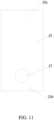
- the embodiment 6 differs from the embodiment 5 only in that the button 27 is used instead of the hook or the loop fastener 26, as shown in FIG. 11 .
- the number of the button 27 used can be selected as needed.
Landscapes
- Life Sciences & Earth Sciences (AREA)
- Environmental Sciences (AREA)
- Zoology (AREA)
- Animal Husbandry (AREA)
- Biodiversity & Conservation Biology (AREA)
- Engineering & Computer Science (AREA)
- Mechanical Engineering (AREA)
- Housing For Livestock And Birds (AREA)
- Purses, Travelling Bags, Baskets, Or Suitcases (AREA)
Abstract
Description
- The present invention relates to the technical field of pet products, and more specifically, to a securing mechanism and a pet loading accessory using the securing mechanism.
- Pet loading accessories, such as pet carriers and pet sofas, are commonly used to load and carry pets. In addition to the loading and carrying function, sometimes it is also necessary to place the pet loading accessories on the seats of vehicles to meet the needs of transporting pets in vehicles.
- When a pet loading accessory is placed on the seat of a vehicle for transportation, it is important to secure the pet loading accessory relative to the seat so that the pet loading accessory will not fall off the seat or move on the seat during the vehicle's movement. To realize the fixation, a strap-like structure is usually used and connected to the seat belt to secure the pet loading accessory. However, the use of a strap-like structure to secure the pet loading accessory does not always provide a reliable securing effect due to the softness and flexibility of the seat belt and the strap-like structure. There are also some mechanical structures that are used for securing the pet loading accessory, such as a rotating arm assembly that is pivotally mounted on an axis to connect and disconnect the pet loading accessory to the seat belt. However, the design of such assembly is complex and expensive due to the presence of several structures and the inconvenience of operation.
- Therefore, it is of great significance to develop a securing mechanism that has a simple structure and is convenient for operation and highly reliable for securing a pet loading accessory.
- In view of the deficiencies in the prior art, the present invention provides a securing mechanism and a pet loading accessory using the securing mechanism.
- On a first aspect, a securing mechanism for a pet loading accessory includes a base, a first blocking portion, and a second blocking portion. The base is provided with a through hole.
- Further, the first blocking portion preferably includes a substantially horizontal segment and a substantially vertical segment. The first end of the substantially horizontal segment of the first blocking portion is fixedly connected to the base, and the second end of the substantially horizontal segment of the first blocking portion is integrally formed with the first end of the substantially vertical segment of the first blocking portion to form a first joint and configure the first blocking portion in an L-shaped bending structure. The second blocking portion includes a substantially horizontal segment and a substantially vertical segment. The first end of the substantially horizontal segment of the second blocking portion is fixedly connected to the base, and the second end of the substantially horizontal segment of the second blocking portion is integrally formed with the first end of the substantially vertical segment of the second blocking portion to form a second joint and configure the second blocking portion in an L-shaped bending structure. The second end of the substantially vertical segment of the first blocking portion and the second end of the substantially vertical segment of the second blocking portion are arranged apart from and opposite to each other in an approaching manner.
- Further, a securing groove is preferably formed between the first blocking portion, the second blocking portion, and the base, and a communication gap communicating with the securing groove is formed between the second end of the substantially vertical segment of the first blocking portion and the second end of the substantially vertical segment of the second blocking portion.
- Further, the length of the substantially vertical segment of the first blocking portion is preferably greater than, equal to, or less than the length of the substantially vertical segment of the second blocking portion.
- Further, the substantially vertical segment of the first blocking portion and the substantially vertical segment of the second blocking portion are preferably both arranged parallel to the base.
- Further, the base is preferably provided with two bolt holes.
- Further, the second end of the substantially vertical segment of the first blocking portion is preferably parallel to the substantially horizontal segment of the first blocking portion, and the second end of the substantially vertical segment of the second blocking portion is parallel to the substantially horizontal segment of the second blocking portion. The surface of the second end of the substantially vertical segment of the first blocking portion is preferably a rounded surface, and the surface of the second end of the substantially vertical segment of the second blocking portion is preferably an inclined surface tilted towards the securing groove. Alternatively, the surface of the second end of the substantially vertical segment of the first blocking portion is preferably an inclined surface tilted towards the securing groove, and the surface of the second end of the substantially vertical segment of the second blocking portion is preferably a rounded surface.
- Further, the second end of the substantially vertical segment of the first blocking portion is preferably parallel or oblique with respect to the substantially horizontal segment of the first blocking portion, and the second end of the substantially vertical segment of the second blocking portion is preferably parallel or oblique with respect to the substantially horizontal segment of the second blocking portion.
- Further, the securing mechanism preferably includes a closed sliding sleeve slidably sleeved on the substantially vertical segment of the first blocking portion, and the closed sliding sleeve is preferably provided with a card slot. The second blocking portion is preferably provided with a card hook, and the card hook is preferably fixedly provided at the second end of the substantially vertical segment of the second blocking portion. When the closed sliding sleeve slides along the substantially vertical segment of the first blocking portion to close the communication gap, the card hook is preferably inserted into and engaged with the card slot.
- On a second aspect, a securing mechanism for a pet loading accessory includes a base, a first blocking portion, and a second blocking portion. The first blocking portion and the second blocking portion are in a staggered configuration.
- Further, the first blocking portion preferably includes a substantially U-shaped segment and a substantially vertical segment. The first end of the substantially U-shaped segment of the first blocking portion is preferably fixedly connected to the base, and the second end of the substantially U-shaped segment of the first blocking portion is preferably integrally formed with the first end of the substantially vertical segment of the first blocking portion to form a first joint and configure the first blocking portion in a hook-like shape. The second blocking portion preferably includes a substantially U-shaped segment and a substantially vertical segment. The first end of the substantially U-shaped segment of the second blocking portion is preferably fixedly connected to the base, and the second end of the substantially U-shaped segment of the second blocking portion is preferably integrally formed with the first end of the substantially vertical segment of the second blocking portion to form a second joint and configure the second blocking portion in a hook-like shape. The second end of the substantially vertical segment of the first blocking portion and the second end of the substantially vertical segment of the second blocking portion are preferably arranged in the staggered configuration in an approaching manner.
- Further, a securing groove is preferably formed between the first blocking portion, the second blocking portion, and the base, and a communication gap communicating with the securing groove is preferably formed between the second end of the substantially vertical segment of the first blocking portion and the second end of the substantially vertical segment of the second blocking portion.
- Further, before the second end of the substantially vertical segment of the first blocking portion and the second end of the substantially vertical segment of the second blocking portion contact, at least one of the second end of the substantially vertical segment of the first blocking portion and the second end of the substantially vertical segment of the second blocking portion preferably turns away to achieve the staggered configuration.
- Further, a protrusion is preferably provided on the substantially vertical segment of the first blocking portion and set inside the securing groove.
- Further, the protrusion preferably is a convex ridge structure protruding from the side facing the base and adjacent to the second end of the second blocking portion.
- On a third aspect, a securing mechanism for a pet loading accessory includes a body. The body includes a fixing end and a movable end, the fixing end is fixedly connected to the pet loading accessory, and the movable end is detachably connected to the pet loading accessory. The body is preferably made of a flexible and non-elastic material. The use of flexible and non-elastic material can reduce the relative movement between the securing mechanism and the safety belt of a vehicle during use and enhance the securing effect of the securing mechanism on the safety belt.
- Further, the fixing end is preferably fixedly connected to the pet loading accessory by an adhesive, a suture, or the like. Alternatively, the fixing end is preferably integrally formed with pet loading accessory. The movable end is preferably detachably connected to the pet loading accessory by a hook or a loop fastener, a button, or the like.
- On a fourth aspect, the present invention provides a pet loading accessory using any of the above securing mechanisms.
- Compared with the prior art, the present invention has the following advantages:
- 1. The securing mechanism provided by the present invention preferably allows the easy access of the safety belt of a vehicle into its accommodating groove/space through a communication gap or a detachable element such as a hook or a loop fastener or a button, thus reducing manual operation and increasing convenience.
- 2. The base of the securing mechanism provided by the present invention is preferably designed with a through hole, which facilitates the demolding of the securing mechanism from a molding die when the securing mechanism is an integrally molded structure and also saves injection molding materials.
- 3. The securing mechanism provided by the present invention preferably has two blocking portions configured in an L-shaped bending structure or a hook-like structure adjacent and opposite to each other, which form a groove with the base to receive the safety belt of a vehicle. The length of the two blocking portions and the width of the safety belt can be adjusted to ensure the part of the safety belt inside the groove not to escape from the groove accidentally, thus achieving a highly reliable securing effect of the securing mechanism on the pet loading accessory.
- 4. The two blocking portions of the securing mechanism provided by the present invention are preferably additionally provided with a card hook and a closed sliding sleeve with a card slot, when in use, the closed sliding sleeve slides to enable the card slot to be engaged with the card hook, such that the communication gap left between the two blocking portions are completely closed and the part of the safety belt inside the groove can never slip out, further enhancing securing effect of the securing mechanism on the pet loading accessory.
- 5. One blocking portion of the securing mechanism provided by the present invention is preferably additionally provided with a protrusion which can further prevent the part of the safety belt inside the groove from slipping out of the groove, thus improving the securing effect of the securing mechanism on the pet loading accessory.
- 6. The two blocking portions of the securing mechanism preferably provided by the present invention can preferably be arranged in a staggered configuration with the tail ends thereof staggered, which is also conducive to preventing the part of the safety belt inside the groove from slipping out of the groove.
- 7. The use of flexible and non-elastic material to fabricate the securing mechanism can preferably reduce the relative movement between the securing mechanism and the safety belt when the two cooperate to secure the pet loading accessory, thus improving the securing effect of the securing mechanism on the pet loading accessory.
-
-
FIG. 1 is a schematic diagram showing the pet loading accessory according toembodiment 1 of the present invention when being placed and fixed on a vehicle seat. -
FIG.2 is a schematic diagram of the securing mechanism shown inFIG. 1 . -
FIG.3 is a semi-sectional schematic diagram of the securing mechanism shown inFIG. 2 . -
FIG.4 is a schematic diagram of the securing mechanism according toembodiment 2 of the present invention. -
FIG. 5 is a schematic diagram of the securing mechanism according toembodiment 3 of the present invention. -
FIG.6 is an enlarged view showing the Part A inFIG. 5 . -
FIG.7 is a schematic diagram of the securing mechanism according toembodiment 4 of the present invention. -
FIG.8 is a side view of the securing mechanism shown inFIG. 7 . -
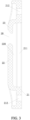
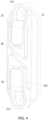
FIG. 9 is a schematic diagram of the securing mechanism according toembodiment 5 of the present invention. -
FIG. 10 is a side view of the securing mechanism shown inFIG. 9 when being assembled on a pet loading accessory. -
FIG. 11 is a schematic diagram of the securing mechanism according toembodiment 6 of the present invention. - Reference numbers in the figures:
- 1. loading body, 2. securing mechanism, 3. vehicle seat, 4. safety belt, 5. safety belt buckle, 6. webbing structure;
- 20. communication gap;
- 21. base, 211. through hole, 212. bolt hole;
- 22. first blocking portion, 220. securing groove, 221. substantially horizontal segment, 222. substantially vertical segment, 223. protrusion, 22a. front end, 22b. joint, 22c. rear end;
- 23. second blocking portion, 231. substantially horizontal segment, 232. substantially vertical segment, 233. card hook, 23a. front end, 23b. joint, 23c. rear end;
- 24. closed sliding sleeve, 241 card slot;
- 25. body, 25a. fixing end, 25b. movable end;
- 26. hook or loop fastener;
- 27. button.
- Specific embodiments of the present invention will be described with reference to the drawings hereinafter.
- Referring to
FIG. 1 , a pet loading accessory includes theloading body 1 and thesecuring mechanism 2. Thesecuring mechanism 2 is arranged on the outer edge of theloading body 1 and is used for securing the pet loading accessory with a strap-like body used for securing. Thesecuring mechanism 2 can be placed at any position of theloading body 1 as required. Thesecuring mechanism 2 can be a fitting attached to theloading body 1 or a structure integrally formed with theloading body 1. - Specifically, the types of the pet loading accessory include a pet sofa, a pet carrier, a pet transport box with vehicle functions, etc. In the present embodiment, a pet sofa that can be carried in a vehicle is used as an example for illustration. In
FIG. 1 , the pet loading accessory is placed on thevehicle seat 3. The three-point safety belt 4 of thevehicle seat 3 is inserted into thesafety belt buckle 5 and is in a roughly horizontal position, which is the strap-like body mentioned above. Thesecuring mechanism 2 is used to secure the pet loading accessory by cooperating with the roughly horizontal section of the three-point safety belt 4, so that theloading body 1 is secured by the retraction force of the three-point safety belt 4 during normal use and by the cooperation of thesecuring mechanism 2 and the three-point safety belt 4 being locked in the case of an emergency. When the pet loading accessory is in the state of being placed on thevehicle seat 3, the side of the peripheral edge of the pet loading accessory facing the direction of vehicle travel is defined as the front side of theloading body 1. To further improve the cooperative effect between the securingmechanism 2 and the three-point safety belt 4, two ormore securing mechanisms 2 can be used. In the present embodiment, two securingmechanisms 2 are used and respectively arranged on the front side of theloading body 1, and the two securingmechanisms 2 are set at approximately the same height. Thesecuring mechanism 2 is an independently manufactured element, which is locked on the front side of theloading body 1 by screws or similar fastening members. In the present embodiment, the pet loading accessory is also secured by thewebbing structure 6 hung on the headrest of thevehicle seat 3. - Referring to
FIG. 2 to FIG. 3 , thesecuring mechanism 2 includes thebase 21, the first blockingportion 22, and thesecond blocking portion 23. Thefirst blocking portion 22 and thesecond blocking portion 23 are configured in an L-shaped bending structure. Thefirst blocking portion 22 has the substantiallyhorizontal segment 221 and the substantiallyvertical segment 222 that are connected to configure the first blockingportion 22 in the L shape. Thefront end 22a of the first blockingportion 22 is fixedly arranged on thebase 21, the substantiallyhorizontal segment 221 is formed by extending outwardly from thefront end 22a to the joint 22b of the first blockingportion 22, and the substantiallyvertical segment 222 is formed by extending from the joint 22b to therear end 22c of the first blockingportion 22. The substantiallyvertical segment 222 is parallel to and spaced apart from thebase 21, and the parallel arrangement can be roughly parallel or slightly inclined relative to the base21. Thesecond blocking portion 23 has the substantiallyhorizontal segment 231 and the substantiallyvertical segment 232 that are connected to configure the first blockingportion 23 in an L-shaped bending structure. Thefront end 23a of thesecond blocking portion 23 is fixedly arranged on thebase 21, the substantiallyhorizontal segment 231 is formed by extending outwardly from thefront end 23a to the joint 23b of thesecond blocking portion 23, and the substantiallyvertical segment 232 is formed by extending from the joint 23b to therear end 23c of thesecond blocking portion 23. The substantiallyvertical segment 232 is parallel to and spaced apart from thebase 21, and the parallel arrangement can be roughly parallel or slightly inclined relative to the base21. Therear end 22c of the first blockingportion 22 and therear end 23c of thesecond blocking portion 23 are arranged apart from and opposite to each other in an approaching manner. The securinggroove 220 is formed between the bending structure of the first blockingportion 22, the bending structure of thesecond blocking portion 23, and thebase 21. Thecommunication gap 20 communicating with the securinggroove 220 is formed between therear end 22c of the first blockingportion 22 and therear end 23c of thesecond blocking portion 23. - The length of the substantially
vertical segment 222 of the first blockingportion 22 and the length of the substantiallyvertical segment 232 of thesecond blocking portion 23 can be adjusted as needed. The length of the substantiallyvertical segment 222 can be greater than, equal to, or less than that of the substantiallyvertical segment 232. In the present embodiment, the length of the substantiallyvertical segment 222 is greater than that of the substantiallyvertical segment 232. - Preferably, the middle and lower part of the securing
groove 220, which is the space formed between the bending structure of the first blockingportion 22 and thebase 21, is mainly used to accommodate the roughly horizontal section of the three-point seat belt 4. Thesecond blocking portion 23 mainly cooperates with the first blockingportion 22 to prevent the roughly horizontal section of the three-point seat belt 4 from slipping out from the top of the first blockingportion 22. Therefore, the length of the substantiallyvertical segment 222 of the first blockingportion 22 is set to be greater than that of the substantiallyvertical segment 232 of thesecond blocking portion 23. - The
first blocking portion 22 and thesecond blocking portion 23 are both in a bent plate structure. Thebase 21 is in a strip plate structure. The substantiallyvertical segment 222 and the substantiallyvertical segment 232 are both arranged parallel to thebase 21. Thebase 21, the first blockingportion 22, and thesecond blocking portion 23 are integrally molded. Thebase 21 is provided with the throughhole 211 and two bolt holes 212. The shape of the throughhole 211 and the bolt holes 212 can be selected as needed. In the present embodiment, the throughhole 211 is square and the bolt holes are circular. The square throughhole 211 and the bolt holes 212 penetrate the thickness direction of thebase 21, and the square throughhole 211 is located in the middle of thebase 21 and is connected to thefront end 22a of the first blockingportion 22 and thefront end 23a of thesecond blocking portion 23. The square throughhole 211 is connected to the securinggroove 220. The twobolt holes 212 are located at two ends of thebase 21, respectively. Since thesecuring mechanism 2 is an integrally molded structure, the setting of the square throughhole 211 can facilitate the demolding of thesecuring mechanism 2 from a molding die and also save injection molding materials. - Referring to
FIG. 1 to FIG. 3 , thesecuring mechanism 2 can be secured in place by inserting and fastening bolts into the bolt holes 212. Specifically, since the securinggroove 220 is used to hold and constrain the roughly horizontal section of the three-point safety belt 4 to secure the pet loading accessory, it is preferred that the first blockingportion 22 is located below thesecond blocking portion 23. The substantiallyvertical segment 222 of the first blockingportion 22 is longer that the substantiallyvertical segment 232 of thesecond blocking portion 23, which allows over half of the securinggroove 220 to be used to safely accommodate the roughly horizontal section of the three-point safety belt 4. Thesecuring mechanism 2 is secured by bolts with the back of the base 21 in contact with theloading body 1 of the pet loading accessory. To facilitate the entry of the roughly horizontal section of the three-point safety belt 4 into the securinggroove 220 through thecommunication gap 20, it is preferred that the surface of therear end 22c of the first blockingportion 22 and the surface of therear end 23c of thesecond blocking portion 23 are designed as rounded surfaces or inclined surfaces tilted towards the location of the securinggroove 220. In the present embodiment, as shown inFIG. 2 andFIG. 3 , the surface of therear end 22c of the first blockingportion 22 is designed as a rounded surface and the surface of therear end 23c of thesecond blocking portion 23 is designed as an inclined surface. - To prevent the roughly horizontal section of the three-
point safety belt 4 from slipping out through thecommunication gap 20 during use and improve the stability of the fixation of the pet loading accessory, the width of the roughly horizontal section of the three-point safety belt 4 is greater than the distance between the joint 22b of the first blockingportion 22 and the lowest point of therear end 23c of thesecond blocking portion 23, but less than the distance between the joint 22b of the first blockingportion 22 and the joint 23b of thesecond blocking portion 23. Preferably, the width of the roughly horizontal section of the three-point safety belt 4 is at least 10 mm greater than the distance between the joint 22b of the first blockingportion 22 and the lowest point of therear end 23b of thesecond blocking portion 23. Since, in the present embodiment, the projection of thecommunication gap 20 on thebase 21 is roughly perpendicular to the length direction of thebase 21, that is, therear end 22c of the first blockingportion 22 and therear end 23c of thesecond blocking portion 23 are both perpendicular to the length direction of thebase 21, the distance between the joint 22b of the first blockingportion 22 and the lowest point of therear end 23c of thesecond blocking portion 23 actually refers to the distance between the joint 22b of the first blockingportion 22 and therear end 23c of thesecond blocking portion 23. - Referring to
FIG. 4 , the main differences betweenembodiment 2 andembodiment 1 are as follows: - 1. In
embodiment 1, the length of the substantiallyvertical segment 222 of the first blockingportion 22 is greater than the length of the substantiallyvertical segment 232 of thesecond blocking portion 23, while in the present embodiment, the length of the substantiallyvertical segment 222 of the first blockingportion 22 is equal to the length of the substantiallyvertical segment 232 of thesecond blocking portion 23.
The length of the substantiallyvertical segment 222 of the first blockingportion 22 is equal to the length of the substantiallyvertical segment 232 of thesecond blocking portion 23, and the width of the roughly horizontal section of the three-point safety belt 4 itself is greater than the distance between the joint 22b of the first blockingportion 22 and the lowest point of therear end 23c of thesecond blocking portion 23, as a result, nearly half of the roughly horizontal section of the three-point safety belt 4 enters the cavity formed by the bending structure of thesecond blocking portion 23 and thebase 21. In fact, the expression of the first blockingportion 22 and thesecond blocking portion 23 is for the ease of differentiation, and they can be configured in the same structure or different structures. Moreover, those skilled in the art can easily set up alternative ways, such as the length of the substantiallyvertical segment 222 of the first blockingportion 22 being smaller than the length of the substantiallyvertical segment 232 of thesecond blocking portion 23. - 2. In
embodiment 1, therear end 22c of the first blockingportion 22 and therear end 23c of thesecond blocking portion 23 are roughly perpendicular to the vertical direction, i.e., the projection of thecommunication gap 20 on thebase 21 is roughly perpendicular to the length direction of thebase 21, while in the present embodiment, therear end 22c of the first blockingportion 22 and therear end 23c of thesecond blocking portion 23 are set to be relatively oblique with respect to the vertical direction. - Referring to
FIG. 5 to FIG. 6 , thesecuring mechanism 2 for a pet loading accessory which is identical to the pet loading accessory inembodiment 1 is provided. Thesecuring mechanism 2 includes thebase 21, the first blockingportion 22, thesecond blocking portion 23, and the closed slidingsleeve 24. Thefirst blocking portion 22 and thesecond blocking portion 23 both have a bending plate-like structure extending along an L shape, while thebase 21 has a strip-shaped plate-like structure. Thesecuring mechanism 2 is integrally formed by an injection molding. Thebase 21 and the first blockingportion 22 are identical to thebase 21 and the first blockingportion 22 inembodiment 1, and thesecond blocking portion 23 differs from thesecond blocking portion 23 inembodiment 1 only in that thecard hook 233 is further provided on thesecond blocking portion 23. The closed slidingsleeve 24 is slidably sleeved on the outside of the first blockingportion 22. Alternatively, the card hook can be provided on the closed sliding sleeve and the card slot can be provided on the second blocking portion. The closed slidingsleeve 24 is used to close thecommunication gap 20. Since the length of the substantiallyvertical segment 222 of the first blockingportion 22 is greater than that of the substantiallyvertical segment 232 of thesecond blocking portion 23, the closed slidingsleeve 24 is preferably slidably sleeved on the substantiallyvertical segment 222 of the first blockingportion 22. In the present embodiment, since thecommunication gap 20 can be closed by the closed slidingsleeve 24, when thesecuring mechanism 2 is assembled to the outer edge of theloading body 1, it can be applied well regardless of whether the first blockingportion 22 is above or below thesecond blocking portion 23. When the first blockingportion 22 is above thesecond blocking portion 23, the closed slidingsleeve 24 can maintain the closure of thecommunication gap 20 due to gravity, so no other structure is needed between the closed slidingsleeve 24 and therear end 23c of thesecond blocking portion 23. - Referring to
FIG. 5 to FIG. 6 , the present embodiment further describes the process closing thecommunication gap 20 when thesecuring mechanism 2 is assembled to the front side of theloading body 1 with the first blockingportion 22 arranged below thesecond blocking portion 23. Thesecond blocking portion 23 is provided with thecard hook 233, which is fixedly arranged at therear end 23c of thesecond blocking portion 23. The closed slidingsleeve 24 is provided with thecard slot 241, which is matched with thecard hook 233. When the closed slidingsleeve 24 slides along the substantiallyvertical segment 222 of the first blockingportion 22 to close thecommunication gap 20, thecard hook 233 is inserted into and engaged with thecard slot 241 to avoid the closed slidingsleeve 24 from sliding off due to gravity. - Referring to
FIG. 7 to FIG. 8 , thesecuring mechanism 2 for a pet loading accessory which is identical to the pet loading accessory inembodiment 1 is provided. Thesecuring mechanism 2 includes thebase 21, the first blockingportion 22, and thesecond blocking portion 23. Thefirst blocking portion 22 and thesecond blocking portion 23 have a bending plate-like structure overall presented in a hook-like shape. Thebase 21 has a strip-shaped plate-like structure. Thesecuring mechanism 2 is integrally formed by an injection molding. Thefirst blocking portion 22 has the substantiallyU-shaped segment 221 and the substantiallyvertical segment 222 that are connected to configure the first blockingportion 22 in the hook-like shape. Thefront end 22a of the first blockingportion 22 is fixedly arranged on thebase 21, the substantiallyU-shaped segment 221 is formed by extending outwardly from thefront end 22a to the joint 22b of the first blockingportion 22, and the substantiallyvertical segment 222 is formed by extending from the joint 22b to therear end 22c of the first blockingportion 22. The substantiallyvertical segment 222 is arranged spaced apart from thebase 21. Thesecond blocking portion 23 has the substantiallyU-shaped segment 231 and the substantiallyvertical segment 232 that are connected to configure the first blockingportion 23 in the hook-like shape. Thefront end 23a of thesecond blocking portion 23 is fixedly arranged on thebase 21, the substantiallyU-shaped segment 231 is formed by extending outwardly from thefront end 23a to the joint 23b of thesecond blocking portion 23, and the substantiallyvertical segment 232 is formed by extending from the joint 23b to therear end 23c of thesecond blocking portion 23. The substantiallyvertical segment 232 is arranged spaced apart from thebase 21. Therear end 22c of the first blockingportion 22 and therear end 23c of thesecond blocking portion 23 are arranged in an approaching and staggered manner. Thefront end 22a of the first blockingportion 22 and thefront end 23a of thesecond blocking portion 23 are located on the same side of thebase 21 and are respectively adjacent to two ends along the length direction of thebase 21. The securinggroove 220 is formed between the first blockingportion 22, thesecond blocking portion 23, and thebase 21. - Referring to
FIG. 7 to FIG. 8 , the substantiallyU-shaped segment 221 of the first blockingportion 22 and the substantiallyU-shaped segment 231 of thesecond blocking portion 23 are roughly parallel to each other, and the distance between the joint 22b and thefront end 22a of the first blockingportion 22 is basically equal to the distance between the joint 23b and thefront end 23a of thesecond blocking portion 23. Therear end 22c of the first blockingportion 22 and therear end 23c of thesecond blocking portion 23 approach towards each other along the direction roughly parallel to the length direction of thebase 21. Before therear end 22c of the first blockingportion 22 and therear end 23c of thesecond blocking portion 23 contact, at least one of therear end 22c and therear end 23c turns away to achieve the staggered configuration. Thecommunication gap 20 is formed between therear end 22c of the first blockingportion 22 and therear end 23c of thesecond blocking portion 23 and communicates with the securinggroove 220. Thecommunication gap 20 can be formed by staggering therear end 22c of the first blockingportion 22 and therear end 23c of thesecond blocking portion 23 with therear end 22c closer to the base 21 than therear end 23c or therear end 23c closer to the base 21 than therear end 22c. - Referring to
FIG. 7 to FIG. 8 , in the present embodiment, before therear end 22c of the first blockingportion 22 and therear end 23c of thesecond blocking portion 23 contact, therear end 22c turns away from thebase 21. The length of the substantiallyvertical segment 222 of the first blockingportion 22 is greater than the length of the substantiallyvertical segment 232 of thesecond blocking portion 23. The staggered structure facilitates the entry of the roughly horizontal section of the three-point safety belt 4 into the securinggroove 220 and reduces the chance of the roughly horizontal section of the three-point safety belt 4 accidentally slipping out of the securinggroove 220. Furthermore, theprotrusion 223 is additionally provided on the substantiallyvertical segment 222 of the first blockingportion 22 and set inside the securinggroove 220. Theprotrusion 223 is a convex ridge structure protruding from the side facing the position where thebase 21 is located and adjacent to therear end 23c of thesecond blocking portion 23. Theprotrusion 223 helps to enhance the constraint ability of the securinggroove 220 on the roughly horizontal section of the three-point safety belt 4, thereby further reducing the chance of the roughly horizontal section of the three-point safety belt 4 accidentally slipping out of the securinggroove 220. In addition, since therear end 22c of the first blockingportion 22 and therear end 23c of thesecond blocking portion 23 are staggered during the injection molding process of thesecuring mechanism 2 in the present embodiment, the square throughhole 211 inembodiment 1 is not necessary and can be omitted accordingly. - Referring to
FIG. 9 and FIG. 10 , the present embodiment provides the securing mechanism for a pet loading accessory which is identical to the pet loading accessory inembodiment 1 is provided. Thesecuring mechanism 2 includes thebody 25 having the fixingend 25a and themovable end 25b. The fixingend 25a is fixedly connected to the pet loading accessory, and themovable end 25b is detachably connected to the pet loading accessory. Thebody 25 of thesecuring mechanism 2 is made of a flexible and non-elastic material. The use of flexible and non-elastic material can reduce the relative movement between the securingmechanism 2 and thesafety belt 4 during use and enhance the securing effect of thesecuring mechanism 2 on the roughly horizontal section of the three-point safety belt 4. The fixingend 25a is fixedly connected to the pet loading accessory by an adhesive, a suture, or the like. Alternatively, the fixingend 25a is integrally formed with pet loading accessory. Themovable end 25b is detachably connected to the pet loading accessory by the hook or theloop fastener 26. In this configuration, the space enclosed by thebody 25 of thesecuring mechanism 2 and the pet loading accessory can be used to accommodate the roughly horizontal section of the three-point safety belt 4 for securing the pet loading accessory and during use thesecuring mechanism 2 will not prone to deforming due to non-elasticity. Themovable end 25b is detachably connected to the pet loading accessory so that when the roughly horizontal section of the three-point safety belt 4 needs to be inserted into or removed from the space, themovable end 25b can be separated from the pet loading accessory by pulling the hook or theloop fastener 26, thus facilitating the operation. - The
embodiment 6 differs from theembodiment 5 only in that thebutton 27 is used instead of the hook or theloop fastener 26, as shown inFIG. 11 . The number of thebutton 27 used can be selected as needed.
Claims (15)
- A securing mechanism for a pet loading accessory, comprising:a base,a first blocking portion, anda second blocking portion;wherein the base is provided with a through hole.
- The securing mechanism for the pet loading accessory according to claim 1, whereinthe first blocking portion comprises a substantially horizontal segment and a substantially vertical segment, a first end of the substantially horizontal segment of the first blocking portion is fixedly connected to the base, and a second end of the substantially horizontal segment of the first blocking portion is integrally formed with a first end of the substantially vertical segment of the first blocking portion to form a first joint and configure the first blocking portion in an L-shaped bending structure;the second blocking portion comprises a substantially horizontal segment and a substantially vertical segment, a first end of the substantially horizontal segment of the second blocking portion is fixedly connected to the base, and a second end of the substantially horizontal segment of the second blocking portion is integrally formed with a first end of the substantially vertical segment of the second blocking portion to form a second joint and configure the second blocking portion in an L-shaped bending structure; anda second end of the substantially vertical segment of the first blocking portion and a second end of the substantially vertical segment of the second blocking portion are arranged apart from and opposite to each other in an approaching manner.
- The securing mechanism for the pet loading accessory according to claim 2, whereina securing groove is formed between the first blocking portion, the second blocking portion, and the base; anda communication gap communicating with the securing groove is formed between the second end of the substantially vertical segment of the first blocking portion and the second end of the substantially vertical segment of the second blocking portion.
- The securing mechanism for the pet loading accessory according to claim 2 or 3, wherein a length of the substantially vertical segment of the first blocking portion is greater than a length of the substantially vertical segment of the second blocking portion.
- The securing mechanism for the pet loading accessory according to any one of claims 2 to 4, wherein the substantially vertical segment of the first blocking portion and the substantially vertical segment of the second blocking portion are both arranged parallel to the base.
- The securing mechanism for the pet loading accessory according to any one of the preceding claims, wherein the base is further provided with two bolt holes.
- The securing mechanism for the pet loading accessory according to claim 3, wherein the second end of the substantially vertical segment of the first blocking portion is parallel to the substantially horizontal segment of the first blocking portion, and the second end of the substantially vertical segment of the second blocking portion is parallel to the substantially horizontal segment of the second blocking portion; and
a surface of the second end of the substantially vertical segment of the first blocking portion is a rounded surface, and a surface of the second end of the substantially vertical segment of the second blocking portion is an inclined surface tilted towards the securing groove. - The securing mechanism for the pet loading accessory according to claim 2, whereina length of the substantially vertical segment of the first blocking portion is equal to a length of the substantially vertical segment of the second blocking portion; andthe second end of the substantially vertical segment of the first blocking portion is oblique with respect to the substantially horizontal segment of the first blocking portion, and the second end of the substantially vertical segment of the second blocking portion is oblique with respect to the substantially horizontal segment of the second blocking portion.
- The securing mechanism for the pet loading accessory according to claim 3, whereinthe securing mechanism further comprises a closed sliding sleeve slidably sleeved on the substantially vertical segment of the first blocking portion; andthe second blocking portion is provided with a card hook.
- The securing mechanism for the pet loading accessory according to claim 9, wherein the closed sliding sleeve is provided with a card slot;the card hook is fixedly provided at the second end of the substantially vertical segment of the second blocking portion; andwhen the closed sliding sleeve slides along the substantially vertical segment of the first blocking portion to close the communication gap, the card hook is inserted into and engaged with the card slot.
- A securing mechanism for a pet loading accessory, comprising a body, preferably made of flexible material and non-elastic material; wherein the body comprises a fixing end and a movable end, wherein the fixing end is fixedly connected to the pet loading accessory, and the movable end is detachably connected to the pet loading accessory.
- The securing mechanism for the pet loading accessory according to claim 11, wherein the fixing end is fixedly connected to the pet loading accessory by an adhesive or a suture, or the fixing end is integrally formed with pet loading accessory.
- The securing mechanism for the pet loading accessory according to claim 11 or 12,wherein the movable end is detachably connected to the pet loading accessory by a hook or a loop fastener.
- The securing mechanism for the pet loading accessory according to claim 11 or 12, wherein the movable end is detachably connected to the pet loading accessory by a button.
- The securing mechanism for the pet loading accessory according to any one of claims 11 to 14, further comprising means for connecting the movable end to the pet loading accessory.
Applications Claiming Priority (1)
| Application Number | Priority Date | Filing Date | Title |
|---|---|---|---|
| CN202320656890.6U CN219514882U (en) | 2022-10-12 | 2023-03-29 | Connecting mechanism of pet loading tool and pet loading tool |
Publications (1)
| Publication Number | Publication Date |
|---|---|
| EP4437840A1 true EP4437840A1 (en) | 2024-10-02 |
Family
ID=90105349
Family Applications (1)
| Application Number | Title | Priority Date | Filing Date |
|---|---|---|---|
| EP24160335.6A Pending EP4437840A1 (en) | 2023-03-29 | 2024-02-28 | Securing mechanism and pet loading accessory using the securing mechanism |
Country Status (4)
| Country | Link |
|---|---|
| US (1) | US12274237B2 (en) |
| EP (1) | EP4437840A1 (en) |
| JP (1) | JP7732654B2 (en) |
| AU (1) | AU2024201906A1 (en) |
Families Citing this family (2)
| Publication number | Priority date | Publication date | Assignee | Title |
|---|---|---|---|---|
| USD1091373S1 (en) * | 2023-03-29 | 2025-09-02 | Xiamen Sunnypet Products Co., Ltd | Securing buckle |
| USD1063237S1 (en) * | 2024-08-30 | 2025-02-18 | Haifeng Ximei Hardware Co., Ltd | Dog car seat |
Citations (5)
| Publication number | Priority date | Publication date | Assignee | Title |
|---|---|---|---|---|
| US20160057968A1 (en) * | 2014-08-26 | 2016-03-03 | Naked Eye Images, Inc. | Restrainable Pet Transporter |
| USD804738S1 (en) * | 2016-12-05 | 2017-12-05 | Oxgord Incorporated | Pet carrier |
| US9849838B1 (en) * | 2014-03-11 | 2017-12-26 | Richard A. Siciliano | Material transport cage and methods of using the same |
| US10772288B1 (en) * | 2018-06-14 | 2020-09-15 | Doskocil Manufacturing Company, Inc | Pet carrier car seat |
| US20210259199A1 (en) * | 2020-02-25 | 2021-08-26 | Doskocil Manufacturing Company, Inc. | Pet carrier |
Family Cites Families (13)
| Publication number | Priority date | Publication date | Assignee | Title |
|---|---|---|---|---|
| JP2002159239A (en) * | 2000-11-28 | 2002-06-04 | Iris Ohyama Inc | Pet Car Case |
| US6669302B2 (en) * | 2001-05-08 | 2003-12-30 | Graco Children's Products Inc. | Seat belt position adjusting arrangement for a vehicle seat |
| JP2005348700A (en) | 2004-06-14 | 2005-12-22 | Ck Hanbai Kk | Structure for fixing pet animal-contained box |
| US20100000472A1 (en) | 2008-07-03 | 2010-01-07 | Tibor Siklosi | Seat belt loop system for a pet carrier |
| US7971908B2 (en) * | 2009-05-29 | 2011-07-05 | GM Global Technology Operations LLC | Guide assembly for a safety belt |
| JP5980099B2 (en) * | 2012-11-12 | 2016-08-31 | 株式会社リッチェル | Pet carry |
| CN204020804U (en) | 2014-08-29 | 2014-12-17 | 涂志强 | A kind of safety strap clip |
| US10173634B2 (en) * | 2016-06-23 | 2019-01-08 | Ford Global Technologies, Llc | Seat mounted adjustable seat belt webbing guide |
| US10196033B2 (en) * | 2016-07-18 | 2019-02-05 | Ford Global Technologies, Llc | Seat mounted adjustable seat belt webbing guide |
| CN206284082U (en) | 2016-12-26 | 2017-06-30 | 厦门吉信德宠物用品有限公司 | A kind of vehicle-mounted pet sofa |
| US10589865B2 (en) * | 2018-02-17 | 2020-03-17 | Ami Industries, Inc | Guide-web |
| CN208657611U (en) | 2018-08-08 | 2019-03-29 | 代国庆 | It is securable to the Pet aviation case of automotive seat |
| GB2594724B (en) * | 2020-05-05 | 2022-10-12 | Jaguar Land Rover Ltd | Apparatus for retaining a seat belt |
-
2023
- 2023-06-12 US US18/208,396 patent/US12274237B2/en active Active
-
2024
- 2024-02-28 EP EP24160335.6A patent/EP4437840A1/en active Pending
- 2024-03-25 AU AU2024201906A patent/AU2024201906A1/en active Pending
- 2024-03-27 JP JP2024050633A patent/JP7732654B2/en active Active
Patent Citations (5)
| Publication number | Priority date | Publication date | Assignee | Title |
|---|---|---|---|---|
| US9849838B1 (en) * | 2014-03-11 | 2017-12-26 | Richard A. Siciliano | Material transport cage and methods of using the same |
| US20160057968A1 (en) * | 2014-08-26 | 2016-03-03 | Naked Eye Images, Inc. | Restrainable Pet Transporter |
| USD804738S1 (en) * | 2016-12-05 | 2017-12-05 | Oxgord Incorporated | Pet carrier |
| US10772288B1 (en) * | 2018-06-14 | 2020-09-15 | Doskocil Manufacturing Company, Inc | Pet carrier car seat |
| US20210259199A1 (en) * | 2020-02-25 | 2021-08-26 | Doskocil Manufacturing Company, Inc. | Pet carrier |
Also Published As
| Publication number | Publication date |
|---|---|
| AU2024201906A1 (en) | 2024-10-17 |
| JP7732654B2 (en) | 2025-09-02 |
| US12274237B2 (en) | 2025-04-15 |
| JP2024144325A (en) | 2024-10-11 |
| US20240324548A1 (en) | 2024-10-03 |
Similar Documents
| Publication | Publication Date | Title |
|---|---|---|
| EP4437840A1 (en) | Securing mechanism and pet loading accessory using the securing mechanism | |
| US5011349A (en) | Tailgate mounted cargo retaining device | |
| US7040694B2 (en) | Infant car seat and stroller system | |
| US5050274A (en) | Free running and cinching latch plate | |
| US10576850B2 (en) | Child safety seat | |
| EP3486126B1 (en) | Webbing adjustment device | |
| US8038214B2 (en) | Harness system for juvenile vehicle seat | |
| CN212243177U (en) | Hook ring | |
| CN110077294B (en) | Child safety seat | |
| EP1154711B1 (en) | Swivel clip for releasably securing personal articles | |
| JP2003033209A (en) | buckle | |
| US20030140461A1 (en) | Buckle | |
| US4935994A (en) | Free running cinching seat belt latchplate | |
| KR100361265B1 (en) | Zipper pull of slider for slide fastener | |
| US4150843A (en) | Seat belt securing device | |
| CN219514882U (en) | Connecting mechanism of pet loading tool and pet loading tool | |
| US4751772A (en) | Two part waist buckle with snap-fitting retention feature | |
| US20230256873A1 (en) | Child Safety Seat and Safety Belt Limiting Device | |
| US5333935A (en) | Seat belt system providing increased occupant mobility | |
| JPH08154722A (en) | Backpack bag | |
| CN223626647U (en) | Load-bearing device | |
| US4142737A (en) | Seat belt securing device | |
| CN220157769U (en) | Schoolbag convenient to store transportation | |
| AU2024209286A1 (en) | Storage structure and child safety seat | |
| GB2354214A (en) | Luggage retention assembly |
Legal Events
| Date | Code | Title | Description |
|---|---|---|---|
| PUAI | Public reference made under article 153(3) epc to a published international application that has entered the european phase |
Free format text: ORIGINAL CODE: 0009012 |
|
| STAA | Information on the status of an ep patent application or granted ep patent |
Free format text: STATUS: THE APPLICATION HAS BEEN PUBLISHED |
|
| AK | Designated contracting states |
Kind code of ref document: A1 Designated state(s): AL AT BE BG CH CY CZ DE DK EE ES FI FR GB GR HR HU IE IS IT LI LT LU LV MC ME MK MT NL NO PL PT RO RS SE SI SK SM TR |
|
| STAA | Information on the status of an ep patent application or granted ep patent |
Free format text: STATUS: REQUEST FOR EXAMINATION WAS MADE |
|
| 17P | Request for examination filed |
Effective date: 20250320 |
|
| STAA | Information on the status of an ep patent application or granted ep patent |
Free format text: STATUS: EXAMINATION IS IN PROGRESS |
|
| 17Q | First examination report despatched |
Effective date: 20250623 |