EP4436157A1 - Image reading device - Google Patents
Image reading device Download PDFInfo
- Publication number
- EP4436157A1 EP4436157A1 EP24164859.1A EP24164859A EP4436157A1 EP 4436157 A1 EP4436157 A1 EP 4436157A1 EP 24164859 A EP24164859 A EP 24164859A EP 4436157 A1 EP4436157 A1 EP 4436157A1
- Authority
- EP
- European Patent Office
- Prior art keywords
- section
- light transmitting
- rotation
- transmitting member
- rotation member
- Prior art date
- Legal status (The legal status is an assumption and is not a legal conclusion. Google has not performed a legal analysis and makes no representation as to the accuracy of the status listed.)
- Pending
Links
Images





Classifications
-
- H—ELECTRICITY
- H04—ELECTRIC COMMUNICATION TECHNIQUE
- H04N—PICTORIAL COMMUNICATION, e.g. TELEVISION
- H04N1/00—Scanning, transmission or reproduction of documents or the like, e.g. facsimile transmission; Details thereof
- H04N1/00976—Arrangements for regulating environment, e.g. removing static electricity
- H04N1/00978—Temperature control
- H04N1/00981—Temperature control by forced convection, e.g. using fans
-
- H—ELECTRICITY
- H04—ELECTRIC COMMUNICATION TECHNIQUE
- H04N—PICTORIAL COMMUNICATION, e.g. TELEVISION
- H04N1/00—Scanning, transmission or reproduction of documents or the like, e.g. facsimile transmission; Details thereof
- H04N1/00909—Cleaning arrangements or preventing or counter-acting contamination from dust or the like
-
- H—ELECTRICITY
- H04—ELECTRIC COMMUNICATION TECHNIQUE
- H04N—PICTORIAL COMMUNICATION, e.g. TELEVISION
- H04N1/00—Scanning, transmission or reproduction of documents or the like, e.g. facsimile transmission; Details thereof
- H04N1/00567—Handling of original or reproduction media, e.g. cutting, separating, stacking
- H04N1/0057—Conveying sheets before or after scanning
- H04N1/00572—Conveying sheets before or after scanning with refeeding for double-sided scanning, e.g. using one scanning head for both sides of a sheet
-
- H—ELECTRICITY
- H04—ELECTRIC COMMUNICATION TECHNIQUE
- H04N—PICTORIAL COMMUNICATION, e.g. TELEVISION
- H04N1/00—Scanning, transmission or reproduction of documents or the like, e.g. facsimile transmission; Details thereof
- H04N1/00567—Handling of original or reproduction media, e.g. cutting, separating, stacking
- H04N1/0057—Conveying sheets before or after scanning
- H04N1/00572—Conveying sheets before or after scanning with refeeding for double-sided scanning, e.g. using one scanning head for both sides of a sheet
- H04N1/00575—Inverting the sheet prior to refeeding
- H04N1/00583—Inverting the sheet prior to refeeding by rotating the sheet about an axis lying in its plane
-
- H—ELECTRICITY
- H04—ELECTRIC COMMUNICATION TECHNIQUE
- H04N—PICTORIAL COMMUNICATION, e.g. TELEVISION
- H04N1/00—Scanning, transmission or reproduction of documents or the like, e.g. facsimile transmission; Details thereof
- H04N1/00567—Handling of original or reproduction media, e.g. cutting, separating, stacking
- H04N1/0057—Conveying sheets before or after scanning
- H04N1/00599—Using specific components
- H04N1/00602—Feed rollers
-
- H—ELECTRICITY
- H04—ELECTRIC COMMUNICATION TECHNIQUE
- H04N—PICTORIAL COMMUNICATION, e.g. TELEVISION
- H04N1/00—Scanning, transmission or reproduction of documents or the like, e.g. facsimile transmission; Details thereof
- H04N1/00567—Handling of original or reproduction media, e.g. cutting, separating, stacking
- H04N1/00649—Control or synchronising different handling operations
-
- H—ELECTRICITY
- H04—ELECTRIC COMMUNICATION TECHNIQUE
- H04N—PICTORIAL COMMUNICATION, e.g. TELEVISION
- H04N1/00—Scanning, transmission or reproduction of documents or the like, e.g. facsimile transmission; Details thereof
- H04N1/04—Scanning arrangements, i.e. arrangements for the displacement of active reading or reproducing elements relative to the original or reproducing medium, or vice versa
- H04N1/12—Scanning arrangements, i.e. arrangements for the displacement of active reading or reproducing elements relative to the original or reproducing medium, or vice versa using the sheet-feed movement or the medium-advance or the drum-rotation movement as the slow scanning component, e.g. arrangements for the main-scanning
- H04N1/121—Feeding arrangements
- H04N1/1235—Feeding a sheet past a transparent plate; Details thereof
-
- H—ELECTRICITY
- H04—ELECTRIC COMMUNICATION TECHNIQUE
- H04N—PICTORIAL COMMUNICATION, e.g. TELEVISION
- H04N1/00—Scanning, transmission or reproduction of documents or the like, e.g. facsimile transmission; Details thereof
- H04N1/04—Scanning arrangements, i.e. arrangements for the displacement of active reading or reproducing elements relative to the original or reproducing medium, or vice versa
- H04N1/12—Scanning arrangements, i.e. arrangements for the displacement of active reading or reproducing elements relative to the original or reproducing medium, or vice versa using the sheet-feed movement or the medium-advance or the drum-rotation movement as the slow scanning component, e.g. arrangements for the main-scanning
- H04N1/121—Feeding arrangements
- H04N1/125—Feeding arrangements the sheet feeding apparatus serving an auxiliary function, e.g. as a white reference
-
- H—ELECTRICITY
- H04—ELECTRIC COMMUNICATION TECHNIQUE
- H04N—PICTORIAL COMMUNICATION, e.g. TELEVISION
- H04N1/00—Scanning, transmission or reproduction of documents or the like, e.g. facsimile transmission; Details thereof
- H04N1/04—Scanning arrangements, i.e. arrangements for the displacement of active reading or reproducing elements relative to the original or reproducing medium, or vice versa
- H04N1/19—Scanning arrangements, i.e. arrangements for the displacement of active reading or reproducing elements relative to the original or reproducing medium, or vice versa using multi-element arrays
- H04N1/191—Scanning arrangements, i.e. arrangements for the displacement of active reading or reproducing elements relative to the original or reproducing medium, or vice versa using multi-element arrays the array comprising a one-dimensional [1D] array
- H04N1/192—Simultaneously or substantially simultaneously scanning picture elements on one main scanning line
- H04N1/193—Simultaneously or substantially simultaneously scanning picture elements on one main scanning line using electrically scanned linear arrays, e.g. linear CCD arrays
-
- H—ELECTRICITY
- H04—ELECTRIC COMMUNICATION TECHNIQUE
- H04N—PICTORIAL COMMUNICATION, e.g. TELEVISION
- H04N1/00—Scanning, transmission or reproduction of documents or the like, e.g. facsimile transmission; Details thereof
- H04N1/04—Scanning arrangements, i.e. arrangements for the displacement of active reading or reproducing elements relative to the original or reproducing medium, or vice versa
- H04N1/19—Scanning arrangements, i.e. arrangements for the displacement of active reading or reproducing elements relative to the original or reproducing medium, or vice versa using multi-element arrays
- H04N1/195—Scanning arrangements, i.e. arrangements for the displacement of active reading or reproducing elements relative to the original or reproducing medium, or vice versa using multi-element arrays the array comprising a two-dimensional [2D] array
- H04N1/19505—Scanning picture elements spaced apart from one another in at least one direction
- H04N1/19521—Arrangements for moving the elements of the array relative to the scanned image or vice versa
- H04N1/19526—Optical means
- H04N1/19552—Rotation of optical elements
- H04N1/19557—Rotation of optical elements about an axis parallel to the optical axis
-
- H—ELECTRICITY
- H04—ELECTRIC COMMUNICATION TECHNIQUE
- H04N—PICTORIAL COMMUNICATION, e.g. TELEVISION
- H04N1/00—Scanning, transmission or reproduction of documents or the like, e.g. facsimile transmission; Details thereof
- H04N1/00567—Handling of original or reproduction media, e.g. cutting, separating, stacking
- H04N1/0057—Conveying sheets before or after scanning
- H04N1/00599—Using specific components
- H04N1/00615—Guiding elements, e.g. plates
Definitions
- the present disclosure relates to an image reading device.
- JP-A-2008-297023 discloses an image reading device that includes an airflow generation unit that generates airflow in a transport path from a position upstream of an image reading unit.
- JP-A-2008-297023 leaves room for improvement in terms of its capability to clean a reading surface of a reading section.
- an image reading device includes a reading section configured to read an image of a medium transported in a transport direction; a light transmitting member arranged between a transport path on which the medium is transported and the reading section; and an airflow generation section that is arranged on an opposite side of the light transmitting member from the reading section, that includes a hole section positioned facing the light transmitting member, and that is configured to generate airflow from the hole section toward the light transmitting member.
- an image reading device includes a reading section configured to read an image of a medium transported in a transport direction; a light transmitting member arranged between a transport path on which the medium is transported and the reading section; and an airflow generation section that is arranged on an opposite side of the light transmitting member from the reading section, that includes a hole section positioned facing the light transmitting member, and that is configured to generate airflow from the hole section toward the light transmitting member.
- the image reading device since the image reading device includes the airflow generation section which includes a hole section positioned facing the light transmitting member, and which is configured to generate airflow from the hole section toward the light transmitting member, the light transmitting member serving as a reading surface of the reading section can be effectively cleaned.
- a second aspect of the image reading device is an aspect dependent on the first aspect, and the image reading device further includes a rotation member that is arranged to face the reading section on an opposite side of the light transmitting member from the reading section and that is configured to rotate about a shaft, wherein the airflow generation section is provided to the rotation member and the rotation member is configured to rotate and switch between a first position at which the hole section faces the light transmitting member and a second position at which the hole section stands by at a position farther from the light transmitting member than the first position.
- the airflow generation section is provided on the rotation member.
- the rotation member is configured to rotate and switch between a first position at which the hole section is configured to blow out airflow toward the light transmitting member and a second position at which the hole section stands by at a position farther from the light transmitting member than the first position.
- the light transmitting member serving as a reading surface of the reading section can be cleaned when necessary.
- a third aspect of the image reading device is an aspect dependent on the second aspect, and the rotation member includes a plurality of the hole sections in a longitudinal direction of the shaft.
- the rotation member since the rotation member includes a plurality of the hole sections in a longitudinal direction of the shaft, substantially uniform cleaning can be performed over the entire reading surface of the reading section in a width direction.
- a fourth aspect of the image reading device is an aspect dependent on the second aspect, and at the first position, the hole section generates the airflow from a direction orthogonal to the light transmitting member.
- the present aspect can also be dependent on the third aspect.
- the hole section blows airflow from a direction orthogonal to the light transmitting member at the first position.
- stronger airflow can be blown to the light transmitting member so that more effective cleaning can be performed.
- a fifth aspect of the image reading device is an aspect dependent on the second aspect, and the airflow generation section overlaps the light transmitting member when viewed from a vertical direction.
- the present aspect can also be dependent on the third aspect or the fourth aspect.
- the airflow generation section is arranged so as to overlap the light transmitting member when viewed from the vertical direction. As a result, stronger airflow can be blown to the light transmitting member so that more effective cleaning can be performed.
- a sixth aspect of the image reading device is an aspect dependent on the second aspect, and the image reading device further includes a fan configured to cause the airflow, wherein the fan is connected to the airflow generation section via a duct at a longitudinal-direction end section of the shaft.
- the present aspect can also be dependent on any one of the third to fifth aspects.
- the image reading device includes a fan configured to cause airflow, and the fan is connected to the airflow generation section via a duct at a longitudinal-direction end section of the shaft.
- the duct is connected to an end section of the rotation member in an axial direction, so that an increase in size in a height direction can be suppressed.
- a seventh aspect of the image reading device is an aspect dependent on the second aspect, and the reading section includes a first reading section and a second reading section, the light transmitting member includes a first light transmitting member and a second light transmitting member, the rotation member includes a first rotation member including a first airflow generation section and a second rotation member including a second airflow generation section, the first reading section, the first light transmitting member, and the second rotation member are provided above the transport path, and the second reading section, the second light transmitting member, and the first rotation member are provided below the transport path.
- the present aspect can also be dependent on any one of the third to sixth aspects.
- the first reading section, the first light transmitting member, and the second rotation member are provided above the transport path, and the second reading section, the second light transmitting member, and the first rotation member are provided below the transport path.
- An eighth aspect of the image reading device is an aspect dependent on the seventh aspect, and the image reading device further includes a lower unit and an upper unit configured to open and close relative to the lower unit, wherein the lower unit includes the second reading section, the second light transmitting member, and the first airflow generation section, the upper unit includes the first reading section, the first light transmitting member, and the second airflow generation section, in a state where the upper unit is closed, the second light transmitting member and the second airflow generation section face each other, and the first light transmitting member and the first airflow generation section face each other, and in a state where the upper unit is open, the second light transmitting member and the second airflow generation section do not face each other, and the first light transmitting member and the first airflow generation section do not face each other.
- the upper unit in a state where the upper unit is open, the second light transmitting member and the second airflow generation section do not face each other, and the first light transmitting member and the first airflow generation section do not face each other.
- the upper unit can be kept in an open state to clean the inside, thereby increasing convenience for a user.
- a ninth aspect of the image reading device is an aspect dependent on the eighth aspect, and the image reading device further includes a fan as a generation source of the airflow, wherein the fan is connected to the airflow generation section via a duct at a longitudinal-direction end section of the shaft, the fan and the duct are attached to the lower unit, a first connecting section of the duct is connected to a first connected section located at a longitudinal-direction end section of the shaft of the first rotation member, a second connecting section of the duct is configured to detach and attach to be connected to a second connected section located at a longitudinal-direction end section of the shaft the second rotation member, and when the upper unit is opened with respect to the lower unit, the second connecting section separates from the second connected section while the first connecting section remains connected to the first connected section.
- a fan as a generation source of the airflow
- the second connecting section separates from the second connected section while the first connecting section remains connected to the first connected section.
- the duct is connected to the upper unit and the lower unit, but the second connecting section can be separated from the second connected section, so that the upper unit can be opened, thereby facilitating maintenance.
- a tenth aspect of the image reading device is an aspect dependent on the second aspect, and the image reading device further includes a first brush provided on the rotation member and configured to clean the light transmitting member, wherein when the rotating member is at the first position, the first brush is in contact with the light transmitting member, and when the rotation member is at the second position, the first brush is not in contact with the light transmitting member.
- the first brush when the rotating member is at the first position, the first brush is in contact with the light transmitting member, and when the rotation member is at the second position, the first brush is not in contact with the light transmitting member.
- dust such as paper dust clinging to the light transmitting member can be cleaned by the first brush.
- An eleventh aspect of the image reading device is an aspect dependent on the tenth aspect, and when the rotation member moves from the second position to the first position, the first brush comes into contact with the light transmitting member, and then the hole section passes through a position facing the light transmitting member.
- the first brush comes into contact with the light transmitting member, and then the hole section passes through a position facing the light transmitting member.
- the airflow blown out from the hole section allows more effective cleaning.
- a twelfth aspect of the image reading device is an aspect dependent on the second aspect, and the rotation member includes a white background section and a black background section at positions different from the hole section, and when the medium is to be read, the rotation member rotates to position the white background section or the black background section to face the light transmitting member.
- the present aspect can also be dependent on any one of the third to eleventh aspects.
- the rotation member rotates to position so that the white background section or the black background section faces the light transmitting member.
- the white background section and the black background section in accordance with the type of the medium.
- a thirteenth aspect of the image reading device is an aspect dependent on the twelfth aspect, and the hole section is arranged between the white background section and the black background section in the transport direction when the rotation member is at the first position.
- the hole section is arranged between the white background section and the black background section in the transport direction when the rotation member is at the first position.
- a fourteenth aspect of the image reading device is an aspect dependent on the second aspect, and the rotation member includes a rotation white background section configured to rotate about a first rotation shaft different from the shaft and a rotation black background section configured to rotate about a second rotation shaft different from the shaft and the first rotation shaft at a position different from the hole section, and when the medium is read, the rotation member rotates to position so that the rotation white background section or the rotation black background section faces the light transmitting member.
- the present aspect can also be dependent on any one of the third to thirteenth aspects.
- the rotation member rotates to position so that the rotation white background section or the rotation black background section faces the light transmitting member.
- the rotation white background section and the rotation black background section come into contact with a transported medium while rotating, it is possible to stabilize a transportation of the medium at the time of reading by the reading section, and thus, reading quality is stabilized.
- a fifteenth aspect of the image reading device is an aspect dependent on the second aspect, and the image reading device further includes a color reference member provided on the rotation member and configured to have a uniform reflectance and a second brush configured to clean the color reference member, wherein the second brush cleans the color reference member when the rotation member rotates and comes into contact with the color reference member.
- the present aspect can also be dependent on any one of the third to fourteenth aspects.
- the second brush cleans the color reference member when the rotation member rotates and comes into contact with the color reference member.
- dust such as paper dust clinging to the color reference member can be cleaned by the second brush.
- a sixteenth aspect of the image reading device is an aspect dependent on the fifteenth aspect, and the color reference member is arranged on an opposite side of the shaft from the hole section.
- the color reference member is arranged on an opposite side of shaft from the hole section, dirt such as dust blown by the airflow is less likely to be contaminated as compared with a case where the color reference member is arranged on another section.
- a seventeenth aspect of the image reading device is an aspect dependent on the seventh aspect, and at least a part of the first reading section overlaps the second rotation member when viewed from the transport direction and at least a part of the second reading section overlaps the first rotation member when viewed from the transport direction.
- the present aspect can also be dependent on the eighth aspect or the ninth aspect.
- At least a part of the first reading section overlaps the second rotation member when viewed from the transport direction, and at least a part of the second reading section overlaps the first rotation member when viewed from the transport direction. That is, since the first reading section and the second reading section are not arranged so as to face each other in the vertical direction, but are arranged so as to be offset from each other, it is possible to arrange the first rotation member and the second rotation member on the facing sides of the first reading section and the second reading section, thereby suppressing an increase in the size in a height direction.
- An eighteenth aspect of the image reading device is an aspect dependent on the seventh aspect, and the first rotation member and the second rotation member are rotated by a common drive source.
- the present aspect can also be dependent on the eighth aspect or the ninth aspect.
- the first rotation member and the second rotation member use a common motor as a drive source for rotation, it is possible to suppress increase in size compared to a case where separate motors are used.
- a nineteenth aspect of the image reading device is an aspect dependent on the fourteenth aspect, and the airflow generation section includes another hole section, and generates airflow from the other hole section toward the rotation white background section and the rotation black background section when the rotation member is at the second position.
- the present aspect can also be dependent on any one of the third to thirteenth aspects.
- the airflow generation section generates airflow from the other hole section toward the rotation white background section and the rotation black background section when the rotation member is at the second position. As a result, paper dust clinging to the rotation white background section and the rotation black background section can be removed.
- a twentieth aspect of the image reading device is an aspect dependent on the tenth aspect, and the image reading device further includes a transport assistance section that faces the light transmitting member, that is arranged upstream of the rotation member, and that assists transport of the medium, wherein the first brush is configured to come into contact with the transport assistance section at a position different from the first position and the second position of the rotation member and to clean the transport assistance section.
- the first brush is configured to come into contact with the transport assistance section at a position different from the first position and the second position of the rotation member and clean the transport assistance section.
- the transport assistance section can be cleaned by using the first brush provided on the rotation member.
- a twenty first aspect of the image reading device is an aspect dependent on the second aspect, and the image reading device further includes a transport assistance section that faces the light transmitting member, that is arranged upstream of the rotation member, and that assists transport of the medium, wherein when the rotation member is at a third position different from the first position and the second position, the airflow generation section is configured such that the hole section faces the transport assistance section and the transport assistance section is configured be cleaned by airflow blown out from the hole section.
- the present aspect can also be dependent on any one of the third to twentieth aspects.
- the airflow generation section when the rotation member is at a third position different from the first position and the second position, the airflow generation section is configured such that the hole section faces the transport assistance section and the transport assistance section is configured be cleaned by airflow generated from the hole section. As a result, the airflow generation section can clean the transport assistance section.
- a twenty second aspect of the image reading device is an aspect dependent on the second aspect, and the transport path includes a straight path in which the reading section is arranged, and a curved inversion path located downstream of the straight path and a discharge receiving section that receives the medium discharged from the curved inversion path is arranged above the straight path.
- the present aspect can also be dependent on any one of the third to twenty first aspects.
- the transport path includes a straight path, and a curved inversion path and a discharge receiving section that receives the medium discharged from the curved inversion path is arranged above the straight path.
- a twenty third aspect of the image reading device is an aspect dependent on the seventh aspect, and the first rotation member and the second rotation member rotate in a same rotational direction when they rotate in a state where the airflow is generated from the hole section.
- the present aspect can also be dependent on the eighth aspect or the ninth aspect.
- the first rotation member and the second rotation member rotate in a same rotational direction when they rotate in a state where the airflow is generated from the hole section.
- the first rotation member and the second rotation member rotate in a same rotational direction when they rotate in a state where the airflow is generated from the hole section.
- a direction indicated by arrows of three axes (X, Y, Z) is a + direction of each direction, and the reverse is a - direction.
- a Z-axis direction corresponds to the vertical direction, that is, a direction in which gravity acts, and a +Z direction indicates the vertically upward direction and a -Z direction indicates the vertically downward direction.
- a X-axis direction and a Y-axis direction correspond to the horizontal direction.
- a +Y direction indicates a forward direction of a device and a -Y direction indicates a backward direction of the device.
- a +X direction indicates a right direction of the device, and the -X direction indicates a left direction of the device.
- An image reading device 1 of the present embodiment is a scanner capable of reading an image of a medium serving as a document.
- the image is visually recorded on the medium, for example, a character, a figure, a table, a picture, a photograph, or the like.
- the medium is not limited to a sheet, but includes a card, a booklet, and the like.
- the image reading device 1 includes a first reading section 51 and a second reading section 52 that read an image of a medium 3, a first transport roller 4 that transports the medium 3 along a transport path 2 in a transport direction F and provided upstream of the first reading section 51 in the transport direction F, a second transport roller 6 provided upstream of the second reading section 52 located downstream of the first reading section 51, and a third transport roller 8 provided downstream of the second reading section 52.
- a roller pair of a feed roller 10 and a separation roller 7 is arranged upstream of the first transport roller 4 in the transport direction F.
- the feed roller 10 is a drive roller rotated by the power of a first drive source 15, and transports the medium 3 in the transport direction F.
- the separation roller 7 is a drive roller that is rotated by the power of a drive source (not shown), and separates a plurality of sheets of the medium 3 into one sheet.
- the separation roller 7 rotates in a rotational direction for feeding the medium 3 to an upstream side (+Y direction) of the transport direction F by the power of the drive source.
- the separation roller 7 includes a torque limiter (not shown), and when a torque exceeding a set value is applied to the torque limiter, the separation roller 7 is driven to rotate in a rotational direction for feeding the medium 3 to a downstream side (-Y direction) in the transport direction F.
- a pickup roller 12 is arranged upstream of the separation roller 7.
- the pickup roller 12 is a drive roller that is rotated by the power of the first drive source 15 which is the same as that of the feed roller 10, and transports the medium 3 in the transport direction F.
- the first transport roller 4, the second transport roller 6, and the third transport roller 8 constituting the transport section 5 that transports the medium 3 in the transport direction F are also provided with drive rollers rotated by the power of the first drive source 15.
- a curved inversion path 18 is provided downstream of a straight path 68 from the feed roller 10 to the third transport roller 8, that is, downstream of the third transport roller 8.
- the fourth transport roller 20, the fifth transport roller 22, and the discharge roller 24 are arranged in this order along the transport direction F.
- reference numeral 71 denotes a control section.
- the control section 71 controls the drive of the first drive source 15 and the drive of the second drive source 27 described later in correspondence with the transport of the medium 3.
- the first drive source 15 and the second drive source 27 are constituted by motors.
- the control section 71 includes a CPU, a flash ROM, and a RAM.
- the CPU performs various kinds of arithmetic processing in accordance with a program stored in the flash ROM and controls operation of the entire image reading device 1.
- a flash ROM which is an example of storage unit, is a nonvolatile memory capable of reading and writing.
- Various kinds of information are temporarily stored in the RAM, which is an example of the storage unit.
- reference numeral 14 denotes a medium placement section for setting the medium 3 to be read
- reference numeral 16 denotes a discharge receiving section for discharging the medium 3 that has been read.
- the medium placement section 14 is configured to move vertically. In a case where the medium 3 that is set on the medium placement section 14 is fed in the transport direction F, first, the medium placement section 14 moves upward (+Z direction), and stops in a state where the uppermost sheet of the set medium 3 is in contact with the pickup roller 12. In this state, the pickup roller 12 rotates to feed the medium 3 in the transport direction F, and a leading edge of the medium 3 reaches a nip position of a roller pair of the feed roller 10 and the separation roller 7.
- the medium 3 In a case of a multi-feed state in which the medium 3 is fed in a plurality of sheets, the medium 3 is separated into one sheet by the separation roller 7, the one sheet is transported in the transport direction F by the first transport roller 4, and the image on a first surface of the medium 3 is read by the first reading section 51. Further, the medium 3 read by the first reading section 51 is transported by the second transport roller 6, and an image of a second surface opposite to the first surface of the medium 3 is read by the second reading section 52.
- the medium 3 read by the second reading section 52 is fed to the curved inversion path 18 by the third transport roller 8, transported by the fourth transport roller 20 and the fifth transport roller 22, and discharged to the discharge receiving section 16 by the discharge roller 24.
- the image reading device includes the first reading section 51 and a second reading section 52 as reading sections for reading an image of the medium 3 transported in the transport direction F, and a first light transmitting member 431 and a second light transmitting member 432 as light transmitting members 43 arranged between the transport path 2 on which the medium 3 is transported and the first reading section 51 and the second reading section 52.
- reference numeral 42 denotes a reading position of the second reading section 52
- reference numeral 44 denotes an inclined surface.
- the inclined surface 44 is provided at an upstream end section of the light transmitting member 43 on the reading surface side, and guides a leading edge of the medium 3 along the transport path 2.
- the airflow generation sections 54 and 54 are arranged to face the first reading section 51 and the second reading section 52.
- the airflow generation sections 54 and 54 include hole sections 53 and 53 positioned to face the first light transmitting member 431 and the second light transmitting member 432, and can generate airflow from the hole sections 53 and 53 to the first light transmitting member 431 and the second light transmitting member 432.
- the airflow generation section 54 is configured to blow out airflow from the hole sections 53 to the outside and apply the airflow to the light transmitting member 43.
- the airflow generation section 54 is configured such that when a power supply of the image reading device 1 is turned on, a fan 45 (to be described later) is driven to blow out airflow from the hole sections 53.
- the timing at which airflow is blown out from the hole sections 53 is not limited to the time when the power supply is turned on, and may be performed at an appropriate timing such as after the image of the medium 3 is read by the reading sections 51 and 52 and after jam of the medium 3 in the transport path 2 is processed.
- a sensor such as an encoder that detects contamination of the first light transmitting member 431 and the second light transmitting member 432 may be provided, and airflow may be blown out based on sensing information of the sensor.
- a switch for generating airflow may be provided, and the switch may be turned on by a user's judgment to blow out the airflow.
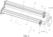
- the first rotation member 31 and the second rotation member 32 are arranged on the opposite sides of the first light transmitting member 431 and the second light transmitting member 432 from the first reading section 51 and the second reading section 52.
- the first rotation member 31 and the second rotation member 32 are rotation members that are arranged to face the first reading section 51 and the second reading section 52 and that are rotatable about the shaft 11.
- the airflow generation sections 54 are provided in the first rotation member 31 and the second rotation member 32.
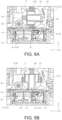
- the first rotation member 31 and the second rotation member 32 are configured so as to be rotatable and switchable between a first position P1 ( FIG. 6B ) at which airflow can be generated by directing the hole sections 53 toward the first light transmitting member 431 and the second light transmitting member 432, and at which airflow can be blown out, and a second position P2 ( FIG. 6A ) at which the hole sections 53 can stand by at a position farther from the first light transmitting member 431 and the second light transmitting member 432 than the first position P1.
- the second position P2 may be a position rotated 180 degrees from the position shown in FIG. 6A .
- the control section 71 determines whether the hole sections 53 are located at the first position P1 or the second position P2 based on information from a sensor (not shown) that detects the rotational positions in the rotational directions of the first rotation member 31 and the second rotation member 32, and the control section 71 stops the hole sections 53 at the first position P1 or the second position P2.
- the hole sections 53 of the first rotation member 31 located at the first position P1 is located at a position overlapping the first transport roller 4 when viewed from the transport direction F.
- the hole sections 53 of the second rotation member 32 located at the first position P1 may be located at a position overlapping the second transport roller 6 when viewed from the transport direction F.
- the hole sections 53 located at the first position P1 may be located at a position overlapping both the first transport roller 4 and the second transport roller 6 when viewed from the transport direction F.
- the hole sections 53 of the first rotation member 31 located at the first position P1 are located between the shaft 11 and the first light transmitting member 431 when viewed from an axial direction of the shaft 11.
- the hole sections 53 of the second rotation member 32 located at the first position P1 are located between the shaft 11 and the second light transmitting member 432 when viewed from an axial direction of the shaft 11.
- the axial direction of the shaft 11 may be referred to as a longitudinal direction of the shaft 11.
- the axial direction of the shaft 11 may be referred to as a direction orthogonal to the vertical direction and the transport direction F.
- the first rotation member 31 includes a first airflow generation section 531 as the airflow generation section 54
- the second rotation member 32 includes a second airflow generation section 532 as the airflow generation section 54.
- the first reading section 51, the first light transmitting member 431, and the second rotation member 32 are arranged above the transport path 2.
- the second reading section 52, the second light transmitting member 432, and the first rotation member 31 are arranged below the transport path 2.
- At least a part of the first reading section 51 overlaps the second rotation member 32 when viewed from the transport direction F, and at least a part of the second reading section 52 also overlaps the first rotation member 31 when viewed from the transport direction F.
- the first rotation member 31 and the second rotation member 32 are rotated about the shaft 11 by the power of the second drive source 27 which is a common drive source.
- reference numeral 75 denotes a power transmission mechanism.
- the second drive source 27 transmits power to the first rotation member 31 and the second rotation member 32 via the power transmission mechanism 75 to rotate them.
- the first rotation member 31 and the second rotation member 32 may be configured to rotate by the power of individual motors instead of the common second drive source 27.
- the first rotation member 31 and the second rotation member 32 are controlled by the control section 71 so as to rotate in the same rotational direction when the first rotation member 31 and the second rotation member 32 are rotated while airflow is blown out from the hole sections 53.
- the first rotation member 31 and the second rotation member 32 include a plurality of hole sections 53 in the longitudinal direction of the shaft 11.
- a plurality of hole sections 53 may be provided in the transport direction F.
- a plurality of the hole sections 53 may be provided in the direction of the shaft 11 and in the transport direction F.
- the hole sections 53 are configured to blow airflow from a direction orthogonal to the first light transmitting member 431 and the second light transmitting member 432.
- the airflow is not limited to be orthogonal to the target, and may be obliquely blown to the target.
- the first rotation member 31 and the second rotation member 32 may be rotated while blowing the airflow, or may be blown in a stopped state.
- the first airflow generation section 531 and the second airflow generation section 532 are arranged so as to overlap the first light transmitting member 431 and the second light transmitting member 432, respectively, when viewed from the vertical direction.
- the shafts 11 of the first rotation member 31 and the second rotation member 32 are arranged so as to overlap the first reading section 51 and the second reading section 52, respectively, when viewed from the vertical direction.
- the shafts 11 of the first rotation member 31 and the second rotation member 32 are arranged so as to overlap the first light transmitting member 431 and the second light transmitting member 432, respectively, when viewed in the vertical direction.
- the image reading device 1 includes a lower unit 55 and an upper unit 56.
- the upper unit 56 is configured to be capable of opening and closing by being rotated in the vertical direction with respect to the lower unit 55 by an opening and closing mechanism (not shown).
- the lower unit 55 includes the second reading section 52, the second light transmitting member 432, and the first airflow generation section 531.
- the upper unit 56 includes the first reading section 51, the first light transmitting member 431, and the second airflow generation section 532. In a state in which the upper unit 56 is closed with respect to the lower unit 55, as shown in FIG. 1 , the second light transmitting member 432 and the second airflow generation section 532 are arranged to face each other, and the first light transmitting member 431 and the first airflow generation section 531 are arranged to face each other.
- the second light transmitting member 432 and the second airflow generation section 532 do not face each other, and the first light transmitting member 431 and the first airflow generation section 531 do not face each other, although not shown. That is, facing surfaces of the lower unit 55 and the upper unit 56 become exposed, and a user can access the facing surfaces.
- a fan 45 for generating the airflow is provided.
- the fan 45 is connected to the first airflow generation section 531, the second airflow generation section 532, and a first duct 46A and a second duct 46B, which are the ducts 46 at respective longitudinal-direction end sections of the shafts 11.
- the first rotation member 31 and the second rotation member 32 basically have a cylindrical shape, and the airflow generated by the fan 45 passes through internal space sections 73 of the first rotation member 31 and the second rotation member 32, and is blown out to the outside from the hole sections 53 as shown in FIG. 4 .
- the fan 45 and the duct 46 are attached to the lower unit 55.
- a first connecting section 57 of the first duct 46A which is the duct 46, is connected to a first connected section 58 located at a longitudinal-direction end section of the shaft 11 of the first rotation member 31.
- a second connecting section 59 of the second duct 46B is connected to a second connected section 60 located at a longitudinal-direction end section of the shaft 11 of the second rotation member 32.
- the first rotation member 31 and the second rotation member 32 are provided with respective first brushes 63.
- the first brushes 63 clean the first light transmitting member 431 and the second light transmitting member 432.
- the first brushes 63 are configured so as to be in contact with corresponding ones of the first light transmitting member 431 and the second light transmitting member 432, when the first rotation member 31 and the second rotation member 32 are at the first position P1 ( FIG. 6B ), and so as not to be in contact with the first light transmitting member 431 and the second light transmitting member 432 when the first rotation member 31 and the second rotation member 32 are at the second position ( FIG. 6A ).
- the first rotation member 31 and the second rotation member 32 move from the second position P2 ( FIG. 6A ) to the first position P1 ( FIG. 6B ), the first brushes 63 come into contact with the first light transmitting member 431 and the second light transmitting member 432, and then the hole sections 53 of the airflow generation sections 54 pass through a position facing the first light transmitting member 431 and the second light transmitting member 432, so that cleaning by the airflow is performed after cleaning by the first brushes 63.
- the light transmitting member 43 may be cleaned by the airflow and then cleaned by the first brush 63.
- the first brush 63 is not limited to the position shown in FIG. 6B , that is, a position on an upstream side of the hole sections 53, but may be arranged on a downstream side which is a symmetrical position opposite to the hole sections 53.
- the contact angle of the first brush 63 with respect to the light transmitting member 43 is not necessarily a right angle as shown in FIG. 6B , but may be inclined.
- each of the first rotation member 31 and the second rotation member 32 is provided with a white background section 91 and a black background section 92 as a background section 9 on a peripheral surface 13 ( FIG. 1 ) at positions different from the hole sections 53.
- the white background section 91 or the black background section 92 is positioned so as to face the first light transmitting member 431 and the second light transmitting member 432, respectively.
- each of the hole sections 53 of each of the airflow generation sections 54 is arranged between the white background section 91 and the black background section 92 in the transport direction F.
- a first transport assistance section 61 and a second transport assistance section 62 are provided as transport assistance sections that face the first light transmitting member 431 and the second light transmitting member 432, are arranged upstream of the first rotation member 31 and the second rotation member 32, and assist transport of the medium 3.
- the first transport assistance section 61 and the second transport assistance section 62 are constituted by drive rollers 26, which are referred to as platen rollers 26, to which the power of the first drive source 15 is transmitted to rotate.
- the first brush 63 is configured such that the first rotation member 31 and the second rotation member 32 come into contact with the first transport assistance section 61 and the second transport assistance section 62 at a position different from the first position P1 ( FIG. 6B ) and the second position P2 ( FIG. 6A ), and the first brushes 63 can clean the first transport assistance section 61 and the second transport assistance section 62.
- a position different from the first position P1 and the second position P2 is a position in a state in which the first rotation member 31 and the second rotation member 32 further rotate clockwise from the second position P2 ( FIG. 6A ), pass through the first position P1, and the first brushes 63 come into contact with the first transport assistance section 61 and the second transport assistance section 62.
- the cleaning operation is performed in a state in which the platen roller 26 is driven by the first drive source 15 and the first rotation member 31 and the second rotation member 32 are stopped for cleaning.
- the platen rollers 26 may be rotated at higher speeds than the rotated first rotation member 31 and rotated the second rotation member 32, in other words, the first rotation member 31 and the second rotation member 32 may clean in a state of being rotated slowly. By rotating both of them for cleaning, it is possible to prevent dust from remaining on the first brush 63, and the first brush 63 is less likely to be worn.
- the image reading device 1 according to a second embodiment will be described with reference to FIG. 8 .
- the same sections as those in the first embodiment are denoted by the same reference numerals, and the description of the configuration and the corresponding effects is omitted.
- the color reference members 64 provided on the first rotation member 31 and the second rotation member 32 and having a uniform reflectivity, and the second brushes 65 which clean the color reference members 64 are provided.
- the color reference member 64 is arranged on the opposite side of the shaft 11 from the hole sections 53.
- the first rotation member 31, the second rotation member 32, the first transport assistance section 61, and the second transport assistance section 62 are integrally connected to each other by a pair of coupling members 17 (refer to FIGS. 6A and 6B ) located on one end side and the other end side in the width direction of the medium 3, which is the longitudinal direction (X-axis direction) of the first rotation member 31, the second rotation member 32, the first transport assistance section 61, and the second transport assistance section 62.
- the first rotation member 31, the second rotation member 32, the first transport assistance section 61, and the second transport assistance section 62 are configured to integrally move in an upward direction (+Z direction) via the coupling member 17.
- the second brush 65 is fixed to the coupling member 17.
- the second brush 65 is configured to be able to clean the color reference member 64 when the first rotation member 31 and the second rotation member 32 are rotated and come into contact with the color reference member 64.
- the second brush 65 cleans the color reference member 64 when the rotation members 31 and 32 rotate and come into contact with the color reference member 64.
- dust such as paper dust clinging to the color reference member 64 can be cleaned by the second brush 65.
- the color reference member 64 is arranged on the opposite side of the shaft 11 from the hole section 53, dirt such as dust blown by the airflow is less likely to contaminate as compared with a case where the color reference member 64 is arranged on another section.
- the image reading device 1 according to a third embodiment will be described with reference to FIG. 9 .
- the same sections as those in the first embodiment and the second embodiment are denoted by the same reference numerals, and the description of the configuration and the corresponding effects is omitted.
- the first transport assistance section 61 and the second transport assistance section 62 are provided that face the first light transmitting member 431 and the second light transmitting member 432, that are arranged upstream of the first rotation member 31 and the second rotation member 32, and that assist transport of the medium 3.
- the hole section 53 of the airflow generation section 54 is configured such that when the first rotation member 31 and the second rotation member 32 are at a third position P3 (the position in FIG. 9 ) different from the first position P1 and the second position P2, the hole section 53 faces the first transport assistance section 61 and the second transport assistance section 62 so that the first transport assistance section 61 and second transport assistance section 62 can be cleaned by airflow generated from the hole section 53.
- both the cleaning by the first brush 63 and the cleaning by the airflow can be received.
- the airflow generation section 54 when the rotation members 31 and 32 are at the third position P3, which is different from the first position P1 and the second position P2, the airflow generation section 54 is configured such that the hole section 53 faces the transport assistance sections 61 and 62 so that the transport assistance sections 61 and 62 can be cleaned by airflow generated from the hole section 53.
- the airflow generation section 54 can clean the transport assistance sections 61 and 62.
- the image reading device 1 according to a fourth embodiment will be described with reference to FIG. 7 .
- the same sections as those in the first to third embodiments are denoted by the same reference numerals, and the description of the configuration and the corresponding effects are omitted.
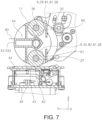
- the first rotation member 31 and the second rotation member 32 includes a rotation white background section 81 configured to rotate about a first rotation shaft 36 different from the shaft 11 and the rotation black background section 82 configured to rotate about a second rotation shaft 37 different from the shaft 11 and the first rotation shaft 36 at positions different from the hole section 53.
- the rotation white background section 81 and the rotation black background section 82 are constituted by a drive roller 26 having a cylindrical outer shape, include a white peripheral surface 29 and a black peripheral surface 30, and rotate by power transmitted from the first drive source 15 by a power transmission mechanism (not shown).
- the first rotation member 31 and the second rotation member 32 are configured to rotate to a position where the rotation white background section 81 or the rotation black background section 82 faces the light transmitting member 43 when an image of the medium 3 is read.
- the rotation white background section 81 and the rotation black background section 82 which are the drive rollers 26, are configured such that when the first rotation member 31 and the second rotation member 32 are rotated about the shaft 11, the power transmission state with the first drive source 15 by the power transmission mechanism is switched to a power non-transmission state.
- the airflow generation section 54 includes other hole sections 66 and 67 other than the hole section 53. Further, cleaning is performed by blowing airflow from the other hole sections 66 and 67 toward the rotation white background section 81 and the rotation black background section 82 when the first rotation member 31 and the second rotation member 32 are at the second position P2, that is, in a state in which the hole sections 53 do not face the first light transmitting member 431 and the second light transmitting member 432 ( FIG. 7 ).
- the rotation members 31 and 32 are rotated to position the rotation white background section 81 or the rotation black background section 82 so as to face the light transmitting member 43.
- the rotation white background section 81 and the rotation black background section 82 come into contact with the transported medium 3 while rotating, it is possible to stabilize the transportation of the medium 3 at the time of reading by the reading sections 51 and 52, and thus, reading quality is stabilized.
- the image reading device 1 basically includes the configuration of the above-described embodiment, it is of course possible to change or omit the partial configuration without departing from the scope of the present disclosure.
- an image reading device that includes the first reading section 51 and the second reading section 52 as reading sections and can read both sides of the first side and the second side of the medium 3 has been described, but the present disclosure can also be applied to an image reading device including a single-sided reading structure.
- the airflow generation section 54 is described as a structure for blowing out airflow from the hole sections 53, but the present disclosure is not limited to this.
- the airflow generation section 54 may be configured to suck airflow from the hole sections 53 to generate airflow in the light transmitting member 43. By adopting this suction structure, it is possible to obtain an effect of not dispersing the cleaned dust to the surroundings in addition to the effect of the blowing structure.
- the present disclosure is also applicable to a device including no curved inversion path 18.
Landscapes
- Engineering & Computer Science (AREA)
- Multimedia (AREA)
- Signal Processing (AREA)
- Environmental & Geological Engineering (AREA)
- Facsimile Scanning Arrangements (AREA)
- Facsimiles In General (AREA)
Abstract
A image reading device includes a reading section configured to read an image of a medium transported in a transport direction;a light transmitting member arranged between a transport path on which the medium is transported and the reading section; and an airflow generation section which is arranged on an opposite side of the light transmitting member from the reading section, which includes a hole section positioned facing the light transmitting member, and which is configured to generate airflow from the hole section toward the light transmitting member.
Description
- The present application is based on, and claims priority from
JP Application Serial Number 2023-045099, filed March 22, 2023 - The present disclosure relates to an image reading device.
- An example of this type of device is described in
JP-A-2008-297023 JP-A-2008-297023 - The device described in
JP-A-2008-297023 - In order to solve the above-described problem, an image reading device according to the present disclosure includes a reading section configured to read an image of a medium transported in a transport direction; a light transmitting member arranged between a transport path on which the medium is transported and the reading section; and an airflow generation section that is arranged on an opposite side of the light transmitting member from the reading section, that includes a hole section positioned facing the light transmitting member, and that is configured to generate airflow from the hole section toward the light transmitting member.
-
-
FIG. 1 is a schematic configuration view of main parts of the inside of an image reading device according to a first embodiment, as viewed from the side. -
FIG. 2 is a perspective view of a main part of the first embodiment. -
FIGS. 3A and 3B are a perspective view of a main part and a partially enlarged view of the first embodiment. -
FIG. 4 is a front view of a main part of the first embodiment, with a part thereof in cross section. -
FIG. 5 is a perspective view of a main part of the first embodiment. -
FIGS. 6A and 6B are side cross-sectional views of a main part of the first embodiment. -
FIG. 7 is a side cross-sectional view of a main part of a fourth embodiment. -
FIG. 8 is a side cross-sectional view of a main part of a second embodiment. -
FIG. 9 is a side cross-sectional view of a main part of a third embodiment. - Hereinafter, the present disclosure will be briefly described.
- In order to solve the above-described problem, an image reading device according to a first aspect of the present disclosure includes a reading section configured to read an image of a medium transported in a transport direction; a light transmitting member arranged between a transport path on which the medium is transported and the reading section; and an airflow generation section that is arranged on an opposite side of the light transmitting member from the reading section, that includes a hole section positioned facing the light transmitting member, and that is configured to generate airflow from the hole section toward the light transmitting member.
- According to the present aspect, since the image reading device includes the airflow generation section which includes a hole section positioned facing the light transmitting member, and which is configured to generate airflow from the hole section toward the light transmitting member, the light transmitting member serving as a reading surface of the reading section can be effectively cleaned.
- A second aspect of the image reading device according to the present disclosure is an aspect dependent on the first aspect, and the image reading device further includes a rotation member that is arranged to face the reading section on an opposite side of the light transmitting member from the reading section and that is configured to rotate about a shaft, wherein the airflow generation section is provided to the rotation member and the rotation member is configured to rotate and switch between a first position at which the hole section faces the light transmitting member and a second position at which the hole section stands by at a position farther from the light transmitting member than the first position.
- According to the present aspect, the airflow generation section is provided on the rotation member. The rotation member is configured to rotate and switch between a first position at which the hole section is configured to blow out airflow toward the light transmitting member and a second position at which the hole section stands by at a position farther from the light transmitting member than the first position. Thus, by rotating the rotation member, the light transmitting member serving as a reading surface of the reading section can be cleaned when necessary.
- A third aspect of the image reading device according to the present disclosure is an aspect dependent on the second aspect, and the rotation member includes a plurality of the hole sections in a longitudinal direction of the shaft.
- According to the present aspect, since the rotation member includes a plurality of the hole sections in a longitudinal direction of the shaft, substantially uniform cleaning can be performed over the entire reading surface of the reading section in a width direction.
- A fourth aspect of the image reading device according to the present disclosure is an aspect dependent on the second aspect, and at the first position, the hole section generates the airflow from a direction orthogonal to the light transmitting member.
- The present aspect can also be dependent on the third aspect.
- According to this aspect, the hole section blows airflow from a direction orthogonal to the light transmitting member at the first position. As a result, stronger airflow can be blown to the light transmitting member so that more effective cleaning can be performed.
- A fifth aspect of the image reading device according to the present disclosure is an aspect dependent on the second aspect, and the airflow generation section overlaps the light transmitting member when viewed from a vertical direction.
- The present aspect can also be dependent on the third aspect or the fourth aspect.
- According to the present aspect, the airflow generation section is arranged so as to overlap the light transmitting member when viewed from the vertical direction. As a result, stronger airflow can be blown to the light transmitting member so that more effective cleaning can be performed.
- A sixth aspect of the image reading device according to the present disclosure is an aspect dependent on the second aspect, and the image reading device further includes a fan configured to cause the airflow, wherein the fan is connected to the airflow generation section via a duct at a longitudinal-direction end section of the shaft.
- The present aspect can also be dependent on any one of the third to fifth aspects.
- According to the present aspect, the image reading device includes a fan configured to cause airflow, and the fan is connected to the airflow generation section via a duct at a longitudinal-direction end section of the shaft. As a result, the duct is connected to an end section of the rotation member in an axial direction, so that an increase in size in a height direction can be suppressed.
- A seventh aspect of the image reading device according to the present disclosure is an aspect dependent on the second aspect, and the reading section includes a first reading section and a second reading section, the light transmitting member includes a first light transmitting member and a second light transmitting member, the rotation member includes a first rotation member including a first airflow generation section and a second rotation member including a second airflow generation section, the first reading section, the first light transmitting member, and the second rotation member are provided above the transport path, and the second reading section, the second light transmitting member, and the first rotation member are provided below the transport path.
- The present aspect can also be dependent on any one of the third to sixth aspects.
- According to the present aspect, the first reading section, the first light transmitting member, and the second rotation member are provided above the transport path, and the second reading section, the second light transmitting member, and the first rotation member are provided below the transport path. As a result, in the image reading device capable of reading both sides of the medium, the first light transmitting member and the second light transmitting member serving as the reading surface can be effectively cleaned.
- An eighth aspect of the image reading device according to the present disclosure is an aspect dependent on the seventh aspect, and the image reading device further includes a lower unit and an upper unit configured to open and close relative to the lower unit, wherein the lower unit includes the second reading section, the second light transmitting member, and the first airflow generation section, the upper unit includes the first reading section, the first light transmitting member, and the second airflow generation section, in a state where the upper unit is closed, the second light transmitting member and the second airflow generation section face each other, and the first light transmitting member and the first airflow generation section face each other, and in a state where the upper unit is open, the second light transmitting member and the second airflow generation section do not face each other, and the first light transmitting member and the first airflow generation section do not face each other.
- According to the present aspect, in a state where the upper unit is open, the second light transmitting member and the second airflow generation section do not face each other, and the first light transmitting member and the first airflow generation section do not face each other. As a result, the upper unit can be kept in an open state to clean the inside, thereby increasing convenience for a user.
- A ninth aspect of the image reading device according to the present disclosure is an aspect dependent on the eighth aspect, and the image reading device further includes a fan as a generation source of the airflow, wherein the fan is connected to the airflow generation section via a duct at a longitudinal-direction end section of the shaft, the fan and the duct are attached to the lower unit, a first connecting section of the duct is connected to a first connected section located at a longitudinal-direction end section of the shaft of the first rotation member, a second connecting section of the duct is configured to detach and attach to be connected to a second connected section located at a longitudinal-direction end section of the shaft the second rotation member, and when the upper unit is opened with respect to the lower unit, the second connecting section separates from the second connected section while the first connecting section remains connected to the first connected section.
- According to the present aspect, when the upper unit is opened with respect to the lower unit, the second connecting section separates from the second connected section while the first connecting section remains connected to the first connected section. In this configuration, the duct is connected to the upper unit and the lower unit, but the second connecting section can be separated from the second connected section, so that the upper unit can be opened, thereby facilitating maintenance.
- A tenth aspect of the image reading device according to the present disclosure is an aspect dependent on the second aspect, and the image reading device further includes a first brush provided on the rotation member and configured to clean the light transmitting member, wherein when the rotating member is at the first position, the first brush is in contact with the light transmitting member, and when the rotation member is at the second position, the first brush is not in contact with the light transmitting member.
- The present aspect can also be dependent on any one of the third to ninth aspects.
- According to the present aspect, when the rotating member is at the first position, the first brush is in contact with the light transmitting member, and when the rotation member is at the second position, the first brush is not in contact with the light transmitting member. As a result, dust such as paper dust clinging to the light transmitting member can be cleaned by the first brush.
- An eleventh aspect of the image reading device according to the present disclosure is an aspect dependent on the tenth aspect, and when the rotation member moves from the second position to the first position, the first brush comes into contact with the light transmitting member, and then the hole section passes through a position facing the light transmitting member.
- According to the present aspect, when the rotation member moves from the second position to the first position, the first brush comes into contact with the light transmitting member, and then the hole section passes through a position facing the light transmitting member. As a result, after the light transmitting member is cleaned by the first brush, the airflow blown out from the hole section allows more effective cleaning.
- A twelfth aspect of the image reading device according to the present disclosure is an aspect dependent on the second aspect, and the rotation member includes a white background section and a black background section at positions different from the hole section, and when the medium is to be read, the rotation member rotates to position the white background section or the black background section to face the light transmitting member.
- The present aspect can also be dependent on any one of the third to eleventh aspects.
- According to the present aspect, when the medium is read, the rotation member rotates to position so that the white background section or the black background section faces the light transmitting member. As a result, it is possible to switch between the white background section and the black background section in accordance with the type of the medium.
- A thirteenth aspect of the image reading device according to the present disclosure is an aspect dependent on the twelfth aspect, and the hole section is arranged between the white background section and the black background section in the transport direction when the rotation member is at the first position.
- According to the present aspect, the hole section is arranged between the white background section and the black background section in the transport direction when the rotation member is at the first position. As a result, after the light transmitting member is cleaned by the airflow, whichever of the white background section and the black background section is made to face the light transmitting member by rotating the rotation member, the white background section and the black background section can be positioned by substantially the same rotation amount.
- A fourteenth aspect of the image reading device according to the present disclosure is an aspect dependent on the second aspect, and the rotation member includes a rotation white background section configured to rotate about a first rotation shaft different from the shaft and a rotation black background section configured to rotate about a second rotation shaft different from the shaft and the first rotation shaft at a position different from the hole section, and when the medium is read, the rotation member rotates to position so that the rotation white background section or the rotation black background section faces the light transmitting member.
- The present aspect can also be dependent on any one of the third to thirteenth aspects.
- According to the present aspect, when an image of the medium is read, the rotation member rotates to position so that the rotation white background section or the rotation black background section faces the light transmitting member. As a result, since the rotation white background section and the rotation black background section come into contact with a transported medium while rotating, it is possible to stabilize a transportation of the medium at the time of reading by the reading section, and thus, reading quality is stabilized.
- A fifteenth aspect of the image reading device according to the present disclosure is an aspect dependent on the second aspect, and the image reading device further includes a color reference member provided on the rotation member and configured to have a uniform reflectance and a second brush configured to clean the color reference member, wherein the second brush cleans the color reference member when the rotation member rotates and comes into contact with the color reference member.
- The present aspect can also be dependent on any one of the third to fourteenth aspects.
- According to the present aspect, the second brush cleans the color reference member when the rotation member rotates and comes into contact with the color reference member. As a result, dust such as paper dust clinging to the color reference member can be cleaned by the second brush.
- A sixteenth aspect of the image reading device according to the present disclosure is an aspect dependent on the fifteenth aspect, and the color reference member is arranged on an opposite side of the shaft from the hole section.
- According to the present aspect, since the color reference member is arranged on an opposite side of shaft from the hole section, dirt such as dust blown by the airflow is less likely to be contaminated as compared with a case where the color reference member is arranged on another section.
- A seventeenth aspect of the image reading device according to the present disclosure is an aspect dependent on the seventh aspect, and at least a part of the first reading section overlaps the second rotation member when viewed from the transport direction and at least a part of the second reading section overlaps the first rotation member when viewed from the transport direction.
- The present aspect can also be dependent on the eighth aspect or the ninth aspect.
- According to the present aspect, at least a part of the first reading section overlaps the second rotation member when viewed from the transport direction, and at least a part of the second reading section overlaps the first rotation member when viewed from the transport direction. That is, since the first reading section and the second reading section are not arranged so as to face each other in the vertical direction, but are arranged so as to be offset from each other, it is possible to arrange the first rotation member and the second rotation member on the facing sides of the first reading section and the second reading section, thereby suppressing an increase in the size in a height direction.
- An eighteenth aspect of the image reading device according to the present disclosure is an aspect dependent on the seventh aspect, and the first rotation member and the second rotation member are rotated by a common drive source.
- The present aspect can also be dependent on the eighth aspect or the ninth aspect.
- According to the present aspect, since the first rotation member and the second rotation member use a common motor as a drive source for rotation, it is possible to suppress increase in size compared to a case where separate motors are used.
- A nineteenth aspect of the image reading device according to the present disclosure is an aspect dependent on the fourteenth aspect, and the airflow generation section includes another hole section, and generates airflow from the other hole section toward the rotation white background section and the rotation black background section when the rotation member is at the second position.
- The present aspect can also be dependent on any one of the third to thirteenth aspects.
- According to this aspect, the airflow generation section generates airflow from the other hole section toward the rotation white background section and the rotation black background section when the rotation member is at the second position. As a result, paper dust clinging to the rotation white background section and the rotation black background section can be removed.
- A twentieth aspect of the image reading device according to the present disclosure is an aspect dependent on the tenth aspect, and the image reading device further includes a transport assistance section that faces the light transmitting member, that is arranged upstream of the rotation member, and that assists transport of the medium, wherein the first brush is configured to come into contact with the transport assistance section at a position different from the first position and the second position of the rotation member and to clean the transport assistance section.
- According to the present aspect, the first brush is configured to come into contact with the transport assistance section at a position different from the first position and the second position of the rotation member and clean the transport assistance section. As a result, the transport assistance section can be cleaned by using the first brush provided on the rotation member.
- A twenty first aspect of the image reading device according to the present disclosure is an aspect dependent on the second aspect, and the image reading device further includes a transport assistance section that faces the light transmitting member, that is arranged upstream of the rotation member, and that assists transport of the medium, wherein when the rotation member is at a third position different from the first position and the second position, the airflow generation section is configured such that the hole section faces the transport assistance section and the transport assistance section is configured be cleaned by airflow blown out from the hole section.
- The present aspect can also be dependent on any one of the third to twentieth aspects.
- According to the present aspect, when the rotation member is at a third position different from the first position and the second position, the airflow generation section is configured such that the hole section faces the transport assistance section and the transport assistance section is configured be cleaned by airflow generated from the hole section. As a result, the airflow generation section can clean the transport assistance section.
- A twenty second aspect of the image reading device according to the present disclosure is an aspect dependent on the second aspect, and the transport path includes a straight path in which the reading section is arranged, and a curved inversion path located downstream of the straight path and a discharge receiving section that receives the medium discharged from the curved inversion path is arranged above the straight path.
- The present aspect can also be dependent on any one of the third to twenty first aspects.
- According to the present aspect, the transport path includes a straight path, and a curved inversion path and a discharge receiving section that receives the medium discharged from the curved inversion path is arranged above the straight path. As a result, it is possible to suppress an increase in the size of the device in a height direction.
- A twenty third aspect of the image reading device according to the present disclosure is an aspect dependent on the seventh aspect, and the first rotation member and the second rotation member rotate in a same rotational direction when they rotate in a state where the airflow is generated from the hole section.
- The present aspect can also be dependent on the eighth aspect or the ninth aspect.
- According to the present aspect, the first rotation member and the second rotation member rotate in a same rotational direction when they rotate in a state where the airflow is generated from the hole section. As a result, it is possible to suppress dust blown by the airflow from clinging to the reading section on one side.
- Hereinafter, an embodiment of an image reading device according to the present disclosure will be described in detail with reference to
FIG. 1 to FIGS. 6A and6B . - In the following description, three axes orthogonal to each other are referred to as an X-axis, a Y-axis, and a Z-axis, as shown in the drawings. A direction indicated by arrows of three axes (X, Y, Z) is a + direction of each direction, and the reverse is a - direction. A Z-axis direction corresponds to the vertical direction, that is, a direction in which gravity acts, and a +Z direction indicates the vertically upward direction and a -Z direction indicates the vertically downward direction. A X-axis direction and a Y-axis direction correspond to the horizontal direction. A +Y direction indicates a forward direction of a device and a -Y direction indicates a backward direction of the device. A +X direction indicates a right direction of the device, and the -X direction indicates a left direction of the device.
- An image reading device 1 of the present embodiment is a scanner capable of reading an image of a medium serving as a document. Here, the image is visually recorded on the medium, for example, a character, a figure, a table, a picture, a photograph, or the like. The medium is not limited to a sheet, but includes a card, a booklet, and the like.
- As shown in
FIG. 1 , the image reading device 1 includes afirst reading section 51 and asecond reading section 52 that read an image of a medium 3, a first transport roller 4 that transports the medium 3 along atransport path 2 in a transport direction F and provided upstream of thefirst reading section 51 in the transport direction F, a second transport roller 6 provided upstream of thesecond reading section 52 located downstream of thefirst reading section 51, and a third transport roller 8 provided downstream of thesecond reading section 52. - A roller pair of a
feed roller 10 and a separation roller 7 is arranged upstream of the first transport roller 4 in the transport direction F. Thefeed roller 10 is a drive roller rotated by the power of afirst drive source 15, and transports the medium 3 in the transport direction F. The separation roller 7 is a drive roller that is rotated by the power of a drive source (not shown), and separates a plurality of sheets of the medium 3 into one sheet. - Here, the separation roller 7 rotates in a rotational direction for feeding the medium 3 to an upstream side (+Y direction) of the transport direction F by the power of the drive source. The separation roller 7 includes a torque limiter (not shown), and when a torque exceeding a set value is applied to the torque limiter, the separation roller 7 is driven to rotate in a rotational direction for feeding the medium 3 to a downstream side (-Y direction) in the transport direction F.
- A
pickup roller 12 is arranged upstream of the separation roller 7. Thepickup roller 12 is a drive roller that is rotated by the power of thefirst drive source 15 which is the same as that of thefeed roller 10, and transports the medium 3 in the transport direction F. The first transport roller 4, the second transport roller 6, and the third transport roller 8 constituting the transport section 5 that transports the medium 3 in the transport direction F are also provided with drive rollers rotated by the power of thefirst drive source 15. - As shown in
FIG. 1 , in the present embodiment, acurved inversion path 18 is provided downstream of astraight path 68 from thefeed roller 10 to the third transport roller 8, that is, downstream of the third transport roller 8. In thecurved inversion path 18, the fourth transport roller 20, the fifth transport roller 22, and the discharge roller 24 are arranged in this order along the transport direction F. - The
discharge receiving section 16 that receives the medium 3 discharged from thecurved inversion path 18 is arranged above thestraight path 68 to achieve a compact configuration. - In
FIG. 1 ,reference numeral 71 denotes a control section. Thecontrol section 71 controls the drive of thefirst drive source 15 and the drive of thesecond drive source 27 described later in correspondence with the transport of the medium 3. Thefirst drive source 15 and thesecond drive source 27 are constituted by motors. Thecontrol section 71 includes a CPU, a flash ROM, and a RAM. The CPU performs various kinds of arithmetic processing in accordance with a program stored in the flash ROM and controls operation of the entire image reading device 1. A flash ROM, which is an example of storage unit, is a nonvolatile memory capable of reading and writing. Various kinds of information are temporarily stored in the RAM, which is an example of the storage unit. - In
FIG. 1 ,reference numeral 14 denotes a medium placement section for setting the medium 3 to be read, andreference numeral 16 denotes a discharge receiving section for discharging the medium 3 that has been read. - The
medium placement section 14 is configured to move vertically. In a case where the medium 3 that is set on themedium placement section 14 is fed in the transport direction F, first, themedium placement section 14 moves upward (+Z direction), and stops in a state where the uppermost sheet of the set medium 3 is in contact with thepickup roller 12. In this state, thepickup roller 12 rotates to feed the medium 3 in the transport direction F, and a leading edge of the medium 3 reaches a nip position of a roller pair of thefeed roller 10 and the separation roller 7. - In a case of a multi-feed state in which the medium 3 is fed in a plurality of sheets, the medium 3 is separated into one sheet by the separation roller 7, the one sheet is transported in the transport direction F by the first transport roller 4, and the image on a first surface of the medium 3 is read by the
first reading section 51. Further, the medium 3 read by thefirst reading section 51 is transported by the second transport roller 6, and an image of a second surface opposite to the first surface of the medium 3 is read by thesecond reading section 52. - The medium 3 read by the
second reading section 52 is fed to thecurved inversion path 18 by the third transport roller 8, transported by the fourth transport roller 20 and the fifth transport roller 22, and discharged to thedischarge receiving section 16 by the discharge roller 24. - As shown in
FIG. 1 ,FIGS. 3A and 3B ,FIG. 4 , andFIGS. 6A and 6B , in the present embodiment, the image reading device includes thefirst reading section 51 and asecond reading section 52 as reading sections for reading an image of the medium 3 transported in the transport direction F, and a first light transmitting member 431 and a second light transmitting member 432 as light transmittingmembers 43 arranged between thetransport path 2 on which the medium 3 is transported and thefirst reading section 51 and thesecond reading section 52. - In
FIGS. 6A and 6B ,reference numeral 42 denotes a reading position of thesecond reading section 52, andreference numeral 44 denotes an inclined surface. Theinclined surface 44 is provided at an upstream end section of thelight transmitting member 43 on the reading surface side, and guides a leading edge of the medium 3 along thetransport path 2. - Further, on the opposite side of the first light transmitting member 431 and the second light transmitting member 432 from the
first reading section 51 and thesecond reading section 52, theairflow generation sections first reading section 51 and thesecond reading section 52. Theairflow generation sections hole sections hole sections - In the present embodiment, the
airflow generation section 54 is configured to blow out airflow from thehole sections 53 to the outside and apply the airflow to thelight transmitting member 43. - Here, the
airflow generation section 54 is configured such that when a power supply of the image reading device 1 is turned on, a fan 45 (to be described later) is driven to blow out airflow from thehole sections 53. The timing at which airflow is blown out from thehole sections 53 is not limited to the time when the power supply is turned on, and may be performed at an appropriate timing such as after the image of the medium 3 is read by the readingsections transport path 2 is processed. Alternatively, a sensor such as an encoder that detects contamination of the first light transmitting member 431 and the second light transmitting member 432 may be provided, and airflow may be blown out based on sensing information of the sensor. Alternatively, a switch for generating airflow may be provided, and the switch may be turned on by a user's judgment to blow out the airflow. - The
first rotation member 31 and thesecond rotation member 32 are arranged on the opposite sides of the first light transmitting member 431 and the second light transmitting member 432 from thefirst reading section 51 and thesecond reading section 52. Thefirst rotation member 31 and thesecond rotation member 32 are rotation members that are arranged to face thefirst reading section 51 and thesecond reading section 52 and that are rotatable about theshaft 11. - The
airflow generation sections 54 are provided in thefirst rotation member 31 and thesecond rotation member 32. Thefirst rotation member 31 and thesecond rotation member 32 are configured so as to be rotatable and switchable between a first position P1 (FIG. 6B ) at which airflow can be generated by directing thehole sections 53 toward the first light transmitting member 431 and the second light transmitting member 432, and at which airflow can be blown out, and a second position P2 (FIG. 6A ) at which thehole sections 53 can stand by at a position farther from the first light transmitting member 431 and the second light transmitting member 432 than the first position P1. The second position P2 may be a position rotated 180 degrees from the position shown inFIG. 6A . - The
control section 71 determines whether thehole sections 53 are located at the first position P1 or the second position P2 based on information from a sensor (not shown) that detects the rotational positions in the rotational directions of thefirst rotation member 31 and thesecond rotation member 32, and thecontrol section 71 stops thehole sections 53 at the first position P1 or the second position P2. - As shown in
FIG. 1 , thehole sections 53 of thefirst rotation member 31 located at the first position P1 is located at a position overlapping the first transport roller 4 when viewed from the transport direction F. Thehole sections 53 of thesecond rotation member 32 located at the first position P1 may be located at a position overlapping the second transport roller 6 when viewed from the transport direction F. Thehole sections 53 located at the first position P1 may be located at a position overlapping both the first transport roller 4 and the second transport roller 6 when viewed from the transport direction F. - The
hole sections 53 of thefirst rotation member 31 located at the first position P1 are located between theshaft 11 and the first light transmitting member 431 when viewed from an axial direction of theshaft 11. Thehole sections 53 of thesecond rotation member 32 located at the first position P1 are located between theshaft 11 and the second light transmitting member 432 when viewed from an axial direction of theshaft 11. The axial direction of theshaft 11 may be referred to as a longitudinal direction of theshaft 11. The axial direction of theshaft 11 may be referred to as a direction orthogonal to the vertical direction and the transport direction F. - As shown in
FIG. 1 , thefirst rotation member 31 includes a first airflow generation section 531 as theairflow generation section 54, and thesecond rotation member 32 includes a second airflow generation section 532 as theairflow generation section 54. - The
first reading section 51, the first light transmitting member 431, and thesecond rotation member 32 are arranged above thetransport path 2. Thesecond reading section 52, the second light transmitting member 432, and thefirst rotation member 31 are arranged below thetransport path 2. - At least a part of the
first reading section 51 overlaps thesecond rotation member 32 when viewed from the transport direction F, and at least a part of thesecond reading section 52 also overlaps thefirst rotation member 31 when viewed from the transport direction F. - As shown in
FIG. 5 , thefirst rotation member 31 and thesecond rotation member 32 are rotated about theshaft 11 by the power of thesecond drive source 27 which is a common drive source. InFIG. 5 ,reference numeral 75 denotes a power transmission mechanism. Thesecond drive source 27 transmits power to thefirst rotation member 31 and thesecond rotation member 32 via thepower transmission mechanism 75 to rotate them. Thefirst rotation member 31 and thesecond rotation member 32 may be configured to rotate by the power of individual motors instead of the commonsecond drive source 27. - The
first rotation member 31 and thesecond rotation member 32 are controlled by thecontrol section 71 so as to rotate in the same rotational direction when thefirst rotation member 31 and thesecond rotation member 32 are rotated while airflow is blown out from thehole sections 53. - In the present embodiment, as shown in
FIGS. 3A, 3B and4 , thefirst rotation member 31 and thesecond rotation member 32 include a plurality ofhole sections 53 in the longitudinal direction of theshaft 11. A plurality ofhole sections 53 may be provided in the transport direction F. Alternatively, a plurality of thehole sections 53 may be provided in the direction of theshaft 11 and in the transport direction F. - At the first position P1, the
hole sections 53 are configured to blow airflow from a direction orthogonal to the first light transmitting member 431 and the second light transmitting member 432. The airflow is not limited to be orthogonal to the target, and may be obliquely blown to the target. Thefirst rotation member 31 and thesecond rotation member 32 may be rotated while blowing the airflow, or may be blown in a stopped state. - The first airflow generation section 531 and the second airflow generation section 532 are arranged so as to overlap the first light transmitting member 431 and the second light transmitting member 432, respectively, when viewed from the vertical direction. As shown in
FIG. 1 , theshafts 11 of thefirst rotation member 31 and thesecond rotation member 32 are arranged so as to overlap thefirst reading section 51 and thesecond reading section 52, respectively, when viewed from the vertical direction. Theshafts 11 of thefirst rotation member 31 and thesecond rotation member 32 are arranged so as to overlap the first light transmitting member 431 and the second light transmitting member 432, respectively, when viewed in the vertical direction. - As shown in
FIG. 1 , in the present embodiment, the image reading device 1 includes alower unit 55 and anupper unit 56. Theupper unit 56 is configured to be capable of opening and closing by being rotated in the vertical direction with respect to thelower unit 55 by an opening and closing mechanism (not shown). - The
lower unit 55 includes thesecond reading section 52, the second light transmitting member 432, and the first airflow generation section 531. Theupper unit 56 includes thefirst reading section 51, the first light transmitting member 431, and the second airflow generation section 532. In a state in which theupper unit 56 is closed with respect to thelower unit 55, as shown inFIG. 1 , the second light transmitting member 432 and the second airflow generation section 532 are arranged to face each other, and the first light transmitting member 431 and the first airflow generation section 531 are arranged to face each other. In a state where theupper unit 56 is open with respect to thelower unit 55, the second light transmitting member 432 and the second airflow generation section 532 do not face each other, and the first light transmitting member 431 and the first airflow generation section 531 do not face each other, although not shown. That is, facing surfaces of thelower unit 55 and theupper unit 56 become exposed, and a user can access the facing surfaces. - As shown in
FIGS. 2 to 4 , in the present embodiment, afan 45 for generating the airflow is provided. Thefan 45 is connected to the first airflow generation section 531, the second airflow generation section 532, and a first duct 46A and a second duct 46B, which are the ducts 46 at respective longitudinal-direction end sections of theshafts 11. Thefirst rotation member 31 and thesecond rotation member 32 basically have a cylindrical shape, and the airflow generated by thefan 45 passes throughinternal space sections 73 of thefirst rotation member 31 and thesecond rotation member 32, and is blown out to the outside from thehole sections 53 as shown inFIG. 4 . - The
fan 45 and the duct 46 are attached to thelower unit 55. Specifically, as shown inFIG. 2 , a first connectingsection 57 of the first duct 46A, which is the duct 46, is connected to a firstconnected section 58 located at a longitudinal-direction end section of theshaft 11 of thefirst rotation member 31. A second connectingsection 59 of the second duct 46B is connected to a secondconnected section 60 located at a longitudinal-direction end section of theshaft 11 of thesecond rotation member 32. When theupper unit 56 is opened with respect to thelower unit 55, the second connectingsection 59 separates from a secondconnected section 60 while the first connectingsection 57 remains connected to a firstconnected section 58. - As shown in
FIGS. 3A, 3B ,4 ,6A and 6B , in the present embodiment, thefirst rotation member 31 and thesecond rotation member 32 are provided with respective first brushes 63. The first brushes 63 clean the first light transmitting member 431 and the second light transmitting member 432. The first brushes 63 are configured so as to be in contact with corresponding ones of the first light transmitting member 431 and the second light transmitting member 432, when thefirst rotation member 31 and thesecond rotation member 32 are at the first position P1 (FIG. 6B ), and so as not to be in contact with the first light transmitting member 431 and the second light transmitting member 432 when thefirst rotation member 31 and thesecond rotation member 32 are at the second position (FIG. 6A ). - In the present embodiment, by the
first rotation member 31 and thesecond rotation member 32 move from the second position P2 (FIG. 6A ) to the first position P1 (FIG. 6B ), the first brushes 63 come into contact with the first light transmitting member 431 and the second light transmitting member 432, and then thehole sections 53 of theairflow generation sections 54 pass through a position facing the first light transmitting member 431 and the second light transmitting member 432, so that cleaning by the airflow is performed after cleaning by the first brushes 63. - The
light transmitting member 43 may be cleaned by the airflow and then cleaned by thefirst brush 63. Thefirst brush 63 is not limited to the position shown inFIG. 6B , that is, a position on an upstream side of thehole sections 53, but may be arranged on a downstream side which is a symmetrical position opposite to thehole sections 53. The contact angle of thefirst brush 63 with respect to thelight transmitting member 43 is not necessarily a right angle as shown inFIG. 6B , but may be inclined. - As shown in
FIGS. 6A and 6B , in the present embodiment, each of thefirst rotation member 31 and thesecond rotation member 32 is provided with a white background section 91 and a black background section 92 as a background section 9 on a peripheral surface 13 (FIG. 1 ) at positions different from thehole sections 53. When thefirst reading section 51 and thesecond reading section 52 read the image of the medium 3, by the rotation, the white background section 91 or the black background section 92 is positioned so as to face the first light transmitting member 431 and the second light transmitting member 432, respectively. - When the
first rotation member 31 and thesecond rotation member 32 are at the first position P1 (FIG. 6B ), each of thehole sections 53 of each of theairflow generation sections 54 is arranged between the white background section 91 and the black background section 92 in the transport direction F. - As shown in
FIG. 1 ,FIG. 2 ,FIG. 4 , andFIGS. 6A and 6B , in the present embodiment, a firsttransport assistance section 61 and a secondtransport assistance section 62 are provided as transport assistance sections that face the first light transmitting member 431 and the second light transmitting member 432, are arranged upstream of thefirst rotation member 31 and thesecond rotation member 32, and assist transport of the medium 3. Here, the firsttransport assistance section 61 and the secondtransport assistance section 62 are constituted by drive rollers 26, which are referred to as platen rollers 26, to which the power of thefirst drive source 15 is transmitted to rotate. - The
first brush 63 is configured such that thefirst rotation member 31 and thesecond rotation member 32 come into contact with the firsttransport assistance section 61 and the secondtransport assistance section 62 at a position different from the first position P1 (FIG. 6B ) and the second position P2 (FIG. 6A ), and the first brushes 63 can clean the firsttransport assistance section 61 and the secondtransport assistance section 62. Here, a position different from the first position P1 and the second position P2 is a position in a state in which thefirst rotation member 31 and thesecond rotation member 32 further rotate clockwise from the second position P2 (FIG. 6A ), pass through the first position P1, and the first brushes 63 come into contact with the firsttransport assistance section 61 and the secondtransport assistance section 62. - The cleaning operation is performed in a state in which the platen roller 26 is driven by the
first drive source 15 and thefirst rotation member 31 and thesecond rotation member 32 are stopped for cleaning. - However, the present disclosure is not limited to this. The platen rollers 26 may be rotated at higher speeds than the rotated
first rotation member 31 and rotated thesecond rotation member 32, in other words, thefirst rotation member 31 and thesecond rotation member 32 may clean in a state of being rotated slowly. By rotating both of them for cleaning, it is possible to prevent dust from remaining on thefirst brush 63, and thefirst brush 63 is less likely to be worn. -
- (1) According to the present embodiment, the
light transmitting member 43 serving as the reading surface of thereading sections airflow generation section 54, which includes thehole section 53 positioned facing thelight transmitting member 43 and which is configured to blow airflow from thehole section 53 toward thelight transmitting member 43. - (2) According to the present embodiment, the
airflow generation sections 54 are provided in therotation members rotation members hole section 53 is configured to blow out airflow toward thelight transmitting member 43 and a second position P2 at which thehole section 53 stands by at a position farther from thelight transmitting member 43 than the first position P1. As a result, by rotating therotation members light transmitting members 43, which serve as the reading surface of thereading sections - (3) According to the present embodiment, since the
rotation members hole sections 53 in the longitudinal direction of theshaft 11, it is possible to perform substantially uniform cleaning over the entire reading surfaces of thereading sections - (4) According to the present embodiment, the
hole section 53 blows airflow from a direction orthogonal to thelight transmitting member 43 at the first position P1. As a result, stronger airflow can be blown to thelight transmitting member 43, so that more effective cleaning can be performed. - (5) According to the present embodiment, the
airflow generation section 54 is arranged so as to overlap thelight transmitting member 43 when viewed from the vertical direction. As a result, stronger airflow can be blown to thelight transmitting member 43, so that more effective cleaning can be performed. - (6) According to the present embodiment, the
fan 45 for generating the airflow is provided, and thefan 45 is connected to theairflow generation section 54 by the duct 46 at the longitudinal-direction end section of theshaft 11. As a result, the duct 46 is connected to the end sections of therotation members shaft 11, so that it is possible to suppress an increase in size in the height direction. - (7) According to the present embodiment, the
first reading section 51, the first light transmitting member 431, and thesecond rotation member 32 are provided above thetransport path 2, and thesecond reading section 52, the second light transmitting member 432, and thefirst rotation member 31 are provided below thetransport path 2. As a result, in the image reading device 1 capable of reading both sides of the medium 3, the first light transmitting member 431 and the second light transmitting member 432 serving as the reading surfaces can be effectively cleaned. - (8) According to the present embodiment, in a state where the
upper unit 56 is open, the second light transmitting member 432 and the second airflow generation section 532 do not face each other, and the first light transmitting member 431 and the first airflow generation section 531 do not face each other. As a result, theupper unit 56 can be kept in an open state to clean the inside, thereby increasing convenience of a user. - (9) According to the present embodiment, when the
upper unit 56 is opened with respect to thelower unit 55, the second connectingsection 59 separates from a secondconnected section 60 while the first connectingsection 57 remains connected to a firstconnected section 58. As a result, although the duct 46 is connected to theupper unit 56 and thelower unit 55, the second connectingsection 59 can be separated from the secondconnected section 60, so that theupper unit 56 can be opened and maintenance can be easily performed. - (10) According to the present embodiment, when the
rotation members first brush 63 is in contact with thelight transmitting member 43, and when therotation members first brush 63 is not in contact with thelight transmitting member 43. As a result, dust such as paper dust clinging to thelight transmitting member 43 can be cleaned by thefirst brush 63. - (11) According to the present embodiment, when the
rotation members first brush 63 comes into contact with thelight transmitting member 43, and then thehole section 53 passes through a position facing thelight transmitting member 43. As a result, after thelight transmitting member 43 is cleaned by thefirst brush 63, the airflow blown out from thehole section 53 allows more effective cleaning. - (12) According to the present embodiment, when the image of the medium 3 is read, the
rotation members light transmitting member 43. As a result, it is possible to switch between the white background section 91 and the black background section 92 in accordance with the type of the medium 3. - (13) According to the present embodiment, the
hole section 53 is arranged between the white background section 91 and the black background section 92 in the transport direction F when therotation members light transmitting member 43 is cleaned by the airflow, then whichever of the white background section 91 and the black background section 92 is caused to face thelight transmitting member 43 by rotating therotation members light transmitting member 43 using substantially the same rotation amount. - (14) According to the present embodiment, since a
color reference member 64 is arranged on an opposite side of theshaft 11 from thehole section 53, dirt such as dust blown by the airflow is less likely to contaminate as compared with a case where acolor reference member 64 is arranged on another section. - (15) According to the present embodiment, at least a part of the
first reading section 51 overlaps thesecond rotation member 32 when viewed from the transport direction F, and at least a part of thesecond reading section 52 also overlaps thefirst rotation member 31 when viewed from the transport direction F. That is, since thefirst reading section 51 and thesecond reading section 52 are not arranged so as to face each other in the vertical direction, but are arranged so as to be offset from each other, it is possible to arrange thefirst rotation member 31 and thesecond rotation member 32 on the facing sides of thefirst reading section 51 and thesecond reading section 52, thereby suppressing an increase in the size in a height direction. - (16) According to the present embodiment, since the
first rotation member 31 and thesecond rotation member 32 are rotated by thesecond drive source 27, which is the common drive source, it is possible to suppress an increase in size as compared with a case where another drive source is used. - (17) According to the present embodiment, the
first brush 63 is configured to come into contact with thetransport assistance sections rotation members transport assistance sections rotation members transport assistance sections - (18) According to the present embodiment, the
transport path 2 includes thestraight path 68 and thecurved inversion path 18, and thedischarge receiving section 16 that receives the medium 3 discharged from thecurved inversion path 18 is arranged above thestraight path 68. As a result, it is possible to suppress an increase in the size of the device in a height direction. - (19) According to the present embodiment, the
first rotation member 31 and thesecond rotation member 32 are rotated in the same rotational direction when thefirst rotation member 31 and thesecond rotation member 32 are rotated while airflow is blown out from thehole section 53. As a result, it is possible to suppress dust blown by airflow from clinging to the reading section on one side. - Next, the image reading device 1 according to a second embodiment will be described with reference to
FIG. 8 . The same sections as those in the first embodiment are denoted by the same reference numerals, and the description of the configuration and the corresponding effects is omitted. - As shown in
FIG. 8 , in the present embodiment, thecolor reference members 64 provided on thefirst rotation member 31 and thesecond rotation member 32 and having a uniform reflectivity, and the second brushes 65 which clean thecolor reference members 64 are provided. Thecolor reference member 64 is arranged on the opposite side of theshaft 11 from thehole sections 53. - The
first rotation member 31, thesecond rotation member 32, the firsttransport assistance section 61, and the secondtransport assistance section 62 are integrally connected to each other by a pair of coupling members 17 (refer toFIGS. 6A and 6B ) located on one end side and the other end side in the width direction of the medium 3, which is the longitudinal direction (X-axis direction) of thefirst rotation member 31, thesecond rotation member 32, the firsttransport assistance section 61, and the secondtransport assistance section 62. By this integration, thefirst rotation member 31, thesecond rotation member 32, the firsttransport assistance section 61, and the secondtransport assistance section 62 are configured to integrally move in an upward direction (+Z direction) via thecoupling member 17. Thesecond brush 65 is fixed to thecoupling member 17. - The
second brush 65 is configured to be able to clean thecolor reference member 64 when thefirst rotation member 31 and thesecond rotation member 32 are rotated and come into contact with thecolor reference member 64. - According to the present embodiment, the
second brush 65 cleans thecolor reference member 64 when therotation members color reference member 64. As a result, dust such as paper dust clinging to thecolor reference member 64 can be cleaned by thesecond brush 65. - Since the
color reference member 64 is arranged on the opposite side of theshaft 11 from thehole section 53, dirt such as dust blown by the airflow is less likely to contaminate as compared with a case where thecolor reference member 64 is arranged on another section. - Next, the image reading device 1 according to a third embodiment will be described with reference to
FIG. 9 . The same sections as those in the first embodiment and the second embodiment are denoted by the same reference numerals, and the description of the configuration and the corresponding effects is omitted. - As shown in
FIG. 9 , in the present embodiment, the firsttransport assistance section 61 and the secondtransport assistance section 62 are provided that face the first light transmitting member 431 and the second light transmitting member 432, that are arranged upstream of thefirst rotation member 31 and thesecond rotation member 32, and that assist transport of the medium 3. Thehole section 53 of theairflow generation section 54 is configured such that when thefirst rotation member 31 and thesecond rotation member 32 are at a third position P3 (the position inFIG. 9 ) different from the first position P1 and the second position P2, thehole section 53 faces the firsttransport assistance section 61 and the secondtransport assistance section 62 so that the firsttransport assistance section 61 and secondtransport assistance section 62 can be cleaned by airflow generated from thehole section 53. - When the second
transport assistance section 62 is rotated in a state of the third position P3, both the cleaning by thefirst brush 63 and the cleaning by the airflow can be received. - According to the present embodiment, when the
rotation members airflow generation section 54 is configured such that thehole section 53 faces thetransport assistance sections transport assistance sections hole section 53. Thus, theairflow generation section 54 can clean thetransport assistance sections - Next, the image reading device 1 according to a fourth embodiment will be described with reference to
FIG. 7 . The same sections as those in the first to third embodiments are denoted by the same reference numerals, and the description of the configuration and the corresponding effects are omitted. - As shown in
FIG. 7 , in the present embodiment, thefirst rotation member 31 and thesecond rotation member 32 includes a rotation white background section 81 configured to rotate about afirst rotation shaft 36 different from theshaft 11 and the rotation black background section 82 configured to rotate about asecond rotation shaft 37 different from theshaft 11 and thefirst rotation shaft 36 at positions different from thehole section 53. Here, the rotation white background section 81 and the rotation black background section 82 are constituted by a drive roller 26 having a cylindrical outer shape, include a white peripheral surface 29 and a black peripheral surface 30, and rotate by power transmitted from thefirst drive source 15 by a power transmission mechanism (not shown). Thefirst rotation member 31 and thesecond rotation member 32 are configured to rotate to a position where the rotation white background section 81 or the rotation black background section 82 faces thelight transmitting member 43 when an image of the medium 3 is read. - The rotation white background section 81 and the rotation black background section 82, which are the drive rollers 26, are configured such that when the
first rotation member 31 and thesecond rotation member 32 are rotated about theshaft 11, the power transmission state with thefirst drive source 15 by the power transmission mechanism is switched to a power non-transmission state. - In the present embodiment, the
airflow generation section 54 includesother hole sections hole section 53. Further, cleaning is performed by blowing airflow from theother hole sections first rotation member 31 and thesecond rotation member 32 are at the second position P2, that is, in a state in which thehole sections 53 do not face the first light transmitting member 431 and the second light transmitting member 432 (FIG. 7 ). - According to the present embodiment, when the
reading sections rotation members light transmitting member 43. As a result, since the rotation white background section 81 and the rotation black background section 82 come into contact with the transported medium 3 while rotating, it is possible to stabilize the transportation of the medium 3 at the time of reading by the readingsections - When the
rotation members other hole sections - Although the image reading device 1 according to the present disclosure basically includes the configuration of the above-described embodiment, it is of course possible to change or omit the partial configuration without departing from the scope of the present disclosure.
- In the above embodiment, an image reading device that includes the
first reading section 51 and thesecond reading section 52 as reading sections and can read both sides of the first side and the second side of the medium 3 has been described, but the present disclosure can also be applied to an image reading device including a single-sided reading structure. - In the above embodiment, the
airflow generation section 54 is described as a structure for blowing out airflow from thehole sections 53, but the present disclosure is not limited to this. Theairflow generation section 54 may be configured to suck airflow from thehole sections 53 to generate airflow in thelight transmitting member 43. By adopting this suction structure, it is possible to obtain an effect of not dispersing the cleaned dust to the surroundings in addition to the effect of the blowing structure. - Although the image reading device 1 including the
straight path 68 and thecurved inversion path 18 in thetransport path 2 has been described in the above embodiment, the present disclosure is also applicable to a device including nocurved inversion path 18.
Claims (23)
- An image reading device comprising:a reading section configured to read an image of a medium transported in a transport direction;a light transmitting member arranged between a transport path on which the medium is transported and the reading section; andan airflow generation section that is arranged on an opposite side of the light transmitting member from the reading section, that includes a hole section positioned facing the light transmitting member, and that is configured to generate airflow from the hole section toward the light transmitting member.
- The image reading device according to claim 1, further comprising:a rotation member that is arranged to face the reading section on an opposite side of the light transmitting member from the reading section and that is configured to rotate about a shaft, whereinthe airflow generation section is provided to the rotation member andthe rotation member is configured to rotate and switch between a first position at which the hole section faces the light transmitting member and a second position at which the hole section stands by at a position farther from the light transmitting member than the first position.
- The image reading device according to claim 2, wherein
the rotation member includes a plurality of the hole sections in a longitudinal direction of the shaft. - The image reading device according to claim 2, wherein
at the first position, the hole section generates the airflow from a direction orthogonal to the light transmitting member. - The image reading device according to claim 2, wherein
the airflow generation section overlaps the light transmitting member when viewed from a vertical direction. - The image reading device according to claim 2, further comprising:a fan configured to cause the airflow, whereinthe fan is connected to the airflow generation section via a duct at a longitudinal-direction end section of the shaft.
- The image reading device according to claim 2, whereinthe reading section includes a first reading section and a second reading section,the light transmitting member includes a first light transmitting member and a second light transmitting member,the rotation member includes a first rotation member including a first airflow generation section and a second rotation member including a second airflow generation section,the first reading section, the first light transmitting member, and the second rotation member are provided above the transport path, andthe second reading section, the second light transmitting member, and the first rotation member are provided below the transport path.
- The image reading device according to claim 7, further comprising:a lower unit andan upper unit configured to open and close relative to the lower unit, whereinthe lower unit includes the second reading section, the second light transmitting member, and the first airflow generation section,the upper unit includes the first reading section, the first light transmitting member, and the second airflow generation section,in a state where the upper unit is closed, the second light transmitting member and the second airflow generation section face each other, and the first light transmitting member and the first airflow generation section face each other, andin a state where the upper unit is open, the second light transmitting member and the second airflow generation section do not face each other, and the first light transmitting member and the first airflow generation section do not face each other.
- The image reading device according to claim 8, further comprising:a fan configured to cause the airflow, whereinthe fan is connected to the airflow generation section via a duct at a longitudinal-direction end section of the shaft,the fan and the duct are attached to the lower unit,a first connecting section of the duct is connected to a first connected section located at a longitudinal-direction end section of the shaft of the first rotation member,a second connecting section of the duct is connected to a second connected section located at a longitudinal-direction end section of the shaft of the second rotation member, andwhen the upper unit is opened with respect to the lower unit, the second connecting section separates from the second connected section while the first connecting section remains connected to the first connected section.
- The image reading device according to claim 2, further comprising:a first brush provided on the rotation member and configured to clean the light transmitting member, whereinwhen the rotating member is at the first position, the first brush is in contact with the light transmitting member, and when the rotation member is at the second position, the first brush is not in contact with the light transmitting member.
- The image reading device according to claim 10, wherein
when the rotation member moves from the second position to the first position, the first brush comes into contact with the light transmitting member, and then the hole section passes through a position facing the light transmitting member. - The image reading device according to claim 2, wherein
the rotation member includes a white background section and a black background section at positions different from the hole section, and when the medium is to be read, the rotation member rotates to position the white background section or the black background section to face the light transmitting member. - The image reading device according to claim 12, wherein
the hole section is arranged between the white background section and the black background section in the transport direction when the rotation member is at the first position. - The image reading device according to claim 2, wherein
the rotation member includes, at positions different from the hole section, a rotation white background section configured to rotate about a first rotation shaft different from the shaft and a rotation black background section configured to rotate about a second rotation shaft different from the shaft and the first rotation shaft, and when the medium is read, the rotation member rotates to position so that the rotation white background section or the rotation black background section faces the light transmitting member. - The image reading device according to claim 2, further comprising:a color reference member provided on the rotation member and configured to have a uniform reflectance anda second brush configured to clean the color reference member, whereinthe second brush cleans the color reference member by coming into contact with the color reference member when the rotation member rotates.
- The image reading device according to claim 15, wherein
the color reference member is arranged on an opposite side of the shaft from the hole section. - The image reading device according to claim 7, whereinat least a part of the first reading section overlaps the second rotation member when viewed from the transport direction andat least a part of the second reading section overlaps the first rotation member when viewed from the transport direction.
- The image reading device according to claim 7, wherein
the first rotation member and the second rotation member are rotated by a common drive source. - The image reading device according to claim 14, wherein
the airflow generation section includes another hole section, and generates airflow from the other hole section toward the rotation white background section and the rotation black background section when the rotation member is at the second position. - The image reading device according to claim 10, further comprising:a transport assistance section that faces the light transmitting member, that is arranged upstream of the rotation member, and that assists transport of the medium, whereinthe first brush is configured to come into contact with the transport assistance section at a position different from the first position and the second position of the rotation member and to clean the transport assistance section.
- The image reading device according to claim 2, further comprising:a transport assistance section that faces the light transmitting member, that is arranged upstream of the rotation member, and that assists transport of the medium, whereinthe airflow generation section is configured such that, when the rotation member is at a third position different from the first position and the second position, the hole section faces the transport assistance section and the transport assistance section is cleaned by airflow generated from the hole section.
- The image reading device according to claim 2, whereinthe transport path includes a straight path in which the reading section is arranged, and a curved inversion path located downstream of the straight path anda discharge receiving section that receives the medium discharged from the curved inversion path is arranged above the straight path.
- The image reading device according to claim 7, wherein
the first rotation member and the second rotation member rotate in a same rotational direction when they rotate in a state where the airflow is generated from the hole section.
Applications Claiming Priority (1)
| Application Number | Priority Date | Filing Date | Title |
|---|---|---|---|
| JP2023045099A JP2024134751A (en) | 2023-03-22 | 2023-03-22 | Image reader |
Publications (1)
| Publication Number | Publication Date |
|---|---|
| EP4436157A1 true EP4436157A1 (en) | 2024-09-25 |
Family
ID=90368153
Family Applications (1)
| Application Number | Title | Priority Date | Filing Date |
|---|---|---|---|
| EP24164859.1A Pending EP4436157A1 (en) | 2023-03-22 | 2024-03-20 | Image reading device |
Country Status (4)
| Country | Link |
|---|---|
| US (1) | US20240323295A1 (en) |
| EP (1) | EP4436157A1 (en) |
| JP (1) | JP2024134751A (en) |
| CN (1) | CN118694856A (en) |
Citations (6)
| Publication number | Priority date | Publication date | Assignee | Title |
|---|---|---|---|---|
| JP2004129139A (en) * | 2002-10-07 | 2004-04-22 | Canon Inc | Image reading device |
| US20080239416A1 (en) * | 2007-03-29 | 2008-10-02 | Canon Denshi Kabushiki Kaisha | Image reading apparatus and control method thereof |
| JP2008297023A (en) | 2007-05-29 | 2008-12-11 | Canon Electronics Inc | Image reading device |
| JP2014017766A (en) * | 2012-07-11 | 2014-01-30 | Konica Minolta Inc | Image reader |
| EP3883228A1 (en) * | 2020-03-18 | 2021-09-22 | Ricoh Company, Ltd. | Image reading apparatus, conveying apparatus, and image forming apparatus |
| JP2023045099A (en) | 2021-09-21 | 2023-04-03 | 国立大学法人東京工業大学 | semiconductor equipment |
Family Cites Families (2)
| Publication number | Priority date | Publication date | Assignee | Title |
|---|---|---|---|---|
| JPH07283902A (en) * | 1994-04-07 | 1995-10-27 | Fujitsu Ltd | Image reader |
| JP2015041926A (en) * | 2013-08-22 | 2015-03-02 | キヤノン株式会社 | Image reader |
-
2023
- 2023-03-22 JP JP2023045099A patent/JP2024134751A/en active Pending
-
2024
- 2024-03-19 CN CN202410313059.XA patent/CN118694856A/en active Pending
- 2024-03-20 US US18/611,363 patent/US20240323295A1/en active Pending
- 2024-03-20 EP EP24164859.1A patent/EP4436157A1/en active Pending
Patent Citations (6)
| Publication number | Priority date | Publication date | Assignee | Title |
|---|---|---|---|---|
| JP2004129139A (en) * | 2002-10-07 | 2004-04-22 | Canon Inc | Image reading device |
| US20080239416A1 (en) * | 2007-03-29 | 2008-10-02 | Canon Denshi Kabushiki Kaisha | Image reading apparatus and control method thereof |
| JP2008297023A (en) | 2007-05-29 | 2008-12-11 | Canon Electronics Inc | Image reading device |
| JP2014017766A (en) * | 2012-07-11 | 2014-01-30 | Konica Minolta Inc | Image reader |
| EP3883228A1 (en) * | 2020-03-18 | 2021-09-22 | Ricoh Company, Ltd. | Image reading apparatus, conveying apparatus, and image forming apparatus |
| JP2023045099A (en) | 2021-09-21 | 2023-04-03 | 国立大学法人東京工業大学 | semiconductor equipment |
Also Published As
| Publication number | Publication date |
|---|---|
| CN118694856A (en) | 2024-09-24 |
| US20240323295A1 (en) | 2024-09-26 |
| JP2024134751A (en) | 2024-10-04 |
Similar Documents
| Publication | Publication Date | Title |
|---|---|---|
| US20080044213A1 (en) | Image forming apparatus | |
| JP7432141B2 (en) | Image reading device | |
| JP6550837B2 (en) | Sheet feeding apparatus and image forming apparatus | |
| JP5042271B2 (en) | Bi-directional paper handling | |
| WO2010135948A1 (en) | Scanning-printing integrated apparatus | |
| JP2023080083A (en) | Image reader | |
| US20240323295A1 (en) | Image reading device | |
| US7536133B2 (en) | Image forming apparatus for duplex printing | |
| JP6852763B2 (en) | Image recording device | |
| JP7028211B2 (en) | Multifunction device | |
| JP7069756B2 (en) | Image reader | |
| JP5715935B2 (en) | Blower mechanism mounting member, cooling mechanism, and image forming apparatus | |
| CN119814933A (en) | Image reading device | |
| JP5343385B2 (en) | Inkjet recording device | |
| US20250294103A1 (en) | Image reading device | |
| US20120194839A1 (en) | Image forming apparatus | |
| JP5812337B2 (en) | Paper feeding device and image forming apparatus having the same | |
| JP2010120755A (en) | Image forming device | |
| US20250280087A1 (en) | Image reading apparatus | |
| JPH0464568A (en) | Paper discharge device of recorder | |
| JP2025055392A (en) | Image reader | |
| JP2025138090A (en) | Image reading device | |
| US20250108412A1 (en) | Image reading device | |
| US20250033392A1 (en) | Medium transport device and recording apparatus | |
| JP2002182442A (en) | Image forming device |
Legal Events
| Date | Code | Title | Description |
|---|---|---|---|
| PUAI | Public reference made under article 153(3) epc to a published international application that has entered the european phase |
Free format text: ORIGINAL CODE: 0009012 |
|
| STAA | Information on the status of an ep patent application or granted ep patent |
Free format text: STATUS: THE APPLICATION HAS BEEN PUBLISHED |
|
| AK | Designated contracting states |
Kind code of ref document: A1 Designated state(s): AL AT BE BG CH CY CZ DE DK EE ES FI FR GB GR HR HU IE IS IT LI LT LU LV MC ME MK MT NL NO PL PT RO RS SE SI SK SM TR |
|
| STAA | Information on the status of an ep patent application or granted ep patent |
Free format text: STATUS: REQUEST FOR EXAMINATION WAS MADE |
|
| 17P | Request for examination filed |
Effective date: 20250212 |