EP4436070A1 - Procédé et appareil de mesure de faisceau, équipement utilisateur, dispositif de réseau et support de stockage - Google Patents
Procédé et appareil de mesure de faisceau, équipement utilisateur, dispositif de réseau et support de stockage Download PDFInfo
- Publication number
- EP4436070A1 EP4436070A1 EP21963725.3A EP21963725A EP4436070A1 EP 4436070 A1 EP4436070 A1 EP 4436070A1 EP 21963725 A EP21963725 A EP 21963725A EP 4436070 A1 EP4436070 A1 EP 4436070A1
- Authority
- EP
- European Patent Office
- Prior art keywords
- reference signal
- class value
- anchor
- anchor reference
- measurement
- Prior art date
- Legal status (The legal status is an assumption and is not a legal conclusion. Google has not performed a legal analysis and makes no representation as to the accuracy of the status listed.)
- Pending
Links
Images


Classifications
-
- H—ELECTRICITY
- H04—ELECTRIC COMMUNICATION TECHNIQUE
- H04B—TRANSMISSION
- H04B17/00—Monitoring; Testing
- H04B17/30—Monitoring; Testing of propagation channels
- H04B17/309—Measuring or estimating channel quality parameters
-
- H—ELECTRICITY
- H04—ELECTRIC COMMUNICATION TECHNIQUE
- H04W—WIRELESS COMMUNICATION NETWORKS
- H04W24/00—Supervisory, monitoring or testing arrangements
- H04W24/10—Scheduling measurement reports ; Arrangements for measurement reports
-
- H—ELECTRICITY
- H04—ELECTRIC COMMUNICATION TECHNIQUE
- H04B—TRANSMISSION
- H04B7/00—Radio transmission systems, i.e. using radiation field
- H04B7/02—Diversity systems; Multi-antenna system, i.e. transmission or reception using multiple antennas
- H04B7/04—Diversity systems; Multi-antenna system, i.e. transmission or reception using multiple antennas using two or more spaced independent antennas
- H04B7/06—Diversity systems; Multi-antenna system, i.e. transmission or reception using multiple antennas using two or more spaced independent antennas at the transmitting station
- H04B7/0613—Diversity systems; Multi-antenna system, i.e. transmission or reception using multiple antennas using two or more spaced independent antennas at the transmitting station using simultaneous transmission
- H04B7/0615—Diversity systems; Multi-antenna system, i.e. transmission or reception using multiple antennas using two or more spaced independent antennas at the transmitting station using simultaneous transmission of weighted versions of same signal
- H04B7/0619—Diversity systems; Multi-antenna system, i.e. transmission or reception using multiple antennas using two or more spaced independent antennas at the transmitting station using simultaneous transmission of weighted versions of same signal using feedback from receiving side
- H04B7/0621—Feedback content
- H04B7/0632—Channel quality parameters, e.g. channel quality indicator [CQI]
-
- H—ELECTRICITY
- H04—ELECTRIC COMMUNICATION TECHNIQUE
- H04B—TRANSMISSION
- H04B7/00—Radio transmission systems, i.e. using radiation field
- H04B7/02—Diversity systems; Multi-antenna system, i.e. transmission or reception using multiple antennas
- H04B7/04—Diversity systems; Multi-antenna system, i.e. transmission or reception using multiple antennas using two or more spaced independent antennas
- H04B7/06—Diversity systems; Multi-antenna system, i.e. transmission or reception using multiple antennas using two or more spaced independent antennas at the transmitting station
- H04B7/0686—Hybrid systems, i.e. switching and simultaneous transmission
- H04B7/0695—Hybrid systems, i.e. switching and simultaneous transmission using beam selection
- H04B7/06952—Selecting one or more beams from a plurality of beams, e.g. beam training, management or sweeping
-
- H—ELECTRICITY
- H04—ELECTRIC COMMUNICATION TECHNIQUE
- H04B—TRANSMISSION
- H04B7/00—Radio transmission systems, i.e. using radiation field
- H04B7/02—Diversity systems; Multi-antenna system, i.e. transmission or reception using multiple antennas
- H04B7/04—Diversity systems; Multi-antenna system, i.e. transmission or reception using multiple antennas using two or more spaced independent antennas
- H04B7/08—Diversity systems; Multi-antenna system, i.e. transmission or reception using multiple antennas using two or more spaced independent antennas at the receiving station
- H04B7/0868—Hybrid systems, i.e. switching and combining
- H04B7/088—Hybrid systems, i.e. switching and combining using beam selection
-
- H—ELECTRICITY
- H04—ELECTRIC COMMUNICATION TECHNIQUE
- H04L—TRANSMISSION OF DIGITAL INFORMATION, e.g. TELEGRAPHIC COMMUNICATION
- H04L5/00—Arrangements affording multiple use of the transmission path
- H04L5/003—Arrangements for allocating sub-channels of the transmission path
- H04L5/0048—Allocation of pilot signals, i.e. of signals known to the receiver
- H04L5/0051—Allocation of pilot signals, i.e. of signals known to the receiver of dedicated pilots, i.e. pilots destined for a single user or terminal
-
- H—ELECTRICITY
- H04—ELECTRIC COMMUNICATION TECHNIQUE
- H04W—WIRELESS COMMUNICATION NETWORKS
- H04W36/00—Hand-off or reselection arrangements
- H04W36/0005—Control or signalling for completing the hand-off
- H04W36/0083—Determination of parameters used for hand-off, e.g. generation or modification of neighbour cell lists
- H04W36/0085—Hand-off measurements
-
- H—ELECTRICITY
- H04—ELECTRIC COMMUNICATION TECHNIQUE
- H04W—WIRELESS COMMUNICATION NETWORKS
- H04W36/00—Hand-off or reselection arrangements
- H04W36/08—Reselecting an access point
-
- H—ELECTRICITY
- H04—ELECTRIC COMMUNICATION TECHNIQUE
- H04W—WIRELESS COMMUNICATION NETWORKS
- H04W76/00—Connection management
- H04W76/20—Manipulation of established connections
Definitions
- the present disclosure relates to the field of communication technologies, and in particular to a method and apparatus for measuring a beam, a user equipment, a network side device and a storage medium.
- millimeter wave communication technologies and terahertz communication technologies are introduced in communication systems.
- the millimeter wave communication technologies or the terahertz communication technologies are used for communication, it is usually necessary to measure and manage beams in communication processes. Therefore, there is an urgent need for "a method for measuring a beam applied to a millimeter wave communication process and/or a terahertz communication process".
- the present disclosure provides a method and apparatus for measuring a beam, a user equipment, a network side device and a storage medium to solve the existing beam measurement and/or data reporting technical problem.
- a method for measuring a beam which is applied to a User Equipment (UE).
- the method includes:
- a method for measuring a beam which is applied to a base station.
- the method includes:
- an apparatus for measuring a beam including:
- an apparatus for measuring a beam including:
- a communication device including a processor and a memory, wherein a computer program is stored in the memory, and the processor executes the computer program stored in the memory to cause the communication device to execute the method provided in the aspect of the above embodiments.
- a communication device including a processor and a memory, wherein a computer program is stored in the memory, and the processor executes the computer program stored in the memory to cause the communication device to execute the method provided in the other aspect of the above embodiments.
- a communication device including a processor and an interface circuit
- a communication device including a processor and an interface circuit
- a computer-readable storage medium configured to store instructions, wherein the instructions, when executed, cause the method provided in the aspect of the above embodiments.
- a computer-readable storage medium configured to store instructions, wherein the instructions, when executed, cause the method provided in the other aspect of the above embodiments.
- the UE may obtain the configuration information sent by the base station, and may obtain, based on the configuration information, the at least one reference signal sent by the base station, determine the class value corresponding to the received at least one reference signal, and perform the beam measurement for the at least one reference signal to obtain the measurement result.
- the class value is positively or negatively correlated with the beam bandwidth of the reference signal.
- the UE may determine, based on the measurement result of the reference signal and/or the configuration information, the class value of the anchor reference signal, and perform the beam measurement and/or the data reporting by anchoring on the anchor reference signal corresponding to the class value of the anchor reference signal.
- the UE may determine the class value of the anchor reference signal based on its measurement result for the at least one reference signal sent by the base station and/or the configuration information sent by the base station, and may subsequently perform the beam measurement and/or the data reporting by anchoring on the anchor reference signal corresponding to the class value of the anchor reference signal.
- the embodiments of the present disclosure provide the method for measuring the beam applied to the millimeter wave communication process and/or the terahertz communication process.
- first, second, third, etc. may be used in embodiments of the present disclosure to describe various information, such information should not be limited to these terms. These terms are only used to distinguish the same type of information from each other.
- the first indication information may also be referred to as the second information, and similarly, the second information may also be referred to as the first information.
- the word "if” as used herein can be interpreted as “upon” or "when” or "in response to determination”.
- FIG. 1 is a schematic flowchart of a method for measuring a beam provided by an embodiment of the present disclosure.
- the method is performed by a User Equipment (UE).
- UE User Equipment
- the method for measuring the beam may include steps 101 to 103.
- step 101 configuration information sent by a base station is received.
- the UE may refer to a device that provides speech and/or data connectivity for the user.
- the UE may communicate with one or more core networks via a Radio Access Network (RAN).
- RAN Radio Access Network
- the UE may be an Internet of Things terminal, such as a sensor device, a mobile phone (or a "cellular" phone), and a computer having an Internet of Things terminal, for example, a fixed, portable, pocket-sized, handheld, computer built-in or vehicle-mounted device.
- it may be a station (STA), a subscriber unit, a subscriber station, a mobile station, a mobile, a remote station, an access point, a remote terminal, an access terminal, a user terminal, or a user agent.
- the UE may also be a device of an unmanned aerial vehicle.
- the UE may also be an in-vehicle device, for example, a trip computer with a wireless communication function, or a wireless terminal external to the trip computer.
- the UE may also be a roadside device, for example, a street light, a signal light, or other roadside device with a wireless communication function, etc.
- the configuration information may include at least one of a time-frequency resource position of at least one reference signal for the beam measurement, a first target value of a beam quality, a second target value of the beam quality, a class value of a specified anchor reference signal, a reporting condition of the beam measurement, or a measurement quantity of the beam measurement sent by the base station.
- the method of sending the configuration information may be:
- the configuration information may also be determined by the UE based on a protocol agreement. Specifically, if the UE is in the idle state or the initial access state, the UE may determine the configuration information based on the protocol agreement.
- step 102 at least one reference signal sent by the base station is obtained based on the configuration information, a class value corresponding to the received at least one reference signal is determined, and beam measurement is performed for the at least one reference signal to obtain a measurement result.
- the at least one reference signal sent by the base station may be obtained based on the time-frequency resource position of the at least one reference signal in the configuration information.
- the class value corresponding to the reference signal may be positively correlated with a beam bandwidth of the reference signal. That is, a beam of a reference signal with a smaller class value is narrower than a beam of a reference signal with a larger class value.
- the class value corresponding to the reference signal may be negatively correlated with the beam bandwidth of the reference signal. That is, the beam of the reference signal with the smaller class value is wider than the beam of the reference signal with the larger class value.
- a correspondence between the class value and the beam bandwidth may be agreed by a protocol.
- the method for the UE to determine the class value corresponding to the received at least one reference signal may include:
- reference signals of different classes correspond to different time domain resource positions.
- the measurement quantity of the beam measurement may include at least one of:
- a class value of an anchor reference signal is determined based on the measurement result of the reference signal and/or the configuration information, and the beam measurement and/or data reporting are performed by anchoring on an anchor reference signal corresponding to the class value of the anchor reference signal.
- a class value of a reference signal with a wider beam is preferably determined as the class value of the anchor reference signal on the premise of ensuring the beam quality. Therefore, when the beam measurement and/or the data reporting is subsequently performed for the anchor reference signal, not only the measurement quality of the beam can be ensured, but also a movable range of the UE is larger due to the wider beam bandwidth (that is, the larger coverage) corresponding to the anchor reference signal, further ensuring a service quality when the UE is in a moving state.
- the method of performing the beam measurement and/or the data reporting by anchoring on the anchor reference signal corresponding to the class value of the anchor reference signal may include: based on the reporting condition of the beam measurement, performing, the beam measurement and/or the data reporting on a beam of the anchor reference signal, to the base station.
- the data reporting when the data reporting is performed to the base station on the beam of the anchor reference signal based on the reporting condition of the beam measurement, at least one of the following data may be reported:
- only data that meets the reporting condition of the beam measurement may be reported to the base station.
- the UE may obtain the configuration information sent by the base station, and may obtain, based on the configuration information, the at least one reference signal sent by the base station, determine the class value corresponding to the received at least one reference signal, and perform the beam measurement for the at least one reference signal to obtain the measurement result.
- the class value is positively or negatively correlated with the beam bandwidth of the reference signal.
- the UE may determine, based on the measurement result of the reference signal and/or the configuration information, the class value of the anchor reference signal, and perform the beam measurement and/or the data reporting by anchoring on the anchor reference signal corresponding to the class value of the anchor reference signal.
- the UE may determine the class value of the anchor reference signal based on its measurement result for the at least one reference signal sent by the base station and/or the configuration information sent by the base station, and may subsequently perform the beam measurement and/or the data reporting by anchoring on the anchor reference signal corresponding to the class value of the anchor reference signal.
- the embodiments of the present disclosure provide the method for measuring the beam applied to the millimeter wave communication process and/or the terahertz communication process.
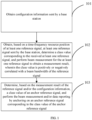
- FIG. 2 is a schematic flowchart of a method for measuring a beam provided by an embodiment of the present disclosure, and the method is performed by the UE. As shown in FIG. 2 , the method for measuring the beam may include steps 201 to 203.
- configuration information sent by a base station is obtained, and the configuration information includes a first target value of a beam quality and a second target value of the beam quality sent by the base station.
- the first target value of the beam quality and the second target value of the beam quality may be preset, and the first target value of the beam quality may be smaller than the second target value of the beam quality.
- At least one reference signal sent by the base station is obtained based on the configuration information, a class value corresponding to the received at least one reference signal is determined, and beam measurement is performed for the at least one reference signal to obtain a measurement result, the class value is negatively correlated with a beam bandwidth of the reference signal.
- step 202 For the detailed introduction about the step 202, reference may be made to the description of the above embodiments, which is not described in details here in embodiments of the present disclosure.
- a class value of an anchor reference signal is determined based on a magnitude relationship between measurement results of reference signals of different classes and the first target value of the beam quality and the second target value of the beam quality, and the beam measurement and/or data reporting are performed by anchoring on the anchor reference signal corresponding to the class value of the anchor reference signal.
- the method of determining the class value of the anchor reference signal based on the magnitude relationship between the measurement results of the reference signals of different classes and the first target value of the beam quality and the second target value of the beam quality can include the following criterions.
- Criterion 1 if there is a first reference signal among all reference signals whose measurement result is greater than or equal to the first target value of the beam quality and smaller than the second target value of the beam quality, a class value of the first reference signal is selected as the class value of the anchor reference signal.
- the first reference signal may include one or more reference signals.
- the class value of the first reference signal with the better beam quality may be directly selected as the class value of the anchor reference signal. In this case, when the beam measurement and/or the data reporting is subsequently performed on the anchor reference signal corresponding to the class value of the anchor reference signal, the beam measurement quality can be ensured.
- the smallest class value in the first reference signal with the better beam quality may be selected as the class value of the anchor reference signal. Since the class value is negatively correlated with the beam bandwidth, a beam of a reference signal corresponding to the smallest class value in the first reference signal is the widest, that is, the beam quality corresponding to the anchor reference signal is better and the beam bandwidth corresponding to the anchor reference signal is wider. Therefore, when the beam measurements and/or the data reporting are subsequently performed on the beam of the anchor reference signal based on the class value of the anchor reference signal, not only the measurement quality of the beam can be ensured, but also the service quality when the UE is in the moving state can be ensured.
- the reference signal 1 corresponds to a class value of 1
- the reference signal 2 corresponds to a class value of 2
- the reference signal 3 corresponds to a class value of 3.
- a measurement result corresponding to the reference signal 1 is smaller than the first target value of the beam quality
- measurement results corresponding to the reference signal 2 and the reference signal 3 are greater than the first target value of the beam quality and smaller than the second target value of the beam quality.
- class values 1 and 2 may be determined as the class value of the anchor reference signal, or only the class value of 2 may be determined as the class value of the anchor reference signal.
- Criterion 2 if a measurement result of a reference signal with the largest class value is smaller than the first target value of the beam quality, a first operation is performed, and the first operation includes at least one of selecting the largest class value in all the reference signals as the class value of the anchor reference signal, performing cell reselection, or sending a handover request to the base station.
- the class value of the reference signal is negatively correlated with the beam bandwidth in this embodiment, the larger the class value of the reference signal, the narrower the beam bandwidth of the reference signal.
- the beam bandwidth is negatively correlated with the beam quality, that is, a beam quality of a beam with a narrower bandwidth is greater than a beam quality of a beam with a wider bandwidth, and the beam bandwidth is positively correlated with the service quality when the UE is in the moving state, that is, the wider the bandwidth of the beam, the larger the coverage of the beam, the better mobility of the UE that can be supported.
- the UE may select the largest class value in the reference signals as the class value of the anchor reference signal, that is, when the beam qualities of all the reference signals are poor, the class value of the reference signal with the relatively best beam quality among the reference signals with the poor beam qualities is determined as the class value of the anchor reference signal, so as to ensure that when the beam measurement and/or the data reporting are subsequently performed on the anchor reference signal, the measurement quality of the beam can be ensured.
- the UE may also not determine the class value of the anchor reference signal, but directly perform the cell reselection and/or send the handover request to the base station in order to re-obtain a reference signal with a better beam quality.
- Criterion 3 if a measurement result of a reference signal with the smallest class value is greater than or equal to the second target value of the beam quality, the smallest class value in all the reference signals is selected as the class value of the anchor reference signal.
- the class value of the reference signal being negatively correlated with the beam bandwidth
- the measurement result of the reference signal with the smallest class value is greater than or equal to the second target value of the beam quality
- the UE may select the minimum class value in all the reference signals as the class value of the anchor reference signal, that is, when the beam qualities of all the reference signals are good, a class value of a reference signal with the widest beam bandwidth is preferably determined as the class value of the anchor reference signal. Therefore, when the beam measurement and/or the data reporting are subsequently performed on the anchor reference signal corresponding to the class value of the anchor reference signal, the measurement quality of the beam can be ensured, and the service quality when the UE is in the moving state can be ensured.
- the class value corresponding to the reference signal may also be positively correlated with the beam bandwidth.
- the method of determining the class value of the anchor reference signal based on the magnitude relationship between the measurement results of the reference signals of different classes and the first target value of the beam quality and the second target value of the beam quality may include:
- determination criterions for the class value of the anchor reference signal in a case where "the class value corresponding to the reference signal is positively correlated with the beam bandwidth" are the same as those in a case where "the class value corresponding to the reference signal is negatively correlated with the beam bandwidth", which are both that on the premise of ensuring the beam quality, the service quality when the UE is in the moving state is further ensured, which will not be described in details here in embodiments of the present disclosure.
- the UE may obtain the configuration information sent by the base station, and may obtain, based on the configuration information, the at least one reference signal sent by the base station, determine the class value corresponding to the received at least one reference signal, and perform the beam measurement for the at least one reference signal to obtain the measurement result.
- the class value is positively or negatively correlated with the beam bandwidth of the reference signal.
- the UE may determine, based on the measurement result of the reference signal and/or the configuration information, the class value of the anchor reference signal, and perform the beam measurement and/or the data reporting by anchoring on the anchor reference signal corresponding to the class value of the anchor reference signal.
- the UE may determine the class value of the anchor reference signal based on its measurement result for the at least one reference signal sent by the base station and/or the configuration information sent by the base station, and may subsequently perform the beam measurement and/or the data reporting by anchoring on the anchor reference signal corresponding to the class value of the anchor reference signal.
- the embodiments of the present disclosure provide the method for measuring the beam applied to the millimeter wave communication process and/or the terahertz communication process.
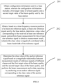
- FIG. 3 is a schematic flowchart of a method for measuring a beam provided by an embodiment of the present disclosure, and the method is performed by the UE. As shown in FIG. 3 , the method for measuring the beam may include steps 301 to 303.
- step 301 configuration information sent by a base station is obtained, and the configuration information includes a class value of an anchor reference signal specified by the base station.
- the class value of the specified anchor reference signal may be determined by the base station.
- At least one reference signal sent by the base station is obtained based on a time-frequency resource position of the at least one reference signal, a class value corresponding to the received at least one reference signal is determined, and beam measurement is performed for the at least one reference signal to obtain a measurement result.
- the class value of the specified anchor reference signal is selected as a class value of an anchor reference signal, and the beam measurement and/or data reporting are performed by anchoring on an anchor reference signal corresponding to the class value of the anchor reference signal.
- the UE obtains the reference signal 1, the reference signal 2 and the reference signal 3, the reference signal 1 corresponds to the class value of 1, the reference signal 2 corresponds to the class value of 2, and the reference signal 3 corresponds to the class value of 3.
- the beam measurement and/or the data reporting may be performed directly on the reference signal 3.
- the UE may obtain the configuration information sent by the base station, and may obtain, based on the configuration information, the at least one reference signal sent by the base station, determine the class value corresponding to the received at least one reference signal, and perform the beam measurement for the at least one reference signal to obtain the measurement result.
- the class value is positively or negatively correlated with the beam bandwidth of the reference signal.
- the UE may determine, based on the measurement result of the reference signal and/or the configuration information, the class value of the anchor reference signal, and perform the beam measurement and/or the data reporting by anchoring on the anchor reference signal corresponding to the class value of the anchor reference signal.
- the UE may determine the class value of the anchor reference signal based on its measurement result for the at least one reference signal sent by the base station and/or the configuration information sent by the base station, and may subsequently perform the beam measurement and/or the data reporting by anchoring on the anchor reference signal corresponding to the class value of the anchor reference signal.
- the embodiments of the present disclosure provide the method for measuring the beam applied to the millimeter wave communication process and/or the terahertz communication process.
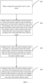
- FIG. 4 is a schematic flowchart of a method for measuring a beam provided by an embodiment of the present disclosure, and the method is performed by the UE. As shown in FIG. 4 , the method for measuring the beam may include steps 401 to 404.
- step 401 configuration information sent by a base station is obtained.
- the configuration information includes at least one of a time-frequency resource position of at least one reference signal for the beam measurement, a first target value of a beam quality, a second target value of the beam quality, a class value of a specified anchor reference signal, a reporting condition of the beam measurement, or a measurement quantity of the beam measurement sent by the base station.
- At least one reference signal sent by the base station is obtained based on a time-frequency resource position of the at least one reference signal, a class value corresponding to the received at least one reference signal is determined, and beam measurement is performed for the at least one reference signal to obtain a measurement result, the class value is negatively correlated with a beam bandwidth of the reference signal.
- a class value of an anchor reference signal is determined based on a measurement result of the reference signal and/or the configuration information, and the beam measurement and/or data reporting are performed by anchoring on an anchor reference signal corresponding to the class value of the anchor reference signal.
- the class value of the anchor reference signal is updated according to a measurement result of the anchor reference signal, and the beam measurement and/or the data reporting are performed by anchoring on an updated anchor reference signal corresponding to the updated class value of the anchor reference signal.
- the beam quality of the anchor reference signal may change due to some reasons (such as the movement of the UE). In this case, it is necessary to update the anchor reference signal according to the measurement result of the anchor reference signal.
- the method of updating the class value of the anchor reference signal according to the measurement result of the anchor reference signal may include:
- the class value of the anchor reference signal is updated, and the class value of the anchor reference signal after the update is smaller than the class value of the anchor reference signal before the update. If the measurement result of the anchor reference signal is smaller than the first target value of the beam quality, the class value of the anchor reference signal is updated, and the class value of the anchor reference signal after the update is greater than the class value of the anchor reference signal before the update.
- the anchor reference signal when the measurement result of the anchor reference signal is greater than or equal to the second target value of the beam quality, it indicates that the beam qualities of all the current reference signals are better than before.
- the anchor reference signal may be updated to a reference signal with a smaller class value, that is, the class value of the anchor reference signal after the update is smaller than the class value of the anchor reference signal before the update. Then, based on the class value of the reference signal being negatively correlated with the beam bandwidth, the beam bandwidth of the anchor reference signal after the update is greater than the beam bandwidth of the anchor reference signal before the update.
- the anchor reference signal when the measurement result of the anchor reference signal is smaller than the first target value of the beam quality, it indicates that the beam qualities of all the current reference signals are worse than before.
- the anchor reference signal since the beam quality of the reference signal with the narrower beam bandwidth is greater than the beam quality of the reference signal with the wider beam bandwidth, the anchor reference signal may be updated to a reference signal with a larger class value, that is, the class value of the anchor reference signal after the update is greater than the class value of the anchor reference signal before the update.
- the beam bandwidth of the anchor reference signal after the update is smaller than the beam bandwidth of the anchor reference signal before the update, that is, the beam quality of the anchor reference signal after the update is higher than the beam quality of the anchor reference signal before the update.
- the UE obtains the reference signal 1, the reference signal 2, and the reference signal 3 sent by the base station, the class value of the reference signal 1 is 1, the class value of the reference signal 2 is 2, the class value of the reference signal 3 is 3, and the anchor reference signal is the reference signal 2. If it is detected that the anchor reference signal is greater than or equal to the second target value of the beam quality, the reference signal 1 may be determined as the updated anchor reference signal. If it is detected that the anchor reference signal is smaller than the first target value of the beam quality, the reference signal 3 may be determined as the updated anchor reference signal.
- the method of performing the data reporting by anchoring on the anchor reference signal corresponding to the updated class value of the anchor reference signal may include:
- only data that meets the reporting condition of the beam measurement may be reported to the base station.
- the class value corresponding to the reference signal may also be positively correlated with the beam bandwidth.
- the method of updating the anchor reference signal based on the magnitude relationship between the measurement result of the anchor reference signal and the first target value of the beam quality and the second target value of the beam quality may include:
- update criterions for the class value of the anchor reference signal in a case where "the class value corresponding to the reference signal is positively correlated with the beam bandwidth" are similar to update criterions in a case where "the class value corresponding to the reference signal is negatively correlated with the beam bandwidth", which are both that on the premise of ensuring the beam quality, the service quality when the UE is in the moving state is further ensured, which is not described in details here in embodiments of the present disclosure.
- the UE may obtain the configuration information sent by the base station, and may obtain, based on the configuration information, the at least one reference signal sent by the base station, determine the class value corresponding to the received at least one reference signal, and perform the beam measurement for the at least one reference signal to obtain the measurement result.
- the class value is positively or negatively correlated with the beam bandwidth of the reference signal.
- the UE may determine, based on the measurement result of the reference signal and/or the configuration information, the class value of the anchor reference signal, and perform the beam measurement and/or the data reporting by anchoring on the anchor reference signal corresponding to the class value of the anchor reference signal.
- the UE may determine the class value of the anchor reference signal based on its measurement result for the at least one reference signal sent by the base station and/or the configuration information sent by the base station, and may subsequently perform the beam measurement and/or the data reporting by anchoring on the anchor reference signal corresponding to the class value of the anchor reference signal.
- the embodiments of the present disclosure provide the method for measuring the beam applied to the millimeter wave communication process and/or the terahertz communication process.
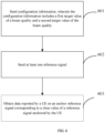
- FIG. 5 is a schematic flowchart of a method for measuring a beam provided by an embodiment of the present disclosure, and the method is performed by the base station. As shown in FIG. 5 , the method for measuring the beam may include steps 501 to 503.
- step 501 configuration information is sent.
- the configuration information may include at least one of a time-frequency resource position of at least one reference signal for the beam measurement, a first target value of a beam quality, a second target value of the beam quality, a class value of a specified anchor reference signal, a reporting condition of the beam measurement, or a measurement quantity of the beam measurement sent by the base station.
- the measurement quantity of the beam measurement includes at least one of:
- the method for the base station to send the configuration information to the UE may include:
- the base station may also first determine a time-frequency resource position of the reference signal used for the beam measurement.
- determining the time-frequency resource position of the reference signal for the beam measurement may include the following steps:
- step 502 at least one reference signal is sent.
- the base station may send the at least one reference signal to the UE based on the time domain resource position determined in the step 501.
- the at least one reference signal has a corresponding class value, and the class value is positively or negatively correlated with the beam bandwidth of the reference signal.
- step 504 data reported by the UE is obtained on an anchor reference signal corresponding to a class value of a reference signal anchored by the UE.
- the method of obtaining the data reported by the UE includes at least one of:
- the UE may obtain the configuration information sent by the base station, and may obtain, based on the configuration information, the at least one reference signal sent by the base station, determine the class value corresponding to the received at least one reference signal, and perform the beam measurement for the at least one reference signal to obtain the measurement result.
- the class value is positively or negatively correlated with the beam bandwidth of the reference signal.
- the UE may determine, based on the measurement result of the reference signal and/or the configuration information, the class value of the anchor reference signal, and perform the beam measurement and/or the data reporting by anchoring on the anchor reference signal corresponding to the class value of the anchor reference signal.
- the UE may determine the class value of the anchor reference signal based on its measurement result for the at least one reference signal sent by the base station and/or the configuration information sent by the base station, and may subsequently perform the beam measurement and/or the data reporting by anchoring on the anchor reference signal corresponding to the class value of the anchor reference signal.
- the embodiments of the present disclosure provide the method for measuring the beam applied to the millimeter wave communication process and/or the terahertz communication process.
- FIG. 6 is a schematic flowchart of a method for measuring a beam provided by an embodiment of the present disclosure, and the method is performed by the base station. As shown in FIG. 6 , the method for measuring the beam may include steps 601 to 603.
- configuration information is sent, and the configuration information includes a first target value of a beam quality and a second target value of the beam quality.
- At least one reference signal is sent, the at least one reference signal has a corresponding class value, and the class value is negatively correlated with a beam bandwidth of the reference signal.
- step 603 data reported by the UE is obtained on an anchor reference signal corresponding to a class value of a reference signal anchored by the UE.
- the UE may obtain the configuration information sent by the base station, and may obtain, based on the configuration information, the at least one reference signal sent by the base station, determine the class value corresponding to the received at least one reference signal, and perform the beam measurement for the at least one reference signal to obtain the measurement result.
- the class value is positively or negatively correlated with the beam bandwidth of the reference signal.
- the UE may determine, based on the measurement result of the reference signal and/or the configuration information, the class value of the anchor reference signal, and perform the beam measurement and/or the data reporting by anchoring on the anchor reference signal corresponding to the class value of the anchor reference signal.
- the UE may determine the class value of the anchor reference signal based on its measurement result for the at least one reference signal sent by the base station and/or the configuration information sent by the base station, and may subsequently perform the beam measurement and/or the data reporting by anchoring on the anchor reference signal corresponding to the class value of the anchor reference signal.
- the embodiments of the present disclosure provide the method for measuring the beam applied to the millimeter wave communication process and/or the terahertz communication process.
- FIG. 7 is a schematic flowchart of a method for measuring a beam provided by an embodiment of the present disclosure, and the method is performed by the base station. As shown in FIG. 7 , the method for measuring the beam may include steps 701 to 703.
- step 701 configuration information is sent, and the configuration information includes a class value of a specified anchor reference signal.
- step 703 data reported by the UE is obtained on an anchor reference signal corresponding to a class value of a reference signal anchored by the UE.
- the UE may obtain the configuration information sent by the base station, and may obtain, based on the configuration information, the at least one reference signal sent by the base station, determine the class value corresponding to the received at least one reference signal, and perform the beam measurement for the at least one reference signal to obtain the measurement result.
- the class value is positively or negatively correlated with the beam bandwidth of the reference signal.
- the UE may determine, based on the measurement result of the reference signal and/or the configuration information, the class value of the anchor reference signal, and perform the beam measurement and/or the data reporting by anchoring on the anchor reference signal corresponding to the class value of the anchor reference signal.
- the UE may determine the class value of the anchor reference signal based on its measurement result for the at least one reference signal sent by the base station and/or the configuration information sent by the base station, and may subsequently perform the beam measurement and/or the data reporting by anchoring on the anchor reference signal corresponding to the class value of the anchor reference signal.
- the embodiments of the present disclosure provide the method for measuring the beam applied to the millimeter wave communication process and/or the terahertz communication process.
- FIG. 8 is a schematic flowchart of a method for measuring a beam provided by an embodiment of the present disclosure, and the method is performed by the base station. As shown in FIG. 8 , the method for measuring the beam may include steps 801 to 804.
- At least one reference signal is sent, the at least one reference signal has a corresponding class value, and the class value is negatively correlated with a beam bandwidth of the reference signal.
- step 803 data reported by the UE is obtained on an anchor reference signal corresponding to a class value of a reference signal anchored by the UE.
- step 804 updated data reported by the UE is obtained on an updated anchor reference signal corresponding to the class value of the reference signal anchored in an updated manner by the UE.
- the method of obtaining the updated data reported by the UE may include at least one of:
- the UE may obtain the configuration information sent by the base station, and may obtain, based on the configuration information, the at least one reference signal sent by the base station, determine the class value corresponding to the received at least one reference signal, and perform the beam measurement for the at least one reference signal to obtain the measurement result.
- the class value is positively or negatively correlated with the beam bandwidth of the reference signal.
- the UE may determine, based on the measurement result of the reference signal and/or the configuration information, the class value of the anchor reference signal, and perform the beam measurement and/or the data reporting by anchoring on the anchor reference signal corresponding to the class value of the anchor reference signal.
- the UE may determine the class value of the anchor reference signal based on its measurement result for the at least one reference signal sent by the base station and/or the configuration information sent by the base station, and may subsequently perform the beam measurement and/or the data reporting by anchoring on the anchor reference signal corresponding to the class value of the anchor reference signal.
- the embodiments of the present disclosure provide the method for measuring the beam applied to the millimeter wave communication process and/or the terahertz communication process.
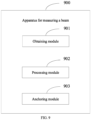
- FIG. 9 is a schematic structural diagram of an apparatus 900 for measuring a beam provided by an embodiment of the present disclosure, and the method is performed by the UE. As shown in FIG. 9 , the method for measuring the beam may include the following steps:
- the UE may obtain the configuration information sent by the base station, and may obtain, based on the configuration information, the at least one reference signal sent by the base station, determine the class value corresponding to the received at least one reference signal, and perform the beam measurement for the at least one reference signal to obtain the measurement result.
- the class value is positively or negatively correlated with the beam bandwidth of the reference signal.
- the UE may determine, based on the measurement result of the reference signal and/or the configuration information, the class value of the anchor reference signal, and perform the beam measurement and/or the data reporting by anchoring on the anchor reference signal corresponding to the class value of the anchor reference signal.
- the UE may determine the class value of the anchor reference signal based on its measurement result for the at least one reference signal sent by the base station and/or the configuration information sent by the base station, and may subsequently perform the beam measurement and/or the data reporting by anchoring on the anchor reference signal corresponding to the class value of the anchor reference signal.
- the embodiments of the present disclosure provide the method for measuring the beam applied to the millimeter wave communication process and/or the terahertz communication process.
- the configuration information includes at least one of a time-frequency resource position of the at least one reference signal for the beam measurement, a first target value of a beam quality, a second target value of the beam quality, a class value of a specified anchor reference signal, a reporting condition of the beam measurement, or a measurement quantity of the beam measurement sent by the base station.
- the processing module is further configured to: obtain, based on the time-frequency resource position of the at least one reference signal, the at least one reference signal sent by the base station.
- the processing module is further configured to:
- the anchoring module is further configured to: determine the class value of the anchor reference signal based on a magnitude relationship between measurement results of reference signals of different classes and the first target value of the beam quality and the second target value of the beam quality.
- the class value is negatively correlated with the beam bandwidth of the reference signal
- the anchoring module is further configured to:
- the class value is positively correlated with the beam bandwidth of the reference signal
- the anchoring module is further configured to:
- the anchoring module is further configured to: select the class value of the specified anchor reference signal as the class value of the anchor reference signal.
- the anchoring module is further configured to:
- the apparatus is further configured to: update the class value of the anchor reference signal according to a measurement result of the anchor reference signal, and perform the beam measurement and/or the data reporting by anchoring on an updated anchor reference signal corresponding to the updated class value of the anchor reference signal.
- the apparatus is further configured to: update the anchor reference signal based on a magnitude relationship between the measurement result of the anchor reference signal and a first target value of a beam quality and a second target value of the beam quality.
- the class value is negatively correlated with the beam bandwidth of the reference signal, and the apparatus is further configured to:
- the class value is positively correlated with the beam bandwidth of the reference signal, and the apparatus is further configured to:
- the apparatus is further configured to:
- the measurement quantity of the beam measurement includes at least one of:
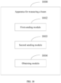
- FIG. 10 is a schematic structural diagram of an apparatus 1000 for measuring a beam provided by an embodiment of the present disclosure, and the method is performed by the base station. As shown in FIG. 10 , the method for measuring the beam may include the following steps:
- the UE may obtain the configuration information sent by the base station, and may obtain, based on the configuration information, the at least one reference signal sent by the base station, determine the class value corresponding to the received at least one reference signal, and perform the beam measurement for the at least one reference signal to obtain the measurement result.
- the class value is positively or negatively correlated with the beam bandwidth of the reference signal.
- the UE may determine, based on the measurement result of the reference signal and/or the configuration information, the class value of the anchor reference signal, and perform the beam measurement and/or the data reporting by anchoring on the anchor reference signal corresponding to the class value of the anchor reference signal.
- the UE may determine the class value of the anchor reference signal based on its measurement result for the at least one reference signal sent by the base station and/or the configuration information sent by the base station, and may subsequently perform the beam measurement and/or the data reporting by anchoring on the anchor reference signal corresponding to the class value of the anchor reference signal.
- the embodiments of the present disclosure provide the method for measuring the beam applied to the millimeter wave communication process and/or the terahertz communication process.
- the configuration information includes at least one of a time-frequency resource position of the at least one reference signal for the beam measurement, a first target value of a beam quality, a second target value of the beam quality, a class value of a specified anchor reference signal, a reporting condition of the beam measurement, or a measurement quantity of the beam measurement sent by the base station.
- the apparatus is further configured to:
- the first sending module is further configured to: send the configuration information to the UE through a signaling.
- the obtaining module is further configured to:
- the apparatus is further configured to: obtain updated data reported by the UE on an updated anchor reference signal corresponding to a class value of a reference signal anchored in an updated manner by the UE.
- the apparatus is further configured to:
- the measurement quantity of the beam measurement includes at least one of:
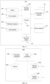
- FIG. 11 is a block diagram of a User Equipment (UE) 1100 provided by an embodiment of the present disclosure.
- the UE 1100 may be a mobile phone, a computer, a digital broadcast terminal device, a messaging device, a gaming console, a tablet, a medical device, an exercise device, a personal digital assistant, etc.
- the UE 1100 may include at least one of the following components: a processing component 1102, a memory 1104, a power component 1106, a multimedia component 1108, an audio component 1110, an input/output (I/O) interface 1112, a sensor component 1113, and a communication component 1116.
- a processing component 1102 a memory 1104, a power component 1106, a multimedia component 1108, an audio component 1110, an input/output (I/O) interface 1112, a sensor component 1113, and a communication component 1116.
- the processing component 1102 typically controls overall operations of the UE 1100, such as the operations associated with display, telephone calls, data communications, camera operations, and recording operations.
- the processing component 1102 may include at least one processor 1120 to execute instructions to perform all or part of the steps in the above described methods.
- the processing component 1102 may include at least one module which facilitate the interaction between the processing component 1102 and other components.
- the processing component 1102 may include a multimedia module to facilitate the interaction between the multimedia component 1108 and the processing component 1102.
- the memory 1104 is configured to store various types of data to support the operation of the UE 1100. Examples of such data include instructions for any applications or methods operated on the UE 1100, contact data, phonebook data, messages, pictures, video, etc.
- the memory 1104 may be implemented using any type of volatile or non-volatile memory apparatuses, or a combination thereof, such as a static random access memory (SRAM), an electrically erasable programmable read-only memory (EEPROM), an erasable programmable read-only memory (EPROM), a programmable read-only memory (PROM), a read-only memory (ROM), a magnetic memory, a flash memory, a magnetic or optical disk.
- SRAM static random access memory
- EEPROM electrically erasable programmable read-only memory
- EPROM erasable programmable read-only memory
- PROM programmable read-only memory
- ROM read-only memory
- magnetic memory a magnetic memory
- flash memory a flash memory
- the power component 1106 provides power to various components of the UE 1100.
- the power component 1106 may include a power management system, at least one power source, and any other components associated with the generation, management, and distribution of power in the UE 1100.
- the multimedia component 1108 includes a screen providing an output interface between the UE 1100 and the user.
- the screen may include a liquid crystal display (LCD) and a touch panel (TP). If the screen includes the touch panel, the screen may be implemented as a touch screen to receive input signals from the user.
- the touch panel includes at least one touch sensor to sense touches, swipes, and gestures on the touch panel. The touch sensors may not only sense a boundary of a touch or swipe action, but also sense a wake-up time and a pressure associated with the touch or swipe action.
- the multimedia component 1108 includes a front camera and/or a rear camera.
- the front camera and the rear camera may receive an external multimedia datum while the UE 1100 is in an operation mode, such as a photographing mode or a video mode.
- an operation mode such as a photographing mode or a video mode.
- Each of the front camera and the rear camera may be a fixed optical lens system or have focus and optical zoom capability.
- the audio component 1110 is configured to output and/or input audio signals.
- the audio component 1110 includes a microphone (MIC) configured to receive an external audio signal when the UE 1100 is in an operation mode, such as a call mode, a recording mode, and a voice recognition mode.
- the received audio signal may be further stored in the memory 1104 or transmitted via the communication component 1116.
- the audio component 1110 further includes a speaker to output audio signals.
- the I/O interface 1112 provides an interface between the processing component 1102 and peripheral interface modules, such as a keyboard, a click wheel, buttons, and the like.
- the buttons may include, but are not limited to, a home button, a volume button, a starting button, and a locking button.
- the sensor component 1113 includes at least one sensor to provide state assessments of various aspects of the UE 1100. For instance, the sensor component 1113 may detect an open/closed state of the UE 1100, relative positioning of components, e.g., the display and the keypad, of the UE 1100, a change in position of the UE 1100 or a component of the UE 1100, a presence or absence of user contact with the UE 1100, an orientation or an acceleration/deceleration of the UE 1100, and a change in temperature of the UE 1100.
- the sensor component 1113 may include a proximity sensor configured to detect the presence of nearby objects without any physical contact.
- the sensor component 1113 may further include a light sensor, such as a CMOS or CCD image sensor, for use in imaging applications.
- the sensor component 1113 may further include an accelerometer sensor, a gyroscope sensor, a magnetic sensor, a pressure sensor, or a temperature sensor.
- the communication component 1116 is configured to facilitate communication, wired or wirelessly, between the UE 1100 and other devices.
- the UE 1100 may access a wireless network based on a communication standard, such as WiFi, 2G, or 3G, or a combination thereof.
- the communication component 1116 receives a broadcast signal or broadcast associated information from an external broadcast management system via a broadcast channel.
- the communication component 1116 further includes a near field communication (NFC) module to facilitate short-range communications.
- the NFC module may be implemented based on a radio frequency identification (RFID) technology, an infrared data association (IrDA) technology, an ultra-wideband (UWB) technology, a Bluetooth (BT) technology, and other technologies.
- RFID radio frequency identification
- IrDA infrared data association
- UWB ultra-wideband
- BT Bluetooth
- the UE 1100 may be implemented with at least one application specific integrated circuit (ASIC), digital signal processor (DSP), digital signal processing device (DSPD), programmable logic device (PLD), field programmable gate array (FPGA), controller, micro-controller, microprocessor, or other electronic components, for performing the above described methods.
- ASIC application specific integrated circuit
- DSP digital signal processor
- DSPD digital signal processing device
- PLD programmable logic device
- FPGA field programmable gate array
- controller micro-controller, microprocessor, or other electronic components, for performing the above described methods.
- FIG. 12 is a block diagram of a network side device 1200 provided by an embodiment of the present disclosure.
- the network side device 1200 may be provided as a network device.
- the network side device 1200 includes a processing component 1211, which further includes at least one processor and a memory resource represented by a memory 1232 for storing instructions executable by the processing component 1222, such as an application program.
- the application program stored in the memory 1232 may include one or more modules, each corresponding to a set of instructions.
- the processing component 1210 is configured to execute the instructions to execute the aforementioned any method applied on the network side device, for example, the method shown in FIG. 1 .
- the network side device 1200 may further include: a power component 1226 configured to perform power management of the network side device 1200, a wired or wireless network interface 1250 configured to connect the network side device 1200 to the network, and an input/output (I/O) interface 1258.
- the network side device 1200 may operate an operating system stored in the memory 1232, such as Windows Server TM, Mac OS XTM, UnixTM, LinuxTM, FreeBSDTM, or the like.
- the methods provided by embodiments of the present disclosure are introduced from the perspectives of the network side device and the UE.
- the network side device and the UE may include hardware structures and software modules, and the various functions are implemented in the form of hardware structures, software modules, or hardware structures plus software modules.
- One of the various functions may be implemented in the form of hardware structures, software modules, or hardware structure plus software modules.
- Embodiments of the present disclosure provide a communication device.
- the communication device may include a transceiver module and a processing module.
- the transceiver module may include a transmitting module and/or a receiving module.
- the transmitting module is configured to implement a transmission function
- the receiving module is configured to implement a reception function.
- the transceiver module may implement the transmission function and/or the reception function.
- the communication device may be a terminal device (such as the terminal device in the above method embodiments), a device in the terminal device, or a device that can be used in conjunction with the terminal device.
- the communication device may be a network device, a device in the network device, or a device that can be used in conjunction with the network device.
- Embodiments of the present disclosure provide another communication device.
- the communication device may be a network device, or may be a terminal device (such as the terminal device in the above method embodiments), or may be a chip, a chip system, a processor or the like that supports the network device to implement the above method, or may be a chip, a chip system, a processor or the like that supports the terminal device to implement the above method.
- the device can be used to implement the method described in the above method embodiments. For details, reference may be made to the description in the above method embodiments.
- the communication device may include one or more processors.
- the processor may be a general-purpose processor or a dedicated processor, or the like.
- the processor may be a baseband processor or a central processing unit.
- the baseband processor can be used to process communication protocols and communication data.
- the central processor can be used to control the communication devices (such as network side devices, baseband chips, terminal devices, terminal device chips, DU or CU, or the like), execute computer programs, and process data for the computer programs.
- the communication device may further include one or more memories, on which a computer program may be stored.
- the processor executes the computer program, so that the communication device performs the method described in the above method embodiments.
- the memory may also store data. The communication device and the memory can be provided separately or integrated together.
- the communication device may further include a transceiver and an antenna.
- the transceiver may be referred to as a transceiver unit, a transceiver, a transceiver circuit, or the like, and is used to implement transceiver functions.
- the transceiver may include a receiver and a transmitter.
- the receiver may be referred to as a receiver or a receiving circuit, or the like, and is used to implement the receiving function; and the transmitter may be referred to as a transmitter, a transmitting circuit, or the like, and is used to implement the transmitting function.
- the communication device may further include one or more interface circuits.
- the interface circuit is used to receive code instructions and transmit the code instructions to the processor.
- the processor executes the code instructions to cause the communication device to perform the method described in the above method embodiments.
- the communication device is a terminal device (such as the terminal device in the foregoing method embodiments), and the processor is configured to execute the method shown in any one of FIGS. 1-4 .
- the communication device is a network device, and the transceiver is configured to execute the method shown in any one of FIGS. 5-7 .
- the processor may include a transceiver for implementing receiving and transmitting functions.
- the transceiver may be a transceiver circuit, an interface, or an interface circuit.
- the transceiver circuits, interfaces or interface circuits used to implement the receiving and transmitting functions can be separate or integrated together.
- the above-mentioned transceiver circuit, interface or interface circuit can be used for reading and writing codes/data, or the above-mentioned transceiver circuit, interface or interface circuit can be used for signal transmission or transfer.
- the processor may be stored with a computer program, and the computer program is executed by the processor, causing the communication device to perform the method described in the above method embodiments.
- the computer program may be solidified in the processor, in which case the processor may be implemented by hardware.
- the communication device may include a circuit, and the circuit may implement the functions of sending or receiving or communicating in the foregoing method embodiments.
- the processors and transceivers described in the present disclosure may be implemented on an integrated circuit (IC), an analog IC, a radio frequency integrated circuit (RFIC), a mixed signal IC, an application specific integrated circuit (ASIC), a printed circuit boards (PCB), an electronic device, and the like.
- the processor and transceiver can also be manufactured using various IC process technologies, such as complementary metal oxide semiconductor (CMOS), N-type metal oxide semiconductor (nMetal-oxide-semiconductor, NMOS), P-type metal oxide semiconductor (positive channel metal oxide semiconductor, PMOS), bipolar junction transistor (BJT), bipolar CMOS (BiCMOS), silicon germanium (SiGe), gallium arsenide (GaAs), and the like.
- CMOS complementary metal oxide semiconductor
- N-type metal oxide semiconductor nMetal-oxide-semiconductor
- PMOS positive channel metal oxide semiconductor
- BJT bipolar junction transistor
- BiCMOS bipolar CMOS
- SiGe silicon germanium
- GaAs gallium arsenide
- the communication device described in the above embodiments may be the network device or the terminal device (e.g., the terminal device in the above method embodiments), but the scope of the communication device described in the present disclosure is not limited thereto, and the structure of the communication device may not be limited.
- the communication device may be a stand-alone device or may be part of a larger device.
- the communication device may be:
- the communication device may be a chip or a system on a chip
- the chip includes a processor and an interface.
- the number of processors may be one or more, and the number of interfaces may be multiple.
- the chip further includes a memory, and the memory is configured to store necessary computer programs and data.
- Embodiments of the present disclosure further provide a system for determining a sidelink duration.
- the system includes the communication device as the terminal device (such as the first terminal device in the above method embodiments) and the communication device as the network device in the above embodiments, or the system includes the communication device as the terminal device (such as the first terminal device in the above method embodiments) and the communication device as the network device in the above embodiments.
- the present disclosure further provides a readable storage medium on which instructions are stored. When the instructions are executed by a computer, the functions of any of the above method embodiments are implemented.
- the present disclosure further provides a computer program product, which, when been executed by a computer, implements the functions of any of the above method embodiments.
- the above embodiments it may be implemented in whole or in part by software, hardware, firmware, or any combination thereof.
- software it may be implemented in whole or in part in the form of a computer program product.
- the computer program product includes one or more computer programs.
- the computer program When the computer program is loaded and executed on a computer, the processes or functions described in accordance with the embodiments of the present disclosure are generated in whole or in part.
- the computer may be a general-purpose computer, a dedicated computer, a computer network, or other programmable device.
- the computer program may be stored in a computer-readable storage medium, or been transferred from one computer-readable storage medium to another, for example, the computer program may be transferred from a website, computer, server, or data center to another website, computer, server or data center via wired (such as coaxial cable, optical fiber, digital subscriber line (DSL)) or wireless (such as infrared, wireless, microwave, or the like) means.
- the computer-readable storage medium may be any available medium that can be accessed by a computer, or a data storage device such as an integrated server, data center, or the like, that includes one or more available media.
- the available media may be magnetic media (e.g., floppy disks, hard disks, magnetic tapes), optical media (e.g., high-density digital video discs (DVD)), or semiconductor media (e.g., solid state disks, SSD)) or the like.
- magnetic media e.g., floppy disks, hard disks, magnetic tapes
- optical media e.g., high-density digital video discs (DVD)
- DVD digital video discs
- semiconductor media e.g., solid state disks, SSD
- At least one in the present disclosure can also be described as one or more, and the plurality can be two, three, four or more, which is not limited in the present disclosure.
- first”, “second”, “third”, “A”, “B”, “C” and “D”, or the like are used to distinguish the technical features in the type of technical feature, and the technical features described with “first”, “second”, “third”, “A”, “B”, “C” and “D” are in no order of precedence or order of size.
Landscapes
- Engineering & Computer Science (AREA)
- Signal Processing (AREA)
- Computer Networks & Wireless Communication (AREA)
- Quality & Reliability (AREA)
- Physics & Mathematics (AREA)
- Electromagnetism (AREA)
- Mobile Radio Communication Systems (AREA)
Applications Claiming Priority (1)
| Application Number | Priority Date | Filing Date | Title |
|---|---|---|---|
| PCT/CN2021/130748 WO2023082279A1 (fr) | 2021-11-15 | 2021-11-15 | Procédé et appareil de mesure de faisceau, équipement utilisateur, dispositif de réseau et support de stockage |
Publications (2)
| Publication Number | Publication Date |
|---|---|
| EP4436070A1 true EP4436070A1 (fr) | 2024-09-25 |
| EP4436070A4 EP4436070A4 (fr) | 2025-01-15 |
Family
ID=86335020
Family Applications (1)
| Application Number | Title | Priority Date | Filing Date |
|---|---|---|---|
| EP21963725.3A Pending EP4436070A4 (fr) | 2021-11-15 | 2021-11-15 | Procédé et appareil de mesure de faisceau, équipement utilisateur, dispositif de réseau et support de stockage |
Country Status (4)
| Country | Link |
|---|---|
| US (1) | US20250031078A1 (fr) |
| EP (1) | EP4436070A4 (fr) |
| CN (1) | CN118104157A (fr) |
| WO (1) | WO2023082279A1 (fr) |
Family Cites Families (5)
| Publication number | Priority date | Publication date | Assignee | Title |
|---|---|---|---|---|
| WO2017184865A1 (fr) * | 2016-04-20 | 2017-10-26 | Convida Wireless, Llc | Signaux de référence configurables |
| US10512046B2 (en) * | 2016-06-09 | 2019-12-17 | Samsung Electronics Co., Ltd. | Method and apparatus for measurement reference signal and synchronization |
| US10278227B2 (en) * | 2017-09-01 | 2019-04-30 | Google Llc | Downlink-only fifth generation new radio |
| CN113383607A (zh) * | 2019-02-14 | 2021-09-10 | 瑞典爱立信有限公司 | 随机接入过程 |
| WO2020205406A1 (fr) * | 2019-03-29 | 2020-10-08 | Apple Inc. | Activation de nouvelle cellule secondaire radio à informations d'état de canal à faisceau fin |
-
2021
- 2021-11-15 EP EP21963725.3A patent/EP4436070A4/fr active Pending
- 2021-11-15 CN CN202180103212.0A patent/CN118104157A/zh active Pending
- 2021-11-15 US US18/708,865 patent/US20250031078A1/en active Pending
- 2021-11-15 WO PCT/CN2021/130748 patent/WO2023082279A1/fr not_active Ceased
Also Published As
| Publication number | Publication date |
|---|---|
| CN118104157A (zh) | 2024-05-28 |
| WO2023082279A1 (fr) | 2023-05-19 |
| EP4436070A4 (fr) | 2025-01-15 |
| US20250031078A1 (en) | 2025-01-23 |
Similar Documents
| Publication | Publication Date | Title |
|---|---|---|
| US12520212B2 (en) | Cell reselection method, cell reselection apparatus, and storage medium | |
| CN115769644A (zh) | 定位辅助终端设备的重新选择方法、装置 | |
| EP4614894A1 (fr) | Procédés et appareils de détermination de mode de positionnement | |
| US20250324308A1 (en) | Reporting method and apparatus | |
| WO2023245589A1 (fr) | Procédé et appareil de détermination de modèle de positionnement | |
| US20250071586A1 (en) | Reference signal measurement method and apparatus, user equipment, network side device and storage medium | |
| US20250280345A1 (en) | Method for recording relevant information of successful pscell addition or change report | |
| US20250287274A1 (en) | Method and apparatus for recording location information for report of successful pscell addition or change | |
| WO2023000178A1 (fr) | Procédé et appareil de réception de signal, équipement utilisateur, station de base et support de stockage | |
| US20250300707A1 (en) | Method for determining ai beam model, device, and storage medium | |
| EP4436070A1 (fr) | Procédé et appareil de mesure de faisceau, équipement utilisateur, dispositif de réseau et support de stockage | |
| EP4412099A1 (fr) | Procédé et appareil d'envoi de rapport, et équipement utilisateur, dispositif côté réseau et support de stockage | |
| US20250015880A1 (en) | Information updating method and apparatus, user equipment, base station, and storage medium | |
| US20250193049A1 (en) | Channel estimation method, apparatus, device, and storage medium | |
| US20250088885A1 (en) | Measurement relaxation method and device | |
| CN117280728B (zh) | 一种测量指示方法及设备/存储介质/装置 | |
| US20250324386A1 (en) | Ranging/sidelink positioning method and apparatus | |
| US20250324463A1 (en) | Cross-ssb-supporting multi-prach transmission configuration methods and apparatuses | |
| EP4422283A1 (fr) | Procédé et appareil d'envoi de rapport, et équipement utilisateur, dispositif côté réseau et support de stockage | |
| US20250193050A1 (en) | Channel estimation method, apparatus and device, and storage medium | |
| US20250048450A1 (en) | Threshold determination method and device for contention-free random access (cfra), storage medium, and apparatus | |
| WO2023133694A1 (fr) | Procédé et appareil de relaxation de mesure, support de stockage et dispositif |
Legal Events
| Date | Code | Title | Description |
|---|---|---|---|
| STAA | Information on the status of an ep patent application or granted ep patent |
Free format text: STATUS: THE INTERNATIONAL PUBLICATION HAS BEEN MADE |
|
| PUAI | Public reference made under article 153(3) epc to a published international application that has entered the european phase |
Free format text: ORIGINAL CODE: 0009012 |
|
| STAA | Information on the status of an ep patent application or granted ep patent |
Free format text: STATUS: REQUEST FOR EXAMINATION WAS MADE |
|
| 17P | Request for examination filed |
Effective date: 20240612 |
|
| AK | Designated contracting states |
Kind code of ref document: A1 Designated state(s): AL AT BE BG CH CY CZ DE DK EE ES FI FR GB GR HR HU IE IS IT LI LT LU LV MC MK MT NL NO PL PT RO RS SE SI SK SM TR |
|
| A4 | Supplementary search report drawn up and despatched |
Effective date: 20241212 |
|
| RIC1 | Information provided on ipc code assigned before grant |
Ipc: H04W 36/00 20090101ALI20241206BHEP Ipc: H04L 5/00 20060101ALI20241206BHEP Ipc: H04B 7/08 20060101ALI20241206BHEP Ipc: H04B 7/06 20060101ALI20241206BHEP Ipc: H04B 17/309 20150101AFI20241206BHEP |
|
| DAV | Request for validation of the european patent (deleted) | ||
| DAX | Request for extension of the european patent (deleted) |