EP4436035A1 - Sensorlose temperaturüberwachung - Google Patents
Sensorlose temperaturüberwachung Download PDFInfo
- Publication number
- EP4436035A1 EP4436035A1 EP24165601.6A EP24165601A EP4436035A1 EP 4436035 A1 EP4436035 A1 EP 4436035A1 EP 24165601 A EP24165601 A EP 24165601A EP 4436035 A1 EP4436035 A1 EP 4436035A1
- Authority
- EP
- European Patent Office
- Prior art keywords
- teg
- aircraft
- circuitry
- electric motor
- motor
- Prior art date
- Legal status (The legal status is an assumption and is not a legal conclusion. Google has not performed a legal analysis and makes no representation as to the accuracy of the status listed.)
- Pending
Links
Images


Classifications
-
- H—ELECTRICITY
- H02—GENERATION; CONVERSION OR DISTRIBUTION OF ELECTRIC POWER
- H02P—CONTROL OR REGULATION OF ELECTRIC MOTORS, ELECTRIC GENERATORS OR DYNAMO-ELECTRIC CONVERTERS; CONTROLLING TRANSFORMERS, REACTORS OR CHOKE COILS
- H02P29/00—Arrangements for regulating or controlling electric motors, appropriate for both AC and DC motors
- H02P29/60—Controlling or determining the temperature of the motor or of the drive
-
- H—ELECTRICITY
- H02—GENERATION; CONVERSION OR DISTRIBUTION OF ELECTRIC POWER
- H02K—DYNAMO-ELECTRIC MACHINES
- H02K11/00—Structural association of dynamo-electric machines with electric components or with devices for shielding, monitoring or protection
- H02K11/20—Structural association of dynamo-electric machines with electric components or with devices for shielding, monitoring or protection for measuring, monitoring, testing, protecting or switching
- H02K11/25—Devices for sensing temperature, or actuated thereby
-
- H—ELECTRICITY
- H02—GENERATION; CONVERSION OR DISTRIBUTION OF ELECTRIC POWER
- H02P—CONTROL OR REGULATION OF ELECTRIC MOTORS, ELECTRIC GENERATORS OR DYNAMO-ELECTRIC CONVERTERS; CONTROLLING TRANSFORMERS, REACTORS OR CHOKE COILS
- H02P29/00—Arrangements for regulating or controlling electric motors, appropriate for both AC and DC motors
- H02P29/02—Providing protection against overload without automatic interruption of supply
- H02P29/032—Preventing damage to the motor, e.g. setting individual current limits for different drive conditions
-
- H—ELECTRICITY
- H10—SEMICONDUCTOR DEVICES; ELECTRIC SOLID-STATE DEVICES NOT OTHERWISE PROVIDED FOR
- H10N—ELECTRIC SOLID-STATE DEVICES NOT OTHERWISE PROVIDED FOR
- H10N10/00—Thermoelectric devices comprising a junction of dissimilar materials, i.e. devices exhibiting Seebeck or Peltier effects
- H10N10/10—Thermoelectric devices comprising a junction of dissimilar materials, i.e. devices exhibiting Seebeck or Peltier effects operating with only the Peltier or Seebeck effects
- H10N10/13—Thermoelectric devices comprising a junction of dissimilar materials, i.e. devices exhibiting Seebeck or Peltier effects operating with only the Peltier or Seebeck effects characterised by the heat-exchanging means at the junction
Definitions
- the present disclosure relates to sensor-less temperature monitoring and, in particular, to sensor-less temperature monitoring and energy harvesting using thermoelectric material.
- An electric aircraft is an aircraft powered by electricity. Electric aircraft may provide reductions in environmental effects of aviation, through zero emissions and quieter flights.
- the electricity can be supplied from a variety of sources and by a variety of methods, the most common being batteries.
- the electricity drives electric motors that in turn drive propellers or turbines.
- a motor temperature control system for an electric aircraft.
- the motor temperature control system includes an electric motor, circuitry and a thermoelectric generator (TEG).
- the TEG is disposed in thermal communication with the electric motor.
- the TEG is electrically coupled to the circuitry such that heat generated by the electric motor is converted by the TEG to electrical energy that generates a voltage drop across the circuitry.
- the electric motor drives at least one of aircraft flight controls, aircraft fuel pumps, aircraft oil pumps, aircraft cooling pumps, aircraft landing systems, aircraft cargo management systems and aircraft air management systems.
- the electric motor includes a stator housing on which the TEG is mounted.
- the motor temperature control system further includes an electric load disposed along the circuitry.
- the electric load includes at least one of on-board aircraft sensors, an aircraft direct current (DC) bus and an aircraft battery.
- DC direct current
- the motor temperature control system includes at least one of a current sensor and a voltage sensor disposed along the circuitry and a controller operably coupled to the at least one of the current sensor and the voltage sensor and configured to determine a temperature of the electric motor based on readings of the at least one of the current sensor and the voltage sensor and to adjust an operation of the electric motor in accordance with the temperature.
- the TEG includes one or more TEG generator elements and each of the one or more TEG generator elements includes a hot side to abut the electric motor, a cold side opposite the hot side and a P-N junction electrically coupled to the circuitry and arranged between the hot side and the cold side to generate voltage to be applied to the circuitry in response to a temperature gradient between the hot side and the cold side.
- the TEG includes multiple TEG generator elements in series.
- the TEG includes multiple TEG generator elements in parallel.
- the TEG includes multiple TEG generator elements and multiple switches electrically interposed between the multiple TEG generator elements.
- the multiple switches are independently operable to arrange at least one or more of the multiple TEG generator elements in series and to arrange at least one or more of the multiple TEG generator elements in parallel.
- a motor temperature control system for an electric aircraft.
- the motor temperature control system includes an electric motor disposed on an aircraft to drive at least one of aircraft flight controls, aircraft fuel pumps, aircraft oil pumps, aircraft cooling pumps, aircraft landing systems, aircraft cargo management systems and aircraft air management systems.
- the motor temperature control system further includes circuitry, an electric load disposed along the circuitry, the electric load comprising at least one of on-board aircraft sensors, an aircraft direct current (DC) bus and an aircraft battery and a thermoelectric generator (TEG).
- the TEG is disposed in thermal communication with the electric motor.
- the TEG is electrically coupled to the circuitry such that heat generated by the electric motor is converted by the TEG to electrical energy that generates a voltage drop across the circuitry.
- the electric motor includes a stator housing on which the TEG is mounted.
- the motor temperature control system includes at least one of a current sensor and a voltage sensor disposed along the circuitry and a controller operably coupled to the at least one of the current sensor and the voltage sensor and configured to determine a temperature of the electric motor based on readings of the at least one of the current sensor and the voltage sensor and to adjust an operation of the electric motor in accordance with the temperature.
- the TEG includes one or more TEG generator elements and each of the one or more TEG generator elements includes a hot side to abut the electric motor, a cold side opposite the hot side and a P-N junction electrically coupled to the circuitry and arranged between the hot side and the cold side to generate voltage to be applied to the circuitry in response to a temperature gradient between the hot side and the cold side.
- the TEG includes multiple TEG generator elements in series.
- the TEG includes multiple TEG generator elements in parallel.
- the TEG includes multiple TEG generator elements and multiple switches electrically interposed between the multiple TEG generator elements.
- the multiple switches are independently operable to arrange at least one or more of the multiple TEG generator elements in series and to arrange at least one or more of the multiple TEG generator elements in parallel.
- a method of motor temperature control for an electric aircraft includes operating an electric motor and disposing a thermoelectric generator (TEG) in thermal communication with the electric motor and electrically coupling the TEG to circuitry such that heat generated by the electric motor is converted by the TEG to electrical energy that generates a voltage drop across the circuitry.
- TEG thermoelectric generator
- the method further includes harvesting the electrical energy for operating at least one of on-board aircraft sensors, an aircraft direct current (DC) bus and an aircraft battery.
- DC direct current
- the method further includes sensing at least one of current applied to the circuitry and the voltage drop across the circuitry, determining a temperature of the electric motor based on results of the sensing and adjusting an operation of the electric motor in accordance with the temperature.
- an integral part of an electrified system is the motor and controller along with other components like feedback and monitoring sensors, mechanical connections, etc.
- the motor includes a stator housing, a stator core, a stator winding, a rotor and a shaft and bearing. Torque is generated due to the interaction of rotor flux and stator flux. During torque generation, heat energy is generated due to losses.
- the stator housing is used (for air-cooled motors, the stator housing is the only means of heat dissipation). Conventionally, temperature of the stator housing is measured using a dedicated sensor for monitoring purposes.
- thermoelectric generator TEG
- the TEG material can generate a potential across its terminals when it is exposed to heat generated by the motor. This voltage can be indicative of a temperature of the motor and can be used for other electric systems. When the voltage is indicative of an overheat problem with the motor, mitigation actions can be taken.
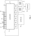
- a motor temperature control system 101 is provided for a fully electric aircraft or for a partially/mostly electric aircraft.
- the motor temperature control system 101 includes an electric motor 110, circuitry 120 and a TEG 130.
- the electric motor 110 includes a stator housing 111, a stator core, a stator winding, a rotor and shaft and bearing.
- the electric motor 110 can be operated to drive operations of at least one of aircraft flight controls 110 1 , aircraft fuel pumps 110 2 , aircraft oil pumps 110s, aircraft cooling pumps 110 4 , aircraft landing systems 110s, aircraft cargo management systems 110 5 and aircraft air management systems 110 6 , etc.
- the electric motor 110 operates, torque for driving the operations listed above is generated due to interactions between rotor flux and stator flux.
- the generation of torque produces heat, which increases a temperature of at least the stator housing 111. While the stator housing 111 can be configured to lose a portion of this heat to surroundings, additional thermal control is necessary and provided by at least the TEG 130.
- the TEG 130 is disposed in thermal communication with the electric motor 110 (i.e., the TEG 130 can be mounted to an exterior surface of the stator housing 111) and is electrically coupled to the circuitry 120.
- a significant portion of the heat generated by the electric motor 110 is converted by the TEG 130 to electrical energy. This electrical energy generates a voltage drop across the circuitry 120, which can serve to cool the electric motor 110, and can be sensed to determine a temperature of the electric motor 110 for mitigation actions.
- a voltage drop associated with the TEG 130 increases generally linearly with exposure to increased heat, such as the heat generated by the electric motor 110.
- the motor temperature control system 101 further includes an electric load 140 disposed along the circuitry 120.
- the electric load 140 can include at least one of on-board aircraft sensors, an aircraft direct current (DC) bus and an aircraft battery. In any case, the electric load 140 can be electrically powered by the electrical energy generated by the TEG 130.
- the motor temperature control system 110 can also include at least one of a current sensor 150 and a voltage sensor 151 disposed along the circuitry 120 as well as a controller 152.
- This controller 152 can be operably coupled to the at least one of the current sensor 150 and the voltage sensor 151 and can be configured to determine a temperature of the electric motor 110 based on readings of the at least one of the current sensor 150 and the voltage sensor 151 and to adjust an operation of the electric motor 110 in accordance with the temperature.
- the controller 152 can shut down the electric motor 110 via a switch or relay.
- the controller 152 can adjust a duty cycle of the electric motor 110 via a proportional integral (PI) controller or another similar device.
- PI proportional integral
- the TEG 130 includes one or more TEG generator elements 131.
- Each of the one or more TEG generator elements 131 includes a hot side 132 to abut the electric motor 110 (i.e., to be mounted to the exterior surface of the stator housing 111), a cold side 133 opposite the hot side 132 and a P-N junction 134.
- the P-N junction 134 is electrically coupled to the circuitry 120 and is arranged between the hot side 132 and the cold side 133 to generate a voltage to be applied to the circuitry 120 in response to a temperature gradient between the hot side 132 and the cold side 133.
- the TEG 130 can include multiple TEG generator elements 131 that are arranged in series along the circuitry 120. As shown in FIG. 3 , the TEG 130 can include multiple TEG generator elements 131 that are arranged in parallel along the circuitry 120. As shown in FIG. 4 , the TEG 130 can include multiple TEG generator elements 131 and multiple switches 135. The multiple switches 135 are electrically interposed between the multiple TEG generator elements 131. The multiple switches 135 can be independently operable to arrange at least one or more of the multiple TEG generator elements 131 in series and to arrange at least one or more of the multiple TEG generator elements 131 in parallel.
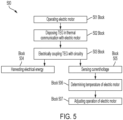
- a method 500 of motor temperature control for an electric aircraft includes operating an electric motor (block 501) and disposing a TEG in thermal communication with the electric motor (block 502) and electrically coupling the TEG to circuitry (block 503) such that heat generated by the electric motor is converted by the TEG to electrical energy that generates a voltage drop across the circuitry.
- the method 500 can further include harvesting the electrical energy for operating at least one of on-board aircraft sensors, an aircraft direct current (DC) bus and an aircraft battery (block 504).
- DC direct current
- the method 500 can include sensing at least one of current applied to the circuitry and the voltage drop across the circuitry (block 505), determining a temperature of the electric motor based on results of the sensing (block 506) and adjusting an operation of the electric motor in accordance with the temperature (block 507).
- any aircraft systems that were powered by the electrical energy generated by the TEG could be affected.
- those affected aircraft systems could receive supplemental power from alternative sources, such as the aircraft DC bus and the aircraft battery, or could be themselves powered down or shut off.
- TEG material for sensor-less motor temperature monitoring to save cost and weight, for improved thermal management and to make available harvested electrical energy that can be used in various systems such as on-board sensors to thereby reduce power consumption of auxiliary supplies.
Landscapes
- Engineering & Computer Science (AREA)
- Power Engineering (AREA)
- Microelectronics & Electronic Packaging (AREA)
- Control Of Electric Motors In General (AREA)
Applications Claiming Priority (1)
| Application Number | Priority Date | Filing Date | Title |
|---|---|---|---|
| IN202311020306 | 2023-03-23 |
Publications (1)
| Publication Number | Publication Date |
|---|---|
| EP4436035A1 true EP4436035A1 (de) | 2024-09-25 |
Family
ID=91247947
Family Applications (1)
| Application Number | Title | Priority Date | Filing Date |
|---|---|---|---|
| EP24165601.6A Pending EP4436035A1 (de) | 2023-03-23 | 2024-03-22 | Sensorlose temperaturüberwachung |
Country Status (3)
| Country | Link |
|---|---|
| US (1) | US12401312B2 (de) |
| EP (1) | EP4436035A1 (de) |
| CA (1) | CA3232469A1 (de) |
Citations (3)
| Publication number | Priority date | Publication date | Assignee | Title |
|---|---|---|---|---|
| US10636725B2 (en) * | 2017-12-19 | 2020-04-28 | Veoneer Us Inc. | Electrical module cooling through waste heat recovery |
| JP2020093706A (ja) * | 2018-12-13 | 2020-06-18 | 三菱重工業株式会社 | モータ一体型ファン及び垂直離着陸機 |
| US20220166368A1 (en) * | 2020-11-23 | 2022-05-26 | Hamilton Sundstrand Corporation | Motor drive electronics using thermoelectric material |
Family Cites Families (9)
| Publication number | Priority date | Publication date | Assignee | Title |
|---|---|---|---|---|
| EP2467686B1 (de) | 2009-08-19 | 2013-05-15 | Siemens Aktiengesellschaft | Anordnung mit einer elektrischen maschine sowie verfahren zum betreiben einer elektrischen maschine |
| US8649179B2 (en) * | 2011-02-05 | 2014-02-11 | Laird Technologies, Inc. | Circuit assemblies including thermoelectric modules |
| US20120204577A1 (en) | 2011-02-16 | 2012-08-16 | Ludwig Lester F | Flexible modular hierarchical adaptively controlled electronic-system cooling and energy harvesting for IC chip packaging, printed circuit boards, subsystems, cages, racks, IT rooms, and data centers using quantum and classical thermoelectric materials |
| US9018878B2 (en) * | 2012-07-23 | 2015-04-28 | Caterpillar Inc. | Derating vehicle electric drive motor and generator components |
| US9459668B2 (en) * | 2013-05-16 | 2016-10-04 | Amazon Technologies, Inc. | Cooling system with desiccant dehumidification |
| EP3386285B1 (de) * | 2015-12-02 | 2021-07-07 | Nec Network And Sensor Systems, Ltd. | Elektronikkomponentengehäusevorrichtung und elektronische vorrichtung |
| US20170252813A1 (en) | 2016-03-03 | 2017-09-07 | Desktop Metal, Inc. | Energy directors for additive fabrication using semi-solid metallic extrusion |
| CN208847348U (zh) | 2018-10-17 | 2019-05-10 | 东方电气集团东方电机有限公司 | 热电发电机集电环温度在线监测装置 |
| WO2020166363A1 (ja) | 2019-02-15 | 2020-08-20 | 株式会社Kelk | 熱電発電装置及び振動検出システム |
-
2023
- 2023-05-22 US US18/321,057 patent/US12401312B2/en active Active
-
2024
- 2024-03-19 CA CA3232469A patent/CA3232469A1/en active Pending
- 2024-03-22 EP EP24165601.6A patent/EP4436035A1/de active Pending
Patent Citations (3)
| Publication number | Priority date | Publication date | Assignee | Title |
|---|---|---|---|---|
| US10636725B2 (en) * | 2017-12-19 | 2020-04-28 | Veoneer Us Inc. | Electrical module cooling through waste heat recovery |
| JP2020093706A (ja) * | 2018-12-13 | 2020-06-18 | 三菱重工業株式会社 | モータ一体型ファン及び垂直離着陸機 |
| US20220166368A1 (en) * | 2020-11-23 | 2022-05-26 | Hamilton Sundstrand Corporation | Motor drive electronics using thermoelectric material |
Non-Patent Citations (1)
| Title |
|---|
| LEE JOEL ET AL: "High-Endurance UAV Via Parasitic Weight Minimization and Wireless Energy Harvesting", 2021 IEEE CONFERENCE ON TECHNOLOGIES FOR SUSTAINABILITY (SUSTECH), IEEE, 22 April 2021 (2021-04-22), pages 1 - 7, XP033936908, DOI: 10.1109/SUSTECH51236.2021.9467437 * |
Also Published As
| Publication number | Publication date |
|---|---|
| US12401312B2 (en) | 2025-08-26 |
| US20240322736A1 (en) | 2024-09-26 |
| CA3232469A1 (en) | 2025-06-23 |
Similar Documents
| Publication | Publication Date | Title |
|---|---|---|
| EP2801719B1 (de) | Elektrisches Bordsystem in einem Flugzeug | |
| Avery et al. | Electrical generation and distribution for the more electric aircraft | |
| EP3915880A1 (de) | Elektrische energieverteilung eines flugzeugs | |
| US6467725B1 (en) | Electrical generator an aero-engine including such a generator, and an aircraft including such a generator | |
| AbdElhafez et al. | A review of more-electric aircraft | |
| US9592907B2 (en) | Device for electrically powering an aircraft on the ground | |
| US9573539B2 (en) | Electric system architecture for more-electric engine accessories | |
| US20160340051A1 (en) | Aircraft electrical network | |
| US12413172B2 (en) | Aircraft propulsion system with voltage regulator | |
| KR20040092358A (ko) | 항공기용 환경 제어, 2차 동력 및 비상 동력 공급 장치 | |
| US8823334B2 (en) | Method for starting an electric motor | |
| US12391124B2 (en) | Hybrid-electric propulsion architecture and method for dissipating electrical energy in such an architecture | |
| US20140008972A1 (en) | Electrical power supply for an aircraft | |
| CN113494359B (zh) | 发电机 | |
| CN108691652A (zh) | 发动机轴集成的电动机 | |
| EP3627689A1 (de) | System und verfahren zum elektrischen antreiben eines gasturbinenmotors über eine gewickelte feldsynchronmaschine mit pmg-unterstützung | |
| US11938979B2 (en) | Cooling system for a vehicle | |
| EP4436035A1 (de) | Sensorlose temperaturüberwachung | |
| EP2432097A2 (de) | Unterbrechungsfreies Stromversorgungssystem | |
| US9073626B2 (en) | Actuating blades of an unducted fan | |
| Raimondi et al. | Large electromechanical actuation systems for flight control surfaces | |
| EP3096448B1 (de) | Gewickelter generator mit elektrisch isolierter motorlichtmaschine | |
| BR102024004634A2 (pt) | Sistema e método de controle de temperatura de motor para uma aeronave elétrica | |
| CN120530056A (zh) | 包括用于除冰的加热元件的自主供电系统的飞行器涡轮发动机的螺旋桨及相关方法 | |
| CN119174094A (zh) | 用于飞行器的同步电机、相关联的推进装置、涡轮轴发动机和方法 |
Legal Events
| Date | Code | Title | Description |
|---|---|---|---|
| PUAI | Public reference made under article 153(3) epc to a published international application that has entered the european phase |
Free format text: ORIGINAL CODE: 0009012 |
|
| STAA | Information on the status of an ep patent application or granted ep patent |
Free format text: STATUS: THE APPLICATION HAS BEEN PUBLISHED |
|
| AK | Designated contracting states |
Kind code of ref document: A1 Designated state(s): AL AT BE BG CH CY CZ DE DK EE ES FI FR GB GR HR HU IE IS IT LI LT LU LV MC ME MK MT NL NO PL PT RO RS SE SI SK SM TR |
|
| STAA | Information on the status of an ep patent application or granted ep patent |
Free format text: STATUS: REQUEST FOR EXAMINATION WAS MADE |
|
| 17P | Request for examination filed |
Effective date: 20250324 |
|
| GRAP | Despatch of communication of intention to grant a patent |
Free format text: ORIGINAL CODE: EPIDOSNIGR1 |
|
| RIC1 | Information provided on ipc code assigned before grant |
Ipc: H02P 29/032 20160101AFI20260305BHEP Ipc: H02P 29/60 20160101ALI20260305BHEP Ipc: H02K 11/25 20160101ALI20260305BHEP Ipc: H10N 10/13 20230101ALN20260305BHEP |
|
| STAA | Information on the status of an ep patent application or granted ep patent |
Free format text: STATUS: GRANT OF PATENT IS INTENDED |
|
| RIC1 | Information provided on ipc code assigned before grant |
Ipc: H02P 29/032 20160101AFI20260323BHEP Ipc: H02P 29/60 20160101ALI20260323BHEP Ipc: H02K 11/25 20160101ALI20260323BHEP Ipc: H10N 10/13 20230101ALN20260323BHEP |