EP4436030A1 - Motor control device and motor control method - Google Patents
Motor control device and motor control method Download PDFInfo
- Publication number
- EP4436030A1 EP4436030A1 EP22895441.8A EP22895441A EP4436030A1 EP 4436030 A1 EP4436030 A1 EP 4436030A1 EP 22895441 A EP22895441 A EP 22895441A EP 4436030 A1 EP4436030 A1 EP 4436030A1
- Authority
- EP
- European Patent Office
- Prior art keywords
- current
- loop control
- rotational position
- control
- closed
- Prior art date
- Legal status (The legal status is an assumption and is not a legal conclusion. Google has not performed a legal analysis and makes no representation as to the accuracy of the status listed.)
- Pending
Links
Images




Classifications
-
- H—ELECTRICITY
- H02—GENERATION; CONVERSION OR DISTRIBUTION OF ELECTRIC POWER
- H02P—CONTROL OR REGULATION OF ELECTRIC MOTORS, ELECTRIC GENERATORS OR DYNAMO-ELECTRIC CONVERTERS; CONTROLLING TRANSFORMERS, REACTORS OR CHOKE COILS
- H02P8/00—Arrangements for controlling dynamo-electric motors rotating step by step
- H02P8/24—Arrangements for stopping
-
- H—ELECTRICITY
- H02—GENERATION; CONVERSION OR DISTRIBUTION OF ELECTRIC POWER
- H02P—CONTROL OR REGULATION OF ELECTRIC MOTORS, ELECTRIC GENERATORS OR DYNAMO-ELECTRIC CONVERTERS; CONTROLLING TRANSFORMERS, REACTORS OR CHOKE COILS
- H02P8/00—Arrangements for controlling dynamo-electric motors rotating step by step
- H02P8/32—Reducing overshoot or oscillation, e.g. damping
-
- H—ELECTRICITY
- H02—GENERATION; CONVERSION OR DISTRIBUTION OF ELECTRIC POWER
- H02P—CONTROL OR REGULATION OF ELECTRIC MOTORS, ELECTRIC GENERATORS OR DYNAMO-ELECTRIC CONVERTERS; CONTROLLING TRANSFORMERS, REACTORS OR CHOKE COILS
- H02P21/00—Arrangements or methods for the control of electric machines by vector control, e.g. by control of field orientation
- H02P21/0003—Control strategies in general, e.g. linear type, e.g. P, PI, PID, using robust control
- H02P21/0021—Control strategies in general, e.g. linear type, e.g. P, PI, PID, using robust control using different modes of control depending on a parameter, e.g. the speed
-
- H—ELECTRICITY
- H02—GENERATION; CONVERSION OR DISTRIBUTION OF ELECTRIC POWER
- H02P—CONTROL OR REGULATION OF ELECTRIC MOTORS, ELECTRIC GENERATORS OR DYNAMO-ELECTRIC CONVERTERS; CONTROLLING TRANSFORMERS, REACTORS OR CHOKE COILS
- H02P8/00—Arrangements for controlling dynamo-electric motors rotating step by step
- H02P8/12—Control or stabilisation of current
-
- H—ELECTRICITY
- H02—GENERATION; CONVERSION OR DISTRIBUTION OF ELECTRIC POWER
- H02P—CONTROL OR REGULATION OF ELECTRIC MOTORS, ELECTRIC GENERATORS OR DYNAMO-ELECTRIC CONVERTERS; CONTROLLING TRANSFORMERS, REACTORS OR CHOKE COILS
- H02P8/00—Arrangements for controlling dynamo-electric motors rotating step by step
- H02P8/14—Arrangements for controlling speed or speed and torque
-
- H—ELECTRICITY
- H02—GENERATION; CONVERSION OR DISTRIBUTION OF ELECTRIC POWER
- H02P—CONTROL OR REGULATION OF ELECTRIC MOTORS, ELECTRIC GENERATORS OR DYNAMO-ELECTRIC CONVERTERS; CONTROLLING TRANSFORMERS, REACTORS OR CHOKE COILS
- H02P2205/00—Indexing scheme relating to controlling arrangements characterised by the control loops
- H02P2205/01—Current loop, i.e. comparison of the motor current with a current reference
Definitions
- the present invention relates to a motor control device and a motor control method.
- drive In a stepping motor, in order to implement a stable operation at the time of high-speed rotation, drive may be controlled by a closed-loop control.
- a vibration motion called hunting may occur when stopping the rotation. Therefore, as a method of controlling the drive of the stepping motor, it is conceivable to switch from the closed-loop control to an open-loop control when stopping the rotation.
- Patent Document 1 JP 2018-191461 A
- the present invention is for the problem described above, as an example, and has an object to provide a motor control device capable of suppressing a fluctuation in phase of a drive current when trying to switch between a feedback control and an open-loop control.
- a motor control device includes: a current control unit configured to control a current by either an open-loop control of controlling a current to be supplied to a motor based on a current command value or a closed-loop control of controlling the current to be supplied to the motor based on the current command value and a rotational position of a rotor of the motor; and a rotational position correction unit configured to correct a second phase difference based on a first phase difference, the first phase difference being a difference between a rotational position of the rotor in a state where the current control unit controls the current by the closed-loop control and a target rotational position of the rotor, and the second phase difference being a difference between a rotational position in the closed-loop control and a rotational position in the open-loop control when the current control unit switches from the closed-loop control to the open-loop control.
- the motor control device of the present invention it is possible to suppress a fluctuation in phase of a drive current when trying to switch between the feedback control and the open-loop control.
- FIG. 1 is a functional block diagram schematically illustrating a configuration of a motor control device 1 according to an embodiment of the present invention.
- the motor control device 1 of the present embodiment includes a control unit 10 and a storage unit 30.
- the control unit 10 includes a current control unit 12 and a rotational position correction unit 13.
- configurations and operations of the motor control device 1 will be specifically described.
- the motor control device 1 is a device controlling an operation of a stepping motor 2 by controlling A-phase and B-phase currents supplied to the stepping motor 2.
- FIG. 2 is a diagram schematically illustrating a circuit configuration of the stepping motor 2.
- the stepping motor 2 includes two coils 22a and 22b, a rotor 21, and a plurality of stator yokes (not illustrated).
- Each of the coils 22a and 22b is a coil for exciting the stator yoke.
- Each of the coils 22a and 22b is connected to the control unit 10.
- the coil 22a is an A-phase coil.
- the coil 22b is a B-phase coil. Coil currents (A/B phase currents) with different phases flow through the respective coils 22a and 22b.
- the rotor 21 includes a permanent magnet subjected to multipolar magnetization along a circumferential direction, and thus an S pole 21s and an N pole 21n are alternately inverted. Note that in FIG. 2 , the rotor 21 is illustrated in a simplified manner, and thus one S pole 21s and one N pole 21n are provided.
- the stator yoke is disposed around the rotor 21 in proximity to an outer circumferential part of the rotor 21.
- the phases of the A/B phase currents flowing through each of the coils 22a and 22b are periodically switched, and thus the rotor 21 rotates.
- the rotational position acquisition unit 11 is connected to the stepping motor 2 and the motor control device 1.
- the rotational position acquisition unit 11 acquires a rotational position of the rotor 21 (see FIG. 2 ) of the stepping motor 2.
- the rotational position acquisition unit 11 is, for example, an encoder.
- the encoder is attached to an output shaft of the stepping motor 2.
- the encoder may be, for example, an incremental-type rotary encoder outputting two A-phase and B-phase pulse signals to a rotational position calculation unit 14 and a rotational speed calculation unit 15 of the motor control device 1 described below in response to rotation of the output shaft of the stepping motor 2.
- the output phase of the encoder is not limited to two phases and may be, for example, one phase or three phases.
- the encoder is not limited to the incremental-type rotary encoder.
- the encoder may also be, for example, an absolute-type rotary encoder specifying rotation angles over a plurality of rotations of the output shaft of the stepping motor 2 and outputting the rotation angles to the rotational position calculation unit 14 and the rotational speed calculation unit 15.
- the current control unit 12, the rotational position correction unit 13, the rotational position calculation unit 14, and the rotational speed calculation unit 15 are implemented by a computer as an example of a program processing device including the control unit 10 as an example of a processor such as a CPU and the storage unit 30 to be implemented by various storage devices such as a RAM and a ROM.
- the computer is an example of a program processing device having a configuration.
- the control unit 10, the storage unit 30, and peripheral circuits such as a counter (timer), an A/D conversion circuit, a D/A conversion circuit, a clock generation circuit, and an input/output I/F circuit not illustrated are connected to one another via a bus or a dedicated line.
- the control unit 10 By causing the control unit 10 to execute a computer program in order to execute a motor control method stored in the storage unit 30, the control unit 10 functions as the current control unit 12, the rotational position correction unit 13, the rotational position calculation unit 14, and the rotation calculation unit 15.
- the rotational position calculation unit 14 calculates a rotational position of the rotor 21 of the stepping motor 2 based on the A-phase and B-phase pulse signals output by the encoder.
- the rotational position calculation unit 14 outputs the calculated rotational position to a closed-loop control circuit 122.
- the rotational speed calculation unit 15 calculates a rotational speed of the rotor 21 of the stepping motor 2 based on the A-phase and B-phase pulse signals output by the encoder.
- the rotational speed calculation unit 15 outputs the calculated rotational speed to the closed-loop control circuit 122 and a control switching unit 123.
- the current control unit 12 controls a current by either an open-loop control of controlling a current to be supplied to the stepping motor 2 based on a current command value or a closed-loop control of controlling the current to be supplied to the stepping motor 2 based on the current command value and a rotational position.
- the current control unit 12 includes a current detection unit 120, an open-loop control circuit 121, a closed-loop control circuit 122, a control switching unit 123, and a motor drive control circuit 124, as functional units controlling the current to be supplied to the stepping motor 2.
- the current detection unit 120 detects the A/B phase currents output from the motor drive control circuit 124 and outputs the A/B phase currents to the closed-loop control circuit 122 and the rotational position correction unit 13. Specifically, the current detection unit 120 receives a sensing result of a coil current output from a current sensor (not illustrated).
- the coil current is a current flowing through the coil of each phase of the stepping motor 2.
- the current sensor senses the coil current.
- the current sensor outputs a sensing result of the coil current to the current detection unit 120.
- the current sensor is, for example, a shunt resistor.
- the current detection unit 120 measures the A/B phase currents based on the input sensing result.
- the current detection unit 120 outputs measured values of the A/B phase currents to the closed-loop control circuit 122 and the rotational position correction unit 13.
- the current detection unit 120 includes, for example, an A/D conversion circuit.
- the open-loop control circuit 121 generates a current command value of the stepping motor 2 in response to a drive command of the stepping motor 2 input from the outside such as a host device using the stepping motor 2.
- the drive command indicates, for example, a command position in the operation of the stepping motor 2.
- the current command value generated by the open-loop control circuit 121 is output to the motor drive control circuit 124. Note that, although the drive command is described as being input from the outside in the present embodiment, the drive command may be generated inside the control unit 10.
- the closed-loop control circuit 122 generates a current command value by a feedback control. Specifically, the closed-loop control circuit 122 generates the current command value based on the drive command, the rotational position of the rotor 21 calculated by the rotational position calculation unit 14, the rotational speed calculated by the rotational speed calculation unit 15, and the A/B phase currents supplied to the stepping motor 2 acquired from the current detection unit 120. The closed-loop control circuit 122 obtains a difference between the command position indicated by the drive command and the rotational position of the rotor 21. The closed-loop control circuit 122 determines a target speed of the rotor 21 based on the obtained difference in position.
- the closed-loop control circuit 122 obtains a difference between the target speed and the rotational speed of the rotor 21.
- the closed-loop control circuit 122 determines a target current value based on the obtained difference in speed.
- the closed-loop control circuit 122 obtains a difference between the target current value and the A/B phase current.
- the closed-loop control circuit 122 generates a current command value based on the obtained difference in current.
- the current command value generated by the closed-loop control circuit 122 is output to the motor drive control circuit 124.
- the control switching unit 123 switches the control of current of the stepping motor 2 to either the open-loop control circuit 121 or the closed-loop control circuit 122 in accordance with the rotational speed of the rotor 21 calculated by the rotational speed calculation unit 15.
- the control switching unit 123 switches between the open-loop control circuit 121 and the closed-loop control circuit 122 based on whether the rotational speed of the rotor 21 has reached a predetermined condition, for example, a threshold value.
- the motor drive control circuit 124 converts the current command value generated by the open-loop control circuit 121 or the closed-loop control circuit 122 into a current signal of a two-phase (A-phase and B-phase) fixed coordinate system and outputs the current signal to the stepping motor 2.
- FIG. 3 is a schematic diagram illustrating a relationship between magnetic poles of the normal rotor 21 and magnetic poles of the coils 22 and 23 in the stepping motor 2.
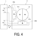
- FIG. 4 is a schematic diagram illustrating a relationship between the magnetic poles of the rotor 21 and the magnetic poles of the coils 22a and 22b when a fluctuation in phase of a drive current occurs in the stepping motor 2.
- FIG. 4 shows an example of the coil 22a having the S pole and being adjacent to the S pole 21s of the rotor 21.
- the current control unit 12 of the motor control device 1 normally controls the current, and thus the phase of the current energizing each of the A-phase coil 22a and the B-phase coil 22b is gradually switched.
- the rotor 21 of the stepping motor 2 rotates smoothly.
- the control of the current to each of the A-phase coil 22a and the B-phase coil 22b as described above is performed in either the open-loop control or the closed-loop control.
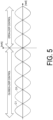
- FIG. 5 is a schematic diagram illustrating a relationship between a command value of a rotational position of a rotor and an actual rotational position when the closed-loop control is switched to the open-loop control by a motor control device of a reference example.
- a waveform C1 indicated by a solid line indicates a phase of a drive current subjected to the closed-loop control by the motor control device of the reference example.
- a waveform O1 indicated by a broken line indicates a phase of the drive current subjected to the open-loop control by the motor control device of the reference example.
- the phase of the drive current subjected to the open-loop control is not subjected to the feedback control in accordance with the rotational position of the rotor 21. For this reason, in FIG. 5 , the phase of the drive current subjected to the open-loop control indicated by the waveform O1 is shifted from the phase of the drive current subjected to the closed-loop control indicated by the waveform C1 by, for example, ⁇ (180°).
- the magnetic poles of the coils 22a and 22b controlled by the closed-loop control rapidly change to the magnetic poles of the coils 22a and 22b controlled by the open-loop control.
- the magnetic poles of the coils 22a and 22b rapidly change and, for example, as illustrated in FIG.
- the magnetic poles of the rotor 21 and the magnetic poles of the coils 22a and 22b have the same polarity, the magnetic poles (the S pole 21s and the N pole 21n) of the rotor 21 rapidly repel the magnetic poles of the coils 22a and 22b.
- vibration is considered to be generated from the rotor 21.
- the magnetic poles (the S pole 21s and the N pole 21n) of the rotor 21 are considered not to follow the change in the magnetic poles of the coils 22a and 22b, and thus a step-out occurs.
- the rotational position correction unit 13 specifies a difference (first phase difference) between an actual rotational position of the rotor 21 in the open-loop control and a target rotational position of the rotor 21. Based on the acquired first phase difference, the rotational position correction unit 13 corrects a difference (second phase difference) between a rotational position in the closed-loop control and a rotational position in the open-loop control when the current control unit 12 switches from the closed-loop control to the open-loop control.
- the first phase difference specified by the rotational position correction unit 13 is stored in a phase difference storage unit 31 provided at the storage unit 30.
- FIG. 6 is a schematic diagram illustrating a relationship between a command value of a rotational position of the rotor 21 and an actual rotational position when the closed-loop control is switched to the open-loop control by the motor control device 1.
- a waveform C2 indicated by a solid line indicates a phase of a drive current controlled by the closed-loop control in the motor control device 1.
- a waveform O2 indicated by a broken line indicates a phase of the drive current in the open-loop control before corrected by the rotational position correction unit 13 in the motor control device 1.
- the phase of the waveform O2 is shifted from the phase of the drive current in the closed-loop control indicated by the waveform C2 by, for example, ⁇ (180°).
- the rotational position correction unit 13 specifies, as the second phase difference, a difference between the phase of the current in the closed-loop control indicated by the waveform C2 in FIG. 6 and the phase of the current in the open-loop control indicated by the waveform O2 in FIG. 6 .
- the rotational position correction unit 13 corrects the specified second phase difference based on the previously acquired first phase difference.
- a phase difference between the phase of the drive current by the open-loop control after the correction indicated by a waveform O3 and the phase of the drive current in the closed-loop control indicated by the waveform C2 is eliminated.
- the first phase difference and the second phase difference can be specified from, for example, the phase (electrical angle) of the drive current of the stepping motor 2.
- the first phase difference can be specified by, for example, a phase difference between a phase of the drive current by the current command value generated by the open-loop control circuit 121 based on the drive command from the outside such as a host device and a phase of the drive current by the current command value generated by the closed-loop control circuit 122.
- the first phase difference may be specified by converting the rotational position of the rotor 21 into the phase of the drive current of the stepping motor 2.
- the first phase difference and the second phase difference may be specified based on the rotational position (mechanical angle) of the rotor 21 acquired from an encoder attached to the stepping motor 2, for example.
- FIG. 7 is a flowchart illustrating an example of a motor control method executed by the motor control device. An example of the motor control method by the motor control device 1 described above will be described with reference to FIG. 7 .
- the motor control device 1 In response to a drive command from the outside such as a host device, the motor control device 1 starts generation of a drive current of the stepping motor 2 (step S101).
- the motor control device 1 causes the open-loop control circuit 121 to execute control of the drive current of the stepping motor 2 in response to the drive command from the outside such as a host device (step S102).
- the control switching unit 123 determines whether a switching condition from the open-loop control to the closed-loop control has been reached (step S103).
- the switching condition from the open-loop control to the closed-loop control is, for example, whether the rotational speed of the rotor 21 acquired from the rotational position acquisition unit 11 has reached a speed exceeding a predetermined condition.
- the control switching unit 123 determines that the rotational speed of the rotor 21 has not reached the predetermined condition (S103: NO)
- the control switching unit 123 repeats the processing of S103.
- control switching unit 123 switches the circuit for controlling the drive current of the stepping motor 2 from the open-loop control circuit 121 to the closed-loop control circuit 122, and executes control processing of the drive current (step S 104).
- the rotational position correction unit 13 specifies a difference (first phase difference) between the rotational position of the rotor 21 in the open-loop control and the rotational position of the rotor 21 in the closed-loop control when the open-loop control is switched to the closed-loop control (step S105).
- the control switching unit 123 determines whether a switching condition from the closed-loop control to the open-loop control has been reached (step S106).
- the switching condition from the closed-loop control to the open-loop control is, for example, whether the rotational speed of the rotor 21 acquired from the rotational position acquisition unit 11 has reached a speed below a predetermined condition.
- the control switching unit 123 determines that the rotational speed of the rotor 21 has not reached the predetermined condition (S 106: NO)
- the control switching unit 123 repeats the processing of S106.
- control switching unit 123 switches the circuit for controlling the drive current of the stepping motor 2 from the closed-loop control circuit 122 to the open-loop control circuit 121, and executes control processing of the drive current (step S 107).
- the rotational position correction unit 13 corrects, based on the first phase difference, a difference (second phase difference) between the rotational position of the rotor 21 in the closed-loop control and the rotational position of the rotor 21 in the open-loop control when the closed-loop control is switched to the open-loop control (step S108).
- the motor control device 1 determines whether there is an operation end command such as an end of the drive command from the outside such as a host device (step S 109), and ends the processing when there is an operation end command (S109: YES). On the other hand, when there is no operation end command (S109: NO), the motor control device 1 repeats the processing of correcting the second phase difference based on the first phase difference indicated in S 108.
- an operation end command such as an end of the drive command from the outside such as a host device
- the motor control device 1 configured as described above includes the current control unit 12 controlling the current by either the open-loop control or the closed-loop control.
- the motor control device 1 also includes the rotational position correction unit 13 correcting a difference between a rotational position in the closed-loop control and a rotational position in the open-loop control when the current control unit switches from the closed-loop control to the open-loop control.
- the motor control device 1 can suppress a change between the magnetic poles of the coils 22a and 22b controlled by the closed-loop control and the magnetic poles of the coils 22a and 22b controlled by the open-loop control, even when there is a difference between the phase of the drive current controlled by the open-loop control and the phase of the drive current controlled by the closed-loop control. For this reason, the motor control device 1 can suppress occurrence of vibration from the rotor 21 of the stepping motor 2. In addition, the motor control device 1 can suppress occurrence of a step-out because the magnetic poles of the rotor 21 of the stepping motor 2 cannot follow the change in the magnetic poles of the coils 22a and 22b.
- the motor control device 1 including the rotational position correction unit 13 it is possible to suppress the fluctuation in phase of the drive current when trying to switch between the feedback control and the open-loop control.
Landscapes
- Engineering & Computer Science (AREA)
- Power Engineering (AREA)
- Control Of Stepping Motors (AREA)
Abstract
Description
- The present invention relates to a motor control device and a motor control method.
- In a stepping motor, in order to implement a stable operation at the time of high-speed rotation, drive may be controlled by a closed-loop control. On the other hand, in the case where the drive of the stepping motor is controlled by the closed-loop control, a vibration motion called hunting may occur when stopping the rotation. Therefore, as a method of controlling the drive of the stepping motor, it is conceivable to switch from the closed-loop control to an open-loop control when stopping the rotation.
- Note that, as a technique for controlling drive of a motor, there is known a technique for reducing a difference in rotational speed of a motor at the time of switching between an open-loop control and a feedback control (see Patent Document 1).
- Patent Document 1:
JP 2018-191461 A - However, in the stepping motor, when the drive control method is switched from the closed-loop control to the open-loop control, fluctuations in phase of drive current may occur. In the stepping motor, the fluctuations in phase of the drive current may cause vibrations. Therefore, when trying to switch between the feedback control and the open-loop control in the stepping motor, it is necessary to suppress the fluctuations in phase of the drive current.
- The present invention is for the problem described above, as an example, and has an object to provide a motor control device capable of suppressing a fluctuation in phase of a drive current when trying to switch between a feedback control and an open-loop control.
- In order to achieve the object described above, a motor control device according to the present invention includes: a current control unit configured to control a current by either an open-loop control of controlling a current to be supplied to a motor based on a current command value or a closed-loop control of controlling the current to be supplied to the motor based on the current command value and a rotational position of a rotor of the motor; and a rotational position correction unit configured to correct a second phase difference based on a first phase difference, the first phase difference being a difference between a rotational position of the rotor in a state where the current control unit controls the current by the closed-loop control and a target rotational position of the rotor, and the second phase difference being a difference between a rotational position in the closed-loop control and a rotational position in the open-loop control when the current control unit switches from the closed-loop control to the open-loop control.
- According to the motor control device of the present invention, it is possible to suppress a fluctuation in phase of a drive current when trying to switch between the feedback control and the open-loop control.
-
-
FIG. 1 is a functional block diagram schematically illustrating a configuration of a motor control device according to an embodiment of the present invention. -
FIG. 2 is a diagram schematically illustrating a circuit configuration of a stepping motor. -
FIG. 3 is a schematic view illustrating a relationship between magnetic poles of a normal rotor and magnetic poles of coils in the stepping motor illustrated inFIG. 2 . -
FIG. 4 is a schematic diagram illustrating a relationship between the magnetic poles of the rotor and the magnetic poles of the coils when a fluctuation in phase of a drive current occurs in the stepping motor illustrated inFIG. 2 . -
FIG. 5 is a schematic diagram illustrating a relationship between a command value of a rotational position of a rotor and an actual rotational position when a closed-loop control is switched to an open-loop control by a motor control device of a reference example. -
FIG. 6 is a schematic diagram illustrating a relationship between a command value of a rotational position of a rotor and an actual rotational position when a closed-loop control is switched to an open-loop control by the motor control device illustrated inFIG. 1 . -
FIG. 7 is a flowchart illustrating an example of a motor control method executed by the motor control device illustrated inFIG. 1 . - A motor control device and a motor control method according to an embodiment of the present invention will be described below with reference to the drawings.
-
FIG. 1 is a functional block diagram schematically illustrating a configuration of amotor control device 1 according to an embodiment of the present invention. - As illustrated in
FIG. 1 , themotor control device 1 of the present embodiment includes acontrol unit 10 and astorage unit 30. Thecontrol unit 10 includes acurrent control unit 12 and a rotationalposition correction unit 13. Hereinafter, configurations and operations of themotor control device 1 will be specifically described. - The
motor control device 1 is a device controlling an operation of a steppingmotor 2 by controlling A-phase and B-phase currents supplied to the steppingmotor 2. -
FIG. 2 is a diagram schematically illustrating a circuit configuration of thestepping motor 2. - As illustrated in
FIG. 2 , thestepping motor 2 includes twocoils rotor 21, and a plurality of stator yokes (not illustrated). - Each of the
coils coils control unit 10. Thecoil 22a is an A-phase coil. Thecoil 22b is a B-phase coil. Coil currents (A/B phase currents) with different phases flow through therespective coils - The
rotor 21 includes a permanent magnet subjected to multipolar magnetization along a circumferential direction, and thus anS pole 21s and anN pole 21n are alternately inverted. Note that inFIG. 2 , therotor 21 is illustrated in a simplified manner, and thus oneS pole 21s and oneN pole 21n are provided. The stator yoke is disposed around therotor 21 in proximity to an outer circumferential part of therotor 21. The phases of the A/B phase currents flowing through each of thecoils rotor 21 rotates. - As illustrated in
FIG. 1 , the rotationalposition acquisition unit 11 is connected to the steppingmotor 2 and themotor control device 1. The rotationalposition acquisition unit 11 acquires a rotational position of the rotor 21 (seeFIG. 2 ) of thestepping motor 2. Specifically, the rotationalposition acquisition unit 11 is, for example, an encoder. - The encoder is attached to an output shaft of the
stepping motor 2. The encoder may be, for example, an incremental-type rotary encoder outputting two A-phase and B-phase pulse signals to a rotationalposition calculation unit 14 and a rotationalspeed calculation unit 15 of themotor control device 1 described below in response to rotation of the output shaft of thestepping motor 2. Note that the output phase of the encoder is not limited to two phases and may be, for example, one phase or three phases. In addition, the encoder is not limited to the incremental-type rotary encoder. The encoder may also be, for example, an absolute-type rotary encoder specifying rotation angles over a plurality of rotations of the output shaft of thestepping motor 2 and outputting the rotation angles to the rotationalposition calculation unit 14 and the rotationalspeed calculation unit 15. - As illustrated in
FIG. 1 , thecurrent control unit 12, the rotationalposition correction unit 13, the rotationalposition calculation unit 14, and the rotationalspeed calculation unit 15 are implemented by a computer as an example of a program processing device including thecontrol unit 10 as an example of a processor such as a CPU and thestorage unit 30 to be implemented by various storage devices such as a RAM and a ROM. The computer is an example of a program processing device having a configuration. In the configuration, thecontrol unit 10, thestorage unit 30, and peripheral circuits such as a counter (timer), an A/D conversion circuit, a D/A conversion circuit, a clock generation circuit, and an input/output I/F circuit not illustrated are connected to one another via a bus or a dedicated line. By causing thecontrol unit 10 to execute a computer program in order to execute a motor control method stored in thestorage unit 30, thecontrol unit 10 functions as thecurrent control unit 12, the rotationalposition correction unit 13, the rotationalposition calculation unit 14, and therotation calculation unit 15. - The rotational
position calculation unit 14 calculates a rotational position of therotor 21 of thestepping motor 2 based on the A-phase and B-phase pulse signals output by the encoder. The rotationalposition calculation unit 14 outputs the calculated rotational position to a closed-loop control circuit 122. The rotationalspeed calculation unit 15 calculates a rotational speed of therotor 21 of thestepping motor 2 based on the A-phase and B-phase pulse signals output by the encoder. The rotationalspeed calculation unit 15 outputs the calculated rotational speed to the closed-loop control circuit 122 and acontrol switching unit 123. - The
current control unit 12 controls a current by either an open-loop control of controlling a current to be supplied to the steppingmotor 2 based on a current command value or a closed-loop control of controlling the current to be supplied to the steppingmotor 2 based on the current command value and a rotational position. Thecurrent control unit 12 includes acurrent detection unit 120, an open-loop control circuit 121, a closed-loop control circuit 122, acontrol switching unit 123, and a motordrive control circuit 124, as functional units controlling the current to be supplied to thestepping motor 2. - The
current detection unit 120 detects the A/B phase currents output from the motordrive control circuit 124 and outputs the A/B phase currents to the closed-loop control circuit 122 and the rotationalposition correction unit 13. Specifically, thecurrent detection unit 120 receives a sensing result of a coil current output from a current sensor (not illustrated). The coil current is a current flowing through the coil of each phase of the steppingmotor 2. The current sensor senses the coil current. The current sensor outputs a sensing result of the coil current to thecurrent detection unit 120. The current sensor is, for example, a shunt resistor. - The
current detection unit 120 measures the A/B phase currents based on the input sensing result. Thecurrent detection unit 120 outputs measured values of the A/B phase currents to the closed-loop control circuit 122 and the rotationalposition correction unit 13. Thecurrent detection unit 120 includes, for example, an A/D conversion circuit. - The open-
loop control circuit 121 generates a current command value of the steppingmotor 2 in response to a drive command of the steppingmotor 2 input from the outside such as a host device using the steppingmotor 2. The drive command indicates, for example, a command position in the operation of the steppingmotor 2. The current command value generated by the open-loop control circuit 121 is output to the motordrive control circuit 124. Note that, although the drive command is described as being input from the outside in the present embodiment, the drive command may be generated inside thecontrol unit 10. - The closed-
loop control circuit 122 generates a current command value by a feedback control. Specifically, the closed-loop control circuit 122 generates the current command value based on the drive command, the rotational position of therotor 21 calculated by the rotationalposition calculation unit 14, the rotational speed calculated by the rotationalspeed calculation unit 15, and the A/B phase currents supplied to the steppingmotor 2 acquired from thecurrent detection unit 120. The closed-loop control circuit 122 obtains a difference between the command position indicated by the drive command and the rotational position of therotor 21. The closed-loop control circuit 122 determines a target speed of therotor 21 based on the obtained difference in position. The closed-loop control circuit 122 obtains a difference between the target speed and the rotational speed of therotor 21. The closed-loop control circuit 122 determines a target current value based on the obtained difference in speed. The closed-loop control circuit 122 obtains a difference between the target current value and the A/B phase current. The closed-loop control circuit 122 generates a current command value based on the obtained difference in current. The current command value generated by the closed-loop control circuit 122 is output to the motordrive control circuit 124. - The
control switching unit 123 switches the control of current of the steppingmotor 2 to either the open-loop control circuit 121 or the closed-loop control circuit 122 in accordance with the rotational speed of therotor 21 calculated by the rotationalspeed calculation unit 15. Thecontrol switching unit 123 switches between the open-loop control circuit 121 and the closed-loop control circuit 122 based on whether the rotational speed of therotor 21 has reached a predetermined condition, for example, a threshold value. By thecontrol switching unit 123 operating in this way, themotor control device 1 can suppress occurrence of hunting when therotor 21 of the steppingmotor 2 is in a stopped state. - The motor
drive control circuit 124 converts the current command value generated by the open-loop control circuit 121 or the closed-loop control circuit 122 into a current signal of a two-phase (A-phase and B-phase) fixed coordinate system and outputs the current signal to the steppingmotor 2. -
FIG. 3 is a schematic diagram illustrating a relationship between magnetic poles of thenormal rotor 21 and magnetic poles of the coils 22 and 23 in the steppingmotor 2.FIG. 4 is a schematic diagram illustrating a relationship between the magnetic poles of therotor 21 and the magnetic poles of thecoils motor 2.FIG. 4 shows an example of thecoil 22a having the S pole and being adjacent to theS pole 21s of therotor 21. With reference toFIGS. 3 and4 , a description will be given of a difference between the rotational position in the closed-loop control and the rotational position in the open-loop control of performing correction by the rotationalposition correction unit 13. - As illustrated in
FIG. 3 , in the steppingmotor 2, thecurrent control unit 12 of themotor control device 1 normally controls the current, and thus the phase of the current energizing each of theA-phase coil 22a and the B-phase coil 22b is gradually switched. By controlling the current energizing each of theA-phase coil 22a and the B-phase coil 22b as described above, therotor 21 of the steppingmotor 2 rotates smoothly. The control of the current to each of theA-phase coil 22a and the B-phase coil 22b as described above is performed in either the open-loop control or the closed-loop control. -
FIG. 5 is a schematic diagram illustrating a relationship between a command value of a rotational position of a rotor and an actual rotational position when the closed-loop control is switched to the open-loop control by a motor control device of a reference example. InFIG. 5 , a waveform C1 indicated by a solid line indicates a phase of a drive current subjected to the closed-loop control by the motor control device of the reference example. In addition, inFIG. 5 , a waveform O1 indicated by a broken line indicates a phase of the drive current subjected to the open-loop control by the motor control device of the reference example. In the motor control device of the reference example, the phase of the drive current subjected to the open-loop control is not subjected to the feedback control in accordance with the rotational position of therotor 21. For this reason, inFIG. 5 , the phase of the drive current subjected to the open-loop control indicated by the waveform O1 is shifted from the phase of the drive current subjected to the closed-loop control indicated by the waveform C1 by, for example, π (180°). - As described above, when there is a difference between the phase of the drive current subjected to the open-loop control and the phase of the drive current subjected to the closed-loop control, in the stepping
motor 2, the magnetic poles of thecoils coils coils FIG. 4 , the magnetic poles of therotor 21 and the magnetic poles of thecoils S pole 21s and theN pole 21n) of therotor 21 rapidly repel the magnetic poles of thecoils motor 2, vibration is considered to be generated from therotor 21. In addition, in the above-described case, in the steppingmotor 2, the magnetic poles (theS pole 21s and theN pole 21n) of therotor 21 are considered not to follow the change in the magnetic poles of thecoils - In order to suppress the above-described fluctuation in phase of the drive current in the stepping
motor 2, the rotationalposition correction unit 13 specifies a difference (first phase difference) between an actual rotational position of therotor 21 in the open-loop control and a target rotational position of therotor 21. Based on the acquired first phase difference, the rotationalposition correction unit 13 corrects a difference (second phase difference) between a rotational position in the closed-loop control and a rotational position in the open-loop control when thecurrent control unit 12 switches from the closed-loop control to the open-loop control. The first phase difference specified by the rotationalposition correction unit 13 is stored in a phasedifference storage unit 31 provided at thestorage unit 30. -
FIG. 6 is a schematic diagram illustrating a relationship between a command value of a rotational position of therotor 21 and an actual rotational position when the closed-loop control is switched to the open-loop control by themotor control device 1. InFIG. 6 , a waveform C2 indicated by a solid line indicates a phase of a drive current controlled by the closed-loop control in themotor control device 1. In addition, inFIG. 6 , a waveform O2 indicated by a broken line indicates a phase of the drive current in the open-loop control before corrected by the rotationalposition correction unit 13 in themotor control device 1. Similarly to the waveform O1 illustrated inFIG. 5 , the phase of the waveform O2 is shifted from the phase of the drive current in the closed-loop control indicated by the waveform C2 by, for example, π (180°). - When the
current control unit 12 switches from the closed-loop control to the closed-loop control, the rotationalposition correction unit 13 specifies, as the second phase difference, a difference between the phase of the current in the closed-loop control indicated by the waveform C2 inFIG. 6 and the phase of the current in the open-loop control indicated by the waveform O2 inFIG. 6 . - The rotational
position correction unit 13 corrects the specified second phase difference based on the previously acquired first phase difference. InFIG. 6 , a phase difference between the phase of the drive current by the open-loop control after the correction indicated by a waveform O3 and the phase of the drive current in the closed-loop control indicated by the waveform C2 is eliminated. - The first phase difference and the second phase difference can be specified from, for example, the phase (electrical angle) of the drive current of the stepping
motor 2. Specifically, the first phase difference can be specified by, for example, a phase difference between a phase of the drive current by the current command value generated by the open-loop control circuit 121 based on the drive command from the outside such as a host device and a phase of the drive current by the current command value generated by the closed-loop control circuit 122. Note that the first phase difference may be specified by converting the rotational position of therotor 21 into the phase of the drive current of the steppingmotor 2. In addition, the first phase difference and the second phase difference may be specified based on the rotational position (mechanical angle) of therotor 21 acquired from an encoder attached to the steppingmotor 2, for example. -
FIG. 7 is a flowchart illustrating an example of a motor control method executed by the motor control device. An example of the motor control method by themotor control device 1 described above will be described with reference toFIG. 7 . - In response to a drive command from the outside such as a host device, the
motor control device 1 starts generation of a drive current of the stepping motor 2 (step S101). - The
motor control device 1 causes the open-loop control circuit 121 to execute control of the drive current of the steppingmotor 2 in response to the drive command from the outside such as a host device (step S102). - In the
motor control device 1, thecontrol switching unit 123 determines whether a switching condition from the open-loop control to the closed-loop control has been reached (step S103). The switching condition from the open-loop control to the closed-loop control is, for example, whether the rotational speed of therotor 21 acquired from the rotationalposition acquisition unit 11 has reached a speed exceeding a predetermined condition. When thecontrol switching unit 123 determines that the rotational speed of therotor 21 has not reached the predetermined condition (S103: NO), thecontrol switching unit 123 repeats the processing of S103. - When the rotational speed of the
rotor 21 has reached the predetermined condition (S 102: YES), thecontrol switching unit 123 switches the circuit for controlling the drive current of the steppingmotor 2 from the open-loop control circuit 121 to the closed-loop control circuit 122, and executes control processing of the drive current (step S 104). - The rotational
position correction unit 13 specifies a difference (first phase difference) between the rotational position of therotor 21 in the open-loop control and the rotational position of therotor 21 in the closed-loop control when the open-loop control is switched to the closed-loop control (step S105). - In the
motor control device 1, thecontrol switching unit 123 determines whether a switching condition from the closed-loop control to the open-loop control has been reached (step S106). The switching condition from the closed-loop control to the open-loop control is, for example, whether the rotational speed of therotor 21 acquired from the rotationalposition acquisition unit 11 has reached a speed below a predetermined condition. When thecontrol switching unit 123 determines that the rotational speed of therotor 21 has not reached the predetermined condition (S 106: NO), thecontrol switching unit 123 repeats the processing of S106. - When the rotational speed of the
rotor 21 has reached a speed below the predetermined condition (S106: YES), thecontrol switching unit 123 switches the circuit for controlling the drive current of the steppingmotor 2 from the closed-loop control circuit 122 to the open-loop control circuit 121, and executes control processing of the drive current (step S 107). - The rotational
position correction unit 13 corrects, based on the first phase difference, a difference (second phase difference) between the rotational position of therotor 21 in the closed-loop control and the rotational position of therotor 21 in the open-loop control when the closed-loop control is switched to the open-loop control (step S108). - The
motor control device 1 determines whether there is an operation end command such as an end of the drive command from the outside such as a host device (step S 109), and ends the processing when there is an operation end command (S109: YES). On the other hand, when there is no operation end command (S109: NO), themotor control device 1 repeats the processing of correcting the second phase difference based on the first phase difference indicated inS 108. - The
motor control device 1 configured as described above includes thecurrent control unit 12 controlling the current by either the open-loop control or the closed-loop control. Themotor control device 1 also includes the rotationalposition correction unit 13 correcting a difference between a rotational position in the closed-loop control and a rotational position in the open-loop control when the current control unit switches from the closed-loop control to the open-loop control. By including the rotationalposition correction unit 13, themotor control device 1 can suppress a change between the magnetic poles of thecoils coils motor control device 1 can suppress occurrence of vibration from therotor 21 of the steppingmotor 2. In addition, themotor control device 1 can suppress occurrence of a step-out because the magnetic poles of therotor 21 of the steppingmotor 2 cannot follow the change in the magnetic poles of thecoils - Therefore, according to the
motor control device 1 including the rotationalposition correction unit 13, it is possible to suppress the fluctuation in phase of the drive current when trying to switch between the feedback control and the open-loop control. - In addition, a person skilled in the art can appropriately modify the present invention according to conventionally known knowledge. Such modifications are of course included in the scope of the present invention as long as these modifications still include the configuration of the disclosure.
- 1: Motor control device, 2: Stepping motor, 10: Control unit, 11: Rotational position acquisition unit, 12: Current control unit, 13: Rotational Position correction unit, 14: Rotational position calculation unit, 15: Rotational speed calculation unit, 21: Rotor, 21s: S pole, 21n: N pole, 22a, 22b: Coil, 30: Storage unit, 31: Phase difference storage unit, 121: Open-loop control circuit, 122: Closed-loop control circuit, 123: Control switching unit, 124: Motor drive control circuit
Claims (6)
- A motor control device comprising:a current control unit configured to control a current by either an open-loop control of controlling a current to be supplied to a motor based on a current command value or a closed-loop control of controlling the current to be supplied to the motor based on the current command value and a rotational position of a rotor of the motor; anda rotational position correction unit configured to correct a second phase difference based on a first phase difference, the first phase difference being a difference between a rotational position of the rotor in a state where the current control unit controls the current by the closed-loop control and a target rotational position of the rotor, the second phase difference being a difference between a rotational position in the closed-loop control and a rotational position in the open-loop control when the current control unit switches from the closed-loop control to the open-loop control.
- The motor control device according to claim 1, comprising:
a phase difference storage unit configured to store the first phase difference. - The motor control device according to claim 1 or 2, wherein
the rotational position correction unit specifies the first phase difference based on a difference between a phase of the current in the state where the current control unit controls the current by the closed-loop control and a phase of the current in a state where the current control unit controls the current by the open-loop control. - The motor control device according to any one of claims 1 to 3, wherein
the rotational position correction unit specifies, as the second phase difference, a difference between a phase of the current in the closed-loop control and a phase of the current in the open-loop control when the current control unit switches from the closed-loop control to the open-loop control. - The motor control device according to any one of claims 1 to 4, wherein
the rotational position correction unit specifies the first phase difference based on a difference between a phase of the current in the state where the current control unit controls the current by the closed-loop control and a phase of the current by the current command value. - A motor control method for causing a computer to execute:acquiring a rotational position of a rotor of a motor;controlling a current by either an open-loop control of controlling a current to be supplied to the motor based on a current command value or a closed-loop control of controlling the current to be supplied to the motor based on the current command value and a rotational position; andcorrecting a second phase difference based on a first phase difference, the first phase difference being a difference between a rotational position of the rotor in a state where the current is controlled by the closed-loop control and a rotational position of the rotor in a state where the current is controlled by the open-control loop, the second phase difference being a difference between a rotational position in the closed-loop control and a rotational position in the open-loop control when switching from the closed-loop control to the open-loop control.
Applications Claiming Priority (2)
| Application Number | Priority Date | Filing Date | Title |
|---|---|---|---|
| JP2021188922A JP7814727B2 (en) | 2021-11-19 | 2021-11-19 | Stepping motor control device and stepping motor control method |
| PCT/JP2022/041026 WO2023090159A1 (en) | 2021-11-19 | 2022-11-02 | Motor control device and motor control method |
Publications (2)
| Publication Number | Publication Date |
|---|---|
| EP4436030A1 true EP4436030A1 (en) | 2024-09-25 |
| EP4436030A4 EP4436030A4 (en) | 2025-10-29 |
Family
ID=86396846
Family Applications (1)
| Application Number | Title | Priority Date | Filing Date |
|---|---|---|---|
| EP22895441.8A Pending EP4436030A4 (en) | 2021-11-19 | 2022-11-02 | ENGINE CONTROL DEVICE AND ENGINE CONTROL METHOD |
Country Status (5)
| Country | Link |
|---|---|
| US (1) | US20250007432A1 (en) |
| EP (1) | EP4436030A4 (en) |
| JP (1) | JP7814727B2 (en) |
| CN (1) | CN118382991A (en) |
| WO (1) | WO2023090159A1 (en) |
Family Cites Families (7)
| Publication number | Priority date | Publication date | Assignee | Title |
|---|---|---|---|---|
| US20070040529A1 (en) * | 2005-08-19 | 2007-02-22 | Smc Corporation Of America | Stepping motor control system and method for controlling a stepping motor using closed and open loop controls |
| WO2008026270A1 (en) * | 2006-08-31 | 2008-03-06 | Mitsubishi Electric Corporation | Electric motor driving device, and compressor driving device |
| JP5510628B2 (en) * | 2008-12-27 | 2014-06-04 | ダイヤモンド電機株式会社 | Inverter control circuit for synchronous motor and synchronous motor control apparatus provided with the same |
| JP6921616B2 (en) | 2017-05-10 | 2021-08-18 | キヤノン株式会社 | Controls, optics, control methods, and programs |
| JP6980555B2 (en) * | 2018-02-16 | 2021-12-15 | キヤノン株式会社 | Motor control device, sheet transfer device and image forming device |
| JP2019208329A (en) * | 2018-05-30 | 2019-12-05 | ダイヤモンド電機株式会社 | Sensorless vector control device and sensorless vector control method |
| JP2020036515A (en) * | 2018-08-31 | 2020-03-05 | キヤノン株式会社 | Motor driving device, motor driving method, and program |
-
2021
- 2021-11-19 JP JP2021188922A patent/JP7814727B2/en active Active
-
2022
- 2022-11-02 CN CN202280075106.0A patent/CN118382991A/en active Pending
- 2022-11-02 US US18/709,677 patent/US20250007432A1/en active Pending
- 2022-11-02 EP EP22895441.8A patent/EP4436030A4/en active Pending
- 2022-11-02 WO PCT/JP2022/041026 patent/WO2023090159A1/en not_active Ceased
Also Published As
| Publication number | Publication date |
|---|---|
| EP4436030A4 (en) | 2025-10-29 |
| JP2023075796A (en) | 2023-05-31 |
| WO2023090159A1 (en) | 2023-05-25 |
| JP7814727B2 (en) | 2026-02-17 |
| CN118382991A (en) | 2024-07-23 |
| US20250007432A1 (en) | 2025-01-02 |
Similar Documents
| Publication | Publication Date | Title |
|---|---|---|
| EP2689527B1 (en) | A method and apparatus for control of electrical machines | |
| US8508176B2 (en) | Drive apparatus for stepping motor | |
| EP2998708A1 (en) | Rotation angle detection system, rotation angle detection method, rotation angle detection unit, and synchronous motor control system | |
| JP2002291282A (en) | Drive device for sensorless motor | |
| EP3644495B1 (en) | Motor control device and control method of motor control device | |
| EP3683954A1 (en) | Motor drive system and motor control method | |
| JP5770701B2 (en) | Stepping motor drive control device | |
| EP1798847A2 (en) | Electronic commutation circuits | |
| JP5322501B2 (en) | Drive device and electronic device | |
| JP6723881B2 (en) | Electric motor control device and electric motor control method | |
| CN113196645B (en) | Motor system | |
| US20250007432A1 (en) | Motor control device and motor control method | |
| JP2004320847A (en) | Stepping motor control method and stepping motor control device | |
| JP5464793B2 (en) | Motor drive device | |
| JP4508970B2 (en) | Stepping motor drive device | |
| US20250192700A1 (en) | Motor control device and magnetic pole position calculation method | |
| GB2319908A (en) | Starting and direction control of two phase switched reluctance machine | |
| JP2015033191A (en) | Motor control device | |
| CN109980999B (en) | Motor control device and motor control method | |
| US10978972B2 (en) | Actuator controller, control method therefor, and storage medium storing control program therefor | |
| EP3618262B1 (en) | Motor control apparatus and motor control method | |
| EP3618261B1 (en) | Motor control apparatus and motor control method | |
| JP2016129491A (en) | Magnetic pole position correction method for motor | |
| US20250023496A1 (en) | Motor drive control device, motor unit, and motor drive control method | |
| JP5489738B2 (en) | Motor control device and optical apparatus |
Legal Events
| Date | Code | Title | Description |
|---|---|---|---|
| STAA | Information on the status of an ep patent application or granted ep patent |
Free format text: STATUS: THE INTERNATIONAL PUBLICATION HAS BEEN MADE |
|
| PUAI | Public reference made under article 153(3) epc to a published international application that has entered the european phase |
Free format text: ORIGINAL CODE: 0009012 |
|
| STAA | Information on the status of an ep patent application or granted ep patent |
Free format text: STATUS: REQUEST FOR EXAMINATION WAS MADE |
|
| 17P | Request for examination filed |
Effective date: 20240607 |
|
| AK | Designated contracting states |
Kind code of ref document: A1 Designated state(s): AL AT BE BG CH CY CZ DE DK EE ES FI FR GB GR HR HU IE IS IT LI LT LU LV MC ME MK MT NL NO PL PT RO RS SE SI SK SM TR |
|
| DAV | Request for validation of the european patent (deleted) | ||
| DAX | Request for extension of the european patent (deleted) | ||
| A4 | Supplementary search report drawn up and despatched |
Effective date: 20250925 |
|
| RIC1 | Information provided on ipc code assigned before grant |
Ipc: H02P 8/14 20060101AFI20250919BHEP Ipc: H02P 21/00 20160101ALI20250919BHEP Ipc: H02P 8/12 20060101ALI20250919BHEP Ipc: H02P 8/24 20060101ALI20250919BHEP Ipc: H02P 8/32 20060101ALI20250919BHEP |
|
| P01 | Opt-out of the competence of the unified patent court (upc) registered |
Free format text: CASE NUMBER: UPC_APP_0003839_4436030/2026 Effective date: 20260203 |