EP4435960A1 - Secondary battery having improved terminal structure - Google Patents
Secondary battery having improved terminal structure Download PDFInfo
- Publication number
- EP4435960A1 EP4435960A1 EP23883084.8A EP23883084A EP4435960A1 EP 4435960 A1 EP4435960 A1 EP 4435960A1 EP 23883084 A EP23883084 A EP 23883084A EP 4435960 A1 EP4435960 A1 EP 4435960A1
- Authority
- EP
- European Patent Office
- Prior art keywords
- terminal
- terminal structure
- secondary battery
- battery case
- negative electrode
- Prior art date
- Legal status (The legal status is an assumption and is not a legal conclusion. Google has not performed a legal analysis and makes no representation as to the accuracy of the status listed.)
- Pending
Links
Images



Classifications
-
- H—ELECTRICITY
- H01—ELECTRIC ELEMENTS
- H01M—PROCESSES OR MEANS, e.g. BATTERIES, FOR THE DIRECT CONVERSION OF CHEMICAL ENERGY INTO ELECTRICAL ENERGY
- H01M50/00—Constructional details or processes of manufacture of the non-active parts of electrochemical cells other than fuel cells, e.g. hybrid cells
- H01M50/50—Current conducting connections for cells or batteries
- H01M50/543—Terminals
- H01M50/564—Terminals characterised by their manufacturing process
- H01M50/566—Terminals characterised by their manufacturing process by welding, soldering or brazing
-
- H—ELECTRICITY
- H01—ELECTRIC ELEMENTS
- H01M—PROCESSES OR MEANS, e.g. BATTERIES, FOR THE DIRECT CONVERSION OF CHEMICAL ENERGY INTO ELECTRICAL ENERGY
- H01M50/00—Constructional details or processes of manufacture of the non-active parts of electrochemical cells other than fuel cells, e.g. hybrid cells
- H01M50/10—Primary casings; Jackets or wrappings
- H01M50/102—Primary casings; Jackets or wrappings characterised by their shape or physical structure
- H01M50/103—Primary casings; Jackets or wrappings characterised by their shape or physical structure prismatic or rectangular
-
- H—ELECTRICITY
- H01—ELECTRIC ELEMENTS
- H01M—PROCESSES OR MEANS, e.g. BATTERIES, FOR THE DIRECT CONVERSION OF CHEMICAL ENERGY INTO ELECTRICAL ENERGY
- H01M50/00—Constructional details or processes of manufacture of the non-active parts of electrochemical cells other than fuel cells, e.g. hybrid cells
- H01M50/10—Primary casings; Jackets or wrappings
- H01M50/14—Primary casings; Jackets or wrappings for protecting against damage caused by external factors
-
- H—ELECTRICITY
- H01—ELECTRIC ELEMENTS
- H01M—PROCESSES OR MEANS, e.g. BATTERIES, FOR THE DIRECT CONVERSION OF CHEMICAL ENERGY INTO ELECTRICAL ENERGY
- H01M50/00—Constructional details or processes of manufacture of the non-active parts of electrochemical cells other than fuel cells, e.g. hybrid cells
- H01M50/10—Primary casings; Jackets or wrappings
- H01M50/147—Lids or covers
- H01M50/148—Lids or covers characterised by their shape
- H01M50/15—Lids or covers characterised by their shape for prismatic or rectangular cells
-
- H—ELECTRICITY
- H01—ELECTRIC ELEMENTS
- H01M—PROCESSES OR MEANS, e.g. BATTERIES, FOR THE DIRECT CONVERSION OF CHEMICAL ENERGY INTO ELECTRICAL ENERGY
- H01M50/00—Constructional details or processes of manufacture of the non-active parts of electrochemical cells other than fuel cells, e.g. hybrid cells
- H01M50/50—Current conducting connections for cells or batteries
- H01M50/543—Terminals
- H01M50/547—Terminals characterised by the disposition of the terminals on the cells
-
- H—ELECTRICITY
- H01—ELECTRIC ELEMENTS
- H01M—PROCESSES OR MEANS, e.g. BATTERIES, FOR THE DIRECT CONVERSION OF CHEMICAL ENERGY INTO ELECTRICAL ENERGY
- H01M50/00—Constructional details or processes of manufacture of the non-active parts of electrochemical cells other than fuel cells, e.g. hybrid cells
- H01M50/50—Current conducting connections for cells or batteries
- H01M50/543—Terminals
- H01M50/547—Terminals characterised by the disposition of the terminals on the cells
- H01M50/55—Terminals characterised by the disposition of the terminals on the cells on the same side of the cell
-
- H—ELECTRICITY
- H01—ELECTRIC ELEMENTS
- H01M—PROCESSES OR MEANS, e.g. BATTERIES, FOR THE DIRECT CONVERSION OF CHEMICAL ENERGY INTO ELECTRICAL ENERGY
- H01M50/00—Constructional details or processes of manufacture of the non-active parts of electrochemical cells other than fuel cells, e.g. hybrid cells
- H01M50/50—Current conducting connections for cells or batteries
- H01M50/543—Terminals
- H01M50/552—Terminals characterised by their shape
- H01M50/553—Terminals adapted for prismatic, pouch or rectangular cells
-
- H—ELECTRICITY
- H01—ELECTRIC ELEMENTS
- H01M—PROCESSES OR MEANS, e.g. BATTERIES, FOR THE DIRECT CONVERSION OF CHEMICAL ENERGY INTO ELECTRICAL ENERGY
- H01M50/00—Constructional details or processes of manufacture of the non-active parts of electrochemical cells other than fuel cells, e.g. hybrid cells
- H01M50/50—Current conducting connections for cells or batteries
- H01M50/543—Terminals
- H01M50/552—Terminals characterised by their shape
- H01M50/553—Terminals adapted for prismatic, pouch or rectangular cells
- H01M50/557—Plate-shaped terminals
-
- H—ELECTRICITY
- H01—ELECTRIC ELEMENTS
- H01M—PROCESSES OR MEANS, e.g. BATTERIES, FOR THE DIRECT CONVERSION OF CHEMICAL ENERGY INTO ELECTRICAL ENERGY
- H01M50/00—Constructional details or processes of manufacture of the non-active parts of electrochemical cells other than fuel cells, e.g. hybrid cells
- H01M50/50—Current conducting connections for cells or batteries
- H01M50/543—Terminals
- H01M50/564—Terminals characterised by their manufacturing process
- H01M50/567—Terminals characterised by their manufacturing process by fixing means, e.g. screws, rivets or bolts
-
- H—ELECTRICITY
- H01—ELECTRIC ELEMENTS
- H01M—PROCESSES OR MEANS, e.g. BATTERIES, FOR THE DIRECT CONVERSION OF CHEMICAL ENERGY INTO ELECTRICAL ENERGY
- H01M50/00—Constructional details or processes of manufacture of the non-active parts of electrochemical cells other than fuel cells, e.g. hybrid cells
- H01M50/50—Current conducting connections for cells or batteries
- H01M50/572—Means for preventing undesired use or discharge
- H01M50/584—Means for preventing undesired use or discharge for preventing incorrect connections inside or outside the batteries
- H01M50/588—Means for preventing undesired use or discharge for preventing incorrect connections inside or outside the batteries outside the batteries, e.g. incorrect connections of terminals or busbars
-
- H—ELECTRICITY
- H01—ELECTRIC ELEMENTS
- H01M—PROCESSES OR MEANS, e.g. BATTERIES, FOR THE DIRECT CONVERSION OF CHEMICAL ENERGY INTO ELECTRICAL ENERGY
- H01M2220/00—Batteries for particular applications
- H01M2220/10—Batteries in stationary systems, e.g. emergency power source in plant
-
- H—ELECTRICITY
- H01—ELECTRIC ELEMENTS
- H01M—PROCESSES OR MEANS, e.g. BATTERIES, FOR THE DIRECT CONVERSION OF CHEMICAL ENERGY INTO ELECTRICAL ENERGY
- H01M2220/00—Batteries for particular applications
- H01M2220/20—Batteries in motive systems, e.g. vehicle, ship, plane
-
- Y—GENERAL TAGGING OF NEW TECHNOLOGICAL DEVELOPMENTS; GENERAL TAGGING OF CROSS-SECTIONAL TECHNOLOGIES SPANNING OVER SEVERAL SECTIONS OF THE IPC; TECHNICAL SUBJECTS COVERED BY FORMER USPC CROSS-REFERENCE ART COLLECTIONS [XRACs] AND DIGESTS
- Y02—TECHNOLOGIES OR APPLICATIONS FOR MITIGATION OR ADAPTATION AGAINST CLIMATE CHANGE
- Y02E—REDUCTION OF GREENHOUSE GAS [GHG] EMISSIONS, RELATED TO ENERGY GENERATION, TRANSMISSION OR DISTRIBUTION
- Y02E60/00—Enabling technologies; Technologies with a potential or indirect contribution to GHG emissions mitigation
- Y02E60/10—Energy storage using batteries
Definitions
- the present invention relates to a secondary battery, and more particularly to a prismatic secondary battery having an improved terminal structure in which the arrangement structure of the positive and/or negative electrode terminals can be easily and reliably varied.
- secondary batteries can be recharged and have been researched and developed in recent years due to their potential for miniaturization and large capacity.
- the demand for the secondary battery as an energy source is increasing rapidly due to the technological development and increasing demand for mobile devices, electric vehicles, and energy storage systems, which are emerging in response to the need for environmental protection.
- Secondary batteries are categorized into coin batteries, cylindrical batteries, prismatic batteries, and pouch batteries based on the shape of the battery case.
- the electrode assembly mounted inside the battery case is a charging and discharging power generation element consisting of a stacked structure of electrodes and separators.
- Electrode assemblies can be broadly categorized into (1) Jellyroll type, which is wound with a separator between the positive and negative electrodes of an active material-coated sheet, (2) Stack type, in which a plurality of positive and negative electrodes is sequentially stacked with an interposed separator, and (3) Stack & Folding type, in which stacked unit cells are wound with a long length of separator film.
- prismatic secondary batteries are mostly composed of positive and negative electrode terminals arranged together on one side, or one on each of the two opposing sides.
- the arrangement of the positive and negative electrode terminals is determined by the design specifications of various devices containing prismatic secondary batteries, and it is difficult to design the arrangement structure of the positive and negative electrode terminals separately in the same form factor according to these design specifications.
- the present invention is directed to providing a new prismatic secondary battery in which the arrangement structure of the positive and negative electrode terminals provided in the prismatic secondary battery can be easily changed and manufactured without any design changes.
- the present invention has another objective to provide a prismatic secondary battery that can stably maintain the changed arrangement even after the arrangement structure of the positive and negative electrode terminals is changed.
- a secondary battery according to the invention in one example, including a secondary battery having positive and negative electrode terminals spaced apart on a upper face of a battery case having a hexahedral shape, and a terminal body in the form of a bend engaging an upper face of the battery case and a side extending from the upper face of the battery case while enclosing the positive or negative electrode terminals from being exposed, a terminal structure including an extension terminal electrically connected to the positive or negative electrode terminals and exposed on a side of the terminal structure, the side of the terminal structure seated in a concave surface formed in a side of the battery case.
- the terminal body is made of an insulating material, whereby the positive or negative electrode is electrically isolated from the outside.
- the concave surface is formed in a shape corresponding to a side of the terminal structure, and the side edges of the terminal structure are supported in contact with the stepped edges of the concave surface.
- the side edges of the terminal structure and the edges of the concave surface may be interconnected by a dovetail structure.
- the sides of the terminal structure may be slidably engaged with respect to the concave surface.
- opposite front and rear faces of the battery case may each be formed with concave beading parts, and upper face edges of the terminal structure may be provided with protrusions inserted into the beading parts.
- a side edge of the terminal structure contacts a stepped edge of the concave surface, while at the same time a protrusion of the terminal structure is inserted into the beading part, whereby the terminal structure is supported against the battery case.
- the protrusions of the terminal structure may slidably engage and interlock with each other with respect to the beading part.
- beading parts may press against the surface of the electrode assembly housed within the battery case.
- the beading part may be formed at a location spaced apart from the electrode tabs of the electrode assembly housed inside the battery case, such as adjacent to the cap plate to press against the top of the electrode assembly housed inside the battery case.
- the secondary battery of the present invention by applying a terminal structure with a simple structure, it is possible to easily change the terminal arrangement from a unidirectional secondary battery to a bidirectional secondary battery, and the support structure of the terminal structure is strengthened to prevent problems such as breakage of the terminal structure bonded to the battery case and welding deterioration due to vibration during automobile operation.
- the concave beading parts formed on the front and rear surfaces of the battery case to limit the degree of freedom of the terminal structure can compress and support the surface of the electrode assembly housed inside, thereby improving the support structure of the electrode assembly, and thus greatly improving the safety of the secondary battery.
- a secondary battery according to the present invention wherein the positive and negative electrode terminals are spaced apart on an upper face of a battery case having a hexahedral shape, the secondary battery including a terminal body in the form of a bend that engages the upper face of the battery case and a side surface extending from the upper face of the battery case while enclosing the positive or negative electrode terminals from being exposed, and a terminal structure including an extension terminal electrically connected to the positive or negative electrode terminals and exposed on a side surface of the terminal body.
- a side of the terminal structure is received in a concave surface formed in a side of the battery case.
- the secondary battery of the present invention including the terminal structure can freely change the positions of the positive and negative electrode terminals arranged on the upper face of the battery case to match the user's needs without any design changes by simply applying the terminal structure, and thereby reduce the production cost of prismatic secondary batteries by eliminating the need to design a unidirectional secondary battery into a bidirectional secondary battery.
- the prismatic secondary battery of the present invention has a limited degree of freedom of movement as the terminal structure is supported by being seated in a concave surface formed in the battery case, thereby preventing problems such as breakage of the terminal structure bonded to the battery case or welding deterioration due to vibration during automobile operation.
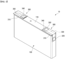
- FIG. 1 is a perspective view of a secondary battery 10 according to the present invention
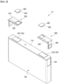
- FIG. 2 is a perspective view of a coupling structure of a secondary battery 10 and a terminal structure 300 according to the present invention.
- the present invention relates to a secondary battery 10, and in particular to a unidirectional, prismatic secondary battery 10 having a pair of terminals, namely a positive electrode terminal 122 and a negative electrode terminal 124, spaced apart on the upper face of a battery case 100 having a hexahedral shape.
- the prismatic secondary battery 10 shown in the drawings is an example, and the ratio of width to length and height may vary, and for ease of explanation, the orientation of the front and rear and up and down and left and right will be referred to with reference to the attached drawings.
- one side of the battery case 100 on which the positive electrode terminal 122 and the negative electrode terminal 124 are disposed is called the upper face, and the opposite side facing it is called the lower surface.
- the secondary battery 10 of the present invention includes a terminal structure 300.
- the terminal structure 300 is a right-angled, bent structure that couples to at least one of the upper face edges of the battery case 100, and it includes a terminal body 310 and an extension terminal 320.
- Terminal body 310 refers to a body of the terminal structure 300 that couples to the upper face of the battery case 100 and a side extending from the upper face while enclosing the positive electrode terminal 122 or the negative electrode terminal 124 from being exposed to the outside.
- the drawings illustrate an example where the terminal structure 300 is coupled to both the positive electrode terminal 122 and the negative electrode terminal 124, depending on the embodiment, the terminal structure 300 may optionally be coupled to only one of the positive electrode terminal 122 and the negative electrode terminal 124.
- the extension terminal 320 corresponds to a connection terminal that is electrically connected to the positive electrode terminal 122 or the negative electrode terminal 124 and extends to the side of the terminal body 310. In other words, since the positive electrode terminal 122 or the negative electrode terminal 124 is not exposed and is enclosed by the terminal body 310, the extension terminal 320 functions as a new positive electrode terminal or negative electrode terminal relocated to the side of the battery case 100 rather than the upper face.
- the terminal body 310 is made of an insulating material, such as an electrically insulating resin or rubber material, thus the positive electrode terminal 122 or negative electrode terminal 124 covered by the terminal body is in an inactive state, electrically isolated from the outside environment.
- the existing positive electrode terminal 122 or negative electrode terminal 124 no longer functions as a connection terminal, and the extension terminal 320 on the terminal structure 300 functions as a new positive electrode terminal or negative electrode terminal.
- the secondary battery 10 of the present invention can freely change the position of the positive electrode terminal 122 and the negative electrode terminal 124, which are disposed together on the upper face of the battery case 100, and the arrangement structure of the electrode terminal 120 without any design change by simply applying the terminal structure 300. Therefore, the present invention can easily change the position of the positive electrode terminal 122 and/or the negative electrode terminal 124 by adding the terminal structure 300 for a secondary battery of the same form factor, thereby reducing the production cost of various prismatic secondary batteries.
- the positive electrode terminal 122 and/or the negative electrode terminal 124 are electrically connected to an extension wire 330 via an extension terminal 320, wherein the extension wire 330 extending to the extension terminal 320 forms a joint part 340 with respect to the positive electrode terminal 122 and/or the negative electrode terminal 124, wherein the joint part 340 provides a mechanically and electrically rigid connection between the extension wire 330 and the electrode terminal 120.
- the joint part 340 may be formed by welding.
- the extension wire 330 is not exposed to the outside of the terminal body 310.
- the extension wire 330 may be embedded in the terminal body 310 of an electrically insulating resin material by manufacturing techniques such as insert molding.
- the joint part 340 is also electrically insulated from the outside.
- the external insulation of the joint part 340 may be provided by at least one of an insulating cover, an insulating tape, and a curable insulating layer.
- a curable insulating layer here refers to an insulating layer formed by curing after a flowable insulating resin is applied to the joint part 340, and FIG. 1 and FIG. 2 show a configuration in which a film-like insulating tape 350 having an adhesive layer 352 insulates the joint part 340.
- the terminal structure 300 is secured to the positive electrode terminal 122 and the negative electrode terminal 124 by a joint part 340 formed by welding, and since the terminal structure 300 secured by the joint part 340 has many structural degrees of freedom, the terminal structure 300 may have problems if the secondary battery 10 of the present invention is subjected to continuous vibration. For example, if the secondary battery 10 of the present invention is applied to an electric automobile and placed in an environment subject to constant vibration, problems such as breakage of the terminal structure 300 bonded to the battery case 100 or weld degradation at the joint part 340 may occur.
- the secondary battery 10 of the present invention is configured to form a concave or recessed surface 130 on a side of the battery case 100 to improve the support structure of the terminal structure 300, and the side of the terminal structure 300 is configured to be seated in the concave surface 130.
- the concave surface 130 formed on the side of the battery case 100 has a shape corresponding to the side of the terminal structure 300. Accordingly, when the sides of the terminal structure 300 are seated within the concave surface 130, the side edges of the terminal structure 300 are supported by contacting the stepped edges of the concave surface 130.
- the stepped edges may also be referred to as the lips formed by the recessed surface and surrounding the surface.
- This additional support structure of the terminal structure 300 by the concave surface 130 limits the forward and backward degrees of freedom of the terminal structure 300, based on the drawings.
- the joint part 340 would have to bear all of the disturbances acting on the terminal structure 300, but the limited degrees of freedom provided by the concave surface 130 reduces the degrees of freedom of the terminal structure 300 that the joint part 340 must bear, thereby greatly reducing the possibility of problems such as welding degradation at the joint part 340 and improving the vibration resistance of the terminal structure 300 attached to the battery case 100.
- FIG. 3 and FIG. 4 illustrate a modified embodiment of a support structure between the concave surface 130 of the battery case 100 and the terminal structure 300.
- the side edges of the terminal structure 300 and the edges of the concave surface 130 are interconnected by a dovetail 400 structure.
- the dovetail 400 structure refers to a structure in which two members are interlocked by the corners of a non-equilateral square and are strongly bound together to prevent them from falling apart in a particular direction.
- the concave surface 130 on the side of the battery case 100 has a sloping surface with a greater width at the bottom in a vertical cross-section of the concave surface 130, and the sides of the terminal structure 300 are correspondingly shaped in a complementary manner (in the form of a sloping surface opposite to the sloping direction of the concave surface 130). Accordingly, the sides of the terminal structure 300 are slidingly coupled to each other along the height direction of the battery case 100 with respect to the concave surface 130.
- the degrees of freedom of the terminal structure 300 are further restricted.
- the terminal structure 300 can slidably move in only one direction, the height direction, with respect to the battery case 100, which further reduces the load that the joint part 340 must bear, further improving the support structure of the terminal structure 300.
- FIG. 5 is a drawing illustrating a secondary battery 10 according to a second embodiment of the present invention, wherein concave (or recessed) beading parts 140 are formed on opposite front and rear surfaces of the battery case 100, respectively. Furthermore, corresponding to the beading parts 140 formed on the front and rear surfaces of the battery case 100, the upper face corners of the terminal structure 300 are provided with protrusions 312 that are inserted into the beading parts 140.
- the side edges of the terminal structure 300 contact the stepped edges of the concave surface 130 while the upper face edge protrusions 312 of the terminal structure 300 are inserted into the beading part 140, thus ensuring that the terminal structure 300 is doubly supported against the battery case 100.
- the terminal structure 300 is similar in that the degrees of freedom of the terminal structure 300are limited in two directions, the difference being that the direction in which the degrees of freedom of the terminal structure 300 are limited is different from the dovetail 400 structure.
- the protrusions 312 of the terminal structure 300 are slidingly coupled to each other along the width direction of the battery case 100 with respect to the beading part 140, as shown in FIG. 6 , thereby limiting the degree of freedom of the terminal structure 300 from moving along the height direction of the battery case 100 by the coupling of the beading part 140 and the protrusions 312.
- the second embodiment further reduces the load that must be bearing by the joint part 340, and thus provides a stronger support structure for the terminal structure 300.
- the beading parts 140 formed on each of the front and rear surfaces of the battery case 100 may also function as a means of compressing the surface of the electrode assembly 200 housed within the battery case 100, as shown in FIG. 7 .
- the beading part 140 forms a concave surface 130 in the form of a thin line, and the beading part 140, which forms the concave surface 130 toward the interior of the battery case 100, has a depth that presses against the surface of the electrode assembly 200 housed inside the battery case 100.
- the beading part 140 is in the form of a thin line, it has a very small effect on the capacity of the prismatic secondary battery 10, even though it forms a concave surface 130 inwardly of the battery case 100. In other words, the beading part 140 has a very limited effect on the capacity or size of the essential components of the prismatic secondary battery 10 that are housed inside the battery case 100, such as the electrode assembly 200 and the electrolyte, etc.
- beading parts 140 formed along the front and rear perimeter of the cell case 100 compress against the surface of the electrode assembly 200 in both directions.
- the electrode assembly 200 having a gap with respect to the battery case 100 is pressed and fixed in both directions by a pair of opposing beading parts 140, thereby improving the support structure of the electrode assembly 200, and thus suppressing the slip phenomenon that causes the electrode assembly 200 to move during use.
- the fluidity of the electrode assembly 200 is restricted by the beading part 140, thereby preventing various problems such as shorts or tabs tearing due to electrical contact caused by slip phenomena, which greatly improves the safety of the prismatic secondary battery 10.
- the beading part 140 can compress the surface of the negative electrode 210 of the electrode assembly 200 housed inside the battery case 100.
- the electrode assembly 200 may be formed with the negative electrode 210 larger than the positive electrode 214 so that the negative electrode 210 surface covers the surface of the positive electrode 214. In other words, the surface of the negative electrode 210 covers the surface of the positive electrode 214 so that the positive electrode 214 is not exposed.
- the negative electrode 210 is advantageous from a safety perspective. This takes into account the N/P ratio, which is the ratio of the capacity of the negative electrode 210 to the positive electrode 214. In a lithium-ion secondary battery using a graphite negative electrode, the capacity of the negative electrode 210 must be larger than the positive electrode 214 to prevent lithium precipitation from the negative electrode 210 during overcharge.
- the electrode assembly 200 may be formed with the negative electrode 210 being larger than the positive electrode 214. It is also preferred that the side of the negative electrode 210 that is directly pressed by the beading part 140 across the separator 212 is the negative electrode 210 because of the higher structural stability of the negative electrode compared to the positive electrode.
- FIG. 8 is a front view of the prismatic secondary battery 10, wherein the electrode assembly 200 housed within the battery case 100 is represented by a silver line.
- a beading part 140 presses against the surface of the negative electrode 210, where the beading part 140 is formed at a position spaced apart from the electrode tab 220 of the electrode assembly 200.
- the beading part 140 presses against the surface of the negative electrode 210 of the electrode assembly 200, it may support a cathode active material-coated retaining member, or a cathode non-active material-coated plain member. If the beading part 140 is compressing the cathode plain, it is preferable to perform a notching operation on the cathode plain to support a downward region some distance from the formed negative electrode tab 222. This is because creating stress on the electrode tabs 220 by allowing the beading part 140 to directly compress the electrode tabs 220, particularly the negative electrode tab 222, is likely to damage the electrode tabs 220. Additionally, the beading part 140 may be formed adjacent to the cap plate 110 forming the upper face of the battery case 100 to compress the top of the electrode assembly 200 housed within the battery case 100.
- the beading parts 140 are formed on the front and rear sides that have the longest widthwise lengths of the front, rear, and left and right perimeters of the battery case 100, the beading parts 140 are of sufficient length to firmly support the electrode assembly 200. Furthermore, since the support structure of the terminal structure 300 is also improved by the insertion of the protrusions 312 of the terminal structure 300 with respect to the beading part 140, the second embodiment of the present invention significantly improves the structural stability of the prismatic secondary battery 10 by the beading part 140.
Landscapes
- Chemical & Material Sciences (AREA)
- Chemical Kinetics & Catalysis (AREA)
- Electrochemistry (AREA)
- General Chemical & Material Sciences (AREA)
- Engineering & Computer Science (AREA)
- Manufacturing & Machinery (AREA)
- Connection Of Batteries Or Terminals (AREA)
- Sealing Battery Cases Or Jackets (AREA)
Abstract
Description
- This application claims the benefit of priority based on
Korean Patent Application No. 10-2022-0141685, filed on October 28, 2022 - The present invention relates to a secondary battery, and more particularly to a prismatic secondary battery having an improved terminal structure in which the arrangement structure of the positive and/or negative electrode terminals can be easily and reliably varied.
- Unlike primary batteries, secondary batteries can be recharged and have been researched and developed in recent years due to their potential for miniaturization and large capacity. The demand for the secondary battery as an energy source is increasing rapidly due to the technological development and increasing demand for mobile devices, electric vehicles, and energy storage systems, which are emerging in response to the need for environmental protection.
- Secondary batteries are categorized into coin batteries, cylindrical batteries, prismatic batteries, and pouch batteries based on the shape of the battery case. In the secondary battery, the electrode assembly mounted inside the battery case is a charging and discharging power generation element consisting of a stacked structure of electrodes and separators.
- Electrode assemblies can be broadly categorized into (1) Jellyroll type, which is wound with a separator between the positive and negative electrodes of an active material-coated sheet, (2) Stack type, in which a plurality of positive and negative electrodes is sequentially stacked with an interposed separator, and (3) Stack & Folding type, in which stacked unit cells are wound with a long length of separator film.
- Among the various types of secondary batteries, prismatic secondary batteries are mostly composed of positive and negative electrode terminals arranged together on one side, or one on each of the two opposing sides. The arrangement of the positive and negative electrode terminals is determined by the design specifications of various devices containing prismatic secondary batteries, and it is difficult to design the arrangement structure of the positive and negative electrode terminals separately in the same form factor according to these design specifications.
- The present invention is directed to providing a new prismatic secondary battery in which the arrangement structure of the positive and negative electrode terminals provided in the prismatic secondary battery can be easily changed and manufactured without any design changes.
- In addition, the present invention has another objective to provide a prismatic secondary battery that can stably maintain the changed arrangement even after the arrangement structure of the positive and negative electrode terminals is changed.
- However, the technical problem to be solved by the present invention is not limited to the above-described problem, and other problems not mentioned can be clearly understood by a person skilled in the art from the description of the invention described below.
- A secondary battery according to the invention, in one example, including a secondary battery having positive and negative electrode terminals spaced apart on a upper face of a battery case having a hexahedral shape, and a terminal body in the form of a bend engaging an upper face of the battery case and a side extending from the upper face of the battery case while enclosing the positive or negative electrode terminals from being exposed, a terminal structure including an extension terminal electrically connected to the positive or negative electrode terminals and exposed on a side of the terminal structure, the side of the terminal structure seated in a concave surface formed in a side of the battery case.
- In one embodiment of the invention, the terminal body is made of an insulating material, whereby the positive or negative electrode is electrically isolated from the outside.
- Further, the concave surface is formed in a shape corresponding to a side of the terminal structure, and the side edges of the terminal structure are supported in contact with the stepped edges of the concave surface.
- Furthermore, the side edges of the terminal structure and the edges of the concave surface may be interconnected by a dovetail structure.
- Accordingly, the sides of the terminal structure may be slidably engaged with respect to the concave surface.
- On the other hand, according to another embodiment of the present invention, opposite front and rear faces of the battery case may each be formed with concave beading parts, and upper face edges of the terminal structure may be provided with protrusions inserted into the beading parts.
- A side edge of the terminal structure contacts a stepped edge of the concave surface, while at the same time a protrusion of the terminal structure is inserted into the beading part, whereby the terminal structure is supported against the battery case.
- In addition, the protrusions of the terminal structure may slidably engage and interlock with each other with respect to the beading part.
- Further, the beading parts may press against the surface of the electrode assembly housed within the battery case.
- The beading part may be formed at a location spaced apart from the electrode tabs of the electrode assembly housed inside the battery case, such as adjacent to the cap plate to press against the top of the electrode assembly housed inside the battery case.
- According to the secondary battery of the present invention, by applying a terminal structure with a simple structure, it is possible to easily change the terminal arrangement from a unidirectional secondary battery to a bidirectional secondary battery, and the support structure of the terminal structure is strengthened to prevent problems such as breakage of the terminal structure bonded to the battery case and welding deterioration due to vibration during automobile operation.
- In addition, the concave beading parts formed on the front and rear surfaces of the battery case to limit the degree of freedom of the terminal structure can compress and support the surface of the electrode assembly housed inside, thereby improving the support structure of the electrode assembly, and thus greatly improving the safety of the secondary battery.
- However, the technical effects that can be obtained through the present invention is not limited to the above-described effects, and other effects not mentioned can be clearly understood by a person skilled in the art from the description of the invention described below.
- Because the following drawings attached to the present specification illustrate exemplary embodiments of the present invention and serve to facilitate understanding of the technical idea of the present invention together with the detailed description of the invention described below, the present invention should not be limitedly interpreted on the basis of the drawings.
-
FIG. 1 is a perspective view illustrating a secondary battery according to the present invention. -
FIG. 2 is a perspective view illustrating the combined structure of a secondary battery and terminal structure according to the present invention. -
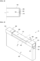
FIG. 3 is a diagram illustrating an embodiment in which the concave surface of the battery case and the terminal structure are coupled in a dovetail structure. -
FIG. 4 is a cross-sectional view along line "A-A" inFIG. 3 . -
FIG. 5 is a perspective view illustrating a secondary battery according to another embodiment of the present invention. -
FIG. 6 is a perspective view illustrating the combined structure of the secondary battery and terminal structure according to the embodiment ofFIG. 5 . -
FIG. 7 is a cross-sectional view along line "B-B" inFIG. 5 . -
FIG. 8 is a front view of the secondary battery ofFIG. 5 . - The present invention may have various modifications and various embodiments, and thus specific embodiments thereof will be described in detail below.
- However, it should be understood that the present invention is not limited to the specific embodiments, and includes all modifications, equivalents, or alternatives within the spirit and technical scope of the present invention.
- The terms "comprise," "include," and "have" used herein designate the presence of characteristics, numbers, steps, actions, components, or members described in the specification or a combination thereof, and it should be understood that the possibility of the presence or addition of one or more other characteristics, numbers, steps, actions, components, members, or a combination thereof is not excluded in advance.
- In addition, in the present invention, when a part of a layer, film, region, plate, or the like is disposed "on" another part, this includes not only a case in which one part is disposed "directly on" another part, but a case in which still another part is interposed therebetween. In contrast, when a part of a layer, film, region, plate, or the like is disposed "under" another part, this includes not only a case in which one part is disposed "directly under" another part, but a case in which still another part is interposed therebetween. In addition, in the present application, "on" may include not only a case of being disposed on an upper portion but also a case of being disposed on a lower portion.
- A secondary battery according to the present invention, wherein the positive and negative electrode terminals are spaced apart on an upper face of a battery case having a hexahedral shape, the secondary battery including a terminal body in the form of a bend that engages the upper face of the battery case and a side surface extending from the upper face of the battery case while enclosing the positive or negative electrode terminals from being exposed, and a terminal structure including an extension terminal electrically connected to the positive or negative electrode terminals and exposed on a side surface of the terminal body.
- Further, a side of the terminal structure is received in a concave surface formed in a side of the battery case.
- Accordingly, the secondary battery of the present invention including the terminal structure can freely change the positions of the positive and negative electrode terminals arranged on the upper face of the battery case to match the user's needs without any design changes by simply applying the terminal structure, and thereby reduce the production cost of prismatic secondary batteries by eliminating the need to design a unidirectional secondary battery into a bidirectional secondary battery.
- In addition, the prismatic secondary battery of the present invention has a limited degree of freedom of movement as the terminal structure is supported by being seated in a concave surface formed in the battery case, thereby preventing problems such as breakage of the terminal structure bonded to the battery case or welding deterioration due to vibration during automobile operation.
- Hereinafter, specific embodiments of a secondary battery of the present invention will be described in detail with reference to the accompanying drawings. For reference, the directions of front, back, up, down, left, and right used in the following description to designate relative positions are for the purpose of understanding the invention and refer to the directions shown in the drawings unless otherwise specified.
-
FIG. 1 is a perspective view of asecondary battery 10 according to the present invention, andFIG. 2 is a perspective view of a coupling structure of asecondary battery 10 and aterminal structure 300 according to the present invention. - Referring to
FIG. 1 andFIG. 2 , the present invention relates to asecondary battery 10, and in particular to a unidirectional, prismaticsecondary battery 10 having a pair of terminals, namely apositive electrode terminal 122 and anegative electrode terminal 124, spaced apart on the upper face of abattery case 100 having a hexahedral shape. Here, the prismaticsecondary battery 10 shown in the drawings is an example, and the ratio of width to length and height may vary, and for ease of explanation, the orientation of the front and rear and up and down and left and right will be referred to with reference to the attached drawings. For example, one side of thebattery case 100 on which thepositive electrode terminal 122 and thenegative electrode terminal 124 are disposed is called the upper face, and the opposite side facing it is called the lower surface. - The
secondary battery 10 of the present invention includes aterminal structure 300. Theterminal structure 300 is a right-angled, bent structure that couples to at least one of the upper face edges of thebattery case 100, and it includes aterminal body 310 and anextension terminal 320. -
Terminal body 310 refers to a body of theterminal structure 300 that couples to the upper face of thebattery case 100 and a side extending from the upper face while enclosing thepositive electrode terminal 122 or thenegative electrode terminal 124 from being exposed to the outside. Although the drawings illustrate an example where theterminal structure 300 is coupled to both thepositive electrode terminal 122 and thenegative electrode terminal 124, depending on the embodiment, theterminal structure 300 may optionally be coupled to only one of thepositive electrode terminal 122 and thenegative electrode terminal 124. - The
extension terminal 320 corresponds to a connection terminal that is electrically connected to thepositive electrode terminal 122 or thenegative electrode terminal 124 and extends to the side of theterminal body 310. In other words, since thepositive electrode terminal 122 or thenegative electrode terminal 124 is not exposed and is enclosed by theterminal body 310, theextension terminal 320 functions as a new positive electrode terminal or negative electrode terminal relocated to the side of thebattery case 100 rather than the upper face. - Furthermore, the
terminal body 310 is made of an insulating material, such as an electrically insulating resin or rubber material, thus thepositive electrode terminal 122 ornegative electrode terminal 124 covered by the terminal body is in an inactive state, electrically isolated from the outside environment. In other words, in thesecondary battery 10 to which theterminal structure 300 is coupled, the existingpositive electrode terminal 122 ornegative electrode terminal 124 no longer functions as a connection terminal, and theextension terminal 320 on theterminal structure 300 functions as a new positive electrode terminal or negative electrode terminal. - Accordingly, the
secondary battery 10 of the present invention can freely change the position of thepositive electrode terminal 122 and thenegative electrode terminal 124, which are disposed together on the upper face of thebattery case 100, and the arrangement structure of theelectrode terminal 120 without any design change by simply applying theterminal structure 300. Therefore, the present invention can easily change the position of thepositive electrode terminal 122 and/or thenegative electrode terminal 124 by adding theterminal structure 300 for a secondary battery of the same form factor, thereby reducing the production cost of various prismatic secondary batteries. - In one embodiment of the present invention, the
positive electrode terminal 122 and/or thenegative electrode terminal 124 are electrically connected to anextension wire 330 via anextension terminal 320, wherein theextension wire 330 extending to theextension terminal 320 forms ajoint part 340 with respect to thepositive electrode terminal 122 and/or thenegative electrode terminal 124, wherein thejoint part 340 provides a mechanically and electrically rigid connection between theextension wire 330 and theelectrode terminal 120. For example, thejoint part 340 may be formed by welding. - The
extension wire 330 is not exposed to the outside of theterminal body 310. For example, theextension wire 330 may be embedded in theterminal body 310 of an electrically insulating resin material by manufacturing techniques such as insert molding. Thejoint part 340 is also electrically insulated from the outside. The external insulation of thejoint part 340 may be provided by at least one of an insulating cover, an insulating tape, and a curable insulating layer. - A curable insulating layer here refers to an insulating layer formed by curing after a flowable insulating resin is applied to the
joint part 340, andFIG. 1 andFIG. 2 show a configuration in which a film-likeinsulating tape 350 having anadhesive layer 352 insulates thejoint part 340. - Basically, the
terminal structure 300 is secured to thepositive electrode terminal 122 and thenegative electrode terminal 124 by ajoint part 340 formed by welding, and since theterminal structure 300 secured by thejoint part 340 has many structural degrees of freedom, theterminal structure 300 may have problems if thesecondary battery 10 of the present invention is subjected to continuous vibration. For example, if thesecondary battery 10 of the present invention is applied to an electric automobile and placed in an environment subject to constant vibration, problems such as breakage of theterminal structure 300 bonded to thebattery case 100 or weld degradation at thejoint part 340 may occur. - The
secondary battery 10 of the present invention is configured to form a concave or recessedsurface 130 on a side of thebattery case 100 to improve the support structure of theterminal structure 300, and the side of theterminal structure 300 is configured to be seated in theconcave surface 130. - Specifically, referring to
FIG. 1 andFIG. 2 , theconcave surface 130 formed on the side of thebattery case 100 has a shape corresponding to the side of theterminal structure 300. Accordingly, when the sides of theterminal structure 300 are seated within theconcave surface 130, the side edges of theterminal structure 300 are supported by contacting the stepped edges of theconcave surface 130. The stepped edges may also be referred to as the lips formed by the recessed surface and surrounding the surface. - This additional support structure of the
terminal structure 300 by theconcave surface 130 limits the forward and backward degrees of freedom of theterminal structure 300, based on the drawings. In the absence of theconcave surface 130, thejoint part 340 would have to bear all of the disturbances acting on theterminal structure 300, but the limited degrees of freedom provided by theconcave surface 130 reduces the degrees of freedom of theterminal structure 300 that thejoint part 340 must bear, thereby greatly reducing the possibility of problems such as welding degradation at thejoint part 340 and improving the vibration resistance of theterminal structure 300 attached to thebattery case 100. -
FIG. 3 andFIG. 4 illustrate a modified embodiment of a support structure between theconcave surface 130 of thebattery case 100 and theterminal structure 300. Referring to the figures, the side edges of theterminal structure 300 and the edges of theconcave surface 130 are interconnected by adovetail 400 structure. Thedovetail 400 structure refers to a structure in which two members are interlocked by the corners of a non-equilateral square and are strongly bound together to prevent them from falling apart in a particular direction. - As shown in
FIG. 3 andFIG. 4 , theconcave surface 130 on the side of thebattery case 100 has a sloping surface with a greater width at the bottom in a vertical cross-section of theconcave surface 130, and the sides of theterminal structure 300 are correspondingly shaped in a complementary manner (in the form of a sloping surface opposite to the sloping direction of the concave surface 130). Accordingly, the sides of theterminal structure 300 are slidingly coupled to each other along the height direction of thebattery case 100 with respect to theconcave surface 130. - When the side edges of the
terminal structure 300 and the edges of theconcave surface 130 are interconnected by thedovetail 400 structure, the degrees of freedom of theterminal structure 300 are further restricted. In other words, theterminal structure 300 can slidably move in only one direction, the height direction, with respect to thebattery case 100, which further reduces the load that thejoint part 340 must bear, further improving the support structure of theterminal structure 300. -
FIG. 5 is a drawing illustrating asecondary battery 10 according to a second embodiment of the present invention, wherein concave (or recessed)beading parts 140 are formed on opposite front and rear surfaces of thebattery case 100, respectively. Furthermore, corresponding to thebeading parts 140 formed on the front and rear surfaces of thebattery case 100, the upper face corners of theterminal structure 300 are provided withprotrusions 312 that are inserted into thebeading parts 140. - According to this second embodiment, the side edges of the
terminal structure 300 contact the stepped edges of theconcave surface 130 while the upperface edge protrusions 312 of theterminal structure 300 are inserted into thebeading part 140, thus ensuring that theterminal structure 300 is doubly supported against thebattery case 100. - Compared to the
dovetail 400 structure of the first embodiment described above, theterminal structure 300 is similar in that the degrees of freedom of the terminal structure 300are limited in two directions, the difference being that the direction in which the degrees of freedom of theterminal structure 300 are limited is different from thedovetail 400 structure. In other words, in the second embodiment, theprotrusions 312 of theterminal structure 300 are slidingly coupled to each other along the width direction of thebattery case 100 with respect to thebeading part 140, as shown inFIG. 6 , thereby limiting the degree of freedom of theterminal structure 300 from moving along the height direction of thebattery case 100 by the coupling of thebeading part 140 and theprotrusions 312. As a result, the second embodiment further reduces the load that must be bearing by thejoint part 340, and thus provides a stronger support structure for theterminal structure 300. - Here, in addition to functioning as a support for the
terminal structure 300, thebeading parts 140 formed on each of the front and rear surfaces of thebattery case 100 may also function as a means of compressing the surface of theelectrode assembly 200 housed within thebattery case 100, as shown inFIG. 7 . - The
beading part 140 forms aconcave surface 130 in the form of a thin line, and thebeading part 140, which forms theconcave surface 130 toward the interior of thebattery case 100, has a depth that presses against the surface of theelectrode assembly 200 housed inside thebattery case 100. - Because the
beading part 140 is in the form of a thin line, it has a very small effect on the capacity of the prismaticsecondary battery 10, even though it forms aconcave surface 130 inwardly of thebattery case 100. In other words, thebeading part 140 has a very limited effect on the capacity or size of the essential components of the prismaticsecondary battery 10 that are housed inside thebattery case 100, such as theelectrode assembly 200 and the electrolyte, etc. - As shown in
FIG. 7 ,beading parts 140 formed along the front and rear perimeter of thecell case 100 compress against the surface of theelectrode assembly 200 in both directions. In other words, theelectrode assembly 200 having a gap with respect to thebattery case 100 is pressed and fixed in both directions by a pair of opposingbeading parts 140, thereby improving the support structure of theelectrode assembly 200, and thus suppressing the slip phenomenon that causes theelectrode assembly 200 to move during use. - As a result, the fluidity of the
electrode assembly 200 is restricted by thebeading part 140, thereby preventing various problems such as shorts or tabs tearing due to electrical contact caused by slip phenomena, which greatly improves the safety of the prismaticsecondary battery 10. - Furthermore, the
beading part 140 can compress the surface of thenegative electrode 210 of theelectrode assembly 200 housed inside thebattery case 100. Theelectrode assembly 200 may be formed with thenegative electrode 210 larger than thepositive electrode 214 so that thenegative electrode 210 surface covers the surface of thepositive electrode 214. In other words, the surface of thenegative electrode 210 covers the surface of thepositive electrode 214 so that thepositive electrode 214 is not exposed. - In the
electrode assembly 200, forming thenegative electrode 210 larger than thepositive electrode 214 is advantageous from a safety perspective. This takes into account the N/P ratio, which is the ratio of the capacity of thenegative electrode 210 to thepositive electrode 214. In a lithium-ion secondary battery using a graphite negative electrode, the capacity of thenegative electrode 210 must be larger than thepositive electrode 214 to prevent lithium precipitation from thenegative electrode 210 during overcharge. - In this regard, it may be desirable to maintain an N/P ratio of approximately 1.12 for the safety of the
secondary battery 10, whereby theelectrode assembly 200 may be formed with thenegative electrode 210 being larger than thepositive electrode 214. It is also preferred that the side of thenegative electrode 210 that is directly pressed by thebeading part 140 across theseparator 212 is thenegative electrode 210 because of the higher structural stability of the negative electrode compared to the positive electrode. -
FIG. 8 is a front view of the prismaticsecondary battery 10, wherein theelectrode assembly 200 housed within thebattery case 100 is represented by a silver line. Abeading part 140 presses against the surface of thenegative electrode 210, where thebeading part 140 is formed at a position spaced apart from theelectrode tab 220 of theelectrode assembly 200. - As the
beading part 140 presses against the surface of thenegative electrode 210 of theelectrode assembly 200, it may support a cathode active material-coated retaining member, or a cathode non-active material-coated plain member. If thebeading part 140 is compressing the cathode plain, it is preferable to perform a notching operation on the cathode plain to support a downward region some distance from the formednegative electrode tab 222. This is because creating stress on theelectrode tabs 220 by allowing thebeading part 140 to directly compress theelectrode tabs 220, particularly thenegative electrode tab 222, is likely to damage theelectrode tabs 220. Additionally, thebeading part 140 may be formed adjacent to thecap plate 110 forming the upper face of thebattery case 100 to compress the top of theelectrode assembly 200 housed within thebattery case 100. - Moreover, because the
beading parts 140 are formed on the front and rear sides that have the longest widthwise lengths of the front, rear, and left and right perimeters of thebattery case 100, thebeading parts 140 are of sufficient length to firmly support theelectrode assembly 200. Furthermore, since the support structure of theterminal structure 300 is also improved by the insertion of theprotrusions 312 of theterminal structure 300 with respect to thebeading part 140, the second embodiment of the present invention significantly improves the structural stability of the prismaticsecondary battery 10 by thebeading part 140. - As above, the present invention has been described in more detail through the drawings and embodiments. However, since the configuration described in the drawings or embodiments described herein is merely one embodiment of the present invention and do not represent the overall technical spirit of the invention, it should be understood that the invention covers various equivalents, modifications, and substitutions at the time of filing of this application.
-
- 10: secondary battery
- 100: battery case
- 110: cap plate
- 120: electrode terminal
- 122: positive electrode terminal
- 124: negative electrode terminal
- 130: concave surface
- 140: beading part
- 200: electrode structure
- 210: negative electrode
- 212: separator
- 214: positive electrode
- 220: electrode tab
- 222: negative electrode tab
- 224: positive electrode tab
- 300: terminal structure
- 310: terminal body
- 312: protrusion
- 330: extension wire
- 340: insulating tape
- 352: bonding layer
- 400: dovetail
Claims (11)
- A secondary battery comprising:positive and negative electrode terminals spaced apart on a first face of a hexahedral-shaped battery case; anda nonlinear terminal body contacting the first face of the battery case and a side of the battery case extending from the first face of the battery case while enclosing one of the positive or negative electrode terminals,a terminal structure including an extension terminal electrically connected to the one of the positive or negative electrode terminals, the extension terminal exposed on a side of the terminal structure;wherein the side of the terminal structure is seated in a recessed surface formed in the side of the battery case.
- The secondary battery of claim 1, wherein the terminal body is formed of an insulating material, whereby the one of the positive or negative electrode terminals is electrically isolated from ambient elements.
- The secondary battery of claim 1, wherein the recessed surface is formed in a shape corresponding to the side of the terminal structure, and side edges of the terminal structure are supported in contact with stepped edges of the recessed surface.
- The secondary battery of claim 3, wherein the side edges of the terminal structure and the stepped edges of the recessed surface are coupled by a dovetail structure.
- The secondary battery of claim 4, wherein the sides of the terminal structure are configured to be be slidably engaged with respect to the recessed surface.
- The secondary battery of claim 1, wherein opposing second and third faces of the battery case are formed with recessed beading parts, and
edges of the first face of the terminal structure include protrusions configured to be inserted into the beading parts. - The secondary battery of claim 6, wherein when a side edge of the terminal structure contacts a stepped edge of the recessed surface, a protrusion of the terminal structure is disposed within the beading part,
- The secondary battery of claim 7, wherein the protrusion of the terminal structure is configured to slidably engage and interlock with the recessed beading part.
- The secondary battery of claim 6, wherein the beading parts contact a surface of an electrode assembly housed within the battery case.
- The secondary battery of claim 9, wherein the beading parts are formed at a location spaced apart from electrode tabs of the electrode assembly housed inside the battery case.
- The secondary battery of claim 10, wherein the beading parts are adjacent to a cap plate to press against the electrode assembly housed inside the battery case.
Applications Claiming Priority (2)
| Application Number | Priority Date | Filing Date | Title |
|---|---|---|---|
| KR1020220141685A KR20240060271A (en) | 2022-10-28 | 2022-10-28 | Secondary battery having improved terminal structure |
| PCT/KR2023/016618 WO2024090979A1 (en) | 2022-10-28 | 2023-10-25 | Secondary battery having improved terminal structure |
Publications (2)
| Publication Number | Publication Date |
|---|---|
| EP4435960A1 true EP4435960A1 (en) | 2024-09-25 |
| EP4435960A4 EP4435960A4 (en) | 2025-03-26 |
Family
ID=90831333
Family Applications (1)
| Application Number | Title | Priority Date | Filing Date |
|---|---|---|---|
| EP23883084.8A Pending EP4435960A4 (en) | 2022-10-28 | 2023-10-25 | Secondary battery having improved terminal structure |
Country Status (6)
| Country | Link |
|---|---|
| US (1) | US20250070423A1 (en) |
| EP (1) | EP4435960A4 (en) |
| JP (1) | JP7819432B2 (en) |
| KR (1) | KR20240060271A (en) |
| CN (1) | CN118476119A (en) |
| WO (1) | WO2024090979A1 (en) |
Families Citing this family (1)
| Publication number | Priority date | Publication date | Assignee | Title |
|---|---|---|---|---|
| JP7772024B2 (en) * | 2023-05-12 | 2025-11-18 | トヨタ自動車株式会社 | Energy storage cells and modules |
Family Cites Families (16)
| Publication number | Priority date | Publication date | Assignee | Title |
|---|---|---|---|---|
| JP2003157827A (en) | 2001-11-26 | 2003-05-30 | Auto Network Gijutsu Kenkyusho:Kk | Battery connection method and structure |
| JP2006107922A (en) | 2004-10-05 | 2006-04-20 | Sanyo Electric Co Ltd | Battery pack |
| KR100659853B1 (en) * | 2005-04-29 | 2006-12-19 | 삼성에스디아이 주식회사 | Secondary Battery Having Beading Part and Manufacturing Method Thereof |
| KR20120124026A (en) * | 2011-05-02 | 2012-11-12 | 에스비리모티브 주식회사 | Rechargeable battery |
| KR101715963B1 (en) | 2012-04-06 | 2017-03-27 | 삼성에스디아이 주식회사 | Secondary bttery |
| KR101627631B1 (en) * | 2012-04-12 | 2016-06-07 | 삼성에스디아이 주식회사 | Rechargeable battery and module thereof |
| JP5480947B2 (en) * | 2012-10-02 | 2014-04-23 | 日本航空電子工業株式会社 | Assembly |
| KR20140094207A (en) * | 2013-01-21 | 2014-07-30 | 삼성에스디아이 주식회사 | Rechargeable battery module |
| JP2015179578A (en) | 2014-03-18 | 2015-10-08 | 株式会社リチウムエナジージャパン | Storage element and power supply module |
| KR101802864B1 (en) * | 2015-01-15 | 2017-11-29 | 주식회사 엘지화학 | Bus Bar Assembly Having Low Contact Resistance and Battery Module Including the Same |
| KR102425219B1 (en) * | 2017-09-07 | 2022-07-26 | 삼성에스디아이 주식회사 | Secondary Battery |
| KR102578860B1 (en) | 2018-02-27 | 2023-09-13 | 삼성에스디아이 주식회사 | Rechargeable battery |
| CN113113738A (en) | 2021-03-24 | 2021-07-13 | 福建南平延平区南孚新能源科技有限公司 | Multi-tab battery |
| KR102896570B1 (en) | 2021-10-15 | 2025-12-04 | 컨템포러리 엠퍼렉스 테크놀로지 (홍콩) 리미티드 | Battery cell and its manufacturing method, manufacturing device, battery, electrical device |
| CN117280540A (en) * | 2022-02-09 | 2023-12-22 | 株式会社Lg新能源 | Secondary battery with improved terminal structure |
| KR20230171556A (en) | 2022-06-14 | 2023-12-21 | 주식회사 엘지에너지솔루션 | Secondary battery having improved terminal structure |
-
2022
- 2022-10-28 KR KR1020220141685A patent/KR20240060271A/en active Pending
-
2023
- 2023-10-25 WO PCT/KR2023/016618 patent/WO2024090979A1/en not_active Ceased
- 2023-10-25 JP JP2024539644A patent/JP7819432B2/en active Active
- 2023-10-25 CN CN202380015755.6A patent/CN118476119A/en active Pending
- 2023-10-25 EP EP23883084.8A patent/EP4435960A4/en active Pending
- 2023-10-25 US US18/726,198 patent/US20250070423A1/en active Pending
Also Published As
| Publication number | Publication date |
|---|---|
| CN118476119A (en) | 2024-08-09 |
| JP7819432B2 (en) | 2026-02-25 |
| KR20240060271A (en) | 2024-05-08 |
| US20250070423A1 (en) | 2025-02-27 |
| EP4435960A4 (en) | 2025-03-26 |
| JP2024545972A (en) | 2024-12-16 |
| WO2024090979A1 (en) | 2024-05-02 |
Similar Documents
| Publication | Publication Date | Title |
|---|---|---|
| US12243975B2 (en) | Method for manufacturing secondary battery and pouch for secondary battery | |
| US20220255201A1 (en) | Flexible battery | |
| KR101379957B1 (en) | A Stepwise Electrode Assembly, and a Battery Cell, Battery Pack and Device Comprising the Same | |
| KR100866767B1 (en) | Secondary battery safety member | |
| KR100905390B1 (en) | Pouch type secondary battery improves safety by preventing internal flow of electrode assembly | |
| KR101565115B1 (en) | Battery Pack and method for manufacturing the same | |
| US9786874B2 (en) | Electrode having round corner | |
| KR102066198B1 (en) | Battery pack | |
| EP3486967B1 (en) | Battery cell comprising electrode lead facing outer surface of electrode assembly | |
| KR20170135597A (en) | Battery module, battery pack comprising the battery module and vehicle comprising the battery pack | |
| US20250038380A1 (en) | Battery Module Having Insulation Pad With Extended Length, and Battery Pack and Vehicle Comprising Same | |
| US9431636B2 (en) | Rechargeable battery | |
| JP2024545874A (en) | Improved safety of rectangular secondary batteries | |
| EP4435960A1 (en) | Secondary battery having improved terminal structure | |
| JP7722059B2 (en) | battery pack | |
| KR101826862B1 (en) | Battery Pack Having Protection Module | |
| EP4518005A1 (en) | Terminal structure assembly integrally including busbar | |
| KR100877811B1 (en) | Secondary battery safety member with steps formed on both sides | |
| KR100858789B1 (en) | Improved safety electrochemical cell containing damping formed by thermal fusion of separator | |
| KR102576583B1 (en) | Bettery cell | |
| KR101994842B1 (en) | Electrode Plate Having Structure Capable of Maximizing Interior Space Occupancy for Secondary Battery, and Secondary Battery or Capacitor Comprising the Same | |
| EP4207408A1 (en) | Battery cell and battery module including the same | |
| EP4468507A1 (en) | Battery cell, battery module comprising battery cell, and battery pack comprising battery module | |
| KR20160115220A (en) | Electrode Assembly of Combination Structure | |
| KR20160133194A (en) | Electrode Assembly Including Electrodes Being Interconnected |
Legal Events
| Date | Code | Title | Description |
|---|---|---|---|
| STAA | Information on the status of an ep patent application or granted ep patent |
Free format text: STATUS: THE INTERNATIONAL PUBLICATION HAS BEEN MADE |
|
| PUAI | Public reference made under article 153(3) epc to a published international application that has entered the european phase |
Free format text: ORIGINAL CODE: 0009012 |
|
| STAA | Information on the status of an ep patent application or granted ep patent |
Free format text: STATUS: REQUEST FOR EXAMINATION WAS MADE |
|
| 17P | Request for examination filed |
Effective date: 20240621 |
|
| AK | Designated contracting states |
Kind code of ref document: A1 Designated state(s): AL AT BE BG CH CY CZ DE DK EE ES FI FR GB GR HR HU IE IS IT LI LT LU LV MC ME MK MT NL NO PL PT RO RS SE SI SK SM TR |
|
| A4 | Supplementary search report drawn up and despatched |
Effective date: 20250226 |
|
| RIC1 | Information provided on ipc code assigned before grant |
Ipc: H01M 50/547 20210101ALI20250220BHEP Ipc: H01M 50/103 20210101ALI20250220BHEP Ipc: H01M 50/588 20210101ALI20250220BHEP Ipc: H01M 50/567 20210101ALI20250220BHEP Ipc: H01M 50/55 20210101ALI20250220BHEP Ipc: H01M 50/557 20210101AFI20250220BHEP |
|
| STAA | Information on the status of an ep patent application or granted ep patent |
Free format text: STATUS: EXAMINATION IS IN PROGRESS |
|
| DAV | Request for validation of the european patent (deleted) | ||
| DAX | Request for extension of the european patent (deleted) | ||
| 17Q | First examination report despatched |
Effective date: 20260204 |