EP4435498A1 - Contact lens having multi-layered wavelength plate - Google Patents
Contact lens having multi-layered wavelength plate Download PDFInfo
- Publication number
- EP4435498A1 EP4435498A1 EP22896044.9A EP22896044A EP4435498A1 EP 4435498 A1 EP4435498 A1 EP 4435498A1 EP 22896044 A EP22896044 A EP 22896044A EP 4435498 A1 EP4435498 A1 EP 4435498A1
- Authority
- EP
- European Patent Office
- Prior art keywords
- wave plate
- contact lens
- plate layer
- layer
- wave
- Prior art date
- Legal status (The legal status is an assumption and is not a legal conclusion. Google has not performed a legal analysis and makes no representation as to the accuracy of the status listed.)
- Pending
Links
Images







Classifications
-
- G—PHYSICS
- G02—OPTICS
- G02C—SPECTACLES; SUNGLASSES OR GOGGLES INSOFAR AS THEY HAVE THE SAME FEATURES AS SPECTACLES; CONTACT LENSES
- G02C7/00—Optical parts
- G02C7/02—Lenses; Lens systems ; Methods of designing lenses
- G02C7/04—Contact lenses for the eyes
-
- G—PHYSICS
- G02—OPTICS
- G02B—OPTICAL ELEMENTS, SYSTEMS OR APPARATUS
- G02B5/00—Optical elements other than lenses
- G02B5/30—Polarising elements
- G02B5/3083—Birefringent or phase retarding elements
-
- G—PHYSICS
- G02—OPTICS
- G02C—SPECTACLES; SUNGLASSES OR GOGGLES INSOFAR AS THEY HAVE THE SAME FEATURES AS SPECTACLES; CONTACT LENSES
- G02C7/00—Optical parts
- G02C7/02—Lenses; Lens systems ; Methods of designing lenses
- G02C7/04—Contact lenses for the eyes
- G02C7/041—Contact lenses for the eyes bifocal; multifocal
- G02C7/042—Simultaneous type
-
- G—PHYSICS
- G02—OPTICS
- G02C—SPECTACLES; SUNGLASSES OR GOGGLES INSOFAR AS THEY HAVE THE SAME FEATURES AS SPECTACLES; CONTACT LENSES
- G02C7/00—Optical parts
- G02C7/02—Lenses; Lens systems ; Methods of designing lenses
- G02C7/04—Contact lenses for the eyes
- G02C7/041—Contact lenses for the eyes bifocal; multifocal
- G02C7/044—Annular configuration, e.g. pupil tuned
-
- G—PHYSICS
- G02—OPTICS
- G02C—SPECTACLES; SUNGLASSES OR GOGGLES INSOFAR AS THEY HAVE THE SAME FEATURES AS SPECTACLES; CONTACT LENSES
- G02C7/00—Optical parts
- G02C7/12—Polarisers
-
- G—PHYSICS
- G02—OPTICS
- G02C—SPECTACLES; SUNGLASSES OR GOGGLES INSOFAR AS THEY HAVE THE SAME FEATURES AS SPECTACLES; CONTACT LENSES
- G02C2202/00—Generic optical aspects applicable to one or more of the subgroups of G02C7/00
- G02C2202/16—Laminated or compound lenses
Definitions
- the present invention relates to a contact lens made of multilayer wave plates, and more particularly to a contact lens made of multilayer wave plates, the contact lens including two or more wave plates disposed between a corneal protective layer and lens surface layer of a contact lens to increase the number of focal points
- myopia and hyperopia Common conditions that cause poor vision include myopia and hyperopia. These conditions are usually due to an imbalance between the length of the eye and the focal point of the eye's optical elements. In myopic eyes, the focal points are set in front of the retinal plane, and in hyperopic eyes, the focal points are set in the back of the retinal plane.
- Myopia typically occurs because the axial length of the eye grows longer than the focal length of the eye's optical components, meaning the eye grows too long.
- Hyperopia typically occurs because the axial length of the eye is too short compared to the focal length of the eye's optical components, meaning the eye does not grow long enough.
- the ability to adjust focal length i.e., to focus on near and distant objects without relying on changes in focal length, can be improved by using intraocular multifocal lenses or contact lenses.
- Multifocal lenses have different focal lengths for near and far vision.
- the present invention has been made in view of the above problems, and it is one object of the present invention to provide a contact lens made of multilayer wave plates that are stacked to have complementary phases to each other in the contact lens, thereby being capable of increasing the number of focal points compared to an existing contact lens.
- a contact lens made of multilayer wave plates including: a lens surface layer; a corneal protective layer; and a wave plate layer in which two or more wave plates composed of a birefringent material are stacked and which is disposed between the lens surface layer and the corneal protective layer, and phases of neighboring wave plates in the wave plate layer have opposite phase signs so as to complement each other.
- light intensity at a position where focal points are formed may change accordingly.
- a thickness of the wave plate layer changes such that a light intensity at a position where one focal point is formed becomes 0, the number of focal points may change.
- positions where focal points are formed may change accordingly.
- a phase in the second wave plate may decrease as a phase in the first wave plate increases.
- the wave plate layer may be disposed in a central region of the corneal protective layer.
- the wave plate layer disposed in the central region may have a smaller area than the corneal protective layer.
- one wave plate layer may be disposed in a central region of the corneal protective layer, and another wave plate layer may be disposed in a peripheral region excluding the central region at a certain distance spaced from the central region in a direction outside the central region.
- the wave plate layer disposed in the peripheral region may be formed in an annular shape with a certain thickness.
- a plurality of wave plate layers may be formed in an annular shape with a certain thickness in the peripheral region, may have different radii, and may be arranged at a certain distance away from an adjacent wave plate layer.
- the wave plate layer may be disposed in a peripheral region excluding a central region of the corneal protective layer.
- the wave plate layer may be formed to surround a periphery of the corneal protective layer.
- the wave plate layer may be formed inside the corneal protective layer.
- the wave plate layer may be formed in an annular shape with a certain thickness.
- one wave plate layer may be disposed in a first peripheral region excluding a central region of the corneal protective layer, and another wave plate layer may be disposed in a second peripheral region spaced a certain distance away from the first peripheral region in an outer direction of the first peripheral region.
- a plurality of wave plate layers may be formed in an annular shape with a certain thickness in the second peripheral region, may have different radii and may be arranged at a certain distance away from an adjacent wave plate layer.
- the number of focal points can increase in proportion to the number of wave plates.
- a contact lens with multi-focal points can be easily manufactured.
- the present invention can be applied not only to vision correction but also to industrial fields that require multifocal lenses such as microscopes and cameras.
- the total number of wave plates, the curvature of a lens surface layer and the refractive index distribution of each wave plate can be varied to achieve the refractive compensation required for distance and near vision with other lenses in the visual system.
- the degree of light intensity at positions where focal points are formed can be changed by changing the thickness of the wave plates, and the number of focal points can be adjusted within the maximum number of focal points.
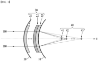
- FIG. 1 illustrates the overall structure of a contact lens made of multilayer wave plates according to an embodiment of the present invention
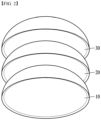
- FIGS. 2 and 3 illustrate the structure of the structure of the contact lens made of multilayer wave plates according to an embodiment of the present invention.
- the contact lens made of multilayer wave plates includes a corneal protective layer 10, a wave plate layer 20 and a lens surface layer 30.
- the corneal protective layer 10 is in direct contact with the eyeball when worn. Accordingly, the corneal protective layer 10 has a convex shape with approximately constant curvature depending on the shape of the eyeball.
- the size or thickness of the corneal protective layer 10 may be set in various ways depending on the designer's intention.
- the lens surface layer 30 is exposed to the outside when worn on the eyeball.
- the lens surface layer 30 is formed to have a certain thickness to determine the power of the eye.
- the lens surface layer 30 has a convex shape with approximately constant curvature, and is preferably formed with a smooth surface for natural contact with the eyelid when worn.
- the wave plate layer 20 includes a stack of two or more wave plates 21, 22 and 23, and is placed between the corneal protective layer 10 and the lens surface layer 30.
- the wave plate layer 20 may be composed of a total of m (m ⁇ 2) wave plates from the first wave plate 21 to the last wave plate 23.
- FIG. 1 shows a stack of three or more wave plates, but as described above, two or more wave plates are stacked.
- the wave plates 21, 22 and 23 are optical elements that change the polarization state of light, and are lenses (waveplate lens: WL) made of birefringent material.
- a wave plate 200 is also called a phase retardation plate.
- a phase retardation plate a polarization direction in which the speed of light is fast is called a fast axis, and a polarization direction having an axis perpendicular to the fast axis and a slow light speed is called a slow axis.
- the phase retardation plate includes a Half Wave Plate (HWP) which retards the phase of ⁇ /2; and a Quarter Wave Plate (QWP) which retards the phase of ⁇ /4.
- HWP Half Wave Plate
- QWP Quarter Wave Plate
- a linearly polarized beam passes at an angle of ⁇ with the fast axis of the HWP, it is rotated and polarized by 2 ⁇ , and when the linearly polarized beam passes at an angle of 45 degrees with the fast axis of the QWP, a circularly polarized beam is produced.
- the polarization conversion technology of linearly polarized or circularly polarized beams that have passed through the HWP and the QWP is a known technology, so a detailed description thereof is omitted in this specification.
- FIG. 4 illustrates the cross section of an existing diffractive lens.
- Equation 2 F m
- Equation 2 F m
- the wave plates 21, 22 and 23 according to the present invention are formed in an annular shape, and are manufactured to have a constant thickness depending on the distance from the center of the wave plates 21, 22 and 23 to perform the function of a Fresnel lens.
- incident light has a left-handed circular polarization (LHCP) or a right-handed circular polarization (RHCP)
- LHCP left-handed circular polarization
- RHCP right-handed circular polarization
- a phase distribution with multi-focal points similar to Equations 1 and 2 may be formed by adjusting the arrangement direction of the fast axis and slow axis of the wave plate according to the present invention.
- the wave plates 21, 22 and 23 are transparent materials and may be composed of an anisotropic material such as liquid crystal or, more generally, reactive mesogen.
- the thickness of the wave plates 21, 22 and 23 may be smaller than the wavelength of the incident light 100, equal to the wavelength of the incident light 100, or thicker than the wavelength of the incident light 100.
- the wave plates 21, 22 and 23 are manufactured by forming a pattern for controlling optical axis rotation at their local positions.
- an odd-numbered wave plate e.g., the first wave plate 21
- an even-numbered wave plate e.g., the second wave plate 22
- the multi-focal points 40 are formed. As shown in FIG. 1 , the multi-focal points 40 may be composed of a total of n focal points from the first focal point 41 to the last focal point 43. The number of focal points formed according to an embodiment of the present invention is described below.
- FIG. 5 illustrates the phase distribution of wave plates according to an embodiment of the present invention.
- the phase difference distribution shown in FIG. 5 is within the wavelength range of incident light and has a sawtooth cross-section.
- the graph of FIG. 5(a) illustrates the phase distribution shown in the odd-numbered wave plate
- the graph of FIG. 5(b) illustrates the phase distribution shown in the even-numbered wave plate.
- a point where the phase suddenly changes appears as the radius increases.
- points, where the phase suddenly changes, in the phase distribution of the odd-numbered wave plate are indicated as P1 to Pn
- points, where the phase changes suddenly, in the phase distribution of the even-numbered wave plate are indicated as P1' to Pn'.
- the phase position Pn corresponds to the position of r j in Equation 1.
- a section from X1 to the subsequent phase section and a section from X1' to the subsequent phase section are collectively referred to as the X section.
- phase in the even-numbered wave plate decreases while the phase in the odd-numbered wave plate increases. That is, the phase sign (+ ⁇ ) of the odd-numbered wave plate and the phase sign (- ⁇ ) of the even-numbered wave plate should be opposite to each other.
- this relation is called a complementary relation.
- the values (absolute values) of phase magnitudes may be the same or different.
- the positions at which the focal points are formed may be adjusted. Specifically, referring to FIG. 5 and Equation 1, when one of the wave plates 21, 22 and 23 is manufactured, a phase value in a range of - ⁇ ⁇ + ⁇ and a phase position (Pn or r j ) are determined.
- the phase position (Pn or r j ) is changed, and the focal length (F in Equation 1) is also changed. For example, as the spacing of the X section decreases, the focal length also decreases.
- the phase in the odd-numbered lens wave plate may decrease, and the phase in the even-numbered lens wave plate may increase.
- the wave plate layer 20 may have a convex shape with a certain curvature such that it is naturally disposed on the corneal protective layer 10 and the lens surface layer 30.
- the total number of layers of the wave plates, the curvature of the surface of the corneal protective layer 10 and lens surface layer 30, the birefringent refractive index distribution of each of the wave plates, and the like may be varied to achieve the refractive correction needed for distance and near vision with other lenses in a user's visual system.
- the case where one wave plate is arranged and the case where wave plates whose phase distributions are not complementary to each other are arranged next to each other are compared with the contact lens made of multilayer wave plates according to the present invention.
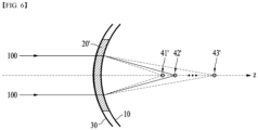
- FIG. 6 illustrates a state in which one wave plate is disposed on a contact lens
- FIG. 7 illustrates focal point positions and light intensity distribution according to changes in the thickness of the wave plate of FIG. 6 .
- FIGS. 6 and 7 when only one wave plate 20' is disposed between the corneal protective layer 10 and the lens surface layer 30 and linearly polarized light 100 is incident, three focal points 41', 42' and 43' are formed. As shown in FIG. 7 , when the thickness (h) of the wave plate is ⁇ /2, ⁇ /3 and ⁇ /4, light intensity appears at each focal point. As such, in the case of the contact lens where only one wave plate 20' is disposed, the total number of focal points is limited to a maximum of three. Meanwhile, it can be seen that the light intensity at each focal point position changes when the thickness (h) of the wave plate changes.
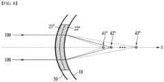
- FIG. 8 illustrates a contact lens in which two non-complementary wave plates are stacked and arranged
- FIG. 9 illustrates focal point positions and light intensity distribution when the thickness of each of the wave plates of FIG. 8 is ⁇ /4.
- a first wave plate 21" and second wave plate 22" are stacked and arranged between a corneal protective layer 10 and a lens surface layer 30.
- the first wave plate 21" and the second wave plate 22" are arranged adjacent to each other, but the phase distributions of the wave plates 21" and 22" are not complementary to each other.
- the thickness of each of the wave plates is ⁇ /4
- the total thickness is ⁇ /2. This is a case where the thickness of the wave plate is ⁇ /2, and the total number of focal points is limited to a maximum of three (see FIG. 7(a) ).
- Equation 3 may be applied also when one wave plate is disposed in a contact lens.
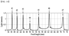
- FIG. 10 illustrates multiple focal points formed when two wave plates whose phases are complementary to each other are stacked and arranged in the contact lens according to an embodiment of the present invention
- FIG. 11 illustrates light intensity changes at each focal point position which is dependent upon changes in the thickness of the wave plate layer in the contact lens according to an embodiment of the present invention.
- two wave plates 21 and 22 are stacked and arranged in a contact lens.
- the first wave plate 21 and the second wave plate 22 are arranged adjacent to each other, and the phase distributions of the wave plates 21 and 22 are complementary to each other.
- the thickness of each of the wave plates is ⁇ /4, the total thickness is ⁇ /2.
- the maximum number of focal points formed by these multifocal lenses is seven.
- the magnitudes of phases may be different when the first wave plate 21 and the second wave plate 22 are in a complementary relation.
- the value of light intensity may be changed without changing the number of focal points.
- N 4 ⁇ 2 m ⁇ 1 ⁇ 1
- N the maximum number of focal points
- m the number of wave plates.
- RHCP and LHCP are present in the same ratio.
- the direction of circularly polarized light included in the incident light changes.
- RHCP included in linearly polarized light changes into LHCP. That is, as linearly polarized light passes through the wave plate, it experiences geometric phase delay as the LHCP and RHCP have opposite signs.
- the remaining light that is not converted while passing through the wave plate is not affected by geometric phase delay and passes through the wave plate as linearly polarized light.
- Equation 5 shows the efficiency (referred to as polarization conversion efficiency) of passing through the wave plate without being polarized, and the light intensity at the location where each focal point is formed is affected by the polarization conversion efficiency.
- FIGS. 6 and 7 are referred to again.
- the number of focal points is three (F-1, F-2 and F-3) according to Equation 3 (or Equation 4).
- the wave plate 20' has a thickness where a half-wavelength phase delay occurs, linearly polarized light is not generated, so the number of focal points is two (see FIG. 7(a) ).
- the focal length ( f WL- 1 ) of the wave plate when incident light is circularly polarized light and passes through the wave plate, the sign changes while experiencing phase delay, as described above. Accordingly, when a focal length by RHCP is + f WL -1 , a focal length by LHCP is - f WL -1 .
- LHCP and RHCP pass through the wave plate, they are converted into circularly polarized light with opposite signs, so the wave plate functions like a convex lens for one circularly polarized light and like a concave lens for the other circularly polarized light. Meanwhile, if incident light is linearly polarized light, the focal length is infinite.
- Equation 6 is a formula for calculating three focal lengths by one wave plate.
- each focal length formed by the wave plates can be calculated by repeating Equation 6 as many times as the number of wave plates. Specifically, if the number of wave plates increases by one in the state of FIG. 6 , each focal length can be obtained by adding 1 f WL ⁇ 2 to the right side of Equation 6.
- the increased number of focal points can be obtained by Equation 4.
- the number of focal points can be changed by adjusting the thickness of the wave plates, and the positions of focal points can be changed by adjusting the phase distribution of each of the wave plates (see Equations 1 and 7).
- the adjusted focal points may be divided into a near focal point, a middle focal point and a far focal point depending on setting. Accordingly, various focal points may be formed depending on the visual condition of a contact lens user and the purpose of use according to the present invention.
- the wave plate layer 20 according to the present invention when placed in a contact lens, the light intensity distribution of multiple focal points is created spatially along the diametric distance of the contact lens as moving away from the last wave plate in the Z-axis direction when incident light passes through the contact lens. That is, focal points formed through the contact lens according to the present invention may be created spatially as well as in the Z-axis direction.
- FIGS. 13A to 13F illustrate various embodiments in which the wave plate layers of the present invention are placed in a contact lens.
- the wave plate layers 20 satisfying a complementary relation are disposed between the corneal protective layer 10 and the lens surface layer 30.
- the wave plate layers 20 may be disposed on the corneal protective layer 10 in an appropriate form considering various conditions such as the surrounding environment (e.g., indoors or outdoors, etc.) of a contact lens wearer, a user's eye condition (e.g., hyperopia, myopia, etc.) and changes in pupil size.
- the corneal protective layer 10 may be divided into a central region, which is a central part, and a peripheral region, which is a peripheral part.
- the area of the central region may be set in various ways depending on a designer's intention.
- the wave plate layers 20 may have various shapes (e.g., a circular, oval, polygonal or annular shape, etc.), the number of the wave plate layers 20 may be various, and the wave plate layers may be disposed in the central region or peripheral region.
- the wave plate layer 20 is basically disposed in the central region of the corneal protective layer 10. This embodiment may be suitable when a contact lens wearer is outdoors.
- the wave plate layer 20 is formed in a substantially circular shape and is disposed only in the central region of the corneal protective layer 10.
- the area of the wave plate layer 20 is smaller than the area of the corneal protective layer 10.
- one wave plate layer 20 is placed in the central region, and another wave plate layer 20 is formed in an annular shape with a certain thickness to surround the central region and formed in a peripheral region spaced a certain distance in the radial direction from the central region.
- one wave plate layer 20 is disposed in the central region, and two wave plate layers 20 with different radii are formed in an annular shape with a certain thickness to surround the central region and formed in a peripheral region spaced a certain distance in the radial direction from the central region.
- the wave plate layer 20 is basically disposed in the peripheral region excluding the central region of the corneal protective layer 10. This embodiment may be suitable when a contact lens wearer is indoors.
- the wave plate layer 20 is formed an annular shape with a certain thickness to surround the periphery of the corneal protective layer 10 and disposed in a peripheral region of the corneal protective layer 10.
- one wave plate layer 20 is formed in an annular shape having a size smaller than the corneal protective layer 10 and having a certain thickness and disposed in a peripheral region excluding the central region of the corneal protective layer 10.
- one wave plate layer 20 is formed in an annular shape with a certain thickness and disposed in a first peripheral region excluding the central region, and another wave plate layer 20 is formed in an annular shape with a certain thickness and disposed in a second peripheral region spaced a certain distance away from the first peripheral region while surrounding the first peripheral region.
- the wave plate layer 20 disposed in the central region may have various shapes such as a circular, oval, or polygonal shape, as described above.
- the wave plate layer 20 disposed in the peripheral region may have a semi-ring shape spaced a certain distance apart in the outer direction of the central region, a shape arranged at regular intervals in the circumferential direction with the same radius, or the like.
- the total number of wave plates, the curvature of the refractive lens surface, the distribution of the refractive index of each of the wave plates, and the like in the present invention may be varied to achieve the refractive compensation required for distance and near vision with other lenses in a visual system.
- the wave plate layer 20 may be disposed in the entire or partial region of the corneal protective layer 10.
Landscapes
- Physics & Mathematics (AREA)
- Health & Medical Sciences (AREA)
- Ophthalmology & Optometry (AREA)
- General Physics & Mathematics (AREA)
- Optics & Photonics (AREA)
- General Health & Medical Sciences (AREA)
- Eyeglasses (AREA)
Abstract
Description
- The present invention relates to a contact lens made of multilayer wave plates, and more particularly to a contact lens made of multilayer wave plates, the contact lens including two or more wave plates disposed between a corneal protective layer and lens surface layer of a contact lens to increase the number of focal points
- Common conditions that cause poor vision include myopia and hyperopia. These conditions are usually due to an imbalance between the length of the eye and the focal point of the eye's optical elements. In myopic eyes, the focal points are set in front of the retinal plane, and in hyperopic eyes, the focal points are set in the back of the retinal plane. Myopia typically occurs because the axial length of the eye grows longer than the focal length of the eye's optical components, meaning the eye grows too long. Hyperopia typically occurs because the axial length of the eye is too short compared to the focal length of the eye's optical components, meaning the eye does not grow long enough.
- The ability to adjust focal length, i.e., to focus on near and distant objects without relying on changes in focal length, can be improved by using intraocular multifocal lenses or contact lenses. Multifocal lenses have different focal lengths for near and far vision.
- Among the techniques for manufacturing multifocal diffractive lenses, a method involving a diffractive wave plate element made of a birefringent material is known. This method has the advantage of a relatively easy manufacturing process and low cost.
- As a related art regarding multifocal lenses having a diffractive wave plate element, there is US Patent No.
US 9,753,193 - However, in
US Patent No. 9,753,193 - Therefore, the present invention has been made in view of the above problems, and it is one object of the present invention to provide a contact lens made of multilayer wave plates that are stacked to have complementary phases to each other in the contact lens, thereby being capable of increasing the number of focal points compared to an existing contact lens.
- In accordance with an aspect of the present invention, the above and other objects can be accomplished by the provision of a contact lens made of multilayer wave plates, the contact lens including: a lens surface layer; a corneal protective layer; and a wave plate layer in which two or more wave plates composed of a birefringent material are stacked and which is disposed between the lens surface layer and the corneal protective layer, and phases of neighboring wave plates in the wave plate layer have opposite phase signs so as to complement each other.
- In an embodiment of the present invention, when a thickness of one or more wave plates in the wave plate layer changes, light intensity at a position where focal points are formed may change accordingly.
- In an embodiment of the present invention, a thickness of the wave plate layer changes such that a light intensity at a position where one focal point is formed becomes 0, the number of focal points may change.
- In an embodiment of the present invention, the number of focal points generated by the wave plate layer may be calculated by
Equation 1 below:
- In an embodiment of the present invention, positions of focal points generated by the wave plate layer may be calculated as shown in
Equation 2 below according to the number of the wave plates:
- In an embodiment of the present invention, , when a phase section (X) between a center of the wave plate layer and a point where a phase changes suddenly changes, positions where focal points are formed may change accordingly.
- In an embodiment of the present invention, in a same phase section (X) between neighboring first and second wave plates in the wave plate layer, a phase in the second wave plate may decrease as a phase in the first wave plate increases.
- In an embodiment of the present invention, the wave plate layer may be disposed in a central region of the corneal protective layer.
- In an embodiment of the present invention, the wave plate layer disposed in the central region may have a smaller area than the corneal protective layer.
- In an embodiment of the present invention, among the wave plate layer, one wave plate layer may be disposed in a central region of the corneal protective layer, and another wave plate layer may be disposed in a peripheral region excluding the central region at a certain distance spaced from the central region in a direction outside the central region.
- In an embodiment of the present invention, the wave plate layer disposed in the peripheral region may be formed in an annular shape with a certain thickness.
- In an embodiment of the present invention, a plurality of wave plate layers may be formed in an annular shape with a certain thickness in the peripheral region, may have different radii, and may be arranged at a certain distance away from an adjacent wave plate layer.
- In an embodiment of the present invention, the wave plate layer may be disposed in a peripheral region excluding a central region of the corneal protective layer.
- In an embodiment of the present invention, the wave plate layer may be formed to surround a periphery of the corneal protective layer.
- In an embodiment of the present invention, the wave plate layer may be formed inside the corneal protective layer.
- In an embodiment of the present invention, the wave plate layer may be formed in an annular shape with a certain thickness.
- In an embodiment of the present invention, among the wave plate layer, one wave plate layer may be disposed in a first peripheral region excluding a central region of the corneal protective layer, and another wave plate layer may be disposed in a second peripheral region spaced a certain distance away from the first peripheral region in an outer direction of the first peripheral region.
- In an embodiment of the present invention, a plurality of wave plate layers may be formed in an annular shape with a certain thickness in the second peripheral region, may have different radii and may be arranged at a certain distance away from an adjacent wave plate layer.
- According to the present invention, the number of focal points can increase in proportion to the number of wave plates. By using this, a contact lens with multi-focal points can be easily manufactured.
- In addition, the present invention can be applied not only to vision correction but also to industrial fields that require multifocal lenses such as microscopes and cameras.
- In addition, in the present invention, the total number of wave plates, the curvature of a lens surface layer and the refractive index distribution of each wave plate can be varied to achieve the refractive compensation required for distance and near vision with other lenses in the visual system.
- Further, the degree of light intensity at positions where focal points are formed can be changed by changing the thickness of the wave plates, and the number of focal points can be adjusted within the maximum number of focal points.
-
-
FIG. 1 illustrates the overall structure of a contact lens made of multilayer wave plates according to an embodiment of the present invention. -
FIGS. 2 and3 illustrate the structure of the structure of the contact lens made of multilayer wave plates according to an embodiment of the present invention. -
FIG. 4 illustrates the cross section of an existing diffractive lens. -
FIG. 5 illustrates the phase distribution of wave plates according to an embodiment of the present invention. -
FIG. 6 illustrates a state in which one wave plate is disposed on a contact lens. -
FIG. 7 illustrates focal point positions and light intensity distribution according to changes in the thickness of the wave plate ofFIG. 6 . -
FIG. 8 illustrates a contact lens in which two non-complementary wave plates are stacked and arranged. -
FIG. 9 illustrates focal point positions and light intensity distribution when the thickness of each of the wave plates ofFIG. 8 is λ/4. -
FIG. 10 illustrates multiple focal points formed when two wave plates whose phases are complementary to each other are stacked and arranged in the contact lens according to an embodiment of the present invention. -
FIG. 11 illustrates light intensity changes at each focal point position which is dependent upon changes in the thickness of the wave plate layer in the contact lens according to an embodiment of the present invention. -
FIG. 12 illustrates the number of focal points formed after incident light passes through a wave plate layer according to an embodiment of the present invention. -
FIGS. 13A to 13F illustrate various embodiments in which the wave plate layers of the present invention are placed in a contact lens. - Hereinafter, a contact lens made of multilayer wave plates according to a preferred embodiment will be described in detail with reference to the attached drawings. Here, the same symbols are used for the same components, and repetitive descriptions and detailed descriptions of known functions and configurations that may unnecessarily obscure the gist of the invention are omitted. Embodiments of the invention are provided to more completely explain the present invention to those with average knowledge in the art. Therefore, the shapes and sizes of elements in the drawings may be exaggerated for clearer explanation.
-
FIG. 1 illustrates the overall structure of a contact lens made of multilayer wave plates according to an embodiment of the present invention, andFIGS. 2 and3 illustrate the structure of the structure of the contact lens made of multilayer wave plates according to an embodiment of the present invention. - Referring to
FIGS. 1 to 3 , the contact lens made of multilayer wave plates according to an embodiment of the present invention includes a cornealprotective layer 10, awave plate layer 20 and alens surface layer 30. - The corneal
protective layer 10 is in direct contact with the eyeball when worn. Accordingly, the cornealprotective layer 10 has a convex shape with approximately constant curvature depending on the shape of the eyeball. The size or thickness of the cornealprotective layer 10 may be set in various ways depending on the designer's intention. - The
lens surface layer 30 is exposed to the outside when worn on the eyeball. Thelens surface layer 30 is formed to have a certain thickness to determine the power of the eye. Thelens surface layer 30 has a convex shape with approximately constant curvature, and is preferably formed with a smooth surface for natural contact with the eyelid when worn. - The
wave plate layer 20 includes a stack of two ormore wave plates protective layer 10 and thelens surface layer 30. Thewave plate layer 20 may be composed of a total of m (m≥2) wave plates from thefirst wave plate 21 to thelast wave plate 23.FIG. 1 shows a stack of three or more wave plates, but as described above, two or more wave plates are stacked. - The
wave plates wave plate 200 is also called a phase retardation plate. In a phase retardation plate, a polarization direction in which the speed of light is fast is called a fast axis, and a polarization direction having an axis perpendicular to the fast axis and a slow light speed is called a slow axis. The phase retardation plate includes a Half Wave Plate (HWP) which retards the phase of λ/2; and a Quarter Wave Plate (QWP) which retards the phase of λ/4. For example, when a linearly polarized beam passes at an angle of θ with the fast axis of the HWP, it is rotated and polarized by 2θ, and when the linearly polarized beam passes at an angle of 45 degrees with the fast axis of the QWP, a circularly polarized beam is produced. The polarization conversion technology of linearly polarized or circularly polarized beams that have passed through the HWP and the QWP is a known technology, so a detailed description thereof is omitted in this specification. -
FIG. 4 illustrates the cross section of an existing diffractive lens. - Meanwhile, in the case of a diffractive lens commonly known as the Fresnel lens, the diffractive lens has a sawtooth shape as the radius from the center of the diffraction lens increases, as shown in
FIG. 4 , and it has a phase distribution as shown inEquation 1 below depending on the size of the radius:
- In addition, as the phase distribution shown in
Equation 1 moves away from the diffraction lens, several focal points are formed as shown inEquation 2 below:
- Unlike the shape of the Fresnel lens described above, the
wave plates wave plates Equations - The
wave plates wave plates incident light 100, equal to the wavelength of theincident light 100, or thicker than the wavelength of theincident light 100. - Regarding a manufacturing method of the
wave plates wave plates wave plates - Meanwhile, in the
wave plate layer 20, an odd-numbered wave plate (e.g., the first wave plate 21) and an even-numbered wave plate (e.g., the second wave plate 22) are arranged adjacent to each other. When the incident light 100 passes through thelast wave plate 23 of the present invention,multi-focal points 40 are formed. As shown inFIG. 1 , themulti-focal points 40 may be composed of a total of n focal points from the firstfocal point 41 to the lastfocal point 43. The number of focal points formed according to an embodiment of the present invention is described below. -
FIG. 5 illustrates the phase distribution of wave plates according to an embodiment of the present invention. - Now, the phase distribution of the
wave plates FIG. 5 illustrates a phase distribution representing the phase difference of a light ray passing through a position separated by a radius r from the center of the optical axis (a point where r=0) in the transmitted wavefront incident on the wave plate. The phase difference distribution shown inFIG. 5 is within the wavelength range of incident light and has a sawtooth cross-section. - The graph of
FIG. 5(a) illustrates the phase distribution shown in the odd-numbered wave plate, and the graph ofFIG. 5(b) illustrates the phase distribution shown in the even-numbered wave plate. Examining the phase distribution, a point where the phase suddenly changes (changes from +π to -π or from -π to +π) appears as the radius increases. InFIG. 5 , points, where the phase suddenly changes, in the phase distribution of the odd-numbered wave plate are indicated as P1 to Pn, and points, where the phase changes suddenly, in the phase distribution of the even-numbered wave plate are indicated as P1' to Pn'. The phase position Pn corresponds to the position of rj inEquation 1. Here, the phase section from the center (r=0) to P1 is called the X1 section, and the phase section from the center (r=0) to P1' is called the X1' section. Although not illustrated inFIG. 3 , phase sections up to P2 and P2' based on the center (r=0) are called X2 and X2' sections, respectively, and the following phase sections may be displayed in the above-described manner. In this specification, a section from X1 to the subsequent phase section and a section from X1' to the subsequent phase section are collectively referred to as the X section. - Referring to the phase distribution according to an embodiment of the present invention of
FIG. 5 again, in the same phase section (X), the phase in the even-numbered wave plate decreases while the phase in the odd-numbered wave plate increases. That is, the phase sign (+ϕ) of the odd-numbered wave plate and the phase sign (-ϕ) of the even-numbered wave plate should be opposite to each other. In this specification, this relation is called a complementary relation. Here, the values (absolute values) of phase magnitudes may be the same or different. - Here, when the
wave plates FIG. 5 andEquation 1, when one of thewave plates wave plates - Meanwhile, according to another embodiment of the present invention, in the same phase section (X), the phase in the odd-numbered lens wave plate may decrease, and the phase in the even-numbered lens wave plate may increase.
- The
wave plate layer 20 may have a convex shape with a certain curvature such that it is naturally disposed on the cornealprotective layer 10 and thelens surface layer 30. - Meanwhile, the total number of layers of the wave plates, the curvature of the surface of the corneal
protective layer 10 andlens surface layer 30, the birefringent refractive index distribution of each of the wave plates, and the like may be varied to achieve the refractive correction needed for distance and near vision with other lenses in a user's visual system. - Hereinafter, to investigate the effects of the contact lens made of multilayer wave plates according to the present invention, the case where one wave plate is arranged and the case where wave plates whose phase distributions are not complementary to each other are arranged next to each other are compared with the contact lens made of multilayer wave plates according to the present invention.
-
FIG. 6 illustrates a state in which one wave plate is disposed on a contact lens, andFIG. 7 illustrates focal point positions and light intensity distribution according to changes in the thickness of the wave plate ofFIG. 6 . - Referring to
FIGS. 6 and7 , when only one wave plate 20' is disposed between the cornealprotective layer 10 and thelens surface layer 30 and linearlypolarized light 100 is incident, three focal points 41', 42' and 43' are formed. As shown inFIG. 7 , when the thickness (h) of the wave plate is λ/2, λ/3 and λ/4, light intensity appears at each focal point. As such, in the case of the contact lens where only one wave plate 20' is disposed, the total number of focal points is limited to a maximum of three. Meanwhile, it can be seen that the light intensity at each focal point position changes when the thickness (h) of the wave plate changes. -
FIG. 8 illustrates a contact lens in which two non-complementary wave plates are stacked and arranged, andFIG. 9 illustrates focal point positions and light intensity distribution when the thickness of each of the wave plates ofFIG. 8 is λ/4. - Referring to
FIGS. 8 and9 , afirst wave plate 21" andsecond wave plate 22" are stacked and arranged between a cornealprotective layer 10 and alens surface layer 30. Here, thefirst wave plate 21" and thesecond wave plate 22" are arranged adjacent to each other, but the phase distributions of thewave plates 21" and 22" are not complementary to each other. In addition, when the thickness of each of the wave plates is λ/4, the total thickness is λ/2. This is a case where the thickness of the wave plate is λ/2, and the total number of focal points is limited to a maximum of three (seeFIG. 7(a) ). - When the
multiple wave plates 21" and 22" that are not complementary to each other are arranged in a contact lens, the maximum number of focal points may be obtained as inEquation 3 below: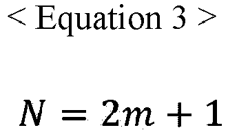
- In addition,
Equation 3 may be applied also when one wave plate is disposed in a contact lens. -
FIG. 10 illustrates multiple focal points formed when two wave plates whose phases are complementary to each other are stacked and arranged in the contact lens according to an embodiment of the present invention, andFIG. 11 illustrates light intensity changes at each focal point position which is dependent upon changes in the thickness of the wave plate layer in the contact lens according to an embodiment of the present invention. - Referring to
FIGS. 10 and11 , twowave plates first wave plate 21 and thesecond wave plate 22 are arranged adjacent to each other, and the phase distributions of thewave plates - When multiple wave plates in a complementary relation are arranged in the contact lens in such a manner, the maximum number of focal points increases.
- As described above, the magnitudes of phases may be different when the
first wave plate 21 and thesecond wave plate 22 are in a complementary relation. Here, when the magnitudes of the phases are different, the value of light intensity may be changed without changing the number of focal points. - The maximum number of focal points when multiple wave plates in a complementary relation are arranged in a contact lens may be obtained as shown in
Equation 4 below:
-
FIG. 11 illustrates a light intensity change at each focal point position which is dependent upon a change in the thickness of the wave plate layer in the contact lens according to an embodiment of the present invention. - The value calculated by
Equation 4 is the maximum number of focal points, and may adjust the number of focal points within the limit of the maximum number of the focal points by the thickness of the wave plate, i.e., by adjusting the light intensity at each focal point position. For example, when the thickness of at least one wave plate is adjusted to set the light intensity at at least one focal point position to 0 in the case where seven focal points are formed by the multifocal lenses of the present invention, the effect of disappearing the focal point at the position may be obtained, thereby reducing the total number of focal points. -
FIG. 11 illustrates a change in light intensity at each focal point position as the thickness (h) of the wave plate increases from 0 to λ when fivefocal points focal points focal points -
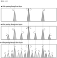
FIG. 12 illustrates the number of focal points formed after incident light passes through a wave plate layer according to an embodiment of the present invention. - As shown in
FIG. 12 , the number of focal points formed dependently upon the number of layers of the wave plate is a value calculated byEquation 4 above. - Meanwhile, a method for predicting the light intensity at a focal point position is as follows. Specifically, when RHCP or LHCP is incident on the
wave plate 200, the efficiency of converting it into polarized light in the opposite direction can be obtained as shown in Equation 5 below:

- In incident light that is linearly polarized light, RHCP and LHCP are present in the same ratio. When linearly polarized light is incident on a wave plate, the direction of circularly polarized light included in the incident light changes. For example, RHCP included in linearly polarized light changes into LHCP. That is, as linearly polarized light passes through the wave plate, it experiences geometric phase delay as the LHCP and RHCP have opposite signs. Here, the remaining light that is not converted while passing through the wave plate is not affected by geometric phase delay and passes through the wave plate as linearly polarized light. Equation 5 shows the efficiency (referred to as polarization conversion efficiency) of passing through the wave plate without being polarized, and the light intensity at the location where each focal point is formed is affected by the polarization conversion efficiency.
- Even when multiple wave plates are arranged, the light intensity at the location where each focal point is formed can be sufficiently predicted using Equation 5.
- Meanwhile, a method of determining a focal point position when the wave plate layer is disposed in the contact lens is as follows. For explanation,
FIGS. 6 and7 are referred to again. As shown inFIG. 6 , when there is one wave plate 20', the number of focal points is three (F-1, F-2 and F-3) according to Equation 3 (or Equation 4). Meanwhile, if the wave plate 20' has a thickness where a half-wavelength phase delay occurs, linearly polarized light is not generated, so the number of focal points is two (seeFIG. 7(a) ). - Each focal point position can be obtained as shown in
Equation 6 below:
- With regard to the focal length (f WL-1 ) of the wave plate, when incident light is circularly polarized light and passes through the wave plate, the sign changes while experiencing phase delay, as described above. Accordingly, when a focal length by RHCP is +f WL-1 , a focal length by LHCP is - f WL-1 . When LHCP and RHCP pass through the wave plate, they are converted into circularly polarized light with opposite signs, so the wave plate functions like a convex lens for one circularly polarized light and like a concave lens for the other circularly polarized light. Meanwhile, if incident light is linearly polarized light, the focal length is infinite.
-
Equation 6 is a formula for calculating three focal lengths by one wave plate. However, when multiple wave plates are arranged, each focal length formed by the wave plates can be calculated by repeatingEquation 6 as many times as the number of wave plates. Specifically, if the number of wave plates increases by one in the state ofFIG. 6 , each focal length can be obtained by adding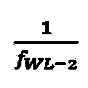
Equation 6. Here, the increased number of focal points can be obtained byEquation 4. This can be generalized as inEquation 7 below:
- In summary, when a phase distribution between neighboring wave plates of the contact lens made of multilayer wave plates according to the present invention satisfies a complementary relation, the number of focal points can be changed by adjusting the thickness of the wave plates, and the positions of focal points can be changed by adjusting the phase distribution of each of the wave plates (see
Equations 1 and 7). Here, the adjusted focal points may be divided into a near focal point, a middle focal point and a far focal point depending on setting. Accordingly, various focal points may be formed depending on the visual condition of a contact lens user and the purpose of use according to the present invention. - Meanwhile, when the
wave plate layer 20 according to the present invention is placed in a contact lens, the light intensity distribution of multiple focal points is created spatially along the diametric distance of the contact lens as moving away from the last wave plate in the Z-axis direction when incident light passes through the contact lens. That is, focal points formed through the contact lens according to the present invention may be created spatially as well as in the Z-axis direction. -
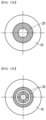
FIGS. 13A to 13F illustrate various embodiments in which the wave plate layers of the present invention are placed in a contact lens. - In the contact lens made of multilayer wave plates according to the present invention, the wave plate layers 20 satisfying a complementary relation are disposed between the corneal
protective layer 10 and thelens surface layer 30. Here, the wave plate layers 20 may be disposed on the cornealprotective layer 10 in an appropriate form considering various conditions such as the surrounding environment (e.g., indoors or outdoors, etc.) of a contact lens wearer, a user's eye condition (e.g., hyperopia, myopia, etc.) and changes in pupil size. - Meanwhile, the corneal
protective layer 10 may be divided into a central region, which is a central part, and a peripheral region, which is a peripheral part. Here, the area of the central region may be set in various ways depending on a designer's intention. The wave plate layers 20 may have various shapes (e.g., a circular, oval, polygonal or annular shape, etc.), the number of the wave plate layers 20 may be various, and the wave plate layers may be disposed in the central region or peripheral region. - In embodiments shown in
FIGS. 13A to 13C , thewave plate layer 20 is basically disposed in the central region of the cornealprotective layer 10. This embodiment may be suitable when a contact lens wearer is outdoors. - In the embodiment shown in
FIG. 13A , thewave plate layer 20 is formed in a substantially circular shape and is disposed only in the central region of the cornealprotective layer 10. Here, the area of thewave plate layer 20 is smaller than the area of the cornealprotective layer 10. - In the embodiment shown in
FIG. 13B , onewave plate layer 20 is placed in the central region, and anotherwave plate layer 20 is formed in an annular shape with a certain thickness to surround the central region and formed in a peripheral region spaced a certain distance in the radial direction from the central region. - In the embodiment shown in
FIG. 13C , onewave plate layer 20 is disposed in the central region, and two wave plate layers 20 with different radii are formed in an annular shape with a certain thickness to surround the central region and formed in a peripheral region spaced a certain distance in the radial direction from the central region. - In the embodiments shown in
FIGS. 13D to 13F , thewave plate layer 20 is basically disposed in the peripheral region excluding the central region of the cornealprotective layer 10. This embodiment may be suitable when a contact lens wearer is indoors. - In the embodiment shown in
FIG. 13D , thewave plate layer 20 is formed an annular shape with a certain thickness to surround the periphery of the cornealprotective layer 10 and disposed in a peripheral region of the cornealprotective layer 10. - In the embodiment shown in
FIG. 13E , onewave plate layer 20 is formed in an annular shape having a size smaller than the cornealprotective layer 10 and having a certain thickness and disposed in a peripheral region excluding the central region of the cornealprotective layer 10. - In the embodiment shown in
FIG. 13F , onewave plate layer 20 is formed in an annular shape with a certain thickness and disposed in a first peripheral region excluding the central region, and anotherwave plate layer 20 is formed in an annular shape with a certain thickness and disposed in a second peripheral region spaced a certain distance away from the first peripheral region while surrounding the first peripheral region. - However, the present invention is not limited to the embodiments shown in
FIGS. 13A to 13F . Thewave plate layer 20 disposed in the central region may have various shapes such as a circular, oval, or polygonal shape, as described above. In addition, thewave plate layer 20 disposed in the peripheral region may have a semi-ring shape spaced a certain distance apart in the outer direction of the central region, a shape arranged at regular intervals in the circumferential direction with the same radius, or the like. - Meanwhile, the total number of wave plates, the curvature of the refractive lens surface, the distribution of the refractive index of each of the wave plates, and the like in the present invention may be varied to achieve the refractive compensation required for distance and near vision with other lenses in a visual system. In addition, the
wave plate layer 20 may be disposed in the entire or partial region of the cornealprotective layer 10. - The present invention has been described with reference to an embodiment shown in the attached drawings, but this is merely illustrative, and those skilled in the art will recognize that various modifications and other equivalent embodiments are possible therefrom. Therefore, the true scope of protection of the present invention should be determined only by the appended claims.
Claims (18)
- A contact lens made of multilayer wave plates, the contact lens comprising:a lens surface layer;a corneal protective layer; anda wave plate layer in which two or more wave plates composed of a birefringent material are stacked and which is disposed between the lens surface layer and the corneal protective layer, andphases of neighboring wave plates in the wave plate layer have opposite phase signs so as to complement each other.
- The contact lens according to claim 1, wherein, when a thickness of one or more wave plates in the wave plate layer changes, light intensity at a position where focal points are formed changes accordingly.
- The contact lens according to claim 2, wherein, when a thickness of the wave plate layer changes such that a light intensity at a position where one focal point is formed becomes 0, the number of focal points changes.
- The contact lens according to claim 1, wherein the number of focal points generated by the wave plate layer is calculated by Equation 1 below:

- The contact lens according to claim 1, wherein positions of focal points generated by the wave plate layer is calculated as shown in Equation 2 below according to the number of the wave plates:

- The contact lens according to claim 1, wherein, when a phase section (X) between a center of the wave plate layer and a point where a phase changes suddenly changes, positions where focal points are formed change accordingly.
- The contact lens according to claim 1, wherein, in a same phase section (X) between neighboring first and second wave plates in the wave plate layer, a phase in the second wave plate decreases as a phase in the first wave plate increases.
- The contact lens according to claim 1, wherein the wave plate layer is disposed in a central region of the corneal protective layer.
- The contact lens according to claim 8, wherein the wave plate layer disposed in the central region has a smaller area than the corneal protective layer.
- The contact lens according to claim 1, wherein, among the wave plate layer, one wave plate layer is disposed in a central region of the corneal protective layer, and another wave plate layer is disposed in a peripheral region excluding the central region at a certain distance spaced from the central region in a direction outside the central region.
- The contact lens according to claim 10, wherein the wave plate layer disposed in the peripheral region is formed in an annular shape with a certain thickness.
- The contact lens according to claim 10, wherein a plurality of wave plate layers are formed in an annular shape with a certain thickness in the peripheral region, have different radii, and are arranged at a certain distance away from an adjacent wave plate layer.
- The contact lens according to claim 1, wherein the wave plate layer is disposed in a peripheral region excluding a central region of the corneal protective layer.
- The contact lens according to claim 13, wherein the wave plate layer is formed to surround a periphery of the corneal protective layer.
- The contact lens according to claim 13, wherein the wave plate layer is formed inside the corneal protective layer.
- The contact lens according to claim 13, wherein the wave plate layer is formed in an annular shape with a certain thickness.
- The contact lens according to claim 1, wherein, among the wave plate layer, one wave plate layer is disposed in a first peripheral region excluding a central region of the corneal protective layer, and another wave plate layer is disposed in a second peripheral region spaced a certain distance away from the first peripheral region in an outer direction of the first peripheral region.
- The contact lens according to claim 17, wherein a plurality of wave plate layers are formed in an annular shape with a certain thickness in the second peripheral region, have different radii, and are arranged at a certain distance away from an adjacent wave plate layer.
Applications Claiming Priority (3)
| Application Number | Priority Date | Filing Date | Title |
|---|---|---|---|
| KR20210160450 | 2021-11-19 | ||
| KR1020220019133A KR102816982B1 (en) | 2021-11-19 | 2022-02-14 | Contact lenses having mutiple wave plate |
| PCT/KR2022/018056 WO2023090839A1 (en) | 2021-11-19 | 2022-11-16 | Contact lens having multi-layered wavelength plate |
Publications (2)
| Publication Number | Publication Date |
|---|---|
| EP4435498A1 true EP4435498A1 (en) | 2024-09-25 |
| EP4435498A4 EP4435498A4 (en) | 2025-11-12 |
Family
ID=86397524
Family Applications (1)
| Application Number | Title | Priority Date | Filing Date |
|---|---|---|---|
| EP22896044.9A Pending EP4435498A4 (en) | 2021-11-19 | 2022-11-16 | CONTACT LENS WITH MULTI-LAYER WAVELENGTH PLATE |
Country Status (3)
| Country | Link |
|---|---|
| US (1) | US20240310655A1 (en) |
| EP (1) | EP4435498A4 (en) |
| WO (1) | WO2023090839A1 (en) |
Family Cites Families (18)
| Publication number | Priority date | Publication date | Assignee | Title |
|---|---|---|---|---|
| US5017000A (en) * | 1986-05-14 | 1991-05-21 | Cohen Allen L | Multifocals using phase shifting |
| US5056908A (en) * | 1987-11-12 | 1991-10-15 | Cohen Allen L | Optic zone phase channels |
| US4881805A (en) * | 1987-11-12 | 1989-11-21 | Cohen Allen L | Progressive intensity phase bifocal |
| US4848894A (en) * | 1988-06-01 | 1989-07-18 | The United States Of America As Represented By The Secretary Of The Army | Contact lens with laser protection |
| CN1285929A (en) * | 1997-12-29 | 2001-02-28 | 诺瓦提斯公司 | Composite holographic multifocal lens |
| US7188949B2 (en) * | 2004-10-25 | 2007-03-13 | Advanced Medical Optics, Inc. | Ophthalmic lens with multiple phase plates |
| US8142016B2 (en) * | 2008-09-04 | 2012-03-27 | Innovega, Inc. | Method and apparatus for constructing a contact lens with optics |
| US8531783B2 (en) * | 2010-02-09 | 2013-09-10 | Xceed Imaging Ltd. | Imaging method and system for imaging with extended depth of focus |
| US10386653B2 (en) * | 2012-12-21 | 2019-08-20 | Johnson & Johnson Vision Care, Inc. | Variable optic ophthalmic device including liquid crystal elements |
| US9195072B2 (en) * | 2013-07-25 | 2015-11-24 | Johnson & Johnson Vision Care, Inc. | Contact lenses with embedded labels |
| US9541772B2 (en) * | 2013-09-17 | 2017-01-10 | Johnson & Johnson Vision Care, Inc. | Methods and apparatus for ophthalmic devices including cycloidally oriented liquid crystal layers |
| EP3132307A4 (en) * | 2014-04-16 | 2017-04-05 | Beam Engineering For Advanced Measurements Co. | Methods and apparatus for human vision correction using diffractive waveplate lenses |
| JP6412556B2 (en) * | 2014-08-08 | 2018-10-24 | 株式会社メニコン | Diffraction multifocal lens and method of manufacturing diffractive multifocal lens |
| US11327306B2 (en) * | 2018-03-15 | 2022-05-10 | Facebook Technologies, Llc | Angular performance of apochromatic pancharatnam berry phase components using a C-plate |
| US10712564B2 (en) * | 2018-07-13 | 2020-07-14 | Tectus Corporation | Advanced optical designs for eye-mounted imaging systems |
| WO2020179012A1 (en) * | 2019-03-06 | 2020-09-10 | 株式会社ニコン | Ophthalmological lens and ophthalmological lens manufacturing method |
| CN110897762A (en) * | 2019-11-26 | 2020-03-24 | 暨南大学 | Artificial crystal based on Dammann zone plate and manufacturing method |
| US11719958B2 (en) * | 2020-02-04 | 2023-08-08 | Valdemar Portney | Multi-chamber switchable optical element |
-
2022
- 2022-11-16 EP EP22896044.9A patent/EP4435498A4/en active Pending
- 2022-11-16 WO PCT/KR2022/018056 patent/WO2023090839A1/en not_active Ceased
-
2024
- 2024-05-20 US US18/669,065 patent/US20240310655A1/en active Pending
Also Published As
| Publication number | Publication date |
|---|---|
| US20240310655A1 (en) | 2024-09-19 |
| WO2023090839A1 (en) | 2023-05-25 |
| EP4435498A4 (en) | 2025-11-12 |
Similar Documents
| Publication | Publication Date | Title |
|---|---|---|
| JP7733776B2 (en) | Lens element | |
| AU2020299826B2 (en) | Optical system | |
| US20210116720A1 (en) | Lens element | |
| KR100207164B1 (en) | Multifocal multizone diffractive ophthalmic lenses | |
| JP7006605B2 (en) | How to use prism augmentation lens and prism augmentation lens | |
| US9690882B2 (en) | Lens having an extended range of focus and method of making the same | |
| EP3561578A1 (en) | Lens element | |
| JPH032718A (en) | Lens for correcting astigmatism | |
| JP2015530610A (en) | Method for providing a customizable ophthalmic lens to the wearer's eye and associated active vision system | |
| EP3092525A1 (en) | Method and apparatus for creation and electrical tuning of spatially non-uniform reflection of light | |
| KR102816982B1 (en) | Contact lenses having mutiple wave plate | |
| US20240310655A1 (en) | Contact lenses having multiple wave plate | |
| TW202321738A (en) | Flexible liquid crystal-containing lenses | |
| US20240184142A1 (en) | Multi-focusing lenses having mutiple wave plate | |
| US20240184143A1 (en) | Extended depth of focus lenses having multiple wave plate | |
| CN118265943A (en) | Contact lens composed of multi-level wave plates | |
| US20260003211A1 (en) | Multifocal lens | |
| RU2788434C9 (en) | Lens | |
| TW202215114A (en) | Lens element | |
| RU2788434C2 (en) | Lens | |
| Song | Geometric-phase intraocular lenses with multifocality | |
| WO2021078198A1 (en) | Ophthalmic lens | |
| HK40111503A (en) | A contact lens | |
| WO2025186016A1 (en) | Lens element with optimized microlenses for abnormal refraction control | |
| HK40108219A (en) | Flexible liquid crystal-containing lenses |
Legal Events
| Date | Code | Title | Description |
|---|---|---|---|
| STAA | Information on the status of an ep patent application or granted ep patent |
Free format text: STATUS: THE INTERNATIONAL PUBLICATION HAS BEEN MADE |
|
| PUAI | Public reference made under article 153(3) epc to a published international application that has entered the european phase |
Free format text: ORIGINAL CODE: 0009012 |
|
| STAA | Information on the status of an ep patent application or granted ep patent |
Free format text: STATUS: REQUEST FOR EXAMINATION WAS MADE |
|
| 17P | Request for examination filed |
Effective date: 20240613 |
|
| AK | Designated contracting states |
Kind code of ref document: A1 Designated state(s): AL AT BE BG CH CY CZ DE DK EE ES FI FR GB GR HR HU IE IS IT LI LT LU LV MC ME MK MT NL NO PL PT RO RS SE SI SK SM TR |
|
| DAV | Request for validation of the european patent (deleted) | ||
| DAX | Request for extension of the european patent (deleted) | ||
| A4 | Supplementary search report drawn up and despatched |
Effective date: 20251014 |
|
| RIC1 | Information provided on ipc code assigned before grant |
Ipc: G02C 7/04 20060101AFI20251008BHEP Ipc: G02C 7/06 20060101ALI20251008BHEP Ipc: G02C 7/08 20060101ALI20251008BHEP Ipc: G02B 5/30 20060101ALI20251008BHEP Ipc: G02C 7/12 20060101ALI20251008BHEP |