EP4435345A1 - Unmanned aerial vehicle propelled autonomous multiplane cleaning system - Google Patents
Unmanned aerial vehicle propelled autonomous multiplane cleaning system Download PDFInfo
- Publication number
- EP4435345A1 EP4435345A1 EP24163407.0A EP24163407A EP4435345A1 EP 4435345 A1 EP4435345 A1 EP 4435345A1 EP 24163407 A EP24163407 A EP 24163407A EP 4435345 A1 EP4435345 A1 EP 4435345A1
- Authority
- EP
- European Patent Office
- Prior art keywords
- uav
- upamcs
- mopping
- cleaning
- base frame
- Prior art date
- Legal status (The legal status is an assumption and is not a legal conclusion. Google has not performed a legal analysis and makes no representation as to the accuracy of the status listed.)
- Granted
Links
Images






Classifications
-
- F—MECHANICAL ENGINEERING; LIGHTING; HEATING; WEAPONS; BLASTING
- F24—HEATING; RANGES; VENTILATING
- F24S—SOLAR HEAT COLLECTORS; SOLAR HEAT SYSTEMS
- F24S40/00—Safety or protection arrangements of solar heat collectors; Preventing malfunction of solar heat collectors
- F24S40/20—Cleaning; Removing snow
-
- B—PERFORMING OPERATIONS; TRANSPORTING
- B64—AIRCRAFT; AVIATION; COSMONAUTICS
- B64F—GROUND OR AIRCRAFT-CARRIER-DECK INSTALLATIONS SPECIALLY ADAPTED FOR USE IN CONNECTION WITH AIRCRAFT; DESIGNING, MANUFACTURING, ASSEMBLING, CLEANING, MAINTAINING OR REPAIRING AIRCRAFT, NOT OTHERWISE PROVIDED FOR; HANDLING, TRANSPORTING, TESTING OR INSPECTING AIRCRAFT COMPONENTS, NOT OTHERWISE PROVIDED FOR
- B64F5/00—Designing, manufacturing, assembling, cleaning, maintaining or repairing aircraft, not otherwise provided for; Handling, transporting, testing or inspecting aircraft components, not otherwise provided for
- B64F5/30—Cleaning aircraft
-
- B—PERFORMING OPERATIONS; TRANSPORTING
- B08—CLEANING
- B08B—CLEANING IN GENERAL; PREVENTION OF FOULING IN GENERAL
- B08B1/00—Cleaning by methods involving the use of tools
- B08B1/10—Cleaning by methods involving the use of tools characterised by the type of cleaning tool
- B08B1/14—Wipes; Absorbent members, e.g. swabs or sponges
-
- B—PERFORMING OPERATIONS; TRANSPORTING
- B08—CLEANING
- B08B—CLEANING IN GENERAL; PREVENTION OF FOULING IN GENERAL
- B08B1/00—Cleaning by methods involving the use of tools
- B08B1/30—Cleaning by methods involving the use of tools by movement of cleaning members over a surface
-
- B—PERFORMING OPERATIONS; TRANSPORTING
- B08—CLEANING
- B08B—CLEANING IN GENERAL; PREVENTION OF FOULING IN GENERAL
- B08B1/00—Cleaning by methods involving the use of tools
- B08B1/30—Cleaning by methods involving the use of tools by movement of cleaning members over a surface
- B08B1/32—Cleaning by methods involving the use of tools by movement of cleaning members over a surface using rotary cleaning members
- B08B1/34—Cleaning by methods involving the use of tools by movement of cleaning members over a surface using rotary cleaning members rotating about an axis parallel to the surface
-
- B—PERFORMING OPERATIONS; TRANSPORTING
- B08—CLEANING
- B08B—CLEANING IN GENERAL; PREVENTION OF FOULING IN GENERAL
- B08B1/00—Cleaning by methods involving the use of tools
- B08B1/30—Cleaning by methods involving the use of tools by movement of cleaning members over a surface
- B08B1/32—Cleaning by methods involving the use of tools by movement of cleaning members over a surface using rotary cleaning members
- B08B1/36—Cleaning by methods involving the use of tools by movement of cleaning members over a surface using rotary cleaning members rotating about an axis orthogonal to the surface
-
- F—MECHANICAL ENGINEERING; LIGHTING; HEATING; WEAPONS; BLASTING
- F16—ENGINEERING ELEMENTS AND UNITS; GENERAL MEASURES FOR PRODUCING AND MAINTAINING EFFECTIVE FUNCTIONING OF MACHINES OR INSTALLATIONS; THERMAL INSULATION IN GENERAL
- F16H—GEARING
- F16H1/00—Toothed gearings for conveying rotary motion
- F16H1/28—Toothed gearings for conveying rotary motion with gears having orbital motion
- F16H1/46—Systems consisting of a plurality of gear trains each with orbital gears, i.e. systems having three or more central gears
-
- H—ELECTRICITY
- H02—GENERATION; CONVERSION OR DISTRIBUTION OF ELECTRIC POWER
- H02S—GENERATION OF ELECTRIC POWER BY CONVERSION OF INFRARED RADIATION, VISIBLE LIGHT OR ULTRAVIOLET LIGHT, e.g. USING PHOTOVOLTAIC [PV] MODULES
- H02S40/00—Components or accessories in combination with PV modules, not provided for in groups H02S10/00 - H02S30/00
- H02S40/10—Cleaning arrangements
-
- B—PERFORMING OPERATIONS; TRANSPORTING
- B08—CLEANING
- B08B—CLEANING IN GENERAL; PREVENTION OF FOULING IN GENERAL
- B08B1/00—Cleaning by methods involving the use of tools
- B08B1/10—Cleaning by methods involving the use of tools characterised by the type of cleaning tool
-
- B—PERFORMING OPERATIONS; TRANSPORTING
- B08—CLEANING
- B08B—CLEANING IN GENERAL; PREVENTION OF FOULING IN GENERAL
- B08B1/00—Cleaning by methods involving the use of tools
- B08B1/10—Cleaning by methods involving the use of tools characterised by the type of cleaning tool
- B08B1/12—Brushes
-
- B—PERFORMING OPERATIONS; TRANSPORTING
- B08—CLEANING
- B08B—CLEANING IN GENERAL; PREVENTION OF FOULING IN GENERAL
- B08B1/00—Cleaning by methods involving the use of tools
- B08B1/40—Cleaning tools with integrated means for dispensing fluids, e.g. water, steam or detergents
-
- B—PERFORMING OPERATIONS; TRANSPORTING
- B08—CLEANING
- B08B—CLEANING IN GENERAL; PREVENTION OF FOULING IN GENERAL
- B08B3/00—Cleaning by methods involving the use or presence of liquid or steam
- B08B3/02—Cleaning by the force of jets or sprays
Definitions
- Autonomous cleaning is in demand for solar panels with varying installation types including roof top solar paneling and floating solar panels spread over wide areas. Clean solar panels improve the efficiency of power generation. Similarly, developments in building and construction has led to high rise buildings, which mostly are covered with glass panes. Cleaning of these inclined glass panes is a regular task performed during building maintenance. Autonomous cleaning is one of the ideal options for cleaning of the above stated surfaces.
- Cleaning systems proposed in the art have technical construct limitations in the cleaning mechanisms used, which lead to a lower ratio of power consumed to area cleaned, directly affecting the cleaning efficiency.
- Embodiments of the present disclosure present technological improvements as solutions to one or more of the above-mentioned technical problems recognized by the inventors in conventional systems.
- a system also referred as Unmanned Aerial Vehicle (UAV) Propelled Autonomous Multiplane Cleaning System (UPAMCS)
- UAV Unmanned Aerial Vehicle
- UPAMCS Unmanned Aerial Multiplane Cleaning System
- the system comprises a UAV and Mopping Interface Mechanism (UAV-MIM) mounted on a base frame connecting to a UAV as a slung load; a driver wheel frame connected to a rear end of the base frame, a pair of driving wheels attached to a lower side of the driver wheel frame at the rear end, a worm and a worm wheel, wherein the worm wheel is attached to a driver wheel axle of the pair of driving wheels, which in turn drives the worm about a vertical axis, a driver pulley fixed at a top end of the worm, wherein one or more driven pulley belts transmit drive from the driver pulley to one or more driven pulleys connecting one or more mopping systems.
- UAV-MIM UAV and Mopping Interface Mechanism
- Each mopping system comprising: a set of drive arms driven by the driven pulley attached, an annular gear wheel fixed to the lower side of the base frame, a set of planet gear wheels, each planet gear wheel from the set of planet gear wheels connected to a drive arm among the set of drive arms, wherein the set of planet gear wheels are meshed between fixed internal teeth of the annular gear wheel and a sun gear wheel, while each of the drive arm rotates the set of planet gear wheels which in turn rotates the sun gear wheel and a mopping material fixed to a bottom side of the sun gear wheel and the set of planet gear wheels.
- the system further comprises a cleaning fluid distribution network attached to the base frame comprising (i) an inclined surface cleaning mechanism for spraying a cleaning fluid in upward direction and (ii) a flat surface cleaning mechanism for spraying the cleaning fluid in downward direction for a surface to be cleaned below the one or more mopping systems.
- a cleaning fluid distribution network attached to the base frame comprising (i) an inclined surface cleaning mechanism for spraying a cleaning fluid in upward direction and (ii) a flat surface cleaning mechanism for spraying the cleaning fluid in downward direction for a surface to be cleaned below the one or more mopping systems.
- Embodiments herein provide a system also referred to as an Unmanned Aerial Vehicle (UAV) Propelled Autonomous Multiplane Cleaning System (UPAMCS) for surface cleaning of flat and inclined surfaces.
- UAV-MIM Unmanned Aerial Vehicle
- An UAV and Mopping Interface Mechanism (UAV-MIM) connects a UAV to one or more mopping systems comprising an epicyclic gear system, also referred to as planetary gear system, driven moppers with no additional power devices used.
- a maneuvering mechanism disclosed enables the UAV to propel the mopping systems to reach any geometric shape or inclination.
- the UPAMCS provides cost, time, and power efficient surface cleaning.
- the UPAMCS is also equipped with vision cameras and Light Detection and Ranging (LiDAR) for guidance during landing and crawling over surfaces along with additional surface defect detection by performing image processing on the captured images.
- LiDAR Light Detection and Ranging
- FIG. 1A through FIG. 6 where similar reference characters denote corresponding features consistently throughout the figures, there are shown preferred embodiments and these embodiments are described in the context of the following exemplary system and/or method.
- Reference numerals of one or more components of the UPAMCS as depicted in the FIGS. 1A through 5B are provided in Table 1 below for ease of description: Table 1 Sl.
- Numeral reference 1 System UAV Propelled Autonomous Multiplane Cleaning System (UPAMCS) 100 2 UAV-MIM 102 3 Base frame (rear end, front end, Left Hand Side (LHS) and Right Hand Side (RHS) 104 4 UAV 106 5 UAV-MIM mounting 108A-D 6 Driving wheel frame 110 7 Pair of Driving wheels- Rear end 112 8 Driven wheels (front end, LHS, RHS) 114A-C 9 Worm 116A 10 Worm wheel 116B 11 Driver Pulley 118 12 Driven pulley belts 120A-B 13 Driven pulleys 122A-B 14 Mopping system 124A-B 15 Set of Drive arms 126A-B 16 Sun gear wheel 128A-B 17 Annular Gear wheel 130A-B 18 Set of planet gear wheels 132A-B 19 Mopping material 134 20 Cleaning Fluid Distribution Network 136 21 Vision cameras 138A-D 22 LiDARS 140A-D 23 Electrical nozzle actuation system 142A-B 24 Pro
- UPAMCS U
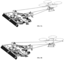
- FIG. 1A is a three dimensional (3-D) view of the system 100, also referred to the UPAMCS, in the first mode (UPAMCS 1) of operation comprising a single mopping system depicted in a lifting configuration, according to some embodiments of the present disclosure.
- FIG. 1B is a three dimensional (3-D) view of the system 100 (UPAMCS), in a second mode of operation (UPAMCS2) comprising a dual mopping system depicted in a lifting configuration, according to some embodiments of the present disclosure.
- the UAV and Mopping Interface Mechanism (UAV-MIM) 102 is mounted on the base frame 104 connecting to the UAV 106 as a slung load making the UPAMCS portable, which can be easily lifted and placed on surface to be cleaned.
- the UAV 106 for example a drone, functions as a primary driving system, wherein the UAV lifts the base frame 104 mounted with the mopping systems via the UAV-MIM 102 with the lifting configuration.
- the UAV 106 depicted in FIGS. 1A through FIG. 6 figure is only for illustration. As understood by person having ordinary skill in the art, an appropriate payload UAV can be selected in accordance with the end user requirements and constraints.
- the UAV-MIM 102 becomes vertical with the UAV 106 powered for lift off. Once the system 100 reaches the destination (surface to be cleaned), the system 100 lands gently and operating configuration is activated as depicted in FIG. 4A and 5A . It can be understood that lift off, landing, and setting the UAV-MIM 102 into operation mode of interest is controlled via the UAV maneuvering. Thus, once the system 100 lands, the UAV 106 automatically rotates the UAV-MIM 104 to align approximately at 5 degrees to the surface panel horizon. This mechanism enables maximum thrust of the UAV 106 to be used for driving the mopping system 124A-B. The system 100 can be steered by the steering mechanism placed at the drive wheel frame 110.
- the steering configuration is depicted in 4B and 4C.
- the UAV 106 propels forward the pair of driving wheels 112 (at rear end of base frame 104) and the driven wheels 114A-C connected in the front end, the LHS and the RHS of the base frame 104 are moved by friction and the system 100 starts moving in either forward or backward, depending on the push direction of the drone with help of the steering mechanism.
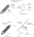
- FIGS. 2A through 2D depict structural mechanism of a plurality of components of the base frame 104 that transfer push from the UAV 106 to drive for one or more mopping systems, according to some embodiments of the present disclosure.
- the driver wheel frame 110 is connected to a rear end of the base frame 104.
- the pair of driving wheels 112 is attached to a lower side (or bottom side) of the driver wheel frame 110 at the rear end.
- the worm wheel 116B is attached to a driver wheel axle of the pair of driving wheels 112, which in turn drives the worm 116A about a vertical axis.
- 3D view of FIG. 2A depict structural mechanism of a plurality of components of the base frame 104 that transfer push from the UAV 106 to drive for one or more mopping systems, according to some embodiments of the present disclosure.
- the driver wheel frame 110 is connected to a rear end of the base frame 104.
- the pair of driving wheels 112 is attached to a lower side (or bottom side) of the driver wheel frame 110 at the
- the driver pulley 118 fixed at a top end of the worm 116A, wherein one or more driven pulley belts 120A-B transmit drive from the driver pulley 118 to one or more driven pulleys 122A-B further connected to one or more mopping systems 124A-B.
- the system 100 provides two embodiments, the single mopping system and dual mopping system.
- the choice of mode to be used is dependent on area of the surface of interest. For example, for a smaller area the single mopping system is a preferred choice at it reduces the payload of the UAV 106 to half and hence the cost.
- FIGS. 2E through 2G depict the mechanism of the mopping system 124 connected to the base frame 104 of the UPAMCS 100, according to some embodiments of the present disclosure.
- Each mopping system 124A-B has similar (or identical) mechanism for cleaning.
- the mopping system 124 includes the set of drive arms 126A driven by the driven pulley 120A attached further driving an epicyclic or planetary gear system.
- the planetary gear system comprises an annular gear wheel 130A fixed to the lower side of the base frame 104, a set of planet gear wheels 132A each connected to the drive arm among the set of drive arms 126A.
- the set of planet gear wheels 132A are meshed between fixed internal teeth of the annular gear wheel 130A and the sun gear wheel 128A, while each of the drive arm rotates the set of planet gear wheels 132A which in turn rotates the sun gear wheel 128A and a mopping material 134 fixed to a bottom side of the sun gear wheel 128A and the set of planet gear wheels 132A.
- the UPAMCS 100 is equipped with the cleaning fluid distribution network 136 attached to the base frame 104, which can operate differently for to address requirements of cleaning fluid spaying for an inclined surface and a flat surface.
- inclined surfaces include vertically mounted (90 degrees) glass panes or angularly mounted glass panes.
- the UAV 106 with UAV-MIM 102 can easily maneuver the moping systems at any angle with irregular shape surface.
- flat surfaces include floating or roof top solar panels and the like.
- the cleaning fluid distribution network 136 comprises (i) an inclined surface cleaning mechanism for spraying the cleaning fluid in an upward direction, and (ii) a flat surface cleaning mechanism for spraying the cleaning fluid in a downward direction for a surface to be cleaned below the one or more mopping systems 124A-B.
- FIG. 3A depicts 3-D view of construction of the cleaning fluid distribution network 136 mounted on the base frame 104 for cleaning a flat surface and an inclined surface during the first mode of operation (UPAMCS1), according to some embodiments of the present disclosure.
- FIG. 3B depicts construction of the cleaning fluid distribution network 136 mounted on the base frame for cleaning the flat surface and the inclined surface during the second mode of operation (UPAMCS2), according to some embodiments of the present disclosure.
- the inclined surface cleaning mechanism comprises the plurality of X-type cleaning fluid tanks 504 (elevated with head difference) and a plurality of Y-type nozzles 506 (in line with plane of inclined surface to be cleaned), which are electrically activated using the electrical nozzle actuation system 142A-B on receiving signals from the proximity sensors 144A-B and the vision cameras 138A-D.
- the cleaning fluid is sprayed via the piping network 508 to clean the inclined surface using one or more cylindrical surface cleaning rollers 502.
- the cylindrical surface cleaning rollers 502 is a single unit in FIG. 3A for single mopping system UPAMCS1, while the FIG. 3B depicts a split design for dual mopping system aligned in front of each mopping system 132A-B.
- the flat surface cleaning mechanism comprises a plurality of A-type cleaning fluid tanks 512 (at base frame level with head difference) and a plurality of B-type nozzles 514 (directed downwards towards flat surface to be cleaned), which are electrically activated using the electrical nozzle actuation system 142A-B on receiving signals from the proximity sensors 144A-B and the vision cameras 138A-D.
- the cleaning fluid is sprayed via the piping network 510 to clean the flat surface using one or more cylindrical surface cleaning rollers 502 and the one or more mopping systems 124A-B.
- the flow of the cleaning fluid is ensured by placing the cleaning fluid tanks to allow gravity flow.
- the UAV 106 is equipped with landing and take-off configurations, wherein the UAV-MIM 102 allows the UAV 106 to land and take-off vertically.
- a drive configuration of the UPAMCS 100 activated after landing on the surface enables utilizing a propulsive power of the UAV 106 to maximum for pushing the pair of driving wheel 112 and the driven wheels 114A-C using friction, wherein the pair of driving wheels 112 at the rear end of the base frame 104, and the driven wheels 114A-C attached to each of a front end, a Left Hand Side (LHS) and a Right Hand Side (RHS) of the base frame 104 push the UPAMCS 100 forward over the surface to be cleaned.
- LHS Left Hand Side
- RHS Right Hand Side
- the cleaning fluid distribution network 136 is activated as soon as the UPAMCS 100 lands and drives forward, spraying the cleaning fluid on the surface enabling the mopping system 124A-B to cleanse.
- One or more cylindrical surface cleaning rollers 502 installed in the front of the base frame 104 and supported at (i) the LHS, a middle side and the RHS of the UPAMCS base frame 104 for a two cylindrical surface cleaning rollers configuration, and (ii) at the LHS and the RHS for a single cylindrical surface cleaning roller configuration.
- the brushes are free to rotate about central axles.
- the electrical nozzle activation system 142A-B and the proximity sensor 144A-B can be controlled via on-board processing by the UAV 106 in accordance with the current UPAMCS configuration.
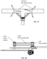
- FIG. 2H illustrates a visual based navigation system enabled by LiDARS 140A-D and one or more vision cameras 138A-D, each placed each end of the of the base frame 104.
- the visual information and LiDAR points captured by a visual based navigation system can be processed on-board by the UAV 106 enabling automatically and dynamically monitoring and tracking of the action of UPAMCS 100 over the surface to be cleaned. This also enables inspection of the surface.
- the processed information can be communicated to a central processing unit by the UAV 106 for further action to be initiated such as triggering damage alert, notifying cleaning task initiation or completion and so on to a remote administrator
- additional tactile or pressure sensors may be implemented for controlling the impact of the system (100) while landing, moving or in contact with surface to be cleaned, specifically for impact sensitive surfaces such as solar panels.
- the system may be equipped with a single LiDAR and placed at any one of the front end, rear end, LHS and RHS of the base frame 104, such that the single LiDAR provides the necessary views for navigation and control.
- the mopping system 124 works under three configurations comprising:
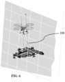
- FIG. 6 is a schematic depicting inclined surface cleaning mechanism by maintaining with the UAV in the lift configuration, wherein the system 100 moves up and down with the cylindrical surface cleaning rollers 502 pressing against the inclined surface such as a windowpane.
- Such computer-readable storage means contain program-code means for implementation of one or more steps of the method controlling the UAV configuration, when the program runs on a server or a device , for example, the embedded compiler or any edge device or any suitable programmable device.
- the hardware device can be any kind of device which can be programmed including e.g., any kind of computer like a server or a personal computer, or the like, or any combination thereof.
- the device may also include means which could be e.g., hardware means like e.g., an application-specific integrated circuit (ASIC), a field-programmable gate array (FPGA), or a combination of hardware and software means, e.g., an ASIC and an FPGA, or at least one microprocessor and at least one memory with software processing components located therein.
- the means can include both hardware means, and software means.
- the method embodiments described herein could be implemented in hardware and software.
- the device may also include software means. Alternatively, the embodiments may be implemented on different hardware devices, e.g., using a plurality of CPUs.
- a computer-readable storage medium refers to any type of physical memory on which information or data readable by a processor may be stored.
- a computer-readable storage medium may store instructions for execution by one or more processors, including instructions for causing the processor(s) to perform steps or stages consistent with the embodiments described herein.
- the term "computer-readable medium” should be understood to include tangible items and exclude carrier waves and transient signals, i.e., be non-transitory. Examples include random access memory (RAM), read-only memory (ROM), volatile memory, nonvolatile memory, hard drives, CD ROMs, DVDs, flash drives, disks, and any other known physical storage media.
Landscapes
- Engineering & Computer Science (AREA)
- General Engineering & Computer Science (AREA)
- Mechanical Engineering (AREA)
- Manufacturing & Machinery (AREA)
- Transportation (AREA)
- Aviation & Aerospace Engineering (AREA)
- Physics & Mathematics (AREA)
- Life Sciences & Earth Sciences (AREA)
- Sustainable Development (AREA)
- Sustainable Energy (AREA)
- Thermal Sciences (AREA)
- Chemical & Material Sciences (AREA)
- Combustion & Propulsion (AREA)
- Electric Vacuum Cleaner (AREA)
Abstract
Description
- The present application claims priority from
Indian patent application no. 202321019005, filed on March 21, 2023 - The disclosure herein generally relates to the field of automated surface cleaning systems, and, more particularly, to Unmanned Aerial Vehicle (UAV) Propelled Autonomous Multiplane Cleaning System (UPAMCS).
- Autonomous cleaning is in demand for solar panels with varying installation types including roof top solar paneling and floating solar panels spread over wide areas. Clean solar panels improve the efficiency of power generation. Similarly, developments in building and construction has led to high rise buildings, which mostly are covered with glass panes. Cleaning of these inclined glass panes is a regular task performed during building maintenance. Autonomous cleaning is one of the ideal options for cleaning of the above stated surfaces.
- Use of efficient methods for the surface cleaning tasks in terms of time, cost and power consumption is critical in automation approaches. One major reason being the sites of cleaning surfaces are generally remote with challenges faced in easy access to power recharging points. Many a times the sites are at remote places. Thus, on-board battery power must be efficiently used. However, conventional autonomous surface cleaners or solar panel cleaners such as autonomous mobile robots or drones used electrically powered motors for movement of a cleaning apparatus across the surface, as well as for activating the cleaning mechanism. Thus, the existing methods are power consuming systems, affecting time and cost of cleaning. One way to assess cleaning efficiency of the surface cleaners can be in terms of ratio of power consumed to area cleaned. Further, in addition to the power consumption aspect, the construct of the cleaning mechanism is critical.
- Cleaning systems proposed in the art have technical construct limitations in the cleaning mechanisms used, which lead to a lower ratio of power consumed to area cleaned, directly affecting the cleaning efficiency.
- Embodiments of the present disclosure present technological improvements as solutions to one or more of the above-mentioned technical problems recognized by the inventors in conventional systems. For example, in one embodiment, a system, also referred as Unmanned Aerial Vehicle (UAV) Propelled Autonomous Multiplane Cleaning System (UPAMCS), is provided.
- The system comprises a UAV and Mopping Interface Mechanism (UAV-MIM) mounted on a base frame connecting to a UAV as a slung load; a driver wheel frame connected to a rear end of the base frame, a pair of driving wheels attached to a lower side of the driver wheel frame at the rear end, a worm and a worm wheel, wherein the worm wheel is attached to a driver wheel axle of the pair of driving wheels, which in turn drives the worm about a vertical axis, a driver pulley fixed at a top end of the worm, wherein one or more driven pulley belts transmit drive from the driver pulley to one or more driven pulleys connecting one or more mopping systems.
- Each mopping system comprising: a set of drive arms driven by the driven pulley attached, an annular gear wheel fixed to the lower side of the base frame, a set of planet gear wheels, each planet gear wheel from the set of planet gear wheels connected to a drive arm among the set of drive arms, wherein the set of planet gear wheels are meshed between fixed internal teeth of the annular gear wheel and a sun gear wheel, while each of the drive arm rotates the set of planet gear wheels which in turn rotates the sun gear wheel and a mopping material fixed to a bottom side of the sun gear wheel and the set of planet gear wheels.
- The system further comprises a cleaning fluid distribution network attached to the base frame comprising (i) an inclined surface cleaning mechanism for spraying a cleaning fluid in upward direction and (ii) a flat surface cleaning mechanism for spraying the cleaning fluid in downward direction for a surface to be cleaned below the one or more mopping systems.
- It is to be understood that both the foregoing general description and the following detailed description are exemplary and explanatory only and are not restrictive of the invention, as claimed.
- The accompanying drawings, which are incorporated in and constitute a part of this disclosure, illustrate exemplary embodiments and, together with the description, serve to explain the disclosed principles:
-
FIG. 1A is a three-dimensional (3-D) view of a system, also referred to as an Unmanned Aerial Vehicle (UAV) Propelled Autonomous Multiplane Cleaning System (UPAMCS) in a first mode of operation comprising a single mopping system depicted in a lifting configuration, according to some embodiments of the present disclosure. -
FIG. 1B is a three-dimensional (3-D) view of the system (UPAMCS), in a second mode of operation comprising a dual mopping system depicted in a lifting configuration, according to some embodiments of the present disclosure. -
FIGS. 2A through 2D depict a structural mechanism of a plurality of components of a base frame of the UPAMCS that transfer forward push from a UAV to drive one or more mopping systems, according to some embodiments of the present disclosure. -
FIGS. 2E through 2G depict a mechanism of the mopping system connected to a base frame of the UPAMCS, according to some embodiments of the present disclosure. -
FIG. 2H illustrates vision cameras and Light Detection and Ranging (LiDARS) mounted on the base frame for tracking and monitoring landing and movement over surfaces, according to some embodiments of the present disclosure. -
FIG. 3A depicts construction of a cleaning fluid distribution network mounted on the base frame for cleaning a flat surface and an inclined surface during a first mode of operation (UPAMCS1), according to some embodiments of the present disclosure. -
FIG. 3B depicts construction of the cleaning fluid distribution network mounted on the base frame for cleaning the flat surface and the inclined surface during a second mode of operation (UPAMCS2), according to some embodiments of the present disclosure. -
FIG. 4A depicts a normal operating configuration of the first mode (UPAMCS1) andFIG. 4B depicts a steering configuration of the first mode (UPAMCS1), according to some embodiments of the present disclosure. -
FIG. 5A depicts the normal operating configuration of the second mode (UPAMCS2) andFIG. 5B depicts the steering configuration of the second mode (UPAMCS2), according to some embodiments of the present disclosure. -
FIG. 6 is a schematic depicting inclined surface cleaning mechanism by maintaining the UAV in the lifting configuration, wherein the system moves up and down with cylindrical surface cleaning rollers pressing against the inclined surface, according to some embodiments of the present disclosure. - It should be appreciated by those skilled in the art that any block diagrams herein represent conceptual views of illustrative systems and devices embodying the principles of the present subject matter. Similarly, it will be appreciated that any flow charts, flow diagrams, and the like represent various processes which may be substantially represented in computer readable medium and so executed by a computer or processor, whether or not such computer or processor is explicitly shown.
- Exemplary embodiments are described with reference to the accompanying drawings. In the figures, the left-most digit(s) of a reference number identifies the figure in which the reference number first appears. Wherever convenient, the same reference numbers are used throughout the drawings to refer to the same or like parts. While examples and features of disclosed principles are described herein, modifications, adaptations, and other implementations are possible without departing from the scope of the disclosed embodiments. It is intended that the following detailed description be considered as exemplary only, with the true scope being indicated by the following claims.
- Surface cleaning systems demand power, time, and cost efficient approaches. Cleaning systems proposed in the art have technical construct limitations in the cleaning mechanisms used, which leads to a lower ratio of power consumed to area cleaned, directly affecting the cleaning efficiency. Embodiments herein provide a system also referred to as an Unmanned Aerial Vehicle (UAV) Propelled Autonomous Multiplane Cleaning System (UPAMCS) for surface cleaning of flat and inclined surfaces. An UAV and Mopping Interface Mechanism (UAV-MIM) connects a UAV to one or more mopping systems comprising an epicyclic gear system, also referred to as planetary gear system, driven moppers with no additional power devices used. A maneuvering mechanism disclosed enables the UAV to propel the mopping systems to reach any geometric shape or inclination. The UPAMCS provides cost, time, and power efficient surface cleaning. The UPAMCS is also equipped with vision cameras and Light Detection and Ranging (LiDAR) for guidance during landing and crawling over surfaces along with additional surface defect detection by performing image processing on the captured images.
- Referring now to the drawings, and more particularly to
FIG. 1A through FIG. 6 , where similar reference characters denote corresponding features consistently throughout the figures, there are shown preferred embodiments and these embodiments are described in the context of the following exemplary system and/or method. Reference numerals of one or more components of the UPAMCS as depicted in theFIGS. 1A through 5B are provided in Table 1 below for ease of description:Table 1 Sl. No Component with alternative name Numeral reference 1 System (UAV Propelled Autonomous Multiplane Cleaning System (UPAMCS)) 100 2 UAV-MIM 102 3 Base frame (rear end, front end, Left Hand Side (LHS) and Right Hand Side (RHS) 104 4 UAV 106 5 UAV-MIM mounting 108A-D 6 Driving wheel frame 110 7 Pair of Driving wheels- Rear end 112 8 Driven wheels (front end, LHS, RHS) 114A-C 9 Worm 116A 10 Worm wheel 116B 11 Driver Pulley 118 12 Driven pulley belts 120A-B 13 Driven pulleys 122A-B 14 Mopping system 124A-B 15 Set of Drive arms 126A-B 16 Sun gear wheel 128A-B 17 Annular Gear wheel 130A-B 18 Set of planet gear wheels 132A-B 19 Mopping material 134 20 Cleaning Fluid Distribution Network 136 21 Vision cameras 138A-D 22 LiDARS 140A-D 23 Electrical nozzle actuation system 142A-B 24 Proximity sensors 144A-B 25 Cylindrical surface cleaning rollers 502 26 X-type cleaning fluid tanks (elevated with head difference) 504 27 Y-type nozzles (in line with plane of inclined surface to be cleaned) 506 28 Piping network for X-type cleaning fluid tanks 508 29 Piping network for A-type cleaning fluid tanks 510 30 A-type cleaning fluid tanks (at base frame level with head difference) 512 32 B-type nozzles (directed downwards towards flat surface to be cleaned) 514 - Irrespective of mode of operation, the mechanism for transfer of energy (forward movement) from the UAV to one or more the mopping system is the same and explained below, with specific design changes, to adapt to the two modes.
FIG. 1A is a three dimensional (3-D) view of thesystem 100, also referred to the UPAMCS, in the first mode (UPAMCS 1) of operation comprising a single mopping system depicted in a lifting configuration, according to some embodiments of the present disclosure.FIG. 1B is a three dimensional (3-D) view of the system 100 (UPAMCS), in a second mode of operation (UPAMCS2) comprising a dual mopping system depicted in a lifting configuration, according to some embodiments of the present disclosure. - As depicted in
FIG. 1A and1B , the UAV and Mopping Interface Mechanism (UAV-MIM) 102 is mounted on thebase frame 104 connecting to theUAV 106 as a slung load making the UPAMCS portable, which can be easily lifted and placed on surface to be cleaned. Thus, theUAV 106, for example a drone, functions as a primary driving system, wherein the UAV lifts thebase frame 104 mounted with the mopping systems via the UAV-MIM 102 with the lifting configuration. TheUAV 106 depicted inFIGS. 1A through FIG. 6 figure is only for illustration. As understood by person having ordinary skill in the art, an appropriate payload UAV can be selected in accordance with the end user requirements and constraints. The UAV-MIM 102 becomes vertical with theUAV 106 powered for lift off. Once thesystem 100 reaches the destination (surface to be cleaned), thesystem 100 lands gently and operating configuration is activated as depicted inFIG. 4A and5A . It can be understood that lift off, landing, and setting the UAV-MIM 102 into operation mode of interest is controlled via the UAV maneuvering. Thus, once thesystem 100 lands, theUAV 106 automatically rotates the UAV-MIM 104 to align approximately at 5 degrees to the surface panel horizon. This mechanism enables maximum thrust of theUAV 106 to be used for driving themopping system 124A-B. Thesystem 100 can be steered by the steering mechanism placed at thedrive wheel frame 110. The steering configuration is depicted in 4B and 4C. When theUAV 106 propels forward the pair of driving wheels 112 (at rear end of base frame 104) and the drivenwheels 114A-C connected in the front end, the LHS and the RHS of thebase frame 104 are moved by friction and thesystem 100 starts moving in either forward or backward, depending on the push direction of the drone with help of the steering mechanism. -
FIGS. 2A through 2D depict structural mechanism of a plurality of components of thebase frame 104 that transfer push from theUAV 106 to drive for one or more mopping systems, according to some embodiments of the present disclosure. As depicted in 3D view ofFIG. 2A , thedriver wheel frame 110 is connected to a rear end of thebase frame 104. The pair of drivingwheels 112 is attached to a lower side (or bottom side) of thedriver wheel frame 110 at the rear end. Theworm wheel 116B is attached to a driver wheel axle of the pair of drivingwheels 112, which in turn drives theworm 116A about a vertical axis. As depicted in the 3D view ofFIG. 2B , thedriver pulley 118 fixed at a top end of theworm 116A, wherein one or more drivenpulley belts 120A-B transmit drive from thedriver pulley 118 to one or more drivenpulleys 122A-B further connected to one ormore mopping systems 124A-B. - Thus, the
system 100 provides two embodiments, the single mopping system and dual mopping system. The choice of mode to be used is dependent on area of the surface of interest. For example, for a smaller area the single mopping system is a preferred choice at it reduces the payload of theUAV 106 to half and hence the cost. -
FIGS. 2E through 2G depict the mechanism of the mopping system 124 connected to thebase frame 104 of theUPAMCS 100, according to some embodiments of the present disclosure. Eachmopping system 124A-B has similar (or identical) mechanism for cleaning. As depicted in the 3D view ofFIG. 2E , top view of inFIG. 2F and sideview ofFIG. 2G , the mopping system 124 includes the set of drive arms 126A driven by the drivenpulley 120A attached further driving an epicyclic or planetary gear system. The planetary gear system comprises anannular gear wheel 130A fixed to the lower side of thebase frame 104, a set ofplanet gear wheels 132A each connected to the drive arm among the set of drive arms 126A. The set ofplanet gear wheels 132A are meshed between fixed internal teeth of theannular gear wheel 130A and thesun gear wheel 128A, while each of the drive arm rotates the set ofplanet gear wheels 132A which in turn rotates thesun gear wheel 128A and a moppingmaterial 134 fixed to a bottom side of thesun gear wheel 128A and the set ofplanet gear wheels 132A. - The
UPAMCS 100 is equipped with the cleaningfluid distribution network 136 attached to thebase frame 104, which can operate differently for to address requirements of cleaning fluid spaying for an inclined surface and a flat surface. Examples of inclined surfaces include vertically mounted (90 degrees) glass panes or angularly mounted glass panes. TheUAV 106 with UAV-MIM 102 can easily maneuver the moping systems at any angle with irregular shape surface. Examples of flat surfaces include floating or roof top solar panels and the like. The cleaningfluid distribution network 136 comprises (i) an inclined surface cleaning mechanism for spraying the cleaning fluid in an upward direction, and (ii) a flat surface cleaning mechanism for spraying the cleaning fluid in a downward direction for a surface to be cleaned below the one ormore mopping systems 124A-B.FIG. 3A depicts 3-D view of construction of the cleaningfluid distribution network 136 mounted on thebase frame 104 for cleaning a flat surface and an inclined surface during the first mode of operation (UPAMCS1), according to some embodiments of the present disclosure.FIG. 3B depicts construction of the cleaningfluid distribution network 136 mounted on the base frame for cleaning the flat surface and the inclined surface during the second mode of operation (UPAMCS2), according to some embodiments of the present disclosure. - As depicted in the 3-D view of
FIGS. 3A and3B , the inclined surface cleaning mechanism comprises the plurality of X-type cleaning fluid tanks 504 (elevated with head difference) and a plurality of Y-type nozzles 506 (in line with plane of inclined surface to be cleaned), which are electrically activated using the electricalnozzle actuation system 142A-B on receiving signals from theproximity sensors 144A-B and thevision cameras 138A-D. Once the Y-type nozzles 506 that are placed parallel to the inclined plane of the surface to be cleaned are activated, the cleaning fluid is sprayed via thepiping network 508 to clean the inclined surface using one or more cylindricalsurface cleaning rollers 502. The cylindricalsurface cleaning rollers 502 is a single unit inFIG. 3A for single mopping system UPAMCS1, while theFIG. 3B depicts a split design for dual mopping system aligned in front of eachmopping system 132A-B. - As depicted in
FIGS. 3A and3B , the flat surface cleaning mechanism comprises a plurality of A-type cleaning fluid tanks 512 (at base frame level with head difference) and a plurality of B-type nozzles 514 (directed downwards towards flat surface to be cleaned), which are electrically activated using the electricalnozzle actuation system 142A-B on receiving signals from theproximity sensors 144A-B and thevision cameras 138A-D. Once the B-type nozzles (514) that face towards the mopping system facing the surface to be cleaned are activated, the cleaning fluid is sprayed via thepiping network 510 to clean the flat surface using one or more cylindricalsurface cleaning rollers 502 and the one ormore mopping systems 124A-B. The flow of the cleaning fluid is ensured by placing the cleaning fluid tanks to allow gravity flow. - UPAMCS operation: The
UAV 106 is equipped with landing and take-off configurations, wherein the UAV-MIM 102 allows theUAV 106 to land and take-off vertically. A drive configuration of theUPAMCS 100 activated after landing on the surface enables utilizing a propulsive power of theUAV 106 to maximum for pushing the pair ofdriving wheel 112 and the drivenwheels 114A-C using friction, wherein the pair of drivingwheels 112 at the rear end of thebase frame 104, and the drivenwheels 114A-C attached to each of a front end, a Left Hand Side (LHS) and a Right Hand Side (RHS) of thebase frame 104 push theUPAMCS 100 forward over the surface to be cleaned. The cleaningfluid distribution network 136 is activated as soon as theUPAMCS 100 lands and drives forward, spraying the cleaning fluid on the surface enabling themopping system 124A-B to cleanse. One or more cylindricalsurface cleaning rollers 502 installed in the front of thebase frame 104 and supported at (i) the LHS, a middle side and the RHS of theUPAMCS base frame 104 for a two cylindrical surface cleaning rollers configuration, and (ii) at the LHS and the RHS for a single cylindrical surface cleaning roller configuration. The brushes are free to rotate about central axles. The electricalnozzle activation system 142A-B and theproximity sensor 144A-B can be controlled via on-board processing by theUAV 106 in accordance with the current UPAMCS configuration. -
FIG. 2H illustrates a visual based navigation system enabled byLiDARS 140A-D and one ormore vision cameras 138A-D, each placed each end of the of thebase frame 104. The visual information and LiDAR points captured by a visual based navigation system can be processed on-board by theUAV 106 enabling automatically and dynamically monitoring and tracking of the action ofUPAMCS 100 over the surface to be cleaned. This also enables inspection of the surface. The processed information can be communicated to a central processing unit by theUAV 106 for further action to be initiated such as triggering damage alert, notifying cleaning task initiation or completion and so on to a remote administrator In an embodiment, additional tactile or pressure sensors may be implemented for controlling the impact of the system (100) while landing, moving or in contact with surface to be cleaned, specifically for impact sensitive surfaces such as solar panels. In an embodiment the system may be equipped with a single LiDAR and placed at any one of the front end, rear end, LHS and RHS of thebase frame 104, such that the single LiDAR provides the necessary views for navigation and control. - The mopping system 124 works under three configurations comprising:
- a) The lifting configuration (as depicted in
FIGS. 1A and1B ), wherein the UAV-MIM mounting 108A-D is at 90 degree withUPAMCS base frame 104 making it feasible for themopping system 124A-B to be lifted during positioning (landing) and take-off. - b) A normal operating configuration (as depicted in
FIGS. 4A and5A ), wherein the pair of drivingwheels 112 and the drivenwheels 114A-C are moved by friction as a push from the UAV (106) when the UAV (106) propels in a specific direction. - c) A steering configuration (as depicted in
FIGS. 4B and5B ), wherein rotation of the pair of drivingwheels 112 in turn starts rotating theworm 116A and theworm wheel 116B mechanism which has a drive shaft attached over, the drive shaft in turn rotates thedriver pulley 118, wherein the rotation is transmitted to the drivenpulley 122A-B through the drivenpulley belts 120A-B. The drivenpulley 122A-B transmits the rotation to drive arms 126A-B that is passed through theUPAMCS base frame 104. The drive arms 126A-B transmit the rotation to the set ofplanet gear wheels 132A-B attached to the drive arms 126A-B, wherein the set ofplanet gear wheels 132A-B are meshed to the inner teeth of theannular gear wheel 130A-B and thesun gear wheel 128A-B for movement of the moppingmaterial 134 for cleaning the surface. -
FIG. 6 is a schematic depicting inclined surface cleaning mechanism by maintaining with the UAV in the lift configuration, wherein thesystem 100 moves up and down with the cylindricalsurface cleaning rollers 502 pressing against the inclined surface such as a windowpane. - Provided below is an illustrative 'cleaning time' calculation of the
system 100. - Nomenclature and specification of an
example system 100 considered is as below:- Driving wheel = dw: Dia = Ddw = 78.5 mm
- Worm gear = wg; No of teeth Twg = 20
- Worm = w; No. of starts of thread Nst = 2
- Driven pulley =dp; Driven pulley speed = Ndp
- Epicyclic arm =a; Arm speed = Na
- Planet gear = p; No of teeth = Tp = 75; module = 2
- Sun gear = s; No of teeth = Ts = 150; module = 2
- Design calculation for Solar Pond (SP) cleaning:
- a) System speed= Vdw = 3.6 m/s (Drone is assumed to provide)
- b) Driving wheel speed = Ndw = Vdw/(Ddw/2*2*Π/60) = 876 rpm
- c) Worm gear speed = Nwg = Ndw = 876 rpm
- d) Worm speed = Nw = (Twg/Nst) * Nwg = 87.6 rpm ≈ 88 rpm
- e) Planet gear speed = Np = Na = Ndp = Nw = 88 rpm
- f) Sun gear speed = Ns = Np * Tp/Ts = 44 rpm
- g) Cleaning time for SP:
- i. SP diameter = Dsp = 50 m
- ii. SP surface area = Asp = Π/4 * Dsp^2 =Π/4 * 50*50 m^2
- iii. Mopping wheel (MW) dia = Dmw = 0.6 m
- iv.MW area = Amw = Π/4 * Dmw^2 = Π/4 * 0.6*0.6 m^2
- v. Mopping system area = Ams =2*Amw = 2 * Π/4*0.6*0.6 m^2
- vi. No. of Dmw moved in 1 sec = Vdw/Dmw = 3.6/0.6 = 6
- vii. Area cleaned per sec = 6*Ams = 6 * 2 * Π/4 * 0.6*0.6 m^2
- viii. SP cleaning time= Asp/(6*Ams) = 578.7 s = 9 min 37 s
- h) As per the above calculation the
system 100 can clean the 50 m diameter solar plant in 9 min 37 s.
- The written description describes the subject matter herein to enable any person skilled in the art to make and use the embodiments. The scope of the subject matter embodiments is defined by the claims and may include other modifications that occur to those skilled in the art. Such other modifications are intended to be within the scope of the claims if they have similar elements that do not differ from the literal language of the claims or if they include equivalent elements with insubstantial differences from the literal language of the claims.
- It is to be understood that the scope of the protection is extended to such a program and in addition to a computer-readable means having a message therein; such computer-readable storage means contain program-code means for implementation of one or more steps of the method controlling the UAV configuration, when the program runs on a server or a device , for example, the embedded compiler or any edge device or any suitable programmable device. The hardware device can be any kind of device which can be programmed including e.g., any kind of computer like a server or a personal computer, or the like, or any combination thereof. The device may also include means which could be e.g., hardware means like e.g., an application-specific integrated circuit (ASIC), a field-programmable gate array (FPGA), or a combination of hardware and software means, e.g., an ASIC and an FPGA, or at least one microprocessor and at least one memory with software processing components located therein. Thus, the means can include both hardware means, and software means. The method embodiments described herein could be implemented in hardware and software. The device may also include software means. Alternatively, the embodiments may be implemented on different hardware devices, e.g., using a plurality of CPUs.
- The embodiments herein can comprise hardware and software elements. The embodiments that are implemented in software include but are not limited to, firmware, resident software, microcode, etc. The functions performed by various components described herein may be implemented in other components or combinations of other components. For the purposes of this description, a computer-usable or computer readable medium can be any apparatus that can comprise, store, communicate, propagate, or transport the program for use by or in connection with the instruction execution system, apparatus, or device.
- The illustrated steps are set out to explain the exemplary embodiments shown, and it should be anticipated that ongoing technological development will change the manner in which particular functions are performed. These examples are presented herein for purposes of illustration, and not limitation. Further, the boundaries of the functional building blocks have been arbitrarily defined herein for the convenience of the description. Alternative boundaries can be defined so long as the specified functions and relationships thereof are appropriately performed. Alternatives (including equivalents, extensions, variations, deviations, etc., of those described herein) will be apparent to persons skilled in the relevant art(s) based on the teachings contained herein. Such alternatives fall within the scope of the disclosed embodiments. Also, the words "comprising," "having," "containing," and "including," and other similar forms are intended to be equivalent in meaning and be open ended in that an item or items following any one of these words is not meant to be an exhaustive listing of such item or items or meant to be limited to only the listed item or items. It must also be noted that as used herein and in the appended claims, the singular forms "a," "an," and "the" include plural references unless the context clearly dictates otherwise.
- Furthermore, one or more computer-readable storage media may be utilized in implementing embodiments consistent with the present disclosure. A computer-readable storage medium refers to any type of physical memory on which information or data readable by a processor may be stored. Thus, a computer-readable storage medium may store instructions for execution by one or more processors, including instructions for causing the processor(s) to perform steps or stages consistent with the embodiments described herein. The term "computer-readable medium" should be understood to include tangible items and exclude carrier waves and transient signals, i.e., be non-transitory. Examples include random access memory (RAM), read-only memory (ROM), volatile memory, nonvolatile memory, hard drives, CD ROMs, DVDs, flash drives, disks, and any other known physical storage media.
- It is intended that the disclosure and examples be considered as exemplary only, with a true scope of disclosed embodiments being indicated by the following claims.
Claims (8)
- An Unmanned Aerial Vehicle (UAV) Propelled Autonomous Multiplane Cleaning System (UPAMCS) (100), comprising:a UAV and Mopping Interface Mechanism (UAV-MIM) (102) mounted on a base frame (104) connecting to a UAV (106) as a slung load;a driver wheel frame (110) connected to a rear end of the base frame (104);a pair of driving wheels (112) attached to a lower side of the driver wheel frame (110) at the rear end, a worm (116A) and a worm wheel (116B), wherein the worm wheel (116B) is attached to a driver wheel axle of the pair of driving wheels (112), which in turn drives the worm (116A) about a vertical axis;a driver pulley (118) fixed at a top end of the worm (116A), wherein one or more driven pulley belts (120A-B) transmit drive from the driver pulley (118) to one or more driven pulleys (122A-B) connecting one or more mopping systems (124A-B),each mopping system (124A) comprising:a set of drive arms (126A) driven by the driven pulley (122A) attached;an annular gear wheel (130A) fixed to the lower side of the base frame (104); anda set of planet gear wheels (132A), each planet gear wheel from the set of planet gear wheels (132A) is connected to a drive arm among the set of drive arms (126A), wherein the set of planet gear wheels (132A) is meshed between fixed internal teeth of the annular gear wheel (130A) and a sun gear wheel (128A), wherein each of the drive arm rotates the set of planet gear wheels (132A) which in turn rotate the sun gear wheel (128A) and a mopping material (134) fixed to a bottom side of the sun gear wheel (128A) and the set of planet gear wheels (132A); anda cleaning fluid distribution network (136) attached to the base frame (104) comprising (i) an inclined surface cleaning mechanism for spraying cleaning fluid in an upward direction and (ii) a flat surface cleaning mechanism for spraying the cleaning fluid in a downward direction for a surface to be cleaned below the one or more mopping systems (124A-B).
- The UPAMCS (100) as claimed in claim 1, wherein the inclined surface cleaning mechanism comprises a plurality of X-type cleaning fluid tanks (504) and a plurality of Y-type nozzles (506), which are electrically actuated via an electrical nozzle actuation system (142B) for spraying the cleaning fluid to clean an inclined surface using one or more cylindrical surface cleaning rollers (502).
- The UPAMCS (100) as claimed in claim 1, wherein the flat surface cleaning mechanism comprises a plurality of A-type cleaning fluid tanks (512) and a plurality of B-type nozzles (514), which are electrically activated via the electrical nozzle actuation system (142A) for spraying the cleaning fluid to clean a flat surface using one or more cylindrical surface cleaning rollers (502) and the one or more mopping systems (124A-B).
- The UPAMCS (100) as claimed in claim 1, wherein the UAV (106) is equipped with landing and take-off configurations, and wherein the UAV-MIM (102) allows the UAV (106) to land and take-off vertically.
- The UPAMCS (100) as claimed in claim 4, wherein the UPAMCS (100) operates in a first mode (UPAMCS1) with a single mopping system and a second mode (UPAMCS2) with a dual mopping system.
- The UPAMCS (100) as claimed in claim 4, whereina drive configuration of the UPAMCS (100) activated after landing on the surface enables utilizing a propulsive power of the UAV (106) to maximum for the pair of driving wheel (112) and the driven wheels (114A-C) using friction, wherein the pair of driving wheels (112) at the rear end of the base frame (104), and driven wheels (114A-C) attached to each of a front end, a Left Hand Side (LHS) and a Right Hand Side (RHS) of the base frame (104) push the UPAMCS (100) forward over the surface to be cleaned,the cleaning fluid distribution network (136) is activated when the UPAMCS (100) lands and drives forward, spraying the cleaning fluid on the surface enabling the mopping system (124A-B) to cleanse, andone or more cylindrical surface cleaning rollers (502) installed in the front of the base frame (104) and supported at (i) the LHS, a middle side and the RHS of the base frame (104) for a two cylindrical surface cleaning rollers configuration, and (ii) at the LHS and the RHS for a single cylindrical surface cleaning roller configuration, wherein the brushes are configured to freely rotate about central axles.
- The UPAMCS (100) as claimed in claim 1, comprises a visual based navigation system enabled by one or more LiDARS (140A-D), and one or more vision cameras (138A-D) placed at the front end, the rear end, the LHS and the RHS of the base frame (104).
- The UPAMCS (100) as claimed in claim 1, wherein the mopping system (124A-B) is operated with a plurality of configurations comprising:a lifting configuration, wherein a UAV-MIM mounting (108A-D) is at 90 degree with the base frame (104) enabling the mopping system (124A-B) to be lifted during landing and take-off;a normal operating configuration, wherein in the normal operating configuration the pair of driving wheels (112) and the driven wheels (114A-C) are moved by friction as a push from the UAV (106) when the UAV (106) propels in a specific direction;a steering configuration, wherein in the steering configuration rotation of the pair of driving wheels (112) in turn starts rotating the worm (116A) and the worm wheel (116B) which has a drive shaft attached over, the drive shaft in turn rotates the driver pulley (118), and wherein the rotation is transmitted to the driven pulley (122A-B) through the one or more driven pulley belts (120A-B);the driven pulley (122A-B) transmits the rotation to the set of drive arms (126A-B) that is passed through the base frame (104), wherein the set of drive arms (126A-B) transmit the rotation to the set of planet gear wheels (132A-B) attached to the set of drive arms (126A-B), wherein the set of planet gear wheels (132A-B) is meshed to the inner teeth of the annular gear wheel (130A-B) and the sun gear wheel (128A-B) for movement of the mopping material (134) for cleaning the surface.
Applications Claiming Priority (1)
| Application Number | Priority Date | Filing Date | Title |
|---|---|---|---|
| IN202321019005 | 2023-03-21 |
Publications (3)
| Publication Number | Publication Date |
|---|---|
| EP4435345A1 true EP4435345A1 (en) | 2024-09-25 |
| EP4435345B1 EP4435345B1 (en) | 2025-06-11 |
| EP4435345C0 EP4435345C0 (en) | 2025-06-11 |
Family
ID=90365587
Family Applications (1)
| Application Number | Title | Priority Date | Filing Date |
|---|---|---|---|
| EP24163407.0A Active EP4435345B1 (en) | 2023-03-21 | 2024-03-14 | Unmanned aerial vehicle propelled autonomous multiplane cleaning system |
Country Status (2)
| Country | Link |
|---|---|
| US (1) | US20240317425A1 (en) |
| EP (1) | EP4435345B1 (en) |
Families Citing this family (2)
| Publication number | Priority date | Publication date | Assignee | Title |
|---|---|---|---|---|
| CN117762161B (en) * | 2024-02-22 | 2024-06-04 | 内蒙古工业大学 | A cleaning system and method suitable for ultra-large-scale photovoltaic power stations |
| CN119368463A (en) * | 2024-10-21 | 2025-01-28 | 重庆千信新能源有限公司 | An automatic cleaning robot for photovoltaic operation and maintenance |
Citations (9)
| Publication number | Priority date | Publication date | Assignee | Title |
|---|---|---|---|---|
| CN209174516U (en) * | 2018-12-08 | 2019-07-30 | 河南瑞恒电力电气有限公司 | A kind of photovoltaic plant and glass curtain wall cleaning flight deduster |
| CN213243914U (en) * | 2020-08-19 | 2021-05-18 | 天津金盛吉达新能源科技有限公司 | Photovoltaic board cleaning device who possesses unmanned aerial vehicle flight control |
| CN216468481U (en) * | 2021-12-30 | 2022-05-10 | 焱图慧云(苏州)信息科技有限公司 | Be used for abluent unmanned aerial vehicle of photovoltaic board |
| WO2022097171A1 (en) * | 2020-11-03 | 2022-05-12 | Mohan Suraj | Autonomous dynamic cleaning system for photovoltaic panels and method thereof |
| CN114560085A (en) * | 2022-02-22 | 2022-05-31 | 北京空天技术研究所 | Unmanned aerial vehicle device and system for autonomous cleaning and maintenance of solar photovoltaic panel |
| CN115158664A (en) * | 2022-07-27 | 2022-10-11 | 武汉稀云科技有限公司 | A kind of cleaning drone structure and using method |
| CN113060281B (en) * | 2021-03-18 | 2022-11-15 | 华北电力大学(保定) | Photovoltaic power station photovoltaic panel cleaning system using unmanned aerial vehicle and cleaning robot |
| DE102021112751A1 (en) * | 2021-05-17 | 2022-11-17 | Hochschule für Technik und Wirtschaft Berlin, Körperschaft des öffentlichen Rechts | Cleaning device for automatically cleaning solar modules of a solar system |
| KR20230000518A (en) * | 2021-06-24 | 2023-01-03 | 이재근 | Drone for cleaning solar module |
-
2024
- 2024-03-14 US US18/604,817 patent/US20240317425A1/en active Pending
- 2024-03-14 EP EP24163407.0A patent/EP4435345B1/en active Active
Patent Citations (9)
| Publication number | Priority date | Publication date | Assignee | Title |
|---|---|---|---|---|
| CN209174516U (en) * | 2018-12-08 | 2019-07-30 | 河南瑞恒电力电气有限公司 | A kind of photovoltaic plant and glass curtain wall cleaning flight deduster |
| CN213243914U (en) * | 2020-08-19 | 2021-05-18 | 天津金盛吉达新能源科技有限公司 | Photovoltaic board cleaning device who possesses unmanned aerial vehicle flight control |
| WO2022097171A1 (en) * | 2020-11-03 | 2022-05-12 | Mohan Suraj | Autonomous dynamic cleaning system for photovoltaic panels and method thereof |
| CN113060281B (en) * | 2021-03-18 | 2022-11-15 | 华北电力大学(保定) | Photovoltaic power station photovoltaic panel cleaning system using unmanned aerial vehicle and cleaning robot |
| DE102021112751A1 (en) * | 2021-05-17 | 2022-11-17 | Hochschule für Technik und Wirtschaft Berlin, Körperschaft des öffentlichen Rechts | Cleaning device for automatically cleaning solar modules of a solar system |
| KR20230000518A (en) * | 2021-06-24 | 2023-01-03 | 이재근 | Drone for cleaning solar module |
| CN216468481U (en) * | 2021-12-30 | 2022-05-10 | 焱图慧云(苏州)信息科技有限公司 | Be used for abluent unmanned aerial vehicle of photovoltaic board |
| CN114560085A (en) * | 2022-02-22 | 2022-05-31 | 北京空天技术研究所 | Unmanned aerial vehicle device and system for autonomous cleaning and maintenance of solar photovoltaic panel |
| CN115158664A (en) * | 2022-07-27 | 2022-10-11 | 武汉稀云科技有限公司 | A kind of cleaning drone structure and using method |
Also Published As
| Publication number | Publication date |
|---|---|
| EP4435345B1 (en) | 2025-06-11 |
| EP4435345C0 (en) | 2025-06-11 |
| US20240317425A1 (en) | 2024-09-26 |
Similar Documents
| Publication | Publication Date | Title |
|---|---|---|
| US20240317425A1 (en) | Unmanned aerial vehicle (uav) propelled autonomous multiplane cleaning system (upamcs) | |
| CN110667719B (en) | Marine omnidirectional movement wall climbing robot | |
| KR102486884B1 (en) | Cleaning robot and cleaning system using the same | |
| US12018509B2 (en) | Pool-cleaning robot | |
| EP3126067B1 (en) | Agcfds: automated glass cleaning flying drone system | |
| US9844990B2 (en) | Multiple environment unmanned vehicle | |
| KR101984202B1 (en) | Cleaning system for solar panel using drone | |
| KR101779667B1 (en) | Solar cell cleaning robot and cleaning method using the same | |
| US20240076071A1 (en) | Aerial vehicle also capable of moving on inclined surfaces | |
| JP2025157474A (en) | Construction machinery | |
| CN108819630A (en) | A kind of land, water and air Bi Duoqi robot and its control method | |
| CN112478010B (en) | Underwater cruising and wall-climbing dual-mode robot | |
| CN108819631A (en) | Two rotor balance car land, water and air Duo Qi robots of one kind and its control method | |
| KR101795677B1 (en) | Hybrid drone having common frame | |
| CN108638773A (en) | The wheeled land, water and air of a kind of three rotors three are dwelt robot | |
| KR101516542B1 (en) | Cleaning robot used for ship, and method of attaching and retrieving the same to/from ship surface | |
| CN112829846B (en) | Wall climbing robot and wall transition method thereof | |
| CN114536362A (en) | Flexible aircraft paint removal robot and use method thereof | |
| CN117818267A (en) | Air-ground dual-purpose rescue robot and deformation method | |
| JP4220941B2 (en) | Power transmission device for flying object | |
| KR20160086130A (en) | moving apparatus | |
| JP7495696B1 (en) | Cleaning drones and cleaning systems | |
| FR3125017A1 (en) | Wired drone for the treatment of a surface of a building by a treatment fluid. | |
| CN121693451A (en) | Robotic system and method employing an actuated movable actuator mount and a passive flexible arm | |
| CN110906106A (en) | Crawling robot walking mechanism and crawling robot |
Legal Events
| Date | Code | Title | Description |
|---|---|---|---|
| PUAI | Public reference made under article 153(3) epc to a published international application that has entered the european phase |
Free format text: ORIGINAL CODE: 0009012 |
|
| STAA | Information on the status of an ep patent application or granted ep patent |
Free format text: STATUS: THE APPLICATION HAS BEEN PUBLISHED |
|
| AK | Designated contracting states |
Kind code of ref document: A1 Designated state(s): AL AT BE BG CH CY CZ DE DK EE ES FI FR GB GR HR HU IE IS IT LI LT LU LV MC ME MK MT NL NO PL PT RO RS SE SI SK SM TR |
|
| STAA | Information on the status of an ep patent application or granted ep patent |
Free format text: STATUS: REQUEST FOR EXAMINATION WAS MADE |
|
| 17P | Request for examination filed |
Effective date: 20241125 |
|
| RBV | Designated contracting states (corrected) |
Designated state(s): AL AT BE BG CH CY CZ DE DK EE ES FI FR GB GR HR HU IE IS IT LI LT LU LV MC ME MK MT NL NO PL PT RO RS SE SI SK SM TR |
|
| GRAP | Despatch of communication of intention to grant a patent |
Free format text: ORIGINAL CODE: EPIDOSNIGR1 |
|
| STAA | Information on the status of an ep patent application or granted ep patent |
Free format text: STATUS: GRANT OF PATENT IS INTENDED |
|
| RIC1 | Information provided on ipc code assigned before grant |
Ipc: B08B 3/02 20060101ALI20250122BHEP Ipc: B08B 1/36 20240101ALI20250122BHEP Ipc: B08B 1/34 20240101ALI20250122BHEP Ipc: B08B 1/30 20240101ALI20250122BHEP Ipc: B08B 1/14 20240101ALI20250122BHEP Ipc: H02S 40/10 20140101ALI20250122BHEP Ipc: F24S 40/20 20180101AFI20250122BHEP |
|
| INTG | Intention to grant announced |
Effective date: 20250207 |
|
| GRAS | Grant fee paid |
Free format text: ORIGINAL CODE: EPIDOSNIGR3 |
|
| GRAA | (expected) grant |
Free format text: ORIGINAL CODE: 0009210 |
|
| STAA | Information on the status of an ep patent application or granted ep patent |
Free format text: STATUS: THE PATENT HAS BEEN GRANTED |
|
| AK | Designated contracting states |
Kind code of ref document: B1 Designated state(s): AL AT BE BG CH CY CZ DE DK EE ES FI FR GB GR HR HU IE IS IT LI LT LU LV MC ME MK MT NL NO PL PT RO RS SE SI SK SM TR |
|
| REG | Reference to a national code |
Ref country code: GB Ref legal event code: FG4D |
|
| REG | Reference to a national code |
Ref country code: CH Ref legal event code: EP |
|
| REG | Reference to a national code |
Ref country code: IE Ref legal event code: FG4D |
|
| REG | Reference to a national code |
Ref country code: DE Ref legal event code: R096 Ref document number: 602024000190 Country of ref document: DE |
|
| U01 | Request for unitary effect filed |
Effective date: 20250611 |
|
| U07 | Unitary effect registered |
Designated state(s): AT BE BG DE DK EE FI FR IT LT LU LV MT NL PT RO SE SI Effective date: 20250620 |
|
| PG25 | Lapsed in a contracting state [announced via postgrant information from national office to epo] |
Ref country code: ES Free format text: LAPSE BECAUSE OF FAILURE TO SUBMIT A TRANSLATION OF THE DESCRIPTION OR TO PAY THE FEE WITHIN THE PRESCRIBED TIME-LIMIT Effective date: 20250611 |
|
| PG25 | Lapsed in a contracting state [announced via postgrant information from national office to epo] |
Ref country code: GR Free format text: LAPSE BECAUSE OF FAILURE TO SUBMIT A TRANSLATION OF THE DESCRIPTION OR TO PAY THE FEE WITHIN THE PRESCRIBED TIME-LIMIT Effective date: 20250912 Ref country code: NO Free format text: LAPSE BECAUSE OF FAILURE TO SUBMIT A TRANSLATION OF THE DESCRIPTION OR TO PAY THE FEE WITHIN THE PRESCRIBED TIME-LIMIT Effective date: 20250911 |
|
| PG25 | Lapsed in a contracting state [announced via postgrant information from national office to epo] |
Ref country code: HR Free format text: LAPSE BECAUSE OF FAILURE TO SUBMIT A TRANSLATION OF THE DESCRIPTION OR TO PAY THE FEE WITHIN THE PRESCRIBED TIME-LIMIT Effective date: 20250611 |
|
| PG25 | Lapsed in a contracting state [announced via postgrant information from national office to epo] |
Ref country code: RS Free format text: LAPSE BECAUSE OF FAILURE TO SUBMIT A TRANSLATION OF THE DESCRIPTION OR TO PAY THE FEE WITHIN THE PRESCRIBED TIME-LIMIT Effective date: 20250911 |
|
| PG25 | Lapsed in a contracting state [announced via postgrant information from national office to epo] |
Ref country code: IS Free format text: LAPSE BECAUSE OF FAILURE TO SUBMIT A TRANSLATION OF THE DESCRIPTION OR TO PAY THE FEE WITHIN THE PRESCRIBED TIME-LIMIT Effective date: 20251011 |
|
| PG25 | Lapsed in a contracting state [announced via postgrant information from national office to epo] |
Ref country code: SM Free format text: LAPSE BECAUSE OF FAILURE TO SUBMIT A TRANSLATION OF THE DESCRIPTION OR TO PAY THE FEE WITHIN THE PRESCRIBED TIME-LIMIT Effective date: 20250611 |
|
| PG25 | Lapsed in a contracting state [announced via postgrant information from national office to epo] |
Ref country code: CZ Free format text: LAPSE BECAUSE OF FAILURE TO SUBMIT A TRANSLATION OF THE DESCRIPTION OR TO PAY THE FEE WITHIN THE PRESCRIBED TIME-LIMIT Effective date: 20250611 |
|
| PG25 | Lapsed in a contracting state [announced via postgrant information from national office to epo] |
Ref country code: PL Free format text: LAPSE BECAUSE OF FAILURE TO SUBMIT A TRANSLATION OF THE DESCRIPTION OR TO PAY THE FEE WITHIN THE PRESCRIBED TIME-LIMIT Effective date: 20250611 |
|
| PG25 | Lapsed in a contracting state [announced via postgrant information from national office to epo] |
Ref country code: SK Free format text: LAPSE BECAUSE OF FAILURE TO SUBMIT A TRANSLATION OF THE DESCRIPTION OR TO PAY THE FEE WITHIN THE PRESCRIBED TIME-LIMIT Effective date: 20250611 |
|
| PLBE | No opposition filed within time limit |
Free format text: ORIGINAL CODE: 0009261 |
|
| STAA | Information on the status of an ep patent application or granted ep patent |
Free format text: STATUS: NO OPPOSITION FILED WITHIN TIME LIMIT |
|
| REG | Reference to a national code |
Ref country code: CH Ref legal event code: L10 Free format text: ST27 STATUS EVENT CODE: U-0-0-L10-L00 (AS PROVIDED BY THE NATIONAL OFFICE) Effective date: 20260423 |
|
| U20 | Renewal fee for the european patent with unitary effect paid |
Year of fee payment: 3 Effective date: 20260323 |