EP4435342A1 - Method and apparatus for unit control and photovoltaic multi-unit air conditioning system - Google Patents
Method and apparatus for unit control and photovoltaic multi-unit air conditioning system Download PDFInfo
- Publication number
- EP4435342A1 EP4435342A1 EP22921540.5A EP22921540A EP4435342A1 EP 4435342 A1 EP4435342 A1 EP 4435342A1 EP 22921540 A EP22921540 A EP 22921540A EP 4435342 A1 EP4435342 A1 EP 4435342A1
- Authority
- EP
- European Patent Office
- Prior art keywords
- current unit
- unit
- case
- power supplied
- photovoltaic power
- Prior art date
- Legal status (The legal status is an assumption and is not a legal conclusion. Google has not performed a legal analysis and makes no representation as to the accuracy of the status listed.)
- Pending
Links
Images


Classifications
-
- F—MECHANICAL ENGINEERING; LIGHTING; HEATING; WEAPONS; BLASTING
- F24—HEATING; RANGES; VENTILATING
- F24F—AIR-CONDITIONING; AIR-HUMIDIFICATION; VENTILATION; USE OF AIR CURRENTS FOR SCREENING
- F24F5/00—Air-conditioning systems or apparatus not covered by F24F1/00 or F24F3/00, e.g. using solar heat or combined with household units such as an oven or water heater
- F24F5/0046—Air-conditioning systems or apparatus not covered by F24F1/00 or F24F3/00, e.g. using solar heat or combined with household units such as an oven or water heater using natural energy, e.g. solar energy, energy from the ground
-
- F—MECHANICAL ENGINEERING; LIGHTING; HEATING; WEAPONS; BLASTING
- F24—HEATING; RANGES; VENTILATING
- F24F—AIR-CONDITIONING; AIR-HUMIDIFICATION; VENTILATION; USE OF AIR CURRENTS FOR SCREENING
- F24F11/00—Control or safety arrangements
- F24F11/88—Electrical aspects, e.g. circuits
-
- F—MECHANICAL ENGINEERING; LIGHTING; HEATING; WEAPONS; BLASTING
- F24—HEATING; RANGES; VENTILATING
- F24F—AIR-CONDITIONING; AIR-HUMIDIFICATION; VENTILATION; USE OF AIR CURRENTS FOR SCREENING
- F24F11/00—Control or safety arrangements
- F24F11/62—Control or safety arrangements characterised by the type of control or by internal processing, e.g. using fuzzy logic, adaptive control or estimation of values
- F24F11/63—Electronic processing
- F24F11/64—Electronic processing using pre-stored data
-
- F—MECHANICAL ENGINEERING; LIGHTING; HEATING; WEAPONS; BLASTING
- F24—HEATING; RANGES; VENTILATING
- F24F—AIR-CONDITIONING; AIR-HUMIDIFICATION; VENTILATION; USE OF AIR CURRENTS FOR SCREENING
- F24F11/00—Control or safety arrangements
- F24F11/62—Control or safety arrangements characterised by the type of control or by internal processing, e.g. using fuzzy logic, adaptive control or estimation of values
- F24F11/63—Electronic processing
- F24F11/65—Electronic processing for selecting an operating mode
-
- F—MECHANICAL ENGINEERING; LIGHTING; HEATING; WEAPONS; BLASTING
- F24—HEATING; RANGES; VENTILATING
- F24F—AIR-CONDITIONING; AIR-HUMIDIFICATION; VENTILATION; USE OF AIR CURRENTS FOR SCREENING
- F24F11/00—Control or safety arrangements
- F24F11/89—Arrangement or mounting of control or safety devices
-
- G—PHYSICS
- G05—CONTROLLING; REGULATING
- G05F—SYSTEMS FOR REGULATING ELECTRIC OR MAGNETIC VARIABLES
- G05F1/00—Automatic systems in which deviations of an electric quantity from one or more predetermined values are detected at the output of the system and fed back to a device within the system to restore the detected quantity to its predetermined value or values, i.e. retroactive systems
- G05F1/66—Regulating electric power
- G05F1/67—Regulating electric power to the maximum power available from a generator, e.g. from solar cell
-
- H—ELECTRICITY
- H02—GENERATION; CONVERSION OR DISTRIBUTION OF ELECTRIC POWER
- H02J—ELECTRIC POWER NETWORKS; CIRCUIT ARRANGEMENTS OR SYSTEMS FOR SUPPLYING OR DISTRIBUTING ELECTRIC POWER; SYSTEMS FOR STORING ELECTRIC ENERGY
- H02J3/00—Circuit arrangements for AC mains or AC distribution networks
- H02J3/12—Arrangements for adjusting voltage in AC networks by changing a characteristic of the network load
- H02J3/14—Arrangements for adjusting voltage in AC networks by changing a characteristic of the network load by switching loads on to, or off from, the networks, e.g. progressively balanced loading
-
- H—ELECTRICITY
- H02—GENERATION; CONVERSION OR DISTRIBUTION OF ELECTRIC POWER
- H02J—ELECTRIC POWER NETWORKS; CIRCUIT ARRANGEMENTS OR SYSTEMS FOR SUPPLYING OR DISTRIBUTING ELECTRIC POWER; SYSTEMS FOR STORING ELECTRIC ENERGY
- H02J3/00—Circuit arrangements for AC mains or AC distribution networks
- H02J3/38—Arrangements for feeding a single network from two or more generators or sources in parallel; Arrangements for feeding already energised networks from additional generators or sources in parallel
- H02J3/381—Dispersed generators
-
- H—ELECTRICITY
- H02—GENERATION; CONVERSION OR DISTRIBUTION OF ELECTRIC POWER
- H02J—ELECTRIC POWER NETWORKS; CIRCUIT ARRANGEMENTS OR SYSTEMS FOR SUPPLYING OR DISTRIBUTING ELECTRIC POWER; SYSTEMS FOR STORING ELECTRIC ENERGY
- H02J3/00—Circuit arrangements for AC mains or AC distribution networks
- H02J3/38—Arrangements for feeding a single network from two or more generators or sources in parallel; Arrangements for feeding already energised networks from additional generators or sources in parallel
- H02J3/46—Controlling the sharing of generated power between the generators, sources or networks
-
- H—ELECTRICITY
- H02—GENERATION; CONVERSION OR DISTRIBUTION OF ELECTRIC POWER
- H02J—ELECTRIC POWER NETWORKS; CIRCUIT ARRANGEMENTS OR SYSTEMS FOR SUPPLYING OR DISTRIBUTING ELECTRIC POWER; SYSTEMS FOR STORING ELECTRIC ENERGY
- H02J7/00—Circuit arrangements for charging or discharging batteries or for supplying loads from batteries
- H02J7/34—Parallel operation in networks using both storage and other DC sources, e.g. providing buffering
- H02J7/35—Parallel operation in networks using both storage and other DC sources, e.g. providing buffering with light sensitive cells
-
- H—ELECTRICITY
- H02—GENERATION; CONVERSION OR DISTRIBUTION OF ELECTRIC POWER
- H02M—APPARATUS FOR CONVERSION BETWEEN AC AND AC, BETWEEN AC AND DC, OR BETWEEN DC AND DC, AND FOR USE WITH MAINS OR SIMILAR POWER SUPPLY SYSTEMS; CONVERSION OF DC OR AC INPUT POWER INTO SURGE OUTPUT POWER; CONTROL OR REGULATION THEREOF
- H02M1/00—Details of apparatus for conversion
- H02M1/32—Means for protecting converters other than automatic disconnection
- H02M1/327—Means for protecting converters other than automatic disconnection against abnormal temperatures
-
- F—MECHANICAL ENGINEERING; LIGHTING; HEATING; WEAPONS; BLASTING
- F24—HEATING; RANGES; VENTILATING
- F24F—AIR-CONDITIONING; AIR-HUMIDIFICATION; VENTILATION; USE OF AIR CURRENTS FOR SCREENING
- F24F5/00—Air-conditioning systems or apparatus not covered by F24F1/00 or F24F3/00, e.g. using solar heat or combined with household units such as an oven or water heater
- F24F5/0046—Air-conditioning systems or apparatus not covered by F24F1/00 or F24F3/00, e.g. using solar heat or combined with household units such as an oven or water heater using natural energy, e.g. solar energy, energy from the ground
- F24F2005/0064—Air-conditioning systems or apparatus not covered by F24F1/00 or F24F3/00, e.g. using solar heat or combined with household units such as an oven or water heater using natural energy, e.g. solar energy, energy from the ground using solar energy
- F24F2005/0067—Air-conditioning systems or apparatus not covered by F24F1/00 or F24F3/00, e.g. using solar heat or combined with household units such as an oven or water heater using natural energy, e.g. solar energy, energy from the ground using solar energy with photovoltaic panels
-
- H—ELECTRICITY
- H02—GENERATION; CONVERSION OR DISTRIBUTION OF ELECTRIC POWER
- H02J—ELECTRIC POWER NETWORKS; CIRCUIT ARRANGEMENTS OR SYSTEMS FOR SUPPLYING OR DISTRIBUTING ELECTRIC POWER; SYSTEMS FOR STORING ELECTRIC ENERGY
- H02J2101/00—Supply or distribution of decentralised, dispersed or local electric power generation
- H02J2101/20—Dispersed power generation using renewable energy sources
- H02J2101/22—Solar energy
- H02J2101/24—Photovoltaics
-
- H—ELECTRICITY
- H02—GENERATION; CONVERSION OR DISTRIBUTION OF ELECTRIC POWER
- H02J—ELECTRIC POWER NETWORKS; CIRCUIT ARRANGEMENTS OR SYSTEMS FOR SUPPLYING OR DISTRIBUTING ELECTRIC POWER; SYSTEMS FOR STORING ELECTRIC ENERGY
- H02J2101/00—Supply or distribution of decentralised, dispersed or local electric power generation
- H02J2101/20—Dispersed power generation using renewable energy sources
- H02J2101/22—Solar energy
- H02J2101/24—Photovoltaics
- H02J2101/25—Photovoltaics involving maximum power point tracking control for photovoltaic sources
-
- Y—GENERAL TAGGING OF NEW TECHNOLOGICAL DEVELOPMENTS; GENERAL TAGGING OF CROSS-SECTIONAL TECHNOLOGIES SPANNING OVER SEVERAL SECTIONS OF THE IPC; TECHNICAL SUBJECTS COVERED BY FORMER USPC CROSS-REFERENCE ART COLLECTIONS [XRACs] AND DIGESTS
- Y02—TECHNOLOGIES OR APPLICATIONS FOR MITIGATION OR ADAPTATION AGAINST CLIMATE CHANGE
- Y02E—REDUCTION OF GREENHOUSE GAS [GHG] EMISSIONS, RELATED TO ENERGY GENERATION, TRANSMISSION OR DISTRIBUTION
- Y02E10/00—Energy generation through renewable energy sources
- Y02E10/50—Photovoltaic [PV] energy
- Y02E10/56—Power conversion systems, e.g. maximum power point trackers
Definitions
- the present disclosure relates to the field of air conditioning, in particular to a unit control method and apparatus and a photovoltaic multi-split air conditioning system.
- the temperature of the inverter module of the unit is often high, which seriously affects the reliability of the unit.
- the actual operating load of the unit and the operating frequency of the compressor are usually reduced to protect the unit.
- a unit control method comprising: detecting a temperature of an inverter module of a current unit at a first preset period; and controlling a demand capacity of the current unit and a photovoltaic power supplied by the current unit not to be increased in a case where the temperature is not less than a first preset threshold.
- a unit control apparatus comprising: a first processing module configured to detect a temperature of an inverter module of a current unit at a first preset period; and a second processing module configured to control a demand capacity of the current unit and a photovoltaic power supplied by the current unit not to be increased in a case where the temperature is not less than a first preset threshold.
- the second processing module is configured to determine whether the temperature is less than a second preset threshold, wherein the second preset threshold is greater than the first preset threshold, control the demand capacity of the current unit and the photovoltaic power supplied by the current unit not to be increased in a case where the temperature is less than the second preset threshold, and distribute a load increment to other units in an operating state except the current unit in a multi-split system in a case where there is the load increment in the multi-split system.
- the second processing module is configured to determine whether the temperature is less than a third preset threshold in a case where the temperature is not less than the second preset threshold, wherein the third preset threshold is greater than the second preset threshold; and reduce at least one of the demand capacity of the current unit or the photovoltaic power supplied by the current unit based on a preset ratio at a second preset period in a case where the temperature is less than the third preset threshold.
- the second processing module is configured to determine whether a electrical power of the current unit is 0, and reduce the photovoltaic power supplied by the current unit based on the preset ratio at the second preset period in a case where the electrical power of the current unit is 0.
- the second processing module is configured to determine whether the photovoltaic power supplied by the current unit is 0 in a case where the electrical power of the current unit is not 0, and reduce the demand capacity of the current unit based on a preset ratio at the second preset period in a case where the photovoltaic power supplied by the current unit is 0.
- the second processing module is configured to determine whether the photovoltaic power supplied by the current unit is greater than the electrical power of the current unit in a case where the photovoltaic power supplied by the current unit is not 0, and reduce the photovoltaic power supplied by the current unit based on a preset ratio at the second preset period in a case where the photovoltaic power supplied by the current unit is greater than the electrical power of the current unit.
- the second processing module is configured to determine whether the photovoltaic power supplied by the current unit is less than the electrical power of the current unit in a case where the photovoltaic power supplied by the current unit is not greater than the electrical power of the current unit, and reduce the demand capacity of the current unit based on a preset ratio at the second preset period in a case where the photovoltaic power supplied by the current unit is less than the electrical power of the current unit.
- the second processing module is configured to reduce the demand capacity of the current unit and the photovoltaic power supplied by the current unit based on a preset ratio at the second preset period in a case where the photovoltaic power supplied by the current unit is equal to the electrical power of the current unit.
- the second processing module is configured to distribute a decrement of the demand capacity of the current unit to other units in the operating state except the current unit in the multi-split system based on a unit capacity ratio.
- the second processing module is configured to determine whether all units in the multi-split system are in the operating state in a case where the temperature is not less than the third preset threshold, and shut down the current unit, and prohibit the current unit from starting up within a preset time range in a case where the all units in the multi-split system are in the operating state.
- the second processing module is configured to distribute a demand capacity of the current unit before shutdown to units in the operating state in the multi-split system based on the unit capacity ratio.
- the second processing module is configured to shut down the current unit, and prohibiting the current unit from starting up within a preset time range in a case where part units in the multi-split system are in a standby state, select a unit among units in the standby state as a target unit, and start up the target unit to replace the current unit, and redistribute a total demand capacity in the multi-split system after the target unit is started up.
- a unit control apparatus comprising: a processor; and a memory coupled to the processor, storing program instructions which, when executed by the processor, cause the processor to implement the unit control method according to any one of the above embodiments.
- a photovoltaic multi-split air conditioning system comprising the unit control apparatus according to any one of the above embodiments.
- a computer-readable storage medium stores computer instructions, which, when executed by a processor, implement the method as described in any one of the above embodiments.
- the present disclosure provides a unit control solution, which can ensure the reliability of the unit without affecting the performance of the unit, thus improving the user experience.
- FIG. 1 is a flow diagram of a unit control method according to one embodiment of the present disclosure. In some embodiments, the following unit control method is performed by a unit control apparatus.
- step 101 a temperature of an inverter module of a current unit is detected at a first preset period.
- step 102 it is determined whether the temperature of the inverter module is less than a first preset threshold.
- step 103 a demand capacity of the current unit and a photovoltaic power supplied by the current unit is controlled not to be increased in a case where the temperature is not less than a first preset threshold.
- the demand capacity of the current unit and the photovoltaic power supplied by the current unit are controlled to remain unchanged, or at least one of the demand capacity of the current unit or the photovoltaic power supplied by the current unit is controlled to be reduced according to a preset ratio.
- routine control is performed on the unit. Since routine control of the unit is not the inventive point of the present disclosure, it is not described here.
- the demand capacity of the current unit and the photovoltaic power supplied by the current unit are controlled not to be increased, thus ensuring the reliability of the unit without affecting the performance of the unit and effectively improving the user experience.
- FIG. 2 is a flow diagram of a unit control method according to another embodiment of the present disclosure. In some embodiments, the following unit control method is performed by the unit control apparatus.
- step 201 the temperature of the inverter module of the current unit is detected at the first preset period.
- step 202 it is determined whether the temperature of the inverter module is less than a first preset threshold a.
- step 203 If the temperature of the inverter module is less than the first preset threshold a, that is, the temperature T of the inverter module satisfies T ⁇ a, step 203 is executed. If the temperature of the inverter module is not less than the first preset threshold a, step 204 is executed.
- step 203 the routine control is performed on the current unit.
- step 204 it is determined whether the temperature of the inverter module is less than a second preset threshold b, wherein the second preset threshold b is greater than the first preset threshold a.
- step 205 If the temperature of the inverter module is less than the second preset threshold b, that is, the temperature T of the inverter module satisfies : a ⁇ T ⁇ b, then step 205 is executed; if the temperature of the inverter module is not less than the second preset threshold, step 206 is executed.
- step 205 the demand capacity of the current unit and the photovoltaic power supplied by the current unit are controlled not to be increased.
- the demand capacity of the current unit and the photovoltaic power supplied by the current unit are controlled to remain unchanged.
- the load increment in a case where there is the load increment in the multi-split system, the load increment is distributed to other units in an operating state except the current unit in a multi-split system. Therefore, the total demand capacity of the system is kept unchanged while controlling the temperature of the inverter module.
- step 206 it is determined whether the temperature of the inverter module is less than a third preset threshold c, wherein the third preset threshold c is greater than the second preset threshold b.
- step 207 If the temperature of the inverter module is less than the third preset threshold c, that is, the temperature T of the inverter module satisfies : b ⁇ T ⁇ c, then step 207 is executed; if the temperature of the inverter module is not less than the third preset threshold c, that is, the temperature T of the inverter module satisfies T>c, step 208 is executed.
- step 207 at least one of the demand capacity of the current unit or the photovoltaic power supplied by the current unit is reduced based on a preset ratio at the second preset period.
- Step 207 will be illustrated by FIG. 3 .
- step 208 it is determined whether all units in the multi-split system are in the operating state.
- step 209 If all units in the multi-split system are in the operating state, step 209 will be executed; if part units in the multi-split system are in the standby state, step 210 is executed.
- step 209 the current unit is shut down, and the current unit is prohibited from starting up within a preset time range.
- the demand capacity of the current unit before shutdown is distributed to the units in the operating state in the multi-split system according to the unit capacity ratio, thus ensuring that the total demand capacity of the system remains unchanged.
- step 210 the current unit is shut down, and the current unit is prohibited from starting up within a preset time range.
- step 211 one unit among units in the standby state is selected as the target unit, the target unit is started up to replace the current unit, and the total demand capacity is redistributed in the multi-split system after the target unit is started up.
- FIG. 3 is a flow diagram of a unit control method according to still another embodiment of the present disclosure.
- the following unit control method is executed by the unit control apparatus.
- the above step 208 is as follows:
- step 308 is executed; if P1 ⁇ 0, step 303 is executed.
- step 303 it is determined whether the photovoltaic power P2 supplied by the current unit is 0.
- step 307 is executed; if P2#0, step 304 is executed.
- step 304 it is determined whether the photovoltaic power P2 supplied by the current unit is greater than the electrical power P1 of the current unit.
- step 308 is executed; otherwise, step 305 is executed.
- P2>P1 it indicates that the current unit is in an electricity generation mode of the photovoltaic air conditioning system, that is, the photovoltaic power supply not only supplies power to the air conditioning unit, but also provides power for the AC power grid or charges the energy storage equipment.
- step 305 it is determined whether the photovoltaic power P2 supplied by the current unit is less than the electrical power P1 of the current unit.
- P2 ⁇ P1 it indicates that the current unit is in the electricity consumption mode of the photovoltaic air conditioning system, that is, photovoltaic power supply and AC power supply simultaneously supply power to the air conditioning unit.
- step 306 the demand capacity of the current unit and the photovoltaic power supplied by the current unit are reduced based on a preset ratio at the a second preset period.
- the decrement of the demand capacity of the current unit is distributed to other units in the operating state except the current unit in the multi-split system according to the unit capacity ratio, so as to ensure that the total demand capacity of the system remains unchanged.
- step 307 the demand capacity of the current unit is reduced based on the preset ratio at the second preset period.
- the decrement of the demand capacity of the current unit is distributed to other units in the operating state except the current unit in the multi-split system according to the unit capacity ratio, so as to ensure that the total demand capacity of the system remains unchanged.
- step 308 the photovoltaic power supplied by the current unit is reduced according to a preset ratio at a second preset period, so as to meet the needs of users while ensuring the reliability of the unit.
- FIG. 4 is a schematic structural diagram of a unit control apparatus according to one embodiment of the present disclosure. As shown in FIG. 4 , the unit control apparatus includes a first processing module 41 and a second processing module 42.
- the first processing module 41 is configured to detect a temperature of an inverter module of a current unit at a first preset period.
- the second processing module 42 is configured to determine whether the temperature is less than a first preset threshold, and control a demand capacity of the current unit and a photovoltaic power supplied by the current unit not to be increased in a case where the temperature is not less than a first preset threshold.
- the demand capacity of the current unit and the photovoltaic power supplied by the current unit are controlled to remain unchanged, or at least one of the demand capacity of the current unit or the photovoltaic power supplied by the current unit is controlled to reduce according to a preset ratio.
- the demand capacity of the current unit and the photovoltaic power supplied by the current unit are controlled not to increase, so as to ensure the reliability of the unit without affecting the performance of the unit, and effectively improve the user experience.
- the second processing module 42 is configured to determine whether the temperature is less than a second preset threshold, wherein the second preset threshold is greater than the first preset threshold, control the demand capacity of the current unit and the photovoltaic power supplied by the current unit not to be increased in a case where the temperature is less than the second preset threshold. For example, the demand capacity of the current unit and the photovoltaic power supplied by the current unit are controlled to remain unchanged, and distribute a load increment to other units in an operating state except the current unit in a multi-split system in a case where there is the load increment in the multi-split system.
- the second processing module 42 is configured to whether the temperature is less than a third preset threshold in a case where the temperature is not less than the second preset threshold, wherein the third preset threshold is greater than the second preset threshold; and reduce at least one of the demand capacity of the current unit or the photovoltaic power supplied by the current unit based on a preset ratio at a second preset period in a case where the temperature is less than the third preset threshold.
- the second processing module 42 is configured to determine whether a electrical power of the current unit is 0, and reduce the photovoltaic power supplied by the current unit based on the preset ratio at the second preset period in a case where the electrical power of the current unit is 0.
- the second processing module 42 is configured to determine whether the photovoltaic power supplied by the current unit is 0 in a case where the electrical power of the current unit is not 0, and reduce the demand capacity of the current unit based on a preset ratio at the second preset period in a case where the photovoltaic power supplied by the current unit is 0.
- the second processing module 42 is configured to determine whether the photovoltaic power supplied by the current unit is greater than the electrical power of the current unit in a case where the photovoltaic power supplied by the current unit is not 0, and reduce the photovoltaic power supplied by the current unit based on a preset ratio at the second preset period in a case where the photovoltaic power supplied by the current unit is greater than the electrical power of the current unit.
- the second processing module 42 is configured to determine whether the photovoltaic power supplied by the current unit is less than the electrical power of the current unit in a case where the photovoltaic power supplied by the current unit is not greater than the electrical power of the current unit, and reduce the demand capacity of the current unit based on a preset ratio at the second preset period in a case where the photovoltaic power supplied by the current unit is less than the electrical power of the current unit.
- the second processing module 42 is configured to reduce the demand capacity of the current unit and the photovoltaic power supplied by the current unit based on a preset ratio at the second preset period in a case where the photovoltaic power supplied by the current unit is equal to the electrical power of the current unit.
- the second processing module 42 is configured to distribute a decrement of the demand capacity of the current unit to other units in the operating state except the current unit in the multi-split system based on a unit capacity ratio.
- the second processing module 42 is configured to determine whether all units in the multi-split system are in the operating state in a case where the temperature is not less than the third preset threshold, and shut down the current unit, and prohibit the current unit from starting up within a preset time range in a case where the all units in the multi-split system are in the operating state.
- the second processing module 42 is configured to distribute a demand capacity of the current unit before shutdown to units in the operating state in the multi-split system based on the unit capacity ratio.
- the second processing module 42 is configured to shut down the current unit, and prohibiting the current unit from starting up within a preset time range in a case where part units in the multi-split system are in a standby state, select a unit among units in the standby state as a target unit, and start up the target unit to replace the current unit, and redistribute a total demand capacity in the multi-split system after the target unit is started up.
- FIG. 5 is a schematic structural diagram of a unit control apparatus according to another embodiment of the present disclosure. As shown in FIG. 5 , the unit control apparatus includes a memory 51 and a processor 52.
- the memory 51 is used for storing instructions
- the processor 52 is coupled to the memory 51, and the processor 52 is configured to implement the method according to any of the embodiments in FIGS. 1 to 3 based on the instructions stored in the memory.
- the unit control apparatus also includes a communication interface 53 for information interaction with other devices.
- the unit control apparatus also includes a bus 54 through which the processor 52, the communication interface 53 and the memory 51 communicate with each other.
- the memory 51 may include a high-speed RAM memory, and may also include a non-volatile memory, such as at least one disk memory.
- the memory 51 may also be a memory array.
- the memory 51 may also be partitioned, and the blocks may be combined into a virtual volume according to certain rules.
- processor 52 may be a central processing unit CPU, or may be an application specific integrated circuit ASIC, or one or more integrated circuits configured to implement the embodiments of the present disclosure.
- the present disclosure also relates to a computer-readable storage medium, wherein the computer-readable storage medium stores computer instructions, which, when executed by a processor, implement the method according to any one of the embodiments in FIGS. 1 to 3 .
- FIG. 6 is a schematic structural diagram of a photovoltaic multi-split air conditioning system according to an embodiment of the present disclosure.
- a photovoltaic multi-split air conditioning system 61 includes a unit control apparatus 62.
- the unit control apparatus 62 is the unit control apparatus according to any embodiment in FIG. 4 or FIG. 5 .
- the functional unit modules described above can be implemented as a general processor, a Programmable Logic Controller (PLC), a Digital Signal Processor (DSP), application specific integrated circuit (ASIC), field-programmable gate array (FPGA) or other programmable logic devices, discrete gate or transistor logic devices, discrete hardware components or any suitable combination thereof.
- PLC Programmable Logic Controller
- DSP Digital Signal Processor
- ASIC application specific integrated circuit
- FPGA field-programmable gate array
Landscapes
- Engineering & Computer Science (AREA)
- Power Engineering (AREA)
- General Engineering & Computer Science (AREA)
- Mechanical Engineering (AREA)
- Combustion & Propulsion (AREA)
- Chemical & Material Sciences (AREA)
- Signal Processing (AREA)
- Physics & Mathematics (AREA)
- Life Sciences & Earth Sciences (AREA)
- Sustainable Development (AREA)
- Sustainable Energy (AREA)
- Mathematical Physics (AREA)
- Fuzzy Systems (AREA)
- Automation & Control Theory (AREA)
- Radar, Positioning & Navigation (AREA)
- General Physics & Mathematics (AREA)
- Electromagnetism (AREA)
- Supply And Distribution Of Alternating Current (AREA)
- Air Conditioning Control Device (AREA)
Abstract
Description
- The present disclosure is based on and claims the priority of
CN application No. 202210078432.9 filed on January 24, 2020 - The present disclosure relates to the field of air conditioning, in particular to a unit control method and apparatus and a photovoltaic multi-split air conditioning system.
- In a case where the photovoltaic multi-split air conditioner is in high temperature environment or high load condition, the temperature of the inverter module of the unit is often high, which seriously affects the reliability of the unit. In the related technology, in a case where the temperature of the inverter module of the unit is too high, the actual operating load of the unit and the operating frequency of the compressor are usually reduced to protect the unit.
- According to a first aspect of an embodiment of the present disclosure, a unit control method is provided, comprising: detecting a temperature of an inverter module of a current unit at a first preset period; and controlling a demand capacity of the current unit and a photovoltaic power supplied by the current unit not to be increased in a case where the temperature is not less than a first preset threshold.
- In some embodiments, determining whether the temperature is less than a second preset threshold, wherein the second preset threshold is greater than the first preset threshold; controlling the demand capacity of the current unit and the photovoltaic power supplied by the current unit not to be increased in a case where the temperature is less than the second preset threshold; and distributing a load increment to other units in an operating state except the current unit in a multi-split system in a case where there is the load increment in the multi-split system.
- In some embodiments, determining whether the temperature is less than a third preset threshold in a case where the temperature is not less than the second preset threshold, wherein the third preset threshold is greater than the second preset threshold; and reducing at least one of the demand capacity of the current unit or the photovoltaic power supplied by the current unit based on a preset ratio at a second preset period in a case where the temperature is less than the third preset threshold.
- In some embodiments, determining whether a electrical power of the current unit is 0; and reducing the photovoltaic power supplied by the current unit based on the preset ratio at the second preset period in a case where the electrical power of the current unit is 0.
- In some embodiments, determining whether the photovoltaic power supplied by the current unit is 0 in a case where the electrical power of the current unit is not 0; and reducing the demand capacity of the current unit based on a preset ratio at the second preset period in a case where the photovoltaic power supplied by the current unit is 0.
- In some embodiments, determining whether the photovoltaic power supplied by the current unit is greater than the electrical power of the current unit in a case where the photovoltaic power supplied by the current unit is not 0; and reducing the photovoltaic power supplied by the current unit based on a preset ratio at the second preset period in a case where the photovoltaic power supplied by the current unit is greater than the electrical power of the current unit.
- In some embodiments, determining whether the photovoltaic power supplied by the current unit is less than the electrical power of the current unit in a case where the photovoltaic power supplied by the current unit is not greater than the electrical power of the current unit; and reducing the demand capacity of the current unit based on a preset ratio at the second preset period in a case where the photovoltaic power supplied by the current unit is less than the electrical power of the current unit.
- In some embodiments, reducing the demand capacity of the current unit and the photovoltaic power supplied by the current unit based on a preset ratio at the second preset period in a case where the photovoltaic power supplied by the current unit is equal to the electrical power of the current unit.
- In some embodiments, distributing a decrement of the demand capacity of the current unit to other units in the operating state except the current unit in the multi-split system based on a unit capacity ratio.
- In some embodiments, determining whether all units in the multi-split system are in the operating state in a case where the temperature is not less than the third preset threshold; and shutting down the current unit, and prohibiting the current unit from starting up within a preset time range in a case where the all units in the multi-split system are in the operating state.
- In some embodiments, distributing a demand capacity of the current unit before shutdown to units in the operating state in the multi-split system based on the unit capacity ratio.
- In some embodiments, shutting down the current unit, and prohibiting the current unit from starting up within a preset time range in a case where part units in the multi-split system are in a standby state; selecting a unit among units in the standby state as a target unit; and starting up the target unit to replace the current unit, and redistributing a total demand capacity in the multi-split system after the target unit is started up.
- According to a second aspect of an embodiment of the present disclosure, there is provided a unit control apparatus, comprising: a first processing module configured to detect a temperature of an inverter module of a current unit at a first preset period; and a second processing module configured to control a demand capacity of the current unit and a photovoltaic power supplied by the current unit not to be increased in a case where the temperature is not less than a first preset threshold.
- In some embodiments, the second processing module is configured to determine whether the temperature is less than a second preset threshold, wherein the second preset threshold is greater than the first preset threshold, control the demand capacity of the current unit and the photovoltaic power supplied by the current unit not to be increased in a case where the temperature is less than the second preset threshold, and distribute a load increment to other units in an operating state except the current unit in a multi-split system in a case where there is the load increment in the multi-split system.
- In some embodiments, the second processing module is configured to determine whether the temperature is less than a third preset threshold in a case where the temperature is not less than the second preset threshold, wherein the third preset threshold is greater than the second preset threshold; and reduce at least one of the demand capacity of the current unit or the photovoltaic power supplied by the current unit based on a preset ratio at a second preset period in a case where the temperature is less than the third preset threshold.
- In some embodiments, the second processing module is configured to determine whether a electrical power of the current unit is 0, and reduce the photovoltaic power supplied by the current unit based on the preset ratio at the second preset period in a case where the electrical power of the current unit is 0.
- In some embodiments, the second processing module is configured to determine whether the photovoltaic power supplied by the current unit is 0 in a case where the electrical power of the current unit is not 0, and reduce the demand capacity of the current unit based on a preset ratio at the second preset period in a case where the photovoltaic power supplied by the current unit is 0.
- In some embodiments, the second processing module is configured to determine whether the photovoltaic power supplied by the current unit is greater than the electrical power of the current unit in a case where the photovoltaic power supplied by the current unit is not 0, and reduce the photovoltaic power supplied by the current unit based on a preset ratio at the second preset period in a case where the photovoltaic power supplied by the current unit is greater than the electrical power of the current unit.
- In some embodiments, the second processing module is configured to determine whether the photovoltaic power supplied by the current unit is less than the electrical power of the current unit in a case where the photovoltaic power supplied by the current unit is not greater than the electrical power of the current unit, and reduce the demand capacity of the current unit based on a preset ratio at the second preset period in a case where the photovoltaic power supplied by the current unit is less than the electrical power of the current unit.
- In some embodiments, the second processing module is configured to reduce the demand capacity of the current unit and the photovoltaic power supplied by the current unit based on a preset ratio at the second preset period in a case where the photovoltaic power supplied by the current unit is equal to the electrical power of the current unit.
- In some embodiments, the second processing module is configured to distribute a decrement of the demand capacity of the current unit to other units in the operating state except the current unit in the multi-split system based on a unit capacity ratio.
- In some embodiments, the second processing module is configured to determine whether all units in the multi-split system are in the operating state in a case where the temperature is not less than the third preset threshold, and shut down the current unit, and prohibit the current unit from starting up within a preset time range in a case where the all units in the multi-split system are in the operating state.
- In some embodiments, the second processing module is configured to distribute a demand capacity of the current unit before shutdown to units in the operating state in the multi-split system based on the unit capacity ratio.
- In some embodiments, the second processing module is configured to shut down the current unit, and prohibiting the current unit from starting up within a preset time range in a case where part units in the multi-split system are in a standby state, select a unit among units in the standby state as a target unit, and start up the target unit to replace the current unit, and redistribute a total demand capacity in the multi-split system after the target unit is started up.
- According to a third aspect of an embodiment of the present disclosure, there is provided a unit control apparatus, comprising: a processor; and a memory coupled to the processor, storing program instructions which, when executed by the processor, cause the processor to implement the unit control method according to any one of the above embodiments.
- According to a fourth aspect of an embodiment of the present disclosure, there is provided a photovoltaic multi-split air conditioning system, comprising the unit control apparatus according to any one of the above embodiments.
- According to a fifth aspect of an embodiment of the present disclosure, a computer-readable storage medium is provided, wherein the computer-readable storage medium stores computer instructions, which, when executed by a processor, implement the method as described in any one of the above embodiments.
- Other features and advantages of the present disclosure will become clear through detailed descriptions of the illustrative embodiments of the present disclosure with reference to the following accompanying drawings.
- The accompanying drawings that form a part of the description describe the embodiments of the present disclosure, and are used to explain the principle of the present disclosure together with the description.
- The present disclosure can be comprehended more clearly with reference to the accompanying drawings and according to the following detailed descriptions, wherein:
-
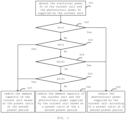
FIG. 1 is a flow diagram of a unit control method according to one embodiment of the present disclosure; -
FIG. 2 is a flow diagram of a unit control method according to another embodiment of the present disclosure; -
FIG. 3 is a flow diagram of a unit control method according to still another embodiment of the present disclosure; -
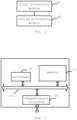
FIG. 4 is a schematic structural diagram of a unit control apparatus according to one embodiment of the present disclosure; -
FIG. 5 is a schematic structural diagram of a unit control apparatus according to another embodiment of the present disclosure; -
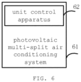
FIG. 6 is a schematic structural diagram of a photovoltaic multi-split air conditioning system according to one embodiment of the present disclosure. - It shall be understood that the various parts shown in the accompanying drawings are not drawn in sizes according to actual proportional relations. In addition, the same or similar reference numerals indicate the same or similar components.
- Various illustrative embodiments of the present disclosure will now be described in details with reference to the accompanying drawings. The descriptions of the illustrative embodiments are only illustrative, but shall not serve as limitations on the present disclosure and its application or utilization. The present disclosure can be implemented in many different forms and is not limited to the embodiments described herein. These embodiments are provided to make the present disclosure thorough and complete, and to fully express the scope of the present disclosure to those skilled in the art. It should be noted that unless otherwise illustrated, the relative arrangements of the components and steps, the components of the materials, and values set forth in these embodiments are to be construed as illustrative only and not as a limitation.
- Similar words such as "include" or "comprise" and the like used in the present disclosure mean that the elements preceding the word contain the elements listed after the word, and do not exclude the possibility of containing other elements.
- All terms (including technical or scientific terms) used in the present disclosure have the same meaning as those understood by one ordinary skilled in the art to which the present disclosure belongs, unless specifically defined otherwise. It shall be further understood that, the terms as defined in a common dictionary shall be interpreted as having meanings consistent with those in the context of the relevant technique, instead of being interpreted with an idealistic or extremely formalized meaning, unless it is explicitly defined here.
- Techniques, methods and devices that have already been known to ordinary skilled in the art may not be discussed here in details, but under suitable circumstances, the techniques, methods and devices shall be deemed as parts of the description.
- The inventors found that the output of the unit would be reduced under a condition that the actual operating load of the unit and the operating frequency of the compressor are reduced. This approach of ensuring the reliability of the unit by sacrificing the performance of the unit will reduce the user experience.
- Accordingly, the present disclosure provides a unit control solution, which can ensure the reliability of the unit without affecting the performance of the unit, thus improving the user experience.
-
FIG. 1 is a flow diagram of a unit control method according to one embodiment of the present disclosure. In some embodiments, the following unit control method is performed by a unit control apparatus. - In
step 101, a temperature of an inverter module of a current unit is detected at a first preset period. - In
step 102, it is determined whether the temperature of the inverter module is less than a first preset threshold. - In
step 103, a demand capacity of the current unit and a photovoltaic power supplied by the current unit is controlled not to be increased in a case where the temperature is not less than a first preset threshold. - For example, the demand capacity of the current unit and the photovoltaic power supplied by the current unit are controlled to remain unchanged, or at least one of the demand capacity of the current unit or the photovoltaic power supplied by the current unit is controlled to be reduced according to a preset ratio.
- In some embodiments, in a case where the temperature of the inverter module is less than the first preset threshold, routine control is performed on the unit. Since routine control of the unit is not the inventive point of the present disclosure, it is not described here.
- In the unit control method provided by the above embodiment of the present disclosure, in a case where the temperature of the inverter module of the current unit is not less than the preset threshold, the demand capacity of the current unit and the photovoltaic power supplied by the current unit are controlled not to be increased, thus ensuring the reliability of the unit without affecting the performance of the unit and effectively improving the user experience.
-
FIG. 2 is a flow diagram of a unit control method according to another embodiment of the present disclosure. In some embodiments, the following unit control method is performed by the unit control apparatus. - In
step 201, the temperature of the inverter module of the current unit is detected at the first preset period. - In
step 202, it is determined whether the temperature of the inverter module is less than a first preset threshold a. - If the temperature of the inverter module is less than the first preset threshold a, that is, the temperature T of the inverter module satisfies T<a,
step 203 is executed. If the temperature of the inverter module is not less than the first preset threshold a,step 204 is executed. - In
step 203, the routine control is performed on the current unit. - In
step 204, it is determined whether the temperature of the inverter module is less than a second preset threshold b, wherein the second preset threshold b is greater than the first preset threshold a. - If the temperature of the inverter module is less than the second preset threshold b, that is, the temperature T of the inverter module satisfies : a≤T< b, then step 205 is executed; if the temperature of the inverter module is not less than the second preset threshold,
step 206 is executed. - In
step 205, the demand capacity of the current unit and the photovoltaic power supplied by the current unit are controlled not to be increased. - For example, the demand capacity of the current unit and the photovoltaic power supplied by the current unit are controlled to remain unchanged.
- In some embodiments, in a case where there is the load increment in the multi-split system, the load increment is distributed to other units in an operating state except the current unit in a multi-split system. Therefore, the total demand capacity of the system is kept unchanged while controlling the temperature of the inverter module.
- In
step 206, it is determined whether the temperature of the inverter module is less than a third preset threshold c, wherein the third preset threshold c is greater than the second preset threshold b. - If the temperature of the inverter module is less than the third preset threshold c, that is, the temperature T of the inverter module satisfies : b≤T< c, then step 207 is executed; if the temperature of the inverter module is not less than the third preset threshold c, that is, the temperature T of the inverter module satisfies T>c,
step 208 is executed. - In
step 207, at least one of the demand capacity of the current unit or the photovoltaic power supplied by the current unit is reduced based on a preset ratio at the second preset period. - Step 207 will be illustrated by
FIG. 3 . - In
step 208, it is determined whether all units in the multi-split system are in the operating state. - If all units in the multi-split system are in the operating state, step 209 will be executed; if part units in the multi-split system are in the standby state,
step 210 is executed. - In
step 209, the current unit is shut down, and the current unit is prohibited from starting up within a preset time range. - In some embodiments, the demand capacity of the current unit before shutdown is distributed to the units in the operating state in the multi-split system according to the unit capacity ratio, thus ensuring that the total demand capacity of the system remains unchanged.
- In
step 210, the current unit is shut down, and the current unit is prohibited from starting up within a preset time range. - In
step 211, one unit among units in the standby state is selected as the target unit, the target unit is started up to replace the current unit, and the total demand capacity is redistributed in the multi-split system after the target unit is started up. -
FIG. 3 is a flow diagram of a unit control method according to still another embodiment of the present disclosure. In some embodiments, the following unit control method is executed by the unit control apparatus. In some embodiments, theabove step 208 is as follows: - In
step 301, the electrical power P1 of the current unit and the photovoltaic power P2 supplied by the current unit are detected. - In
step 302, it is determined whether the electrical power P1 of the current unit is 0. - If P1=0,
step 308 is executed; if P1≠0,step 303 is executed. - It should be noted that if P1=0, it indicates that the current unit is in a pure photovoltaic electricity generation mode.
- In
step 303, it is determined whether the photovoltaic power P2 supplied by the current unit is 0. - If P2=0,
step 307 is executed; ifP2# 0,step 304 is executed. - It should be noted that if P2=0, it indicates that the current unit is in a pure air conditioning mode, and the electric energy used is completely provided by an AC power grid.
- In
step 304, it is determined whether the photovoltaic power P2 supplied by the current unit is greater than the electrical power P1 of the current unit. - If P2>P1,
step 308 is executed; otherwise,step 305 is executed. - It should be noted that if P2>P1, it indicates that the current unit is in an electricity generation mode of the photovoltaic air conditioning system, that is, the photovoltaic power supply not only supplies power to the air conditioning unit, but also provides power for the AC power grid or charges the energy storage equipment.
- In
step 305, it is determined whether the photovoltaic power P2 supplied by the current unit is less than the electrical power P1 of the current unit. - If P2<P1,
step 307 is executed; if P2=P1,step 306 is executed. - It should be noted that if P2<P1, it indicates that the current unit is in the electricity consumption mode of the photovoltaic air conditioning system, that is, photovoltaic power supply and AC power supply simultaneously supply power to the air conditioning unit.
- If P2=P1, it indicates that the current unit is in the photovoltaic air conditioning mode, that is, the photovoltaic power supply is just used to supply power to the air conditioning unit, and there is no need to use AC power supply.
- In
step 306, the demand capacity of the current unit and the photovoltaic power supplied by the current unit are reduced based on a preset ratio at the a second preset period. - In some embodiments, the decrement of the demand capacity of the current unit is distributed to other units in the operating state except the current unit in the multi-split system according to the unit capacity ratio, so as to ensure that the total demand capacity of the system remains unchanged.
- In
step 307, the demand capacity of the current unit is reduced based on the preset ratio at the second preset period. - In some embodiments, the decrement of the demand capacity of the current unit is distributed to other units in the operating state except the current unit in the multi-split system according to the unit capacity ratio, so as to ensure that the total demand capacity of the system remains unchanged.
- In
step 308, the photovoltaic power supplied by the current unit is reduced according to a preset ratio at a second preset period, so as to meet the needs of users while ensuring the reliability of the unit. -
FIG. 4 is a schematic structural diagram of a unit control apparatus according to one embodiment of the present disclosure. As shown inFIG. 4 , the unit control apparatus includes afirst processing module 41 and asecond processing module 42. - The
first processing module 41 is configured to detect a temperature of an inverter module of a current unit at a first preset period. - The
second processing module 42 is configured to determine whether the temperature is less than a first preset threshold, and control a demand capacity of the current unit and a photovoltaic power supplied by the current unit not to be increased in a case where the temperature is not less than a first preset threshold. - For example, the demand capacity of the current unit and the photovoltaic power supplied by the current unit are controlled to remain unchanged, or at least one of the demand capacity of the current unit or the photovoltaic power supplied by the current unit is controlled to reduce according to a preset ratio.
- In the unit control apparatus provided by the above embodiment of the present disclosure, when the temperature of the inverter module of the current unit is not less than the preset threshold, the demand capacity of the current unit and the photovoltaic power supplied by the current unit are controlled not to increase, so as to ensure the reliability of the unit without affecting the performance of the unit, and effectively improve the user experience.
- In some embodiments, the
second processing module 42 is configured to determine whether the temperature is less than a second preset threshold, wherein the second preset threshold is greater than the first preset threshold, control the demand capacity of the current unit and the photovoltaic power supplied by the current unit not to be increased in a case where the temperature is less than the second preset threshold. For example, the demand capacity of the current unit and the photovoltaic power supplied by the current unit are controlled to remain unchanged, and distribute a load increment to other units in an operating state except the current unit in a multi-split system in a case where there is the load increment in the multi-split system. - In some embodiments, the
second processing module 42 is configured to whether the temperature is less than a third preset threshold in a case where the temperature is not less than the second preset threshold, wherein the third preset threshold is greater than the second preset threshold; and reduce at least one of the demand capacity of the current unit or the photovoltaic power supplied by the current unit based on a preset ratio at a second preset period in a case where the temperature is less than the third preset threshold. - In some embodiments, the
second processing module 42 is configured to determine whether a electrical power of the current unit is 0, and reduce the photovoltaic power supplied by the current unit based on the preset ratio at the second preset period in a case where the electrical power of the current unit is 0. - In some embodiments, the
second processing module 42 is configured to determine whether the photovoltaic power supplied by the current unit is 0 in a case where the electrical power of the current unit is not 0, and reduce the demand capacity of the current unit based on a preset ratio at the second preset period in a case where the photovoltaic power supplied by the current unit is 0. - In some embodiments, the
second processing module 42 is configured to determine whether the photovoltaic power supplied by the current unit is greater than the electrical power of the current unit in a case where the photovoltaic power supplied by the current unit is not 0, and reduce the photovoltaic power supplied by the current unit based on a preset ratio at the second preset period in a case where the photovoltaic power supplied by the current unit is greater than the electrical power of the current unit. - In some embodiments, the
second processing module 42 is configured to determine whether the photovoltaic power supplied by the current unit is less than the electrical power of the current unit in a case where the photovoltaic power supplied by the current unit is not greater than the electrical power of the current unit, and reduce the demand capacity of the current unit based on a preset ratio at the second preset period in a case where the photovoltaic power supplied by the current unit is less than the electrical power of the current unit. - In some embodiments, the
second processing module 42 is configured to reduce the demand capacity of the current unit and the photovoltaic power supplied by the current unit based on a preset ratio at the second preset period in a case where the photovoltaic power supplied by the current unit is equal to the electrical power of the current unit. - In some embodiments, the
second processing module 42 is configured to distribute a decrement of the demand capacity of the current unit to other units in the operating state except the current unit in the multi-split system based on a unit capacity ratio. - In some embodiments, the
second processing module 42 is configured to determine whether all units in the multi-split system are in the operating state in a case where the temperature is not less than the third preset threshold, and shut down the current unit, and prohibit the current unit from starting up within a preset time range in a case where the all units in the multi-split system are in the operating state. - In some embodiments, the
second processing module 42 is configured to distribute a demand capacity of the current unit before shutdown to units in the operating state in the multi-split system based on the unit capacity ratio. - In some embodiments, the
second processing module 42 is configured to shut down the current unit, and prohibiting the current unit from starting up within a preset time range in a case where part units in the multi-split system are in a standby state, select a unit among units in the standby state as a target unit, and start up the target unit to replace the current unit, and redistribute a total demand capacity in the multi-split system after the target unit is started up. -
FIG. 5 is a schematic structural diagram of a unit control apparatus according to another embodiment of the present disclosure. As shown inFIG. 5 , the unit control apparatus includes amemory 51 and aprocessor 52. - The
memory 51 is used for storing instructions, and theprocessor 52 is coupled to thememory 51, and theprocessor 52 is configured to implement the method according to any of the embodiments inFIGS. 1 to 3 based on the instructions stored in the memory. - As shown in
FIG. 5 , the unit control apparatus also includes acommunication interface 53 for information interaction with other devices. At the same time, the unit control apparatus also includes abus 54 through which theprocessor 52, thecommunication interface 53 and thememory 51 communicate with each other. - The
memory 51 may include a high-speed RAM memory, and may also include a non-volatile memory, such as at least one disk memory. Thememory 51 may also be a memory array. Thememory 51 may also be partitioned, and the blocks may be combined into a virtual volume according to certain rules. - Further, the
processor 52 may be a central processing unit CPU, or may be an application specific integrated circuit ASIC, or one or more integrated circuits configured to implement the embodiments of the present disclosure. - The present disclosure also relates to a computer-readable storage medium, wherein the computer-readable storage medium stores computer instructions, which, when executed by a processor, implement the method according to any one of the embodiments in
FIGS. 1 to 3 . -
FIG. 6 is a schematic structural diagram of a photovoltaic multi-split air conditioning system according to an embodiment of the present disclosure. As shown inFIG. 6 , a photovoltaic multi-splitair conditioning system 61 includes aunit control apparatus 62. Theunit control apparatus 62 is the unit control apparatus according to any embodiment inFIG. 4 or FIG. 5 . - In some embodiments, the functional unit modules described above can be implemented as a general processor, a Programmable Logic Controller (PLC), a Digital Signal Processor (DSP), application specific integrated circuit (ASIC), field-programmable gate array (FPGA) or other programmable logic devices, discrete gate or transistor logic devices, discrete hardware components or any suitable combination thereof.
- So far, the embodiments of the present disclosure have been described in detail. In order to avoid shielding of the concept of the present disclosure, some details commonly known in the art are not described. Based on the above description, those skilled in the art can fully understand how to carry out the technical solutions disclosed here.
- While some specific embodiments of the present disclosure have been described in detail by way of examples, those skilled in the art should understand that the above examples are for illustrative purposes only and are not intended to limit the scope of the disclosure. Those skilled in the art will appreciate that the above embodiments may be modified or an equivalent substitution may be performed on some of the technical features without departing from the scope and spirit of the present disclosure. The scope of the present disclosure is defined by the appended claims.
Claims (27)
- A unit control method, comprising:detecting a temperature of an inverter module of a current unit at a first preset period; andcontrolling a demand capacity of the current unit and a photovoltaic power supplied by the current unit not to be increased in a case where the temperature is not less than a first preset threshold.
- The unit control method according to claim 1, wherein the controlling a demand capacity of the current unit and a photovoltaic power supplied by the current unit not to be increased comprises:determining whether the temperature is less than a second preset threshold, wherein the second preset threshold is greater than the first preset threshold;controlling the demand capacity of the current unit and the photovoltaic power supplied by the current unit not to be increased in a case where the temperature is less than the second preset threshold; anddistributing a load increment to other units in an operating state except the current unit in a multi-split system in a case where there is the load increment in the multi-split system.
- The unit control method according to claim 2, further comprising:determining whether the temperature is less than a third preset threshold in a case where the temperature is not less than the second preset threshold, wherein the third preset threshold is greater than the second preset threshold; andreducing at least one of the demand capacity of the current unit or the photovoltaic power supplied by the current unit based on a preset ratio at a second preset period in a case where the temperature is less than the third preset threshold.
- The unit control method according to claim 3, wherein the reducing at least one of the demand capacity of the current unit or the photovoltaic power supplied by the current unit based on a preset ratio at a second preset period comprises:determining whether a electrical power of the current unit is 0; andreducing the photovoltaic power supplied by the current unit based on the preset ratio at the second preset period in a case where the electrical power of the current unit is 0.
- The unit control method according to claim 4, further comprising:determining whether the photovoltaic power supplied by the current unit is 0 in a case where the electrical power of the current unit is not 0; andreducing the demand capacity of the current unit based on a preset ratio at the second preset period in a case where the photovoltaic power supplied by the current unit is 0.
- The unit control method according to claim 5, further comprising:determining whether the photovoltaic power supplied by the current unit is greater than the electrical power of the current unit in a case where the photovoltaic power supplied by the current unit is not 0; andreducing the photovoltaic power supplied by the current unit based on a preset ratio at the second preset period in a case where the photovoltaic power supplied by the current unit is greater than the electrical power of the current unit.
- The unit control method according to claim 6, further comprising:determining whether the photovoltaic power supplied by the current unit is less than the electrical power of the current unit in a case where the photovoltaic power supplied by the current unit is not greater than the electrical power of the current unit; andreducing the demand capacity of the current unit based on a preset ratio at the second preset period in a case where the photovoltaic power supplied by the current unit is less than the electrical power of the current unit.
- The unit control method according to claim 7, further comprising:
reducing the demand capacity of the current unit and the photovoltaic power supplied by the current unit based on a preset ratio at the second preset period in a case where the photovoltaic power supplied by the current unit is equal to the electrical power of the current unit. - The unit control method according to claim 5, 7 or 8, further comprising:
distributing a decrement of the demand capacity of the current unit to other units in the operating state except the current unit in the multi-split system based on a unit capacity ratio. - The unit control method according to claim 3, further comprising:determining whether all units in the multi-split system are in the operating state in a case where the temperature is not less than the third preset threshold; andshutting down the current unit, and prohibiting the current unit from starting up within a preset time range in a case where the all units in the multi-split system are in the operating state.
- The unit control method according to claim 10, further comprising:
distributing a demand capacity of the current unit before shutdown to units in the operating state in the multi-split system based on the unit capacity ratio. - The unit control method according to claim 10, further comprising:shutting down the current unit, and prohibiting the current unit from starting up within a preset time range in a case where part units in the multi-split system are in a standby state;selecting a unit among units in the standby state as a target unit; andstarting up the target unit to replace the current unit, and redistributing a total demand capacity in the multi-split system after the target unit is started up.
- A unit control apparatus, comprising:a first processing module configured to detect a temperature of an inverter module of a current unit at a first preset period; anda second processing module configured to control a demand capacity of the current unit and a photovoltaic power supplied by the current unit not to be increased in a case where the temperature is not less than a first preset threshold.
- The unit control apparatus according to claim 13, wherein
the second processing module is configured to determine whether the temperature is less than a second preset threshold, wherein the second preset threshold is greater than the first preset threshold, control the demand capacity of the current unit and the photovoltaic power supplied by the current unit not to be increased in a case where the temperature is less than the second preset threshold, and distribute a load increment to other units in an operating state except the current unit in a multi-split system in a case where there is the load increment in the multi-split system. - The unit control apparatus according to claim 14, wherein
the second processing module is configured to determine whether the temperature is less than a third preset threshold in a case where the temperature is not less than the second preset threshold, wherein the third preset threshold is greater than the second preset threshold; and reduce at least one of the demand capacity of the current unit or the photovoltaic power supplied by the current unit based on a preset ratio at a second preset period in a case where the temperature is less than the third preset threshold. - The unit control apparatus according to claim 15, wherein
the second processing module is configured to determine whether a electrical power of the current unit is 0, and reduce the photovoltaic power supplied by the current unit based on the preset ratio at the second preset period in a case where the electrical power of the current unit is 0. - The unit control apparatus according to claim 16, wherein
the second processing module is configured to determine whether the photovoltaic power supplied by the current unit is 0 in a case where the electrical power of the current unit is not 0, and reduce the demand capacity of the current unit based on a preset ratio at the second preset period in a case where the photovoltaic power supplied by the current unit is 0. - The unit control apparatus according to claim 17, wherein
the second processing module is configured to determine whether the photovoltaic power supplied by the current unit is greater than the electrical power of the current unit in a case where the photovoltaic power supplied by the current unit is not 0, and reduce the photovoltaic power supplied by the current unit based on a preset ratio at the second preset period in a case where the photovoltaic power supplied by the current unit is greater than the electrical power of the current unit. - The unit control apparatus according to claim 18, wherein
the second processing module is configured to determine whether the photovoltaic power supplied by the current unit is less than the electrical power of the current unit in a case where the photovoltaic power supplied by the current unit is not greater than the electrical power of the current unit, and reduce the demand capacity of the current unit based on a preset ratio at the second preset period in a case where the photovoltaic power supplied by the current unit is less than the electrical power of the current unit. - The unit control apparatus according to claim 19, wherein
the second processing module is configured to reduce the demand capacity of the current unit and the photovoltaic power supplied by the current unit based on a preset ratio at the second preset period in a case where the photovoltaic power supplied by the current unit is equal to the electrical power of the current unit. - The unit control apparatus according to claim 17, 19 or 20, wherein
the second processing module is configured to distribute a decrement of the demand capacity of the current unit to other units in the operating state except the current unit in the multi-split system based on a unit capacity ratio. - The unit control apparatus according to claim 15, wherein
the second processing module is configured to determine whether all units in the multi-split system are in the operating state in a case where the temperature is not less than the third preset threshold, and shut down the current unit, and prohibit the current unit from starting up within a preset time range in a case where the all units in the multi-split system are in the operating state. - The unit control apparatus according to claim 22, wherein
the second processing module is configured to distribute a demand capacity of the current unit before shutdown to units in the operating state in the multi-split system based on the unit capacity ratio. - The unit control apparatus according to claim 22, wherein
the second processing module is configured to shut down the current unit, and prohibiting the current unit from starting up within a preset time range in a case where part units in the multi-split system are in a standby state, select a unit among units in the standby state as a target unit, and start up the target unit to replace the current unit, and redistribute a total demand capacity in the multi-split system after the target unit is started up. - A unit control apparatus, comprising:a processor; anda memory coupled to the processor, storing program instructions which, when executed by the processor, cause the processor to implement the unit control method according to any one of claims 1 to 12.
- A photovoltaic multi-split air conditioning system, comprising the unit control apparatus according to any one of claims 13 to 25.
- A computer-readable storage medium, wherein the computer-readable storage medium stores computer instructions which, when executed by a processor, implement the method according to any one of claims 1 to 12.
Applications Claiming Priority (2)
| Application Number | Priority Date | Filing Date | Title |
|---|---|---|---|
| CN202210078432.9A CN114413447B (en) | 2022-01-24 | 2022-01-24 | Unit control method and device and photovoltaic multi-split air conditioning system |
| PCT/CN2022/124741 WO2023138113A1 (en) | 2022-01-24 | 2022-10-12 | Method and apparatus for unit control and photovoltaic multi-unit air conditioning system |
Publications (2)
| Publication Number | Publication Date |
|---|---|
| EP4435342A1 true EP4435342A1 (en) | 2024-09-25 |
| EP4435342A4 EP4435342A4 (en) | 2025-03-12 |
Family
ID=81278323
Family Applications (1)
| Application Number | Title | Priority Date | Filing Date |
|---|---|---|---|
| EP22921540.5A Pending EP4435342A4 (en) | 2022-01-24 | 2022-10-12 | Method and apparatus for unit control and photovoltaic multi-unit air conditioning system |
Country Status (6)
| Country | Link |
|---|---|
| US (1) | US12607370B2 (en) |
| EP (1) | EP4435342A4 (en) |
| CN (1) | CN114413447B (en) |
| AU (1) | AU2022435875B2 (en) |
| CA (1) | CA3241222A1 (en) |
| WO (1) | WO2023138113A1 (en) |
Families Citing this family (2)
| Publication number | Priority date | Publication date | Assignee | Title |
|---|---|---|---|---|
| CN114413447B (en) * | 2022-01-24 | 2023-05-02 | 珠海格力电器股份有限公司 | Unit control method and device and photovoltaic multi-split air conditioning system |
| CN116358122B (en) * | 2023-04-13 | 2025-11-18 | 珠海格力电器股份有限公司 | Fan control methods, devices, systems and storage media |
Family Cites Families (17)
| Publication number | Priority date | Publication date | Assignee | Title |
|---|---|---|---|---|
| US8243446B2 (en) * | 2010-03-11 | 2012-08-14 | First Solar, Inc. | Photovoltaic inverter |
| CN202470298U (en) | 2011-12-30 | 2012-10-03 | 广州泓淮电子科技有限公司 | Controlling device for air conditioners working in turn |
| CN203787973U (en) | 2014-03-05 | 2014-08-20 | 深圳市长昊机电有限公司 | Photovoltaic power generation control system |
| CN104104311B (en) * | 2014-08-08 | 2017-04-19 | 阳光电源股份有限公司 | Photovoltaic power generation control system |
| US10309678B2 (en) | 2014-11-07 | 2019-06-04 | Daikin Industries, Ltd. | Air conditioning system |
| CN107388661B (en) | 2017-07-27 | 2020-07-28 | 广东美的制冷设备有限公司 | Solar air conditioning system and its power control method and device |
| CN107528293A (en) * | 2017-07-28 | 2017-12-29 | 珠海格力电器股份有限公司 | Unit fault processing method and device |
| CN109888827B (en) | 2019-03-13 | 2020-11-10 | 阳光电源股份有限公司 | Photovoltaic grid-connected inverter power limiting method and device, controller and inverter |
| CN110567139B (en) * | 2019-08-30 | 2021-02-26 | 珠海格力电器股份有限公司 | Frequency limiting and frequency reducing control method and device for photovoltaic air conditioner and photovoltaic air conditioner |
| CN111174369B (en) * | 2019-12-30 | 2021-04-20 | 珠海格力电器股份有限公司 | Control method of photovoltaic direct-drive variable frequency air conditioner, computer readable storage medium and air conditioner |
| CN111174389A (en) | 2020-01-08 | 2020-05-19 | 珠海格力电器股份有限公司 | Distributed power supply air conditioner power control method and air conditioner system |
| CN112467966B (en) * | 2020-11-18 | 2022-05-06 | 江苏为恒智能科技有限公司 | Over-temperature and load-reducing device and method for optical-storage integrated inverter |
| CN214275936U (en) * | 2020-12-18 | 2021-09-24 | 珠海格力电器股份有限公司 | Multi-split air conditioner |
| CN113007872B (en) * | 2021-03-19 | 2022-07-01 | 青岛海信日立空调系统有限公司 | Multi-split air conditioning system |
| CN113108442B (en) * | 2021-04-21 | 2022-05-06 | 珠海格力电器股份有限公司 | Capacity allocation method and apparatus, multi-split air conditioner, and storage medium |
| CN113489429A (en) | 2021-05-31 | 2021-10-08 | 上海航天电源技术有限责任公司 | Power control method and system of photovoltaic energy storage system |
| CN114413447B (en) | 2022-01-24 | 2023-05-02 | 珠海格力电器股份有限公司 | Unit control method and device and photovoltaic multi-split air conditioning system |
-
2022
- 2022-01-24 CN CN202210078432.9A patent/CN114413447B/en active Active
- 2022-10-12 WO PCT/CN2022/124741 patent/WO2023138113A1/en not_active Ceased
- 2022-10-12 US US18/720,779 patent/US12607370B2/en active Active
- 2022-10-12 EP EP22921540.5A patent/EP4435342A4/en active Pending
- 2022-10-12 AU AU2022435875A patent/AU2022435875B2/en active Active
- 2022-10-12 CA CA3241222A patent/CA3241222A1/en active Pending
Also Published As
| Publication number | Publication date |
|---|---|
| CN114413447B (en) | 2023-05-02 |
| WO2023138113A1 (en) | 2023-07-27 |
| CA3241222A1 (en) | 2023-07-27 |
| US20250060117A1 (en) | 2025-02-20 |
| CN114413447A (en) | 2022-04-29 |
| US12607370B2 (en) | 2026-04-21 |
| EP4435342A4 (en) | 2025-03-12 |
| AU2022435875A1 (en) | 2024-07-04 |
| AU2022435875B2 (en) | 2026-01-22 |
Similar Documents
| Publication | Publication Date | Title |
|---|---|---|
| EP4435342A1 (en) | Method and apparatus for unit control and photovoltaic multi-unit air conditioning system | |
| CN102687094B (en) | Processing method and appliance for multi-power supply | |
| EP3800763B1 (en) | Multi-mode uninterruptible power supply control method, control apparatus and control terminal | |
| CN106030452A (en) | Standby Power Management for Computing Systems | |
| CN109236622B (en) | Compressor frequency control method and device and air conditioner | |
| US10534420B2 (en) | Electronic devices, electronic systems, and control methods therefor | |
| CN117613322A (en) | Control method and device of fuel cell, vehicle and storage medium | |
| JP2022061672A (en) | Controller | |
| CN106339064A (en) | Method and device for rebooting | |
| US20110154069A1 (en) | Dynamic power state determination | |
| US12483062B2 (en) | Uninterruptible power supply, uninterruptible power supply control method, related apparatus, and system | |
| WO2026011471A1 (en) | Device control method, inverter and computer-readable storage medium | |
| CN111200171A (en) | System efficiency control device and method | |
| CN118611189A (en) | Method, device, equipment and medium for controlling active power increase of grid-connected converter | |
| US12613565B2 (en) | Controlling a power consumption of circuitry | |
| CN118494236A (en) | Charging pile heat dissipation control method and device, charging pile and medium | |
| US9575550B1 (en) | Method for coordinating operation of an off-grid, hybrid power system and an information technology system | |
| CN104679133B (en) | Computer device | |
| EP4510420A2 (en) | Power management system and power management method | |
| CN113067403A (en) | Method and device for processing shared mobile power supply service | |
| CN115118004B (en) | UPS control method and control terminal | |
| TWI854780B (en) | Power management system and power management method | |
| CN114706467B (en) | Energy-saving processing method for multiple DRAM systems | |
| EP4734361A1 (en) | Detection method and apparatus for inverter system and inverter system | |
| CN121268800B (en) | Energy management method, electronic device and vehicle |
Legal Events
| Date | Code | Title | Description |
|---|---|---|---|
| STAA | Information on the status of an ep patent application or granted ep patent |
Free format text: STATUS: THE INTERNATIONAL PUBLICATION HAS BEEN MADE |
|
| PUAI | Public reference made under article 153(3) epc to a published international application that has entered the european phase |
Free format text: ORIGINAL CODE: 0009012 |
|
| STAA | Information on the status of an ep patent application or granted ep patent |
Free format text: STATUS: REQUEST FOR EXAMINATION WAS MADE |
|
| 17P | Request for examination filed |
Effective date: 20240618 |
|
| AK | Designated contracting states |
Kind code of ref document: A1 Designated state(s): AL AT BE BG CH CY CZ DE DK EE ES FI FR GB GR HR HU IE IS IT LI LT LU LV MC ME MK MT NL NO PL PT RO RS SE SI SK SM TR |
|
| A4 | Supplementary search report drawn up and despatched |
Effective date: 20250207 |
|
| RIC1 | Information provided on ipc code assigned before grant |
Ipc: H02J 3/46 20060101ALI20250203BHEP Ipc: H02J 3/14 20060101ALI20250203BHEP Ipc: F24F 11/88 20180101ALI20250203BHEP Ipc: H02J 7/35 20060101ALI20250203BHEP Ipc: H02M 1/32 20070101ALI20250203BHEP Ipc: H02J 3/38 20060101ALI20250203BHEP Ipc: G05D 23/00 20060101ALI20250203BHEP Ipc: F24F 5/00 20060101ALI20250203BHEP Ipc: H02H 7/00 20060101ALI20250203BHEP Ipc: F24F 11/86 20180101ALI20250203BHEP Ipc: F24F 11/89 20180101AFI20250203BHEP Ipc: G05F 1/67 20060101ALI20250203BHEP |
|
| DAV | Request for validation of the european patent (deleted) | ||
| DAX | Request for extension of the european patent (deleted) |