EP4435341A1 - Air conditioner - Google Patents
Air conditioner Download PDFInfo
- Publication number
- EP4435341A1 EP4435341A1 EP22895310.5A EP22895310A EP4435341A1 EP 4435341 A1 EP4435341 A1 EP 4435341A1 EP 22895310 A EP22895310 A EP 22895310A EP 4435341 A1 EP4435341 A1 EP 4435341A1
- Authority
- EP
- European Patent Office
- Prior art keywords
- compressor
- condition
- temperature
- indoor
- difference
- Prior art date
- Legal status (The legal status is an assumption and is not a legal conclusion. Google has not performed a legal analysis and makes no representation as to the accuracy of the status listed.)
- Pending
Links
Images



Classifications
-
- F—MECHANICAL ENGINEERING; LIGHTING; HEATING; WEAPONS; BLASTING
- F24—HEATING; RANGES; VENTILATING
- F24F—AIR-CONDITIONING; AIR-HUMIDIFICATION; VENTILATION; USE OF AIR CURRENTS FOR SCREENING
- F24F11/00—Control or safety arrangements
- F24F11/70—Control systems characterised by their outputs; Constructional details thereof
- F24F11/80—Control systems characterised by their outputs; Constructional details thereof for controlling the temperature of the supplied air
- F24F11/86—Control systems characterised by their outputs; Constructional details thereof for controlling the temperature of the supplied air by controlling compressors within refrigeration or heat pump circuits
-
- F—MECHANICAL ENGINEERING; LIGHTING; HEATING; WEAPONS; BLASTING
- F24—HEATING; RANGES; VENTILATING
- F24F—AIR-CONDITIONING; AIR-HUMIDIFICATION; VENTILATION; USE OF AIR CURRENTS FOR SCREENING
- F24F11/00—Control or safety arrangements
- F24F11/50—Control or safety arrangements characterised by user interfaces or communication
- F24F11/61—Control or safety arrangements characterised by user interfaces or communication using timers
-
- F—MECHANICAL ENGINEERING; LIGHTING; HEATING; WEAPONS; BLASTING
- F24—HEATING; RANGES; VENTILATING
- F24F—AIR-CONDITIONING; AIR-HUMIDIFICATION; VENTILATION; USE OF AIR CURRENTS FOR SCREENING
- F24F11/00—Control or safety arrangements
- F24F11/62—Control or safety arrangements characterised by the type of control or by internal processing, e.g. using fuzzy logic, adaptive control or estimation of values
-
- F—MECHANICAL ENGINEERING; LIGHTING; HEATING; WEAPONS; BLASTING
- F25—REFRIGERATION OR COOLING; COMBINED HEATING AND REFRIGERATION SYSTEMS; HEAT PUMP SYSTEMS; MANUFACTURE OR STORAGE OF ICE; LIQUEFACTION SOLIDIFICATION OF GASES
- F25B—REFRIGERATION MACHINES, PLANTS OR SYSTEMS; COMBINED HEATING AND REFRIGERATION SYSTEMS; HEAT PUMP SYSTEMS
- F25B49/00—Arrangement or mounting of control or safety devices
- F25B49/02—Arrangement or mounting of control or safety devices for compression type machines, plants or systems
- F25B49/022—Compressor control arrangements
-
- F—MECHANICAL ENGINEERING; LIGHTING; HEATING; WEAPONS; BLASTING
- F24—HEATING; RANGES; VENTILATING
- F24F—AIR-CONDITIONING; AIR-HUMIDIFICATION; VENTILATION; USE OF AIR CURRENTS FOR SCREENING
- F24F2110/00—Control inputs relating to air properties
- F24F2110/10—Temperature
-
- F—MECHANICAL ENGINEERING; LIGHTING; HEATING; WEAPONS; BLASTING
- F25—REFRIGERATION OR COOLING; COMBINED HEATING AND REFRIGERATION SYSTEMS; HEAT PUMP SYSTEMS; MANUFACTURE OR STORAGE OF ICE; LIQUEFACTION SOLIDIFICATION OF GASES
- F25B—REFRIGERATION MACHINES, PLANTS OR SYSTEMS; COMBINED HEATING AND REFRIGERATION SYSTEMS; HEAT PUMP SYSTEMS
- F25B2600/00—Control issues
- F25B2600/01—Timing
-
- F—MECHANICAL ENGINEERING; LIGHTING; HEATING; WEAPONS; BLASTING
- F25—REFRIGERATION OR COOLING; COMBINED HEATING AND REFRIGERATION SYSTEMS; HEAT PUMP SYSTEMS; MANUFACTURE OR STORAGE OF ICE; LIQUEFACTION SOLIDIFICATION OF GASES
- F25B—REFRIGERATION MACHINES, PLANTS OR SYSTEMS; COMBINED HEATING AND REFRIGERATION SYSTEMS; HEAT PUMP SYSTEMS
- F25B2600/00—Control issues
- F25B2600/02—Compressor control
- F25B2600/021—Inverters therefor
-
- F—MECHANICAL ENGINEERING; LIGHTING; HEATING; WEAPONS; BLASTING
- F25—REFRIGERATION OR COOLING; COMBINED HEATING AND REFRIGERATION SYSTEMS; HEAT PUMP SYSTEMS; MANUFACTURE OR STORAGE OF ICE; LIQUEFACTION SOLIDIFICATION OF GASES
- F25B—REFRIGERATION MACHINES, PLANTS OR SYSTEMS; COMBINED HEATING AND REFRIGERATION SYSTEMS; HEAT PUMP SYSTEMS
- F25B2600/00—Control issues
- F25B2600/02—Compressor control
- F25B2600/025—Compressor control by controlling speed
- F25B2600/0253—Compressor control by controlling speed with variable speed
-
- F—MECHANICAL ENGINEERING; LIGHTING; HEATING; WEAPONS; BLASTING
- F25—REFRIGERATION OR COOLING; COMBINED HEATING AND REFRIGERATION SYSTEMS; HEAT PUMP SYSTEMS; MANUFACTURE OR STORAGE OF ICE; LIQUEFACTION SOLIDIFICATION OF GASES
- F25B—REFRIGERATION MACHINES, PLANTS OR SYSTEMS; COMBINED HEATING AND REFRIGERATION SYSTEMS; HEAT PUMP SYSTEMS
- F25B2600/00—Control issues
- F25B2600/23—Time delays
-
- F—MECHANICAL ENGINEERING; LIGHTING; HEATING; WEAPONS; BLASTING
- F25—REFRIGERATION OR COOLING; COMBINED HEATING AND REFRIGERATION SYSTEMS; HEAT PUMP SYSTEMS; MANUFACTURE OR STORAGE OF ICE; LIQUEFACTION SOLIDIFICATION OF GASES
- F25B—REFRIGERATION MACHINES, PLANTS OR SYSTEMS; COMBINED HEATING AND REFRIGERATION SYSTEMS; HEAT PUMP SYSTEMS
- F25B2700/00—Sensing or detecting of parameters; Sensors therefor
- F25B2700/21—Temperatures
- F25B2700/2104—Temperatures of an indoor room or compartment
Definitions
- the present disclosure relates to an air conditioner.
- an air conditioner that performs air conditioning by a refrigerant circulating in a refrigerant circuit.
- the refrigerant circuit includes a heat source-side heat exchanger, a usage-side heat exchanger, and a compressor for circulating the refrigerant.
- There is also known a technique of temporarily stopping a compressor when an indoor temperature reaches a predetermined target temperature and operating the compressor again when the indoor temperature deviates from the predetermined target temperature see, for example, Patent Literature 1).
- PATENT LITERATURE 1 Japanese Patent No. 6072424
- control is performed in which an operating frequency of the compressor is increased, maintained, or decreased in accordance with a temperature difference between the indoor temperature and the target temperature and a gradient of the temperature difference (a change amount of the temperature difference per unit time) to bring the indoor temperature close to the target temperature. For example, under a situation where an air conditioning load is low and the temperature difference is small, control is performed such that a descending gradient of the temperature difference becomes gentle by lowering the operating frequency of the compressor. When the temperature difference between the indoor temperature and the target temperature falls below a predetermined threshold, the compressor is temporarily stopped to stop air conditioning.
- An object of the present disclosure is to suppress a start/stop frequency of a compressor.
- FIG. 1 is a schematic refrigerant circuit diagram of an air conditioner according to a first embodiment of the present disclosure.
- FIG. 2 is a block diagram of the air conditioner.
- the air conditioner 1 adjusts a temperature of air in an indoor space as an air conditioning target space to a predetermined target temperature.
- the air conditioner 1 according to the present embodiment cools and heats the indoor space.
- the air conditioner 1 includes an outdoor unit 2, an indoor unit 3, and a refrigerant circuit 4 that circulates a refrigerant between the outdoor unit 2 and the indoor unit 3.
- the refrigerant circuit 4 includes a compressor 12, a four-way switching valve 17, an outdoor heat exchanger (heat source heat exchanger) 14, a first expansion valve 13, a receiver 25, a second expansion valve 15, a liquid shutoff valve 19, an indoor heat exchanger (utilization heat exchanger) 11, a gas shutoff valve 20, an accumulator 16, refrigerant pipes 10L and 10G that connect the above components, and the like.
- the indoor unit 3 includes the indoor heat exchanger 11 constituting the refrigerant circuit 4.
- the indoor heat exchanger 11 is of a cross-fin tube type or a microchannel type, and is used for heat exchange with indoor air.
- the indoor unit 3 further includes an indoor fan 21, an indoor controller 22, an indoor temperature sensor 23, a refrigerant temperature sensor 27, and a remote controller 24.
- the indoor fan 21 is configured to take indoor air into the indoor unit 3, cause heat exchange between the taken air and the refrigerant flowing through the indoor heat exchanger 11, and blow the air to the indoor space.
- the indoor fan 21 includes a motor having an operating frequency adjustable by inverter control.
- the indoor controller 22 controls an operation of the indoor fan 21.
- the indoor controller 22 is constituted by a microcomputer including a calculation unit such as a CPU and a storage such as a RAM or a ROM.
- the indoor controller 22 may include an integrated circuit such as an FPGA or an ASIC.
- the indoor temperature sensor 23 measures indoor temperature. Information on the indoor temperature detected by the indoor temperature sensor 23 is transmitted to the indoor controller 22. The indoor controller 22 transmits the received information on the indoor temperature to an outdoor controller 33 described later.
- the refrigerant temperature sensor 27 detects a temperature of a refrigerant (gas-liquid two-phase refrigerant) flowing in the indoor heat exchanger 11.
- a refrigerant gas-liquid two-phase refrigerant
- the indoor heat exchanger 11 is an evaporator
- the temperature detected by the refrigerant temperature sensor 27 is an evaporation temperature of the refrigerant.
- the indoor heat exchanger 11 is a condenser
- the temperature detected by the refrigerant temperature sensor 27 is a condensation temperature of the refrigerant.
- Information on the temperature of the refrigerant detected by the refrigerant temperature sensor 27 is transmitted to the indoor controller 22.
- the indoor controller 22 transmits the received information on the temperature of the refrigerant to the outdoor controller 33 described later.
- the remote controller 24 is used to perform operations such as input of start and stop of an air conditioning operation, input of operating modes of cooling and heating, and input of a target indoor temperature (set temperature).
- the remote controller 24 includes a display that displays the operating mode and the set temperature.
- the remote controller 24 is connected to the indoor controller 22 in a wired or wireless manner. Information input in the remote controller 24 is transmitted to the indoor controller 22 and the outdoor controller 33.
- the outdoor unit 2 includes the compressor 12, the four-way switching valve 17, the outdoor heat exchanger 14, the first expansion valve 13, the receiver 25, the second expansion valve 15, the liquid shutoff valve 19, a gas shutoff valve 20, and the accumulator 16 that constitute the refrigerant circuit 4.
- the compressor 12 sucks a low-pressure gas refrigerant and discharges a highpressure gas refrigerant.
- the compressor 12 includes a motor having an operating frequency adjustable by inverter control.
- the compressor 12 is of a variable displacement type (performance variable type) having capacity (performance) variable by inverter control of the motor.
- the four-way switching valve 17 reverses the flow of refrigerant in the refrigerant pipe and switches and supplies the refrigerant discharged from the compressor 12 to either the outdoor heat exchanger 14 or the indoor heat exchanger 11. As a result, the air conditioner 1 can switch between a cooling operation and a heating operation.
- the outdoor heat exchanger 14 is a heat exchanger of a cross-fin tube type or a microchannel type, for example.
- the outdoor heat exchanger 14 exchanges heat with the refrigerant using air as a heat source to condense or evaporate the refrigerant.
- the first and second expansion valves 13 and 15 are constituted by electric valves capable of adjusting a refrigerant flow rate and the like, and decompress the passing refrigerant.
- the receiver 25 stores excess refrigerant to circulate an appropriate amount of refrigerant in the refrigerant circuit 4.
- the receiver 25 also functions as a gas-liquid separator that separates a liquid phase and a gas phase of the refrigerant.
- One end of a bypass pipe 31 is connected to the receiver 25, and the other end of the bypass pipe 31 is connected to a refrigerant pipe between the four-way switching valve 17 and the accumulator 16.
- the bypass pipe 31 is provided with an electromagnetic valve 26 that opens and closes a flow path.
- the accumulator 16 temporarily reserves a low-pressure refrigerant to be sucked into the compressor 12 to separate a gas refrigerant and a liquid refrigerant.
- the liquid shutoff valve 19 is a manually operated on-off valve.
- the gas shutoff valve 20 is also a manually operated on-off valve. The liquid shutoff valve 19 and the gas shutoff valve 20 are closed to block refrigerant flows in the refrigerant pipes 10L and 10G, and are opened to allow the refrigerant flows in the refrigerant pipes 10L and 10G.
- the outdoor unit 2 further includes an outdoor fan 18, temperature sensors 28, 29, 30, and the like.
- the outdoor fan 18 includes a motor having an operating frequency adjustable by inverter control.
- the outdoor fan 18 is configured to take outdoor air into the outdoor unit 2, cause heat exchange with the taken air and the refrigerant flowing through the outdoor heat exchanger 14, and blow the air to outside of the outdoor unit 2.
- the temperature sensors 28, 29, and 30 include refrigerant temperature sensors 28, 29, and 30 that detect the temperature of the refrigerant.
- the refrigerant temperature sensor 28 detects a temperature of a refrigerant (gas-liquid two-phase refrigerant) flowing through the outdoor heat exchanger 14.
- the temperature detected by the refrigerant temperature sensor 28 is an evaporation temperature of the refrigerant.
- the outdoor heat exchanger 14 is a condenser
- the temperature detected by the refrigerant temperature sensor 28 is a condensation temperature of the refrigerant.
- the refrigerant temperature sensor 29 detects the temperature of the refrigerant sucked into the compressor 12.
- the refrigerant temperature sensor 30 detects the temperature of the refrigerant discharged from the compressor 12.
- the evaporation temperature and the condensation temperature of the refrigerant, a degree of superheating of the refrigerant, a degree of subcooling of the refrigerant, and the like in the outdoor heat exchanger 14 and the indoor heat exchanger 11 are obtained by using detection values of the refrigerant temperature sensors 27, 28, 29, and 30, and the operating frequency of the compressor 12, opening degrees of the first and second expansion valves 13 and 15, and the like are controlled so as to adjust the above values.
- pressure sensors may be provided on a suction side and a discharge side of the compressor 12, the evaporation temperature and the condensation temperature of the refrigerant in the outdoor heat exchanger 14 and the indoor heat exchanger 11, the degree of superheating and the degree of subcooling of the refrigerant, and the like may be obtained by using the values of the pressure sensors and the values of the refrigerant temperature sensors 29 and 30, and the operating frequency of the compressor 12, the opening degrees of the first and second expansion valves 13 and 15, and the like may be controlled so as to adjust the above values.
- the outdoor unit 2 further includes the outdoor controller 33.
- the outdoor controller 33 is constituted by a microcomputer including a calculation unit such as a CPU and a storage such as a RAM or a ROM.
- the outdoor controller 33 achieves a predetermined function by the calculation unit executing a program stored in the storage.
- the outdoor controller 33 may include an integrated circuit such as an FPGA or an ASIC.
- the outdoor controller 33 is communicably connected to the indoor controller 22 via a transmission line.
- the detection values of the various sensors 28 to 30 provided in the outdoor unit 2 are input to the outdoor controller 33.
- the outdoor controller 33 and the indoor controller 22 control operations of the compressor 12, the expansion valves 13 and 15, the outdoor fan 18, the indoor fan 21, and the like on the basis of the detection values of the various sensors 27 to 30 and the like.
- the four-way switching valve 17 is maintained in a state indicated by solid lines in FIG. 1 .
- the compressor 12 discharges a gas refrigerant having high temperature and high pressure, which flows into the outdoor heat exchanger 14 via the four-way switching valve 17, and exchanges heat with outdoor air by operation of the outdoor fan 18 to be condensed and liquefied.
- the liquefied refrigerant flows into the receiver 25 through the first expansion valve 13.
- the opening degree of the first expansion valve 13 is adjusted such that the degree of subcooling of the refrigerant flowing out of the outdoor heat exchanger 14 becomes a target value.
- the refrigerant is separated into a liquid phase and a gas phase, the liquid phase flows into the second expansion valve 15, and the gas phase flows into the accumulator 16 through the bypass pipe 31.
- the liquid phase of the refrigerant is decompressed by the second expansion valve 15 into a gas-liquid two-phase, flows into the indoor heat exchanger 11, exchanges heat with indoor air, and evaporates.
- the indoor air cooled by the evaporation of the refrigerant is blown into the indoor space by the indoor fan 21 to cool the indoor space.
- the opening degree of the second expansion valve 15 is adjusted such that the degree of superheating of the refrigerant flowing out of the indoor heat exchanger 11 becomes a target value.
- the refrigerant flowing out of the indoor heat exchanger 11 returns to the outdoor unit 2 through the gas refrigerant pipe 10G, and is sucked into the compressor 12 through the four-way switching valve 17 and the accumulator 16.
- the outdoor controller 33 compares the indoor temperature detected by the indoor temperature sensor 23 with the target temperature, and controls the operating frequency of the compressor 12 in accordance with a difference between the indoor temperature and the target temperature.
- the outdoor controller 33 performs control to stop the cooling operation by temporarily stopping the compressor 12 when the indoor temperature drops below the target temperature, and to restart the cooling operation by driving the compressor 12 when the indoor temperature exceeds the target temperature again. It is therefore possible to suppress excessive cooling of the indoor space.
- the four-way switching valve 17 is maintained in a state indicated by broken lines in FIG. 1 .
- the compressor 12 discharges the gas refrigerant having high temperature and high pressure, which flows into the indoor heat exchanger 11 of the indoor unit 3 through the four-way switching valve 17.
- the indoor heat exchanger 11 the refrigerant exchanges heat with indoor air to be condensed and liquefied.
- the indoor air heated by the condensation of the refrigerant is blown into the indoor space by the indoor fan 21 to heat the indoor space.
- the refrigerant liquefied in the indoor heat exchanger 11 returns to the outdoor unit 2 through the liquid refrigerant pipe 10L, and flows into the receiver 25 through the second expansion valve 15.
- the opening degree of the second expansion valve 15 is adjusted such that the degree of subcooling of the refrigerant flowing out of the indoor heat exchanger 11 becomes a target value.
- the refrigerant is separated into a liquid phase and a gas phase, the liquid phase flows into the first expansion valve 13, and the gas phase flows into the accumulator 16 through the bypass pipe 31.
- the liquid phase of the refrigerant is decompressed by the first expansion valve 13 into a gas-liquid two-phase, flows into the outdoor heat exchanger 14, exchanges heat with outdoor air, and evaporates.
- the opening degree of the first expansion valve 13 is adjusted such that the degree of superheating of the refrigerant flowing out of the outdoor heat exchanger 14 becomes a target value.
- the refrigerant evaporated and vaporized in the outdoor heat exchanger 14 is sucked into the compressor 12 through the four-way switching valve 17 and the accumulator 16.
- the outdoor controller 33 compares the indoor temperature detected by the indoor temperature sensor 23 with the target temperature, and controls the operating frequency of the compressor 12 in accordance with a difference between the indoor temperature and the target temperature.
- the outdoor controller 33 performs control to stop the heating operation by temporarily stopping the compressor 12 when the indoor temperature increases above the target temperature, and to restart the heating operation by driving the compressor 12 when the indoor temperature falls below the target temperature again. It is therefore possible to suppress excessive heating of the indoor space.
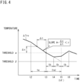
- FIG. 3(a) is a graph schematically showing a temporal change in a difference between the indoor temperature and the target value of the indoor temperature in the cooling operation
- FIG. 3(b) is a graph schematically showing a temporal change in the evaporation temperature of the refrigerant in the indoor heat exchanger and a target value of the evaporation temperature
- FIG. 3(c) is a graph schematically showing a temporal change in the operating frequency of the compressor.
- the difference ⁇ Trs can take not an absolute value but both positive and negative values.
- the outdoor controller 33 controls the operation of the compressor 12 on the basis of the difference ⁇ Trs between the indoor temperature and the target temperature. Specifically, the outdoor controller 33 obtains the difference ⁇ Trs between the indoor temperature and the target temperature as shown in FIG. 3(a) , obtains a target value TeS of an evaporation temperature Te of the refrigerant flowing through the indoor heat exchanger 11 such that the difference ⁇ Trs approaches a predetermined threshold (first threshold) ⁇ as shown in FIG. 3(b) , and controls the operating frequency of the compressor 12 such that the evaporation temperature Te becomes the target value TeS as shown in FIG. 3(c) .
- the outdoor controller 33 sets the target value TeS so as to further decrease the evaporation temperature Te, and controls the compressor 12 so as to increase the operating frequency.
- the outdoor controller 33 sets the target value TeS so as to further increase or maintain the evaporation temperature Te, and controls the compressor 12 so as to decrease or maintain the operating frequency.
- the threshold ⁇ can be set within a range of 0°C to 1.0°C, for example, and is preferably set to 0.5°C.
- the outdoor controller 33 stops the compressor 12 to temporarily stop the cooling operation in order to suppress excessive cooling of the indoor space. Thereafter, when the difference ⁇ Trs increases to a predetermined value or more (for example, up to the threshold ⁇ ), the outdoor controller 33 drives the compressor 12 again to restart the cooling operation.
- the outdoor controller 33 updates the operating frequency of the compressor 12 every predetermined time. Specifically, the outdoor controller 33 controls the operating frequency of the compressor 12 at predetermined update intervals according to the difference ⁇ Trs between the indoor temperature and the target temperature. In the example shown in FIG. 3(a), FIG. 3(b), and FIG. 3(c) , the outdoor controller 33 updates the operating frequency of the compressor 12 at predetermined update intervals ta between times t1 to t3.
- the outdoor controller 33 stops the compressor 12 to temporarily stop the cooling operation when the difference ⁇ Trs reaches the predetermined threshold ⁇ , and drives the compressor 12 to restart the cooling operation when the difference ⁇ Trs increases to a predetermined temperature again. If a frequency (start/stop frequency) of switching between the stop and the drive of the compressor 12 increases due to this operation, a load on the compressor 12 increases, and there is a possibility that operation efficiency decreases.
- the outdoor controller 33 executes processing of shortening the update interval of the operating frequency of the compressor 12. This processing will be described in detail below.
- the outdoor controller 33 updates the operating frequency of the compressor 12 at the update intervals ta.
- the difference ⁇ Trs reaches the threshold value ⁇ at a time point (time point of time t4') until the next update is reached as indicated by a two-dot chain line in FIG. 3(a) , and control is performed to temporarily stop the compressor 12. Therefore, the start/stop frequency of the compressor 12 increases, and there is a possibility that the load on the compressor 12 increases.
- the outdoor controller 33 executes processing of shortening the update interval of the operating frequency of the compressor 12.
- the predetermined condition is as follows.
- the low load operation in the first condition means an operation in which a substitute value indicating an air conditioning load during the cooling operation or the heating operation satisfies a predetermined condition.
- a magnitude of the air conditioning load of the air conditioner 1 can be indicated by the difference ⁇ Trs between the indoor temperature and the set temperature.
- the difference ⁇ Trs is a value obtained by subtracting the set temperature from the indoor temperature during the cooling operation, and is a value obtained by subtracting the indoor temperature from the set temperature during the heating operation. It can be said that the larger the difference ⁇ Trs, the larger the air conditioning load, and it is necessary to increase air conditioning capacity until the indoor temperature reaches the target temperature.
- the difference ⁇ Trs the smaller the air conditioning load, and the air conditioning capacity is not required so much for the indoor temperature to reach the target temperature. Therefore, in the present embodiment, it is set as the first condition that the difference ⁇ Trs indicating the air conditioning load is equal to or less than the predetermined threshold (first threshold) ⁇ .
- the excessive performance operation in the second condition means an operation in which a substitute value indicating a level of the performance of the compressor 12 for the air conditioning load satisfies a predetermined condition during the cooling operation or the heating operation.
- the level of the performance of the compressor 12 for the air conditioning load can be indicated by a change amount of the difference ⁇ Trs in unit time.
- the change amount is a ratio between a predetermined time ⁇ t and a change ⁇ x of the difference ⁇ Trs at the time ⁇ t, and corresponds to a slope A ( ⁇ x/ ⁇ t) of a graph.
- a condition that the slope A of the graph is equal to or less than a predetermined threshold (second threshold) ⁇ (where ⁇ ⁇ 0) is set as the second condition.
- the outdoor controller 33 shortens the update interval of the operating frequency of the compressor 12 from ta to tb.
- the operating frequency of the compressor 12 can be updated at time t4 before reaching time t4', the difference ⁇ Trs can be turned to rise before reaching the threshold ⁇ , and a temporary stop of the compressor 12 can be prevented.
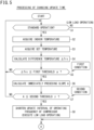
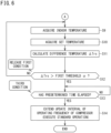
- FIG. 5 and FIG. 6 are flowcharts showing a procedure of processing of changing the update interval of the operating frequency of the compressor.
- an example of the procedure for changing the update interval of the operating frequency of the compressor 12 will be described.
- a normal operation state of the air conditioner 1 in which the first and second conditions are not satisfied (operation state up to time t3 in FIG. 3 ) is referred to as "standard operation”
- an operation state with low load and excessive performance in which the first and second conditions are satisfied is referred to as "low load operation”.
- FIG. 5 and FIG. 6 describe only the processing of changing the update interval of the operating frequency of the compressor 12, and do not include the control of the operating frequency of the compressor 12.
- step S1 in FIG. 5 the outdoor controller 33 determines whether the operation state of the air conditioner 1 is the standard operation.
- the outdoor controller 33 advances the processing to step S2 if the determination in step S1 is positive (Yes), and advances the processing to step S9 (see FIG. 6 ) if the determination is negative (No).
- step S2 the outdoor controller 33 acquires the indoor temperature which is the detection value of the temperature sensor 23.
- step S3 the outdoor controller 33 acquires the target indoor temperature set by the remote controller 24.
- step S4 the outdoor controller 33 calculates the difference ⁇ Trs between the acquired indoor temperature and the target temperature.
- step S5 the outdoor controller 33 determines whether the difference ⁇ Trs is equal to or less than the predetermined threshold ⁇ as the first condition.
- the outdoor controller 33 advances the processing to step S6 if the determination in step S5 is positive (Yes), and returns the processing to step S1 if the determination is negative (No).
- step S7 the outdoor controller 33 determines whether the slope A is equal to or less than the predetermined threshold ⁇ as the second condition. The outdoor controller 33 advances the processing to step S8 if the determination in step S7 is positive (Yes), and returns the processing to step S1 if the determination is negative (No).
- step S8 the outdoor controller 33 shortens the update interval of the operating frequency of the compressor 12. For example, when the update interval is set to 30 seconds in the standard operation, the update interval is set to a shorter time interval, for example, 15 seconds in the low load operation. For example, as shown in FIG. 3 and FIG. 4 , when the first and second conditions are satisfied at time t3, the operating frequency of the compressor 12 is then controlled in accordance with the difference ⁇ Trs at time t4 after the update interval tb has elapsed. As a result, the difference ⁇ Trs increases without reaching the threshold ⁇ , and the temporary stop of the compressor 12 is suppressed.
- the outdoor controller 33 After shifting to the low load operation, the outdoor controller 33 acquires the indoor temperature in step S9 in FIG. 6 . The outdoor controller 33 further acquires the set temperature in step S10. Furthermore, in step S11, the outdoor controller 33 calculates the difference ⁇ Trs between the indoor temperature and the target temperature. In step S12, the outdoor controller 33 determines whether the difference ⁇ Trs exceeds the predetermined threshold ⁇ . This determination is to determine whether the first condition has been released.
- step S12 determines whether the first condition has been released. If the determination in step S12 is positive (Yes), in other words, if the outdoor controller 33 determines that the first condition has been released, the processing proceeds to step S13. On the other hand, if the determination in step S12 is negative (No), in other words, if the outdoor controller 33 determines that the first condition has not been released, the processing returns to step S9.
- step S13 the outdoor controller 33 determines whether a predetermined time tc has elapsed since the first condition is released. This condition is a third condition for returning from the low load operation to the standard operation after the first condition is released. The outdoor controller 33 advances the processing to step S14 after the condition of step S13 is satisfied.
- step S14 the outdoor controller 33 performs processing of extending the update interval of the operating frequency of the compressor 12. Specifically, the outdoor controller 33 performs processing of returning the update interval (for example, 15 seconds) in the low load operation to the update interval (for example, 30 seconds) in the standard operation.
- the update interval is extended from tb to ta at a timing of time t8 after the predetermined time tc has elapsed from a time point when the difference ⁇ Trs exceeds the threshold ⁇ .
- the update interval can be similarly changed for the heating operation.
- the outdoor controller 33 executes the low load operation in which the update interval of the operating frequency of the compressor 12 is shortened.
- the outdoor controller 33 executes the standard operation in which the update interval of the operating frequency of the compressor 12 is extended.
- the update interval of the operating frequency of the compressor 12 is shortened by satisfying the second condition after the first condition is satisfied.
- the update interval of the operating frequency of the compressor 12 may be shortened by satisfying the first condition after the second condition is satisfied.
- the outdoor controller 33 sets the target value of the evaporation temperature or the condensation temperature in the indoor heat exchanger 11 in accordance with the difference ⁇ Trs between the indoor temperature and the target temperature, and controls the operating frequency of the compressor 12 such that the evaporation temperature and the condensation temperature reach the target values.
- the operating frequency of the compressor 12 may be controlled such that the difference ⁇ Trs between the indoor temperature and the target temperature falls within a predetermined range including the predetermined threshold value ⁇ .
- FIG. 7 is an enlarged graph showing a main part of a temporal change in a difference between the indoor temperature and the target value of the indoor temperature during the cooling operation in a second embodiment.
- the update interval of the operating frequency of the compressor 12 is shortened.
- the second embodiment as shown in FIG.
- the outdoor controller 33 shortens the update interval of the operating frequency of the compressor 12 from ta to tb when the change amount of the difference ⁇ Trs per unit time is equal to or less than the predetermined threshold ⁇ (the second condition is satisfied) and it is estimated that the difference ⁇ Trs thereafter becomes equal to or less than the predetermined threshold ⁇ until the predetermined time td elapses (the first condition is satisfied).
- the outdoor controller 33 when the difference ⁇ Trs exceeds the predetermined threshold ⁇ , the outdoor controller 33 performs the control to increase the operating frequency of the compressor 12.
- the outdoor controller when the first condition and the second condition are satisfied, the outdoor controller performs the control to decrease or maintain the operating frequency of the compressor 12 even when the difference ⁇ Trs exceeds the threshold ⁇ . Therefore, when the first condition and the second condition are satisfied, the difference ⁇ Trs is adjusted near the predetermined threshold ⁇ and hardly falls below the threshold ⁇ , and thus, the temporary stop of the compressor 12 can be suppressed and the start/stop frequency can be suppressed.
- the timing of switching between the update interval ta and the update interval tb may be a time point when the first condition and the second condition are satisfied, or may be a time point when the update interval ta ends after the first condition and the second condition are satisfied.
- the time point when the first condition and the second condition are satisfied is a start point of the update interval tb, and the operating frequency of the compressor 12 is updated at this time point.
- the time point at which the update interval ta ends is the start point of the update interval tb, and the operating frequency of the compressor 12 is updated at this time point.
- the former case is more preferable because the operating frequency of the compressor 12 is updated quickly.
- the second condition when the first condition that the difference ⁇ Trs is equal to or less than the predetermined threshold ⁇ is satisfied, the second condition may be that, instead of the change amount of the difference ⁇ Trs per unit time before the first condition is satisfied, the change amount of the difference ⁇ Trs per unit time after the first condition is satisfied is equal to or less than the predetermined threshold ⁇ .
- the condition (third condition) is that the predetermined time tc elapses after the difference ⁇ Trs exceeds the predetermined threshold ⁇ , but the present disclosure is not limited this condition.
- the condition (third condition) may be that the difference ⁇ Trs exceeds another threshold (for example, an upper limit of a dead zone including the threshold ⁇ ) higher than the predetermined threshold ⁇ .
- Several update intervals ta in the standard operation may be set in accordance with the air conditioning load.
- the difference ⁇ Trs is a value obtained by subtracting the target temperature from the indoor temperature during the cooling operation or a value obtained by subtracting the indoor temperature from the target temperature during the heating operation, but may be a value obtained by slightly increasing or decreasing the value by a corrected value.
Landscapes
- Engineering & Computer Science (AREA)
- Mechanical Engineering (AREA)
- General Engineering & Computer Science (AREA)
- Chemical & Material Sciences (AREA)
- Combustion & Propulsion (AREA)
- Physics & Mathematics (AREA)
- Thermal Sciences (AREA)
- Human Computer Interaction (AREA)
- Fuzzy Systems (AREA)
- Mathematical Physics (AREA)
- Signal Processing (AREA)
- Air Conditioning Control Device (AREA)
Abstract
Description
- The present disclosure relates to an air conditioner.
- Conventionally, an air conditioner that performs air conditioning by a refrigerant circulating in a refrigerant circuit is known. The refrigerant circuit includes a heat source-side heat exchanger, a usage-side heat exchanger, and a compressor for circulating the refrigerant. There is also known a technique of temporarily stopping a compressor when an indoor temperature reaches a predetermined target temperature and operating the compressor again when the indoor temperature deviates from the predetermined target temperature (see, for example, Patent Literature 1).
- PATENT LITERATURE 1:
Japanese Patent No. 6072424 - In the technique described in
Patent Literature 1, control is performed in which an operating frequency of the compressor is increased, maintained, or decreased in accordance with a temperature difference between the indoor temperature and the target temperature and a gradient of the temperature difference (a change amount of the temperature difference per unit time) to bring the indoor temperature close to the target temperature. For example, under a situation where an air conditioning load is low and the temperature difference is small, control is performed such that a descending gradient of the temperature difference becomes gentle by lowering the operating frequency of the compressor. When the temperature difference between the indoor temperature and the target temperature falls below a predetermined threshold, the compressor is temporarily stopped to stop air conditioning. - However, in the technique described in
Patent Literature 1, since the operating frequency of the compressor is controlled at regular time intervals (for example, every five minutes), when the descending gradient of the temperature difference is large in a state where the air conditioning load is low, the temperature difference falls below the threshold for temporarily stopping the compressor by the next timing of controlling the operating frequency of the compressor, and there is a possibility that a frequency (hereinafter, also referred to as a "start/stop frequency") at which the compressor is the temporarily stopped and operated again repeatedly becomes high. When the start/stop frequency of the compressor is high, a load on the compressor increases. - An object of the present disclosure is to suppress a start/stop frequency of a compressor.
-
- (1) The present disclosure provides an air conditioner that performs an air conditioning operation in an indoor space, the air conditioner including
- a compressor,
- a controller that controls an operating frequency of the compressor at a predetermined update interval in accordance with an air conditioning load in the indoor space, in which
- the controller shortens the update interval when a first condition indicating that the air conditioning load is low and a second condition indicating that a performance of the compressor is high with respect to the air conditioning load are satisfied.
- In the above configuration, when a condition that the air conditioning load is low and a performance of the compressor is high for the air conditioning load is satisfied, an interval (control interval) for updating the operating frequency of the compressor is shortened. Therefore, the operating frequency of the compressor can be controlled before the compressor is temporarily stopped, and the temporary stop of the compressor can be suppressed. Accordingly, a start/stop frequency of the compressor can be suppressed.
- (2) The first condition preferably includes that a difference between an indoor temperature and a target indoor temperature is equal to or less than a first threshold.
In this configuration, since the difference between the indoor temperature indicating a substantial air conditioning load and the target indoor temperature is equal to or less than the first threshold, it is possible to determine that the load is low. - (3) The second condition preferably includes that a change amount per unit time of a difference between an indoor temperature and a target indoor temperature is equal to or less than a second threshold γ (where γ < 0).
The change amount per unit time of the difference between the indoor temperature and the target indoor temperature indicates a level of performance of the compressor for the air conditioning load, and it can be said that the performance of the compressor is higher for the air conditioning load as the change amount increases in a negative direction when the load is low. Therefore, in the above configuration, it is possible to determine that the performance of the compressor is high for the air conditioning load. - (4) The second condition preferably includes that a change amount per unit time of a difference between an indoor temperature and a target indoor temperature is equal to or less than a second threshold γ (where γ < 0), and
- the first condition preferably includes that, after the second condition is satisfied, the difference is estimated to be less than or equal to a first threshold within a predetermined time on a basis of the change amount.
- In the above configuration, after the second condition is satisfied, a future progress of the difference between the indoor temperature and the target temperature is estimated by using the change amount per unit time of the difference. Then, the update interval of the operating frequency of the compressor can be shortened early, and the compressor can be prevented from reaching the difference in which the compressor temporarily stops.
- (5) The controller preferably maintains a state in which the update interval is shortened until the first condition is released after the first condition and the second condition are satisfied.
Such a configuration can prevent control from being unstable due to frequent switching between shortening and extension of the update interval of the operating frequency of the compressor. - (6) The controller preferably extends the update interval when a third condition set in advance is further satisfied after the first condition is released.
- (7) The third condition preferably includes that a predetermined time elapses.
- (8) The third condition preferably includes that the difference exceeds a third threshold higher than the first threshold.
-
-
FIG. 1 is a schematic refrigerant circuit diagram of an air conditioner according to a first embodiment of the present disclosure. -
FIG. 2 is a block diagram of the air conditioner. -
FIG. 3(a) is a graph schematically showing a temporal change in a difference between an indoor temperature and a target value of the indoor temperature in a cooling operation,FIG. 3(b) is a graph schematically showing a temporal change in an evaporation temperature of a refrigerant in an indoor heat exchanger and a target value of the evaporation temperature, andFIG. 3(c) is a graph schematically showing a temporal change in an operating frequency of a compressor. -
FIG. 4 is an enlarged graph showing a main part of a temporal change in a difference between the indoor temperature and the target value of the indoor temperature during the cooling operation. -
FIG. 5 is a flowchart showing a procedure of processing of changing an update interval of the operating frequency of the compressor. -
FIG. 6 is a flowchart showing the procedure of processing of changing the update interval of the operating frequency of the compressor. -
FIG. 7 is an enlarged graph showing a main part of a temporal change in a difference between the indoor temperature and the target value of the indoor temperature during the cooling operation in a second embodiment. - Embodiments of an air conditioning system will be described in detail with reference to the accompanying drawings.
-
FIG. 1 is a schematic refrigerant circuit diagram of an air conditioner according to a first embodiment of the present disclosure.FIG. 2 is a block diagram of the air conditioner. - The
air conditioner 1 adjusts a temperature of air in an indoor space as an air conditioning target space to a predetermined target temperature. Theair conditioner 1 according to the present embodiment cools and heats the indoor space. Theair conditioner 1 includes anoutdoor unit 2, an indoor unit 3, and arefrigerant circuit 4 that circulates a refrigerant between theoutdoor unit 2 and the indoor unit 3. - The
refrigerant circuit 4 includes acompressor 12, a four-way switching valve 17, an outdoor heat exchanger (heat source heat exchanger) 14, afirst expansion valve 13, areceiver 25, asecond expansion valve 15, aliquid shutoff valve 19, an indoor heat exchanger (utilization heat exchanger) 11, agas shutoff valve 20, anaccumulator 16,refrigerant pipes - The indoor unit 3 includes the
indoor heat exchanger 11 constituting therefrigerant circuit 4. Theindoor heat exchanger 11 is of a cross-fin tube type or a microchannel type, and is used for heat exchange with indoor air. - The indoor unit 3 further includes an
indoor fan 21, anindoor controller 22, anindoor temperature sensor 23, arefrigerant temperature sensor 27, and aremote controller 24. Theindoor fan 21 is configured to take indoor air into the indoor unit 3, cause heat exchange between the taken air and the refrigerant flowing through theindoor heat exchanger 11, and blow the air to the indoor space. Theindoor fan 21 includes a motor having an operating frequency adjustable by inverter control. - The
indoor controller 22 controls an operation of theindoor fan 21. Theindoor controller 22 is constituted by a microcomputer including a calculation unit such as a CPU and a storage such as a RAM or a ROM. Theindoor controller 22 may include an integrated circuit such as an FPGA or an ASIC. - The
indoor temperature sensor 23 measures indoor temperature. Information on the indoor temperature detected by theindoor temperature sensor 23 is transmitted to theindoor controller 22. Theindoor controller 22 transmits the received information on the indoor temperature to anoutdoor controller 33 described later. - The
refrigerant temperature sensor 27 detects a temperature of a refrigerant (gas-liquid two-phase refrigerant) flowing in theindoor heat exchanger 11. When theindoor heat exchanger 11 is an evaporator, the temperature detected by therefrigerant temperature sensor 27 is an evaporation temperature of the refrigerant. When theindoor heat exchanger 11 is a condenser, the temperature detected by therefrigerant temperature sensor 27 is a condensation temperature of the refrigerant. Information on the temperature of the refrigerant detected by therefrigerant temperature sensor 27 is transmitted to theindoor controller 22. Theindoor controller 22 transmits the received information on the temperature of the refrigerant to theoutdoor controller 33 described later. - The
remote controller 24 is used to perform operations such as input of start and stop of an air conditioning operation, input of operating modes of cooling and heating, and input of a target indoor temperature (set temperature). Theremote controller 24 includes a display that displays the operating mode and the set temperature. Theremote controller 24 is connected to theindoor controller 22 in a wired or wireless manner. Information input in theremote controller 24 is transmitted to theindoor controller 22 and theoutdoor controller 33. - The
outdoor unit 2 includes thecompressor 12, the four-way switching valve 17, theoutdoor heat exchanger 14, thefirst expansion valve 13, thereceiver 25, thesecond expansion valve 15, theliquid shutoff valve 19, agas shutoff valve 20, and theaccumulator 16 that constitute therefrigerant circuit 4. - The
compressor 12 sucks a low-pressure gas refrigerant and discharges a highpressure gas refrigerant. Thecompressor 12 includes a motor having an operating frequency adjustable by inverter control. Thecompressor 12 is of a variable displacement type (performance variable type) having capacity (performance) variable by inverter control of the motor. - The four-
way switching valve 17 reverses the flow of refrigerant in the refrigerant pipe and switches and supplies the refrigerant discharged from thecompressor 12 to either theoutdoor heat exchanger 14 or theindoor heat exchanger 11. As a result, theair conditioner 1 can switch between a cooling operation and a heating operation. - The
outdoor heat exchanger 14 is a heat exchanger of a cross-fin tube type or a microchannel type, for example. Theoutdoor heat exchanger 14 exchanges heat with the refrigerant using air as a heat source to condense or evaporate the refrigerant. The first andsecond expansion valves - The
receiver 25 stores excess refrigerant to circulate an appropriate amount of refrigerant in therefrigerant circuit 4. Thereceiver 25 also functions as a gas-liquid separator that separates a liquid phase and a gas phase of the refrigerant. One end of abypass pipe 31 is connected to thereceiver 25, and the other end of thebypass pipe 31 is connected to a refrigerant pipe between the four-way switching valve 17 and theaccumulator 16. Thebypass pipe 31 is provided with anelectromagnetic valve 26 that opens and closes a flow path. - The
accumulator 16 temporarily reserves a low-pressure refrigerant to be sucked into thecompressor 12 to separate a gas refrigerant and a liquid refrigerant. Theliquid shutoff valve 19 is a manually operated on-off valve. Thegas shutoff valve 20 is also a manually operated on-off valve. Theliquid shutoff valve 19 and thegas shutoff valve 20 are closed to block refrigerant flows in therefrigerant pipes refrigerant pipes - The
outdoor unit 2 further includes anoutdoor fan 18,temperature sensors outdoor fan 18 includes a motor having an operating frequency adjustable by inverter control. Theoutdoor fan 18 is configured to take outdoor air into theoutdoor unit 2, cause heat exchange with the taken air and the refrigerant flowing through theoutdoor heat exchanger 14, and blow the air to outside of theoutdoor unit 2. - The
temperature sensors refrigerant temperature sensors refrigerant temperature sensor 28 detects a temperature of a refrigerant (gas-liquid two-phase refrigerant) flowing through theoutdoor heat exchanger 14. When theoutdoor heat exchanger 14 is an evaporator, the temperature detected by therefrigerant temperature sensor 28 is an evaporation temperature of the refrigerant. When theoutdoor heat exchanger 14 is a condenser, the temperature detected by therefrigerant temperature sensor 28 is a condensation temperature of the refrigerant. Therefrigerant temperature sensor 29 detects the temperature of the refrigerant sucked into thecompressor 12. Therefrigerant temperature sensor 30 detects the temperature of the refrigerant discharged from thecompressor 12. - The evaporation temperature and the condensation temperature of the refrigerant, a degree of superheating of the refrigerant, a degree of subcooling of the refrigerant, and the like in the
outdoor heat exchanger 14 and theindoor heat exchanger 11 are obtained by using detection values of therefrigerant temperature sensors compressor 12, opening degrees of the first andsecond expansion valves compressor 12, the evaporation temperature and the condensation temperature of the refrigerant in theoutdoor heat exchanger 14 and theindoor heat exchanger 11, the degree of superheating and the degree of subcooling of the refrigerant, and the like may be obtained by using the values of the pressure sensors and the values of therefrigerant temperature sensors compressor 12, the opening degrees of the first andsecond expansion valves - The
outdoor unit 2 further includes theoutdoor controller 33. Theoutdoor controller 33 is constituted by a microcomputer including a calculation unit such as a CPU and a storage such as a RAM or a ROM. Theoutdoor controller 33 achieves a predetermined function by the calculation unit executing a program stored in the storage. Theoutdoor controller 33 may include an integrated circuit such as an FPGA or an ASIC. Theoutdoor controller 33 is communicably connected to theindoor controller 22 via a transmission line. - The detection values of the
various sensors 28 to 30 provided in theoutdoor unit 2 are input to theoutdoor controller 33. Theoutdoor controller 33 and theindoor controller 22 control operations of thecompressor 12, theexpansion valves outdoor fan 18, theindoor fan 21, and the like on the basis of the detection values of thevarious sensors 27 to 30 and the like. - When the
air conditioner 1 thus configured executes the cooling operation, the four-way switching valve 17 is maintained in a state indicated by solid lines inFIG. 1 . Thecompressor 12 discharges a gas refrigerant having high temperature and high pressure, which flows into theoutdoor heat exchanger 14 via the four-way switching valve 17, and exchanges heat with outdoor air by operation of theoutdoor fan 18 to be condensed and liquefied. The liquefied refrigerant flows into thereceiver 25 through thefirst expansion valve 13. The opening degree of thefirst expansion valve 13 is adjusted such that the degree of subcooling of the refrigerant flowing out of theoutdoor heat exchanger 14 becomes a target value. In thereceiver 25, the refrigerant is separated into a liquid phase and a gas phase, the liquid phase flows into thesecond expansion valve 15, and the gas phase flows into theaccumulator 16 through thebypass pipe 31. The liquid phase of the refrigerant is decompressed by thesecond expansion valve 15 into a gas-liquid two-phase, flows into theindoor heat exchanger 11, exchanges heat with indoor air, and evaporates. The indoor air cooled by the evaporation of the refrigerant is blown into the indoor space by theindoor fan 21 to cool the indoor space. The opening degree of thesecond expansion valve 15 is adjusted such that the degree of superheating of the refrigerant flowing out of theindoor heat exchanger 11 becomes a target value. The refrigerant flowing out of theindoor heat exchanger 11 returns to theoutdoor unit 2 through thegas refrigerant pipe 10G, and is sucked into thecompressor 12 through the four-way switching valve 17 and theaccumulator 16. Theoutdoor controller 33 compares the indoor temperature detected by theindoor temperature sensor 23 with the target temperature, and controls the operating frequency of thecompressor 12 in accordance with a difference between the indoor temperature and the target temperature. - The
outdoor controller 33 performs control to stop the cooling operation by temporarily stopping thecompressor 12 when the indoor temperature drops below the target temperature, and to restart the cooling operation by driving thecompressor 12 when the indoor temperature exceeds the target temperature again. It is therefore possible to suppress excessive cooling of the indoor space. - When the
air conditioner 1 executes the heating operation, the four-way switching valve 17 is maintained in a state indicated by broken lines inFIG. 1 . Thecompressor 12 discharges the gas refrigerant having high temperature and high pressure, which flows into theindoor heat exchanger 11 of the indoor unit 3 through the four-way switching valve 17. In theindoor heat exchanger 11, the refrigerant exchanges heat with indoor air to be condensed and liquefied. The indoor air heated by the condensation of the refrigerant is blown into the indoor space by theindoor fan 21 to heat the indoor space. The refrigerant liquefied in theindoor heat exchanger 11 returns to theoutdoor unit 2 through the liquidrefrigerant pipe 10L, and flows into thereceiver 25 through thesecond expansion valve 15. The opening degree of thesecond expansion valve 15 is adjusted such that the degree of subcooling of the refrigerant flowing out of theindoor heat exchanger 11 becomes a target value. In thereceiver 25, the refrigerant is separated into a liquid phase and a gas phase, the liquid phase flows into thefirst expansion valve 13, and the gas phase flows into theaccumulator 16 through thebypass pipe 31. The liquid phase of the refrigerant is decompressed by thefirst expansion valve 13 into a gas-liquid two-phase, flows into theoutdoor heat exchanger 14, exchanges heat with outdoor air, and evaporates. The opening degree of thefirst expansion valve 13 is adjusted such that the degree of superheating of the refrigerant flowing out of theoutdoor heat exchanger 14 becomes a target value. The refrigerant evaporated and vaporized in theoutdoor heat exchanger 14 is sucked into thecompressor 12 through the four-way switching valve 17 and theaccumulator 16. Theoutdoor controller 33 compares the indoor temperature detected by theindoor temperature sensor 23 with the target temperature, and controls the operating frequency of thecompressor 12 in accordance with a difference between the indoor temperature and the target temperature. - The
outdoor controller 33 performs control to stop the heating operation by temporarily stopping thecompressor 12 when the indoor temperature increases above the target temperature, and to restart the heating operation by driving thecompressor 12 when the indoor temperature falls below the target temperature again. It is therefore possible to suppress excessive heating of the indoor space. -
FIG. 3(a) is a graph schematically showing a temporal change in a difference between the indoor temperature and the target value of the indoor temperature in the cooling operation,FIG. 3(b) is a graph schematically showing a temporal change in the evaporation temperature of the refrigerant in the indoor heat exchanger and a target value of the evaporation temperature, andFIG. 3(c) is a graph schematically showing a temporal change in the operating frequency of the compressor. - In
FIG. 3(a) , ΔTrs is a difference between the indoor temperature and the target temperature (= indoor temperature - target temperature (during the cooling operation)). The difference ΔTrs can take not an absolute value but both positive and negative values. As described above, theoutdoor controller 33 controls the operation of thecompressor 12 on the basis of the difference ΔTrs between the indoor temperature and the target temperature. Specifically, theoutdoor controller 33 obtains the difference ΔTrs between the indoor temperature and the target temperature as shown inFIG. 3(a) , obtains a target value TeS of an evaporation temperature Te of the refrigerant flowing through theindoor heat exchanger 11 such that the difference ΔTrs approaches a predetermined threshold (first threshold) α as shown inFIG. 3(b) , and controls the operating frequency of thecompressor 12 such that the evaporation temperature Te becomes the target value TeS as shown inFIG. 3(c) . - For example, when the difference ΔTrs is larger than the predetermined threshold α, the
outdoor controller 33 sets the target value TeS so as to further decrease the evaporation temperature Te, and controls thecompressor 12 so as to increase the operating frequency. On the other hand, when the difference ΔTrs is smaller than the predetermined threshold α, theoutdoor controller 33 sets the target value TeS so as to further increase or maintain the evaporation temperature Te, and controls thecompressor 12 so as to decrease or maintain the operating frequency. The threshold α can be set within a range of 0°C to 1.0°C, for example, and is preferably set to 0.5°C. - On the other hand, when the difference ΔTrs between the indoor temperature and the target temperature reaches a threshold β which is lower than the threshold α, the
outdoor controller 33 stops thecompressor 12 to temporarily stop the cooling operation in order to suppress excessive cooling of the indoor space. Thereafter, when the difference ΔTrs increases to a predetermined value or more (for example, up to the threshold α), theoutdoor controller 33 drives thecompressor 12 again to restart the cooling operation. - The
outdoor controller 33 updates the operating frequency of thecompressor 12 every predetermined time. Specifically, theoutdoor controller 33 controls the operating frequency of thecompressor 12 at predetermined update intervals according to the difference ΔTrs between the indoor temperature and the target temperature. In the example shown inFIG. 3(a), FIG. 3(b), and FIG. 3(c) , theoutdoor controller 33 updates the operating frequency of thecompressor 12 at predetermined update intervals ta between times t1 to t3. - As described above, the
outdoor controller 33 stops thecompressor 12 to temporarily stop the cooling operation when the difference ΔTrs reaches the predetermined threshold β, and drives thecompressor 12 to restart the cooling operation when the difference ΔTrs increases to a predetermined temperature again. If a frequency (start/stop frequency) of switching between the stop and the drive of thecompressor 12 increases due to this operation, a load on thecompressor 12 increases, and there is a possibility that operation efficiency decreases. - In the
air conditioner 1 according to the present embodiment, in order to reduce the start/stop frequency of thecompressor 12 as described above, theoutdoor controller 33 executes processing of shortening the update interval of the operating frequency of thecompressor 12. This processing will be described in detail below. - As shown in
FIG. 3(a) , when the difference ΔTrs is higher than the threshold α, theoutdoor controller 33 updates the operating frequency of thecompressor 12 at the update intervals ta. However, if the operating frequency of thecompressor 12 is updated at the update intervals ta even after the difference ΔTrs reaches the threshold value α, the difference ΔTrs reaches the threshold value β at a time point (time point of time t4') until the next update is reached as indicated by a two-dot chain line inFIG. 3(a) , and control is performed to temporarily stop thecompressor 12. Therefore, the start/stop frequency of thecompressor 12 increases, and there is a possibility that the load on thecompressor 12 increases. - When the difference ΔTrs between the indoor temperature and the target temperature satisfies a predetermined condition, the
outdoor controller 33 according to the present embodiment executes processing of shortening the update interval of the operating frequency of thecompressor 12. Specifically, the predetermined condition is as follows. - First condition: Low air conditioning load (low load operation)
- Second condition: High performance of compressor for air conditioning load (excessive performance operation)
- The low load operation in the first condition means an operation in which a substitute value indicating an air conditioning load during the cooling operation or the heating operation satisfies a predetermined condition. For example, a magnitude of the air conditioning load of the
air conditioner 1 can be indicated by the difference ΔTrs between the indoor temperature and the set temperature. The difference ΔTrs is a value obtained by subtracting the set temperature from the indoor temperature during the cooling operation, and is a value obtained by subtracting the indoor temperature from the set temperature during the heating operation. It can be said that the larger the difference ΔTrs, the larger the air conditioning load, and it is necessary to increase air conditioning capacity until the indoor temperature reaches the target temperature. On the other hand, it can be said that the smaller the difference ΔTrs, the smaller the air conditioning load, and the air conditioning capacity is not required so much for the indoor temperature to reach the target temperature. Therefore, in the present embodiment, it is set as the first condition that the difference ΔTrs indicating the air conditioning load is equal to or less than the predetermined threshold (first threshold) α. - The excessive performance operation in the second condition means an operation in which a substitute value indicating a level of the performance of the
compressor 12 for the air conditioning load satisfies a predetermined condition during the cooling operation or the heating operation. For example, the level of the performance of thecompressor 12 for the air conditioning load can be indicated by a change amount of the difference ΔTrs in unit time. As shown inFIG. 4 , the change amount is a ratio between a predetermined time Δt and a change Δx of the difference ΔTrs at the time Δt, and corresponds to a slope A (Δx/Δt) of a graph. The smaller the slope A, in other words, the larger a downward gradient of the slope A, the higher the air conditioning capacity (excessive performance) for the air conditioning load. In the present embodiment, a condition that the slope A of the graph is equal to or less than a predetermined threshold (second threshold) γ (where γ < 0) is set as the second condition. - In the example shown in
FIG. 4 , since the difference ΔTrs reaches the threshold α at time t3, the first condition is satisfied. At time t3, the slope A (Δx/Δt) of the immediately preceding difference ΔTrs is equal to or less than the predetermined threshold γ, and the second condition is satisfied. Therefore, theoutdoor controller 33 shortens the update interval of the operating frequency of thecompressor 12 from ta to tb. As a result, the operating frequency of thecompressor 12 can be updated at time t4 before reaching time t4', the difference ΔTrs can be turned to rise before reaching the threshold β, and a temporary stop of thecompressor 12 can be prevented. -
FIG. 5 andFIG. 6 are flowcharts showing a procedure of processing of changing the update interval of the operating frequency of the compressor. Hereinafter, an example of the procedure for changing the update interval of the operating frequency of thecompressor 12 will be described. In the following description, a normal operation state of theair conditioner 1 in which the first and second conditions are not satisfied (operation state up to time t3 inFIG. 3 ) is referred to as "standard operation", and an operation state with low load and excessive performance in which the first and second conditions are satisfied is referred to as "low load operation".FIG. 5 andFIG. 6 describe only the processing of changing the update interval of the operating frequency of thecompressor 12, and do not include the control of the operating frequency of thecompressor 12. - In step S1 in
FIG. 5 , theoutdoor controller 33 determines whether the operation state of theair conditioner 1 is the standard operation. Theoutdoor controller 33 advances the processing to step S2 if the determination in step S1 is positive (Yes), and advances the processing to step S9 (seeFIG. 6 ) if the determination is negative (No). - In step S2, the
outdoor controller 33 acquires the indoor temperature which is the detection value of thetemperature sensor 23. Next, in step S3, theoutdoor controller 33 acquires the target indoor temperature set by theremote controller 24. In step S4, theoutdoor controller 33 calculates the difference ΔTrs between the acquired indoor temperature and the target temperature. - In step S5, the
outdoor controller 33 determines whether the difference ΔTrs is equal to or less than the predetermined threshold α as the first condition. Theoutdoor controller 33 advances the processing to step S6 if the determination in step S5 is positive (Yes), and returns the processing to step S1 if the determination is negative (No). - In step S6, the
outdoor controller 33 calculates the change amount of the difference ΔTrs per unit time immediately before the condition in step S5 is satisfied. In other words, theoutdoor controller 33 calculates the ratio (the slope A (= Δx/Δt) of the graph) between the predetermined time Δt and the change Δx of the difference ΔTrs at the time Δt. In step S7, theoutdoor controller 33 determines whether the slope A is equal to or less than the predetermined threshold γ as the second condition. Theoutdoor controller 33 advances the processing to step S8 if the determination in step S7 is positive (Yes), and returns the processing to step S1 if the determination is negative (No). - In step S8, the
outdoor controller 33 shortens the update interval of the operating frequency of thecompressor 12. For example, when the update interval is set to 30 seconds in the standard operation, the update interval is set to a shorter time interval, for example, 15 seconds in the low load operation. For example, as shown inFIG. 3 andFIG. 4 , when the first and second conditions are satisfied at time t3, the operating frequency of thecompressor 12 is then controlled in accordance with the difference ΔTrs at time t4 after the update interval tb has elapsed. As a result, the difference ΔTrs increases without reaching the threshold β, and the temporary stop of thecompressor 12 is suppressed. - After shifting to the low load operation, the
outdoor controller 33 acquires the indoor temperature in step S9 inFIG. 6 . Theoutdoor controller 33 further acquires the set temperature in step S10. Furthermore, in step S11, theoutdoor controller 33 calculates the difference ΔTrs between the indoor temperature and the target temperature. In step S12, theoutdoor controller 33 determines whether the difference ΔTrs exceeds the predetermined threshold α. This determination is to determine whether the first condition has been released. - If the determination in step S12 is positive (Yes), in other words, if the
outdoor controller 33 determines that the first condition has been released, the processing proceeds to step S13. On the other hand, if the determination in step S12 is negative (No), in other words, if theoutdoor controller 33 determines that the first condition has not been released, the processing returns to step S9. - In step S13, the
outdoor controller 33 determines whether a predetermined time tc has elapsed since the first condition is released. This condition is a third condition for returning from the low load operation to the standard operation after the first condition is released. Theoutdoor controller 33 advances the processing to step S14 after the condition of step S13 is satisfied. - In step S14, the
outdoor controller 33 performs processing of extending the update interval of the operating frequency of thecompressor 12. Specifically, theoutdoor controller 33 performs processing of returning the update interval (for example, 15 seconds) in the low load operation to the update interval (for example, 30 seconds) in the standard operation. In the example shown inFIG. 3 , the update interval is extended from tb to ta at a timing of time t8 after the predetermined time tc has elapsed from a time point when the difference ΔTrs exceeds the threshold α. - By extending the update interval as described above, frequent control of the operating frequency of the
compressor 12 is suppressed, and a stable air conditioning operation can be performed. - Although the cooling operation has been described above, the update interval can be similarly changed for the heating operation. Specifically, the
outdoor controller 33 calculates the difference ΔTrs (= target temperature - indoor temperature) between the indoor temperature and the target indoor temperature, obtains a target value of the condensation temperature in theindoor heat exchanger 11 in accordance with the difference ΔTrs, and controls the operating frequency of thecompressor 12 at predetermined update intervals (for example, 30 seconds) such that the condensation temperature becomes the target value. When the difference ΔTrs reaches the threshold α as the first condition and the change amount of the difference ΔTrs in unit time is equal to or less than the predetermined threshold γ as the second condition, theoutdoor controller 33 executes the low load operation in which the update interval of the operating frequency of thecompressor 12 is shortened. When the difference ΔTrs exceeds the threshold α during the low load operation, and then the predetermined time tc elapses, theoutdoor controller 33 executes the standard operation in which the update interval of the operating frequency of thecompressor 12 is extended. - In the above embodiment, the update interval of the operating frequency of the
compressor 12 is shortened by satisfying the second condition after the first condition is satisfied. However, the update interval of the operating frequency of thecompressor 12 may be shortened by satisfying the first condition after the second condition is satisfied. - In the above embodiment, the
outdoor controller 33 sets the target value of the evaporation temperature or the condensation temperature in theindoor heat exchanger 11 in accordance with the difference ΔTrs between the indoor temperature and the target temperature, and controls the operating frequency of thecompressor 12 such that the evaporation temperature and the condensation temperature reach the target values. However, the operating frequency of thecompressor 12 may be controlled such that the difference ΔTrs between the indoor temperature and the target temperature falls within a predetermined range including the predetermined threshold value α. -
FIG. 7 is an enlarged graph showing a main part of a temporal change in a difference between the indoor temperature and the target value of the indoor temperature during the cooling operation in a second embodiment. - In the first embodiment, when the difference ΔTrs between the indoor temperature and the target temperature is equal to or less than the predetermined threshold α (the first condition is satisfied) and the change amount of the difference ΔTrs per unit time is equal to or less than the predetermined threshold γ (the second condition is satisfied), the update interval of the operating frequency of the
compressor 12 is shortened. In the second embodiment, as shown inFIG. 7 , theoutdoor controller 33 shortens the update interval of the operating frequency of thecompressor 12 from ta to tb when the change amount of the difference ΔTrs per unit time is equal to or less than the predetermined threshold γ (the second condition is satisfied) and it is estimated that the difference ΔTrs thereafter becomes equal to or less than the predetermined threshold α until the predetermined time td elapses (the first condition is satisfied). - Furthermore, in the first embodiment, when the difference ΔTrs exceeds the predetermined threshold α, the
outdoor controller 33 performs the control to increase the operating frequency of thecompressor 12. However, in the second embodiment, when the first condition and the second condition are satisfied, the outdoor controller performs the control to decrease or maintain the operating frequency of thecompressor 12 even when the difference ΔTrs exceeds the threshold α. Therefore, when the first condition and the second condition are satisfied, the difference ΔTrs is adjusted near the predetermined threshold α and hardly falls below the threshold β, and thus, the temporary stop of thecompressor 12 can be suppressed and the start/stop frequency can be suppressed. - In the above embodiment, the timing of switching between the update interval ta and the update interval tb may be a time point when the first condition and the second condition are satisfied, or may be a time point when the update interval ta ends after the first condition and the second condition are satisfied. In the former case, the time point when the first condition and the second condition are satisfied is a start point of the update interval tb, and the operating frequency of the
compressor 12 is updated at this time point. In the latter case, the time point at which the update interval ta ends is the start point of the update interval tb, and the operating frequency of thecompressor 12 is updated at this time point. The former case is more preferable because the operating frequency of thecompressor 12 is updated quickly. - In the first embodiment, when the first condition that the difference ΔTrs is equal to or less than the predetermined threshold α is satisfied, the second condition may be that, instead of the change amount of the difference ΔTrs per unit time before the first condition is satisfied, the change amount of the difference ΔTrs per unit time after the first condition is satisfied is equal to or less than the predetermined threshold γ.
- In the first embodiment, in order to return from the low load operation to the standard operation, the condition (third condition) is that the predetermined time tc elapses after the difference ΔTrs exceeds the predetermined threshold α, but the present disclosure is not limited this condition. For example, the condition (third condition) may be that the difference ΔTrs exceeds another threshold (for example, an upper limit of a dead zone including the threshold α) higher than the predetermined threshold α. Several update intervals ta in the standard operation may be set in accordance with the air conditioning load.
- The difference ΔTrs is a value obtained by subtracting the target temperature from the indoor temperature during the cooling operation or a value obtained by subtracting the indoor temperature from the target temperature during the heating operation, but may be a value obtained by slightly increasing or decreasing the value by a corrected value.
-
- (1) The
air conditioner 1 according to the above embodiment includes thecompressor 12 and thecontroller 33 that controls the operating frequency of thecompressor 12 at a predetermined update interval in accordance with the air conditioning load in the indoor space. Thecontroller 33 shortens the update interval when the first condition indicating that the air conditioning load is low and the second condition indicating that the performance of thecompressor 12 to the air conditioning load is high are satisfied. Therefore, when a condition that the air conditioning load is low and a performance of thecompressor 12 is high for the air conditioning load is satisfied, an interval (control interval) for updating the operating frequency of thecompressor 12 is shortened. Therefore, the operating frequency of thecompressor 12 can be controlled before thecompressor 12 is temporarily stopped. As a result, it is possible to suppress frequent occurrence of temporary stop and restart of the operation of thecompressor 12. - (2) In the first embodiment, the first condition includes that a difference ΔTrs between an indoor temperature and a target indoor temperature is equal to or less than a first threshold α. In this manner, since the difference ΔTrs between the indoor temperature and the target indoor temperature is equal to or less than the first threshold α, it is possible to determine that the load is low.
- (3) In the first embodiment, the second condition includes that a change amount per unit time of the difference ΔTrs between the indoor temperature and the target indoor temperature is equal to or less than a second threshold γ (where γ < 0). In this manner, the change amount per unit time of the difference ΔTrs between the indoor temperature and the target indoor temperature indicates a level of performance of the
compressor 12 for the air conditioning load, and it can be said that the performance of thecompressor 12 is higher for the air conditioning load as the change amount increases in a negative direction when the load is low. Therefore, in the above configuration, it is possible to determine that the performance of thecompressor 12 is high for the air conditioning load. - (4) In the second embodiment, the second condition includes that the change amount per unit time of the difference ΔTrs between the indoor temperature and the target indoor temperature is equal to or less than the second threshold γ (where γ < 0), and the first condition includes that, after the second condition is satisfied, the difference ΔTrs is estimated to be less than or equal to the first threshold α within a predetermined time td on the basis of the change amount. In this configuration, after the second condition is satisfied, a future progress of the difference ΔTrs between the indoor temperature and the target temperature is estimated by using the change amount of the difference ΔTrs. Then, the update interval of the operating frequency of the
compressor 12 can be shortened early, and the difference ΔTrs can be prevented from reaching the threshold β for temporarily stopping thecompressor 12. - (5) In the above embodiment, the
controller 33 maintains a state in which the update interval is shortened until the first condition is released after the first condition and the second condition are satisfied. It is therefore possible to prevent control from being unstable due to frequent switching between shortening and extension of the update interval of the operating frequency of thecompressor 12. - (6) In the above embodiment, the
controller 33 extends the update interval when a predetermined third condition set in advance is further satisfied after the first condition is released. Therefore, the state in which the update interval is shortened can be maintained until the third condition is satisfied after the first condition is released, and it is possible to prevent control from being unstable due to frequent switching between shortening and extension of the update interval of the operating frequency of thecompressor 12. - (7) In the above embodiment, the third condition includes that the predetermined time tc elapses after the first condition is released. Alternatively, the third condition includes that the difference ΔTrs exceeds a third threshold higher than the first threshold α. In either case, the update interval is extended after a certain time elapses after the first condition is released, and it is possible to suppress frequent switching between shortening and extension of the update interval of the operating frequency of the
compressor 12. - The present disclosure should not be limited to the above exemplification, but is intended to include any changes recited in the claims within meanings and a scope equivalent to those of the claims.
-
- 1
- air conditioner
- 12
- compressor
- 33
- outdoor controller
- ta
- update interval
- tb
- update interval
- α
- threshold (first threshold)
- γ
- threshold (second threshold)
Claims (8)
- An air conditioner that performs an air conditioning operation in an indoor space, the air conditioner comprising:a compressor (12);a controller (33) that controls an operating frequency of the compressor (12) at a predetermined update interval in accordance with an air conditioning load in the indoor space, whereinthe controller (33) shortens the update interval when a first condition indicating that the air conditioning load is low and a second condition indicating that a performance of the compressor is high with respect to the air conditioning load are satisfied.
- The air conditioner according to claim 1, wherein the first condition includes that a difference (ΔTrs) between an indoor temperature and a target indoor temperature is equal to or less than a first threshold (α).
- The air conditioner according to claim 1 or 2, wherein the second condition includes that a change amount per unit time of a difference (ΔTrs) between an indoor temperature and a target indoor temperature is equal to or less than a second threshold (γ) (where γ < 0).
- The air conditioner according to claim 1, whereinthe second condition includes that a change amount per unit time of a difference (ΔTrs) between an indoor temperature and a target indoor temperature is equal to or less than a second threshold (γ) (where γ < 0), andthe first condition includes that, after the second condition is satisfied, the difference (ΔTrs) is estimated to be less than or equal to a first threshold (α) within a predetermined time (td) on a basis of the change amount.
- The air conditioner according to any one of claims 1 to 4, wherein the controller (33) maintains a state in which the update interval is shortened until the first condition is released after the first condition and the second condition are satisfied.
- The air conditioner according to claim 5, wherein the controller (33) extends the update interval when a predetermined third condition set in advance is further satisfied after the first condition is released.
- The air conditioner according to claim 6, wherein the third condition includes that a predetermined time (tc) elapses.
- The air conditioner according to claim 6 or 7, wherein the third condition includes that the difference (ΔTrs) exceeds a third threshold higher than the first threshold (α).
Applications Claiming Priority (2)
| Application Number | Priority Date | Filing Date | Title |
|---|---|---|---|
| JP2021186435A JP7637036B2 (en) | 2021-11-16 | 2021-11-16 | Air conditioners |
| PCT/JP2022/038674 WO2023090024A1 (en) | 2021-11-16 | 2022-10-18 | Air conditioner |
Publications (2)
| Publication Number | Publication Date |
|---|---|
| EP4435341A1 true EP4435341A1 (en) | 2024-09-25 |
| EP4435341A4 EP4435341A4 (en) | 2025-03-05 |
Family
ID=86396856
Family Applications (1)
| Application Number | Title | Priority Date | Filing Date |
|---|---|---|---|
| EP22895310.5A Pending EP4435341A4 (en) | 2021-11-16 | 2022-10-18 | AIR CONDITIONING |
Country Status (5)
| Country | Link |
|---|---|
| US (1) | US20240271818A1 (en) |
| EP (1) | EP4435341A4 (en) |
| JP (1) | JP7637036B2 (en) |
| CN (1) | CN118251573A (en) |
| WO (1) | WO2023090024A1 (en) |
Families Citing this family (1)
| Publication number | Priority date | Publication date | Assignee | Title |
|---|---|---|---|---|
| KR20250123583A (en) * | 2024-02-08 | 2025-08-18 | 엘지전자 주식회사 | Refrigerator and method for controlling the same |
Family Cites Families (7)
| Publication number | Priority date | Publication date | Assignee | Title |
|---|---|---|---|---|
| JPH06185796A (en) * | 1992-12-18 | 1994-07-08 | Fujitsu General Ltd | Controlling method of air conditioner |
| JP4311983B2 (en) * | 2003-05-30 | 2009-08-12 | 三洋電機株式会社 | Cooling system |
| JP2006207983A (en) * | 2005-01-31 | 2006-08-10 | Toshiba Kyaria Kk | Air conditioner |
| JP5244414B2 (en) * | 2008-02-05 | 2013-07-24 | 日立アプライアンス株式会社 | Air conditioner |
| JP6072424B2 (en) | 2012-04-13 | 2017-02-01 | 三菱電機株式会社 | Air conditioner |
| JP2014142168A (en) * | 2012-12-28 | 2014-08-07 | Daikin Ind Ltd | Refrigeration equipment |
| CN108779939B (en) * | 2016-03-22 | 2021-02-09 | 三菱电机株式会社 | Refrigerating device |
-
2021
- 2021-11-16 JP JP2021186435A patent/JP7637036B2/en active Active
-
2022
- 2022-10-18 EP EP22895310.5A patent/EP4435341A4/en active Pending
- 2022-10-18 WO PCT/JP2022/038674 patent/WO2023090024A1/en not_active Ceased
- 2022-10-18 CN CN202280076125.5A patent/CN118251573A/en active Pending
-
2024
- 2024-04-24 US US18/644,442 patent/US20240271818A1/en active Pending
Also Published As
| Publication number | Publication date |
|---|---|
| CN118251573A (en) | 2024-06-25 |
| WO2023090024A1 (en) | 2023-05-25 |
| EP4435341A4 (en) | 2025-03-05 |
| US20240271818A1 (en) | 2024-08-15 |
| JP7637036B2 (en) | 2025-02-27 |
| JP2023073766A (en) | 2023-05-26 |
Similar Documents
| Publication | Publication Date | Title |
|---|---|---|
| EP2270405B1 (en) | Refrigerating device | |
| EP2320151B1 (en) | Air-conditioning device | |
| EP3361184B1 (en) | Refrigeration cycle device | |
| EP2924370A1 (en) | Air conditioner and method for controlling an air conditioner | |
| CN113614463B (en) | Air conditioner | |
| CN101688699A (en) | Freezing apparatus | |
| CN108369046B (en) | Refrigeration cycle device | |
| US20150176879A1 (en) | Air-conditioning apparatus | |
| EP3252395B1 (en) | Air conditioning device | |
| US11262108B2 (en) | Refrigeration cycle apparatus | |
| CN101163926B (en) | Air conditioner | |
| EP2372272A1 (en) | Refrigeration equipment | |
| WO2018029763A1 (en) | Air conditioner | |
| US20240271818A1 (en) | Air conditioner | |
| CN110709649B (en) | Refrigeration cycle device | |
| JP2008190759A (en) | Air conditioner | |
| EP4317834A1 (en) | Refrigeration cycle device | |
| JP2011007482A (en) | Air conditioner | |
| JP6588645B2 (en) | Refrigeration cycle equipment | |
| US11835273B2 (en) | Refrigerant cycle apparatus | |
| US11015851B2 (en) | Refrigeration cycle device | |
| CN111148949B (en) | Refrigerating device | |
| JP2020176732A (en) | Air conditioner | |
| EP2918947A1 (en) | Air conditioner | |
| JP2003106615A (en) | Air conditioner |
Legal Events
| Date | Code | Title | Description |
|---|---|---|---|
| STAA | Information on the status of an ep patent application or granted ep patent |
Free format text: STATUS: THE INTERNATIONAL PUBLICATION HAS BEEN MADE |
|
| PUAI | Public reference made under article 153(3) epc to a published international application that has entered the european phase |
Free format text: ORIGINAL CODE: 0009012 |
|
| STAA | Information on the status of an ep patent application or granted ep patent |
Free format text: STATUS: REQUEST FOR EXAMINATION WAS MADE |
|
| 17P | Request for examination filed |
Effective date: 20240516 |
|
| AK | Designated contracting states |
Kind code of ref document: A1 Designated state(s): AL AT BE BG CH CY CZ DE DK EE ES FI FR GB GR HR HU IE IS IT LI LT LU LV MC ME MK MT NL NO PL PT RO RS SE SI SK SM TR |
|
| P01 | Opt-out of the competence of the unified patent court (upc) registered |
Free format text: CASE NUMBER: APP_1071/2025 Effective date: 20250108 |
|
| DAV | Request for validation of the european patent (deleted) | ||
| DAX | Request for extension of the european patent (deleted) | ||
| A4 | Supplementary search report drawn up and despatched |
Effective date: 20250205 |
|
| RIC1 | Information provided on ipc code assigned before grant |
Ipc: F24F 11/61 20180101ALI20250130BHEP Ipc: F25B 49/02 20060101ALI20250130BHEP Ipc: F24F 11/62 20180101ALI20250130BHEP Ipc: F24F 11/86 20180101AFI20250130BHEP |
|
| STAA | Information on the status of an ep patent application or granted ep patent |
Free format text: STATUS: EXAMINATION IS IN PROGRESS |
|
| 17Q | First examination report despatched |
Effective date: 20250822 |