EP4435336A1 - Air conditioning system, controller, control method, and program - Google Patents
Air conditioning system, controller, control method, and program Download PDFInfo
- Publication number
- EP4435336A1 EP4435336A1 EP24164284.2A EP24164284A EP4435336A1 EP 4435336 A1 EP4435336 A1 EP 4435336A1 EP 24164284 A EP24164284 A EP 24164284A EP 4435336 A1 EP4435336 A1 EP 4435336A1
- Authority
- EP
- European Patent Office
- Prior art keywords
- temperature
- floor
- indoor unit
- space
- unit
- Prior art date
- Legal status (The legal status is an assumption and is not a legal conclusion. Google has not performed a legal analysis and makes no representation as to the accuracy of the status listed.)
- Pending
Links
Images




Classifications
-
- F—MECHANICAL ENGINEERING; LIGHTING; HEATING; WEAPONS; BLASTING
- F24—HEATING; RANGES; VENTILATING
- F24F—AIR-CONDITIONING; AIR-HUMIDIFICATION; VENTILATION; USE OF AIR CURRENTS FOR SCREENING
- F24F1/00—Room units for air-conditioning, e.g. separate or self-contained units or units receiving primary air from a central station
- F24F1/0007—Indoor units, e.g. fan coil units
- F24F1/0011—Indoor units, e.g. fan coil units characterised by air outlets
-
- F—MECHANICAL ENGINEERING; LIGHTING; HEATING; WEAPONS; BLASTING
- F24—HEATING; RANGES; VENTILATING
- F24F—AIR-CONDITIONING; AIR-HUMIDIFICATION; VENTILATION; USE OF AIR CURRENTS FOR SCREENING
- F24F1/00—Room units for air-conditioning, e.g. separate or self-contained units or units receiving primary air from a central station
- F24F1/0007—Indoor units, e.g. fan coil units
- F24F1/0043—Indoor units, e.g. fan coil units characterised by mounting arrangements
- F24F1/0047—Indoor units, e.g. fan coil units characterised by mounting arrangements mounted in the ceiling or at the ceiling
-
- F—MECHANICAL ENGINEERING; LIGHTING; HEATING; WEAPONS; BLASTING
- F24—HEATING; RANGES; VENTILATING
- F24F—AIR-CONDITIONING; AIR-HUMIDIFICATION; VENTILATION; USE OF AIR CURRENTS FOR SCREENING
- F24F1/00—Room units for air-conditioning, e.g. separate or self-contained units or units receiving primary air from a central station
- F24F1/0007—Indoor units, e.g. fan coil units
- F24F1/0043—Indoor units, e.g. fan coil units characterised by mounting arrangements
- F24F1/0053—Indoor units, e.g. fan coil units characterised by mounting arrangements mounted at least partially below the floor; with air distribution below the floor
-
- F—MECHANICAL ENGINEERING; LIGHTING; HEATING; WEAPONS; BLASTING
- F24—HEATING; RANGES; VENTILATING
- F24F—AIR-CONDITIONING; AIR-HUMIDIFICATION; VENTILATION; USE OF AIR CURRENTS FOR SCREENING
- F24F11/00—Control or safety arrangements
- F24F11/50—Control or safety arrangements characterised by user interfaces or communication
- F24F11/54—Control or safety arrangements characterised by user interfaces or communication using one central controller connected to several sub-controllers
-
- F—MECHANICAL ENGINEERING; LIGHTING; HEATING; WEAPONS; BLASTING
- F24—HEATING; RANGES; VENTILATING
- F24F—AIR-CONDITIONING; AIR-HUMIDIFICATION; VENTILATION; USE OF AIR CURRENTS FOR SCREENING
- F24F11/00—Control or safety arrangements
- F24F11/50—Control or safety arrangements characterised by user interfaces or communication
- F24F11/56—Remote control
-
- F—MECHANICAL ENGINEERING; LIGHTING; HEATING; WEAPONS; BLASTING
- F24—HEATING; RANGES; VENTILATING
- F24F—AIR-CONDITIONING; AIR-HUMIDIFICATION; VENTILATION; USE OF AIR CURRENTS FOR SCREENING
- F24F11/00—Control or safety arrangements
- F24F11/62—Control or safety arrangements characterised by the type of control or by internal processing, e.g. using fuzzy logic, adaptive control or estimation of values
- F24F11/63—Electronic processing
-
- F—MECHANICAL ENGINEERING; LIGHTING; HEATING; WEAPONS; BLASTING
- F24—HEATING; RANGES; VENTILATING
- F24F—AIR-CONDITIONING; AIR-HUMIDIFICATION; VENTILATION; USE OF AIR CURRENTS FOR SCREENING
- F24F11/00—Control or safety arrangements
- F24F11/62—Control or safety arrangements characterised by the type of control or by internal processing, e.g. using fuzzy logic, adaptive control or estimation of values
- F24F11/63—Electronic processing
- F24F11/64—Electronic processing using pre-stored data
-
- F—MECHANICAL ENGINEERING; LIGHTING; HEATING; WEAPONS; BLASTING
- F24—HEATING; RANGES; VENTILATING
- F24F—AIR-CONDITIONING; AIR-HUMIDIFICATION; VENTILATION; USE OF AIR CURRENTS FOR SCREENING
- F24F11/00—Control or safety arrangements
- F24F11/70—Control systems characterised by their outputs; Constructional details thereof
- F24F11/80—Control systems characterised by their outputs; Constructional details thereof for controlling the temperature of the supplied air
-
- F—MECHANICAL ENGINEERING; LIGHTING; HEATING; WEAPONS; BLASTING
- F24—HEATING; RANGES; VENTILATING
- F24F—AIR-CONDITIONING; AIR-HUMIDIFICATION; VENTILATION; USE OF AIR CURRENTS FOR SCREENING
- F24F11/00—Control or safety arrangements
- F24F11/89—Arrangement or mounting of control or safety devices
-
- F—MECHANICAL ENGINEERING; LIGHTING; HEATING; WEAPONS; BLASTING
- F24—HEATING; RANGES; VENTILATING
- F24F—AIR-CONDITIONING; AIR-HUMIDIFICATION; VENTILATION; USE OF AIR CURRENTS FOR SCREENING
- F24F3/00—Air-conditioning systems in which conditioned primary air is supplied from one or more central stations to distributing units in the rooms or spaces where it may receive secondary treatment; Apparatus specially designed for such systems
- F24F3/06—Air-conditioning systems in which conditioned primary air is supplied from one or more central stations to distributing units in the rooms or spaces where it may receive secondary treatment; Apparatus specially designed for such systems characterised by the arrangements for the supply of heat-exchange fluid for the subsequent treatment of primary air in the room units
- F24F3/065—Air-conditioning systems in which conditioned primary air is supplied from one or more central stations to distributing units in the rooms or spaces where it may receive secondary treatment; Apparatus specially designed for such systems characterised by the arrangements for the supply of heat-exchange fluid for the subsequent treatment of primary air in the room units with a plurality of evaporators or condensers
-
- F—MECHANICAL ENGINEERING; LIGHTING; HEATING; WEAPONS; BLASTING
- F24—HEATING; RANGES; VENTILATING
- F24F—AIR-CONDITIONING; AIR-HUMIDIFICATION; VENTILATION; USE OF AIR CURRENTS FOR SCREENING
- F24F11/00—Control or safety arrangements
- F24F11/30—Control or safety arrangements for purposes related to the operation of the system, e.g. for safety or monitoring
- F24F11/46—Improving electric energy efficiency or saving
-
- F—MECHANICAL ENGINEERING; LIGHTING; HEATING; WEAPONS; BLASTING
- F24—HEATING; RANGES; VENTILATING
- F24F—AIR-CONDITIONING; AIR-HUMIDIFICATION; VENTILATION; USE OF AIR CURRENTS FOR SCREENING
- F24F2110/00—Control inputs relating to air properties
- F24F2110/10—Temperature
Definitions
- An embodiment of the present invention relates to an air conditioning system, a controller, a control method, and a program.
- Air conditioning system including a first indoor unit and a second indoor unit has been proposed.
- the first indoor unit blows temperature-controlled air from an upper part of a space to the inside of the space.
- the second indoor unit blows temperature-controlled air from under a floor of the space to the inside of the space.
- the air conditioning system is required to reduce deviation in temperature of the space.
- Patent Literature 1 Japanese Patent No. 3263324
- a problem to be solved by the present invention is to provide an air conditioning system, a controller, a control method, and a program capable of reducing deviation in temperature of a space.
- An air conditioning system of an embodiment includes a first indoor unit, a floor temperature sensor, a second indoor unit, and a control unit.
- the first indoor unit blows temperature-controlled air from an upper part of a space to the inside of the space.
- the floor temperature sensor outputs a signal.
- the signal corresponds to a floor temperature as a temperature of a floor surface under the first indoor unit.
- the second indoor unit blows temperature-controlled air from under a floor of the space to the inside of the space.
- the control unit controls an operation of the second indoor unit based on the floor temperature obtained by using the floor temperature sensor.
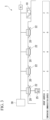
- FIG. 1 is a schematic view for explaining an overview of air conditioning control by the air conditioning system 1 according to the embodiment.
- FIG. 1 shows a vertical cross-sectional view of a portion of a building having a space S.
- the building is, for example, an office building, and the space S is a space.
- the air conditioning system 1 is a system for conditioning air of the space S.
- the air conditioning system 1 includes a plurality of ceiling blowing indoor units 20 (first indoor unit) and, a floor blowing indoor unit 10 (second indoor unit), an outdoor unit, and a remote controller 25 (remote control unit).
- Each of the plurality of the ceiling blowing indoor units 20 is an indoor unit as a ceiling blowing air conditioner.
- Each of the plurality of the ceiling blowing indoor units 20 includes a heat exchanger, a blower, or the like.
- each of the plurality of the ceiling blowing indoor units 20 is a ceiling cassette-type four-direction indoor unit.
- a plurality of the ceiling blowing indoor units 20 are provided at a distance on the ceiling of the space S. The plurality of the ceiling blowing indoor units 20 are provided such that they are evenly distributed in the space S with being balanced.
- the floor blowing indoor unit 10 is an indoor unit as a floor blowing air conditioner.
- the floor blowing indoor unit 10 includes a heat exchanger, a blower, or the like.
- the floor blowing indoor unit 10 are provided above the ceiling of the space S.
- a vertical duct 40 is provided on a side wall of the space S.
- the underfloor portion of the space S is a double floor and functions as an underfloor air supply chamber 45.
- a horizontal duct may be provided instead of the underfloor air supply chamber 45.
- a plurality of blowing outlets 50 are provided on a floor surface of the space S. Air discharged from the floor blowing indoor unit 10 passes through the vertical duct 40 and the underfloor air supply chamber 45 and is blown into the space S from the plurality of the blowing outlets 50.
- the outdoor unit 30 is provided outside the building.
- the outdoor unit 30 includes a compressor, a four-way valve, a heat exchanger, an expansion valve, or the like.
- the plurality of the ceiling blowing indoor units 20 and the floor blowing indoor unit 10 are connected in parallel to each other via a refrigerant pipe 35 with respect to the outdoor unit 30, and they form a refrigeration cycle device.
- the air conditioning system 1 is a multi-type air conditioning system.
- the air conditioning system 1 includes a floor blowing air conditioner in addition to the ceiling blowing air conditioner in combination. Consequently, an upper and lower temperature difference of the space S is reduced. Since the feet of the person becomes warm, the person feels comfortable. Since the set temperature is lowered, energy consumption is reduced.
- FIG. 2 is a block diagram showing an overall configuration of the air conditioning system 1 according to the embodiment.
- the remote controller 25 is an input interface that receives user's input regarding a setting of the air conditioning system 1.
- the remote controller 25 receives the input regarding ON and OFF of a power source of the air conditioning system 1.
- the remote controller 25 receives the input regarding a set temperature of the space S.
- the remote controller 25 outputs a signal corresponding to input information to the ceiling blowing indoor unit 20.
- the ceiling blowing indoor unit 20 includes a suction temperature sensor 21, a floor temperature sensor 22, and a first control unit 23.
- the suction temperature sensor 21 measures the temperature (suction temperature) of the air suctioned into the ceiling blowing indoor unit 20 from the space S.
- the suction temperature sensor 21 outputs a signal corresponding to the suction temperature.
- the floor temperature sensor 22 (radiative temperature sensor) is attached to a panel of the ceiling blowing indoor unit 20.
- the floor temperature sensor 22 measures a radiative temperature of the floor surface under the ceiling blowing indoor unit 20 as a floor temperature.
- the floor temperature sensor 22 measures the average value of the floor temperature in a circular area of approximately 7.5 m in diameter centered directly under the floor temperature sensor 22.
- the floor temperature sensor 22 outputs a signal corresponding to the floor temperature.
- FIG. 3 is an explanatory diagram of address setting with respect to the plurality of the ceiling blowing indoor units 20 and the floor blowing indoor unit 10.
- the plurality of the ceiling blowing indoor units 20 and the floor blowing indoor unit 10 included in the air conditioning system 1 are connected by the same communication line to form a group.
- a group address is set to all units connected to each other to form a group.
- the unit having the group address of "1" is specified to a master unit
- the unit having the group address of "2" is specified to a slave unit.
- One of the plurality of the ceiling blowing indoor units 20 is the master unit (main first indoor unit).
- the remaining of the plurality of the ceiling blowing indoor units 20 and the floor blowing indoor unit 10 are the slave units.
- the remote controller 25 outputs the signal corresponding to input information to the master unit.
- the master unit outputs, to all of the slave units, information input to the remote controller 25.
- the first control unit 23 receives the signal corresponding to the set temperature output from the remote controller 25 or the master unit.
- the first control unit 23 receives the signal corresponding to the suction temperature output from the suction temperature sensor 21.
- the first control unit 23 controls an operation of the ceiling blowing indoor unit 20 based on the set temperature and the suction temperature. Each of the operations of the plurality of the ceiling blowing indoor units 20 is individually controlled by the first control unit 23.
- the first control unit 23 receives the signal corresponding to the floor temperature output from the floor temperature sensor 22.
- the slave unit of the ceiling blowing indoor unit 20 outputs the signal of the floor temperature sensor 22 to the master unit.
- the first control unit 23 of the master unit receives signals of all of the floor temperature sensors 22 and calculates the average value (average floor temperature) of the floor temperature of the space S based on the signals.
- the first control unit 23 of the master unit outputs, to the floor blowing indoor unit 10, the signal corresponding to the calculated average floor temperature.
- a temperature communication (feedback) address is set to all units connected to each other to form a group.
- the unit having the temperature communication address of "1" is specified to the transmission source of the average floor temperature
- the unit having the control temperature address of "2" is specified to the transmission destination of the average floor temperature.
- the unit having the control temperature address of "0" is specified as being excluded for the temperature communication. That is, the master unit is the transmission source of the average floor temperature, and the floor blowing indoor unit 10 is the transmission destination of the average floor temperature.
- the floor blowing indoor unit 10 receives information regarding the average floor temperature calculated by the master unit.
- the floor blowing indoor unit 10 includes a second control unit 11 (control unit, controller).
- the second control unit 11 controls an operation of the floor blowing indoor unit 10 based on the floor temperature (average floor temperature) obtained by using the floor temperature sensor 22.
- the second control unit 11 receives information regarding the set temperature output from the master unit.
- the second control unit 11 receives information regarding the average floor temperature output from the master unit.
- the second control unit 11 controls the operation of the floor blowing indoor unit 10 based on the set temperature and average floor temperature.
- Each of the first control unit 23 and the second control unit 11 includes, for example, a processor such as a central processing unit (CPU) connected via a bus, a memory, an auxiliary storage device, and the like. Each of the first control unit 23 and the second control unit 11 reads and executes a program from, for example, an auxiliary storage device.
- the auxiliary storage device is configured using a storage medium such as, for example, a magnetic hard disk device or a semiconductor storage device.
- the auxiliary storage device is configured using a non-volatile memory such as an electrically erasable programmable read-only memory (EEPROM).
- EEPROM electrically erasable programmable read-only memory
- the program may be stored in a storage (for example, a storage device including a non-transitory storage medium) in advance or may be stored in a removable storage medium (the non-transitory storage medium) such as a digital versatile disc (DVD) or a compact disc (CD)-read-only memory (ROM) and installed when the storage medium is mounted in a drive device.
- a storage for example, a storage device including a non-transitory storage medium
- a removable storage medium such as a digital versatile disc (DVD) or a compact disc (CD)-read-only memory (ROM)
- All or part of the first control unit 23 and the second control unit 11 may be realized by using hardware such as an application specific integrated circuit (ASIC), a programmable logic device (PLD), or a field programmable gate array (FPGA).
- ASIC application specific integrated circuit
- PLD programmable logic device
- FPGA field programmable gate array
- the program may be recorded on a computer-readable recording medium.
- the computer-readable recording medium refers to a portable medium such as, for example, a flexible disk, a magneto-optical disk, a ROM, or a CD-ROM, and a storage device such as a hard disk incorporated in a computer system.
- the program may be transmitted via a telecommunication line.
- FIG. 4 is a flowchart showing an operation of the ceiling blowing indoor unit 20.
- the first control unit 23 of the ceiling blowing indoor unit 20 obtains a set temperature (S12).
- the remote controller 25 outputs a signal corresponding to a set temperature of the space S input by a user.
- the master unit of the ceiling blowing indoor units 20 receives the signal from the remote controller 25.
- the first control unit 23 of the master unit obtains the set temperature from the signal. For example, the master unit obtains 23°C as the set temperature.
- the master unit transmits the obtained set temperature to the slave units.
- the first control unit 23 calculates a first target temperature TS1 (S14).
- the first target temperature TS1 is the target value of the temperature of an upper part of the space S. Due to the effect of rise of warm air, the temperature of the upper part of the space S becomes higher than the temperature (intermediate temperature) of the intermediate part in a height direction of the space S.
- the first target temperature TS1 is the temperature obtained by subtracting a correction value 1a from the set temperature (23°C).
- the correction value 1a is set depending on, for example, the degree of ease of rising the temperature of the space S.
- the correction value 1a of the embodiment is, for example, 0°C, and the first target temperature TS1 is 23°C.
- the first control unit 23 obtains the suction temperature Tb (S 16).
- the suction temperature sensor 21 outputs a signal corresponding to the suction temperature of the ceiling blowing indoor unit 20.
- the first control unit 23 receives the signal from the suction temperature sensor 21 and obtains the suction temperature Tb. For each of the plurality of the ceiling blowing indoor units 20, the first control unit 23 receives the signal from the suction temperature sensor 21 and obtains the suction temperature Tb. For example, in one of the ceiling blowing indoor units 20, the first control unit 23 obtains 10°C as the suction temperature.
- the first control unit 23 obtains a floor temperature Tf (S18).
- the floor temperature sensor 22 outputs a signal corresponding to a floor temperature under the ceiling blowing indoor unit 20.
- the first control unit 23 receives the signal from the floor temperature sensor 22 and obtains the floor temperature Tf. For each of the plurality of the ceiling blowing indoor units 20, the first control unit 23 receives the signal from the floor temperature sensor 22 and obtains the floor temperature Tf under the corresponding ceiling blowing indoor unit 20.
- the first control unit 23 determines whether or not the ceiling blowing indoor unit 20 to which the first control unit 23 belongs is the master unit (S20).
- the first control unit 23 refers to the group address set in the ceiling blowing indoor unit 20, and determines whether or not the ceiling blowing indoor unit 20 to which the first control unit 23 belongs is the master unit. In a case in which the ceiling blowing indoor unit 20 is the slave unit (the determination of S20 is No), that is, in a case in which the group address is not "1" in the embodiment, the first control unit 23 transmits the obtained floor temperature Tf to the master unit (S22).
- the first control unit 23 calculates an average floor temperature Tfa (S24).
- the average floor temperature Tfa is the average value of the floor temperatures Tf obtained by the master unit and all of the slave units. For example, the average floor temperature Tfa calculated by the master unit is 8°C.
- the first control unit 23 of the master unit determines the transmission destination of the calculated average floor temperature Tfa.
- the transmission destination of the average floor temperature Tfa is determined by referring temperature communication addresses set in the units included in the air conditioning system 1.
- the floor blowing indoor unit 10 having the temperature communication address of "2" in the embodiment is the transmission destination of the average floor temperature Tfa.
- the first control unit 23 of the master unit serving as the transmission source of the average floor temperature Tfa transmits the average floor temperature Tfa to the floor blowing indoor unit 10 (S24).
- the first control unit 23 sets a first control target temperature TA1 (S26).
- the first control target temperature TA1 is the temperature of the space S as the control object to be closer to the first target temperature TS1.
- the first target temperature TS1 is the target value of the temperature of an upper part of the space S. Since the ceiling blowing indoor unit 20 is provided on the ceiling of the space S, the suction temperature Tb of the ceiling blowing indoor unit 20 is the temperature of the upper part of the space S.
- the first control unit 23 sets the first control target temperature TA1 by subtracting a correction value 1b from the suction temperature Tb.
- the correction value 1b is set corresponding to, for example, the height of the ceiling blowing indoor unit 20 provided in the space S. For example, the suction temperature Tb of one of the ceiling blowing indoor units 20 is 10°C, the correction value 1b is 0°C, and the first control target temperature TA1 is 10°C.
- the first control unit 23 carries out normal temperature control (S28).
- the first control unit 23 controls the operation of the ceiling blowing indoor unit 20 based on the difference between the first target temperature TS1 (23°C) and the first control target temperature TA1 (10°C).
- the first target temperature TS1 is calculated from the set temperature
- the first control target temperature TA1 is calculated from the suction temperature Tb.
- a specific example of the normal temperature control is as follows.
- a table regarding output of a compressor included in the outdoor unit 30 is recorded in the auxiliary storage device of the first control unit 23.
- the output of the compressor corresponding to the difference between the first target temperature TS1 (23°C) and the first control target temperature TA1 (10°C) is recorded in the table.
- the first control unit 23 refers to the table, and calculates the output of the compressor based on the difference between the first target temperature TS1 and the first control target temperature TA1.
- the first control unit 23 drives the compressor based on the calculated output of the compressor and controls the operation of the ceiling blowing indoor unit 20. Consequently, the first control target temperature TA1 (10°C) comes close to the first target temperature TS1 (23°C).
- the first control unit 23 may calculate an opening angle of the expansion valve included in the outdoor unit 30 instead of the output of the compressor or together with the output of the compressor, and controls the operation of the ceiling blowing indoor unit 20.
- the first control unit 23 determines whether or not it is necessary to complete the operation (S30).
- the remote controller 25 outputs a signal corresponding to an instruction input by the user regarding ON and OFF of the power source of the air conditioning system 1.
- the master unit of the ceiling blowing indoor units 20 receives the signal from the remote controller 25.
- the first control unit 23 of the master unit obtains the instruction regarding ON and OFF of the power source from the signal.
- the instruction of power OFF is obtained (the determination of S30 is Yes)
- the first control unit 23 of the master unit transmits the instruction of the power OFF to the slave unit.
- the first control unit 23 of each of the master unit and the slave unit completes the operation of the corresponding ceiling blowing indoor unit 20.
- the first control unit 23 of each of the master unit and the slave unit repeats the processes following the S16.
- FIG. 5 is a flowchart showing an operation of the floor blowing indoor unit 10.
- the second control unit 11 of the floor blowing indoor unit 10 obtains the set temperature (S42).
- the second control unit 11 obtains information regarding the set temperature (23 °C) from the master unit of the ceiling blowing indoor units 20.
- the second control unit 11 calculates a second target temperature TS2 (S44).
- the second target temperature TS2 is the target value of the temperature of a lower part of the space S. Due to the effect of rise of warm air, the temperature of the lower part of the space S becomes lower than the temperature of the intermediate temperature of the space S.
- the second target temperature TS2 is the temperature obtained by subtracting a correction value 2a from the set temperature (23°C).
- the correction value 2a is set depending on, for example, the degree of ease of rising the temperature of the space S.
- the correction value 2a of the embodiment is, for example, 0°C
- the second target temperature TS2 is 23°C.
- the correction value 2a of the second target temperature TS2 and the correction value 1a of the first target temperature TS1 may be the same as each other or different from each other.
- the second control unit 11 obtains the average floor temperature Tfa (S46).
- the second control unit 11 obtains information regarding the average floor temperature Tfa (8°C) from the master unit of the ceiling blowing indoor units 20 serving as the transmission source of the average floor temperature Tfa.
- the second control unit 11 sets a second control target temperature TA2 (S48).
- the second control target temperature TA2 is the temperature of the space S as the control object to be closer to the second target temperature TS2.
- the second target temperature TS2 is the target value of the temperature of a lower part of the space S.
- the average floor temperature Tfa is the temperature of the lower part of the space S.
- the second control unit 11 sets the second control target temperature TA2 by subtracting a correction value 2b from the average floor temperature Tfa (8°C).
- the correction value 2b is set corresponding to, for example, the height of the space S.
- the correction value 2b of the embodiment is, for example, 0°C
- the second control target temperature TA2 is 8°C.
- the second control unit 11 carries out normal temperature control (S50).
- the second control unit 11 controls the operation of the floor blowing indoor unit 10 based on the difference between the second target temperature TS2 (23°C) and the second control target temperature TA2 (8°C).
- the second target temperature TS2 is calculated from the set temperature
- the second control target temperature TA2 is calculated from the average floor temperature Tfa.
- the second control unit 11 controls an operation of the floor blowing indoor unit 10 based on the floor temperature (average floor temperature Tfa) obtained by using the floor temperature sensor 22.
- a specific example of the normal temperature control is as follows.
- a table regarding output of a compressor included in the outdoor unit 30 is recorded in the auxiliary storage device of the second control unit 11.
- the output of the compressor corresponding to the difference between the second target temperature TS2 (23°C) and the second control target temperature TA2 (8°C) is recorded in the table.
- the second control unit 11 refers to the table, and calculates the output of the compressor based on the difference between the second target temperature TS2 and the second control target temperature TA2.
- the second control unit 11 drives the compressor based on the calculated output of the compressor and controls the operation of the floor blowing indoor unit 10. Consequently, the second control target temperature TA2 (8°C) comes close to the second target temperature TS2 (23°C).
- the compressor is only necessary to be driven based on a higher output in comparison of the two outputs.
- the second control unit 11 may calculate an opening angle of the expansion valve included in the outdoor unit 30 instead of the output of the compressor or together with the output of the compressor, and controls the operation of the floor blowing indoor unit 10.
- the second control unit 11 determines whether or not it is necessary to complete the operation (S52).
- An air conditioning system 1 of a Comparative Example includes a remote thermo sensor instead of the floor temperature sensor 22.
- the remote thermo sensor is provided on the side wall of the space S.
- the remote thermo sensor cannot detect the temperature near the center spaced apart from the side wall of the space S.
- the remote thermo sensor interferes with use of the space S.
- the air conditioning system 1 includes the ceiling blowing indoor unit 20, the floor temperature sensor 22, the floor blowing indoor unit 10, and the second control unit 11.
- the ceiling blowing indoor unit 20 blows temperature-controlled air from the upper part of the space S to the inside of the space S.
- the floor temperature sensor 22 outputs the signal corresponding to the floor temperature as the temperature of the floor surface under the ceiling blowing indoor unit 20.
- the floor blowing indoor unit 10 blows temperature-controlled air from under the floor of the space S to the inside of the space S.
- the second control unit 11 controls the operation of the floor blowing indoor unit 10 based on the floor temperature obtained by using the floor temperature sensor 22.
- the ceiling blowing indoor unit 20 is provided on the ceiling near the center spaced apart from the side wall of the space S.
- the floor temperature sensor 22 detects and measures the temperature of the floor surface near the center spaced apart from the side wall of the space S.
- the floor blowing indoor unit 10 is controlled such that the floor temperature near the center of the space S comes close to the set temperature. Accordingly, it is possible to reduce deviation in temperature of the space S.
- the air conditioning system 1 includes the plurality of the ceiling blowing indoor units 20 and the plurality of the floor temperature sensors 22 corresponding one-to-one to the plurality of the ceiling blowing indoor units 20.
- the master unit serving as the ceiling blowing indoor unit 20 specified in advance from the plurality of the ceiling blowing indoor units 20 calculates the average floor temperature Tfa as the average value floor temperatures obtained by using the plurality of the floor temperature sensors 22.
- the second control unit 11 controls the operation of the floor blowing indoor unit 10 based on the average floor temperature Tfa.
- the plurality of the ceiling blowing indoor units 20 are provided such that they are evenly distributed and provided on the ceiling of the space S.
- the floor temperature on a wide area of the space S is detected and measured by the plurality of the floor temperature sensors 22.
- the average floor temperature Tfa of the space S is detected and measured with a high degree of accuracy by calculating the average floor temperature Tfa using the plurality of the floor temperature sensors 22. Deviation in temperature of the space S is reduced by controlling the operation of the floor blowing indoor unit 10 based on the average floor temperature Tfa.
- the "computer-readable recording medium” may include one that holds a program dynamically for a short period of time such as a communication line in a case in which programs are transmitted via a network such as the Internet or a communication line such as a telephone line, and one that holds a program for a certain period of time such as volatile memories inside a computer system serving as a server or client in the above-described case.
- the above-described program may be a program for realizing some of the above-described functions, further may be a program for realizing the above-described functions in combination with programs already recorded on the computer system, and may be realized by using hardware such as a programmable logic device (PLD), a field programmable gate array (FPGA), or the like.
- PLD programmable logic device
- FPGA field programmable gate array
Landscapes
- Engineering & Computer Science (AREA)
- Chemical & Material Sciences (AREA)
- Combustion & Propulsion (AREA)
- Mechanical Engineering (AREA)
- General Engineering & Computer Science (AREA)
- Signal Processing (AREA)
- Human Computer Interaction (AREA)
- Physics & Mathematics (AREA)
- Fuzzy Systems (AREA)
- Mathematical Physics (AREA)
- Air Conditioning Control Device (AREA)
Abstract
An air conditioning system of an embodiment includes a first indoor unit, a floor temperature sensor, a second indoor unit, and a control unit. The first indoor unit blows temperature-controlled air from an upper part of a space to the inside of the space. The floor temperature sensor outputs a signal. The signal corresponds to a floor temperature as a temperature of a floor surface under the first indoor unit. The second indoor unit blows temperature-controlled air from under a floor of the space to the inside of the space. The control unit controls an operation of the second indoor unit based on the floor temperature obtained by using the floor temperature sensor.
Description
- An embodiment of the present invention relates to an air conditioning system, a controller, a control method, and a program.
- Air conditioning system including a first indoor unit and a second indoor unit has been proposed. The first indoor unit blows temperature-controlled air from an upper part of a space to the inside of the space. The second indoor unit blows temperature-controlled air from under a floor of the space to the inside of the space. The air conditioning system is required to reduce deviation in temperature of the space.
- [Patent Literature 1]
Japanese Patent No. 3263324 - A problem to be solved by the present invention is to provide an air conditioning system, a controller, a control method, and a program capable of reducing deviation in temperature of a space.
- An air conditioning system of an embodiment includes a first indoor unit, a floor temperature sensor, a second indoor unit, and a control unit. The first indoor unit blows temperature-controlled air from an upper part of a space to the inside of the space. The floor temperature sensor outputs a signal. The signal corresponds to a floor temperature as a temperature of a floor surface under the first indoor unit. The second indoor unit blows temperature-controlled air from under a floor of the space to the inside of the space. The control unit controls an operation of the second indoor unit based on the floor temperature obtained by using the floor temperature sensor.
-
-
FIG. 1 is a schematic view for explaining an overview of air conditioning control by an air conditioning system according to an embodiment. -
FIG. 2 is a block diagram showing an overall configuration of the air conditioning system according to the embodiment. -
FIG. 3 is an explanatory diagram of address setting with respect to a plurality of ceiling blowing indoor units and a floor blowing indoor unit. -
FIG. 4 is a flowchart showing an operation of a ceiling blowing indoor unit. -
FIG. 5 is a flowchart showing an operation of a floor blowing indoor unit. - Hereinafter, an air conditioning system, a controller, a control method, and a program according to an embodiment will be described with reference to the drawings.
-
FIG. 1 is a schematic view for explaining an overview of air conditioning control by theair conditioning system 1 according to the embodiment.FIG. 1 shows a vertical cross-sectional view of a portion of a building having a space S. The building is, for example, an office building, and the space S is a space. Theair conditioning system 1 is a system for conditioning air of the space S. Theair conditioning system 1 includes a plurality of ceiling blowing indoor units 20 (first indoor unit) and, a floor blowing indoor unit 10 (second indoor unit), an outdoor unit, and a remote controller 25 (remote control unit). - Each of the plurality of the ceiling blowing
indoor units 20 is an indoor unit as a ceiling blowing air conditioner. Each of the plurality of the ceiling blowingindoor units 20 includes a heat exchanger, a blower, or the like. For example, each of the plurality of the ceiling blowingindoor units 20 is a ceiling cassette-type four-direction indoor unit. A plurality of the ceiling blowingindoor units 20 are provided at a distance on the ceiling of the space S. The plurality of the ceiling blowingindoor units 20 are provided such that they are evenly distributed in the space S with being balanced. - The floor blowing
indoor unit 10 is an indoor unit as a floor blowing air conditioner. The floor blowingindoor unit 10 includes a heat exchanger, a blower, or the like. The floor blowingindoor unit 10 are provided above the ceiling of the space S. Avertical duct 40 is provided on a side wall of the space S. The underfloor portion of the space S is a double floor and functions as an underfloorair supply chamber 45. A horizontal duct may be provided instead of the underfloorair supply chamber 45. A plurality of blowingoutlets 50 are provided on a floor surface of the space S. Air discharged from the floor blowingindoor unit 10 passes through thevertical duct 40 and the underfloorair supply chamber 45 and is blown into the space S from the plurality of the blowingoutlets 50. - The
outdoor unit 30 is provided outside the building. Theoutdoor unit 30 includes a compressor, a four-way valve, a heat exchanger, an expansion valve, or the like. The plurality of the ceiling blowingindoor units 20 and the floor blowingindoor unit 10 are connected in parallel to each other via arefrigerant pipe 35 with respect to theoutdoor unit 30, and they form a refrigeration cycle device. Theair conditioning system 1 is a multi-type air conditioning system. - The
air conditioning system 1 includes a floor blowing air conditioner in addition to the ceiling blowing air conditioner in combination. Consequently, an upper and lower temperature difference of the space S is reduced. Since the feet of the person becomes warm, the person feels comfortable. Since the set temperature is lowered, energy consumption is reduced. -
FIG. 2 is a block diagram showing an overall configuration of theair conditioning system 1 according to the embodiment. - The
remote controller 25 is an input interface that receives user's input regarding a setting of theair conditioning system 1. Theremote controller 25 receives the input regarding ON and OFF of a power source of theair conditioning system 1. Theremote controller 25 receives the input regarding a set temperature of the space S. Theremote controller 25 outputs a signal corresponding to input information to the ceiling blowingindoor unit 20. - The ceiling blowing
indoor unit 20 includes asuction temperature sensor 21, afloor temperature sensor 22, and afirst control unit 23. - The
suction temperature sensor 21 measures the temperature (suction temperature) of the air suctioned into the ceiling blowingindoor unit 20 from the space S. Thesuction temperature sensor 21 outputs a signal corresponding to the suction temperature. - As shown in
FIG. 1 , the floor temperature sensor 22 (radiative temperature sensor) is attached to a panel of the ceiling blowingindoor unit 20. Thefloor temperature sensor 22 measures a radiative temperature of the floor surface under the ceiling blowingindoor unit 20 as a floor temperature. Thefloor temperature sensor 22 measures the average value of the floor temperature in a circular area of approximately 7.5 m in diameter centered directly under thefloor temperature sensor 22. Thefloor temperature sensor 22 outputs a signal corresponding to the floor temperature. -
FIG. 3 is an explanatory diagram of address setting with respect to the plurality of the ceiling blowingindoor units 20 and the floor blowingindoor unit 10. The plurality of the ceiling blowingindoor units 20 and the floor blowingindoor unit 10 included in theair conditioning system 1 are connected by the same communication line to form a group. A group address is set to all units connected to each other to form a group. For example, the unit having the group address of "1" is specified to a master unit, and the unit having the group address of "2" is specified to a slave unit. One of the plurality of the ceiling blowingindoor units 20 is the master unit (main first indoor unit). The remaining of the plurality of the ceiling blowingindoor units 20 and the floor blowingindoor unit 10 are the slave units. Theremote controller 25 outputs the signal corresponding to input information to the master unit. The master unit outputs, to all of the slave units, information input to theremote controller 25. - The
first control unit 23 receives the signal corresponding to the set temperature output from theremote controller 25 or the master unit. Thefirst control unit 23 receives the signal corresponding to the suction temperature output from thesuction temperature sensor 21. Thefirst control unit 23 controls an operation of the ceiling blowingindoor unit 20 based on the set temperature and the suction temperature. Each of the operations of the plurality of the ceiling blowingindoor units 20 is individually controlled by thefirst control unit 23. - For each of the plurality of the ceiling blowing
indoor units 20, thefirst control unit 23 receives the signal corresponding to the floor temperature output from thefloor temperature sensor 22. The slave unit of the ceiling blowingindoor unit 20 outputs the signal of thefloor temperature sensor 22 to the master unit. Thefirst control unit 23 of the master unit receives signals of all of thefloor temperature sensors 22 and calculates the average value (average floor temperature) of the floor temperature of the space S based on the signals. Thefirst control unit 23 of the master unit outputs, to the floor blowingindoor unit 10, the signal corresponding to the calculated average floor temperature. - As mentioned above, the units included in the
air conditioning system 1 are connected to form a group. A temperature communication (feedback) address is set to all units connected to each other to form a group. For example, the unit having the temperature communication address of "1" is specified to the transmission source of the average floor temperature, and the unit having the control temperature address of "2" is specified to the transmission destination of the average floor temperature. The unit having the control temperature address of "0" is specified as being excluded for the temperature communication. That is, the master unit is the transmission source of the average floor temperature, and the floor blowingindoor unit 10 is the transmission destination of the average floor temperature. The floor blowingindoor unit 10 receives information regarding the average floor temperature calculated by the master unit. - As shown in
FIG. 2 , the floor blowingindoor unit 10 includes a second control unit 11 (control unit, controller). Thesecond control unit 11 controls an operation of the floor blowingindoor unit 10 based on the floor temperature (average floor temperature) obtained by using thefloor temperature sensor 22. - The
second control unit 11 receives information regarding the set temperature output from the master unit. Thesecond control unit 11 receives information regarding the average floor temperature output from the master unit. Thesecond control unit 11 controls the operation of the floor blowingindoor unit 10 based on the set temperature and average floor temperature. - Each of the
first control unit 23 and thesecond control unit 11 includes, for example, a processor such as a central processing unit (CPU) connected via a bus, a memory, an auxiliary storage device, and the like. Each of thefirst control unit 23 and thesecond control unit 11 reads and executes a program from, for example, an auxiliary storage device. The auxiliary storage device is configured using a storage medium such as, for example, a magnetic hard disk device or a semiconductor storage device. For example, the auxiliary storage device is configured using a non-volatile memory such as an electrically erasable programmable read-only memory (EEPROM). - The program may be stored in a storage (for example, a storage device including a non-transitory storage medium) in advance or may be stored in a removable storage medium (the non-transitory storage medium) such as a digital versatile disc (DVD) or a compact disc (CD)-read-only memory (ROM) and installed when the storage medium is mounted in a drive device.
- All or part of the
first control unit 23 and thesecond control unit 11 may be realized by using hardware such as an application specific integrated circuit (ASIC), a programmable logic device (PLD), or a field programmable gate array (FPGA). The program may be recorded on a computer-readable recording medium. The computer-readable recording medium refers to a portable medium such as, for example, a flexible disk, a magneto-optical disk, a ROM, or a CD-ROM, and a storage device such as a hard disk incorporated in a computer system. The program may be transmitted via a telecommunication line. - A control method of the
air conditioning system 1 will be described. - In the following explanation, for example, a case of carrying out a heating operation by the
air conditioning system 1 will be described. Similarly, theair conditioning system 1 is capable of carrying out a cooling operation. Hereinafter, each of temperatures for a specific example may be shown in parenthesis. -
FIG. 4 is a flowchart showing an operation of the ceiling blowingindoor unit 20. Thefirst control unit 23 of the ceiling blowingindoor unit 20 obtains a set temperature (S12). - Particularly, the
remote controller 25 outputs a signal corresponding to a set temperature of the space S input by a user. The master unit of the ceiling blowingindoor units 20 receives the signal from theremote controller 25. Thefirst control unit 23 of the master unit obtains the set temperature from the signal. For example, the master unit obtains 23°C as the set temperature. The master unit transmits the obtained set temperature to the slave units. - The
first control unit 23 calculates a first target temperature TS1 (S14). - The first target temperature TS1 is the target value of the temperature of an upper part of the space S. Due to the effect of rise of warm air, the temperature of the upper part of the space S becomes higher than the temperature (intermediate temperature) of the intermediate part in a height direction of the space S. The first target temperature TS1 is the temperature obtained by subtracting a
correction value 1a from the set temperature (23°C). Thecorrection value 1a is set depending on, for example, the degree of ease of rising the temperature of the space S. Thecorrection value 1a of the embodiment is, for example, 0°C, and the first target temperature TS1 is 23°C. - The
first control unit 23 obtains the suction temperature Tb (S 16). - Particularly, the
suction temperature sensor 21 outputs a signal corresponding to the suction temperature of the ceiling blowingindoor unit 20. Thefirst control unit 23 receives the signal from thesuction temperature sensor 21 and obtains the suction temperature Tb. For each of the plurality of the ceiling blowingindoor units 20, thefirst control unit 23 receives the signal from thesuction temperature sensor 21 and obtains the suction temperature Tb. For example, in one of the ceiling blowingindoor units 20, thefirst control unit 23 obtains 10°C as the suction temperature. - The
first control unit 23 obtains a floor temperature Tf (S18). - Particularly, the
floor temperature sensor 22 outputs a signal corresponding to a floor temperature under the ceiling blowingindoor unit 20. Thefirst control unit 23 receives the signal from thefloor temperature sensor 22 and obtains the floor temperature Tf. For each of the plurality of the ceiling blowingindoor units 20, thefirst control unit 23 receives the signal from thefloor temperature sensor 22 and obtains the floor temperature Tf under the corresponding ceiling blowingindoor unit 20. - The
first control unit 23 determines whether or not the ceiling blowingindoor unit 20 to which thefirst control unit 23 belongs is the master unit (S20). - Particularly, the
first control unit 23 refers to the group address set in the ceiling blowingindoor unit 20, and determines whether or not the ceiling blowingindoor unit 20 to which thefirst control unit 23 belongs is the master unit. In a case in which the ceiling blowingindoor unit 20 is the slave unit (the determination of S20 is No), that is, in a case in which the group address is not "1" in the embodiment, thefirst control unit 23 transmits the obtained floor temperature Tf to the master unit (S22). - In a case in which the ceiling blowing
indoor unit 20 is the master unit (the determination of S20 is Yes), that is, in a case in which the group address is "1" in the embodiment, thefirst control unit 23 calculates an average floor temperature Tfa (S24). The average floor temperature Tfa is the average value of the floor temperatures Tf obtained by the master unit and all of the slave units. For example, the average floor temperature Tfa calculated by the master unit is 8°C. - The
first control unit 23 of the master unit determines the transmission destination of the calculated average floor temperature Tfa. The transmission destination of the average floor temperature Tfa is determined by referring temperature communication addresses set in the units included in theair conditioning system 1. As mentioned above, the floor blowingindoor unit 10 having the temperature communication address of "2" in the embodiment is the transmission destination of the average floor temperature Tfa. Thefirst control unit 23 of the master unit serving as the transmission source of the average floor temperature Tfa transmits the average floor temperature Tfa to the floor blowing indoor unit 10 (S24). - The
first control unit 23 sets a first control target temperature TA1 (S26). - The first control target temperature TA1 is the temperature of the space S as the control object to be closer to the first target temperature TS1. As described above, the first target temperature TS1 is the target value of the temperature of an upper part of the space S. Since the ceiling blowing
indoor unit 20 is provided on the ceiling of the space S, the suction temperature Tb of the ceiling blowingindoor unit 20 is the temperature of the upper part of the space S. Thefirst control unit 23 sets the first control target temperature TA1 by subtracting a correction value 1b from the suction temperature Tb. The correction value 1b is set corresponding to, for example, the height of the ceiling blowingindoor unit 20 provided in the space S. For example, the suction temperature Tb of one of the ceiling blowingindoor units 20 is 10°C, the correction value 1b is 0°C, and the first control target temperature TA1 is 10°C. - The
first control unit 23 carries out normal temperature control (S28). - Particularly, the
first control unit 23 controls the operation of the ceiling blowingindoor unit 20 based on the difference between the first target temperature TS1 (23°C) and the first control target temperature TA1 (10°C). As mentioned above, the first target temperature TS1 is calculated from the set temperature, and the first control target temperature TA1 is calculated from the suction temperature Tb. - A specific example of the normal temperature control is as follows. A table regarding output of a compressor included in the
outdoor unit 30 is recorded in the auxiliary storage device of thefirst control unit 23. The output of the compressor corresponding to the difference between the first target temperature TS1 (23°C) and the first control target temperature TA1 (10°C) is recorded in the table. Thefirst control unit 23 refers to the table, and calculates the output of the compressor based on the difference between the first target temperature TS1 and the first control target temperature TA1. Thefirst control unit 23 drives the compressor based on the calculated output of the compressor and controls the operation of the ceiling blowingindoor unit 20. Consequently, the first control target temperature TA1 (10°C) comes close to the first target temperature TS1 (23°C). Thefirst control unit 23 may calculate an opening angle of the expansion valve included in theoutdoor unit 30 instead of the output of the compressor or together with the output of the compressor, and controls the operation of the ceiling blowingindoor unit 20. - The
first control unit 23 determines whether or not it is necessary to complete the operation (S30). - The
remote controller 25 outputs a signal corresponding to an instruction input by the user regarding ON and OFF of the power source of theair conditioning system 1. The master unit of the ceiling blowingindoor units 20 receives the signal from theremote controller 25. Thefirst control unit 23 of the master unit obtains the instruction regarding ON and OFF of the power source from the signal. In a case in which the instruction of power OFF is obtained (the determination of S30 is Yes), thefirst control unit 23 of the master unit transmits the instruction of the power OFF to the slave unit. Thefirst control unit 23 of each of the master unit and the slave unit completes the operation of the corresponding ceiling blowingindoor unit 20. In a case in which the instruction of power OFF is not obtained (the determination of S30 is No), thefirst control unit 23 of each of the master unit and the slave unit repeats the processes following the S16. -
FIG. 5 is a flowchart showing an operation of the floor blowingindoor unit 10. - The
second control unit 11 of the floor blowingindoor unit 10 obtains the set temperature (S42). - Particularly, the
second control unit 11 obtains information regarding the set temperature (23 °C) from the master unit of the ceiling blowingindoor units 20. - The
second control unit 11 calculates a second target temperature TS2 (S44). - The second target temperature TS2 is the target value of the temperature of a lower part of the space S. Due to the effect of rise of warm air, the temperature of the lower part of the space S becomes lower than the temperature of the intermediate temperature of the space S. The second target temperature TS2 is the temperature obtained by subtracting a
correction value 2a from the set temperature (23°C). Thecorrection value 2a is set depending on, for example, the degree of ease of rising the temperature of the space S. Thecorrection value 2a of the embodiment is, for example, 0°C, and the second target temperature TS2 is 23°C. Thecorrection value 2a of the second target temperature TS2 and thecorrection value 1a of the first target temperature TS1 may be the same as each other or different from each other. - The
second control unit 11 obtains the average floor temperature Tfa (S46). - Particularly, the
second control unit 11 obtains information regarding the average floor temperature Tfa (8°C) from the master unit of the ceiling blowingindoor units 20 serving as the transmission source of the average floor temperature Tfa. - The
second control unit 11 sets a second control target temperature TA2 (S48). - The second control target temperature TA2 is the temperature of the space S as the control object to be closer to the second target temperature TS2. As described above, the second target temperature TS2 is the target value of the temperature of a lower part of the space S. The average floor temperature Tfa is the temperature of the lower part of the space S. The
second control unit 11 sets the second control target temperature TA2 by subtracting a correction value 2b from the average floor temperature Tfa (8°C). The correction value 2b is set corresponding to, for example, the height of the space S. The correction value 2b of the embodiment is, for example, 0°C, and the second control target temperature TA2 is 8°C. - The
second control unit 11 carries out normal temperature control (S50). - Particularly, the
second control unit 11 controls the operation of the floor blowingindoor unit 10 based on the difference between the second target temperature TS2 (23°C) and the second control target temperature TA2 (8°C). As mentioned above, the second target temperature TS2 is calculated from the set temperature, and the second control target temperature TA2 is calculated from the average floor temperature Tfa. Thesecond control unit 11 controls an operation of the floor blowingindoor unit 10 based on the floor temperature (average floor temperature Tfa) obtained by using thefloor temperature sensor 22. - A specific example of the normal temperature control is as follows. A table regarding output of a compressor included in the
outdoor unit 30 is recorded in the auxiliary storage device of thesecond control unit 11. The output of the compressor corresponding to the difference between the second target temperature TS2 (23°C) and the second control target temperature TA2 (8°C) is recorded in the table. Thesecond control unit 11 refers to the table, and calculates the output of the compressor based on the difference between the second target temperature TS2 and the second control target temperature TA2. Thesecond control unit 11 drives the compressor based on the calculated output of the compressor and controls the operation of the floor blowingindoor unit 10. Consequently, the second control target temperature TA2 (8°C) comes close to the second target temperature TS2 (23°C). In a case in which the output of the compressor calculated by thesecond control unit 11 is different from the output of the compressor calculated by thefirst control unit 23, the compressor is only necessary to be driven based on a higher output in comparison of the two outputs. Thesecond control unit 11 may calculate an opening angle of the expansion valve included in theoutdoor unit 30 instead of the output of the compressor or together with the output of the compressor, and controls the operation of the floor blowingindoor unit 10. - The
second control unit 11 determines whether or not it is necessary to complete the operation (S52). - The
second control unit 11 obtains the instruction regarding ON and OFF of the power source from the master unit of the ceiling blowingindoor units 20. In a case in which the instruction of power OFF is obtained (the determination of S52 is Yes), thesecond control unit 11 completes the operation of the floor blowingindoor unit 10. In a case in which the instruction of power OFF is not obtained (the determination of S52 is No), thesecond control unit 11 repeats the processes following the S46. - An
air conditioning system 1 of a Comparative Example includes a remote thermo sensor instead of thefloor temperature sensor 22. The remote thermo sensor is provided on the side wall of the space S. The remote thermo sensor cannot detect the temperature near the center spaced apart from the side wall of the space S. In theair conditioning system 1 of the Comparative Example, it is difficult to control the temperature near the center of the space S to be close to the set temperature. Furthermore, in a case in which the remote thermo sensor is provided on the floor surface located at the center of the space S, the remote thermo sensor interferes with use of the space S. - The
air conditioning system 1 according to the embodiment includes the ceiling blowingindoor unit 20, thefloor temperature sensor 22, the floor blowingindoor unit 10, and thesecond control unit 11. The ceiling blowingindoor unit 20 blows temperature-controlled air from the upper part of the space S to the inside of the space S. Thefloor temperature sensor 22 outputs the signal corresponding to the floor temperature as the temperature of the floor surface under the ceiling blowingindoor unit 20. The floor blowingindoor unit 10 blows temperature-controlled air from under the floor of the space S to the inside of the space S. Thesecond control unit 11 controls the operation of the floor blowingindoor unit 10 based on the floor temperature obtained by using thefloor temperature sensor 22. - The ceiling blowing
indoor unit 20 is provided on the ceiling near the center spaced apart from the side wall of the space S. Thefloor temperature sensor 22 detects and measures the temperature of the floor surface near the center spaced apart from the side wall of the space S. The floor blowingindoor unit 10 is controlled such that the floor temperature near the center of the space S comes close to the set temperature. Accordingly, it is possible to reduce deviation in temperature of the space S. - The
air conditioning system 1 includes the plurality of the ceiling blowingindoor units 20 and the plurality of thefloor temperature sensors 22 corresponding one-to-one to the plurality of the ceiling blowingindoor units 20. The master unit serving as the ceiling blowingindoor unit 20 specified in advance from the plurality of the ceiling blowingindoor units 20 calculates the average floor temperature Tfa as the average value floor temperatures obtained by using the plurality of thefloor temperature sensors 22. Thesecond control unit 11 controls the operation of the floor blowingindoor unit 10 based on the average floor temperature Tfa. - The plurality of the ceiling blowing
indoor units 20 are provided such that they are evenly distributed and provided on the ceiling of the space S. The floor temperature on a wide area of the space S is detected and measured by the plurality of thefloor temperature sensors 22. The average floor temperature Tfa of the space S is detected and measured with a high degree of accuracy by calculating the average floor temperature Tfa using the plurality of thefloor temperature sensors 22. Deviation in temperature of the space S is reduced by controlling the operation of the floor blowingindoor unit 10 based on the average floor temperature Tfa. - The units of the
air conditioning system 1 are assigned to the master unit and the slave unit in accordance with the group addresses. The master unit of the ceiling blowingindoor units 20 calculates the average floor temperature Tfa from the measurement results of the plurality of thefloor temperature sensors 22. The units of theair conditioning system 1 are assigned to the transmission source or the transmission destination of the average floor temperature Tfa in accordance with the temperature communication address. The master unit of the ceiling blowingindoor units 20 transmits the average floor temperature Tfa to the floor blowingindoor unit 10. It is possible to transmit and receive the control target temperature between the units having configurations different from each other. As stated above, the units having functions of communication and calculation in the group carry out cooperative control. An increase in load of instrumentation such as introduction of a host control unit is suppressed. An increase in cost ofair conditioning system 1 is suppressed. - Part of the
air conditioning system 1 of the above-described embodiment may be realized by a computer. In that case, a program for realizing these functions may be recorded on a computer-readable recording medium and realized by causing a computer system to read and execute the program recorded on the recording medium. Furthermore, the "computer system" described herein includes an operating system (OS) and a hardware such as peripherals. Also, the "computer-readable recording medium" refers to a portable medium such as a flexible disk, a magneto-optical disk, a read-only memory (ROM), or a compact disc read-only memory (CD-ROM), and a storage device such as a hard disk built in the computer system. Furthermore, the "computer-readable recording medium" may include one that holds a program dynamically for a short period of time such as a communication line in a case in which programs are transmitted via a network such as the Internet or a communication line such as a telephone line, and one that holds a program for a certain period of time such as volatile memories inside a computer system serving as a server or client in the above-described case. Furthermore, the above-described program may be a program for realizing some of the above-described functions, further may be a program for realizing the above-described functions in combination with programs already recorded on the computer system, and may be realized by using hardware such as a programmable logic device (PLD), a field programmable gate array (FPGA), or the like. - According to at least one embodiment described above, the
air conditioning system 1 includes thesecond control unit 11 that controls an operation of the floor blowingindoor unit 10 based on the floor temperature obtained by using thefloor temperature sensor 22. Accordingly, it is possible to suppress deviation in temperature of the space S. - While certain embodiments have been described, these embodiments have been presented by way of example only, and are not intended to limit the scope of the inventions. Indeed, the novel embodiments described herein may be embodied in a variety of other forms; furthermore, various omissions, substitutions and changes in the form of the embodiments described herein may be made without departing from the spirit of the inventions. The accompanying claims and their equivalents are intended to cover such forms or modifications as would fall within the scope and spirit of the inventions.
- S...space, Tfa...average floor temperature, 1...air conditioning system, 10...floor blowing indoor unit (second indoor unit), 11...second control unit, 20...ceiling blowing indoor unit (first indoor unit), 22...floor temperature sensor.
Claims (5)
- An air conditioning system comprising:a first indoor unit that blows temperature-controlled air from an upper part of a space to an inside of the space;a floor temperature sensor that outputs a signal, the signal corresponding to a floor temperature as a temperature of a floor surface under the first indoor unit;a second indoor unit that blows temperature-controlled air from under a floor of the space to the inside of the space; anda control unit that controls an operation of the second indoor unit based on the floor temperature obtained by using the floor temperature sensor.
- The air conditioning system according to claim 1, further comprising:a plurality of the first indoor units; anda plurality of the floor temperature sensors corresponding to the plurality of the first indoor units, whereinof the plurality of the first indoor units, the first indoor unit mainly specified in advance calculates an average floor temperature as the average value of the floor temperatures measured by the plurality of the floor temperature sensors, andthe control unit controls the operation of the second indoor unit based on the average floor temperature.
- A controller of an air conditioning system,the air conditioning system comprising:a first indoor unit that blows temperature-controlled air from an upper part of a space to an inside of the space;a floor temperature sensor that outputs a signal, the signal corresponding to a floor temperature as a temperature of a floor surface under the first indoor unit; anda second indoor unit that blows temperature-controlled air from under a floor of the space to the inside of the space, whereinthe controller controls an operation of the second indoor unit based on the floor temperature obtained by using the floor temperature sensor.
- A control method of an air conditioning system,the air conditioning system comprising:a first indoor unit that blows temperature-controlled air from an upper part of a space to an inside of the space;a floor temperature sensor that outputs a signal, the signal corresponding to a floor temperature as a temperature of a floor surface under the first indoor unit; anda second indoor unit that blows temperature-controlled air from under a floor of the space to the inside of the space, whereinthe control method comprises a step of controlling an operation of the second indoor unit based on the floor temperature obtained by using the floor temperature sensor.
- A program used in a computer of an air conditioning system,the air conditioning system comprising:a first indoor unit that blows temperature-controlled air from an upper part of a space to an inside of the space;a floor temperature sensor that outputs a signal, the signal corresponding to a floor temperature as a temperature of a floor surface under the first indoor unit; anda second indoor unit that blows temperature-controlled air from under a floor of the space to the inside of the space, whereinthe program causes the computer of the air conditioning system to execute a step of controlling an operation of the second indoor unit based on the floor temperature obtained by using the floor temperature sensor.
Applications Claiming Priority (1)
| Application Number | Priority Date | Filing Date | Title |
|---|---|---|---|
| JP2023045832A JP2024135241A (en) | 2023-03-22 | 2023-03-22 | Air conditioning system, control device, control method, and program |
Publications (1)
| Publication Number | Publication Date |
|---|---|
| EP4435336A1 true EP4435336A1 (en) | 2024-09-25 |
Family
ID=90368615
Family Applications (1)
| Application Number | Title | Priority Date | Filing Date |
|---|---|---|---|
| EP24164284.2A Pending EP4435336A1 (en) | 2023-03-22 | 2024-03-18 | Air conditioning system, controller, control method, and program |
Country Status (3)
| Country | Link |
|---|---|
| EP (1) | EP4435336A1 (en) |
| JP (1) | JP2024135241A (en) |
| CN (1) | CN118687190A (en) |
Citations (6)
| Publication number | Priority date | Publication date | Assignee | Title |
|---|---|---|---|---|
| JPH04217733A (en) * | 1990-12-17 | 1992-08-07 | Matsushita Refrig Co Ltd | Air conditioner |
| US5718628A (en) * | 1995-05-02 | 1998-02-17 | Nit Power And Building Facilities, Inc. | Air conditioning method in machine room having forced air-cooling equipment housed therein |
| JPH10148376A (en) * | 1996-11-19 | 1998-06-02 | Kajima Corp | Operation control method of floor blow air conditioning system and air conditioning system thereof |
| JP2009264702A (en) * | 2008-04-28 | 2009-11-12 | Sekisui Chem Co Ltd | Air conditioning system, unitized building and air conditioning method |
| WO2022215252A1 (en) * | 2021-04-09 | 2022-10-13 | 東芝キヤリア株式会社 | Air-conditioning system, under-floor air conditioner, control method, and program |
| JP2022161664A (en) * | 2021-04-09 | 2022-10-21 | 国立大学法人奈良国立大学機構 | Air conditioning system, control device, control method, and program |
-
2023
- 2023-03-22 JP JP2023045832A patent/JP2024135241A/en active Pending
-
2024
- 2024-03-18 EP EP24164284.2A patent/EP4435336A1/en active Pending
- 2024-03-19 CN CN202410311341.4A patent/CN118687190A/en active Pending
Patent Citations (7)
| Publication number | Priority date | Publication date | Assignee | Title |
|---|---|---|---|---|
| JPH04217733A (en) * | 1990-12-17 | 1992-08-07 | Matsushita Refrig Co Ltd | Air conditioner |
| US5718628A (en) * | 1995-05-02 | 1998-02-17 | Nit Power And Building Facilities, Inc. | Air conditioning method in machine room having forced air-cooling equipment housed therein |
| JPH10148376A (en) * | 1996-11-19 | 1998-06-02 | Kajima Corp | Operation control method of floor blow air conditioning system and air conditioning system thereof |
| JP3263324B2 (en) | 1996-11-19 | 2002-03-04 | 鹿島建設株式会社 | Operation control method of floor blow air conditioning system and air conditioning system thereof |
| JP2009264702A (en) * | 2008-04-28 | 2009-11-12 | Sekisui Chem Co Ltd | Air conditioning system, unitized building and air conditioning method |
| WO2022215252A1 (en) * | 2021-04-09 | 2022-10-13 | 東芝キヤリア株式会社 | Air-conditioning system, under-floor air conditioner, control method, and program |
| JP2022161664A (en) * | 2021-04-09 | 2022-10-21 | 国立大学法人奈良国立大学機構 | Air conditioning system, control device, control method, and program |
Also Published As
| Publication number | Publication date |
|---|---|
| CN118687190A (en) | 2024-09-24 |
| JP2024135241A (en) | 2024-10-04 |
Similar Documents
| Publication | Publication Date | Title |
|---|---|---|
| CN110662925B (en) | Air Conditioning System | |
| US10794610B2 (en) | Indoor unit of air-conditioning apparatus having an infrared sensor | |
| US8249751B2 (en) | Power saving air-conditioning system | |
| JP6685418B2 (en) | Air conditioning system, air conditioning controller, air conditioning method and program | |
| JP5411063B2 (en) | Working area temperature control system | |
| CA2871054A1 (en) | An hvac controller and method for operating an hvac system based on a difference in temperature between return air and supply air and an hvac system employing the controller or method | |
| US20240044544A1 (en) | Air conditioning system, floor blowing air conditioner, control method, and storage medium | |
| JP7046107B2 (en) | Air conditioning system, air conditioning control device, air conditioning control method and program | |
| JP7292046B2 (en) | Humidification air conditioning system | |
| US12595929B2 (en) | Air-conditioning system | |
| JP2024135241A (en) | Air conditioning system, control device, control method, and program | |
| EP3208550B1 (en) | Air conditioning apparatus | |
| JP2024120661A (en) | Ceiling fans and air conditioning systems | |
| JP7262666B2 (en) | ventilation air conditioning system | |
| JP5476245B2 (en) | Working area temperature control system | |
| JP6698959B2 (en) | Controller, radiation air conditioning equipment, control method and control program | |
| JP7515998B2 (en) | Air conditioner and air conditioning control method | |
| WO2021181486A1 (en) | Air conditioning system, air conditioning control device, air conditioning method, and program | |
| EP4431820B1 (en) | Air conditioning system, control method, and program | |
| JP7042628B2 (en) | Air conditioning system, control device, air conditioning control method and program | |
| JP2024120528A (en) | Air conditioner and control method thereof | |
| JP2023072867A (en) | Blower control device and blower control method | |
| JPH06288604A (en) | Heat exchanger air cooling and heating unit | |
| JP2019070473A (en) | Air conditioning system, air conditioner, controller, and air conditioning method | |
| KR20200132427A (en) | Gamaroom Air Conditioning Device |
Legal Events
| Date | Code | Title | Description |
|---|---|---|---|
| PUAI | Public reference made under article 153(3) epc to a published international application that has entered the european phase |
Free format text: ORIGINAL CODE: 0009012 |
|
| STAA | Information on the status of an ep patent application or granted ep patent |
Free format text: STATUS: REQUEST FOR EXAMINATION WAS MADE |
|
| 17P | Request for examination filed |
Effective date: 20240318 |
|
| AK | Designated contracting states |
Kind code of ref document: A1 Designated state(s): AL AT BE BG CH CY CZ DE DK EE ES FI FR GB GR HR HU IE IS IT LI LT LU LV MC ME MK MT NL NO PL PT RO RS SE SI SK SM TR |
|
| STAA | Information on the status of an ep patent application or granted ep patent |
Free format text: STATUS: EXAMINATION IS IN PROGRESS |