EP4435318A1 - Illumination device for a vehicle - Google Patents
Illumination device for a vehicle Download PDFInfo
- Publication number
- EP4435318A1 EP4435318A1 EP23164082.2A EP23164082A EP4435318A1 EP 4435318 A1 EP4435318 A1 EP 4435318A1 EP 23164082 A EP23164082 A EP 23164082A EP 4435318 A1 EP4435318 A1 EP 4435318A1
- Authority
- EP
- European Patent Office
- Prior art keywords
- light
- illumination device
- light guide
- free surface
- output section
- Prior art date
- Legal status (The legal status is an assumption and is not a legal conclusion. Google has not performed a legal analysis and makes no representation as to the accuracy of the status listed.)
- Granted
Links
Images

Classifications
-
- F—MECHANICAL ENGINEERING; LIGHTING; HEATING; WEAPONS; BLASTING
- F21—LIGHTING
- F21S—NON-PORTABLE LIGHTING DEVICES; SYSTEMS THEREOF; VEHICLE LIGHTING DEVICES SPECIALLY ADAPTED FOR VEHICLE EXTERIORS
- F21S41/00—Illuminating devices specially adapted for vehicle exteriors, e.g. headlamps
- F21S41/20—Illuminating devices specially adapted for vehicle exteriors, e.g. headlamps characterised by refractors, transparent cover plates, light guides or filters
- F21S41/24—Light guides
-
- F—MECHANICAL ENGINEERING; LIGHTING; HEATING; WEAPONS; BLASTING
- F21—LIGHTING
- F21S—NON-PORTABLE LIGHTING DEVICES; SYSTEMS THEREOF; VEHICLE LIGHTING DEVICES SPECIALLY ADAPTED FOR VEHICLE EXTERIORS
- F21S41/00—Illuminating devices specially adapted for vehicle exteriors, e.g. headlamps
- F21S41/10—Illuminating devices specially adapted for vehicle exteriors, e.g. headlamps characterised by the light source
- F21S41/14—Illuminating devices specially adapted for vehicle exteriors, e.g. headlamps characterised by the light source characterised by the type of light source
- F21S41/141—Light emitting diodes [LED]
-
- F—MECHANICAL ENGINEERING; LIGHTING; HEATING; WEAPONS; BLASTING
- F21—LIGHTING
- F21S—NON-PORTABLE LIGHTING DEVICES; SYSTEMS THEREOF; VEHICLE LIGHTING DEVICES SPECIALLY ADAPTED FOR VEHICLE EXTERIORS
- F21S41/00—Illuminating devices specially adapted for vehicle exteriors, e.g. headlamps
- F21S41/20—Illuminating devices specially adapted for vehicle exteriors, e.g. headlamps characterised by refractors, transparent cover plates, light guides or filters
- F21S41/285—Refractors, transparent cover plates, light guides or filters not provided in groups F21S41/24 - F21S41/2805
-
- F—MECHANICAL ENGINEERING; LIGHTING; HEATING; WEAPONS; BLASTING
- F21—LIGHTING
- F21S—NON-PORTABLE LIGHTING DEVICES; SYSTEMS THEREOF; VEHICLE LIGHTING DEVICES SPECIALLY ADAPTED FOR VEHICLE EXTERIORS
- F21S41/00—Illuminating devices specially adapted for vehicle exteriors, e.g. headlamps
- F21S41/30—Illuminating devices specially adapted for vehicle exteriors, e.g. headlamps characterised by reflectors
- F21S41/32—Optical layout thereof
- F21S41/321—Optical layout thereof the reflector being a surface of revolution or a planar surface, e.g. truncated
-
- F—MECHANICAL ENGINEERING; LIGHTING; HEATING; WEAPONS; BLASTING
- F21—LIGHTING
- F21S—NON-PORTABLE LIGHTING DEVICES; SYSTEMS THEREOF; VEHICLE LIGHTING DEVICES SPECIALLY ADAPTED FOR VEHICLE EXTERIORS
- F21S41/00—Illuminating devices specially adapted for vehicle exteriors, e.g. headlamps
- F21S41/30—Illuminating devices specially adapted for vehicle exteriors, e.g. headlamps characterised by reflectors
- F21S41/32—Optical layout thereof
- F21S41/323—Optical layout thereof the reflector having two perpendicular cross sections having regular geometrical curves of a distinct nature
-
- F—MECHANICAL ENGINEERING; LIGHTING; HEATING; WEAPONS; BLASTING
- F21—LIGHTING
- F21S—NON-PORTABLE LIGHTING DEVICES; SYSTEMS THEREOF; VEHICLE LIGHTING DEVICES SPECIALLY ADAPTED FOR VEHICLE EXTERIORS
- F21S43/00—Signalling devices specially adapted for vehicle exteriors, e.g. brake lamps, direction indicator lights or reversing lights
- F21S43/20—Signalling devices specially adapted for vehicle exteriors, e.g. brake lamps, direction indicator lights or reversing lights characterised by refractors, transparent cover plates, light guides or filters
- F21S43/235—Light guides
- F21S43/236—Light guides characterised by the shape of the light guide
- F21S43/237—Light guides characterised by the shape of the light guide rod-shaped
-
- F—MECHANICAL ENGINEERING; LIGHTING; HEATING; WEAPONS; BLASTING
- F21—LIGHTING
- F21S—NON-PORTABLE LIGHTING DEVICES; SYSTEMS THEREOF; VEHICLE LIGHTING DEVICES SPECIALLY ADAPTED FOR VEHICLE EXTERIORS
- F21S43/00—Signalling devices specially adapted for vehicle exteriors, e.g. brake lamps, direction indicator lights or reversing lights
- F21S43/20—Signalling devices specially adapted for vehicle exteriors, e.g. brake lamps, direction indicator lights or reversing lights characterised by refractors, transparent cover plates, light guides or filters
- F21S43/235—Light guides
- F21S43/236—Light guides characterised by the shape of the light guide
- F21S43/239—Light guides characterised by the shape of the light guide plate-shaped
-
- F—MECHANICAL ENGINEERING; LIGHTING; HEATING; WEAPONS; BLASTING
- F21—LIGHTING
- F21S—NON-PORTABLE LIGHTING DEVICES; SYSTEMS THEREOF; VEHICLE LIGHTING DEVICES SPECIALLY ADAPTED FOR VEHICLE EXTERIORS
- F21S43/00—Signalling devices specially adapted for vehicle exteriors, e.g. brake lamps, direction indicator lights or reversing lights
- F21S43/20—Signalling devices specially adapted for vehicle exteriors, e.g. brake lamps, direction indicator lights or reversing lights characterised by refractors, transparent cover plates, light guides or filters
- F21S43/235—Light guides
- F21S43/242—Light guides characterised by the emission area
- F21S43/245—Light guides characterised by the emission area emitting light from one or more of its major surfaces
-
- F—MECHANICAL ENGINEERING; LIGHTING; HEATING; WEAPONS; BLASTING
- F21—LIGHTING
- F21S—NON-PORTABLE LIGHTING DEVICES; SYSTEMS THEREOF; VEHICLE LIGHTING DEVICES SPECIALLY ADAPTED FOR VEHICLE EXTERIORS
- F21S43/00—Signalling devices specially adapted for vehicle exteriors, e.g. brake lamps, direction indicator lights or reversing lights
- F21S43/20—Signalling devices specially adapted for vehicle exteriors, e.g. brake lamps, direction indicator lights or reversing lights characterised by refractors, transparent cover plates, light guides or filters
- F21S43/235—Light guides
- F21S43/247—Light guides with a single light source being coupled into the light guide
-
- F—MECHANICAL ENGINEERING; LIGHTING; HEATING; WEAPONS; BLASTING
- F21—LIGHTING
- F21S—NON-PORTABLE LIGHTING DEVICES; SYSTEMS THEREOF; VEHICLE LIGHTING DEVICES SPECIALLY ADAPTED FOR VEHICLE EXTERIORS
- F21S43/00—Signalling devices specially adapted for vehicle exteriors, e.g. brake lamps, direction indicator lights or reversing lights
- F21S43/20—Signalling devices specially adapted for vehicle exteriors, e.g. brake lamps, direction indicator lights or reversing lights characterised by refractors, transparent cover plates, light guides or filters
- F21S43/235—Light guides
- F21S43/249—Light guides with two or more light sources being coupled into the light guide
- F21S43/2492—Light guides with two or more light sources being coupled into the light guide having two or more input branches
-
- F—MECHANICAL ENGINEERING; LIGHTING; HEATING; WEAPONS; BLASTING
- F21—LIGHTING
- F21S—NON-PORTABLE LIGHTING DEVICES; SYSTEMS THEREOF; VEHICLE LIGHTING DEVICES SPECIALLY ADAPTED FOR VEHICLE EXTERIORS
- F21S43/00—Signalling devices specially adapted for vehicle exteriors, e.g. brake lamps, direction indicator lights or reversing lights
- F21S43/20—Signalling devices specially adapted for vehicle exteriors, e.g. brake lamps, direction indicator lights or reversing lights characterised by refractors, transparent cover plates, light guides or filters
- F21S43/235—Light guides
- F21S43/251—Light guides the light guides being used to transmit light from remote light sources
-
- F—MECHANICAL ENGINEERING; LIGHTING; HEATING; WEAPONS; BLASTING
- F21—LIGHTING
- F21S—NON-PORTABLE LIGHTING DEVICES; SYSTEMS THEREOF; VEHICLE LIGHTING DEVICES SPECIALLY ADAPTED FOR VEHICLE EXTERIORS
- F21S43/00—Signalling devices specially adapted for vehicle exteriors, e.g. brake lamps, direction indicator lights or reversing lights
- F21S43/20—Signalling devices specially adapted for vehicle exteriors, e.g. brake lamps, direction indicator lights or reversing lights characterised by refractors, transparent cover plates, light guides or filters
- F21S43/235—Light guides
- F21S43/252—Two or more successive light guides
-
- F—MECHANICAL ENGINEERING; LIGHTING; HEATING; WEAPONS; BLASTING
- F21—LIGHTING
- F21S—NON-PORTABLE LIGHTING DEVICES; SYSTEMS THEREOF; VEHICLE LIGHTING DEVICES SPECIALLY ADAPTED FOR VEHICLE EXTERIORS
- F21S43/00—Signalling devices specially adapted for vehicle exteriors, e.g. brake lamps, direction indicator lights or reversing lights
- F21S43/20—Signalling devices specially adapted for vehicle exteriors, e.g. brake lamps, direction indicator lights or reversing lights characterised by refractors, transparent cover plates, light guides or filters
- F21S43/235—Light guides
- F21S43/253—Two or more juxtaposed light guides
-
- F—MECHANICAL ENGINEERING; LIGHTING; HEATING; WEAPONS; BLASTING
- F21—LIGHTING
- F21S—NON-PORTABLE LIGHTING DEVICES; SYSTEMS THEREOF; VEHICLE LIGHTING DEVICES SPECIALLY ADAPTED FOR VEHICLE EXTERIORS
- F21S43/00—Signalling devices specially adapted for vehicle exteriors, e.g. brake lamps, direction indicator lights or reversing lights
- F21S43/30—Signalling devices specially adapted for vehicle exteriors, e.g. brake lamps, direction indicator lights or reversing lights characterised by reflectors
- F21S43/31—Optical layout thereof
-
- F—MECHANICAL ENGINEERING; LIGHTING; HEATING; WEAPONS; BLASTING
- F21—LIGHTING
- F21S—NON-PORTABLE LIGHTING DEVICES; SYSTEMS THEREOF; VEHICLE LIGHTING DEVICES SPECIALLY ADAPTED FOR VEHICLE EXTERIORS
- F21S43/00—Signalling devices specially adapted for vehicle exteriors, e.g. brake lamps, direction indicator lights or reversing lights
- F21S43/40—Signalling devices specially adapted for vehicle exteriors, e.g. brake lamps, direction indicator lights or reversing lights characterised by the combination of reflectors and refractors
- F21S43/401—Signalling devices specially adapted for vehicle exteriors, e.g. brake lamps, direction indicator lights or reversing lights characterised by the combination of reflectors and refractors the refractors and the reflectors being distinct parts
-
- G—PHYSICS
- G02—OPTICS
- G02B—OPTICAL ELEMENTS, SYSTEMS OR APPARATUS
- G02B6/00—Light guides; Structural details of arrangements comprising light guides and other optical elements, e.g. couplings
- G02B6/0001—Light guides; Structural details of arrangements comprising light guides and other optical elements, e.g. couplings specially adapted for lighting devices or systems
-
- F—MECHANICAL ENGINEERING; LIGHTING; HEATING; WEAPONS; BLASTING
- F21—LIGHTING
- F21V—FUNCTIONAL FEATURES OR DETAILS OF LIGHTING DEVICES OR SYSTEMS THEREOF; STRUCTURAL COMBINATIONS OF LIGHTING DEVICES WITH OTHER ARTICLES, NOT OTHERWISE PROVIDED FOR
- F21V2200/00—Use of light guides, e.g. fibre optic devices, in lighting devices or systems
-
- F—MECHANICAL ENGINEERING; LIGHTING; HEATING; WEAPONS; BLASTING
- F21—LIGHTING
- F21W—INDEXING SCHEME ASSOCIATED WITH SUBCLASSES F21K, F21L, F21S and F21V, RELATING TO USES OR APPLICATIONS OF LIGHTING DEVICES OR SYSTEMS
- F21W2102/00—Exterior vehicle lighting devices for illuminating purposes
-
- F—MECHANICAL ENGINEERING; LIGHTING; HEATING; WEAPONS; BLASTING
- F21—LIGHTING
- F21W—INDEXING SCHEME ASSOCIATED WITH SUBCLASSES F21K, F21L, F21S and F21V, RELATING TO USES OR APPLICATIONS OF LIGHTING DEVICES OR SYSTEMS
- F21W2107/00—Use or application of lighting devices on or in particular types of vehicles
- F21W2107/10—Use or application of lighting devices on or in particular types of vehicles for land vehicles
Definitions
- the invention relates to an illumination device for a vehicle headlamp, the illumination device comprising:
- the invention relates to a vehicle headlamp comprising at least one illumination device according to the invention.
- light When emitting light via a light radiation body, light must be coupled into the light radiation body as efficiently as possible and distributed as evenly as possible, i.e. light must be coupled in homogeneously.
- the illumination device comprises a bundling device configured to bundle and direct the light, which is coupled out from the light output section of the at least one light guide, onto the free surface of the light radiation body, so that light which is coupled out of the light output section of the at least one light guide and does not reach the free surface due to the smaller width of the free surface compared to the diameter of the light output section of the at least one light guide, is deflected onto the free surface.
- the diameter of the cross sections of the at least one light guide along the first extension line is substantially constant.
- the diameter of the at least one light guide is at least 4 mm.
- the bundling device is formed as a shell which encloses the light output section of the at least one light guide on the side opposite the free surface and has end portions tapering towards the free surface.
- an inner surface of the bundling device is white or metallized for deflection of light.
- the light guide input section of the at least one light guide comprises a light entry surface and a feed section, wherein the light entry surface and the subsequent feed section are configured to couple light of the at least one light source into the light guide and to the light output section of the light guide, wherein light fed into the light guide emerges via a light exit region of the light output section by means of coupling-out elements arranged on the light output section.
- the feed section of light guides generally serves to mix the light in order to achieve homogeneous light decoupling from the beginning of the viewing area or the light exit surface of a light guide, whereby the light is not decoupled from the feed section and therefore generally has no decoupling elements.
- the at least one light guide comprises a light guide end, which is formed as a cuboid, in particular a rectangular cuboid.
- the illumination device comprises at least two light guides.
- the at least two light guides are arranged in a way such that the light guide end of one light guide is arranged in the light path of the other light guide after the feed section, in order to enable a homogenous light distribution to the free surface of the light radiation body.
- the bundling device comprises openings through which the at least one light guide is insertable into the bundling device.
- the light radiation body further comprises a light deflection surface opposite to the light radiation surface, wherein the light deflection surface comprises a plurality of light deflection elements configured to deflect light emerging onto the light deflection surface to the light radiation surface.
- the bundling device acts as a collimator.
- the object of the invention is also achieved by a vehicle headlamp comprising at least one illumination device according to the invention.
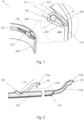
- Fig. 1 shows illumination device 10 for a vehicle headlamp
- the illumination device in the shown example in the figures comprises two light guides 100 comprising a light input section 110 and a light output section 120, wherein the light input section 110 is configured to input light of at least one light source 50 into the light guide 100, wherein the light output section 120 is configured to output light out of the light guide 100.
- the two light guides 100 are better shown in Fig. 2 .
- the light output section 120 of the two light guides 100 follows a first extension line EL1, which is shown in Fig. 1 and Fig. 3 , wherein the light output section 120 in a cross-section orthogonal to the first extension line EL1 substantially corresponds to a circle with a diameter D, which is depicted best in Fig. 3 which shows a cross-sectional A-A view of Fig. 1 .
- the diameter D of the cross sections of the two light guides 100 along the first extension line EL1 is substantially constant. In the shown example, the diameter D of the two light guides 100 is at least 4 mm.
- the light guide input section 110 of the two light guides 100 comprises a light entry surface 110a and a feed section 110b, wherein the light entry surface 110a and the subsequent feed section 110b are configured to couple light of the at least one light source 50 into the light guides 100 and to the light output section 120 of the light guides 100, wherein light fed into the light guide 100 emerges via a light exit region of the light output section 120 by means of coupling-out elements arranged on the light output section 120.
- the illumination device 10 comprises a light radiation body 200 comprising an end region 210 having a free surface 220, wherein the light coupling out of the light output section 120 of the two light guides 100 can be coupled into the light radiation body 200 via the free surface 220.
- the light radiation body 200 further comprises a light radiation surface 230 configured to radiate light coupled into the light radiation body 200 via the free surface 220 out of the light radiation body 200 in front of the illumination device 10.
- the free surface 220 follows a second extension line EL2 substantially parallel to the first extension line EL1, wherein the free surface 220 in a cross-section orthogonal to the second extension line EL2 having a width W, wherein the width W of the free surface 220 is smaller than the diameter D of the light output section 120 of the at least one light guide 100 seen in cross-sections along the first and second extension lines EL1, EL2.
- the at least one light source 50 for each light guide 100 is configured to emit light in the visible wavelength range, wherein the light from the at least one light source 50 can be radiated in front of the illumination device 10 via the light radiation body 200.
- the light radiation body 200 further comprises a light deflection surface opposite to the light radiation surface 230, wherein the light deflection surface comprises a plurality of light deflection elements (not shown in the figures) configured to deflect light emerging onto the light deflection surface to the light radiation surface 230.
- the illumination device 10 further comprises a bundling device 300 configured to bundle and direct the light, which is coupled out from the light output section 120 of the two light guides 100, onto the free surface 220 of the light radiation body 200, so that light which is coupled out of the light output section 120 of the two light guides 100 and would not reach the free surface 220 due to the smaller width W of the free surface 220 compared to the diameter D of the light output section 120 of the at least one light guide 100, is deflected onto the free surface 220.
- a bundling device 300 configured to bundle and direct the light, which is coupled out from the light output section 120 of the two light guides 100, onto the free surface 220 of the light radiation body 200, so that light which is coupled out of the light output section 120 of the two light guides 100 and would not reach the free surface 220 due to the smaller width W of the free surface 220 compared to the diameter D of the light output section 120 of the at least one light guide 100, is deflected onto the free surface 220.
- the bundling device 300 is formed as a shell which encloses the light output section 120 of the at least one light guide 100 on the side opposite the free surface 220 and has end portions 320 tapering towards the free surface 220.
- the bundling device 300 comprises openings 310 (seen in Fig. 1 ) through which the light guides 100 are insertable into the bundling device 300.
- an inner surface of the bundling device 300 is metallized for deflection of light.
- one light guide 100 comprises a light guide end 130, which is formed as a cuboid, in particular a rectangular cuboid.
- the at least two light guides 100 are arranged in a way such that the light guide end 130 of the one light guide 100 is arranged in the light path of the other light guide 100 after the feed section 110b, in order to enable a homogenous light distribution to the free surface 220 of the light radiation body 200.
- Fig. 5 shows a back view of the exemplary illumination device 10.
- Illumination device 10 Light source 50 Light guide 100 Light input section 110 Light entry surface 110a Feed section 110b Light output section 120 Light guide end 130 Light radiation body 200 End region 210 Free surface 220 Light radiation surface 230 Bundling device 300 Opening 310 End portions 320 First extension line EL1 Second extension line EL2 Diameter D Width W
Landscapes
- Engineering & Computer Science (AREA)
- General Engineering & Computer Science (AREA)
- Physics & Mathematics (AREA)
- Optics & Photonics (AREA)
- General Physics & Mathematics (AREA)
- Microelectronics & Electronic Packaging (AREA)
- Geometry (AREA)
- Light Guides In General And Applications Therefor (AREA)
- Non-Portable Lighting Devices Or Systems Thereof (AREA)
Abstract
- at least one light guide (100) comprising a light input section (110) and a light output section (120),
- a light radiation body (200) comprising a free surface (220), wherein the light coupling out of the at least one light guide (100) can be coupled into the light radiation body (200) via the free surface (220),
wherein light from at least one light source (50) can be radiated in front of the illumination device (10) via the light radiation body (200), wherein the illumination device (10) comprises a bundling device (300) configured to bundle and direct the light, which is coupled out from the light output section (120) of the at least one light guide (100), onto the free surface (220) of the light radiation body (200), so that light which is coupled out of the light output section (120) of the at least one light guide (100) and would not reach the free surface (220) due to a smaller width (W) of the free surface (220) compared to a diameter (D) of the light output section (120) of the at least one light guide (100), is deflected onto the free surface (220).
Description
- The invention relates to an illumination device for a vehicle headlamp, the illumination device comprising:
- at least one light guide comprising a light input section and a light output section, wherein the light input section is configured to input light of at least one light source into the light guide, wherein the light output section is configured to output light out of the light guide,
and wherein the light output section of the at least one light guide follows a first extension line, wherein the light output section in a cross-section orthogonal to the first extension line substantially corresponds to a circle with a diameter, - a light radiation body comprising an end region having a free surface, wherein the light coupling out of the light output section of the at least one light guide can be coupled into the light radiation body via the free surface, wherein the light radiation body further comprises a light radiation surface configured to radiate light coupled into the light radiation body via the free surface out of the light radiation body in front of the illumination device,
wherein the free surface follows a second extension line substantially parallel to the first extension line, wherein the free surface in a cross-section orthogonal to the second extension line having a width, wherein the width of the free surface is smaller than the diameter of the light output section of the at least one light guide unit in cross-sections along the first and second extension lines, - at least one light source for emitting light in the visible wavelength range, wherein the light from the at least one light source can be radiated in front of the illumination device via the light radiation body.
- Further, the invention relates to a vehicle headlamp comprising at least one illumination device according to the invention.
- When emitting light via a light radiation body, light must be coupled into the light radiation body as efficiently as possible and distributed as evenly as possible, i.e. light must be coupled in homogeneously.
- It is an object of the invention to provide an enhanced illumination device.
- To achieve this object the illumination device the illumination device comprises a bundling device configured to bundle and direct the light, which is coupled out from the light output section of the at least one light guide, onto the free surface of the light radiation body, so that light which is coupled out of the light output section of the at least one light guide and does not reach the free surface due to the smaller width of the free surface compared to the diameter of the light output section of the at least one light guide, is deflected onto the free surface.
- Advantageously, the diameter of the cross sections of the at least one light guide along the first extension line is substantially constant.
- Advantageously, the diameter of the at least one light guide is at least 4 mm.
- Advantageously, the bundling device is formed as a shell which encloses the light output section of the at least one light guide on the side opposite the free surface and has end portions tapering towards the free surface.
- Advantageously, an inner surface of the bundling device is white or metallized for deflection of light.
- Advantageously, the light guide input section of the at least one light guide comprises a light entry surface and a feed section, wherein the light entry surface and the subsequent feed section are configured to couple light of the at least one light source into the light guide and to the light output section of the light guide, wherein light fed into the light guide emerges via a light exit region of the light output section by means of coupling-out elements arranged on the light output section.
- In particular, the feed section of light guides generally serves to mix the light in order to achieve homogeneous light decoupling from the beginning of the viewing area or the light exit surface of a light guide, whereby the light is not decoupled from the feed section and therefore generally has no decoupling elements.
- Advantageously, the at least one light guide comprises a light guide end, which is formed as a cuboid, in particular a rectangular cuboid.
- Advantageously, the illumination device comprises at least two light guides.
- Advantageously, the at least two light guides are arranged in a way such that the light guide end of one light guide is arranged in the light path of the other light guide after the feed section, in order to enable a homogenous light distribution to the free surface of the light radiation body.
- Advantageously, the bundling device comprises openings through which the at least one light guide is insertable into the bundling device.
- Advantageously, the light radiation body further comprises a light deflection surface opposite to the light radiation surface, wherein the light deflection surface comprises a plurality of light deflection elements configured to deflect light emerging onto the light deflection surface to the light radiation surface.
- Light from the light guide is deflected several times on the inner surface, so the light can be concentrated onto the free surface. Thus, the bundling device acts as a collimator.
- The object of the invention is also achieved by a vehicle headlamp comprising at least one illumination device according to the invention.
- In the following, in order to further demonstrate the present invention, illustrative and non-restrictive embodiments are discussed, as shown in the drawings, which show:
- Fig. 1
- a perspective view of an example of an illumination device according to the invention, wherein the illumination device comprises two light guides, a radiation body with a free surface, and a bundling device configured to deflect light of the light guides onto the free surface;
- Fig. 2
- a front view of the two light guides of the illumination device of
Fig. 1 ; - Fig. 3
- a cross-sectional view of the illumination device of
Fig. 1 along the line A-A; - Fig. 4
- a perspective view of the arrangement of the two light guides to each other, where an end section of one light guide is in the light path of the other light guide in front of a feed section of this light guide; and
- Fig. 5
- a back view of the illumination device of
Fig. 1 . -
Fig. 1 showsillumination device 10 for a vehicle headlamp, the illumination device in the shown example in the figures comprises twolight guides 100 comprising alight input section 110 and alight output section 120, wherein thelight input section 110 is configured to input light of at least onelight source 50 into thelight guide 100, wherein thelight output section 120 is configured to output light out of thelight guide 100. The twolight guides 100 are better shown inFig. 2 . - The
light output section 120 of the twolight guides 100 follows a first extension line EL1, which is shown inFig. 1 andFig. 3 , wherein thelight output section 120 in a cross-section orthogonal to the first extension line EL1 substantially corresponds to a circle with a diameter D, which is depicted best inFig. 3 which shows a cross-sectional A-A view ofFig. 1 . The diameter D of the cross sections of the twolight guides 100 along the first extension line EL1 is substantially constant. In the shown example, the diameter D of the twolight guides 100 is at least 4 mm. - As can be seen in
Fig. 2 , the lightguide input section 110 of the twolight guides 100 comprises alight entry surface 110a and afeed section 110b, wherein thelight entry surface 110a and thesubsequent feed section 110b are configured to couple light of the at least onelight source 50 into thelight guides 100 and to thelight output section 120 of thelight guides 100, wherein light fed into thelight guide 100 emerges via a light exit region of thelight output section 120 by means of coupling-out elements arranged on thelight output section 120. - Further, the
illumination device 10 comprises alight radiation body 200 comprising anend region 210 having afree surface 220, wherein the light coupling out of thelight output section 120 of the twolight guides 100 can be coupled into thelight radiation body 200 via thefree surface 220. - The
light radiation body 200 further comprises alight radiation surface 230 configured to radiate light coupled into thelight radiation body 200 via thefree surface 220 out of thelight radiation body 200 in front of theillumination device 10. - The
free surface 220 follows a second extension line EL2 substantially parallel to the first extension line EL1, wherein thefree surface 220 in a cross-section orthogonal to the second extension line EL2 having a width W, wherein the width W of thefree surface 220 is smaller than the diameter D of thelight output section 120 of the at least onelight guide 100 seen in cross-sections along the first and second extension lines EL1, EL2. - The at least one
light source 50 for eachlight guide 100 is configured to emit light in the visible wavelength range, wherein the light from the at least onelight source 50 can be radiated in front of theillumination device 10 via thelight radiation body 200. - The
light radiation body 200 further comprises a light deflection surface opposite to thelight radiation surface 230, wherein the light deflection surface comprises a plurality of light deflection elements (not shown in the figures) configured to deflect light emerging onto the light deflection surface to thelight radiation surface 230. - The
illumination device 10 further comprises abundling device 300 configured to bundle and direct the light, which is coupled out from thelight output section 120 of the twolight guides 100, onto thefree surface 220 of thelight radiation body 200, so that light which is coupled out of thelight output section 120 of the twolight guides 100 and would not reach thefree surface 220 due to the smaller width W of thefree surface 220 compared to the diameter D of thelight output section 120 of the at least onelight guide 100, is deflected onto thefree surface 220. - As can be seen for example in
Fig. 1 and Fig. 2 , thebundling device 300 is formed as a shell which encloses thelight output section 120 of the at least onelight guide 100 on the side opposite thefree surface 220 and hasend portions 320 tapering towards thefree surface 220. - Further, the
bundling device 300 comprises openings 310 (seen inFig. 1 ) through which thelight guides 100 are insertable into thebundling device 300. - In the shown example in the figures, an inner surface of the
bundling device 300 is metallized for deflection of light. - As can be seen in
Fig. 4 , onelight guide 100 comprises alight guide end 130, which is formed as a cuboid, in particular a rectangular cuboid. - The at least two
light guides 100 are arranged in a way such that the light guide end 130 of the onelight guide 100 is arranged in the light path of theother light guide 100 after thefeed section 110b, in order to enable a homogenous light distribution to thefree surface 220 of thelight radiation body 200. - Further,
Fig. 5 shows a back view of theexemplary illumination device 10. -
Illumination device 10 Light source 50 Light guide 100 Light input section 110 Light entry surface 110a Feed section 110b Light output section 120 Light guide end 130 Light radiation body 200 End region 210 Free surface 220 Light radiation surface 230 Bundling device 300 Opening 310 End portions 320 First extension line EL1 Second extension line EL2 Diameter D Width W
Claims (12)
- Illumination device (10) for a vehicle headlamp, the illumination device comprising:- at least one light guide (100) comprising a light input section (110) and a light output section (120), wherein the light input section (110) is configured to input light of at least one light source (50) into the light guide (100), wherein the light output section (120) is configured to output light out of the light guide (100),
and wherein the light output section (120) of the at least one light guide (100) follows a first extension line (EL1), wherein the light output section (120) in a cross-section orthogonal to the first extension line (EL1) substantially corresponds to a circle with a diameter (D),- a light radiation body (200) comprising an end region (210) having a free surface (220), wherein the light coupling out of the light output section (120) of the at least one light guide (100) can be coupled into the light radiation body (200) via the free surface (220), wherein the light radiation body (200) further comprises a light radiation surface (230) configured to radiate light coupled into the light radiation body (200) via the free surface (220) out of the light radiation body (200) in front of the illumination device (10),
wherein the free surface (220) follows a second extension line (EL2) substantially parallel to the first extension line (EL1), wherein the free surface (220) in a cross-section orthogonal to the second extension line (EL2) having a width (W), wherein the width (W) of the free surface (220) is smaller than the diameter (D) of the light output section (120) of the at least one light guide (100) seen in cross-sections along the first and second extension lines (EL1, EL2),- at least one light source (50) for emitting light in the visible wavelength range, wherein the light from the at least one light source (50) can be radiated in front of the illumination device (10) via the light radiation body (200),
characterized in that
the illumination device (10) comprises a bundling device (300) configured to bundle and direct the light, which is coupled out from the light output section (120) of the at least one light guide (100), onto the free surface (220) of the light radiation body (200), so that light which is coupled out of the light output section (120) of the at least one light guide (100) and would not reach the free surface (220) due to the smaller width (W) of the free surface (220) compared to the diameter (D) of the light output section (120) of the at least one light guide (100), is deflected onto the free surface (220). - Illumination device according to claim 1, wherein the diameter (D) of the cross sections of the at least one light guide (100) along the first extension line (EL1) is substantially constant.
- Illumination device according to claim 1 or 2, wherein the diameter (D) of the at least one light guide (100) is at least 4 mm.
- Illumination device according to one of claims 1 to 3, wherein the bundling device (300) is formed as a shell which encloses the light output section (120) of the at least one light guide (100) on the side opposite the free surface (220) and has end portions (320) tapering towards the free surface (220).
- Illumination device according to claim 4, wherein an inner surface of the bundling device (300) is white or metallized for deflection of light.
- Illumination device according to any of claims 1 to 5, wherein the light guide input section (110) of the at least one light guide (100) comprises a light entry surface (110a) and a feed section (110b), wherein the light entry surface (110a) and the subsequent feed section (110b) are configured to couple light of the at least one light source (50) into the light guide (100) and to the light output section (120) of the light guide (100), wherein light fed into the light guide (100) emerges via a light exit region of the light output section (120) by means of coupling-out elements arranged on the light output section (120).
- Illumination device according to any of claims 1 to 6, wherein the at least one light guide (100) comprises a light guide end (130), which is formed as a cuboid, in particular a rectangular cuboid.
- Illumination device according to any one of claims 1 to 7, wherein the illumination device (10) comprises at least two light guides (100).
- Illumination device according to claim 8, wherein the at least two light guides (100) are arranged in a way such that the light guide end (130) of one light guide (100) is arranged in the light path of the other light guide (100) after the feed section (110b), in order to enable a homogenous light distribution to the free surface (220) of the light radiation body (200).
- Illumination device according to any one of claims 1 to 9, wherein the bundling device (300) comprises openings (310) through which the at least one light guide (100) is insertable into the bundling device (300).
- Illumination device according to any one of claims 1 to 10, wherein the light radiation body (200) further comprises a light deflection surface opposite to the light radiation surface (230), wherein the light deflection surface comprises a plurality of light deflection elements configured to deflect light emerging onto the light deflection surface to the light radiation surface (230).
- Vehicle headlamp comprising at least one illumination device (10) according to any of claims 1 to 11.
Priority Applications (3)
| Application Number | Priority Date | Filing Date | Title |
|---|---|---|---|
| EP23164082.2A EP4435318B1 (en) | 2023-03-24 | 2023-03-24 | Illumination device for a vehicle |
| CN202410325806.1A CN118687104A (en) | 2023-03-24 | 2024-03-21 | Lighting device for vehicles |
| KR1020240039696A KR20240143967A (en) | 2023-03-24 | 2024-03-22 | Illumination device for a vehicle |
Applications Claiming Priority (1)
| Application Number | Priority Date | Filing Date | Title |
|---|---|---|---|
| EP23164082.2A EP4435318B1 (en) | 2023-03-24 | 2023-03-24 | Illumination device for a vehicle |
Publications (2)
| Publication Number | Publication Date |
|---|---|
| EP4435318A1 true EP4435318A1 (en) | 2024-09-25 |
| EP4435318B1 EP4435318B1 (en) | 2025-11-26 |
Family
ID=85726184
Family Applications (1)
| Application Number | Title | Priority Date | Filing Date |
|---|---|---|---|
| EP23164082.2A Active EP4435318B1 (en) | 2023-03-24 | 2023-03-24 | Illumination device for a vehicle |
Country Status (3)
| Country | Link |
|---|---|
| EP (1) | EP4435318B1 (en) |
| KR (1) | KR20240143967A (en) |
| CN (1) | CN118687104A (en) |
Citations (7)
| Publication number | Priority date | Publication date | Assignee | Title |
|---|---|---|---|---|
| WO2015071620A1 (en) * | 2013-11-18 | 2015-05-21 | Automotive Lighting Rear Lamps France | Lighting and/or signalling system with light guides for a vehicle |
| EP3112215A1 (en) * | 2015-06-29 | 2017-01-04 | ZKW Group GmbH | Light guidance device for creating at least one illumination function and/or signaling function of a head lamp of a vehicle |
| JP2018006226A (en) * | 2016-07-06 | 2018-01-11 | 株式会社小糸製作所 | Lamp |
| DE102017114476A1 (en) * | 2017-06-29 | 2019-01-03 | Automotive Lighting Reutlingen Gmbh | Lighting device of a motor vehicle |
| JP2020095782A (en) * | 2018-12-10 | 2020-06-18 | 株式会社小糸製作所 | Vehicular lighting fixture |
| WO2021005331A1 (en) * | 2019-07-11 | 2021-01-14 | Dyson Technology Limited | Vehicle lamp assembly |
| CN113175651A (en) * | 2021-04-22 | 2021-07-27 | 华域视觉科技(上海)有限公司 | Light guide structure, light emitting device and vehicle |
-
2023
- 2023-03-24 EP EP23164082.2A patent/EP4435318B1/en active Active
-
2024
- 2024-03-21 CN CN202410325806.1A patent/CN118687104A/en active Pending
- 2024-03-22 KR KR1020240039696A patent/KR20240143967A/en not_active Ceased
Patent Citations (7)
| Publication number | Priority date | Publication date | Assignee | Title |
|---|---|---|---|---|
| WO2015071620A1 (en) * | 2013-11-18 | 2015-05-21 | Automotive Lighting Rear Lamps France | Lighting and/or signalling system with light guides for a vehicle |
| EP3112215A1 (en) * | 2015-06-29 | 2017-01-04 | ZKW Group GmbH | Light guidance device for creating at least one illumination function and/or signaling function of a head lamp of a vehicle |
| JP2018006226A (en) * | 2016-07-06 | 2018-01-11 | 株式会社小糸製作所 | Lamp |
| DE102017114476A1 (en) * | 2017-06-29 | 2019-01-03 | Automotive Lighting Reutlingen Gmbh | Lighting device of a motor vehicle |
| JP2020095782A (en) * | 2018-12-10 | 2020-06-18 | 株式会社小糸製作所 | Vehicular lighting fixture |
| WO2021005331A1 (en) * | 2019-07-11 | 2021-01-14 | Dyson Technology Limited | Vehicle lamp assembly |
| CN113175651A (en) * | 2021-04-22 | 2021-07-27 | 华域视觉科技(上海)有限公司 | Light guide structure, light emitting device and vehicle |
Also Published As
| Publication number | Publication date |
|---|---|
| KR20240143967A (en) | 2024-10-02 |
| CN118687104A (en) | 2024-09-24 |
| EP4435318B1 (en) | 2025-11-26 |
Similar Documents
| Publication | Publication Date | Title |
|---|---|---|
| EP2074935B1 (en) | Illumination device for producing light for endoscopy or microscopy | |
| US20230091765A1 (en) | Motor Vehicle | |
| DE102013212353B4 (en) | Motor vehicle lighting device with a light guide arrangement having coupling optics and transport and shaping optics | |
| US20190128492A1 (en) | Light Guiding Optical System | |
| WO2008077338A1 (en) | Light-emitting devices and lens therefor | |
| US11572994B2 (en) | Homogeneous light emission and light guide arrangement of an automobile vehicle for a uniform lit appearance | |
| DE102013104176A1 (en) | Lighting device for vehicles | |
| EP4435318B1 (en) | Illumination device for a vehicle | |
| WO2014180813A1 (en) | Lighting device for vehicles | |
| DE102022209714A1 (en) | Lighting device and display | |
| DE202021106229U1 (en) | Signal lighting device or lighting device for a motor vehicle headlight | |
| EP1152188A2 (en) | Lighting assembly and method of operating the same | |
| DE102013110344B4 (en) | Lighting device for vehicles for generating tail light and rear fog light functions | |
| US11629837B2 (en) | Lighting arrangement for vehicles | |
| EP1832902A1 (en) | Flat lamp device | |
| DE102022110370A1 (en) | Optical element and lamp equipped with it | |
| DE102015210372B4 (en) | Signal light module for a motor vehicle | |
| DE102019211799B4 (en) | Device for generating a light distribution for a vehicle | |
| JP2017220412A (en) | Lamp | |
| US20180118104A1 (en) | Bent light guide | |
| EP4419835B1 (en) | Lighting device for a motor vehicle | |
| US12510221B2 (en) | Signal light or illumination device with multi-section light guiding body | |
| JP2003521732A (en) | Optical coupling system | |
| CN210894948U (en) | Illumination assembly and image forming apparatus | |
| EP3795895A1 (en) | Modular light extraction unit for producing uniform luminance |
Legal Events
| Date | Code | Title | Description |
|---|---|---|---|
| PUAI | Public reference made under article 153(3) epc to a published international application that has entered the european phase |
Free format text: ORIGINAL CODE: 0009012 |
|
| STAA | Information on the status of an ep patent application or granted ep patent |
Free format text: STATUS: THE APPLICATION HAS BEEN PUBLISHED |
|
| AK | Designated contracting states |
Kind code of ref document: A1 Designated state(s): AL AT BE BG CH CY CZ DE DK EE ES FI FR GB GR HR HU IE IS IT LI LT LU LV MC ME MK MT NL NO PL PT RO RS SE SI SK SM TR |
|
| STAA | Information on the status of an ep patent application or granted ep patent |
Free format text: STATUS: REQUEST FOR EXAMINATION WAS MADE |
|
| 17P | Request for examination filed |
Effective date: 20250305 |
|
| GRAP | Despatch of communication of intention to grant a patent |
Free format text: ORIGINAL CODE: EPIDOSNIGR1 |
|
| STAA | Information on the status of an ep patent application or granted ep patent |
Free format text: STATUS: GRANT OF PATENT IS INTENDED |
|
| RIC1 | Information provided on ipc code assigned before grant |
Ipc: F21S 41/24 20180101AFI20250901BHEP Ipc: F21S 41/32 20180101ALI20250901BHEP Ipc: F21S 41/141 20180101ALI20250901BHEP Ipc: F21S 43/237 20180101ALI20250901BHEP Ipc: F21S 43/239 20180101ALI20250901BHEP Ipc: F21S 43/245 20180101ALI20250901BHEP Ipc: F21S 43/247 20180101ALI20250901BHEP Ipc: F21S 43/251 20180101ALI20250901BHEP Ipc: F21S 43/31 20180101ALI20250901BHEP Ipc: F21S 43/40 20180101ALI20250901BHEP |
|
| GRAS | Grant fee paid |
Free format text: ORIGINAL CODE: EPIDOSNIGR3 |
|
| GRAA | (expected) grant |
Free format text: ORIGINAL CODE: 0009210 |
|
| STAA | Information on the status of an ep patent application or granted ep patent |
Free format text: STATUS: THE PATENT HAS BEEN GRANTED |
|
| INTG | Intention to grant announced |
Effective date: 20250925 |
|
| AK | Designated contracting states |
Kind code of ref document: B1 Designated state(s): AL AT BE BG CH CY CZ DE DK EE ES FI FR GB GR HR HU IE IS IT LI LT LU LV MC ME MK MT NL NO PL PT RO RS SE SI SK SM TR |
|
| REG | Reference to a national code |
Ref country code: CH Ref legal event code: F10 Free format text: ST27 STATUS EVENT CODE: U-0-0-F10-F00 (AS PROVIDED BY THE NATIONAL OFFICE) Effective date: 20251126 Ref country code: GB Ref legal event code: FG4D |
|
| REG | Reference to a national code |
Ref country code: DE Ref legal event code: R096 Ref document number: 602023008880 Country of ref document: DE |
|
| REG | Reference to a national code |
Ref country code: IE Ref legal event code: FG4D |
|
| REG | Reference to a national code |
Ref country code: NL Ref legal event code: MP Effective date: 20251126 |
|
| PG25 | Lapsed in a contracting state [announced via postgrant information from national office to epo] |
Ref country code: ES Free format text: LAPSE BECAUSE OF FAILURE TO SUBMIT A TRANSLATION OF THE DESCRIPTION OR TO PAY THE FEE WITHIN THE PRESCRIBED TIME-LIMIT Effective date: 20251126 |
|
| REG | Reference to a national code |
Ref country code: LT Ref legal event code: MG9D |
|
| PG25 | Lapsed in a contracting state [announced via postgrant information from national office to epo] |
Ref country code: NO Free format text: LAPSE BECAUSE OF FAILURE TO SUBMIT A TRANSLATION OF THE DESCRIPTION OR TO PAY THE FEE WITHIN THE PRESCRIBED TIME-LIMIT Effective date: 20260226 |
|
| PGFP | Annual fee paid to national office [announced via postgrant information from national office to epo] |
Ref country code: DE Payment date: 20260320 Year of fee payment: 4 |
|
| PG25 | Lapsed in a contracting state [announced via postgrant information from national office to epo] |
Ref country code: FI Free format text: LAPSE BECAUSE OF FAILURE TO SUBMIT A TRANSLATION OF THE DESCRIPTION OR TO PAY THE FEE WITHIN THE PRESCRIBED TIME-LIMIT Effective date: 20251126 Ref country code: HR Free format text: LAPSE BECAUSE OF FAILURE TO SUBMIT A TRANSLATION OF THE DESCRIPTION OR TO PAY THE FEE WITHIN THE PRESCRIBED TIME-LIMIT Effective date: 20251126 Ref country code: AT Free format text: LAPSE BECAUSE OF FAILURE TO SUBMIT A TRANSLATION OF THE DESCRIPTION OR TO PAY THE FEE WITHIN THE PRESCRIBED TIME-LIMIT Effective date: 20251126 |
|
| PGFP | Annual fee paid to national office [announced via postgrant information from national office to epo] |
Ref country code: AT Payment date: 20260301 Year of fee payment: 4 |
|
| REG | Reference to a national code |
Ref country code: AT Ref legal event code: MK05 Ref document number: 1861372 Country of ref document: AT Kind code of ref document: T Effective date: 20251126 |
|
| PG25 | Lapsed in a contracting state [announced via postgrant information from national office to epo] |
Ref country code: NL Free format text: LAPSE BECAUSE OF FAILURE TO SUBMIT A TRANSLATION OF THE DESCRIPTION OR TO PAY THE FEE WITHIN THE PRESCRIBED TIME-LIMIT Effective date: 20251126 |
|
| PG25 | Lapsed in a contracting state [announced via postgrant information from national office to epo] |
Ref country code: RS Free format text: LAPSE BECAUSE OF FAILURE TO SUBMIT A TRANSLATION OF THE DESCRIPTION OR TO PAY THE FEE WITHIN THE PRESCRIBED TIME-LIMIT Effective date: 20260226 |
|
| PG25 | Lapsed in a contracting state [announced via postgrant information from national office to epo] |
Ref country code: IS Free format text: LAPSE BECAUSE OF FAILURE TO SUBMIT A TRANSLATION OF THE DESCRIPTION OR TO PAY THE FEE WITHIN THE PRESCRIBED TIME-LIMIT Effective date: 20260326 |
|
| PGFP | Annual fee paid to national office [announced via postgrant information from national office to epo] |
Ref country code: FR Payment date: 20260324 Year of fee payment: 4 |
|
| P01 | Opt-out of the competence of the unified patent court (upc) registered |
Free format text: CASE NUMBER: UPC_APP_0009678_4435318/2026 Effective date: 20260312 |
|
| PG25 | Lapsed in a contracting state [announced via postgrant information from national office to epo] |
Ref country code: PT Free format text: LAPSE BECAUSE OF FAILURE TO SUBMIT A TRANSLATION OF THE DESCRIPTION OR TO PAY THE FEE WITHIN THE PRESCRIBED TIME-LIMIT Effective date: 20260326 |
|
| PG25 | Lapsed in a contracting state [announced via postgrant information from national office to epo] |
Ref country code: PL Free format text: LAPSE BECAUSE OF FAILURE TO SUBMIT A TRANSLATION OF THE DESCRIPTION OR TO PAY THE FEE WITHIN THE PRESCRIBED TIME-LIMIT Effective date: 20251126 |
|
| PG25 | Lapsed in a contracting state [announced via postgrant information from national office to epo] |
Ref country code: LV Free format text: LAPSE BECAUSE OF FAILURE TO SUBMIT A TRANSLATION OF THE DESCRIPTION OR TO PAY THE FEE WITHIN THE PRESCRIBED TIME-LIMIT Effective date: 20251126 |
|
| PG25 | Lapsed in a contracting state [announced via postgrant information from national office to epo] |
Ref country code: BG Free format text: LAPSE BECAUSE OF FAILURE TO SUBMIT A TRANSLATION OF THE DESCRIPTION OR TO PAY THE FEE WITHIN THE PRESCRIBED TIME-LIMIT Effective date: 20251126 |
|
| PG25 | Lapsed in a contracting state [announced via postgrant information from national office to epo] |
Ref country code: LT Free format text: LAPSE BECAUSE OF FAILURE TO SUBMIT A TRANSLATION OF THE DESCRIPTION OR TO PAY THE FEE WITHIN THE PRESCRIBED TIME-LIMIT Effective date: 20251126 |
|
| PG25 | Lapsed in a contracting state [announced via postgrant information from national office to epo] |
Ref country code: SM Free format text: LAPSE BECAUSE OF FAILURE TO SUBMIT A TRANSLATION OF THE DESCRIPTION OR TO PAY THE FEE WITHIN THE PRESCRIBED TIME-LIMIT Effective date: 20251126 |
|
| PG25 | Lapsed in a contracting state [announced via postgrant information from national office to epo] |
Ref country code: DK Free format text: LAPSE BECAUSE OF FAILURE TO SUBMIT A TRANSLATION OF THE DESCRIPTION OR TO PAY THE FEE WITHIN THE PRESCRIBED TIME-LIMIT Effective date: 20251126 |
|
| PG25 | Lapsed in a contracting state [announced via postgrant information from national office to epo] |
Ref country code: IT Free format text: LAPSE BECAUSE OF FAILURE TO SUBMIT A TRANSLATION OF THE DESCRIPTION OR TO PAY THE FEE WITHIN THE PRESCRIBED TIME-LIMIT Effective date: 20251126 |
|
| PG25 | Lapsed in a contracting state [announced via postgrant information from national office to epo] |
Ref country code: EE Free format text: LAPSE BECAUSE OF FAILURE TO SUBMIT A TRANSLATION OF THE DESCRIPTION OR TO PAY THE FEE WITHIN THE PRESCRIBED TIME-LIMIT Effective date: 20251126 |
|
| PG25 | Lapsed in a contracting state [announced via postgrant information from national office to epo] |
Ref country code: CZ Free format text: LAPSE BECAUSE OF FAILURE TO SUBMIT A TRANSLATION OF THE DESCRIPTION OR TO PAY THE FEE WITHIN THE PRESCRIBED TIME-LIMIT Effective date: 20251126 |
|
| PG25 | Lapsed in a contracting state [announced via postgrant information from national office to epo] |
Ref country code: SK Free format text: LAPSE BECAUSE OF FAILURE TO SUBMIT A TRANSLATION OF THE DESCRIPTION OR TO PAY THE FEE WITHIN THE PRESCRIBED TIME-LIMIT Effective date: 20251126 |
|
| PG25 | Lapsed in a contracting state [announced via postgrant information from national office to epo] |
Ref country code: SE Free format text: LAPSE BECAUSE OF FAILURE TO SUBMIT A TRANSLATION OF THE DESCRIPTION OR TO PAY THE FEE WITHIN THE PRESCRIBED TIME-LIMIT Effective date: 20251126 |