EP2074935B1 - Illumination device for producing light for endoscopy or microscopy - Google Patents
Illumination device for producing light for endoscopy or microscopy Download PDFInfo
- Publication number
- EP2074935B1 EP2074935B1 EP08171287A EP08171287A EP2074935B1 EP 2074935 B1 EP2074935 B1 EP 2074935B1 EP 08171287 A EP08171287 A EP 08171287A EP 08171287 A EP08171287 A EP 08171287A EP 2074935 B1 EP2074935 B1 EP 2074935B1
- Authority
- EP
- European Patent Office
- Prior art keywords
- light
- light source
- illumination device
- cooling element
- optical waveguide
- Prior art date
- Legal status (The legal status is an assumption and is not a legal conclusion. Google has not performed a legal analysis and makes no representation as to the accuracy of the status listed.)
- Active
Links
- 238000005286 illumination Methods 0.000 title claims description 39
- 238000001839 endoscopy Methods 0.000 title claims description 5
- 238000000386 microscopy Methods 0.000 title claims description 5
- 238000001816 cooling Methods 0.000 claims description 114
- 230000003287 optical effect Effects 0.000 claims description 53
- 238000009792 diffusion process Methods 0.000 claims description 17
- 230000008878 coupling Effects 0.000 claims description 15
- 238000010168 coupling process Methods 0.000 claims description 15
- 238000005859 coupling reaction Methods 0.000 claims description 15
- 239000007788 liquid Substances 0.000 claims description 14
- 238000010521 absorption reaction Methods 0.000 claims description 6
- 239000011248 coating agent Substances 0.000 claims description 6
- 238000000576 coating method Methods 0.000 claims description 6
- 239000007787 solid Substances 0.000 claims description 3
- 239000000806 elastomer Substances 0.000 claims description 2
- 229920001971 elastomer Polymers 0.000 claims description 2
- 239000013307 optical fiber Substances 0.000 description 120
- 239000000835 fiber Substances 0.000 description 15
- 230000000694 effects Effects 0.000 description 10
- 239000000463 material Substances 0.000 description 8
- 239000000758 substrate Substances 0.000 description 8
- 238000004519 manufacturing process Methods 0.000 description 6
- 230000008901 benefit Effects 0.000 description 5
- 230000017525 heat dissipation Effects 0.000 description 5
- 239000002184 metal Substances 0.000 description 5
- 229910052751 metal Inorganic materials 0.000 description 5
- 241000219739 Lens Species 0.000 description 4
- 239000000853 adhesive Substances 0.000 description 4
- 238000004026 adhesive bonding Methods 0.000 description 4
- 230000001070 adhesive effect Effects 0.000 description 4
- 230000002411 adverse Effects 0.000 description 4
- 239000004020 conductor Substances 0.000 description 4
- 238000002844 melting Methods 0.000 description 4
- 230000008018 melting Effects 0.000 description 4
- 229910000679 solder Inorganic materials 0.000 description 4
- 229910003460 diamond Inorganic materials 0.000 description 3
- 239000010432 diamond Substances 0.000 description 3
- OAICVXFJPJFONN-UHFFFAOYSA-N Phosphorus Chemical compound [P] OAICVXFJPJFONN-UHFFFAOYSA-N 0.000 description 2
- 238000009825 accumulation Methods 0.000 description 2
- 230000005540 biological transmission Effects 0.000 description 2
- 238000010586 diagram Methods 0.000 description 2
- 239000011521 glass Substances 0.000 description 2
- 238000010438 heat treatment Methods 0.000 description 2
- 229910001507 metal halide Inorganic materials 0.000 description 2
- 150000005309 metal halides Chemical class 0.000 description 2
- 230000009467 reduction Effects 0.000 description 2
- 229910052594 sapphire Inorganic materials 0.000 description 2
- 239000010980 sapphire Substances 0.000 description 2
- 238000012935 Averaging Methods 0.000 description 1
- RYGMFSIKBFXOCR-UHFFFAOYSA-N Copper Chemical compound [Cu] RYGMFSIKBFXOCR-UHFFFAOYSA-N 0.000 description 1
- 240000004322 Lens culinaris Species 0.000 description 1
- 230000003667 anti-reflective effect Effects 0.000 description 1
- 230000008859 change Effects 0.000 description 1
- 238000010276 construction Methods 0.000 description 1
- 229910052802 copper Inorganic materials 0.000 description 1
- 239000010949 copper Substances 0.000 description 1
- 238000007599 discharging Methods 0.000 description 1
- 238000000605 extraction Methods 0.000 description 1
- 239000003365 glass fiber Substances 0.000 description 1
- 230000001788 irregular Effects 0.000 description 1
- 238000005304 joining Methods 0.000 description 1
- 238000000034 method Methods 0.000 description 1
- 230000010287 polarization Effects 0.000 description 1
- 238000003825 pressing Methods 0.000 description 1
- 230000001737 promoting effect Effects 0.000 description 1
- 125000006850 spacer group Chemical group 0.000 description 1
- 230000007704 transition Effects 0.000 description 1
- 239000012780 transparent material Substances 0.000 description 1
Images


Classifications
-
- A—HUMAN NECESSITIES
- A61—MEDICAL OR VETERINARY SCIENCE; HYGIENE
- A61B—DIAGNOSIS; SURGERY; IDENTIFICATION
- A61B1/00—Instruments for performing medical examinations of the interior of cavities or tubes of the body by visual or photographical inspection, e.g. endoscopes; Illuminating arrangements therefor
- A61B1/06—Instruments for performing medical examinations of the interior of cavities or tubes of the body by visual or photographical inspection, e.g. endoscopes; Illuminating arrangements therefor with illuminating arrangements
- A61B1/07—Instruments for performing medical examinations of the interior of cavities or tubes of the body by visual or photographical inspection, e.g. endoscopes; Illuminating arrangements therefor with illuminating arrangements using light-conductive means, e.g. optical fibres
-
- A—HUMAN NECESSITIES
- A61—MEDICAL OR VETERINARY SCIENCE; HYGIENE
- A61B—DIAGNOSIS; SURGERY; IDENTIFICATION
- A61B1/00—Instruments for performing medical examinations of the interior of cavities or tubes of the body by visual or photographical inspection, e.g. endoscopes; Illuminating arrangements therefor
- A61B1/06—Instruments for performing medical examinations of the interior of cavities or tubes of the body by visual or photographical inspection, e.g. endoscopes; Illuminating arrangements therefor with illuminating arrangements
- A61B1/0661—Endoscope light sources
- A61B1/0669—Endoscope light sources at proximal end of an endoscope
-
- A—HUMAN NECESSITIES
- A61—MEDICAL OR VETERINARY SCIENCE; HYGIENE
- A61B—DIAGNOSIS; SURGERY; IDENTIFICATION
- A61B1/00—Instruments for performing medical examinations of the interior of cavities or tubes of the body by visual or photographical inspection, e.g. endoscopes; Illuminating arrangements therefor
- A61B1/06—Instruments for performing medical examinations of the interior of cavities or tubes of the body by visual or photographical inspection, e.g. endoscopes; Illuminating arrangements therefor with illuminating arrangements
- A61B1/0661—Endoscope light sources
- A61B1/0684—Endoscope light sources using light emitting diodes [LED]
-
- A—HUMAN NECESSITIES
- A61—MEDICAL OR VETERINARY SCIENCE; HYGIENE
- A61B—DIAGNOSIS; SURGERY; IDENTIFICATION
- A61B1/00—Instruments for performing medical examinations of the interior of cavities or tubes of the body by visual or photographical inspection, e.g. endoscopes; Illuminating arrangements therefor
- A61B1/12—Instruments for performing medical examinations of the interior of cavities or tubes of the body by visual or photographical inspection, e.g. endoscopes; Illuminating arrangements therefor with cooling or rinsing arrangements
- A61B1/128—Instruments for performing medical examinations of the interior of cavities or tubes of the body by visual or photographical inspection, e.g. endoscopes; Illuminating arrangements therefor with cooling or rinsing arrangements provided with means for regulating temperature
-
- G—PHYSICS
- G02—OPTICS
- G02B—OPTICAL ELEMENTS, SYSTEMS OR APPARATUS
- G02B23/00—Telescopes, e.g. binoculars; Periscopes; Instruments for viewing the inside of hollow bodies; Viewfinders; Optical aiming or sighting devices
- G02B23/24—Instruments or systems for viewing the inside of hollow bodies, e.g. fibrescopes
- G02B23/2407—Optical details
- G02B23/2461—Illumination
- G02B23/2469—Illumination using optical fibres
-
- G—PHYSICS
- G02—OPTICS
- G02B—OPTICAL ELEMENTS, SYSTEMS OR APPARATUS
- G02B6/00—Light guides; Structural details of arrangements comprising light guides and other optical elements, e.g. couplings
- G02B6/24—Coupling light guides
- G02B6/42—Coupling light guides with opto-electronic elements
- G02B6/4201—Packages, e.g. shape, construction, internal or external details
- G02B6/4249—Packages, e.g. shape, construction, internal or external details comprising arrays of active devices and fibres
-
- G—PHYSICS
- G02—OPTICS
- G02B—OPTICAL ELEMENTS, SYSTEMS OR APPARATUS
- G02B6/00—Light guides; Structural details of arrangements comprising light guides and other optical elements, e.g. couplings
- G02B6/24—Coupling light guides
- G02B6/42—Coupling light guides with opto-electronic elements
- G02B6/4298—Coupling light guides with opto-electronic elements coupling with non-coherent light sources and/or radiation detectors, e.g. lamps, incandescent bulbs, scintillation chambers
Definitions
- the invention relates to a lighting device for generating light and for coupling the light into a proximal end of a light guide of an observation device for endoscopy or microscopy or in the observation device itself, with a light source having at least one LED, with at least one light guide for guiding the of Light source radiated light to a proximal end of the light guide cable or to the observation device, wherein the proximal end of the light guide is disposed on a side facing the light guide side of the light source, and with a cooling device for discharging heat generated by the light source, wherein the cooling device comprises at least a first cooling element for dissipating the heat generated by the light source, which is arranged on a side of the light source facing away from the proximal end of the light guide.
- WO 98/08123 A discloses an apparatus and method for coupling high intensity light into a low melting temperature optical fiber, wherein a high melting temperature, certain numerical aperture optical fiber is used as a spatial filter between the high intensity light source and the low melting temperature optical fiber.
- the spatial filter dissipates undirected modes of light transmission before entering the low melting temperature optical fiber.
- the spatial filter is surrounded by a heat sink through which the light guide forming the spatial filter is passed.
- a lighting device which is integrated in an endoscope.
- the light source of this illumination device comprises an array of LEDs which are arranged on a heat-conducting substrate.
- the LEDs are cooled on the backside via a heat sink.
- the LED's is directly the proximal end of a light guide.
- the illumination device has a first cooling element on a side of the light source facing away from the proximal end of the light guide, so that the heat generated by the light source can be dissipated to the rear of the light source.
- the illumination device further has an additional second cooling element on the side of the light source facing the proximal end of the light guide, through which the proximal end of the light guide passes.
- the heat which is emitted via the light-radiating surface of the LED is absorbed and removed by the second cooling element.
- the light guide is acted upon by the heat generated by the light source is, also cooled because it emits the absorbed heat to the second cooling element via its outer surface.
- the cooling concept according to the invention is therefore particularly efficient, as a result of which the light source and the light guide are advantageously sufficiently cooled and the lighting device retains its functionality despite heating.
- optical fibers extend through the second cooling element, wherein the optical fibers are arranged at a distance from one another in the region of the second cooling element.
- the light guides are distributed over the entire LED surface, so that the entire light emitted by the LED light is used independently of the light emission intensity of the individual areas.
- the selection of the arranged at the areas of high light emission light guide for light transport to the observation device also provides in comparison to a use of all optical fibers for light intensity provision a higher average maximum light intensity for the lighting device.
- the light guides, which are arranged at the areas of low or medium light emission can be used, for example, for effect lighting of the front panel or for displaying the operating state of the lighting device. This measure has the advantage that the entire light emitted by the LED light is used effectively.
- the arrangement of the light guide can be performed on the LED by machine, since the light guides to be arranged, for example, can be regularly distributed over the LED surface mounted.
- the first cooling element and the second cooling element are thermally conductively connected.
- the light source has a plurality of LEDs.
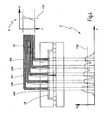
- Fig. 1 an illumination device provided with the general reference numeral 10 is shown.
- the cooling body 32 can likewise be arranged on the side of the LED 18 facing the proximal ends 22 of the light guides 24 or also spaced from the cooling elements 28, 30.
- the first and second cooling elements 28, 30 and the cooling body 32 are further thermally conductively connected to each other.
- the first cooling element 28 is connected by means of solder drops 34 and thermally conductive adhesive 36 with an end facing the first cooling element 28 end of the heat sink 32, and the second cooling element 30 is further glued in its edge region by means of the heat-conductive adhesive 36 to the cooling device 26.
- the heat generated by the LED 18 is consequently dissipated in the direction of arrows 40a, b to the second or first cooling element 30, 28.
- the proximal ends 22 of the optical fiber bundles 38a-e are disposed directly on the light-emitting surface 20 of the LED 18.
- a direct arrangement of the optical fiber bundles 38a-e on the LED 18 means an arrangement without additional optical elements in the form of lenses, fiber clusters, etc.
- the proximal ends 22 of the optical fibers 24 of the optical fiber bundles 38a-e may, for example, be arranged directly on the light-radiating surface 20 of the LED 18 or also be slightly spaced therefrom.
- the direct arrangement of the optical fiber bundles 38a-e at the areas of high light emission 44a-e can be realized, for example, by pressing or gluing.
- ⁇ denotes the angle between a longitudinal direction X of the optical fiber bundle 38, which is arranged on a surface 20 of the LED 18 and in which the light is to be coupled, and the light propagation direction. If the optical fiber bundle 38 is arranged directly on or slightly spaced from the surface 20 of the LED 18, the entire emitted light is coupled into the optical fiber bundle 38 independently of the light propagation direction. This additionally increases the maximum light intensity of the lighting device 10.
- the proximal end 22 of the optical fibers 24 of the optical fiber bundle 38b preferably an anti-reflection coating 60, which additionally increases the light intensity of the light, which is coupled into the proximal ends 22 of the optical fibers 24 of the optical fiber bundle 38b.
- a light modulation layer 62 is further arranged, which can change a property of the light generated by the LED 18, here a light wavelength.
- the light modulation layer 62 may be formed, for example, in the case of a blue light emitting LED 18 as a phosphor layer, so that the light emitted by the LED 18 blue light is converted into white light.
- the light modulation layer 62 is in this case in the region of the proximal ends 22 of the optical fibers of the optical fiber bundles 38a-e, i. at the high light emission intensity regions 44a-e.
- the light modulation layer 62 may also be disposed along the entire extent of the light emitting surface 20 of the LED 18.
- the heat generated by the light source 76 is dissipated to the mounting body 120 along arrows 100a-d.
- the first cooling element 88 releases the absorbed heat via the heat sink 114 to the mounting body 120.
- the second cooling element 90 absorbs the heat from the LED 78 and passes it via the cover 122 to the mounting body 120. Thus, a sufficient cooling of the lighting device 70 is achieved.
- the optical fiber bundles 158a-p are provided with a sheath 180 which protects the outer surfaces of the optical fiber bundles 158a-p against damage and serves as jointing in the second cooling element 150.
- the jacket 180 is designed to conduct heat, so that the heat transported by the optical fiber bundles 158a-p can be released via the jacket 180 to the second cooling element 150.
- the second cooling element 150 has web-shaped structures 182a-f which extend orthogonal to one another.
- a means for equalizing the refractive indices of the optical fibers 144 of the optical fiber strand 160 and the optical fiber 12, such as a transparent elastomer is provided, the reflection loss of the light intensity when passing from the optical fiber strand 160th reduced in the light guide cable 12.
- the proximal end 13 of the fiber optic cable 12 is further provided with an antireflection coating 188 provided.
- a gap between the optical fiber strand 160 and the optical fiber cable 12 should also be as small as possible.
- a robotic arm 198 connected to the control unit 196 engages the optical fibers 144 connected to the high intensity light emitting regions 164 and spatially separates them from the remaining optical fibers 144.
- the selected optical fibers 144 are pulled forward with slight friction so that they then close Fiber optic bundles 158 can be combined, which are connected to the light guide 12.
Landscapes
- Health & Medical Sciences (AREA)
- Life Sciences & Earth Sciences (AREA)
- Surgery (AREA)
- Physics & Mathematics (AREA)
- Optics & Photonics (AREA)
- Engineering & Computer Science (AREA)
- Heart & Thoracic Surgery (AREA)
- Animal Behavior & Ethology (AREA)
- Pathology (AREA)
- Radiology & Medical Imaging (AREA)
- Biophysics (AREA)
- Biomedical Technology (AREA)
- Veterinary Medicine (AREA)
- Medical Informatics (AREA)
- Molecular Biology (AREA)
- Nuclear Medicine, Radiotherapy & Molecular Imaging (AREA)
- General Health & Medical Sciences (AREA)
- Public Health (AREA)
- Microelectronics & Electronic Packaging (AREA)
- Astronomy & Astrophysics (AREA)
- General Physics & Mathematics (AREA)
- Optical Couplings Of Light Guides (AREA)
- Instruments For Viewing The Inside Of Hollow Bodies (AREA)
- Endoscopes (AREA)
- Arrangement Of Elements, Cooling, Sealing, Or The Like Of Lighting Devices (AREA)
- Non-Portable Lighting Devices Or Systems Thereof (AREA)
Description
Die Erfindung betrifft eine Beleuchtungsvorrichtung zum Erzeugen von Licht und zum Einkoppeln des Lichts in ein proximales Ende eines Lichtleitkabels einer Beobachtungsvorrichtung für die Endoskopie oder Mikroskopie oder in die Beobachtungsvorrichtung selbst, mit einer zumindest eine LED aufweisenden Lichtquelle, mit zumindest einem Lichtleiter zum Leiten des von der Lichtquelle abgestrahlten Lichts zu einem proximalen Ende des Lichtleitkabels oder zu der Beobachtungsvorrichtung, wobei das proximale Ende des Lichtleiters an einer zu dem Lichtleiter weisenden Seite der Lichtquelle angeordnet ist, und mit einer Kühlvorrichtung zum Abführen von von der Lichtquelle erzeugter Wärme, wobei die Kühlvorrichtung zumindest ein erstes Kühlelement zum Abführen der von der Lichtquelle erzeugten Wärme aufweist, das an einer dem proximalen Ende des Lichtleiters abgewandten Seite der Lichtquelle angeordnet ist.The invention relates to a lighting device for generating light and for coupling the light into a proximal end of a light guide of an observation device for endoscopy or microscopy or in the observation device itself, with a light source having at least one LED, with at least one light guide for guiding the of Light source radiated light to a proximal end of the light guide cable or to the observation device, wherein the proximal end of the light guide is disposed on a side facing the light guide side of the light source, and with a cooling device for discharging heat generated by the light source, wherein the cooling device comprises at least a first cooling element for dissipating the heat generated by the light source, which is arranged on a side of the light source facing away from the proximal end of the light guide.
Eine derartige Beleuchtungsvorrichtung ist aus
Eine Beleuchtungsvorrichtung wird beispielsweise in der Endoskopie oder Mikroskopie verwendet, um einen zu beobachtenden Bereich auszuleuchten. Die Beleuchtungsvorrichtung kann dabei mittels eines Lichtleitkabels an ein Endoskop oder ein Mikroskop angeschlossen oder direkt mit der Beobachtungsvorrichtung verbunden werden. Die Lichtleitung innerhalb der Beleuchtungsvorrichtung erfolgt beispielsweise mittels einer Lichtleitoptik in Form von optischen Elementen und/oder Lichtleitern. Um eine optimale Ausleuchtung des zu beobachtenden Bereichs zu gewährleisten, muss die Beleuchtungsvorrichtung eine ausreichende Lichtleistung bereitstellen. Allerdings erzeugt die Beleuchtungsvorrichtung aufgrund der hohen Lichtleistung eine große Wärmemenge, die abgeführt werden muss, um die Leistung der Beleuchtungsvorrichtung nicht zu beeinträchtigen.For example, an illumination device is used in endoscopy or microscopy to illuminate an area to be observed. The lighting device can be connected by means of a light guide cable to an endoscope or a microscope or connected directly to the observation device. The light pipe within the lighting device takes place, for example, by means of a light-guiding optical unit in the form of optical elements and / or light guides. To ensure optimal illumination of the area to be observed, the lighting device must provide sufficient light output. However, due to the high light output, the lighting device generates a large amount of heat that must be dissipated so as not to affect the performance of the lighting device.
Die aus
Es ist ein Nachteil der bekannten Beleuchtungsvorrichtung, dass die von den LEDs erzeugte Wärme nur über die axialen Rippen des Metallkörpers abgeführt werden kann, die auf der den proximalen Enden der Lichtleiter der Lichtleiterbündel abgewandten Seite der LEDs angeordnet sind. Da die LEDs allerdings auch Wärme über ihre lichtabstrahlenden Oberflächen abgegeben, erwärmen sich die proximalen Enden der Lichtleiter, die unmittelbar auf der Oberfläche der LED angeordnet sind. Hierdurch kann die Funktionstüchtigkeit der Lichtleiter nachteilig beeinträchtigen werden, so dass die maximale Lichtleitleistung der Lichtleiter durch die unzureichende Wärmeableitung begrenzt ist.It is a disadvantage of the known lighting device that the heat generated by the LEDs can be dissipated only via the axial ribs of the metal body facing away from the proximal ends of the optical fibers of the optical fiber bundles Side of the LEDs are arranged. However, as the LEDs also emit heat across their light-emitting surfaces, the proximal ends of the light guides, which are located directly on the surface of the LED, heat up. As a result, the functionality of the optical fibers can be adversely affected, so that the maximum optical conductivity of the optical fibers is limited by the insufficient heat dissipation.
Es ist ferner nachteilig, dass die gesamten lichtabstrahlenden Oberflächen der LEDs mit Lichtleitern verbunden sind, um das von den LEDs erzeugte Licht als Beleuchtungslicht für das Endoskop bereitzustellen. Es sind hierbei auch insbesondere solche Oberflächenbereiche der LEDs mit Lichtleitern kontaktiert, die eine geringe Lichtabstrahlung aufweisen, wodurch die maximale Lichtintensität der Lichtleiterbündel bei einem vorgegebenen Lichtleiterbündelquerschnitt durch die Anordnung der Lichtleiter an den Bereichen geringer Lichtabstrahlung reduziert ist.It is also disadvantageous that the entire light-emitting surfaces of the LEDs are connected to optical fibers in order to provide the light generated by the LEDs as illumination light for the endoscope. In this case also, in particular, such surface regions of the LEDs are contacted with optical fibers which have a low light emission, whereby the maximum light intensity of the optical fiber bundles is reduced for a given optical fiber bundle cross section by the arrangement of the optical fibers at the regions of low light emission.
Dokument
Aus dem Dokument
Aus
In
Es ist eine Aufgabe der Erfindung, die aus
Erfindungsgemäß wird die Aufgabe durch die kennzeichnenden Merkmale von Anspruch 1 gelöst.According to the invention the object is achieved by the characterizing features of claim 1.
Die erfindungsgemäße Beleuchtungsvorrichtung weist ein erstes Kühlelement an einer dem proximalen Ende des Lichtleiters abgewandten Seite der Lichtquelle auf, so dass die von der Lichtquelle erzeugte Wärme rückwärtig zur Lichtquelle abgeführt werden kann. Die Beleuchtungsvorrichtung weist ferner ein zusätzliches zweites Kühlelement auf der zum proximalen Ende des Lichtleiters weisenden Seite der Lichtquelle auf, durch das das proximale Ende des Lichtleiters hindurch verläuft. Hierdurch wird die Wärme, die über die lichtabstrahlende Oberfläche der LED abgegeben wird, von dem zweiten Kühlelement aufgenommen und abgeführt. Ferner wird der Lichtleiter, der von der von der Lichtquelle erzeugten Wärme beaufschlagt ist, ebenfalls gekühlt, da dieser über seine Außenfläche die aufgenommene Wärme an das zweite Kühlelement abgibt. Das erfindungsgemäße Kühlkonzept ist daher besonders effizient, wodurch die Lichtquelle und der Lichtleiter vorteilhafterweise ausreichend gekühlt werden und die Beleuchtungsvorrichtung ihre Funktionstüchtigkeit trotz Erwärmung beibehält.The illumination device according to the invention has a first cooling element on a side of the light source facing away from the proximal end of the light guide, so that the heat generated by the light source can be dissipated to the rear of the light source. The illumination device further has an additional second cooling element on the side of the light source facing the proximal end of the light guide, through which the proximal end of the light guide passes. As a result, the heat which is emitted via the light-radiating surface of the LED is absorbed and removed by the second cooling element. Further, the light guide is acted upon by the heat generated by the light source is, also cooled because it emits the absorbed heat to the second cooling element via its outer surface. The cooling concept according to the invention is therefore particularly efficient, as a result of which the light source and the light guide are advantageously sufficiently cooled and the lighting device retains its functionality despite heating.
Vorzugsweise weist die Kühlvorrichtung einen Kühlkörper auf, der thermisch leitend mit dem ersten und/oder zweiten Kühlelement verbunden ist.Preferably, the cooling device has a heat sink, which is thermally conductively connected to the first and / or second cooling element.
Dabei ist unter einer thermisch leitenden Verbindung zweier Bauteile ein direkter oder indirekter thermischer Kontakt zu verstehen, wodurch ein Wärmeaustausch beider Bauteile, insbesondere ein Abführen der Wärme von dem wärmeren Bauteil zu dem kälteren Bauteil, ermöglicht wird.In this case, a thermally conductive connection of two components means a direct or indirect thermal contact, whereby a heat exchange of the two components, in particular a dissipation of the heat from the warmer component to the colder component, is made possible.
Durch das Vorhandensein des Kühlkörpers, der beispielsweise massiv und aus einem Material mit hoher Wärmeleitfähigkeit ausgestaltet ist, wird die Beleuchtungsvorrichtung vorteilhafterweise noch besser gekühlt, da der Kühlkörper die Wärme der durch die Lichtquelle erwärmten Kühlelemente aufnimmt und über seine Oberfläche nach außen abgibt. Der Kühlkörper kann als passive Kühlung, bspw. als Heatpipe oder als ausreichend großer Metallblock ausgebildet sein. Eine zusätzliche thermisch leitende Verbindung des Kühlkörpers mit einer Gehäusewand der Beleuchtungsvorrichtung verhindert ferner einen Wärmestau innerhalb der Beleuchtungsvorrichtung, da die vom Kühlkörper aufgenommene Wärme effizient nach außen abgeführt werden kann.Due to the presence of the heat sink, which is designed, for example, solid and made of a material with high thermal conductivity, the lighting device is advantageously even better cooled because the heat sink receives the heat of the heated by the light source cooling elements and emits through its surface to the outside. The heat sink can be designed as passive cooling, for example as a heat pipe or as a sufficiently large metal block. An additional thermally conductive connection of the heat sink with a housing wall of the lighting device further prevents heat accumulation within the lighting device, since the heat absorbed by the heat sink can be efficiently dissipated to the outside.
In einer bevorzugten Ausgestaltung der Erfindung verlaufen weitere Lichtleiter durch das zweite Kühlelement hindurch, wobei die Lichtleiter im Bereich des zweiten Kühlelements voneinander beabstandet angeordnet sind.In a preferred embodiment of the invention, further optical fibers extend through the second cooling element, wherein the optical fibers are arranged at a distance from one another in the region of the second cooling element.
Die Erhöhung der Anzahl der Lichtleiter in der Beleuchtungsvorrichtung führt vorteilhafterweise zu einer Steigerung ihrer maximal bereitgestellten Lichtintensität, da eine größere Lichtmenge zur Beobachtungsvorrichtung geleitet werden kann. Da der zumindest eine und/oder die weiteren Lichtleiter durch das zweite Kühlelement hindurch verlaufen, werden die von der Lichtquelle erwärmten proximalen Enden der Lichtleiter ferner ausreichend gekühlt, wodurch die Lichtleitfähigkeit der Lichtleiter nicht nachteilig beeinträchtigt ist. Die beabstandete Anordnung der proximalen Enden der Lichtleiter im zweiten Kühlelement bewirkt eine Erhöhung der zu einer Wärmeableitung nutzbaren Außenfläche der Lichtleiter im Vergleich zu einem dicken Lichtleiter, wodurch vorteilhafterweise das gesamte zweite Kühlelement zur Wärmeableitung der von den Lichtleitern abgestrahlten Wärme verwendet und die Beleuchtungsvorrichtung noch besser gekühlt wird.The increase in the number of light guides in the lighting device advantageously leads to an increase in their maximum light intensity provided, because a larger amount of light can be directed to the observation device. Further, since the at least one and / or the other optical fibers pass through the second cooling element, the proximal ends of the optical fibers heated by the light source are sufficiently cooled, whereby the optical conductivity of the optical fibers is not adversely affected. The spaced arrangement of the proximal ends of the light guides in the second cooling element causes an increase in usable for heat dissipation outer surface of the light guide compared to a thick light guide, thereby advantageously used the entire second cooling element for heat dissipation of radiated heat from the optical fibers and cooled the lighting device even better becomes.
Vorzugsweise sind die Lichtleiter distalseitig des zweiten Kühlelements zu einem Lichtleiterstrang verbunden, wodurch die Führung der Lichtleiter von dem zweiten Kühlelement zu einem distalen Ende der Beleuchtungsvorrichtung besonders einfach und platzsparend erfolgen kann. Die Verbindung der Lichtleiter kann beispielsweise durch Verkleben der Außenflächen der einzelnen Lichtleiter verwirklicht sein.Preferably, the light guides are connected on the distal side of the second cooling element to form a fiber optic line, whereby the guidance of the light guides from the second cooling element to a distal end of the illumination device can be particularly simple and space-saving. The connection of the light guides can be realized, for example, by gluing the outer surfaces of the individual light guides.
In einer weiteren bevorzugten Ausgestaltung der Erfindung sind der zumindest eine Lichtleiter und/oder die weiteren Lichtleiter an Bereichen hoher Lichtabstrahlungsintensität der Lichtquelle angeordnet.In a further preferred embodiment of the invention, the at least one optical waveguide and / or the further optical waveguides are arranged at regions of high light emission intensity of the light source.
Die Lichtabstrahlungsintensität einer LED-Oberfläche ist oftmals über die LED-Oberflächenausdehnung nicht konstant, so dass die lichtabstrahlende LED-Oberfläche Bereiche hoher Lichtabstrahlungsintensität und Bereiche geringer oder mittlerer Lichtabstrahlungsintensität aufweist. Die Bereiche geringer oder mittlerer Lichtabstrahlungsintensität können beispielsweise durch die Anordnung von elektrischen Versorgungsstrukturen (Leitungen o.Ä.) entstehen, die das von der Lichtquelle erzeugte Licht zumindest teilweise absorbieren. Die Verwendung von Bereichen hoher Lichtabstrahlungsintensität zur Lichtintensitätsbereitstellung der Beleuchtungsvorrichtung bewirkt, dass die zur Ausleuchtung des zu beobachtenden Bereichs bereitgestellte Lichtintensität pro Lichtleiterquerschnitt im Mittel im Vergleich zu einer Anordnung der Lichtleiter an der gesamten LED-Oberfläche höher ist, so dass eine optimale Lichtausbeute der Lichtquelle erzielt wird.The light emission intensity of an LED surface is often not constant over the LED surface area, so that the light emitting LED surface has regions of high light emission intensity and regions of low or medium light emission intensity. The areas of low or medium intensity of light emission can arise, for example, through the arrangement of electrical supply structures (lines or the like) which at least partially absorb the light generated by the light source. The use of regions of high light emission intensity for providing light intensity to the illumination device causes the light intensity per light guide cross section provided for illuminating the region to be observed to be on average compared to an arrangement of the light guides on the entire LED surface is higher, so that an optimal light output of the light source is achieved.
In einer alternativen bevorzugten Ausgestaltung der Erfindung sind der zumindest eine Lichtleiter und/oder die weiteren Lichtleiter an Bereichen hoher Lichtabstrahlungsintensität und an Bereichen geringer Lichtabstrahlungsintensität der Lichtquelle angeordnet, wobei die an den Bereichen hoher Lichtabstrahlungsintensität angeordneten Lichtleiter mit dem proximalen Ende des Lichtleitkabels verbindbar sind.In an alternative preferred embodiment of the invention, the at least one light guide and / or the further light guides are arranged at regions of high light emission intensity and at areas of low light emission intensity of the light source, wherein the optical fibers arranged at the regions of high light emission intensity can be connected to the proximal end of the light guide cable.
In dieser Ausgestaltung der Beleuchtungsvorrichtung sind die Lichtleiter über die gesamte LED-Oberfläche verteilt angeordnet, so dass das gesamte von der LED abgestrahlte Licht unabhängig von der Lichtabstrahlintensität der einzelnen Bereiche genutzt wird. Die Selektion der an den Bereichen hoher Lichtabstrahlung angeordneten Lichtleiter zum Lichttransport zur Beobachtungsvorrichtung stellt ebenfalls im Vergleich zu einer Verwendung aller Lichtleiter zur Lichtintensitätsbereitstellung eine im Mittel höhere Maximallichtintensität für die Beleuchtungsvorrichtung bereit. Die Lichtleiter, die an den Bereichen geringer oder mittlerer Lichtabstrahlung angeordnet sind, können beispielsweise für Effekt-Beleuchtung der Frontplatte oder zur Anzeige des Betriebszustands der Beleuchtungsvorrichtung genutzt werden. Diese Maßnahme hat den Vorteil, dass das gesamte von der LED abgestrahlte Licht effektiv genutzt wird. Zudem kann das Anordnen der Lichtleiter an der LED maschinell durchgeführt werden, da die anzuordnenden Lichtleiter beispielsweise regelmäßig über die LED-Oberfläche verteilt angebracht werden können.In this embodiment of the illumination device, the light guides are distributed over the entire LED surface, so that the entire light emitted by the LED light is used independently of the light emission intensity of the individual areas. The selection of the arranged at the areas of high light emission light guide for light transport to the observation device also provides in comparison to a use of all optical fibers for light intensity provision a higher average maximum light intensity for the lighting device. The light guides, which are arranged at the areas of low or medium light emission, can be used, for example, for effect lighting of the front panel or for displaying the operating state of the lighting device. This measure has the advantage that the entire light emitted by the LED light is used effectively. In addition, the arrangement of the light guide can be performed on the LED by machine, since the light guides to be arranged, for example, can be regularly distributed over the LED surface mounted.
In einer weiteren bevorzugten Ausgestaltung der Erfindung sind der zumindest eine Lichtleiter und/oder die weiteren Lichtleiter als Lichtleiterfasern, Flüssigkeitslichtleiter und/oder feste Lichtleitelemente ausgebildet.In a further preferred embodiment of the invention, the at least one light guide and / or the further light guides are formed as optical fibers, liquid light guides and / or fixed light guide elements.
Die genannten Ausgestaltungsformen der Lichtleiter können auch miteinander kombiniert in der Beleuchtungsvorrichtung verwirklicht sein. Ein Lichtleiter ist gewöhnlicherweise als transparenter Körper ausgestaltet, an dessen Innenflächen das Licht durch Totalreflexion aufgrund eines Brechzahlsprungs oder eines Brechzahlgradienten und/oder Reflexion an einer metallischen Spiegelschicht mehrfach umgelenkt und so weitergeleitet wird. Im Falle einer Ausgestaltung des Lichtleiters oder der Lichtleiter als Lichtleiterfasern aus beispielsweise Glas oder Kunststoff sind die Lichtleiter im Bereich ihrer proximalen Enden vorzugsweise als Lichtleiterbündel zusammengefasst, die durch das zweite Kühlelement hindurch verlaufen. In Zusammenhang mit einer Ausgestaltung des Lichtleiters und/oder der Lichtleiter als Flüssigkeitslichtleiter können die Lichtleiter als flexible, mit einer Flüssigkeit gefüllte Kabel eines geeigneten Durchmessers ausgebildet sein, die durch das zweite Kühlelement hindurch verlaufen. Es ist ebenfalls möglich, dass der oder die Lichtleiter im Bereich des zweiten Kühlelements derart als Flüssigkeitslichtleiter ausgebildet sind, dass Durchgänge des zweiten Kühlelements, durch die die Lichtleiter hindurch verlaufen, als Zuleitungen bzw. Ableitungen für eine Flüssigkeit dienen, die entlang einer Oberfläche der Lichtquelle zirkulieren kann. Hierdurch wird eine Flüssigkeitskühlung der Lichtquelle bereitgestellt, die zu einer noch besseren Kühlung der Beleuchtungsvorrichtung beiträgt. Bei einer Ausgestaltung der Lichtleiter als feste Lichtleitelemente sind die Lichtleiter vorzugsweise als Glasstäbe, Stäbe aus Diamant oder Saphir oder auch als Kunststoffstäbe ausgebildet.The mentioned embodiments of the light guides can also be combined with one another in the lighting device. A light guide is usually designed as a transparent body, on the inner surfaces of the light is repeatedly deflected by total reflection due to a refractive index jump or a refractive index gradient and / or reflection on a metallic mirror layer and so forwarded. In the case of an embodiment of the light guide or the light guide as optical fibers of, for example, glass or plastic, the light guides are preferably summarized in the region of their proximal ends as optical fiber bundles, which extend through the second cooling element. In connection with an embodiment of the light guide and / or the light guide as a liquid light guide, the light guides may be formed as flexible, filled with a liquid cable of a suitable diameter, which extend through the second cooling element. It is also possible for the light guide or light guides to be designed as liquid light guides in the region of the second cooling element in such a way that passages of the second cooling element through which the light guides pass serve as supply lines or leads for a liquid along a surface of the light source can circulate. As a result, a liquid cooling of the light source is provided, which contributes to an even better cooling of the lighting device. In one embodiment of the light guides as fixed light guide elements, the light guides are preferably designed as glass rods, rods made of diamond or sapphire or as plastic rods.
In einer weiteren bevorzugten Ausgestaltung der Erfindung weist das zweite Kühlelement zumindest teilweise entlang seiner zur Lichtquelle weisenden Seite ein Wärmediffusionselement zum Abführen der von der Lichtquelle erzeugten Wärme in das zweite Kühlelement hinein auf.In a further preferred embodiment of the invention, the second cooling element at least partially along its side facing the light source, a heat diffusion element for dissipating the heat generated by the light source in the second cooling element inside.
Diese Maßnahme bewirkt, dass die von der Lichtquelle erzeugte Wärme durch das Anordnen des zusätzlichen Wärmediffusionselements noch besser in das zweite Kühlelement hinein geleitet wird, wodurch vorteilhafterweise der Wärmeabtransport der von der Lichtquelle erzeugten Wärme unterstützt wird, so dass eine noch bessere Kühlung der Beleuchtungsvorrichtung erreicht wird. Das Wärmediffusionselement ist vorzugsweise als transparente Platte ausgebildet, die sich zumindest teilweise entlang einer zur Lichtquelle weisenden Oberfläche des Wärmediffusionselements erstreckt, so dass das von der Lichtquelle abgestrahlte Licht durch sie hindurchtreten und in die proximalen Enden der Lichtleiter eingekoppelt werden kann. Das Wärmediffusionselement ist ferner vorzugsweise ausreichend dünn ausgestaltet, so dass die von der Beleuchtungsvorrichtung bereitgestellte Lichtintensität nicht durch eine unnötige Absorption im Wärmediffusionselement nachteilig beeinträchtigt wird. Das Wärmediffusionselement kann ebenfalls im Bereich der Lichtleiter Aussparungen aufweisen, durch die die Lichtleiter hindurch verlaufen. Eine Erstreckung des Wärmediffusionselements entlang einer vorzugsweise gesamten Ausdehnung der zur Lichtquelle weisenden Oberfläche des zweiten Kühlelements ermöglicht ferner eine optimale Wärmeableitung der von der Lichtquelle erzeugten Wärme in das zweite Kühlelement hinein.This measure has the effect that the heat generated by the light source is guided even better into the second cooling element by arranging the additional heat diffusion element, thereby advantageously promoting the heat removal of the heat generated by the light source, so that an even better cooling of the lighting device is achieved , The heat diffusion element is preferably in the form of a transparent plate which extends at least partially along a surface of the heat diffusion element facing the light source, so that the light emitted by the light source passes through it and into it the proximal ends of the optical fibers can be coupled. The heat diffusion element is further preferably made sufficiently thin so that the light intensity provided by the illumination device is not adversely affected by unnecessary absorption in the heat diffusion element. The heat diffusion element can likewise have recesses in the region of the light guides through which the light guides pass. An extension of the heat diffusion element along a preferably entire extent of the light source facing surface of the second cooling element also allows optimal heat dissipation of the heat generated by the light source in the second cooling element inside.
In einer weiteren bevorzugten Ausgestaltung der Erfindung weist zumindest ein Lichtleiter der Lichtleiter ein Wärmeaufnahmeelement zum Abführen der Wärme des einen Lichtleiters auf, das proximalseitig in den einen Lichtleiter eingebracht ist.In a further preferred embodiment of the invention, at least one optical waveguide of the optical waveguide has a heat receiving element for dissipating the heat of the one optical waveguide, which is introduced into the one optical waveguide on the proximal side.
Diese Maßnahme bewirkt, dass das proximalseitig in den Lichtleiter eingebrachte Wärmeaufnahmeelement die von der Lichtquelle erzeugte Wärme direkt aufnehmen kann, wodurch der Lichtleiter im Vergleich zu einer Ausgestaltung des zweiten Kühlelements ohne zusätzliches Wärmeaufnahmeelement weniger erwärmt wird. Das Wärmeaufnahmeelement ist beispielsweise als plattenförmiger Einsatz aus beispielsweise Diamant ausgebildet.This measure has the effect that the heat absorption element introduced into the light guide on the proximal side can directly absorb the heat generated by the light source, whereby the light guide is less heated compared to a configuration of the second cooling element without an additional heat absorption element. The heat receiving element is formed, for example, as a plate-shaped insert made of, for example, diamond.
Im Zusammenhang mit der Ausgestaltung der Beleuchtungsvorrichtung mit dem Wärmediffusionselement sind das Wärmediffusionselement und das Wärmeaufnahmeelement vorzugsweise direkt benachbart angeordnet, so dass zueinander weisende Stirnseiten beider Bauteile aneinander anliegen, wodurch vorteilhafterweise eine besonders kompakte Bauweise des zweiten Kühlelements erreicht wird.In connection with the design of the lighting device with the heat diffusion element, the heat diffusion element and the heat receiving element are preferably arranged directly adjacent, so that mutually facing end faces of both components abut each other, whereby advantageously a particularly compact design of the second cooling element is achieved.
In einer weiteren bevorzugten Ausgestaltung der Erfindung weisen der zumindest eine und/oder die weiteren durch das zweite Kühlelement hindurch verlaufenden Lichtleiter einen etwa viereckigen Querschnitt auf.In a further preferred embodiment of the invention, the at least one and / or the further optical fibers extending through the second cooling element have an approximately quadrangular cross section.
Diese Maßnahme bewirkt, dass die umgebenden Wärmeleiter-Netzwerke einen vergleichsweise hohen Wärmeleitwert im Vergleich zu einer hexagonalen Form aufweisen, so dass die Ableitung der Wärme vorteilhafterweise besonders hoch ist. Ferner ist die Fertigung des Kühlelements besonders einfach, da viereckig ausgebildete Durchgänge für die Lichtleiter besonders einfach im dem zweiten Kühlelement fertigbar sind. Es versteht sich, dass viereckige Querschnitte der Lichtleiterbündel beispielsweise auch Lichtleiterquerschnitte in Form von Rechtecken, Quadraten oder Parallelogrammen umfassen.This measure has the effect that the surrounding heat conductor networks have a comparatively high thermal conductivity compared to a hexagonal shape, so that the dissipation of the heat is advantageously particularly high. Furthermore, the production of the cooling element is particularly simple, since quadrangular passages for the light guides are particularly easy to manufacture in the second cooling element. It is understood that quadrangular cross sections of the optical fiber bundles also include, for example, light guide cross sections in the form of rectangles, squares or parallelograms.
In einer weiteren bevorzugten Ausgestaltung der Erfindung sind das erste Kühlelement und das zweite Kühlelement thermisch leitend verbunden.In a further preferred embodiment of the invention, the first cooling element and the second cooling element are thermally conductively connected.
Diese Maßnahme bewirkt einen Wärmeausgleich zwischen den beiden Kühlelementen, so dass vorteilhafterweise die Wärme von dem wärmeren Kühlelement zu dem kälteren Kühlelement geleitet werden kann. Im Falle der Ausgestaltung der Beleuchtungsvorrichtung mit dem zusätzlichen Kühlkörper, der vorzugsweise mit zumindest einem der beiden Kühlelemente thermisch leitend verbunden ist, wird die von der Lichtquelle erzeugte Wärme noch besser abgeführt, wodurch die Funktionstüchtigkeit der Beleuchtungsvorrichtung nicht durch Erwärmung ihrer Bauteile nachteilig beeinträchtigt ist.This measure effects a heat balance between the two cooling elements, so that advantageously the heat can be conducted from the warmer cooling element to the colder cooling element. In the case of the embodiment of the lighting device with the additional heat sink, which is preferably thermally conductively connected to at least one of the two cooling elements, the heat generated by the light source is dissipated even better, whereby the functionality of the lighting device is not adversely affected by heating their components.
In einer weiteren bevorzugten Ausgestaltung der Erfindung sind das proximale Ende des Lichtleiters und/oder die proximalen Enden der Lichtleiter unmittelbar an der Lichtquelle angeordnet.In a further preferred embodiment of the invention, the proximal end of the light guide and / or the proximal ends of the light guides are arranged directly on the light source.
Diese Maßnahme bewirkt, dass das von der Lichtquelle abgestrahlte Licht ohne Lichteinkoppelelement in Form von beispielsweise einer Linse oder einem Faserkonus direkt in die Lichtleiter eingekoppelt wird, wodurch vorteilhafterweise kein Lichtintensitätsverlust an der Lichteinkoppelstelle auftritt und ein optimaler Wirkungsquerschnitt für die Lichteinkopplung in die proximalen Enden der Lichtleiter erzielt wird. Ferner ermöglicht die unmittelbare Anordnung der Lichtleiter an der Lichtquelle, dass nur das Licht, das von den entsprechenden Lichtquellenabschnitten abgestrahlt wird, in die proximalen Enden der Lichtleiter eingekoppelt wird. Im Zusammenhang mit der Anordnung der Lichtleiter an den Bereichen hoher Lichtabstrahlungsintensität wird daher verhindert, dass auch Licht von den Bereichen geringer oder mittlerer Lichtabstrahlungsintensität in die proximalen Enden der Lichtleiter eingekoppelt wird, wodurch eine maximale Lichtintensität pro Lichtleiterquerschnitt erzielt wird. Die unmittelbare Anordnung der Lichtleiterenden an der Lichtquelle ermöglicht ferner eine besonders kompakte und zugleich sehr einfache Bauweise der Beleuchtungsvorrichtung, da beispielweise zusätzliche Abstandshalter für die proximalen Enden der Lichtleiter vermieden werden. Die unmittelbare Anordnung der Lichtleiterenden an der Lichtquelle kann beispielsweise durch Verpressen der proximalen Enden der Lichtleiter mit der Oberfläche der LED oder durch Verkleben der entsprechenden Bauteile bewerkstelligt werden.This measure has the effect that the light emitted by the light source without light coupling element is coupled directly into the light guide in the form of, for example, a lens or a fiber cone, whereby advantageously no light intensity loss occurs at the light coupling point and an optimal cross section for the light coupling into the proximal ends of the light guide is achieved. Furthermore, the direct arrangement of the light guides at the light source, that only the light emitted from the respective light source sections is coupled into the proximal ends of the light guides. In connection with the arrangement of the optical fibers in the regions of high light emission intensity, therefore, light from the regions of low or medium light emission intensity is prevented from being coupled into the proximal ends of the optical fibers, whereby a maximum light intensity per optical fiber cross section is achieved. The direct arrangement of the light guide ends to the light source also allows a particularly compact and also very simple construction of the lighting device, since, for example, additional spacers for the proximal ends of the light guide can be avoided. The direct arrangement of the optical fiber ends to the light source can be accomplished, for example, by compressing the proximal ends of the optical fibers with the surface of the LED or by gluing the corresponding components.
In einer alternativen bevorzugten Ausgestaltung der Erfindung sind das proximale Ende des Lichtleiters und/oder die proximalen Enden der Lichtleiter geringfügig von der Lichtquelle beabstandet angeordnet.In an alternative preferred embodiment of the invention, the proximal end of the light guide and / or the proximal ends of the light guides are arranged slightly spaced from the light source.
Diese Maßnahme hat den Vorteil, dass ebenfalls wie bei einer unmittelbaren Anordnung der Lichtleiter an der Lichtquelle keine zusätzlichen Lichteinkoppelelemente zwischen der Lichtquelle und den proximalen Enden der Lichtleiter vorhanden sind, wodurch ein besonders kleiner Lichteinkoppelwinkel erzielt werden kann und vorteilhafterweise kein Lichtintensitätsverlust an der Lichteinkoppelstelle auftritt. Ferner wird eine Verminderung der Lichtintensität der Lichtleiter durch eine Einkopplung von Licht, das von den Bereichen geringer oder mittlerer Lichtabstrahlungsintensität abgestrahlt wird, verhindert.This measure has the advantage that likewise, as in the case of a direct arrangement of the light guides at the light source, no additional light coupling elements are present between the light source and the proximal ends of the light guides, whereby a particularly small Lichteinkoppelwinkel can be achieved and advantageously no loss of light intensity occurs at the Lichteinkoppelstelle. Furthermore, a reduction in the light intensity of the optical fibers is prevented by an introduction of light emitted by the regions of low or medium light emission intensity.
Im Zusammenhang mit der unmittelbaren bzw. beabstandeten Anordnung der Lichtleiter an der Lichtquelle versteht es sich, dass je nach gewünschter Wirkung die Lichtleiter der Beleuchtungsvorrichtung teilweise unmittelbar und teilweise beabstandet an der Lichtquelle angeordnet sein können.In connection with the direct or spaced arrangement of the light guides on the light source, it is understood that depending on the desired effect, the light guides of the lighting device can be arranged partially directly and partially spaced at the light source.
In einer weiteren bevorzugten Ausgestaltung der Erfindung ist zwischen dem proximalen Ende des Lichtleiters und/oder zwischen den proximalen Enden der Lichtleiter und der Lichtquelle ein optisches Kontaktmittel angeordnet.In a further preferred embodiment of the invention, an optical contact means is arranged between the proximal end of the light guide and / or between the proximal ends of the light guide and the light source.
Diese Maßnahme bewirkt eine Brechzahlangleichung zwischen dem Material der Lichtquelle und dem Material der Lichtleiter, so dass vorteilhafterweise Reflexionsverluste der Lichtintensität an der Lichteinkoppelstelle zwischen der Lichtquelle und den Lichtleitern vermindert werden. Das optische Kontaktmittel kann beispielsweise ein transparenter Klebstoff, ein transparentes Brechzahlgel oder eine transparente (Kühl-)Flüssigkeit sein.This measure brings about a refractive index equalization between the material of the light source and the material of the light guides, so that advantageously reflection losses of the light intensity at the light coupling point between the light source and the light guides are reduced. The optical contact means may be, for example, a transparent adhesive, a transparent refractive index gel or a transparent (cooling) liquid.
In einer weiteren bevorzugten Ausgestaltung der Erfindung weist die Lichtquelle auf ihrer zu dem proximalen Ende des Lichtleiters weisenden Seite zumindest teilweise eine Lichtmodulationsschicht zum Modulieren einer Eigenschaft des von der Lichtquelle abgestrahlten Lichts, vorzugsweise einer Wellenlänge des von der Lichtquelle abgestrahlten Lichts, auf.In a further preferred embodiment of the invention, the light source on its pointing to the proximal end of the light guide side at least partially a light modulation layer for modulating a property of the light emitted from the light source, preferably a wavelength of the light emitted from the light source on.
Diese Maßnahme bewirkt, dass verschiedene Eigenschaften des von der Lichtquelle erzeugten Lichts je nach gewünschter Lichteigenschaft hinsichtlich Polarisation, Wellenlänge, Intensität usw. gezielt eingestellt werden können. Insbesondere können verschiedene Lichtwellenlängen zur Ausleuchtung des zu beobachtenden Bereichs durch die Beleuchtungsvorrichtung bereitgestellt werden, so dass die erfindungsgemäße Beleuchtungsvorrichtung vorteilhafterweise vielseitig einsetzbar ist. Die Lichtmodulationsschicht kann beispielsweise als Phosphorschicht ausgestaltet sein, so dass sich bei einer blaues Licht abstrahlenden LED Weißlicht ergibt.This measure has the effect that different properties of the light generated by the light source can be set specifically with regard to polarization, wavelength, intensity, etc., depending on the desired light characteristic. In particular, different wavelengths of light for illuminating the area to be observed can be provided by the lighting device, so that the lighting device according to the invention can advantageously be used in many different ways. The light modulation layer can be configured, for example, as a phosphor layer, so that white light results in a blue light emitting LED.
In einer weiteren bevorzugten Ausgestaltung der Erfindung ist die Lichtmodulationsschicht an den Bereichen hoher Lichtabstrahlungsintensität angeordnet.In a further preferred embodiment of the invention, the light modulation layer is arranged at the regions of high light emission intensity.
Diese Maßnahme hat den Vorteil, dass die Fertigung der Beleuchtungsvorrichtung besonders kostengünstig ist, da die Lichtmodulationsschicht nur an den Bereichen der Lichtquelle angeordnet ist, an denen die proximalen Enden der Lichtleiter angeordnet sind.This measure has the advantage that the production of the lighting device is particularly cost-effective, since the light modulation layer only at the areas the light source is arranged, on which the proximal ends of the light guides are arranged.
In einer weiteren bevorzugten Ausgestaltung der Erfindung ist die Lichtmodulationsschicht wärmeleitend, oder mindestens mit einer wärmeleitenden Schicht versehen.In a further preferred embodiment of the invention, the light modulation layer is heat-conducting, or at least provided with a heat-conducting layer.
Diese Maßnahme bewirkt eine zusätzliche Wärmeableitung der von der Lichtquelle erzeugten Wärme in das zweite Kühlelement hinein, wodurch die Kühlung der Beleuchtungsvorrichtung vorteilhafterweise noch besser ist.This measure causes additional heat dissipation of the heat generated by the light source in the second cooling element, whereby the cooling of the lighting device is advantageously even better.
In einer weiteren bevorzugten Ausgestaltung der Erfindung weisen ein distales Ende des zumindest einen Lichtleiters und/oder distale Enden der weiteren Lichtleiter eine Antireflexionsbeschichtung auf.In a further preferred refinement of the invention, a distal end of the at least one light guide and / or distal ends of the further light guide have an antireflection coating.
Diese Maßnahme bewirkt, dass kein Licht, das entlang der Lichtleiter von der Lichtquelle zum proximalen Ende des Lichtleitkabels geführt wird, zurück zur Lichtquelle reflektiert wird. Daher weist die Beleuchtungsvorrichtung vorteilhafterweise eine noch höhere Lichtleistung auf, da kein Lichtintensitätsverlust an der Lichteinkoppelstelle zur Beobachtungsvorrichtung hin auftritt.This measure has the effect that no light guided along the light guides from the light source to the proximal end of the light guide cable is reflected back to the light source. Therefore, the illumination device advantageously has an even higher light output, since no loss of light intensity occurs at the light coupling-in point to the observation device.
In einer weiteren bevorzugten Ausgestaltung der Erfindung sind die distalen Enden der Lichtleiter miteinander und/oder mit der Lichtmodulationsschicht verschmolzen.In a further preferred embodiment of the invention, the distal ends of the optical fibers are fused together and / or with the light modulation layer.
Diese Maßnahme bewirkt eine Verringerung des Querschnitts der Lichtleiter im Bereich der Einkoppelstelle in das Lichtleitkabel, so dass vorteilhafterweise der Querschnitt der Lichtleiter und des Lichtleitkabels angepasst werden kann. Dies ist insbesondere vorteilhaft in Verbindung mit der Anordnung der Lichtleiter an den Bereichen hoher und geringer Lichtabstrahlung der Lichtquelle, da in dieser Ausgestaltung besonders viele Lichtleiter von der Lichtquelle zum Lichtkabel geführt werden. Zudem ist im Falle des Verschmelzens mit der Lichtmodulationsschicht der Reflexionsverlust vermindert.This measure brings about a reduction in the cross section of the light guides in the region of the coupling point into the light guide cable, so that advantageously the cross section of the light guides and of the light guide cable can be adapted. This is particularly advantageous in connection with the arrangement of the light guides at the areas of high and low light emission of the light source, since in this embodiment, a particularly large number of light guides are led from the light source to the light cable. In addition, in the case of fusing with the light modulating layer, the reflection loss is reduced.
In einer weiteren bevorzugten Ausgestaltung der Erfindung weist die Lichtquelle mehrere LEDs auf.In a further preferred embodiment of the invention, the light source has a plurality of LEDs.
Diese Maßnahme hat den Vorteil, dass Standard-LED-Chips verwendbar sind, die mehrere LEDs in Form eines Arrays aufweisen.This measure has the advantage that standard LED chips can be used which have a plurality of LEDs in the form of an array.
Weitere Vorteile und Merkmale ergeben sich aus der nachfolgenden Beschreibung und der beigefügten Zeichnung.Further advantages and features will become apparent from the following description and the accompanying drawings.
Es versteht sich, dass die vorstehend genannten und die nachstehend noch zu erläuternden Merkmale nicht nur in den angegebenen Kombinationen, sondern auch in anderen Kombinationen oder in Alleinstellung einsetzbar sind, ohne den Rahmen der vorliegenden Erfindung zu verlassen.It is understood that the features mentioned above and those yet to be explained below can be used not only in the specified combinations but also in other combinations or alone, without departing from the scope of the present invention.
Die Erfindung wird nachfolgend anhand einiger ausgewählter Ausführungsbeispiele im Zusammenhang mit der beiliegenden Zeichnung näher beschrieben und erläutert. Es zeigen:
- Fig. 1
- eine erfindungsgemäße Beleuchtungsvorrichtung, die mit einem Endoskop verbunden ist;
- Fig. 2
- ein Ausführungsbeispiel der erfindungsgemäßen Beleuchtungsvorrichtung in
Fig. 1 ; - Fig. 3
- eine Draufsicht auf eine LED der erfindungsgemäßen Beleuchtungsvorrichtung in
Fig.2 ; - Fig. 4
- Lichtintensitätsverläufe der Beleuchtungsvorrichtung in
Fig. 2 ; - Fig. 5A
- eine schematische Darstellung einer Lichteinkopplung für ein unmittelbar an einer Lichtquelle angeordnetes Lichtleiterbündel;
- Fig. 5B
- eine schematische Darstellung der Lichteinkopplung für das Lichtleiterbündel über eine Linse;
- Fig. 6
- ein weiteres Ausführungsbeispiel der erfindungsgemäßen Beleuchtungsvorrichtung in
Fig. 1 ; - Fig. 7
- eine Draufsicht auf die erfindungsgemäße Beleuchtungsvorrichtung in
Fig. 5 ; - Fig. 8
- ein noch weiteres Ausführungsbeispiel der erfindungsgemäßen Beleuchtungsvorrichtung in
Fig. 1 ; - Fig. 9
- eine Draufsicht auf die Beleuchtungsvorrichtung in
Fig. 8 ; - Fig. 10
- ein distales Ende eines Lichtleiterstrangs, das mit einem Lichtleitkabel verbindbar ist; und
- Fig. 11
- eine schematische Darstellung einer Herstellung der erfindungsgemäßen Beleuchtungsvorrichtung in
Fig. 1 .
- Fig. 1
- a lighting device according to the invention, which is connected to an endoscope;
- Fig. 2
- an embodiment of the lighting device according to the invention in
Fig. 1 ; - Fig. 3
- a plan view of an LED of the lighting device according to the invention in
Fig.2 ; - Fig. 4
- Light intensity curves of the lighting device in
Fig. 2 ; - Fig. 5A
- a schematic representation of a light coupling for an arranged directly on a light source fiber optic bundle;
- Fig. 5B
- a schematic representation of the light coupling for the optical fiber bundle via a lens;
- Fig. 6
- a further embodiment of the lighting device according to the invention in
Fig. 1 ; - Fig. 7
- a plan view of the lighting device according to the invention in
Fig. 5 ; - Fig. 8
- a still further embodiment of the lighting device according to the invention in
Fig. 1 ; - Fig. 9
- a plan view of the lighting device in
Fig. 8 ; - Fig. 10
- a distal end of a fiber optic strand connectable to a fiber optic cable; and
- Fig. 11
- a schematic representation of a production of the lighting device according to the invention in
Fig. 1 ,
In
Die Beleuchtungsvorrichtung 10 kann beispielsweise im Bereich der Mikroskopie oder Endoskopie zum Ausleuchten eines zu beobachtenden Bereichs verwendet werden.The
Die Beleuchtungsvorrichtung 10 ist, wie in
Die Beleuchtungsvorrichtung 10 weist eine Lichtquelle 16 in Form zumindest einer LED 18 auf (vgl.
Die Beleuchtungsvorrichtung 10 weist ferner eine Kühlvorrichtung 26 mit einem ersten und zweiten Kühlelement 28, 30 und einem Kühlkörper 32 auf, um die von der LED 18 erzeugte Wärme abzutransportieren und die Beleuchtungsvorrichtung 10 zu kühlen. Das erste Kühlelement 28 ist auf einer den proximalen Enden 22 der Lichtleiter 24 abgewandten Seite der Lichtquelle 16 angeordnet, während das zweite Kühlelement 30 benachbart zur lichtabstrahlenden Oberfläche 20 der LED 18 angeordnet ist. Der Kühlkörper 32 ist ebenfalls wie das erste Kühlelement 28 auf der den proximalen Enden 22 der Lichtleiter 24 abgewandten Seite der Lichtquelle 16 und zugleich benachbart zum ersten Kühlelement 28 angeordnet. Der Kühlkörper 32 kann ebenfalls auf der den proximalen Enden 22 der Lichtleiter 24 zugewandten Seite der LED 18 oder auch beabstandet von den Kühlelementen 28, 30 angeordnet sein. Das erste und zweite Kühlelement 28, 30 und der Kühlkörper 32 sind ferner miteinander thermisch leitend verbunden. Dazu ist das erste Kühlelement 28 mittels Lötzinntropfen 34 sowie wärmeleitendem Klebstoff 36 mit einer zum ersten Kühlelement 28 weisenden Stirnseite des Kühlkörpers 32 verbunden, und das zweite Kühlelement 30 ist ferner in seinem Randbereich mittels des wärmeleitenden Klebstoffs 36 auf die Kühlvorrichtung 26 aufgeklebt. Die von der LED 18 erzeugte Wärme wird folglich in Richtung von Pfeilen 40a, b an das zweite bzw. erste Kühlelement 30, 28 abgeführt. Das zweite Kühlelement 30 überträgt die aufgenommene Wärme über seinen Randbereich in Richtung von Pfeilen 40c, d an den Kühlkörper 32. Das erste Kühlelement 28 überträgt seine aufgenommene Wärme über die Lotzinntropfen 34 und den wärmeleitenden Klebstoff 36 an den Kühlkörper 32.The
Der Kühlkörper 32 kann ferner mit einer Gehäusewand (nicht dargestellt) der Beleuchtungsvorrichtung 10 verbunden sein, so dass die von der LED 18 erzeugte Wärme effektiv abgeführt werden kann und innerhalb der Beleuchtungsvorrichtung 10 kein Wärmestau entsteht.The
Die aus Glasfasern gebildeten Lichtleiter 24 sind im Bereich des zweiten Kühlelements 30 zu Lichtleiterbündeln 38, hier dargestellt fünf Lichtleiterbündeln 38a-e verbunden, die unter einem Winkel von etwa 90° zu Oberflächen des zweiten Kühlelements 30 voneinander beabstandet durch das zweite Kühlelement 30 hindurch verlaufen. Die Lichtleiterbündel 38a-e sind ferner voneinander beabstandet an der lichtabstrahlenden Oberfläche 20 der LED 18 angeordnet. Die Wärme, die von der lichtabstrahlenden Oberfläche 20 der LED 18 an die proximalen Enden 22 der Lichtleiter 24 der Lichtleiterbündel 38a-e abgegeben wird, wird daher durch das zweite Kühlelement 30 abgeführt, wodurch eine besonders effiziente Kühlung der Beleuchtungsvorrichtung 10 bewirkt wird.The
Die Lichtleiterbündel 38a-e sind distalseitig des zweiten Kühlelements 30 zu einem gemeinsamen Lichtleiterstrang 42 verbunden. Dazu sind die etwa senkrecht durch das zweite Kühlelement 30 hindurch verlaufenden, zueinander versetzten Lichtleiterbündel 38a-e derart um bspw. etwa 90° umgebogen, so dass die unterschiedlich langen proximalen Enden 22 der Lichtleiter 24 der Lichtleiterbündel 38a-e des Lichtleiterstrangs 42 zueinander parallel verlaufen.The
Bezug nehmend auf
Die Trägerstruktur 46 ist auf einem als der erste Kühlkörper 28 wirkenden viereckigen Substrat 52 angeordnet, das drei Abschnitte 54a, c aufweist. Die äußeren Abschnitte 54a, c sind elektrisch leitend ausgebildet, während der zwischen den beiden äußeren Abschnitten 54a, c angeordnete mittlere Abschnitt 54b elektrisch isolierend ausgebildet ist. An den elektrisch leitenden Abschnitten 54a, c ist jeweils eine Kontaktierung 56a, b vorgesehen, an der elektrische Zuleitungen 58a, b für die LED 18 angeordnet sind. Die Lötzinntropfen 34, hier dargestellt vier Lötzinntropfen 34a-d, sind zwischen Eckbereichen der viereckigen Trägerstruktur 46 und dem Substrat 52 aufgebracht.The
Das Verbinden der Lichtleiterbündel 38a-e mit den Bereichen hoher Lichtabstrahlung 44a-e der LED 18 führt zur Erhöhung der Lichtintensität der Beleuchtungsvorrichtung 10. Diagramm A in
Wieder Bezug nehmend auf
Wie in
Im Falle einer geringfügig beabstandeten Anordnung der Lichtleiterbündel 38a-e, wie sie beispielhaft für das Lichtleiterbündel 38b in
Auf der lichtabstrahlenden Oberfläche 20 der LED 18 ist ferner eine Lichtmodulationsschicht 62 angeordnet, die eine Eigenschaft des von der LED 18 erzeugten Lichts, hier eine Lichtwellenlänge, verändern kann. Die Lichtmodulationsschicht 62 kann beispielsweise im Falle einer Blaulicht abstrahlenden LED 18 als Phosphorschicht ausgebildet sein, so dass das von der LED 18 abgestrahlte Blaulicht in weißes Licht umwandelt wird. Die Lichtmodulationsschicht 62 ist hierbei im Bereich der proximalen Enden 22 der Lichtleiter der Lichtleiterbündel 38a-e, d.h. an den Bereichen hoher Lichtabstrahlungsintensität 44a-e, angeordnet. Die Lichtmodulationsschicht 62 kann ebenfalls entlang der gesamten Ausdehnung der lichtabstrahlenden Oberfläche 20 der LED 18 angeordnet sein.On the light-emitting
In
Die Beleuchtungsvorrichtung 70 in
Die Trägerstruktur 106 ist über ihre Unterseite mit einem als erstes Kühlelement 88 wirkendem Substrat 112 verbunden, das in einer Ausnehmung 116 eines Kühlkörpers 114 aus beispielsweise massivem Metall angeordnet ist. Ein Material des Substrats 112 weist einen thermischen Ausdehnungskoeffizienten auf, der eine thermische Ausdehnung der Trägerstruktur 106 kompensiert. Eine Unterseite 118 des Metallkühlkörpers ist ferner mit einem topf- oder rinnenförmigen Montagekörper 120 der Beleuchtungsvorrichtung 70 verbunden. Auf einer oberen Stirnfläche des Montagekörpers 120 ist ferner eine Abdeckung 122 angeordnet, durch die das zweite Kühlelement 90 hindurch verläuft. Das zweite Kühlelement 90 ist als Faserkörper mit dünnen Kupferlamellenstrukturen ausgestaltet. Durch das zweite Kühlelement 90 hindurch verläuft ein Lichtleiterbündel 98 aus Glasfaserlichtleitern 84, deren proximale Enden 82 mit Bereichen hoher Lichtabstrahlung der lichtabstrahlenden Oberflächen der LED 78 verbunden ist. Die proximalen Enden 82 der Lichtleiter 84 des Lichtleiterbündels 98 sind ferner unmittelbar an einer Oberfläche der LEDs angeordnet.The
Die von der Lichtquelle 76 erzeugte Wärme wird entlang Pfeilen 100a-d an den Montagekörper 120 abgeführt. Das erste Kühlelement 88 gibt die aufgenommene Wärme über den Kühlkörper 114 an den Montagekörper 120 ab. Das zweite Kühlelement 90 nimmt die Wärme von der LED 78 auf und leitet sie über die Abdeckung 122 an den Montagekörper 120. Somit wird eine ausreichende Kühlung der Beleuchtungsvorrichtung 70 erzielt.The heat generated by the
Wenn
In
Eine Lichtquelle 136 der Beleuchtungsvorrichtung 130 ist als LED 138 ausgestaltet. Ein zweites Kühlelement 150 wird direkt von der lichtabstrahlenden Oberfläche 140 der LED 138 kontaktiert oder ist geringfügig beabstandet angeordnet, so dass ein Luftspalt zwischen der Oberfläche 140 der LED 138 und einer Stirnseite 174 des zweiten Kühlelements 150 vorhanden ist. Das zweite Kühlelement 150 ist aus einem wärmeleitenden Material gefertigt, das Durchgänge 175a-d aufweist, durch die Lichtleiterbündel 158, in
An der zur lichtabstrahlenden Oberfläche 140 der LED 138 weisenden Stirnseite 174 des zweiten Kühlelements 150 ist ein Wärmediffusionselement 176 beispielsweise durch Verkleben angebracht, das sich entlang einer gesamten Ausdehnung der Stirnseite 174 erstreckt (vgl.
In den proximalen Enden 142 der Lichtleiterbündel 158a-d können ferner Wärmeaufnahmeelemente 178, hier schematisch für das Lichtleiterbündel 158a ein Wärmeaufnahmeelement 178a dargestellt, eingebracht werden. Die Wärmeaufnahmeelemente 178 sind direkt benachbart zum Wärmediffusionselement 176 angeordnet, so dass sich entsprechenden Stirnseiten berühren. Die Wärmeaufnahmeelemente 178 sind aus einem lichttransparenten Material, beispielsweise Diamant oder Saphir, gefertigt, die aufgrund ihrer vergleichsweise hohen Wärmeleitfähigkeit die von der lichtabstrahlenden Oberfläche 140 der LED 138 erzeugten Wärme, die in das proximale Ende 142 der Lichtleiterbündel 158 eindringt, aufzunehmen und über ihre Außenseite an das zweite Kühlelement 150 abzugeben. Somit wird eine optimale Kühlung der Lichtleiterbündel 158 erreicht.In the proximal ends 142 of the
In dem gezeigten Ausführungsbeispiel sind die Lichtleiter 144 der Lichtleiterbündel 158a-p als Glasfaserlichtleiter ausgebildet. Es ist ebenfalls möglich, dass die Lichtleiter 144 als Flüssigkeitslichtleiter ausgebildet sind. Hierbei weist eine Flüssigkeit, die durch die Lichtleiter 144 strömt, eine vergleichsweise hohe Brechzahl auf, während das Material von Außenwänden der Lichtleiter 144 oberflächlich eine relativ niedrige Brechzahl aufweist. Ferner ist das Material der Außenwände der Lichtleiter 144 lichttransparent ausgestaltet, so dass die Flüssigkeitslichtleiter 144 die gewünschten dielektrischen Eigenschaften in Bezug auf eine Reflexion aufweisen. Es ist ebenfalls möglich, dass die Durchgänge 175a-d des zweiten Kühlelements 150 als Zuleitungen und Ableitungen für eine lichttransparente Flüssigkeit ausgebildet sind. Die Flüssigkeit kann entlang der lichtabstrahlenden Oberfläche 140 der LEDs 138 zirkulieren, so dass die Lichtquelle 136 zusätzlich gekühlt wird. Es ist ebenfalls möglich, dass die Außenwände der Lichtleiter 144 eine metallische Verspiegelung aufweisen, so dass die Lichtleitung aufgrund von Totalreflexion in den Lichtleitern 144 erhöht wird.In the exemplary embodiment shown, the light guides 144 of the
Die Lichtleiter 144 sind entlang der gesamten lichtabstrahlenden Oberfläche 140 der LED 138 angeordnet, so dass die proximalen Enden 142 der Lichtleiter 144 der Lichtleiterbündel 158 sowohl an den Bereichen hoher Lichtabstrahlungsintensität 164 als auch an Bereichen mittlerer oder geringer Lichtabstrahlungsintensität 168 angeordnet sind. Zur Lichtbereitstellung werden nur solche Lichtleiter 144 verwendet, die mit den Bereichen hoher Lichtabstrahlungsintensität 164 verbunden sind. Die Lichtleiter 144, die mit den Bereichen geringer oder mittlerer Lichtabstrahlungsintensität 168 verbunden sind, werden beispielsweise zur Effekt-Beleuchtung oder zur Funktionsanzeige der Beleuchtungsvorrichtung 130 verwendet, die an einer äußeren Gehäusewand, z.B. der Frontplatte, der Beleuchtungsvorrichtung 130 angebracht sind. Die an den Bereichen mittlerer oder geringer Lichtabstrahlungsintensität 168 angeordneten Lichtleiter 144 können ebenfalls umgebogen werden, ohne dass sie zur Lichtleitung verwendet werden.The light guides 144 are disposed along the entire
Zur Erhöhung der Lichtintensität ist ein distales Ende 184 der Lichtleiter 144 verschmolzen beziehungsweise zusammengepresst, so dass Übergangsflächen zwischen den Lichtleitern 144 vermindert werden. Eine Stirnseite des distalen Endes des Lichtleiterstrangs 160 ist ferner mit einer Antireflexionsbeschichtung 186 versehen, um einen Lichtverlust beim Auskoppeln aus dem Lichtleiterstrang 160 zu verringern.To increase the light intensity, a
Um die Einkopplungseffizienz zwischen dem Lichtleiterstrang 160 und dem Lichtleitkabel 12, das vom Endoskop zur Beleuchtungsvorrichtung 130 führt, zu erhöhen, ist es ferner vorgesehen, dass ein Durchmesser ds des Lichtleiterstrangs 160 geringfügig größer als ein Durchmesser dk des Lichtleitkabels 12 ist (vgl.
In
Claims (19)
- An illumination device (10; 70; 130) for generating light and coupling the light into a proximal end (13) of a light conducting cable (12) of an observation device (14) used in endoscopy or microscopy or into the observation device (14) itself, comprising a light source (16; 76; 136) having at least one LED (18; 78; 138), at least one optical waveguide (24; 84; 144) to guide the light emitted by the light source (16; 76; 136) to a proximal end (13) of the light conducting cable (12) or to the observation device (14), wherein the proximal end (22; 82; 142) of the optical waveguide (24; 84; 144) is arranged on a side of the light source (16; 76; 136) which faces the optical waveguide (24; 84; 144), and a cooling device (26; 86; 146) for dissipating heat generated by the light source (16; 76; 136), wherein the cooling device has at least one first cooling element (28; 88; 148) for dissipating the heat generated by the light source (16; 76; 136), which is arranged on a side of the light source (16; 76; 136) which faces away from the proximal end (22; 82; 142) of the optical waveguide (24; 84; 144), wherein the cooling device (26; 86; 146) has a second cooling element (30; 90; 150) for dissipating the heat generated by the light source (16; 76; 136), characterized in that the second cooling element is arranged adjacent to the light emitting surface (20) of the at least one LED (18; 78; 138) on the side of the light source (16; 76; 136), which faces the proximal end (22; 82; 142) of the optical waveguide (24; 84; 144), so that the second cooling element (30; 90; 150) absorbs and dissipates the heat emitted by the light emitting surface (20) of the at least one LED (18; 78; 138), wherein the proximal end (22) of the at least one optical waveguide (24; 84; 144), which proximal end is immediately arranged on or arranged at a slight distance from the light source, passes through the second cooling element (30; 90; 150).
- The illumination device of Claim 1, characterized in that additional optical waveguides (24; 84; 144) pass through the second cooling element (30; 90; 150), wherein the optical waveguides (24; 84; 144) are arranged at a distance from one another in the region of the second cooling element (30; 90; 150).
- The illumination device of Claim 1 or 2, characterized in that the at least one optical waveguide (24; 84; 144) and/or the additional optical waveguides (24; 84; 144) is or are arranged in regions of the light source (16; 76; 136) with a high light emission intensity (44a-e).
- The illumination device of Claim 1 or 2, characterized in that the at least one optical waveguide (24; 84; 144) and/or the additional optical waveguides (24; 84; 144) is or are arranged in regions of the light source (16; 76; 136) with a high light emission intensity (44a-e) and in regions of the light source (16; 76; 136) with a low or average light emission intensity (48), wherein the optical waveguides (24; 84; 144) arranged in the regions with a high light emission intensity (44a-e) are able to be connected to the proximal end (13) of the light conducting cable (12) or to the observation device.
- The illumination device of any one of Claims 1 through 4, characterized in that in the region of the second cooling element (30; 90; 150) the at least one optical waveguide (24; 84; 144) and/or the additional optical waveguides (24; 84; 144) are designed as optical fibres, liquid optical waveguides and/or solid light conducting elements without an inner structure.
- The illumination device of any one of Claims 1 through 5, characterized in that the second cooling element (30; 90; 150) comprises, at least along part of its side which faces the light source (16; 76; 136), a heat diffusion element (176) for dissipating the heat generated by the light source (16; 76; 136) into the second cooling element (30; 90; 150).
- The illumination device of any one of Claims 1 through 6, characterized in that at least one optical waveguide (24; 84; 144) of the optical waveguides (24; 84; 144) has a heat absorption element (178) which dissipates the heat of the one optical waveguide (24; 84; 144) and which is inserted into the one optical waveguide (24; 84; 144) on the proximal side.
- The illumination device of any one of Claims 1 through 7, characterized in that the at least one optical waveguide (24; 84; 144) and/or the additional optical waveguides (24; 84; 144) running through the second cooling element (30; 90; 150) have an approximately quadrilateral cross-section.
- The illumination device of any one of Claims 1 through 8, characterized in that the first cooling element (28; 88; 148) and the second cooling element (30; 90; 150) are connected in a thermally conducting fashion.
- The illumination device of any one of Claims 1 through 9, characterized in that the proximal end (22; 82; 142) of the optical waveguide (24; 84; 144) and/or the proximal ends (22; 82; 142) of the additional optical waveguides (24; 84; 144) are arranged directly on the light source (16; 76; 136).
- The illumination device of any one of Claims 1 through 9, characterized in that the proximal end (22; 82; 142) of the optical waveguide (24; 84; 144) and/or the proximal ends (22; 82; 142) of the additional optical waveguides (24; 84; 144) are arranged at a short distance from the light source (16; 76; 136).
- The illumination device of any one of Claims 2 through 11, characterized in that an optical contact means is arranged between the proximal end (22; 82; 142) of the optical waveguide (24; 84; 144) and the light source (16; 76; 136) and/or between the proximal ends (22; 82; 142) of the additional optical waveguides (24; 84; 144) and the light source (16; 76; 136).
- The illumination device of any one of Claims 1 through 12, characterized in that the light source (16; 76; 136), at least in part, has a light modulation layer (62) on the side which faces the proximal end (22; 82; 142) of the optical waveguide (24; 84; 144) for modulating a property of the light emitted by the light source (16; 76; 136), preferably for modulating a wavelength of the light emitted by the light source (16; 76; 136).
- The illumination device of Claim 3 or 4 and 13, characterized in that the light modulation layer (62) is arranged in regions with a high light emission intensity (44a-e).
- The illumination device of Claim 13 or 14, characterized in that the light modulation layer (62) is thermally conducting or comprises a thermally conducting coating.
- The illumination device of any one of Claims 1 through 15, characterized in that a distal end (184) of the optical waveguide (24; 84; 144) and/or distal ends (184) of the additional optical waveguides (24; 84; 144) have an antireflection coating (186).
- The illumination device of Claim 16, characterized in that the distal ends (184) of the optical waveguides (24; 84; 144) are fused together.
- The illumination device of any one of Claims 1 through 17, characterized in that a transparent coupling elastomer is inserted between the distal end face of the optical waveguide (24; 84; 144) and the proximal end face of the light conducting cable (12) and/or the distal end face of the additional optical waveguides (24; 84; 144) and the proximal end face of the light conducting cable (12).
- The illumination device of any one of Claims 1 through 18, characterized in that the light source (16; 76; 136) comprises a plurality of LEDs (18; 78; 138).
Applications Claiming Priority (1)
| Application Number | Priority Date | Filing Date | Title |
|---|---|---|---|
| DE102007063262A DE102007063262A1 (en) | 2007-12-17 | 2007-12-17 | Illumination device for generating light and for coupling the light into a proximal end of a light guide cable of an observation device for endoscopy or microscopy |
Publications (2)
| Publication Number | Publication Date |
|---|---|
| EP2074935A1 EP2074935A1 (en) | 2009-07-01 |
| EP2074935B1 true EP2074935B1 (en) | 2013-03-06 |
Family
ID=40488862
Family Applications (1)
| Application Number | Title | Priority Date | Filing Date |
|---|---|---|---|
| EP08171287A Active EP2074935B1 (en) | 2007-12-17 | 2008-12-11 | Illumination device for producing light for endoscopy or microscopy |
Country Status (3)
| Country | Link |
|---|---|
| US (1) | US8167470B2 (en) |
| EP (1) | EP2074935B1 (en) |
| DE (1) | DE102007063262A1 (en) |
Families Citing this family (17)
| Publication number | Priority date | Publication date | Assignee | Title |
|---|---|---|---|---|
| DE102009001485A1 (en) * | 2009-03-11 | 2010-09-16 | Robert Bosch Gmbh | light source |
| US8348430B2 (en) | 2009-12-17 | 2013-01-08 | Alcon Research, Ltd. | Photonic lattice LEDs for ophthalmic illumination |
| US8317382B2 (en) * | 2009-12-23 | 2012-11-27 | Alcon Research, Ltd. | Enhanced LED illuminator |
| US9314374B2 (en) | 2010-03-19 | 2016-04-19 | Alcon Research, Ltd. | Stroboscopic ophthalmic illuminator |
| US8573801B2 (en) | 2010-08-30 | 2013-11-05 | Alcon Research, Ltd. | LED illuminator |
| DE102010054666A1 (en) * | 2010-12-15 | 2012-06-21 | Olympus Winter & Ibe Gmbh | Fiber light conductor for video endoscope, has irradiating end connected with light source comprising rectangular light exit surface, where light source comprises LEDs and front surface of conductor is rectangular at irradiating end |
| TW201318147A (en) * | 2011-10-26 | 2013-05-01 | Phostek Inc | A light emitting diode array |
| JP2013158445A (en) * | 2012-02-03 | 2013-08-19 | Hoya Corp | Scanning probe, scanning observation system, integrated endoscope, and integrated endoscopic system |
| DE102013113511A1 (en) | 2013-12-05 | 2015-06-11 | Karl Storz Gmbh & Co. Kg | Endoscope, exoscope or microscope and method for illuminating an operating area of an endoscope, exoscope or microscope |
| US9949627B2 (en) * | 2014-04-04 | 2018-04-24 | Boston Scientific Scimed, Inc. | Medical system and related methods for diagnosis and treatment |
| US10952600B2 (en) | 2014-07-10 | 2021-03-23 | Covidien Lp | Endoscope system |
| JP6141544B2 (en) * | 2015-04-14 | 2017-06-07 | オリンパス株式会社 | Cooling device and endoscope light source device |
| US11172560B2 (en) | 2016-08-25 | 2021-11-09 | Alcon Inc. | Ophthalmic illumination system with controlled chromaticity |
| CN110461211A (en) | 2017-03-24 | 2019-11-15 | 柯惠有限合伙公司 | Endoscope and treatment method |
| DE102017115739A1 (en) | 2017-07-13 | 2019-01-17 | Karl Storz Se & Co. Kg | Imaging medical instrument such as an endoscope, an exoscope or a microscope |
| WO2021048367A1 (en) * | 2019-09-13 | 2021-03-18 | Lina Medical International Operations Ag | A device for visualization of internal tissue of a patient |
| US11910568B2 (en) * | 2020-04-20 | 2024-02-20 | Cisco Technology, Inc. | Heat dissipation system with microelectromechanical system (MEMS) for cooling electronic or photonic components |
Family Cites Families (12)
| Publication number | Priority date | Publication date | Assignee | Title |
|---|---|---|---|---|
| US4773723A (en) * | 1987-03-26 | 1988-09-27 | Joseph Cuda | Heat sink structure for a fiber optic light source |
| US5289555A (en) * | 1992-06-18 | 1994-02-22 | Sanso David W | Optical-fibre cable coupler for endoscope light source |
| US5761356A (en) | 1996-08-19 | 1998-06-02 | Cogent Light Technologies, Inc. | Apparatus and method for coupling high intensity light into low temperature optical fiber |
| US5847759A (en) * | 1997-01-03 | 1998-12-08 | Williams; Ronald R. | Combination electronic iris and connector for use with a light source |
| WO2001075359A1 (en) * | 2000-04-03 | 2001-10-11 | Getinge/Castle, Inc. | High power led source and optical delivery system |
| US6692431B2 (en) | 2001-09-07 | 2004-02-17 | Smith & Nephew, Inc. | Endoscopic system with a solid-state light source |
| DE10256365A1 (en) * | 2001-12-04 | 2003-07-17 | Ccs Inc | Light radiation device for testing semiconductor chip, has lens mounted on optical fibers in one-to-one correspondence and closer to light transmission end of optical fibers |
| US6880954B2 (en) * | 2002-11-08 | 2005-04-19 | Smd Software, Inc. | High intensity photocuring system |
| US7229201B2 (en) * | 2003-03-26 | 2007-06-12 | Optim Inc. | Compact, high-efficiency, high-power solid state light source using a single solid state light-emitting device |
| US7329887B2 (en) * | 2003-12-02 | 2008-02-12 | 3M Innovative Properties Company | Solid state light device |
| US8029439B2 (en) * | 2005-01-28 | 2011-10-04 | Stryker Corporation | Disposable attachable light source unit for an endoscope |
| US7668450B2 (en) * | 2005-01-28 | 2010-02-23 | Stryker Corporation | Endoscope with integrated light source |
-
2007
- 2007-12-17 DE DE102007063262A patent/DE102007063262A1/en not_active Withdrawn
-
2008
- 2008-12-11 EP EP08171287A patent/EP2074935B1/en active Active
- 2008-12-17 US US12/337,056 patent/US8167470B2/en active Active
Also Published As
| Publication number | Publication date |
|---|---|
| EP2074935A1 (en) | 2009-07-01 |
| US20090154192A1 (en) | 2009-06-18 |
| DE102007063262A1 (en) | 2009-06-18 |
| US8167470B2 (en) | 2012-05-01 |
Similar Documents
| Publication | Publication Date | Title |
|---|---|---|
| EP2074935B1 (en) | Illumination device for producing light for endoscopy or microscopy | |
| DE102006053487B4 (en) | Endoscopic system with fiber-pumped fluorescence illumination | |
| DE69321552T2 (en) | Heat-insulated network for distributing light from a central light source | |
| EP1749224B1 (en) | Method for mounting a surface lighting system and surface lighting system | |
| DE102009049683B4 (en) | Endoscopic instrument | |
| EP1805815B1 (en) | Lighting device, automotive headlights and method for producing a lighting device | |
| AT513917B1 (en) | Lighting unit for a headlight and headlights | |
| EP2881031B1 (en) | Endoscope, exoscope or microscope and method for illuminating a field of operation of an endoscope, exoscope or microscope | |
| WO2003034125A1 (en) | Display device | |
| EP3524877B1 (en) | Lighting device with side-emitting light conducting fibre bundle | |
| EP2051118A2 (en) | Device to detach light in a fibre-optic cable | |
| WO2012069542A1 (en) | Medical device | |
| DE10001412C2 (en) | Lighting unit | |
| DE102015117539A1 (en) | arrangement | |
| DE102017108698A1 (en) | Optoelectronic component | |
| EP1674899B1 (en) | Illumination device | |
| DE102009037625A1 (en) | Lighting device for a motor vehicle | |
| EP1894516A1 (en) | Illumination system for creating light and for injecting light into the proximal end of a light conducting cable of an observation device for endoscopy or microscopy | |
| DE102008016675A1 (en) | Light arrangement for use in road lighting to illuminate ground, has light sources coupling light above front sides in optical fiber, which is impinged with elastic force acting between fiber and support in direction perpendicular to sides | |
| DE10257128B3 (en) | Light input coupling device for optical fibre for optical data transmission network has reflector focusing light from photoelectric material onto coupling region of light conductive block facing optical fibre | |
| WO2013160456A1 (en) | Optical apparatus and light device | |
| DE202005001507U1 (en) | Surface lighting system for rearward lighting of liquid crystal display, has light conductors for emitting electromagnetic radiation at its front side, and radiation sources positioned such that their optical axes cut each other | |
| DE102020130848A1 (en) | Light emitting device | |
| DE102013206338A1 (en) | lighting device | |
| EP3810988B1 (en) | Emitter and method for emitting light |
Legal Events
| Date | Code | Title | Description |
|---|---|---|---|
| PUAI | Public reference made under article 153(3) epc to a published international application that has entered the european phase |
Free format text: ORIGINAL CODE: 0009012 |
|
| AK | Designated contracting states |
Kind code of ref document: A1 Designated state(s): AT BE BG CH CY CZ DE DK EE ES FI FR GB GR HR HU IE IS IT LI LT LU LV MC MT NL NO PL PT RO SE SI SK TR |
|
| AX | Request for extension of the european patent |
Extension state: AL BA MK RS |
|
| 17P | Request for examination filed |
Effective date: 20091116 |
|
| AKX | Designation fees paid |
Designated state(s): AT BE BG CH CY CZ DE DK EE ES FI FR GB GR HR HU IE IS IT LI LT LU LV MC MT NL NO PL PT RO SE SI SK TR |
|
| 17Q | First examination report despatched |
Effective date: 20110606 |
|
| GRAP | Despatch of communication of intention to grant a patent |
Free format text: ORIGINAL CODE: EPIDOSNIGR1 |
|
| GRAS | Grant fee paid |
Free format text: ORIGINAL CODE: EPIDOSNIGR3 |
|
| GRAA | (expected) grant |
Free format text: ORIGINAL CODE: 0009210 |
|
| AK | Designated contracting states |
Kind code of ref document: B1 Designated state(s): AT BE BG CH CY CZ DE DK EE ES FI FR GB GR HR HU IE IS IT LI LT LU LV MC MT NL NO PL PT RO SE SI SK TR |
|
| REG | Reference to a national code |
Ref country code: GB Ref legal event code: FG4D Free format text: NOT ENGLISH |
|
| REG | Reference to a national code |
Ref country code: CH Ref legal event code: EP Ref country code: AT Ref legal event code: REF Ref document number: 599141 Country of ref document: AT Kind code of ref document: T Effective date: 20130315 |
|
| REG | Reference to a national code |
Ref country code: IE Ref legal event code: FG4D Free format text: LANGUAGE OF EP DOCUMENT: GERMAN |
|
| REG | Reference to a national code |
Ref country code: DE Ref legal event code: R096 Ref document number: 502008009409 Country of ref document: DE Effective date: 20130502 |
|
| PG25 | Lapsed in a contracting state [announced via postgrant information from national office to epo] |
Ref country code: BG Free format text: LAPSE BECAUSE OF FAILURE TO SUBMIT A TRANSLATION OF THE DESCRIPTION OR TO PAY THE FEE WITHIN THE PRESCRIBED TIME-LIMIT Effective date: 20130606 Ref country code: SE Free format text: LAPSE BECAUSE OF FAILURE TO SUBMIT A TRANSLATION OF THE DESCRIPTION OR TO PAY THE FEE WITHIN THE PRESCRIBED TIME-LIMIT Effective date: 20130306 Ref country code: ES Free format text: LAPSE BECAUSE OF FAILURE TO SUBMIT A TRANSLATION OF THE DESCRIPTION OR TO PAY THE FEE WITHIN THE PRESCRIBED TIME-LIMIT Effective date: 20130617 Ref country code: NO Free format text: LAPSE BECAUSE OF FAILURE TO SUBMIT A TRANSLATION OF THE DESCRIPTION OR TO PAY THE FEE WITHIN THE PRESCRIBED TIME-LIMIT Effective date: 20130606 Ref country code: LT Free format text: LAPSE BECAUSE OF FAILURE TO SUBMIT A TRANSLATION OF THE DESCRIPTION OR TO PAY THE FEE WITHIN THE PRESCRIBED TIME-LIMIT Effective date: 20130306 |
|
| REG | Reference to a national code |
Ref country code: NL Ref legal event code: VDEP Effective date: 20130306 |
|
| REG | Reference to a national code |
Ref country code: LT Ref legal event code: MG4D |
|
| PG25 | Lapsed in a contracting state [announced via postgrant information from national office to epo] |
Ref country code: SI Free format text: LAPSE BECAUSE OF FAILURE TO SUBMIT A TRANSLATION OF THE DESCRIPTION OR TO PAY THE FEE WITHIN THE PRESCRIBED TIME-LIMIT Effective date: 20130306 Ref country code: LV Free format text: LAPSE BECAUSE OF FAILURE TO SUBMIT A TRANSLATION OF THE DESCRIPTION OR TO PAY THE FEE WITHIN THE PRESCRIBED TIME-LIMIT Effective date: 20130306 Ref country code: GR Free format text: LAPSE BECAUSE OF FAILURE TO SUBMIT A TRANSLATION OF THE DESCRIPTION OR TO PAY THE FEE WITHIN THE PRESCRIBED TIME-LIMIT Effective date: 20130607 Ref country code: FI Free format text: LAPSE BECAUSE OF FAILURE TO SUBMIT A TRANSLATION OF THE DESCRIPTION OR TO PAY THE FEE WITHIN THE PRESCRIBED TIME-LIMIT Effective date: 20130306 |
|
| PG25 | Lapsed in a contracting state [announced via postgrant information from national office to epo] |
Ref country code: HR Free format text: LAPSE BECAUSE OF FAILURE TO SUBMIT A TRANSLATION OF THE DESCRIPTION OR TO PAY THE FEE WITHIN THE PRESCRIBED TIME-LIMIT Effective date: 20130306 |
|
| PG25 | Lapsed in a contracting state [announced via postgrant information from national office to epo] |
Ref country code: PT Free format text: LAPSE BECAUSE OF FAILURE TO SUBMIT A TRANSLATION OF THE DESCRIPTION OR TO PAY THE FEE WITHIN THE PRESCRIBED TIME-LIMIT Effective date: 20130708 Ref country code: RO Free format text: LAPSE BECAUSE OF FAILURE TO SUBMIT A TRANSLATION OF THE DESCRIPTION OR TO PAY THE FEE WITHIN THE PRESCRIBED TIME-LIMIT Effective date: 20130306 Ref country code: CZ Free format text: LAPSE BECAUSE OF FAILURE TO SUBMIT A TRANSLATION OF THE DESCRIPTION OR TO PAY THE FEE WITHIN THE PRESCRIBED TIME-LIMIT Effective date: 20130306 Ref country code: SK Free format text: LAPSE BECAUSE OF FAILURE TO SUBMIT A TRANSLATION OF THE DESCRIPTION OR TO PAY THE FEE WITHIN THE PRESCRIBED TIME-LIMIT Effective date: 20130306 Ref country code: NL Free format text: LAPSE BECAUSE OF FAILURE TO SUBMIT A TRANSLATION OF THE DESCRIPTION OR TO PAY THE FEE WITHIN THE PRESCRIBED TIME-LIMIT Effective date: 20130306 Ref country code: IS Free format text: LAPSE BECAUSE OF FAILURE TO SUBMIT A TRANSLATION OF THE DESCRIPTION OR TO PAY THE FEE WITHIN THE PRESCRIBED TIME-LIMIT Effective date: 20130706 Ref country code: EE Free format text: LAPSE BECAUSE OF FAILURE TO SUBMIT A TRANSLATION OF THE DESCRIPTION OR TO PAY THE FEE WITHIN THE PRESCRIBED TIME-LIMIT Effective date: 20130306 |
|
| PG25 | Lapsed in a contracting state [announced via postgrant information from national office to epo] |
Ref country code: CY Free format text: LAPSE BECAUSE OF FAILURE TO SUBMIT A TRANSLATION OF THE DESCRIPTION OR TO PAY THE FEE WITHIN THE PRESCRIBED TIME-LIMIT Effective date: 20130306 Ref country code: PL Free format text: LAPSE BECAUSE OF FAILURE TO SUBMIT A TRANSLATION OF THE DESCRIPTION OR TO PAY THE FEE WITHIN THE PRESCRIBED TIME-LIMIT Effective date: 20130306 |
|
| PLBE | No opposition filed within time limit |
Free format text: ORIGINAL CODE: 0009261 |
|
| STAA | Information on the status of an ep patent application or granted ep patent |
Free format text: STATUS: NO OPPOSITION FILED WITHIN TIME LIMIT |
|
| PG25 | Lapsed in a contracting state [announced via postgrant information from national office to epo] |
Ref country code: DK Free format text: LAPSE BECAUSE OF FAILURE TO SUBMIT A TRANSLATION OF THE DESCRIPTION OR TO PAY THE FEE WITHIN THE PRESCRIBED TIME-LIMIT Effective date: 20130306 |
|
| 26N | No opposition filed |
Effective date: 20131209 |
|
| REG | Reference to a national code |
Ref country code: DE Ref legal event code: R097 Ref document number: 502008009409 Country of ref document: DE Effective date: 20131209 |
|
| BERE | Be: lapsed |
Owner name: STORZ ENDOSKOP PRODUKTIONS G.M.B.H. Effective date: 20131231 |
|
| REG | Reference to a national code |
Ref country code: CH Ref legal event code: PL |
|
| PG25 | Lapsed in a contracting state [announced via postgrant information from national office to epo] |
Ref country code: MC Free format text: LAPSE BECAUSE OF FAILURE TO SUBMIT A TRANSLATION OF THE DESCRIPTION OR TO PAY THE FEE WITHIN THE PRESCRIBED TIME-LIMIT Effective date: 20130306 Ref country code: LU Free format text: LAPSE BECAUSE OF FAILURE TO SUBMIT A TRANSLATION OF THE DESCRIPTION OR TO PAY THE FEE WITHIN THE PRESCRIBED TIME-LIMIT Effective date: 20131211 |
|
| REG | Reference to a national code |
Ref country code: IE Ref legal event code: MM4A |
|
| PG25 | Lapsed in a contracting state [announced via postgrant information from national office to epo] |
Ref country code: IE Free format text: LAPSE BECAUSE OF NON-PAYMENT OF DUE FEES Effective date: 20131211 Ref country code: CH Free format text: LAPSE BECAUSE OF NON-PAYMENT OF DUE FEES Effective date: 20131231 Ref country code: BE Free format text: LAPSE BECAUSE OF NON-PAYMENT OF DUE FEES Effective date: 20131231 Ref country code: LI Free format text: LAPSE BECAUSE OF NON-PAYMENT OF DUE FEES Effective date: 20131231 |
|
| REG | Reference to a national code |
Ref country code: AT Ref legal event code: MM01 Ref document number: 599141 Country of ref document: AT Kind code of ref document: T Effective date: 20131211 |
|
| PG25 | Lapsed in a contracting state [announced via postgrant information from national office to epo] |
Ref country code: AT Free format text: LAPSE BECAUSE OF NON-PAYMENT OF DUE FEES Effective date: 20131211 |
|
| PG25 | Lapsed in a contracting state [announced via postgrant information from national office to epo] |
Ref country code: TR Free format text: LAPSE BECAUSE OF FAILURE TO SUBMIT A TRANSLATION OF THE DESCRIPTION OR TO PAY THE FEE WITHIN THE PRESCRIBED TIME-LIMIT Effective date: 20130306 |
|
| PG25 | Lapsed in a contracting state [announced via postgrant information from national office to epo] |
Ref country code: HU Free format text: LAPSE BECAUSE OF FAILURE TO SUBMIT A TRANSLATION OF THE DESCRIPTION OR TO PAY THE FEE WITHIN THE PRESCRIBED TIME-LIMIT; INVALID AB INITIO Effective date: 20081211 |
|
| PG25 | Lapsed in a contracting state [announced via postgrant information from national office to epo] |
Ref country code: MT Free format text: LAPSE BECAUSE OF FAILURE TO SUBMIT A TRANSLATION OF THE DESCRIPTION OR TO PAY THE FEE WITHIN THE PRESCRIBED TIME-LIMIT Effective date: 20130306 |
|
| REG | Reference to a national code |
Ref country code: FR Ref legal event code: PLFP Year of fee payment: 8 |
|
| REG | Reference to a national code |
Ref country code: FR Ref legal event code: PLFP Year of fee payment: 9 |
|
| REG | Reference to a national code |
Ref country code: FR Ref legal event code: PLFP Year of fee payment: 10 |
|
| REG | Reference to a national code |
Ref country code: DE Ref legal event code: R081 Ref document number: 502008009409 Country of ref document: DE Owner name: KARL STORZ SE & CO. KG INTELLECTUAL PROPERTY, DE Free format text: FORMER OWNER: STORZ ENDOSKOP PRODUKTIONS GMBH, 78532 TUTTLINGEN, DE Ref country code: DE Ref legal event code: R082 Ref document number: 502008009409 Country of ref document: DE Representative=s name: WITTE, WELLER & PARTNER PATENTANWAELTE MBB, DE Ref country code: DE Ref legal event code: R081 Ref document number: 502008009409 Country of ref document: DE Owner name: KARL STORZ SE & CO. KG, DE Free format text: FORMER OWNER: STORZ ENDOSKOP PRODUKTIONS GMBH, 78532 TUTTLINGEN, DE |
|
| REG | Reference to a national code |
Ref country code: DE Ref legal event code: R008 Ref document number: 502008009409 Country of ref document: DE Ref country code: DE Ref legal event code: R039 Ref document number: 502008009409 Country of ref document: DE |
|
| PGFP | Annual fee paid to national office [announced via postgrant information from national office to epo] |
Ref country code: IT Payment date: 20221122 Year of fee payment: 15 |
|
| P01 | Opt-out of the competence of the unified patent court (upc) registered |
Effective date: 20230527 |
|
| PGFP | Annual fee paid to national office [announced via postgrant information from national office to epo] |
Ref country code: GB Payment date: 20231121 Year of fee payment: 16 |
|
| PGFP | Annual fee paid to national office [announced via postgrant information from national office to epo] |
Ref country code: FR Payment date: 20231122 Year of fee payment: 16 Ref country code: DE Payment date: 20231121 Year of fee payment: 16 |