EP4435316B1 - Module pour un système d'alimentation en dihydrogène pour un moteur d'aéronef - Google Patents
Module pour un système d'alimentation en dihydrogène pour un moteur d'aéronef Download PDFInfo
- Publication number
- EP4435316B1 EP4435316B1 EP24161321.5A EP24161321A EP4435316B1 EP 4435316 B1 EP4435316 B1 EP 4435316B1 EP 24161321 A EP24161321 A EP 24161321A EP 4435316 B1 EP4435316 B1 EP 4435316B1
- Authority
- EP
- European Patent Office
- Prior art keywords
- pipeline
- module
- dihydrogen
- aircraft
- inner box
- Prior art date
- Legal status (The legal status is an assumption and is not a legal conclusion. Google has not performed a legal analysis and makes no representation as to the accuracy of the status listed.)
- Active
Links
Images


Classifications
-
- B—PERFORMING OPERATIONS; TRANSPORTING
- B64—AIRCRAFT; AVIATION; COSMONAUTICS
- B64D—EQUIPMENT FOR FITTING IN OR TO AIRCRAFT; FLIGHT SUITS; PARACHUTES; ARRANGEMENT OR MOUNTING OF POWER PLANTS OR PROPULSION TRANSMISSIONS IN AIRCRAFT
- B64D37/00—Arrangements in connection with fuel supply for power plant
- B64D37/30—Fuel systems for specific fuels
-
- B—PERFORMING OPERATIONS; TRANSPORTING
- B64—AIRCRAFT; AVIATION; COSMONAUTICS
- B64D—EQUIPMENT FOR FITTING IN OR TO AIRCRAFT; FLIGHT SUITS; PARACHUTES; ARRANGEMENT OR MOUNTING OF POWER PLANTS OR PROPULSION TRANSMISSIONS IN AIRCRAFT
- B64D37/00—Arrangements in connection with fuel supply for power plant
- B64D37/32—Safety measures not otherwise provided for, e.g. preventing explosive conditions
-
- F—MECHANICAL ENGINEERING; LIGHTING; HEATING; WEAPONS; BLASTING
- F02—COMBUSTION ENGINES; HOT-GAS OR COMBUSTION-PRODUCT ENGINE PLANTS
- F02C—GAS-TURBINE PLANTS; AIR INTAKES FOR JET-PROPULSION PLANTS; CONTROLLING FUEL SUPPLY IN AIR-BREATHING JET-PROPULSION PLANTS
- F02C7/00—Features, components parts, details or accessories, not provided for in, or of interest apart form groups F02C1/00 - F02C6/00; Air intakes for jet-propulsion plants
- F02C7/22—Fuel supply systems
- F02C7/222—Fuel flow conduits, e.g. manifolds
-
- F—MECHANICAL ENGINEERING; LIGHTING; HEATING; WEAPONS; BLASTING
- F17—STORING OR DISTRIBUTING GASES OR LIQUIDS
- F17C—VESSELS FOR CONTAINING OR STORING COMPRESSED, LIQUEFIED OR SOLIDIFIED GASES; FIXED-CAPACITY GAS-HOLDERS; FILLING VESSELS WITH, OR DISCHARGING FROM VESSELS, COMPRESSED, LIQUEFIED, OR SOLIDIFIED GASES
- F17C13/00—Details of vessels or of the filling or discharging of vessels
- F17C13/12—Arrangements or mounting of devices for preventing or minimising the effect of explosion ; Other safety measures
-
- F—MECHANICAL ENGINEERING; LIGHTING; HEATING; WEAPONS; BLASTING
- F17—STORING OR DISTRIBUTING GASES OR LIQUIDS
- F17C—VESSELS FOR CONTAINING OR STORING COMPRESSED, LIQUEFIED OR SOLIDIFIED GASES; FIXED-CAPACITY GAS-HOLDERS; FILLING VESSELS WITH, OR DISCHARGING FROM VESSELS, COMPRESSED, LIQUEFIED, OR SOLIDIFIED GASES
- F17C2201/00—Vessel construction, in particular geometry, arrangement or size
- F17C2201/05—Size
- F17C2201/054—Size medium (>1 m3)
-
- F—MECHANICAL ENGINEERING; LIGHTING; HEATING; WEAPONS; BLASTING
- F17—STORING OR DISTRIBUTING GASES OR LIQUIDS
- F17C—VESSELS FOR CONTAINING OR STORING COMPRESSED, LIQUEFIED OR SOLIDIFIED GASES; FIXED-CAPACITY GAS-HOLDERS; FILLING VESSELS WITH, OR DISCHARGING FROM VESSELS, COMPRESSED, LIQUEFIED, OR SOLIDIFIED GASES
- F17C2205/00—Vessel construction, in particular mounting arrangements, attachments or identifications means
- F17C2205/01—Mounting arrangements
- F17C2205/0153—Details of mounting arrangements
- F17C2205/0176—Details of mounting arrangements with ventilation
-
- F—MECHANICAL ENGINEERING; LIGHTING; HEATING; WEAPONS; BLASTING
- F17—STORING OR DISTRIBUTING GASES OR LIQUIDS
- F17C—VESSELS FOR CONTAINING OR STORING COMPRESSED, LIQUEFIED OR SOLIDIFIED GASES; FIXED-CAPACITY GAS-HOLDERS; FILLING VESSELS WITH, OR DISCHARGING FROM VESSELS, COMPRESSED, LIQUEFIED, OR SOLIDIFIED GASES
- F17C2205/00—Vessel construction, in particular mounting arrangements, attachments or identifications means
- F17C2205/03—Fluid connections, filters, valves, closure means or other attachments
- F17C2205/0302—Fittings, valves, filters, or components in connection with the gas storage device
- F17C2205/0323—Valves
- F17C2205/0326—Valves electrically actuated
-
- F—MECHANICAL ENGINEERING; LIGHTING; HEATING; WEAPONS; BLASTING
- F17—STORING OR DISTRIBUTING GASES OR LIQUIDS
- F17C—VESSELS FOR CONTAINING OR STORING COMPRESSED, LIQUEFIED OR SOLIDIFIED GASES; FIXED-CAPACITY GAS-HOLDERS; FILLING VESSELS WITH, OR DISCHARGING FROM VESSELS, COMPRESSED, LIQUEFIED, OR SOLIDIFIED GASES
- F17C2205/00—Vessel construction, in particular mounting arrangements, attachments or identifications means
- F17C2205/03—Fluid connections, filters, valves, closure means or other attachments
- F17C2205/0302—Fittings, valves, filters, or components in connection with the gas storage device
- F17C2205/0323—Valves
- F17C2205/0332—Safety valves or pressure relief valves
-
- F—MECHANICAL ENGINEERING; LIGHTING; HEATING; WEAPONS; BLASTING
- F17—STORING OR DISTRIBUTING GASES OR LIQUIDS
- F17C—VESSELS FOR CONTAINING OR STORING COMPRESSED, LIQUEFIED OR SOLIDIFIED GASES; FIXED-CAPACITY GAS-HOLDERS; FILLING VESSELS WITH, OR DISCHARGING FROM VESSELS, COMPRESSED, LIQUEFIED, OR SOLIDIFIED GASES
- F17C2205/00—Vessel construction, in particular mounting arrangements, attachments or identifications means
- F17C2205/03—Fluid connections, filters, valves, closure means or other attachments
- F17C2205/0302—Fittings, valves, filters, or components in connection with the gas storage device
- F17C2205/0323—Valves
- F17C2205/0335—Check-valves or non-return valves
-
- F—MECHANICAL ENGINEERING; LIGHTING; HEATING; WEAPONS; BLASTING
- F17—STORING OR DISTRIBUTING GASES OR LIQUIDS
- F17C—VESSELS FOR CONTAINING OR STORING COMPRESSED, LIQUEFIED OR SOLIDIFIED GASES; FIXED-CAPACITY GAS-HOLDERS; FILLING VESSELS WITH, OR DISCHARGING FROM VESSELS, COMPRESSED, LIQUEFIED, OR SOLIDIFIED GASES
- F17C2205/00—Vessel construction, in particular mounting arrangements, attachments or identifications means
- F17C2205/03—Fluid connections, filters, valves, closure means or other attachments
- F17C2205/0302—Fittings, valves, filters, or components in connection with the gas storage device
- F17C2205/0338—Pressure regulators
-
- F—MECHANICAL ENGINEERING; LIGHTING; HEATING; WEAPONS; BLASTING
- F17—STORING OR DISTRIBUTING GASES OR LIQUIDS
- F17C—VESSELS FOR CONTAINING OR STORING COMPRESSED, LIQUEFIED OR SOLIDIFIED GASES; FIXED-CAPACITY GAS-HOLDERS; FILLING VESSELS WITH, OR DISCHARGING FROM VESSELS, COMPRESSED, LIQUEFIED, OR SOLIDIFIED GASES
- F17C2205/00—Vessel construction, in particular mounting arrangements, attachments or identifications means
- F17C2205/03—Fluid connections, filters, valves, closure means or other attachments
- F17C2205/0302—Fittings, valves, filters, or components in connection with the gas storage device
- F17C2205/0352—Pipes
- F17C2205/0355—Insulation thereof
-
- F—MECHANICAL ENGINEERING; LIGHTING; HEATING; WEAPONS; BLASTING
- F17—STORING OR DISTRIBUTING GASES OR LIQUIDS
- F17C—VESSELS FOR CONTAINING OR STORING COMPRESSED, LIQUEFIED OR SOLIDIFIED GASES; FIXED-CAPACITY GAS-HOLDERS; FILLING VESSELS WITH, OR DISCHARGING FROM VESSELS, COMPRESSED, LIQUEFIED, OR SOLIDIFIED GASES
- F17C2221/00—Handled fluid, in particular type of fluid
- F17C2221/01—Pure fluids
- F17C2221/012—Hydrogen
-
- F—MECHANICAL ENGINEERING; LIGHTING; HEATING; WEAPONS; BLASTING
- F17—STORING OR DISTRIBUTING GASES OR LIQUIDS
- F17C—VESSELS FOR CONTAINING OR STORING COMPRESSED, LIQUEFIED OR SOLIDIFIED GASES; FIXED-CAPACITY GAS-HOLDERS; FILLING VESSELS WITH, OR DISCHARGING FROM VESSELS, COMPRESSED, LIQUEFIED, OR SOLIDIFIED GASES
- F17C2223/00—Handled fluid before transfer, i.e. state of fluid when stored in the vessel or before transfer from the vessel
- F17C2223/01—Handled fluid before transfer, i.e. state of fluid when stored in the vessel or before transfer from the vessel characterised by the phase
- F17C2223/0146—Two-phase
- F17C2223/0153—Liquefied gas, e.g. LPG, GPL
- F17C2223/0161—Liquefied gas, e.g. LPG, GPL cryogenic, e.g. LNG, GNL, PLNG
-
- F—MECHANICAL ENGINEERING; LIGHTING; HEATING; WEAPONS; BLASTING
- F17—STORING OR DISTRIBUTING GASES OR LIQUIDS
- F17C—VESSELS FOR CONTAINING OR STORING COMPRESSED, LIQUEFIED OR SOLIDIFIED GASES; FIXED-CAPACITY GAS-HOLDERS; FILLING VESSELS WITH, OR DISCHARGING FROM VESSELS, COMPRESSED, LIQUEFIED, OR SOLIDIFIED GASES
- F17C2223/00—Handled fluid before transfer, i.e. state of fluid when stored in the vessel or before transfer from the vessel
- F17C2223/03—Handled fluid before transfer, i.e. state of fluid when stored in the vessel or before transfer from the vessel characterised by the pressure level
- F17C2223/033—Small pressure, e.g. for liquefied gas
-
- F—MECHANICAL ENGINEERING; LIGHTING; HEATING; WEAPONS; BLASTING
- F17—STORING OR DISTRIBUTING GASES OR LIQUIDS
- F17C—VESSELS FOR CONTAINING OR STORING COMPRESSED, LIQUEFIED OR SOLIDIFIED GASES; FIXED-CAPACITY GAS-HOLDERS; FILLING VESSELS WITH, OR DISCHARGING FROM VESSELS, COMPRESSED, LIQUEFIED, OR SOLIDIFIED GASES
- F17C2225/00—Handled fluid after transfer, i.e. state of fluid after transfer from the vessel
- F17C2225/01—Handled fluid after transfer, i.e. state of fluid after transfer from the vessel characterised by the phase
- F17C2225/0107—Single phase
- F17C2225/0123—Single phase gaseous, e.g. CNG, GNC
-
- F—MECHANICAL ENGINEERING; LIGHTING; HEATING; WEAPONS; BLASTING
- F17—STORING OR DISTRIBUTING GASES OR LIQUIDS
- F17C—VESSELS FOR CONTAINING OR STORING COMPRESSED, LIQUEFIED OR SOLIDIFIED GASES; FIXED-CAPACITY GAS-HOLDERS; FILLING VESSELS WITH, OR DISCHARGING FROM VESSELS, COMPRESSED, LIQUEFIED, OR SOLIDIFIED GASES
- F17C2225/00—Handled fluid after transfer, i.e. state of fluid after transfer from the vessel
- F17C2225/03—Handled fluid after transfer, i.e. state of fluid after transfer from the vessel characterised by the pressure level
- F17C2225/036—Very high pressure, i.e. above 80 bars
-
- F—MECHANICAL ENGINEERING; LIGHTING; HEATING; WEAPONS; BLASTING
- F17—STORING OR DISTRIBUTING GASES OR LIQUIDS
- F17C—VESSELS FOR CONTAINING OR STORING COMPRESSED, LIQUEFIED OR SOLIDIFIED GASES; FIXED-CAPACITY GAS-HOLDERS; FILLING VESSELS WITH, OR DISCHARGING FROM VESSELS, COMPRESSED, LIQUEFIED, OR SOLIDIFIED GASES
- F17C2227/00—Transfer of fluids, i.e. method or means for transferring the fluid; Heat exchange with the fluid
- F17C2227/01—Propulsion of the fluid
- F17C2227/0107—Propulsion of the fluid by pressurising the ullage
-
- F—MECHANICAL ENGINEERING; LIGHTING; HEATING; WEAPONS; BLASTING
- F17—STORING OR DISTRIBUTING GASES OR LIQUIDS
- F17C—VESSELS FOR CONTAINING OR STORING COMPRESSED, LIQUEFIED OR SOLIDIFIED GASES; FIXED-CAPACITY GAS-HOLDERS; FILLING VESSELS WITH, OR DISCHARGING FROM VESSELS, COMPRESSED, LIQUEFIED, OR SOLIDIFIED GASES
- F17C2227/00—Transfer of fluids, i.e. method or means for transferring the fluid; Heat exchange with the fluid
- F17C2227/01—Propulsion of the fluid
- F17C2227/0128—Propulsion of the fluid with pumps or compressors
- F17C2227/0135—Pumps
-
- F—MECHANICAL ENGINEERING; LIGHTING; HEATING; WEAPONS; BLASTING
- F17—STORING OR DISTRIBUTING GASES OR LIQUIDS
- F17C—VESSELS FOR CONTAINING OR STORING COMPRESSED, LIQUEFIED OR SOLIDIFIED GASES; FIXED-CAPACITY GAS-HOLDERS; FILLING VESSELS WITH, OR DISCHARGING FROM VESSELS, COMPRESSED, LIQUEFIED, OR SOLIDIFIED GASES
- F17C2250/00—Accessories; Control means; Indicating, measuring or monitoring of parameters
- F17C2250/03—Control means
- F17C2250/032—Control means using computers
-
- F—MECHANICAL ENGINEERING; LIGHTING; HEATING; WEAPONS; BLASTING
- F17—STORING OR DISTRIBUTING GASES OR LIQUIDS
- F17C—VESSELS FOR CONTAINING OR STORING COMPRESSED, LIQUEFIED OR SOLIDIFIED GASES; FIXED-CAPACITY GAS-HOLDERS; FILLING VESSELS WITH, OR DISCHARGING FROM VESSELS, COMPRESSED, LIQUEFIED, OR SOLIDIFIED GASES
- F17C2250/00—Accessories; Control means; Indicating, measuring or monitoring of parameters
- F17C2250/04—Indicating or measuring of parameters as input values
- F17C2250/0404—Parameters indicated or measured
- F17C2250/043—Pressure
-
- F—MECHANICAL ENGINEERING; LIGHTING; HEATING; WEAPONS; BLASTING
- F17—STORING OR DISTRIBUTING GASES OR LIQUIDS
- F17C—VESSELS FOR CONTAINING OR STORING COMPRESSED, LIQUEFIED OR SOLIDIFIED GASES; FIXED-CAPACITY GAS-HOLDERS; FILLING VESSELS WITH, OR DISCHARGING FROM VESSELS, COMPRESSED, LIQUEFIED, OR SOLIDIFIED GASES
- F17C2260/00—Purposes of gas storage and gas handling
- F17C2260/03—Dealing with losses
- F17C2260/035—Dealing with losses of fluid
- F17C2260/037—Handling leaked fluid
-
- F—MECHANICAL ENGINEERING; LIGHTING; HEATING; WEAPONS; BLASTING
- F17—STORING OR DISTRIBUTING GASES OR LIQUIDS
- F17C—VESSELS FOR CONTAINING OR STORING COMPRESSED, LIQUEFIED OR SOLIDIFIED GASES; FIXED-CAPACITY GAS-HOLDERS; FILLING VESSELS WITH, OR DISCHARGING FROM VESSELS, COMPRESSED, LIQUEFIED, OR SOLIDIFIED GASES
- F17C2260/00—Purposes of gas storage and gas handling
- F17C2260/03—Dealing with losses
- F17C2260/035—Dealing with losses of fluid
- F17C2260/038—Detecting leaked fluid
-
- F—MECHANICAL ENGINEERING; LIGHTING; HEATING; WEAPONS; BLASTING
- F17—STORING OR DISTRIBUTING GASES OR LIQUIDS
- F17C—VESSELS FOR CONTAINING OR STORING COMPRESSED, LIQUEFIED OR SOLIDIFIED GASES; FIXED-CAPACITY GAS-HOLDERS; FILLING VESSELS WITH, OR DISCHARGING FROM VESSELS, COMPRESSED, LIQUEFIED, OR SOLIDIFIED GASES
- F17C2260/00—Purposes of gas storage and gas handling
- F17C2260/04—Reducing risks and environmental impact
- F17C2260/042—Reducing risk of explosion
-
- F—MECHANICAL ENGINEERING; LIGHTING; HEATING; WEAPONS; BLASTING
- F17—STORING OR DISTRIBUTING GASES OR LIQUIDS
- F17C—VESSELS FOR CONTAINING OR STORING COMPRESSED, LIQUEFIED OR SOLIDIFIED GASES; FIXED-CAPACITY GAS-HOLDERS; FILLING VESSELS WITH, OR DISCHARGING FROM VESSELS, COMPRESSED, LIQUEFIED, OR SOLIDIFIED GASES
- F17C2265/00—Effects achieved by gas storage or gas handling
- F17C2265/06—Fluid distribution
- F17C2265/066—Fluid distribution for feeding engines for propulsion
-
- F—MECHANICAL ENGINEERING; LIGHTING; HEATING; WEAPONS; BLASTING
- F17—STORING OR DISTRIBUTING GASES OR LIQUIDS
- F17C—VESSELS FOR CONTAINING OR STORING COMPRESSED, LIQUEFIED OR SOLIDIFIED GASES; FIXED-CAPACITY GAS-HOLDERS; FILLING VESSELS WITH, OR DISCHARGING FROM VESSELS, COMPRESSED, LIQUEFIED, OR SOLIDIFIED GASES
- F17C2270/00—Applications
- F17C2270/01—Applications for fluid transport or storage
- F17C2270/0186—Applications for fluid transport or storage in the air or in space
- F17C2270/0189—Planes
Definitions
- the present invention relates to a module for a dihydrogen supply system for an aircraft engine, a supply system comprising at least two such modules, an aircraft comprising such a module, as well as an aircraft comprising such a supply system.
- US2022146047A1 discloses such a module.
- dihydrogen As fuel, the aircraft then comprises a tank of dihydrogen, and at least one engine powered by said dihydrogen through pipes which run in the aircraft, between the tank and each engine and on which pumps, heaters and valves are installed.
- Safety must be ensured if an incident occurs on the supply line between the tank and the engine. For this purpose, it is known to implement various safety systems.
- An object of the present invention is to provide a module for a dihydrogen supply system for an aircraft engine, where said module makes it possible to ensure increased safety in the event of an incident.
- the exhaust pipe opens outside the aircraft, in the mounted position of the module in the aircraft, via a non-return valve.
- the part of the pipeline between the inner box and each stop valve takes the form of a double-skinned pipeline.
- the module comprises a third pressure limiter and a fourth pressure limiter, where the third pressure limiter is mounted between the exhaust pipe and the pipe upstream of the inner box and where the fourth pressure limiter is mounted between the exhaust pipe and the pipe downstream of the inner box.
- the external box is intended to be oriented so as to present the air inlet towards the front of the aircraft and the air outlet towards the rear of the aircraft, in the mounted position of the module in the aircraft.
- the module comprises a discharge valve mounted on the pipeline which is in the inner casing and fluidically connected to the exhaust pipeline, where, upon command from the control unit, the discharge valve can alternately take a first position in which the discharge valve allows the dihydrogen to flow into the pipeline while preventing the flow of dihydrogen to the exhaust pipeline, and a second position, in which the discharge valve allows the dihydrogen to flow into the pipeline and the exhaust pipeline.
- the invention also proposes a dihydrogen supply system for an aircraft comprising a dihydrogen tank and an engine, said supply system comprising at least two modules according to one of the preceding variants, where the pipe is common to all the modules, where the external box is common to all the modules, where the internal boxes are mounted in series on the pipe.
- the modules are equipped with the third and fourth pressure limiters, and for two consecutive modules along the pipeline, the fourth pressure limiter of the second module in the direction of flow of the dihydrogen in the pipeline is the third pressure limiter of the first module.
- the invention also provides an aircraft comprising a hydrogen tank, an engine and a module according to one of the preceding variants, where the pipe is fluidically connected between the tank and the engine.
- the invention also provides an aircraft comprising a hydrogen tank, an engine and a supply system according to one of the preceding variants, where the pipe is fluidically connected between the tank and the engine.
- X the longitudinal direction of the aircraft
- Y the transverse direction which is horizontal when the aircraft is on the ground
- Z the vertical direction which is vertical when the aircraft is on the ground
- FIG. 1 shows an aircraft 100 which comprises a fuselage 102 on each side of which is fixed a wing 104 which carries at least one engine 106 operating with dihydrogen as fuel.
- the 106 engine is a propeller engine, but any other type of engine is possible.
- Arrow F indicates the forward direction of aircraft 100.
- the aircraft 100 comprises at least one tank 110 in which the dihydrogen is stored, preferably in liquid form.
- the tank 110 is arranged at the rear of the fuselage 102, but a different positioning is possible.
- the aircraft 100 also includes a power supply system 150 which provides the fluid connection between a tank 110 and an engine 106 housed in a nacelle 108.
- FIG. 2 shows a module 200 which comprises a portion of the general pipe 152, namely a pipe referenced 206 which is therefore intended to be fluidically connected between the tank 110 and the engine 106.
- this pipe 206 is of the double-skin type.
- the module 200 comprises an outer box 202 having a wall forming an envelope and having a first opening forming an air inlet 202a and a second opening forming an air outlet 202b.
- the outer box 202 is for example the nacelle 108 or any other element delimiting a restricted volume. A current of air with air coming from outside the aircraft 100 can then be created between the air inlet 202a and the air outlet 202b.
- the outer box 202 is oriented so as to present the air inlet 202a towards the front of the aircraft 100 and the air outlet 202b towards the rear of the aircraft 100 so as to benefit from the dynamic pressure created during the flight phases due to the movement of the aircraft 100 and thus ensure good air flow in the outer box 202.
- the module 200 also comprises an inner box 204 having a wall which is sealed and where the inner box 204 is housed in the outer box 202.
- the inner box 204 is inerted, either by a vacuum or by the introduction of an inert gas.
- the pressure of the inert gas is greater than the pressure of the outer box 202, that is to say here atmospheric pressure. This makes it possible to prevent air contained in the outer box 202 from entering the inner box 204 in the event of a leak from the inner box 204.
- the pipe 206 passes through the outer box 202 and the inner box 204.
- the pipe 206 thus passes successively through the wall of the outer box 202, then the wall of the inner box 204, then again through the wall of the inner box 204 and the wall of the outer box 202.
- the module 200 also includes a device 208 housed in the inner box 204.
- the device 208 is any device which makes it possible to act on the dihydrogen circulating in the pipe 206 at the level of the inner box 204.
- the device may be a pump, a heater, or others.
- the module 200 comprises a first pressure limiter 210a mounted on the pipe 206 in the inner box 204 and a second pressure limiter 210b mounted on the inner box 204.
- the module 200 comprises an exhaust pipe 212 fluidly connected between the first pressure limiter 210a, the second pressure limiter 210b and the exterior of the outer casing 202, and more particularly the exterior of the aircraft 100.
- the first and second pressure limiters 210a-b ensure the exhaust of the overpressure to the exterior of the outer casing 202, and more particularly the exterior of the aircraft 100.
- the first and second pressure limiters 210a-b may have equal or different discharge pressures.
- the first pressure limiter 210a is arranged upstream of the device 208 relative to the direction of flow of the dihydrogen in the pipe 206, but it can be arranged downstream of said device 208.
- the module 200 also includes an upstream shutoff valve 216a mounted on the pipe 206 at the inlet of the pipe 206 in the outer casing 202 and a downstream shutoff valve 216b mounted on the pipe 206 at the outlet of the pipe 206 in the outer casing 202.
- the upstream stop valve 216a is thus installed at the level where the pipe 206 passes through the wall of the outer box 202 to enter said outer box 202 and the downstream stop valve 216b is thus installed at the level where the pipe 206 passes through the wall of the outer box 202 to exit said outer box 202.
- the upstream stop valve 216a and the downstream stop valve 216b are preferably electrically, pneumatically, or other controlled valves.
- the module 200 comprises detection means 218 which are provided to detect a leak of dihydrogen between the pipe 206 and the inner box 204 or a leak between the inner box 204 and the outer box 202.
- the module 200 comprises a control unit 220 which is in communication with the detection means 218 which are also provided to deliver information representative of a leak and thus inform the control unit 220.
- the control unit 220 is, moreover, arranged to control the opening and closing of each stop valve 216a-b as a function of the information delivered by the detection means 218s and according to the requirements as explained below.
- module 200 Even if two incidents occur on module 200, the safety of said module 200 and the evacuation of dihydrogen to the outside are ensured as explained below.
- the detection means 218 may take different forms and may consist of one or more pressure sensors arranged in the inner box 204. Thus, if a pressure sensor detects a pressure variation in the inner box 204 which is under vacuum or under a known pressure of an inert gas, this means that there is a leak.
- the detection means 218 may be supplemented by detection sensors adapted to the detection of dihydrogen and dioxygen and the analysis of the data transmitted by these detection sensors makes it possible to know whether it is the pipe 206 which is leaking or the inner box 204.
- the dihydrogen spreads into the inner box 204 which increases in pressure until the discharge pressure (for example 3 bars) of the second pressure limiter 210b is reached and the second pressure limiter 210b opens onto the exhaust pipe 212 to evacuate the dihydrogen to the outside. Due to the pressure variations in the inner box 204, the detection means 218 then detect the presence of the leak and inform the control unit 220 which controls the closing of the two stop valves 216a-b. The leak is no longer supplied and the inner box 204 remains filled with dihydrogen at the discharge pressure of the second pressure limiter 210b.
- a second leak occurs at the level of the inner box 204, that is to say that the dihydrogen spreads into the outer box 202 which is ventilated due to the air current between the air inlet 202a and the air outlet 202b.
- the dihydrogen is thus evacuated to the outside of the outer box 202, and more particularly the outside of the aircraft 100.
- a leak occurs at the level of the inner box 204, the air present in the outer box 202 spreads into the inner box 204 which increases in pressure. Due to the pressure variations in the inner box 204, the detection means 218 then detect the presence of the leak and inform the control unit 220 which controls the closing of the two stop valves 216a-b. The pipe 206 is blocked and it remains filled with dihydrogen at the discharge pressure of the first pressure limiter 210a.
- the inner box 204 Due to the filling of the inner box 204 with air, the inner box 204 loses its thermal insulation characteristics for the pipe 206 present in said inner box 204.
- the dihydrogen present in the pipe 206 then also heats up, and the pressure in the pipe 206 increases until the discharge pressure (for example 60 bars) of the first pressure limiter 210a is reached and the first pressure limiter 210a opens onto the exhaust pipe 212 to evacuate the dihydrogen to the outside of the outer box 202, and more particularly the outside of the aircraft 100.
- the dihydrogen from the pipe 206 spreads into the inner box 204 then into the exhaust pipe 212 through the first pressure limiter 210a or into the outer box 202 through the leak at the level of the inner box 204.
- the outer box 202 is ventilated due to the air current between the air inlet 202a and the air outlet 202b and the dihydrogen is thus evacuated to the outside of the outer box 202, and more particularly to the outside of the aircraft 100.
- the exhaust pipe 212 opens to the outside via a non-return valve 214 to prevent outside air from entering the interior box 204.
- the portion of the pipe 206 which is between the inner box 204 and each stop valve 216a-b, takes the form of a double-skin pipe.
- the part of the pipe 206 which is in the inner box 204 here takes the form of a single-skin pipe.
- the module 200 comprises a third pressure limiter 210c and a fourth pressure limiter 210d.
- the third pressure limiter 210c is mounted between the exhaust pipe 212 and the pipe 206 upstream of the inner box 204 in order to ensure discharge from the pipe 206 to the exhaust pipe 212 then to the outside of the outer box. 202, and more particularly the exterior of the aircraft 100 if the pressure in the pipe 206 exceeds the discharge pressure of the third pressure limiter 210c.
- the fourth pressure limiter 210d is mounted between the exhaust pipe 212 and the pipe 206 downstream of the inner box 204 in order to ensure discharge from the pipe 206 to the exhaust pipe 212 then the exterior of the outer box 202, and more particularly the exterior of the aircraft 100 if the pressure in the pipe 206 exceeds the discharge pressure of the fourth pressure limiter 210d.
- the module 200 comprises a discharge valve 222 which is controlled by the control unit 220.
- the discharge valve 222 is mounted on the pipe 206 which is in the inner box 204 and is fluidically connected to the exhaust pipe 212.
- the discharge valve 222 is preferably an electrically, pneumatically, or other controlled valve.
- the discharge valve 222 can alternately take a first position in which the discharge valve 222 lets the dihydrogen flow into the pipe 206 while preventing the flow of dihydrogen towards the exhaust pipe 212, and a second position, in which the discharge valve 222 lets the dihydrogen flow into the pipe 206 and the exhaust pipe 212 to reach the exterior of the external box 202, and more particularly the exterior of the aircraft 100.
- control unit 220 controls the discharge valve 222 to take the first position, and when a leak is detected and the stop valves 216a-b are closed, the control unit controls the passage of the discharge valve 222 from the first position to the second position so that the dihydrogen present in the pipe 206 is evacuated to the outside before the possible appearance of a second leak.
- the discharge valve 222 is downstream of the device 208, but it can be upstream of said device 208.
- FIG. 3 shows an example of a power supply system 150 according to the invention in which two modules 200a-b according to the invention have been installed.
- a power supply system 150 may comprise at least two modules 200a-b.
- Line 206 is common to all 200a-b modules.
- the exhaust pipe 212 is here common to all the modules 200a-b and when it is present, the non-return valve 214 is common to all the modules 200a-b, but one as the other can be separated.
- the 302 outer box is common to all 200a-b modules.
- the control unit 220 is also here common to all the modules 200a-b, but each module 200a-b can have its own control unit 220 which communicates with the other control units 220.
- the fourth pressure limiter 210d of the second module 200b in the direction of flow of the dihydrogen in the pipe 206 is the third pressure limiter 210c of the first module 200a.
- the part of the pipeline 206 which is between the inner boxes 304a-b takes the form of a double-skinned pipeline.
- the device 308a which is in the box 304a which is just downstream of the tank 110 takes the form of a pump
- the device 308b which is in the box 304b which is just upstream of the engine 106 takes the form of a heater which ensures the passage of dihydrogen from the liquid phase to the gaseous phase.
- Such a heater 308b is, for example, a heat exchanger which ensures an exchange of calories between a hot heat transfer fluid and cold hydrogen, or a system with a heating resistor.
- the module 200 further comprises a fan provided to improve the circulation of air between the air inlet 202a and the air outlet 202b.
- This fan is controlled by the control unit 220.
- the control unit 220 controls the operation of the fan during phases of use of the aircraft during which the circulation of air between the air inlet 202a and the air outlet 202b would be less in the absence of operation of the fan, in particular when the aircraft is parked on the ground.
- the outer box 202 further comprises a so-called overpressure door.
- This overpressure door is tightly closed during normal operation of the aircraft 100. It is designed to open towards the outside of the outer box 202 when the pressure inside the outer box 202 is greater than a predetermined pressure value.
- the overpressure door makes it possible to protect the outer box 202 by opening if an explosion occurs inside the outer casing 202.
- the inner casing 204 also comprises a pressure relief door.
- the pressure relief door of the inner casing 204 makes it possible to protect the inner casing 204 by opening if an explosion occurs inside the inner casing 204.
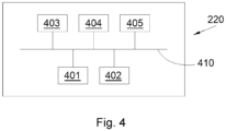
- FIG. 4 schematically illustrates an example of a control unit 220 implemented in the invention.
- the control unit 220 comprises, connected by a communication bus 410: a processor or CPU (Central Processing Unit) 401; a RAM (Read-Only Memory) 402; a read-only memory 403, for example of the ROM (Read Only Memory) or EEPROM (Electrically Erasable Programmable ROM) type, such as a Flash memory; a storage unit, such as a hard disk HDD (Hard Disk Drive) 404, or a storage media reader, such as an SD (Secure Digital) card reader; and an I/f interface manager 405.
- a processor or CPU Central Processing Unit
- RAM Read-Only Memory
- EEPROM Electrically Erasable Programmable ROM
- Flash memory Flash memory
- storage unit such as a hard disk HDD (Hard Disk Drive) 404, or a storage media reader, such as an SD (Secure Digital) card reader
- SD Secure Digital
- the I/f interface manager 405 allows the control unit 220 to interact with other components such as the detection means 218, the shut-off valves 216a-b, the discharge valve 222, etc.
- the processor 401 is capable of executing instructions loaded into the RAM 402 from the ROM 403, an external memory, a storage medium (such as an SD card), or a communications network. When the control unit 220 is powered on, the processor 401 is capable of reading instructions from the RAM 402 and executing them. These instructions form a computer program causing the processor 401 to implement all or part of the steps, methods, and operations described herein.
- control unit 220 comprises electronic circuitry adapted and configured to implement the operations, methods and steps described herein.
Landscapes
- Engineering & Computer Science (AREA)
- Chemical & Material Sciences (AREA)
- Combustion & Propulsion (AREA)
- Mechanical Engineering (AREA)
- General Engineering & Computer Science (AREA)
- Aviation & Aerospace Engineering (AREA)
- Pipeline Systems (AREA)
- Examining Or Testing Airtightness (AREA)
- Cooling, Air Intake And Gas Exhaust, And Fuel Tank Arrangements In Propulsion Units (AREA)
Description
- La présente invention concerne un module pour un système d'alimentation en dihydrogène pour un moteur d'aéronef, un système d'alimentation comprenant au moins deux tels modules, un aéronef comportant un tel module, ainsi qu'un aéronef comportant un tel système d'alimentation.
-
US2022146047A1 divulgue un tel module. - Afin de réduire les émissions de dioxyde de carbone (CO2) des moteurs d'aéronef, il est connu d'utiliser le dihydrogène comme carburant. L'aéronef comporte alors un réservoir de dihydrogène, et au moins un moteur alimenté par ledit dihydrogène grâce à des canalisations qui courent dans l'aéronef, entre le réservoir et chaque moteur et sur lesquelles des pompes, des réchauffeurs et des vannes sont installés.
- La sécurité doit être assurée si un incident intervient sur la ligne d'alimentation entre le réservoir et le moteur. Pour cela, il est connu de mettre en place différents systèmes de sécurité.
- Bien qu'un tel arrangement soit performant lorsqu'un seul incident intervient sur la ligne d'alimentation, il est nécessaire de prévoir un arrangement qui assure la sécurité lorsqu'un deuxième incident intervient sur la même ligne d'approvisionnement.
- Un objet de la présente invention est de proposer un module pour un système d'alimentation en dihydrogène pour un moteur d'un aéronef, où ledit module permet d'assurer une sécurité renforcée en cas d'incident.
- À cet effet, est proposé un module pour un système d'alimentation en dihydrogène pour un aéronef comportant un réservoir de dihydrogène et un moteur, ledit module comportant :
- un caisson extérieur présentant une entrée d'air et une sortie d'air,
- un caisson intérieur étanche, inerté et logé dans le caisson extérieur,
- une canalisation destinée à être fluidiquement connectée entre le réservoir et le moteur, et traversant le caisson extérieur et le caisson intérieur,
- un dispositif logé dans le caisson intérieur et arrangé pour agir sur le dihydrogène circulant dans la canalisation,
- un premier limiteur de pression monté sur la canalisation dans le caisson intérieur,
- un deuxième limiteur de pression monté sur le caisson intérieur,
- une canalisation d'échappement fluidiquement connectée entre le premier limiteur de pression, le deuxième limiteur de pression et l'extérieur de l'aéronef, en position montée du module dans l'aéronef,
- une vanne d'arrêt amont montée sur la canalisation au niveau de l'entrée de la canalisation dans le caisson extérieur,
- une vanne d'arrêt aval montée sur la canalisation au niveau de la sortie de la canalisation dans le caisson extérieur,
- des moyens de détection prévus pour détecter une fuite entre la canalisation et le caisson intérieur ou une fuite entre le caisson intérieur et le caisson extérieur et pour délivrer des informations représentatives d'une telle fuite, et
- une unité de contrôle arrangée pour commander en ouverture et en fermeture chaque vanne d'arrêt en fonction des informations délivrées par les moyens de détection.
- Avec un tel arrangement, si deux incidents successifs apparaissent sur le module, la sécurité est garantie par évacuation du dihydrogène vers l'extérieur. En outre, le dihydrogène provenant d'une fuite est dilué avec l'air ambiant, ce qui limite les risques d'inflammation.
- Avantageusement, la canalisation d'échappement débouche à l'extérieur de l'aéronef, en position montée du module dans l'aéronef, par l'intermédiaire d'un clapet anti-retour.
- Avantageusement, la partie de la canalisation entre le caisson intérieur et chaque vanne d'arrêt prend la forme d'une canalisation à double peau.
- Avantageusement, le module comporte un troisième limiteur de pression et un quatrième limiteur de pression, où le troisième limiteur de pression est monté entre la canalisation d'échappement et la canalisation en amont du caisson intérieur et où le quatrième limiteur de pression est monté entre la canalisation d'échappement et la canalisation en aval du caisson intérieur.
- Avantageusement, le caisson extérieur est destiné à être orienté de manière à présenter l'entrée d'air vers l'avant de l'aéronef et la sortie d'air vers l'arrière de l'aéronef, en position montée du module dans l'aéronef.
- Avantageusement, le module comporte une vanne de décharge montée sur la canalisation qui est dans le caisson intérieur et fluidiquement connectée à la canalisation d'échappement, où, sur commande de l'unité de contrôle, la vanne de décharge peut prendre alternativement une première position dans laquelle la vanne de décharge laisse le dihydrogène s'écouler dans la canalisation en empêchant l'écoulement du dihydrogène vers la canalisation d'échappement, et une deuxième position, dans laquelle la vanne de décharge laisse le dihydrogène s'écouler dans la canalisation et la canalisation d'échappement.
- L'invention propose également un système d'alimentation en dihydrogène pour un aéronef comportant un réservoir de dihydrogène et un moteur, ledit système d'alimentation comportant au moins deux modules selon l'une des variantes précédentes, où la canalisation est commune à tous les modules, où le caisson extérieur est commun à tous les modules, où les caissons intérieurs sont montés en série sur la canalisation.
- Avantageusement, les modules sont équipés des troisième et quatrième limiteurs de pression, et pour deux modules consécutifs le long de la canalisation, le quatrième limiteur de pression du deuxième module dans le sens d'écoulement du dihydrogène dans la canalisation est le troisième limiteur de pression du premier module.
- L'invention propose également un aéronef comportant un réservoir de dihydrogène, un moteur et un module selon l'une des variantes précédentes, où la canalisation est fluidiquement connectée entre le réservoir et le moteur.
- L'invention propose également un aéronef comportant un réservoir de dihydrogène, un moteur et un système d'alimentation selon l'une des variantes précédentes, où la canalisation est fluidiquement connectée entre le réservoir et le moteur.
- Les caractéristiques de l'invention mentionnées ci-dessus, ainsi que d'autres, apparaîtront plus clairement à la lecture de la description suivante d'un exemple de réalisation, ladite description étant faite en relation avec les dessins joints, parmi lesquels :
- La
figure 1 est une vue de côté d'un aéronef selon l'invention, - La
figure 2 est une représentation schématique d'un module selon l'invention, - La
figure 3 est une représentation schématique d'un système d'alimentation selon l'invention, et - La
figure 4 illustre schématiquement un exemple d'une unité de contrôle mise en œuvre dans l'invention. - Dans la description qui suit, les termes relatifs à une position sont pris en référence à un aéronef en position normale de vol, c'est-à-dire comme il est représenté sur la
figure 1 . - Dans la description qui suit, et par convention, on appelle X la direction longitudinale de l'aéronef, on appelle Y la direction transversale qui est horizontale lorsque l'aéronef est au sol, et Z la direction verticale qui est verticale lorsque l'aéronef est au sol, ces trois directions X, Y et Z étant orthogonales entre elles.
- La
figure 1 montre un aéronef 100 qui comporte un fuselage 102 de chaque côté duquel est fixée une aile 104 qui porte au moins un moteur 106 fonctionnant avec du dihydrogène comme carburant. Dans le mode de réalisation de l'invention présenté à lafigure 1 , le moteur 106 est un moteur à hélice, mais tout autre type de moteur est envisageable. - La flèche F indique la direction en marche avant de l'aéronef 100.
- L'aéronef 100 comporte au moins un réservoir 110 dans lequel est stocké le dihydrogène, préférentiellement sous forme liquide. Dans le mode de réalisation de l'invention, le réservoir 110 est disposé à l'arrière du fuselage 102, mais un positionnement différent est possible.
- L'aéronef 100 comporte également un système d'alimentation 150 qui assure la connexion fluidique entre un réservoir 110 et un moteur 106 logé dans une nacelle 108.
- Le système d'alimentation 150 comporte entre autres une canalisation générale 152 qui est fluidiquement connectée entre le réservoir 110 et le moteur 106 à alimenter.
- La
figure 2 montre un module 200 qui comporte une portion de la canalisation générale 152, à savoir une canalisation référencée 206 qui est donc destinée à être fluidiquement connectée entre le réservoir 110 et le moteur 106. De façon particulière, cette canalisation 206 est du type à double peau. - Le module 200 comporte un caisson extérieur 202 présentant une paroi formant une enveloppe et présentant une première ouverture formant une entrée d'air 202a et une deuxième ouverture formant une sortie d'air 202b. Le caisson extérieur 202 est par exemple la nacelle 108 ou tout autre élément délimitant un volume restreint. Un courant d'air avec de l'air provenant de l'extérieur de l'aéronef 100 peut alors se créer entre l'entrée d'air 202a et la sortie d'air 202b.
- Dans le mode de réalisation de l'invention présenté à la
figure 2 , le caisson extérieur 202 est orienté de manière à présenter l'entrée d'air 202a vers l'avant de l'aéronef 100 et la sortie d'air 202b vers l'arrière de l'aéronef 100 de manière à bénéficier de la pression dynamique créée pendant les phases de vol du fait du mouvement de l'aéronef 100 et ainsi assurer un bon écoulement de l'air dans le caisson extérieur 202. - Le module 200 comporte également un caisson intérieur 204 présentant une paroi qui est étanche et où le caisson intérieur 204 est logé dans le caisson extérieur 202. Le caisson intérieur 204 est inerté, soit par une mise au vide, soit par introduction d'un gaz inerte. De préférence, bien que non obligatoire, la pression du gaz inerte est supérieure à la pression du caisson extérieur 202, c'est-à-dire ici à la pression atmosphérique. Cela permet d'éviter que de l'air contenu dans le caisson extérieur 202 pénètre dans le caisson intérieur 204 en cas de fuite du caisson intérieur 204.
- La canalisation 206 traverse le caisson extérieur 202 et le caisson intérieur 204. La canalisation 206 traverse ainsi successivement la paroi du caisson extérieur 202, puis la paroi du caisson intérieur 204, puis à nouveau la paroi du caisson intérieur 204 et la paroi du caisson extérieur 202.
- Le module 200 comporte également un dispositif 208 logé dans le caisson intérieur 204. Le dispositif 208 est tout dispositif qui permet d'agir sur le dihydrogène circulant dans la canalisation 206 au niveau du caisson intérieur 204. Comme cela est expliqué ci-dessous, le dispositif peut être une pompe, un réchauffeur, ou autres.
- Le module 200 comporte un premier limiteur de pression 210a monté sur la canalisation 206 dans le caisson intérieur 204 et un deuxième limiteur de pression 210b monté sur le caisson intérieur 204.
- Associé aux premier et deuxième limiteurs de pression 210a-b, le module 200 comporte une canalisation d'échappement 212 fluidiquement connectée entre le premier limiteur de pression 210a, le deuxième limiteur de pression 210b et l'extérieur du caisson extérieur 202, et plus particulièrement l'extérieur de l'aéronef 100. Ainsi, si une surpression apparaît dans la canalisation 206 ou dans le caisson intérieur 204, les premier et deuxième limiteurs de pression 210a-b assurent l'échappement de la surpression vers l'extérieur du caisson extérieur 202, et plus particulièrement l'extérieur de l'aéronef 100. Les premiers et deuxièmes limiteurs de pression 210a-b peuvent présenter des pressions de décharge égales ou différentes.
- Dans le mode de réalisation de l'invention présenté à la
figure 2 , le premier limiteur de pression 210a est disposé en amont du dispositif 208 par rapport au sens de l'écoulement du dihydrogène dans la canalisation 206, mais il peut être disposé en aval dudit dispositif 208. - Le module 200 comporte également une vanne d'arrêt amont 216a montée sur la canalisation 206 au niveau de l'entrée de la canalisation 206 dans le caisson extérieur 202 et une vanne d'arrêt aval 216b montée sur la canalisation 206 au niveau de la sortie de la canalisation 206 dans le caisson extérieur 202.
- La vanne d'arrêt amont 216a est ainsi installée au niveau où la canalisation 206 traverse la paroi du caisson extérieur 202 pour rentrer dans ledit caisson extérieur 202 et la vanne d'arrêt aval 216b est ainsi installée au niveau où la canalisation 206 traverse la paroi du caisson extérieur 202 pour sortir dudit caisson extérieur 202. La vanne d'arrêt amont 216a et la vanne d'arrêt aval 216b sont préférentiellement des vannes pilotées électriquement, pneumatiquement, ou autre.
- Le module 200 comporte des moyens de détection 218 qui sont prévus pour détecter une fuite de dihydrogène entre la canalisation 206 et le caisson intérieur 204 ou une fuite entre le caisson intérieur 204 et le caisson extérieur 202.
- Le module 200 comporte une unité de contrôle 220 qui est en communication avec les moyens de détection 218 qui sont par ailleurs prévus pour délivrer des informations représentatives d'une fuite et ainsi en informer l'unité de contrôle 220.
- L'unité de contrôle 220 est, par ailleurs, arrangée pour commander en ouverture et en fermeture chaque vanne d'arrêt 216a-b en fonction des informations délivrées par les moyens de détection 218s et selon les besoins comme cela est expliqué ci-dessous.
- Avec un tel arrangement, même si deux incidents surviennent sur le module 200, la mise en sécurité dudit module 200 et l'évacuation du dihydrogène vers l'extérieur sont assurées comme cela est expliqué ci-dessous.
- Les moyens de détection 218 peuvent prendre différentes formes et peuvent être constitués d'un ou plusieurs capteurs de pression disposés dans le caisson intérieur 204. Ainsi, si un capteur de pression détecte une variation de pression dans le caisson intérieur 204 qui est sous vide ou sous une pression connue d'un gaz inerte, cela signifie qu'il y a une fuite. Les moyens de détection 218 peuvent être complétés par des capteurs de détection adaptés à la détection du dihydrogène et du dioxygène et l'analyse des données transmises par ces capteurs de détection permet de savoir si c'est la canalisation 206 qui fuit ou le caisson intérieur 204.
- Le fonctionnement va maintenant être décrit.
- Selon un premier mode de fonctionnement, si la canalisation 206 fuit à l'intérieur du caisson intérieur 204, le dihydrogène se répand dans le caisson intérieur 204 qui monte en pression jusqu'à ce que la pression de décharge (par exemple 3 bars) du deuxième limiteur de pression 210b soit atteinte et le deuxième limiteur de pression 210b s'ouvre sur la canalisation d'échappement 212 pour évacuer le dihydrogène vers l'extérieur. Du fait des variations de pression dans le caisson intérieur 204, les moyens de détection 218 détectent alors la présence de la fuite et informent l'unité de contrôle 220 qui commande la fermeture des deux vannes d'arrêt 216a-b. La fuite n'est plus alimentée et le caisson intérieur 204 reste rempli de dihydrogène à la pression de décharge du deuxième limiteur de pression 210b.
- Si, à la suite de la fuite précédente, une deuxième fuite intervient au niveau du caisson intérieur 204, c'est-à-dire que le dihydrogène se répand dans le caisson extérieur 202 qui est ventilé du fait du courant d'air entre l'entrée d'air 202a et la sortie d'air 202b. Le dihydrogène est ainsi évacué vers l'extérieur du caisson extérieur 202, et plus particulièrement l'extérieur de l'aéronef 100.
- Selon un deuxième mode de fonctionnement, lorsque le caisson intérieur 204 est inerté par une mise au vide ou lorsque la pression du gaz inerte dans le caisson intérieur 204 est inférieure à la pression du caisson extérieur 202, si une fuite intervient au niveau du caisson intérieur 204, l'air présent dans le caisson extérieur 202 se répand dans le caisson intérieur 204 qui monte en pression. Du fait des variations de pression dans le caisson intérieur 204, les moyens de détection 218 détectent alors la présence de la fuite et informent l'unité de contrôle 220 qui commande la fermeture des deux vannes d'arrêt 216a-b. La canalisation 206 est condamnée et elle reste remplie de dihydrogène à la pression de décharge du premier limiteur de pression 210a. Du fait du remplissage du caisson intérieur 204 par l'air, le caisson intérieur 204 perd ses caractéristiques d'isolant thermique pour la canalisation 206 présente dans ledit caisson intérieur 204. Le dihydrogène présent dans la canalisation 206 se réchauffe alors également, et la pression dans la canalisation 206 augmente jusqu'à ce que la pression de décharge (par exemple 60 bars) du premier limiteur de pression 210a soit atteinte et le premier limiteur de pression 210a s'ouvre sur la canalisation d'échappement 212 pour évacuer le dihydrogène vers l'extérieur du caisson extérieur 202, et plus particulièrement l'extérieur de l'aéronef 100.
- Si, à la suite de la fuite précédente, une deuxième fuite apparaît au niveau de la canalisation 206 qui fuit à l'intérieur du caisson intérieur 204, le dihydrogène de la canalisation 206 se répand dans le caisson intérieur 204 puis dans la canalisation d'échappement 212 à travers le premier limiteur de pression 210a ou dans le caisson extérieur 202 à travers la fuite au niveau du caisson intérieur 204. Le caisson extérieur 202 est ventilé du fait du courant d'air entre l'entrée d'air 202a et la sortie d'air 202b et le dihydrogène est ainsi évacué vers l'extérieur du caisson extérieur 202, et plus particulièrement vers l'extérieur de l'aéronef 100.
- Ainsi, avec un tel arrangement, même si deux incidents arrivent, la sécurité est assurée car les risques liés à la création d'un mélange explosif sont limités.
- Dans le mode de réalisation de l'invention présenté à la
figure 2 , la canalisation d'échappement 212 débouche à l'extérieur par l'intermédiaire d'un clapet anti-retour 214 pour éviter l'entrée de l'air extérieur dans le caisson intérieur 204. - Dans le mode de réalisation de l'invention présenté à la
figure 2 , la partie de la canalisation 206 qui est entre le caisson intérieur 204 et chaque vanne d'arrêt 216a-b, prend la forme d'une canalisation à double peau. - La partie de la canalisation 206 qui est dans le caisson intérieur 204 prend ici la forme d'une canalisation à simple peau.
- Dans le mode de réalisation de l'invention présenté à la
figure 2 , le module 200 comporte un troisième limiteur de pression 210c et un quatrième limiteur de pression 210d. - Le troisième limiteur de pression 210c est monté entre la canalisation d'échappement 212 et la canalisation 206 en amont du caisson intérieur 204 afin d'assurer un déchargement de la canalisation 206 vers la canalisation d'échappement 212 puis l'extérieur du caisson extérieur 202, et plus particulièrement l'extérieur de l'aéronef 100 si la pression dans la canalisation 206 dépasse la pression de décharge du troisième limiteur de pression 210c.
- De la même manière, le quatrième limiteur de pression 210d est monté entre la canalisation d'échappement 212 et la canalisation 206 en aval du caisson intérieur 204 afin d'assurer un déchargement de la canalisation 206 vers la canalisation d'échappement 212 puis l'extérieur du caisson extérieur 202, et plus particulièrement l'extérieur de l'aéronef 100 si la pression dans la canalisation 206 dépasse la pression de décharge du quatrième limiteur de pression 210d.
- Selon un mode de réalisation particulier de l'invention, le module 200 comporte une vanne de décharge 222 qui est commandée par l'unité de contrôle 220. La vanne de décharge 222 est montée sur la canalisation 206 qui est dans le caisson intérieur 204 et est fluidiquement connectée à la canalisation d'échappement 212. La vanne de décharge 222 est préférentiellement une vanne pilotée électriquement, pneumatiquement, ou autre.
- Sur commande de l'unité de contrôle 220, la vanne de décharge 222 peut prendre alternativement une première position dans laquelle la vanne de décharge 222 laisse le dihydrogène s'écouler dans la canalisation 206 en empêchant l'écoulement du dihydrogène vers la canalisation d'échappement 212, et une deuxième position, dans laquelle la vanne de décharge 222 laisse le dihydrogène s'écouler dans la canalisation 206 et la canalisation d'échappement 212 pour rejoindre l'extérieur du caisson extérieur 202, et plus particulièrement l'extérieur de l'aéronef 100.
- Ainsi, lorsqu'aucune fuite n'est détectée, l'unité de contrôle 220 commande la vanne de décharge 222 pour qu'elle prenne la première position, et lorsqu'une fuite est détectée et que les vannes d'arrêt 216a-b sont fermées, l'unité de contrôle commande le passage de la vanne de décharge 222 de la première position à la deuxième position pour que le dihydrogène présent dans la canalisation 206 s'évacue vers l'extérieur avant l'éventuelle apparition d'une deuxième fuite.
- Dans le mode de réalisation de l'invention présenté à la
figure 2 , la vanne de décharge 222 est en aval du dispositif 208, mais elle peut être en amont dudit dispositif 208. - La
figure 3 montre un exemple d'un système d'alimentation 150 selon l'invention dans lequel deux modules 200a-b selon l'invention ont été mis en place. D'une manière générale, un système d'alimentation 150 peut comporter au moins deux modules 200a-b. - La canalisation 206 est commune à tous les modules 200a-b.
- La canalisation d'échappement 212 est ici commune à tous les modules 200a-b et lorsqu'il est présent, le clapet anti-retour 214 est commun à tous les modules 200a-b, mais l'un comme l'autre peuvent être séparés.
- Le caisson extérieur 302 est commun à tous les modules 200a-b.
- L'unité de contrôle 220 est également ici commune à tous les modules 200a-b, mais chaque module 200a-b peut avoir sa propre unité de contrôle 220 qui communique avec les autres unités de contrôle 220.
- Ainsi dans un même caisson extérieur 302, les caissons intérieurs 304a-b sont montés en série sur la canalisation 206
- Lorsque les modules 200a-b sont équipés des troisième et quatrième limiteurs de pression 210c-d, pour deux modules 200a-b consécutifs le long de la canalisation 206, le quatrième limiteur de pression 210d du deuxième module 200b dans le sens d'écoulement du dihydrogène dans la canalisation 206 est le troisième limiteur de pression 210c du premier module 200a.
- Dans le mode de réalisation de l'invention présenté à la
figure 3 , la partie de la canalisation 206 qui est entre les caissons intérieurs 304a-b prend la forme d'une canalisation à double peau. - Selon un mode de réalisation particulier de l'invention, le dispositif 308a qui est dans le caisson 304a qui est juste en aval du réservoir 110 prend la forme d'une pompe, et le dispositif 308b qui est dans le caisson 304b qui est juste en amont du moteur 106 prend la forme d'un réchauffeur qui assure le passage du dihydrogène de la phase liquide à la phase gazeuse.
- Un tel réchauffeur 308b est par exemple un échangeur thermique qui assure un échange de calories entre un fluide caloporteur chaud et le dihydrogène froid, ou un système avec une résistance chauffante.
- Dans un mode de réalisation avantageux, le module 200 comporte en outre un ventilateur prévu pour améliorer la circulation de l'air entre l'entrée d'air 202a et la sortie d'air 202b. Ce ventilateur est contrôlé par l'unité de contrôle 220. Par exemple, l'unité de contrôle 220 commande le fonctionnement du ventilateur pendant des phases d'utilisation de l'aéronef au cours desquelles la circulation de l'air entre l'entrée d'air 202a et la sortie d'air 202b serait moindre en l'absence de fonctionnement du ventilateur, en particulier lorsque l'aéronef est stationné au sol.
- Dans un autre mode de réalisation avantageux, le caisson extérieur 202 comporte en outre une porte dite de surpression. Cette porte de surpression est fermée de façon étanche lors du fonctionnement normal de l'aéronef 100. Elle est prévue pour s'ouvrir vers l'extérieur du caisson extérieur 202 lorsque la pression à l'intérieur du caisson extérieur 202 est supérieure à une valeur de pression prédéterminée. Ainsi, dans l'hypothèse où la circulation de l'air entre l'entrée d'air 202a et la sortie d'air 202b ne permettrait pas une ventilation à l'intérieur du caisson extérieur 202 suffisante pour éviter d'avoir un mélange explosif à l'intérieur du caisson extérieur 202 suite à une fuite, la porte de surpression permet de protéger le caisson extérieur 202 en s'ouvrant si une explosion survient à l'intérieur du caisson extérieur 202. Dans un mode particulier de réalisation, le caisson intérieur 204 comporte également une porte de surpression. Ainsi, dans l'hypothèse où le débit à travers le premier limiteur de pression 210 ne permettrait pas une évacuation suffisante du gaz contenu dans le caisson intérieur 204 suite à une fuite, la porte de surpression du caisson intérieur 204 permet de protéger le caisson intérieur 204 en s'ouvrant si une explosion survient à l'intérieur du caisson intérieur 204.
- La
figure 4 illustre schématiquement un exemple d'une unité de contrôle 220 mise en œuvre dans l'invention. - L'unité de contrôle 220 comporte, reliés par un bus de communication 410 : un processeur ou CPU (« Central Processing Unit » en anglais) 401 ; une mémoire vive RAM (« Read-Only Memory » en anglais) 402 ; une mémoire morte 403, par exemple de type ROM (« Read Only Memory » en anglais) ou EEPROM (« Electrically-Erasable Programmable ROM » en anglais), telle qu'une mémoire Flash ; une unité de stockage, telle qu'un disque dur HDD (« Hard Disk Drive » en anglais) 404, ou un lecteur de support de stockage, tel qu'un lecteur de cartes SD (« Secure Digital » en anglais) ; et un gestionnaire d'interfaces I/f 405.
- Le gestionnaire d'interfaces I/f 405 permet à l'unité de contrôle 220 d'interagir avec les autres composants comme les moyens de détection 218, les vannes d'arrêt 216a-b, la vanne de décharge 222, etc.
- Le processeur 401 est capable d'exécuter des instructions chargées dans la mémoire vive 402 à partir de la mémoire morte 403, d'une mémoire externe, d'un support de stockage (tel qu'une carte SD), ou d'un réseau de communication. Lorsque l'unité de contrôle 220 est mise sous tension, le processeur 401 est capable de lire de la mémoire vive 402 des instructions et de les exécuter. Ces instructions forment un programme d'ordinateur causant l'implémentation, par le processeur 401, de tout ou partie des étapes, procédés et fonctionnements décrits ici.
- Tout ou partie des étapes, procédés et fonctionnements décrits ici peut ainsi être implémenté sous forme logicielle par exécution d'un ensemble d'instructions par une machine programmable, par exemple un processeur de type DSP (« Digital Signal Processor » en anglais) ou un microcontrôleur, ou être implémenté sous forme matérielle par une machine ou un composant électronique (« chip » en anglais) dédié ou un ensemble de composants électroniques (« chipset » en anglais) dédié, par exemple, un composant FPGA (« Field Programmable Gate Array » en anglais) ou ASIC (« Application Specific Integrated Circuit » en anglais). D'une manière générale, l'unité de contrôle 220 comporte de la circuiterie électronique adaptée et configurée pour implémenter les fonctionnements, procédés et étapes décrits ici.
Claims (10)
- Module (200) pour un système d'alimentation (150) en dihydrogène pour un aéronef (100) comportant un réservoir (110) de dihydrogène et un moteur (106), ledit module (200) comportant :- un caisson extérieur (202) présentant une entrée d'air (202a) et une sortie d'air (202b),- un caisson intérieur (204) étanche, inerté et logé dans le caisson extérieur (202),- une canalisation (206) destinée à être fluidiquement connectée entre le réservoir (110) et le moteur (106), et traversant le caisson extérieur (202) et le caisson intérieur (204),- un dispositif (208) logé dans le caisson intérieur (204) et arrangé pour agir sur le dihydrogène circulant dans la canalisation (206),- un premier limiteur de pression (210a) monté sur la canalisation (206) dans le caisson intérieur (204),- un deuxième limiteur de pression (210b) monté sur le caisson intérieur (204),- une canalisation d'échappement (212) fluidiquement connectée entre le premier limiteur de pression (210a), le deuxième limiteur de pression (210b) et l'extérieur de l'aéronef (100), en position montée du module (200) dans l'aéronef,- une vanne d'arrêt amont (216a) montée sur la canalisation (206) au niveau de l'entrée de la canalisation (206) dans le caisson extérieur (202),- une vanne d'arrêt aval (216b) montée sur la canalisation (206) au niveau de la sortie de la canalisation (206) dans le caisson extérieur (202),- des moyens de détection (218) prévus pour détecter une fuite entre la canalisation (206) et le caisson intérieur (204) ou une fuite entre le caisson intérieur (204) et le caisson extérieur (202) et pour délivrer des informations représentatives d'une telle fuite, et- une unité de contrôle (220) arrangée pour commander en ouverture et en fermeture chaque vanne d'arrêt (216a-b) en fonction des informations délivrées par les moyens de détection (218).
- Module (200) selon la revendication 1, caractérisé en ce que la canalisation d'échappement (212) débouche à l'extérieur de l'aéronef (100), en position montée du module (200) dans l'aéronef, par l'intermédiaire d'un clapet anti-retour (214).
- Module (200) selon l'une des revendications 1 ou 2, caractérisé en ce que la partie de la canalisation (206) entre le caisson intérieur (204) et chaque vanne d'arrêt (216a-b) prend la forme d'une canalisation à double peau.
- Module (200) selon l'une des revendications 1 à 3, caractérisé en ce qu'il comporte un troisième limiteur de pression (210c) et un quatrième limiteur de pression (210d), où le troisième limiteur de pression (210c) est monté entre la canalisation d'échappement (212) et la canalisation (206) en amont du caisson intérieur (204) et où le quatrième limiteur de pression (210d) est monté entre la canalisation d'échappement (212) et la canalisation (206) en aval du caisson intérieur (204).
- Module (200) selon l'une des revendications 1 à 4, caractérisé en ce que le caisson extérieur (202) est destiné à être orienté de manière à présenter l'entrée d'air (202a) vers l'avant de l'aéronef (100) et la sortie d'air (202b) vers l'arrière de l'aéronef (100), en position montée du module (200) dans l'aéronef.
- Module (200) selon l'une des revendications 1 à 5, caractérisé en ce qu'il comporte une vanne de décharge (222) montée sur la canalisation (206) qui est dans le caisson intérieur (204) et fluidiquement connectée à la canalisation d'échappement (212), où, sur commande de l'unité de contrôle (220), la vanne de décharge (222) peut prendre alternativement une première position dans laquelle la vanne de décharge (222) laisse le dihydrogène s'écouler dans la canalisation (206) en empêchant l'écoulement du dihydrogène vers la canalisation d'échappement (212), et une deuxième position, dans laquelle la vanne de décharge (222) laisse le dihydrogène s'écouler dans la canalisation (206) et la canalisation d'échappement (212).
- Système d'alimentation (150) en dihydrogène pour un aéronef (100) comportant un réservoir (110) de dihydrogène et un moteur (106), ledit système d'alimentation (150) comportant au moins deux modules (200a-b) selon l'une des revendications précédentes, où la canalisation (206) est commune à tous les modules (200a-b), où le caisson extérieur (302) est commun à tous les modules (200a-b), où les caissons intérieurs (304a-b) sont montés en série sur la canalisation (206).
- Système d'alimentation (150) selon la revendication 7, caractérisé en ce que les modules (200a-b) sont équipés des troisième et quatrième limiteurs de pression (210c-d), et en ce que pour deux modules (200a-b) consécutifs le long de la canalisation (206), le quatrième limiteur de pression (210d) du deuxième module (200b) dans le sens d'écoulement du dihydrogène dans la canalisation (206) est le troisième limiteur de pression (210c) du premier module (200a).
- Aéronef (100) comportant un réservoir (110) de dihydrogène, un moteur (106) et un module (200) selon l'une des revendications 1 à 6, où la canalisation (206) est fluidiquement connectée entre le réservoir (110) et le moteur (106).
- Aéronef (100) comportant un réservoir (110) de dihydrogène, un moteur (106) et un système d'alimentation (150) selon l'une des revendications 7 ou 8, où la canalisation (206) est fluidiquement connectée entre le réservoir (110) et le moteur (106).
Applications Claiming Priority (1)
| Application Number | Priority Date | Filing Date | Title |
|---|---|---|---|
| FR2302721A FR3146879A1 (fr) | 2023-03-23 | 2023-03-23 | Module pour un système d’alimentation en dihydrogène pour un moteur d’aéronef |
Publications (2)
| Publication Number | Publication Date |
|---|---|
| EP4435316A1 EP4435316A1 (fr) | 2024-09-25 |
| EP4435316B1 true EP4435316B1 (fr) | 2025-04-30 |
Family
ID=86851885
Family Applications (1)
| Application Number | Title | Priority Date | Filing Date |
|---|---|---|---|
| EP24161321.5A Active EP4435316B1 (fr) | 2023-03-23 | 2024-03-05 | Module pour un système d'alimentation en dihydrogène pour un moteur d'aéronef |
Country Status (4)
| Country | Link |
|---|---|
| US (1) | US12420944B2 (fr) |
| EP (1) | EP4435316B1 (fr) |
| CN (1) | CN118686697A (fr) |
| FR (1) | FR3146879A1 (fr) |
Family Cites Families (5)
| Publication number | Priority date | Publication date | Assignee | Title |
|---|---|---|---|---|
| WO2012045031A1 (fr) * | 2010-09-30 | 2012-04-05 | General Electric Company | Système de réservoir à combustible d'avion |
| GB2587558B (en) * | 2018-10-15 | 2021-12-01 | Gkn Aerospace Services Ltd | Apparatus |
| FR3094070B1 (fr) * | 2019-03-21 | 2021-10-15 | Air Liquide | Dispositif et procédé de stockage et de fourniture de carburant fluide. |
| US12258142B2 (en) * | 2021-04-27 | 2025-03-25 | Eaton Intelligent Power Limited | System and method for reducing the concentration of fuel vapor in the ullage of a fuel tank |
| US12253033B2 (en) * | 2022-10-04 | 2025-03-18 | General Electric Company | Hydrogen fuel leak detection system for a vehicle |
-
2023
- 2023-03-23 FR FR2302721A patent/FR3146879A1/fr not_active Ceased
-
2024
- 2024-03-05 EP EP24161321.5A patent/EP4435316B1/fr active Active
- 2024-03-15 CN CN202410299060.1A patent/CN118686697A/zh active Pending
- 2024-03-18 US US18/608,140 patent/US12420944B2/en active Active
Also Published As
| Publication number | Publication date |
|---|---|
| US12420944B2 (en) | 2025-09-23 |
| EP4435316A1 (fr) | 2024-09-25 |
| US20240317419A1 (en) | 2024-09-26 |
| FR3146879A1 (fr) | 2024-09-27 |
| CN118686697A (zh) | 2024-09-24 |
Similar Documents
| Publication | Publication Date | Title |
|---|---|---|
| EP4166771B1 (fr) | Ensemble propulsif pour aéronef | |
| EP4124738B1 (fr) | Ensemble propulsif pour aéronef | |
| EP4371885B1 (fr) | Aéronef comportant un système d'alimentation en dihydrogène | |
| EP3237737B1 (fr) | Procédé de détection de fuite de fluide dans une turbomachine et système de distribution de fluide | |
| CA2929951A1 (fr) | Ensemble propulsif d'aeronef avec systeme d'extinction de feu | |
| EP4030043B1 (fr) | Ensemble propulsif pour aéronef comportant un système de ventilation et un système anti-incendie | |
| FR3094892A1 (fr) | Systeme anti-incendie pour un aeronef comportant un reservoir a double chambre | |
| EP4435316B1 (fr) | Module pour un système d'alimentation en dihydrogène pour un moteur d'aéronef | |
| EP4311778B1 (fr) | Système d'alimentation en dihydrogène pour un moteur d'aéronef | |
| EP3887652A1 (fr) | Circuit de drainage d'une chambre de combustion et procede de determination de defaillance d'un tel circuit | |
| EP4438488B1 (fr) | Ensemble propulsif d'aéronef comportant une nacelle avec un châssis en t | |
| EP4293212B1 (fr) | Système de boîtier contenant un échangeur thermique pour réchauffer du dihydrogène | |
| FR3158953A1 (fr) | Ensemble propulsif pour aéronef comportant un ventilateur d’extraction | |
| EP4286019B1 (fr) | Aéronef comportant une canalisation de transport de dihydrogène, un canal d'enfouissement de ladite canalisation de transport et un système d'aération dudit canal d'enfouissement | |
| EP4495008B1 (fr) | Nacelle d aéronef comportant un caisson étanche et une porte ouvrant le caisson sur l extérieur | |
| EP4345009B1 (fr) | Ensemble propulsif pour aéronef | |
| FR3153077A1 (fr) | Ensemble propulsif pour aéronef | |
| EP4311779B1 (fr) | Système d'alimentation en dihydrogène pour un moteur d'aéronef | |
| EP4538513A1 (fr) | Ensemble propulsif pour aéronef | |
| EP4438487B1 (fr) | Aéronef comportant une canalisation de transport de dihydrogène, un canal d'enfouissement de ladite canalisation de transport et un système d'évacuation de l'air et de l'eau présente dans ledit canal d'enfouissement | |
| EP4538515A1 (fr) | Ensemble propulsif pour aéronef comportant un système d'échange thermique dans la tuyère d'éjection | |
| EP4538514A1 (fr) | Ensemble propulsif pour aéronef | |
| EP4696407A1 (fr) | Installation pour aéronef comportant un réservoir délimitant un volume avec un point haut et un élément contenant du dihydrogène | |
| EP4452757A1 (fr) | Intégration d'un extincteur en zone "feu" d'une turbomachine |
Legal Events
| Date | Code | Title | Description |
|---|---|---|---|
| PUAI | Public reference made under article 153(3) epc to a published international application that has entered the european phase |
Free format text: ORIGINAL CODE: 0009012 |
|
| STAA | Information on the status of an ep patent application or granted ep patent |
Free format text: STATUS: REQUEST FOR EXAMINATION WAS MADE |
|
| 17P | Request for examination filed |
Effective date: 20240305 |
|
| AK | Designated contracting states |
Kind code of ref document: A1 Designated state(s): AL AT BE BG CH CY CZ DE DK EE ES FI FR GB GR HR HU IE IS IT LI LT LU LV MC ME MK MT NL NO PL PT RO RS SE SI SK SM TR |
|
| GRAP | Despatch of communication of intention to grant a patent |
Free format text: ORIGINAL CODE: EPIDOSNIGR1 |
|
| STAA | Information on the status of an ep patent application or granted ep patent |
Free format text: STATUS: GRANT OF PATENT IS INTENDED |
|
| RIC1 | Information provided on ipc code assigned before grant |
Ipc: F17C 13/12 20060101AFI20241014BHEP |
|
| INTG | Intention to grant announced |
Effective date: 20241025 |
|
| RAP3 | Party data changed (applicant data changed or rights of an application transferred) |
Owner name: AIRBUS (S.A.S.) Owner name: AIRBUS OPERATIONS (S.A.S.) |
|
| GRAS | Grant fee paid |
Free format text: ORIGINAL CODE: EPIDOSNIGR3 |
|
| GRAA | (expected) grant |
Free format text: ORIGINAL CODE: 0009210 |
|
| STAA | Information on the status of an ep patent application or granted ep patent |
Free format text: STATUS: THE PATENT HAS BEEN GRANTED |
|
| AK | Designated contracting states |
Kind code of ref document: B1 Designated state(s): AL AT BE BG CH CY CZ DE DK EE ES FI FR GB GR HR HU IE IS IT LI LT LU LV MC ME MK MT NL NO PL PT RO RS SE SI SK SM TR |
|
| REG | Reference to a national code |
Ref country code: CH Ref legal event code: EP Ref country code: GB Ref legal event code: FG4D Free format text: NOT ENGLISH |
|
| REG | Reference to a national code |
Ref country code: IE Ref legal event code: FG4D Free format text: LANGUAGE OF EP DOCUMENT: FRENCH |
|
| REG | Reference to a national code |
Ref country code: DE Ref legal event code: R096 Ref document number: 602024000088 Country of ref document: DE |
|
| REG | Reference to a national code |
Ref country code: NL Ref legal event code: MP Effective date: 20250430 |
|
| REG | Reference to a national code |
Ref country code: AT Ref legal event code: MK05 Ref document number: 1790299 Country of ref document: AT Kind code of ref document: T Effective date: 20250430 |
|
| PG25 | Lapsed in a contracting state [announced via postgrant information from national office to epo] |
Ref country code: PT Free format text: LAPSE BECAUSE OF FAILURE TO SUBMIT A TRANSLATION OF THE DESCRIPTION OR TO PAY THE FEE WITHIN THE PRESCRIBED TIME-LIMIT Effective date: 20250901 Ref country code: FI Free format text: LAPSE BECAUSE OF FAILURE TO SUBMIT A TRANSLATION OF THE DESCRIPTION OR TO PAY THE FEE WITHIN THE PRESCRIBED TIME-LIMIT Effective date: 20250430 Ref country code: ES Free format text: LAPSE BECAUSE OF FAILURE TO SUBMIT A TRANSLATION OF THE DESCRIPTION OR TO PAY THE FEE WITHIN THE PRESCRIBED TIME-LIMIT Effective date: 20250430 |
|
| REG | Reference to a national code |
Ref country code: LT Ref legal event code: MG9D |
|
| PG25 | Lapsed in a contracting state [announced via postgrant information from national office to epo] |
Ref country code: NO Free format text: LAPSE BECAUSE OF FAILURE TO SUBMIT A TRANSLATION OF THE DESCRIPTION OR TO PAY THE FEE WITHIN THE PRESCRIBED TIME-LIMIT Effective date: 20250730 Ref country code: GR Free format text: LAPSE BECAUSE OF FAILURE TO SUBMIT A TRANSLATION OF THE DESCRIPTION OR TO PAY THE FEE WITHIN THE PRESCRIBED TIME-LIMIT Effective date: 20250731 |
|
| PG25 | Lapsed in a contracting state [announced via postgrant information from national office to epo] |
Ref country code: PL Free format text: LAPSE BECAUSE OF FAILURE TO SUBMIT A TRANSLATION OF THE DESCRIPTION OR TO PAY THE FEE WITHIN THE PRESCRIBED TIME-LIMIT Effective date: 20250430 Ref country code: NL Free format text: LAPSE BECAUSE OF FAILURE TO SUBMIT A TRANSLATION OF THE DESCRIPTION OR TO PAY THE FEE WITHIN THE PRESCRIBED TIME-LIMIT Effective date: 20250430 |
|
| PG25 | Lapsed in a contracting state [announced via postgrant information from national office to epo] |
Ref country code: BG Free format text: LAPSE BECAUSE OF FAILURE TO SUBMIT A TRANSLATION OF THE DESCRIPTION OR TO PAY THE FEE WITHIN THE PRESCRIBED TIME-LIMIT Effective date: 20250430 |
|
| PG25 | Lapsed in a contracting state [announced via postgrant information from national office to epo] |
Ref country code: HR Free format text: LAPSE BECAUSE OF FAILURE TO SUBMIT A TRANSLATION OF THE DESCRIPTION OR TO PAY THE FEE WITHIN THE PRESCRIBED TIME-LIMIT Effective date: 20250430 |
|
| PG25 | Lapsed in a contracting state [announced via postgrant information from national office to epo] |
Ref country code: AT Free format text: LAPSE BECAUSE OF FAILURE TO SUBMIT A TRANSLATION OF THE DESCRIPTION OR TO PAY THE FEE WITHIN THE PRESCRIBED TIME-LIMIT Effective date: 20250430 |
|
| PG25 | Lapsed in a contracting state [announced via postgrant information from national office to epo] |
Ref country code: RS Free format text: LAPSE BECAUSE OF FAILURE TO SUBMIT A TRANSLATION OF THE DESCRIPTION OR TO PAY THE FEE WITHIN THE PRESCRIBED TIME-LIMIT Effective date: 20250731 |
|
| PG25 | Lapsed in a contracting state [announced via postgrant information from national office to epo] |
Ref country code: IS Free format text: LAPSE BECAUSE OF FAILURE TO SUBMIT A TRANSLATION OF THE DESCRIPTION OR TO PAY THE FEE WITHIN THE PRESCRIBED TIME-LIMIT Effective date: 20250830 |
|
| PG25 | Lapsed in a contracting state [announced via postgrant information from national office to epo] |
Ref country code: LV Free format text: LAPSE BECAUSE OF FAILURE TO SUBMIT A TRANSLATION OF THE DESCRIPTION OR TO PAY THE FEE WITHIN THE PRESCRIBED TIME-LIMIT Effective date: 20250430 |
|
| PG25 | Lapsed in a contracting state [announced via postgrant information from national office to epo] |
Ref country code: SM Free format text: LAPSE BECAUSE OF FAILURE TO SUBMIT A TRANSLATION OF THE DESCRIPTION OR TO PAY THE FEE WITHIN THE PRESCRIBED TIME-LIMIT Effective date: 20250430 Ref country code: DK Free format text: LAPSE BECAUSE OF FAILURE TO SUBMIT A TRANSLATION OF THE DESCRIPTION OR TO PAY THE FEE WITHIN THE PRESCRIBED TIME-LIMIT Effective date: 20250430 |
|
| PG25 | Lapsed in a contracting state [announced via postgrant information from national office to epo] |
Ref country code: CZ Free format text: LAPSE BECAUSE OF FAILURE TO SUBMIT A TRANSLATION OF THE DESCRIPTION OR TO PAY THE FEE WITHIN THE PRESCRIBED TIME-LIMIT Effective date: 20250430 |
|
| PG25 | Lapsed in a contracting state [announced via postgrant information from national office to epo] |
Ref country code: EE Free format text: LAPSE BECAUSE OF FAILURE TO SUBMIT A TRANSLATION OF THE DESCRIPTION OR TO PAY THE FEE WITHIN THE PRESCRIBED TIME-LIMIT Effective date: 20250430 |
|
| PG25 | Lapsed in a contracting state [announced via postgrant information from national office to epo] |
Ref country code: SK Free format text: LAPSE BECAUSE OF FAILURE TO SUBMIT A TRANSLATION OF THE DESCRIPTION OR TO PAY THE FEE WITHIN THE PRESCRIBED TIME-LIMIT Effective date: 20250430 |
|
| PG25 | Lapsed in a contracting state [announced via postgrant information from national office to epo] |
Ref country code: IT Free format text: LAPSE BECAUSE OF FAILURE TO SUBMIT A TRANSLATION OF THE DESCRIPTION OR TO PAY THE FEE WITHIN THE PRESCRIBED TIME-LIMIT Effective date: 20250430 |
|
| REG | Reference to a national code |
Ref country code: DE Ref legal event code: R097 Ref document number: 602024000088 Country of ref document: DE |
|
| PLBE | No opposition filed within time limit |
Free format text: ORIGINAL CODE: 0009261 |
|
| STAA | Information on the status of an ep patent application or granted ep patent |
Free format text: STATUS: NO OPPOSITION FILED WITHIN TIME LIMIT |
|
| REG | Reference to a national code |
Ref country code: CH Ref legal event code: L10 Free format text: ST27 STATUS EVENT CODE: U-0-0-L10-L00 (AS PROVIDED BY THE NATIONAL OFFICE) Effective date: 20260311 |
|
| 26N | No opposition filed |
Effective date: 20260202 |
|
| PGFP | Annual fee paid to national office [announced via postgrant information from national office to epo] |
Ref country code: DE Payment date: 20260319 Year of fee payment: 3 |
|
| PGFP | Annual fee paid to national office [announced via postgrant information from national office to epo] |
Ref country code: FR Payment date: 20260323 Year of fee payment: 3 |