EP4435305A1 - Pipeline connecting structure and stop valve - Google Patents
Pipeline connecting structure and stop valve Download PDFInfo
- Publication number
- EP4435305A1 EP4435305A1 EP22894981.4A EP22894981A EP4435305A1 EP 4435305 A1 EP4435305 A1 EP 4435305A1 EP 22894981 A EP22894981 A EP 22894981A EP 4435305 A1 EP4435305 A1 EP 4435305A1
- Authority
- EP
- European Patent Office
- Prior art keywords
- connecting pipe
- section
- solder
- pipe body
- pipeline
- Prior art date
- Legal status (The legal status is an assumption and is not a legal conclusion. Google has not performed a legal analysis and makes no representation as to the accuracy of the status listed.)
- Pending
Links
Images

Classifications
-
- F—MECHANICAL ENGINEERING; LIGHTING; HEATING; WEAPONS; BLASTING
- F16—ENGINEERING ELEMENTS AND UNITS; GENERAL MEASURES FOR PRODUCING AND MAINTAINING EFFECTIVE FUNCTIONING OF MACHINES OR INSTALLATIONS; THERMAL INSULATION IN GENERAL
- F16L—PIPES; JOINTS OR FITTINGS FOR PIPES; SUPPORTS FOR PIPES, CABLES OR PROTECTIVE TUBING; MEANS FOR THERMAL INSULATION IN GENERAL
- F16L13/00—Non-disconnectable pipe joints, e.g. soldered, adhesive, or caulked joints
- F16L13/02—Welded joints
- F16L13/0218—Welded joints having an inner or outer ring
- F16L13/0227—Welded joints having an inner or outer ring having an inner ring
-
- F—MECHANICAL ENGINEERING; LIGHTING; HEATING; WEAPONS; BLASTING
- F16—ENGINEERING ELEMENTS AND UNITS; GENERAL MEASURES FOR PRODUCING AND MAINTAINING EFFECTIVE FUNCTIONING OF MACHINES OR INSTALLATIONS; THERMAL INSULATION IN GENERAL
- F16L—PIPES; JOINTS OR FITTINGS FOR PIPES; SUPPORTS FOR PIPES, CABLES OR PROTECTIVE TUBING; MEANS FOR THERMAL INSULATION IN GENERAL
- F16L13/00—Non-disconnectable pipe joints, e.g. soldered, adhesive, or caulked joints
- F16L13/08—Soldered joints
-
- F—MECHANICAL ENGINEERING; LIGHTING; HEATING; WEAPONS; BLASTING
- F16—ENGINEERING ELEMENTS AND UNITS; GENERAL MEASURES FOR PRODUCING AND MAINTAINING EFFECTIVE FUNCTIONING OF MACHINES OR INSTALLATIONS; THERMAL INSULATION IN GENERAL
- F16K—VALVES; TAPS; COCKS; ACTUATING-FLOATS; DEVICES FOR VENTING OR AERATING
- F16K1/00—Lift valves or globe valves, i.e. cut-off apparatus with closure members having at least a component of their opening and closing motion perpendicular to the closing faces
- F16K1/02—Lift valves or globe valves, i.e. cut-off apparatus with closure members having at least a component of their opening and closing motion perpendicular to the closing faces with screw-spindle
-
- F—MECHANICAL ENGINEERING; LIGHTING; HEATING; WEAPONS; BLASTING
- F25—REFRIGERATION OR COOLING; COMBINED HEATING AND REFRIGERATION SYSTEMS; HEAT PUMP SYSTEMS; MANUFACTURE OR STORAGE OF ICE; LIQUEFACTION SOLIDIFICATION OF GASES
- F25B—REFRIGERATION MACHINES, PLANTS OR SYSTEMS; COMBINED HEATING AND REFRIGERATION SYSTEMS; HEAT PUMP SYSTEMS
- F25B1/00—Compression machines, plants or systems with non-reversible cycle
Definitions
- the present invention relates to the field of pipeline welding technology, and in particular, to a pipeline connecting structure and a stop valve.
- a connecting pipe is a common media circulation carrier.
- the connecting pipe is used in a system pipeline, and the connecting pipe is usually connected and in communication with an external pipeline or an equipment cavity by welding.
- the connecting pipe in the related art is applied to a system pipeline of equipment.
- a solder used for welding melts and the two pipelines are welded and fixed
- excessive solder will permeate along an inner wall of the connecting pipe and form an internal flow welding, which will enter the equipment cavity through the connecting pipe in more serious cases, which will not only affect assembly of other parts in the equipment, but also cause welding chips to fall off in subsequent use.
- a pipeline connecting structure and a stop valve are provided.
- the present invention provides a pipeline connecting structure.
- the pipeline connecting structure includes a connecting pipe body, the connecting pipe body is provided with a solder blocking portion.
- the solder blocking portion is capable of blocking a solder from flowing on an inner wall of the connecting pipe body, to limit the solder from flowing out from an end of the connecting pipe body along a flow direction of the solder.
- the number of the solder blocking portions is multiple, and a plurality of solder blocking portions are arranged at intervals.
- the solder blocking portion includes a first solder blocking portion and a second solder blocking portion.
- the first solder blocking portion is disposed on an inner wall of the connecting pipe body.
- the second solder blocking portion is disposed on an end of the connecting pipe body.
- a distance between the first solder blocking port and the second solder blocking port is defined as a , and the distance a between the first solder blocking portion and the second solder blocking portion satisfies following formula: 0.5 mm ⁇ a ⁇ 5 mm.
- the solder blocking portion is defined by a part of the inner wall of the connecting pipe body protruding in a direction of a center line of the connecting pipe body.
- a first blocking section is defined by a part of the connecting pipe body being bent inward along the flow direction of the solder, and the solder blocking portion is a part of the inner wall of the connecting pipe body where the first blocking section is located.
- a groove is defined on an outer edge of an end of the connecting pipe body in a direction opposite to the flow direction of the solder, and when the connecting pipe body is inserted into an external pipeline, the groove of the connecting pipe body is capable of fitting with the external pipeline to form the solder blocking portion.
- the groove is in an annular shape, and a diameter of the groove gradually decreases along the flow direction of the solder.
- the pipeline connecting structure further includes a transition connecting pipe.
- the transition connecting pipe is sleeved on the connecting pipe body and welded and fixed with the connecting pipe body.
- the pipeline connecting structure further includes a transition connecting pipe.
- One end of the transition connecting pipe is connected with the connecting pipe body and the other end of the transition connecting pipe is connected with an external pipeline.
- the connecting pipe body is sleeved on the transition connecting pipe, and the connecting pipe body is provided with the solder blocking portion.
- the transition connecting pipe is provided with a switching blocking portion, the solder blocking portion and the switching blocking portion are capable of blocking the solder from flowing on the inner wall of the connecting pipe body, so as to limit the solder from flowing out from an end of the connecting pipe body away the transition connecting pipe.
- the solder blocking portion is formed by a part of the connecting pipe body protruding towards an axis of the connecting pipe body.
- the connecting pipe body includes a first connecting section, a second connecting section, and a first blocking section.
- the first connecting section is located at an end of the connecting pipe body proximal to the transition connecting pipe.
- the second connecting section is located at an end of the connecting pipe body away from the transition connecting pipe.
- the first blocking section is located between the first connecting section and the second connecting section, and two ends of the first blocking section are respectively connected with the first connecting section and the second connecting section.
- a diameter of the first connecting section is greater than a diameter of the second connecting section, and along an axis of the connecting pipe body, a diameter of the first blocking section gradually decreases from the first connecting section to the second connecting section.
- the transition connecting pipe includes a guide inclined plane, and the guide inclined plane is arranged at an end of the transition connecting pipe away from the connecting pipe body.
- the switching blocking portion is formed by a part of the transition connecting pipe protruding towards an axis of the transition connecting pipe.
- the transition connecting pipe includes a first switching section, a second switching section, and a second blocking section.
- the first switching section is located at an end of the transition connecting pipe away from the connecting pipe body.
- the second switching section is located at an end of the transition connecting pipe proximal to the connecting pipe body.
- the second blocking section is located between the first switching section and the second switching section, and two ends of the second blocking section are respectively connected with the first switching section and the second switching section.
- a diameter of the first switching section is greater than a diameter of the second switching section, and along an axial direction of the transition connecting pipe, a diameter of the second blocking section gradually decreases from the first switching section to the second switching section.
- At least a part of the second switching section extends into the first connecting section and abuts against the first blocking section, and the second switching section and the first connecting section are connected with each other.
- the diameter of the first connecting section is equal to the diameter of the first switching section.
- the connecting pipe body is made of stainless-steel and the transition connecting pipe is made of copper.
- the present invention further provides a stop valve, a stop valve includes a valve body and a pipeline connecting structure, the pipeline connecting structure is disposed on the valve body, and the valve body is capable of installing on a system pipeline through the pipeline connecting structure.
- the pipeline connecting structure is the above pipeline connecting structure.
- 1000 represents a stop valve
- 100 represents a pipeline connecting structure
- 10 represents a connecting pipe body
- 101 represents an inner wall
- 111 represents a solder blocking portion
- 111a represents a first solder blocking portion
- 111b represents a second solder blocking portion
- 112 represents a first connecting section
- 113 represents a second connecting section
- 114 represents a first blocking section
- 12 represents a groove
- 20 represents a transition connecting pipe
- 121 represents a switching blocking portion
- 122 represents a first switching section
- 123 represents a second switching section
- 124 represents a second blocking section
- 125 represents a guide inclined plane
- 30 represents an external pipeline
- 200 represents a valve body
- 201 represents a first opening
- 202 represents a second opening
- 300 represents a valve seat
- 400 represents a valve core.
- the component when the component is referred to as being “mounted to” another component, it may be directly on the other component or may also be an intervening component. When one component is considered to be “disposed on” another component, it may be directly disposed on another component or there may be an intervening component simultaneously. When one component is considered to be “fixed to” another component, it may be directly fixed on another component or there may be an intervening component at the same time.
- a pipeline connecting structure 100 in present application can play a role in blocking a flow of a solder.
- the pipeline connecting structure 100 of the present application is specifically applied in a stop valve 1000, so that the stop valve 1000 is welded and fixed with an external pipeline 30 (such as an air conditioning pipeline) through the pipeline connecting structure 100. It can prevent the excessive solder from flowing through the pipeline connecting structure 100 and entering the stop valve 1000 during welding, thereby preventing internal welding flow.
- the pipeline connecting structure 100 in present application is not limited to the stop valve 1000.
- the pipeline connecting structure 100 can be applied to solenoid valves or other system pipelines, as long as it can play the same role, which will not be described here.
- the present invention provides a pipeline connecting structure 100.
- the pipeline connecting structure 100 includes a connecting pipe body 10and a solder blocking portion 111 disposed on the connecting pipe body 10.
- the solder blocking portion 111 in the present invention can block a solder (not shown) from flowing on an inner wall 101 of the connecting pipe body 10, so as to restrict the solder from flowing out from an end of the connecting pipe body 10along a flow direction of the solder. That is, the connecting pipe body 10 of this embodiment can play a role of preventing an internal flow welding. Therefore, when the connecting pipe body 10 is applied to the stop valve 1000, the solder can be prevented from infiltrating into the valve body 200. Furthermore, a normal assembly between other parts of the stop valve 1000 and the valve body 200 is ensured. And at the same time, a blocking phenomenon of the stop valve 1000 caused by falling off of welding chips is avoided. It should be noted that the above-mentioned internal flow welding specifically means that the solder flows on the inner wall 101 of the connecting pipe body 10 and flows out from an end of the connecting pipe body 10.
- the solder can be multiple restricted by the connecting pipe body 10, which improves a barrier effect on the solder and further prevent an internal flow welding in the connecting pipe body 10.
- a plurality of the solder blocking portions 111 are arranged at intervals, so that a preset gap is defined between adjacent two of the solder blocking portions 111. In this way, the solder can be cooled as much as possible during a period from flowing through the previous solder blocking portion 111 to a next solder blocking portion 111, thus further improving a blocking effect of the solder by the connecting pipe body 10.
- the solder blocking portion 111 includes a first solder blocking portion 111a and a second solder blocking portion 111b.
- the first solder blocking portion 111a is disposed on the inner wall of the connecting pipe body 10, and the second solder blocking portion 11 1b is disposed on an end of the connecting pipe body 10.
- the solder blocking portion 111 is formed by a part of the inner wall 101 of the connecting pipe body 10 protruding in a direction of a center line of the connecting pipe body 10. In this way, through arrangement of the solder blocking portion 111 on the connecting pipe body 10, the connecting pipe body 10 can use such protruding structure on the inner wall 101 of the connecting pipe body 10 to block the flow of the solder.
- a part of the connecting pipe body 10 is bent inward to form a first blocking section 114, and a part of the inner wall 101 where the first blocking section 114 is located is regarded as the solder blocking portion 111.
- the connecting pipe body 10 of this embodiment can use the inner wall 101 where the first blocking section 114 is located as the solder blocking portion 111 to restrict the flow of the solder, so as to process and form the solder blocking portion 111 on the connecting pipe body 10, which has a simplified structure and facilitates a production and preparation of the connecting pipe body 10.
- the solder blocking portion 111 arranged on the inner wall 101 of the connecting pipe body 10 is not limited to illustration.
- a protruding structure can also be directly arranged on the inner wall 101 of the connecting pipe body 10, which will not be described here.
- a groove 12 is disposed on an outer edge of an end of the connecting pipe body 10 in a direction opposite to the flow direction of the solder, and when the connecting pipe body 10 is inserted into an external pipeline 30, the groove 12 of the connecting pipe body 10 is capable of fitting with the external pipeline 30 to form the solder blocking portion 111.
- the groove 12 provided at the end of the connecting pipe body 10 can be used and regarded as the solder blocking portion 111 for restricting the flow of the solder. So that the connecting pipe body 10 can use the groove 12 to accommodate the solder flowing into the connecting pipe body 10 during operation, thereby achieving the purpose of blocking the solder from flowing.
- the structural arrangement of the solder blocking portion 111 on the connecting pipe body 10 can be realized in the above manners, so that the connecting pipe body 10 can choose to provide with the groove 12 at the end of the connecting pipe body 10 as required, then the groove 12 cooperates with the external pipeline 30 to achieve the purpose of blocking the solder. Furthermore, a structural diversity of setting the solder blocking portion on the connecting pipe body 10 is increased.
- the groove 12 is in an annular shape, so as to meet the use requirements of welding and fixing with a welding ring during pipeline welding, and ensure that the groove 12 disposed at the end of the connecting pipe body 10 can play a role in blocking the solder.
- the diameter of the groove 12 gradually decreases, so as to facilitate the solder to enter the groove 12 of the connecting pipe body 10 and cooperate with the external pipeline 30 to realize a barrier to the solder, which has an effect of further improving the barrier of the groove 12 provided on the connecting pipe body 10 to the solder.
- the number of the first blocking section 114 for blocking the solder in the pipeline connecting structure 100 of the present invention is at least one, and the number of the groove 12 for blocking the solder is one, which will not be described here.
- the groove 12 for blocking the solder or the first blocking section 114 for blocking the solder may be separately provided on the pipeline connecting structure 100.
- the external pipeline 30 can be set as a transition connecting pipe 20, which is sleeved on the connecting pipe body 10 and welded and fixed with the connecting pipe body 10.
- the connecting pipe body 10 and the transition connecting pipe 20 cooperate with each other to form the solder blocking portion 111, which is used to block the solder when the transition connecting pipe 20 is welded with other pipelines.
- the stop valve is used to cut off and throttle the medium in the pipeline where it is located.
- the pipeline connecting structure 100 further includes a transition connecting pipe 20.
- One end of the transition connecting pipe 20 is connected with the connecting pipe body 10 and the other end of the transition connecting pipe 20 is connected with the external pipeline 30.
- the connecting pipe body 10 is sleeved on the transition connecting pipe 20, and the connecting pipe body 10 is provided with a solder blocking portion 111.
- the transition connecting pipe 20 is provided with a switching blocking portion 121, the solder blocking portion 111 and the switching blocking portion 121 can prevent the solder from flowing on an inner wall of the connecting pipe body 10, so as to limit the solder from flowing out from the end of the connecting pipe body 10 away from the transition connecting pipe 20. It can be understood that by providing the solder blocking portion and the switching blocking portion, the flow of the solder on the pipeline connecting structure 100 can be blocked.
- the solder blocking portion 111 is formed by a part of the connecting pipe body 10 protruding towards a central axis of the connecting pipe body 10, so as to realize the arrangement of the solder blocking portion 111 on the connecting pipe body 10.
- the structure is simple, and the processing is convenient, so that the connecting pipe body 10 can use such protruding structure on its inner wall to achieve the purpose of blocking the flow of the solder.
- the connecting pipe body 10 includes a first connecting section 112, a second connecting section 113 and a first blocking section 114.
- the first connecting section 112 is located at an end of the connecting pipe body 10 proximal to the transition connecting pipe 20;
- the second connecting section 113 is located at the end of the connecting pipe body 10 away from the transition connecting pipe 20.
- the first blocking section 114 is located between the first connecting section 112 and the second connecting section 113. And both ends of the first blocking section 114 are respectively connected with the first connecting section 112 and the second connecting section 113.
- a diameter of the first connecting section 112 is greater than a diameter of the second connecting section 113.
- a diameter of the first blocking section 114 gradually decreases from the first connecting section 112 to the second connecting section 113. In this way, it can play a role in blocking the flow of the solder and is convenient for processing.
- the first blocking section 114 is regarded as the solder blocking portion 111 that can block the flow of the solder, and a shape of the first blocking section 114 is substantially trumpet-shaped. In this way, the structure can be simplified and the first blocking section 114 can be processed conveniently. In addition, a connection between the connecting pipe body 10 and other components is facilitated by providing the first connecting section 112 and the second connecting section 113.
- the transition connecting pipe 20 is provided with a switching blocking portion 121.
- the switching blocking portion 121 can prevent the solder from flowing on an inner wall of the transition connecting pipe 20, and at the same time, the connecting pipe body 10 is provided with the solder blocking portion 111, the solder blocking portion 111 can block the flow of the solder on the inner wall of the connecting pipe body 10.
- the solder can be further prevented from flowing out from the end of the connecting pipe body 10 away from the transition connecting pipe 20.
- the pipeline connecting structure 100 is applied to the stop valve 1000, while welding between the pipeline connecting structure 100 and the external pipeline 30, a phenomenon that the solder flows into the valve cavity of the stop valve 1000 along the inner walls of the transition connecting pipe 20 and the connecting pipe body 10 can be avoided, thus improving a performance of the stop valve 1000.
- the switching blocking portion 121 is formed by a part of the transition connecting pipe 20 protruding towards an axis of the transition connecting pipe 20. Furthermore, by arrangement of the switching blocking port 121 on the transition connecting pipe 20, the switching blocking port 121 has a simple structure and is convenient to process. And when the transition connecting pipe 20 is in operation, it can use such protruding structure on its inner wall to achieve the purpose of blocking the flow of the solder.
- the transition connecting pipe 20 includes a first switching section 122, a second switching section 123 and a second blocking section 124.
- the first switching section 122 is located at an end of the transition connecting pipe 20 away from the connecting pipe body 10.
- the second switching section 123 is located at an end of the transition connecting pipe 20 proximal to the connecting pipe body 10.
- the second blocking section 124 is located between the first switching section 122 and the second switching section 123. And both ends of the second blocking section 124 are respectively connected with the first switching section 122 and the second switching section 123.
- a diameter of the first switching section 122 is greater than a diameter of the second switching section 123.
- a diameter of the second blocking section 124 gradually decreases from the first switching section 122 to the second switching section 123.
- the second blocking section 124 is regarded as the switching blocking portion 121 that can block the flow of the solder, and a shape of the second blocking section 124 is substantially trumpet-shaped. In this way, a structure can be simplified and it is convenient to process the second blocking section 124. In addition, by providing the first switching section 122 and the second switching section 123, it is convenient to connect the transition connecting pipe 20 with other components.
- the connecting pipe body 10 is sleeved outside the transition connecting pipe 20, the transition connecting pipe 20 extends into the connecting pipe body 10 and is restricted by and abuts against the solder blocking portion 111.
- a blocking space of the switching blocking portion 121 is greater than a blocking space of the solder blocking portion 111, which can accommodate more redundant the solder.
- the second switching section 123 extends into the first connecting section 112 and abuts against the first blocking section 114.
- the first blocking section 114 can not only block the flow of the solder, but also limit a length of the second switching section 123 extending into the first connecting section 112, which is convenient for a rapid installation of the transition connecting pipe 20.
- an interconnection of the second switching section 123 and the first connecting section 112 can improve a connecting strength between the transition connecting pipe 20 and the connecting pipe body 10, thus improving a structural stability of the pipeline connecting structure 100.
- the diameter of the first connecting section 112 is equal to the diameter of the first switching section 122. It can be understood that if the transition connecting pipe 20 is not provided, the first connecting section 112 of the connecting pipe body 10 will be used to connect with the external pipeline 30. On the one hand, the switching blocking portion 121 of the transition connecting pipe 20 can block the solder to flow; on the other hand, the first switching section 122 on the transition connecting pipe 20 can be used for welding with the external pipeline 30 instead of the connecting pipe body 10. Therefore, the diameter of the first connecting section 112 is equal to the diameter of the first switching section 122, which can ensure a consistency of asize of the transition connecting pipe 20 and a size of the external pipeline 30, thus facilitating an installation of the transition connecting pipe 20 and the external pipeline 30.
- the transition connecting pipe 20 includes a guide inclined plane 125, which is arranged at an end of the transition connecting pipe 20 away from the connecting pipe body 10.
- the guide included plane 125 is located at a side of the transition connecting pipe 20 proximal to an axis of the transition connecting pipe 20, and the guide included plane 125 can play a role in improving guidance. It is convenient to guide the external pipeline 30 to be inserted into the transition connecting pipeline 20, so as to prevent the external pipeline 30 from colliding with the transition connecting pipeline 20 and being unable to be inserted smoothly, thereby improving the assembly efficiency of the external pipeline 30 and the transition connecting pipeline 20.
- the transition connecting pipe 20 can also be provided with other guiding structures, as long as the same effect can be achieved.
- the connecting pipe body 10 is made of stainless-steel, and the transition connecting pipe 20 is made of copper.
- the copper pipe is convenient to connect with the external pipeline 30 for welding, so as to meet the use requirements of the pipeline connecting structure 100 applied to the stop valve 1000. With such arrangement, a cost can be reduced.
- copper pipes of the air conditioners are generally used as connecting pipes for connection.
- the transition connecting pipe 20 is not provided, copper pipe group needs to be welded with the connecting pipe body 10 (the connecting pipe body 10 is made of stainless-steel), but the welding characteristics of copper material and stainless-steel material are quite different. Therefore, it is difficult to directly weld the copper pipe group with the stainless-steel pipe. Therefore, the transition connecting pipe 20 is made of red copper, and then the copper pipe group is directly welded with the red copper pipe, which makes the process simpler.
- the present application further provides a stop valve 1000.
- the stop valve 1000 includes a valve body 200 and a pipeline connecting structure 100.
- the pipeline connecting structure 100 is disposed on the valve body 200, and the valve body 200 is capable of installing on a system pipeline through the pipeline connecting structure 100.
- the pipeline connecting structure 100 is mentioned as above.
- the stop valve 1000 has a function of preventing the solder from infiltrating into the valve body 200, thus ensuring a normal assembly between other parts of the stop valve 1000 and the valve body 200, and at the same time avoiding the subsequent blockage of the stop valve 1000 caused by a falling off of welding chips.
- the connecting pipe body 10 of the stop valve 1000 is provided with one first blocking section 114, and the groove 12 is disposed at the end of the connecting pipe body 10 connected with the transition connecting pipe 20.
- the first blocking section 114 forms the first solder blocking portion 111a
- the groove 12 forms the second solder blocking port 111b.
- a distance a between the first solder blocking portion 111a and the second solder blocking portion 111b on the connecting pipe body 10 of the stop valve 1000 is greater than or equal to 0.5 mm and less than or equal to 5 mm, so that the solder can be cooled as much as possible before flowing through the groove 12 and flowing to the first blocking section 114.
- the stop valve 1000 When the pipeline connecting structure 100 provided by the present invention is applied to the stop valve 1000, the stop valve 1000 is welded and fixed with the external pipeline 30 through the pipeline connecting structure 100. It can prevent an excessive solder from flowing through the pipeline connecting structure 100 and entering a valve cavity of the stop valve 1000 in the welding process, thereby preventing internal welding flow, further ensuring the normal assembly between other parts of the stop valve 1000 and the valve body 200, and avoiding a subsequent blockage of the stop valve 1000 caused by the falling off of welding chips.
- the valve body 200 is provided with the first opening 201 and the second opening 202, and the first opening 201 is located at an end of the valve body 200.
- the second opening 202 is located at a peripheral side of the valve body 200, and two of the pipeline connecting structures 100 are inserted into the first opening 201 and the second opening 202, respectively, thereby realizing a communication between the valve cavity of the valve body 200 and the external pipeline 30.
- a medium can flow into the valve body 200 from the first opening 201 and flow out through the second opening 202.
- the medium can flow from the second opening 202 into the valve body 200 and flow out through the first opening 201.
- the stop valve 1000 further includes a valve seat 300 and a valve core 400.
- the valve seat 300 is installed in the valve body 200 through the first opening 201 and connected with the valve body 200.
- the valve core 400 is located in the valve body 200, and the valve core 400 can move in the valve body 200 to connect or disconnect the first opening 201 and the second opening 202.
- the valve seat 300 limits a movement of the valve core 400.
- the pipeline connecting structure 100 provided by the present invention can block the flow of the solder, thereby playing a role in avoiding the solder flow inward and improving the performance of the stop valve 1000.
Landscapes
- Engineering & Computer Science (AREA)
- General Engineering & Computer Science (AREA)
- Mechanical Engineering (AREA)
- Valve Housings (AREA)
- Non-Disconnectible Joints And Screw-Threaded Joints (AREA)
Abstract
Description
- This application claims priority to
Chinese patent application Nos. 202122892491.3, filed on November 22, 2021 202221673170.2, filed on June 30, 2022 - The present invention relates to the field of pipeline welding technology, and in particular, to a pipeline connecting structure and a stop valve.
- A connecting pipe is a common media circulation carrier. The connecting pipe is used in a system pipeline, and the connecting pipe is usually connected and in communication with an external pipeline or an equipment cavity by welding.
- However, the connecting pipe in the related art is applied to a system pipeline of equipment. In a process of welding two adjacent pipelines in the system pipeline, when a solder used for welding melts and the two pipelines are welded and fixed, excessive solder will permeate along an inner wall of the connecting pipe and form an internal flow welding, which will enter the equipment cavity through the connecting pipe in more serious cases, which will not only affect assembly of other parts in the equipment, but also cause welding chips to fall off in subsequent use.
- According to various embodiments of the present invention, a pipeline connecting structure and a stop valve are provided.
- The present invention provides a pipeline connecting structure. The pipeline connecting structure includes a connecting pipe body, the connecting pipe body is provided with a solder blocking portion. The solder blocking portion is capable of blocking a solder from flowing on an inner wall of the connecting pipe body, to limit the solder from flowing out from an end of the connecting pipe body along a flow direction of the solder.
- In some embodiments, the number of the solder blocking portions is multiple, and a plurality of solder blocking portions are arranged at intervals.
- In some embodiments, the solder blocking portion includes a first solder blocking portion and a second solder blocking portion. The first solder blocking portion is disposed on an inner wall of the connecting pipe body. The second solder blocking portion is disposed on an end of the connecting pipe body. A distance between the first solder blocking port and the second solder blocking port is defined as a, and the distance a between the first solder blocking portion and the second solder blocking portion satisfies following formula: 0.5 mm ≤ a ≤ 5 mm.
- In some embodiments, the solder blocking portion is defined by a part of the inner wall of the connecting pipe body protruding in a direction of a center line of the connecting pipe body. In some embodiments, a first blocking section is defined by a part of the connecting pipe body being bent inward along the flow direction of the solder, and the solder blocking portion is a part of the inner wall of the connecting pipe body where the first blocking section is located.
- In some embodiments, a groove is defined on an outer edge of an end of the connecting pipe body in a direction opposite to the flow direction of the solder, and when the connecting pipe body is inserted into an external pipeline, the groove of the connecting pipe body is capable of fitting with the external pipeline to form the solder blocking portion.
- In some embodiments, the groove is in an annular shape, and a diameter of the groove gradually decreases along the flow direction of the solder.
- In some embodiments, the pipeline connecting structure further includes a transition connecting pipe. The transition connecting pipe is sleeved on the connecting pipe body and welded and fixed with the connecting pipe body.
- In some embodiments, the pipeline connecting structure further includes a transition connecting pipe. One end of the transition connecting pipe is connected with the connecting pipe body and the other end of the transition connecting pipe is connected with an external pipeline. The connecting pipe body is sleeved on the transition connecting pipe, and the connecting pipe body is provided with the solder blocking portion. The transition connecting pipe is provided with a switching blocking portion, the solder blocking portion and the switching blocking portion are capable of blocking the solder from flowing on the inner wall of the connecting pipe body, so as to limit the solder from flowing out from an end of the connecting pipe body away the transition connecting pipe.
- In some embodiments, the solder blocking portion is formed by a part of the connecting pipe body protruding towards an axis of the connecting pipe body.
- In some embodiments, the connecting pipe body includes a first connecting section, a second connecting section, and a first blocking section. The first connecting section is located at an end of the connecting pipe body proximal to the transition connecting pipe. The second connecting section is located at an end of the connecting pipe body away from the transition connecting pipe. The first blocking section is located between the first connecting section and the second connecting section, and two ends of the first blocking section are respectively connected with the first connecting section and the second connecting section. A diameter of the first connecting section is greater than a diameter of the second connecting section, and along an axis of the connecting pipe body, a diameter of the first blocking section gradually decreases from the first connecting section to the second connecting section. In some embodiments, the transition connecting pipe includes a guide inclined plane, and the guide inclined plane is arranged at an end of the transition connecting pipe away from the connecting pipe body.
- In some embodiments, the switching blocking portion is formed by a part of the transition connecting pipe protruding towards an axis of the transition connecting pipe.
- In some embodiments, the transition connecting pipe includes a first switching section, a second switching section, and a second blocking section. The first switching section is located at an end of the transition connecting pipe away from the connecting pipe body. The second switching section is located at an end of the transition connecting pipe proximal to the connecting pipe body. The second blocking section is located between the first switching section and the second switching section, and two ends of the second blocking section are respectively connected with the first switching section and the second switching section. A diameter of the first switching section is greater than a diameter of the second switching section, and along an axial direction of the transition connecting pipe, a diameter of the second blocking section gradually decreases from the first switching section to the second switching section.
- In some embodiments, at least a part of the second switching section extends into the first connecting section and abuts against the first blocking section, and the second switching section and the first connecting section are connected with each other. The diameter of the first connecting section is equal to the diameter of the first switching section.
- In some embodiments, the connecting pipe body is made of stainless-steel and the transition connecting pipe is made of copper.
- The present invention further provides a stop valve, a stop valve includes a valve body and a pipeline connecting structure, the pipeline connecting structure is disposed on the valve body, and the valve body is capable of installing on a system pipeline through the pipeline connecting structure. The pipeline connecting structure is the above pipeline connecting structure.
- Details of one or more embodiments of this application are presented in the attached drawings and descriptions below. And other features, purposes and advantages of this application will become apparent from the description, drawings and claims.
- For a better description and illustration of embodiments and/or examples of those disclosures disclosed herein, reference may be made to one or more attached drawings. Additional details or examples used to describe the drawings should not be considered as limiting the scope of any of the disclosed disclosures, currently described embodiments and/or examples, and currently understood best modes of these disclosures.
-
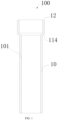
FIG. 1 is a schematic view of a pipeline connecting structure in an embodiment of the present invention. -
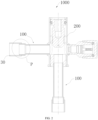
FIG. 2 is a schematic view of a stop valve in an embodiment of the present invention. -
FIG. 3 is an enlarged view of P part inFIG. 2 . -
FIG. 4 is a partial sectional view of a pipeline connecting structure in an embodiment of the present application. -
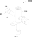
FIG. 5 is a schematic view of a stop valve in an embodiment of the present invention. -
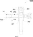
FIG. 6 is a sectional view of a stop valve in an embodiment of the present application. - In the figures, 1000 represents a stop valve; 100 represents a pipeline connecting structure; 10 represents a connecting pipe body; 101 represents an inner wall; 111 represents a solder blocking portion; 111a represents a first solder blocking portion; 111b represents a second solder blocking portion; 112 represents a first connecting section; 113 represents a second connecting section; 114 represents a first blocking section; 12 represents a groove; 20 represents a transition connecting pipe; 121 represents a switching blocking portion; 122 represents a first switching section; 123 represents a second switching section; 124 represents a second blocking section; 125 represents a guide inclined plane; 30 represents an external pipeline; 200 represents a valve body; 201 represents a first opening; 202 represents a second opening; 300 represents a valve seat; and 400 represents a valve core.
- The technical solutions in the embodiments of this application will be clearly and completely described below with reference to the accompanying drawings in the embodiments of this application. It is obvious that the described embodiments are only a part of the embodiments, but not all of the embodiments. All other embodiments obtained by a person of ordinary skill in the art based on the embodiments of the present application without creative efforts shall fall within the protection scope of the present application.
- It should be noted that when the component is referred to as being "mounted to" another component, it may be directly on the other component or may also be an intervening component. When one component is considered to be "disposed on" another component, it may be directly disposed on another component or there may be an intervening component simultaneously. When one component is considered to be "fixed to" another component, it may be directly fixed on another component or there may be an intervening component at the same time.
- Unless otherwise defined, all technical and scientific terms used herein have the same meaning as commonly understood by one skilled in the art to which this application belongs. The terminology used herein in the specification of the present application is for the purpose of describing particular embodiments only and is not intended to be limiting of the present application. As used herein, the terms "or/and" include any and all combinations of one or more of the associated listed items.
- A
pipeline connecting structure 100 in present application can play a role in blocking a flow of a solder. Thepipeline connecting structure 100 of the present application is specifically applied in astop valve 1000, so that thestop valve 1000 is welded and fixed with an external pipeline 30 (such as an air conditioning pipeline) through thepipeline connecting structure 100. It can prevent the excessive solder from flowing through thepipeline connecting structure 100 and entering thestop valve 1000 during welding, thereby preventing internal welding flow. Of course, thepipeline connecting structure 100 in present application is not limited to thestop valve 1000. For those skilled in the art, thepipeline connecting structure 100 can be applied to solenoid valves or other system pipelines, as long as it can play the same role, which will not be described here. - Referring to
FIG. 1 to FIG. 3 , in an embodiment, the present invention provides apipeline connecting structure 100. Thepipeline connecting structure 100 includes a connecting pipe body 10and asolder blocking portion 111 disposed on the connectingpipe body 10. - The
solder blocking portion 111 in the present invention can block a solder (not shown) from flowing on aninner wall 101 of the connectingpipe body 10, so as to restrict the solder from flowing out from an end of the connecting pipe body 10along a flow direction of the solder. That is, the connectingpipe body 10 of this embodiment can play a role of preventing an internal flow welding. Therefore, when the connectingpipe body 10 is applied to thestop valve 1000, the solder can be prevented from infiltrating into thevalve body 200. Furthermore, a normal assembly between other parts of thestop valve 1000 and thevalve body 200 is ensured. And at the same time, a blocking phenomenon of thestop valve 1000 caused by falling off of welding chips is avoided. It should be noted that the above-mentioned internal flow welding specifically means that the solder flows on theinner wall 101 of the connectingpipe body 10 and flows out from an end of the connectingpipe body 10. - It can be understood that through the above structural arrangement, the solder can be multiple restricted by the connecting
pipe body 10, which improves a barrier effect on the solder and further prevent an internal flow welding in the connectingpipe body 10. - In some embodiments, a plurality of the
solder blocking portions 111 are arranged at intervals, so that a preset gap is defined between adjacent two of thesolder blocking portions 111. In this way, the solder can be cooled as much as possible during a period from flowing through the previoussolder blocking portion 111 to a nextsolder blocking portion 111, thus further improving a blocking effect of the solder by the connectingpipe body 10. - Specifically, in this embodiment, the
solder blocking portion 111 includes a firstsolder blocking portion 111a and a secondsolder blocking portion 111b. The firstsolder blocking portion 111a is disposed on the inner wall of the connectingpipe body 10, and the second solder blocking portion 11 1b is disposed on an end of the connectingpipe body 10. - In this embodiment, the
solder blocking portion 111 is formed by a part of theinner wall 101 of the connectingpipe body 10 protruding in a direction of a center line of the connectingpipe body 10. In this way, through arrangement of thesolder blocking portion 111 on the connectingpipe body 10, the connectingpipe body 10 can use such protruding structure on theinner wall 101 of the connectingpipe body 10 to block the flow of the solder. - In some embodiments, along the flow direction of the solder, a part of the connecting
pipe body 10 is bent inward to form afirst blocking section 114, and a part of theinner wall 101 where thefirst blocking section 114 is located is regarded as thesolder blocking portion 111. In other words, the connectingpipe body 10 of this embodiment can use theinner wall 101 where thefirst blocking section 114 is located as thesolder blocking portion 111 to restrict the flow of the solder, so as to process and form thesolder blocking portion 111 on the connectingpipe body 10, which has a simplified structure and facilitates a production and preparation of the connectingpipe body 10. Of course, it should be noted that thesolder blocking portion 111 arranged on theinner wall 101 of the connectingpipe body 10 is not limited to illustration. For those skilled in the art, a protruding structure can also be directly arranged on theinner wall 101 of the connectingpipe body 10, which will not be described here. - Furthermore, a
groove 12 is disposed on an outer edge of an end of the connectingpipe body 10 in a direction opposite to the flow direction of the solder, and when the connectingpipe body 10 is inserted into anexternal pipeline 30, thegroove 12 of the connectingpipe body 10 is capable of fitting with theexternal pipeline 30 to form thesolder blocking portion 111. In other words, in this embodiment, thegroove 12 provided at the end of the connectingpipe body 10 can be used and regarded as thesolder blocking portion 111 for restricting the flow of the solder. So that the connectingpipe body 10 can use thegroove 12 to accommodate the solder flowing into the connectingpipe body 10 during operation, thereby achieving the purpose of blocking the solder from flowing. - It can be understood that the structural arrangement of the
solder blocking portion 111 on the connectingpipe body 10 can be realized in the above manners, so that the connectingpipe body 10 can choose to provide with thegroove 12 at the end of the connectingpipe body 10 as required, then thegroove 12 cooperates with theexternal pipeline 30 to achieve the purpose of blocking the solder. Furthermore, a structural diversity of setting the solder blocking portion on the connectingpipe body 10 is increased. - In this embodiment, the
groove 12 is in an annular shape, so as to meet the use requirements of welding and fixing with a welding ring during pipeline welding, and ensure that thegroove 12 disposed at the end of the connectingpipe body 10 can play a role in blocking the solder. - Furthermore, along the flow direction of the solder, the diameter of the
groove 12 gradually decreases, so as to facilitate the solder to enter thegroove 12 of the connectingpipe body 10 and cooperate with theexternal pipeline 30 to realize a barrier to the solder, which has an effect of further improving the barrier of thegroove 12 provided on the connectingpipe body 10 to the solder. - It can be understood that the number of the
first blocking section 114 for blocking the solder in thepipeline connecting structure 100 of the present invention is at least one, and the number of thegroove 12 for blocking the solder is one, which will not be described here. In other embodiments, thegroove 12 for blocking the solder or thefirst blocking section 114 for blocking the solder may be separately provided on thepipeline connecting structure 100. - In this embodiment, the
external pipeline 30 can be set as atransition connecting pipe 20, which is sleeved on the connectingpipe body 10 and welded and fixed with the connectingpipe body 10. The connectingpipe body 10 and thetransition connecting pipe 20 cooperate with each other to form thesolder blocking portion 111, which is used to block the solder when thetransition connecting pipe 20 is welded with other pipelines. - In an air conditioning system, the stop valve is used to cut off and throttle the medium in the pipeline where it is located.
- In a process of welding the stop valve and the air conditioning pipeline in the related art, when the solder used for welding melts and two pipelines are welded and fixed, excessive solder may flow along an inner wall of a pipeline and form internal flow welding, and even enter a valve cavity of the stop valve through the pipeline. In this way, it may not only affect the assembly of other parts in equipment, but also cause problems such as blockage caused by a fall of welding chips in subsequent use.
- To solve the above problem, referring to
FIG. 4 , in some embodiments, thepipeline connecting structure 100 further includes atransition connecting pipe 20. One end of thetransition connecting pipe 20 is connected with the connectingpipe body 10 and the other end of thetransition connecting pipe 20 is connected with theexternal pipeline 30. The connectingpipe body 10 is sleeved on thetransition connecting pipe 20, and the connectingpipe body 10 is provided with asolder blocking portion 111. Thetransition connecting pipe 20 is provided with aswitching blocking portion 121, thesolder blocking portion 111 and theswitching blocking portion 121 can prevent the solder from flowing on an inner wall of the connectingpipe body 10, so as to limit the solder from flowing out from the end of the connectingpipe body 10 away from thetransition connecting pipe 20. It can be understood that by providing the solder blocking portion and the switching blocking portion, the flow of the solder on thepipeline connecting structure 100 can be blocked. - Referring to
FIG. 4 , thesolder blocking portion 111 is formed by a part of the connectingpipe body 10 protruding towards a central axis of the connectingpipe body 10, so as to realize the arrangement of thesolder blocking portion 111 on the connectingpipe body 10. In this way, the structure is simple, and the processing is convenient, so that the connectingpipe body 10 can use such protruding structure on its inner wall to achieve the purpose of blocking the flow of the solder. - Furthermore, the connecting
pipe body 10 includes a first connectingsection 112, a second connectingsection 113 and afirst blocking section 114. The first connectingsection 112 is located at an end of the connectingpipe body 10 proximal to thetransition connecting pipe 20; The second connectingsection 113 is located at the end of the connectingpipe body 10 away from thetransition connecting pipe 20. Thefirst blocking section 114 is located between the first connectingsection 112 and the second connectingsection 113. And both ends of thefirst blocking section 114 are respectively connected with the first connectingsection 112 and the second connecting section 113.A diameter of the first connectingsection 112 is greater than a diameter of the second connectingsection 113. Along an axis of the connectingpipe body 10, a diameter of thefirst blocking section 114 gradually decreases from the first connectingsection 112 to the second connectingsection 113. In this way, it can play a role in blocking the flow of the solder and is convenient for processing. - Specifically, the
first blocking section 114 is regarded as thesolder blocking portion 111 that can block the flow of the solder, and a shape of thefirst blocking section 114 is substantially trumpet-shaped. In this way, the structure can be simplified and thefirst blocking section 114 can be processed conveniently. In addition, a connection between the connectingpipe body 10 and other components is facilitated by providing the first connectingsection 112 and the second connectingsection 113. - When one end of the
pipeline connecting structure 100 is welded to theexternal pipeline 30, a part of the solder will flow out from the other end of thepipeline connecting structure 100 after the solder melts. Therefore, in order to prevent an outflow of the solder, thetransition connecting pipe 20 is provided with aswitching blocking portion 121. Theswitching blocking portion 121 can prevent the solder from flowing on an inner wall of thetransition connecting pipe 20, and at the same time, the connectingpipe body 10 is provided with thesolder blocking portion 111, thesolder blocking portion 111 can block the flow of the solder on the inner wall of the connectingpipe body 10. Thus, with the cooperation of theswitching blocking portion 121 and thesolder blocking portion 111, the solder can be further prevented from flowing out from the end of the connectingpipe body 10 away from thetransition connecting pipe 20. - In particular, while the solder flows from the
switching blocking portion 121 of thetransition connecting pipe 20 to thesolder blocking portion 111 of the connectingpipe body 10, a path length of the solder flow is increased, so most of the solder will be cooled, which will further blocking the flow of the solder. That is, thepipeline connecting structure 100 is applied to thestop valve 1000, while welding between thepipeline connecting structure 100 and theexternal pipeline 30, a phenomenon that the solder flows into the valve cavity of thestop valve 1000 along the inner walls of thetransition connecting pipe 20 and the connectingpipe body 10 can be avoided, thus improving a performance of thestop valve 1000. - Referring to
FIG. 4 , theswitching blocking portion 121 is formed by a part of thetransition connecting pipe 20 protruding towards an axis of thetransition connecting pipe 20. Furthermore, by arrangement of theswitching blocking port 121 on thetransition connecting pipe 20, theswitching blocking port 121 has a simple structure and is convenient to process. And when thetransition connecting pipe 20 is in operation, it can use such protruding structure on its inner wall to achieve the purpose of blocking the flow of the solder. - Furthermore, the
transition connecting pipe 20 includes afirst switching section 122, asecond switching section 123 and asecond blocking section 124. Thefirst switching section 122 is located at an end of thetransition connecting pipe 20 away from the connectingpipe body 10. Thesecond switching section 123 is located at an end of thetransition connecting pipe 20 proximal to the connectingpipe body 10. Thesecond blocking section 124 is located between thefirst switching section 122 and thesecond switching section 123. And both ends of thesecond blocking section 124 are respectively connected with thefirst switching section 122 and thesecond switching section 123. A diameter of thefirst switching section 122 is greater than a diameter of thesecond switching section 123. Along an axis of thetransition connecting pipe 20, a diameter of thesecond blocking section 124 gradually decreases from thefirst switching section 122 to thesecond switching section 123. With this arrangement, the flow of the solder can be hindered and thetransition connecting pipe 20 can be processed conveniently. - Specifically, the
second blocking section 124 is regarded as theswitching blocking portion 121 that can block the flow of the solder, and a shape of thesecond blocking section 124 is substantially trumpet-shaped. In this way, a structure can be simplified and it is convenient to process thesecond blocking section 124. In addition, by providing thefirst switching section 122 and thesecond switching section 123, it is convenient to connect thetransition connecting pipe 20 with other components. - Referring to
FIG. 4 , the connectingpipe body 10 is sleeved outside thetransition connecting pipe 20, thetransition connecting pipe 20 extends into the connectingpipe body 10 and is restricted by and abuts against thesolder blocking portion 111. A blocking space of theswitching blocking portion 121 is greater than a blocking space of thesolder blocking portion 111, which can accommodate more redundant the solder. - Referring to
FIG. 4 , at least a part of thesecond switching section 123 extends into the first connectingsection 112 and abuts against thefirst blocking section 114. Thefirst blocking section 114 can not only block the flow of the solder, but also limit a length of thesecond switching section 123 extending into the first connectingsection 112, which is convenient for a rapid installation of thetransition connecting pipe 20. And an interconnection of thesecond switching section 123 and the first connectingsection 112 can improve a connecting strength between thetransition connecting pipe 20 and the connectingpipe body 10, thus improving a structural stability of thepipeline connecting structure 100. - The diameter of the first connecting
section 112 is equal to the diameter of thefirst switching section 122. It can be understood that if thetransition connecting pipe 20 is not provided, the first connectingsection 112 of the connectingpipe body 10 will be used to connect with theexternal pipeline 30. On the one hand, theswitching blocking portion 121 of thetransition connecting pipe 20 can block the solder to flow; on the other hand, thefirst switching section 122 on thetransition connecting pipe 20 can be used for welding with theexternal pipeline 30 instead of the connectingpipe body 10. Therefore, the diameter of the first connectingsection 112 is equal to the diameter of thefirst switching section 122, which can ensure a consistency of asize of thetransition connecting pipe 20 and a size of theexternal pipeline 30, thus facilitating an installation of thetransition connecting pipe 20 and theexternal pipeline 30. - Furthermore, the
transition connecting pipe 20 includes a guideinclined plane 125, which is arranged at an end of thetransition connecting pipe 20 away from the connectingpipe body 10. Specifically, the guide includedplane 125 is located at a side of thetransition connecting pipe 20 proximal to an axis of thetransition connecting pipe 20, and the guide includedplane 125 can play a role in improving guidance. It is convenient to guide theexternal pipeline 30 to be inserted into thetransition connecting pipeline 20, so as to prevent theexternal pipeline 30 from colliding with thetransition connecting pipeline 20 and being unable to be inserted smoothly, thereby improving the assembly efficiency of theexternal pipeline 30 and thetransition connecting pipeline 20. Of course, in other embodiments, besides the guideinclined plane 125, thetransition connecting pipe 20 can also be provided with other guiding structures, as long as the same effect can be achieved. - In some embodiments, the connecting
pipe body 10 is made of stainless-steel, and thetransition connecting pipe 20 is made of copper. The copper pipe is convenient to connect with theexternal pipeline 30 for welding, so as to meet the use requirements of thepipeline connecting structure 100 applied to thestop valve 1000. With such arrangement, a cost can be reduced. - In a technical field of refrigeration, copper pipes of the air conditioners are generally used as connecting pipes for connection. If the
transition connecting pipe 20 is not provided, copper pipe group needs to be welded with the connecting pipe body 10 (the connectingpipe body 10 is made of stainless-steel), but the welding characteristics of copper material and stainless-steel material are quite different. Therefore, it is difficult to directly weld the copper pipe group with the stainless-steel pipe. Therefore, thetransition connecting pipe 20 is made of red copper, and then the copper pipe group is directly welded with the red copper pipe, which makes the process simpler. - In addition, referring to
FIG. 2 ,FIG. 5 andFIG. 6 , the present application further provides astop valve 1000. Thestop valve 1000 includes avalve body 200 and apipeline connecting structure 100. Thepipeline connecting structure 100 is disposed on thevalve body 200, and thevalve body 200 is capable of installing on a system pipeline through thepipeline connecting structure 100. Thepipeline connecting structure 100 is mentioned as above. In this way, thestop valve 1000 has a function of preventing the solder from infiltrating into thevalve body 200, thus ensuring a normal assembly between other parts of thestop valve 1000 and thevalve body 200, and at the same time avoiding the subsequent blockage of thestop valve 1000 caused by a falling off of welding chips. - In the present invention, the connecting
pipe body 10 of thestop valve 1000 is provided with onefirst blocking section 114, and thegroove 12 is disposed at the end of the connectingpipe body 10 connected with thetransition connecting pipe 20. Thefirst blocking section 114 forms the firstsolder blocking portion 111a, and thegroove 12 forms the secondsolder blocking port 111b. It should be noted that, a distance a between the firstsolder blocking portion 111a and the secondsolder blocking portion 111b on the connectingpipe body 10 of thestop valve 1000 is greater than or equal to 0.5 mm and less than or equal to 5 mm, so that the solder can be cooled as much as possible before flowing through thegroove 12 and flowing to thefirst blocking section 114. - When the
pipeline connecting structure 100 provided by the present invention is applied to thestop valve 1000, thestop valve 1000 is welded and fixed with theexternal pipeline 30 through thepipeline connecting structure 100. It can prevent an excessive solder from flowing through thepipeline connecting structure 100 and entering a valve cavity of thestop valve 1000 in the welding process, thereby preventing internal welding flow, further ensuring the normal assembly between other parts of thestop valve 1000 and thevalve body 200, and avoiding a subsequent blockage of thestop valve 1000 caused by the falling off of welding chips. - Referring to
FIG. 6 , thevalve body 200 is provided with thefirst opening 201 and thesecond opening 202, and thefirst opening 201 is located at an end of thevalve body 200. Thesecond opening 202 is located at a peripheral side of thevalve body 200, and two of thepipeline connecting structures 100 are inserted into thefirst opening 201 and thesecond opening 202, respectively, thereby realizing a communication between the valve cavity of thevalve body 200 and theexternal pipeline 30. When thestop valve 1000 is turned on, a medium can flow into thevalve body 200 from thefirst opening 201 and flow out through thesecond opening 202. Alternatively, the medium can flow from thesecond opening 202 into thevalve body 200 and flow out through thefirst opening 201. - The
stop valve 1000 further includes avalve seat 300 and avalve core 400. Thevalve seat 300 is installed in thevalve body 200 through thefirst opening 201 and connected with thevalve body 200. Thevalve core 400 is located in thevalve body 200, and thevalve core 400 can move in thevalve body 200 to connect or disconnect thefirst opening 201 and thesecond opening 202. Thevalve seat 300 limits a movement of thevalve core 400. When thestop valve 1000 is in a closed state, thevalve core 400 abuts against thevalve seat 300 and cooperates with thevalve seat 300 to achieve sealing, thereby blocking a circulation of media between thefirst opening 201 and thesecond opening 202. When thestop valve 1000 is in an open state, thevalve core 400 is not in contact with thevalve seat 300, so that media can circulate between thefirst opening 201 and thesecond opening 202. - The
pipeline connecting structure 100 provided by the present invention can block the flow of the solder, thereby playing a role in avoiding the solder flow inward and improving the performance of thestop valve 1000. - The technical features of the above-mentioned embodiments can be combined arbitrarily. In order to make the description concise, not all possible combinations of the technical features are described in the embodiments. However, as long as there is no contradiction in the combination of these technical features, the combinations should be considered as in the scope of the present invention.
- One of ordinary skill in the art should recognize that the above embodiments are used only to illustrate the present invention and are not used to limit the present invention, and that appropriate variations and improvements to the above embodiments fall within the protection scope of the present invention so long as they are made without departing from the substantial spirit of the present invention.
Claims (15)
- A pipeline connecting structure, characterized by comprising a connecting pipe body, wherein the connecting pipe body is provided with a solder blocking portion, the solder blocking portion is capable of blocking a solder from flowing on an inner wall of the connecting pipe body, to limit the solder from flowing out from an end of the connecting pipe body along a flow direction of the solder.
- The pipeline connecting structure of claim 1, wherein the number of the solder blocking portions is multiple, and a plurality of solder blocking portions are arranged at intervals.
- The pipeline connecting structure of claim 2, wherein the solder blocking portion comprises a first solder blocking portion and a second solder blocking portion, the first solder blocking portion is disposed on an inner wall of the connecting pipe body, the second solder blocking portion is disposed on an end of the connecting pipe body, a distance between the first solder blocking port and the second solder blocking port is defined as a, and the distance a between the first solder blocking portion and the second solder blocking portion satisfies following formula: 0.5 mm ≤a ≤5 mm .
- The pipeline connecting structure of claims 1 or 2, wherein the solder blocking portion is defined by a part of the inner wall of the connecting pipe body protruding in a direction of a center line of the connecting pipe body; and/or,
a first blocking section is defined by a part of the connecting pipe body being bent inward along the flow direction of the solder, and the solder blocking portion is a part of the inner wall of the connecting pipe body where the first blocking section is located. - The pipeline connecting structure of claims 1 or 2, wherein a groove is defined on an outer edge of an end of the connecting pipe body in a direction opposite to the flow direction of the solder, and when the connecting pipe body is inserted into an external pipeline, the groove of the connecting pipe body is capable of fitting with the external pipeline to form the solder blocking portion.
- The pipeline connecting structure of claim 5, wherein the groove is in an annular shape and a diameter of the groove gradually decreases along the flow direction of the solder.
- The pipeline connecting structure of claim 5, further comprising a transition connecting pipe, wherein the transition connecting pipe is sleeved on the connecting pipe body and welded and fixed with the connecting pipe body.
- The pipeline connecting structure of claim 1, further comprising a transition connecting pipe, wherein one end of the transition connecting pipe is connected with the connecting pipe body and the other end of the transition connecting pipe is connected with an external pipeline;
the connecting pipe body is sleeved on the transition connecting pipe, and the connecting pipe body is provided with the solder blocking portion; the transition connecting pipe is provided with a switching blocking portion, the solder blocking portion and the switching blocking portion are capable of blocking the solder from flowing on the inner wall of the connecting pipe body, so as to limit the solder from flowing out from an end of the connecting pipe body away the transition connecting pipe. - The pipeline connecting structure of claim 8, wherein the solder blocking portion is formed by a part of the connecting pipe body protruding towards an axis of the connecting pipe body.
- The pipeline connecting structure of claims 8 or 9, wherein the connecting pipe body comprises:a first connecting section, wherein the first connecting section is located at an end of the connecting pipe body proximal to the transition connecting pipe;a second connecting section, wherein the second connecting section is located at an end of the connecting pipe body away from the transition connecting pipe; anda first blocking section, wherein the first blocking section is located between the first connecting section and the second connecting section, and two ends of the first blocking section are respectively connected with the first connecting section and the second connecting section,wherein a diameter of the first connecting section is greater than a diameter of the second connecting section, and along an axis of the connecting pipe body, a diameter of the first blocking section gradually decreases from the first connecting section to the second connecting section; and/or,the transition connecting pipe comprises a guide inclined plane, and the guide inclined plane is arranged at an end of the transition connecting pipe away from the connecting pipe body.
- The pipeline connecting structure of claim 10, wherein the switching blocking portion is formed by a part of the transition connecting pipe protruding towards an axis of the transition connecting pipe.
- The pipeline connecting structure of claim 11, wherein the transition connecting pipe comprises:a first switching section, wherein the first switching section is located at an end of the transition connecting pipe away from the connecting pipe body;a second switching section, wherein the second switching section is located at an end of the transition connecting pipe proximal to the connecting pipe body; anda second blocking section, wherein the second blocking section is located between the first switching section and the second switching section, and two ends of the second blocking section are respectively connected with the first switching section and the second switching section;wherein a diameter of the first switching section is greater than a diameter of the second switching section, and along an axial direction of the transition connecting pipe, a diameter of the second blocking section gradually decreases from the first switching section to the second switching section.
- The pipeline connecting structure of claim 12, wherein at least a part of the second switching section extends into the first connecting section and abuts against the first blocking section, and the second switching section and the first connecting section are connected with each other;
the diameter of the first connecting section is equal to the diameter of the first switching section. - The pipeline connecting structure of claims 7 or 8, wherein the connecting pipe body is made of stainless-steel and the transition connecting pipe is made of copper.
- A stop valve, comprising a valve body and a pipeline connecting structure, wherein the pipeline connecting structure is disposed on the valve body, and the valve body is capable of installing on a system pipeline through the pipeline connecting structure; characterized in that, the pipeline connecting structure is the pipeline connecting structure of any one of claims 1 to 14.
Applications Claiming Priority (3)
| Application Number | Priority Date | Filing Date | Title |
|---|---|---|---|
| CN202122892491.3U CN216743126U (en) | 2021-11-22 | 2021-11-22 | Pipeline connection structure and stop valve |
| CN202221673170.2U CN217977612U (en) | 2022-06-30 | 2022-06-30 | Pipe connection structure and stop valve |
| PCT/CN2022/133042 WO2023088452A1 (en) | 2021-11-22 | 2022-11-19 | Pipeline connecting structure and stop valve |
Publications (2)
| Publication Number | Publication Date |
|---|---|
| EP4435305A1 true EP4435305A1 (en) | 2024-09-25 |
| EP4435305A4 EP4435305A4 (en) | 2025-03-05 |
Family
ID=86396300
Family Applications (1)
| Application Number | Title | Priority Date | Filing Date |
|---|---|---|---|
| EP22894981.4A Pending EP4435305A4 (en) | 2021-11-22 | 2022-11-19 | PIPE CONNECTION STRUCTURE AND SHUT-OFF VALVE |
Country Status (4)
| Country | Link |
|---|---|
| EP (1) | EP4435305A4 (en) |
| JP (1) | JP2024541258A (en) |
| KR (1) | KR20240099424A (en) |
| WO (1) | WO2023088452A1 (en) |
Family Cites Families (14)
| Publication number | Priority date | Publication date | Assignee | Title |
|---|---|---|---|---|
| JPS5297926U (en) * | 1976-01-22 | 1977-07-23 | ||
| JPH08267228A (en) * | 1995-03-28 | 1996-10-15 | Nippon Light Metal Co Ltd | Joint structure of aluminum pipe and copper pipe |
| JP2005076842A (en) * | 2003-09-03 | 2005-03-24 | Fuji Koki Corp | Motorized valve |
| JP5633205B2 (en) * | 2010-06-17 | 2014-12-03 | 富士電機株式会社 | Joining method and joining structure of aluminum tube and copper tube, and heat exchanger having this joining structure |
| CN102128323B (en) * | 2011-03-01 | 2012-07-18 | Tcl空调器(中山)有限公司 | Connection structure of copper-aluminum composite pipe and copper pipe and welding method thereof |
| DE102012005198B4 (en) * | 2012-03-16 | 2017-05-11 | Tenneco Gmbh | Pipe connection with slotted tube wall end and method for its production |
| CN104015019A (en) * | 2014-05-29 | 2014-09-03 | 浙江三花制冷集团有限公司 | Air header component manufacturing method and heat exchanger using air header component |
| CN204842717U (en) * | 2015-06-29 | 2015-12-09 | 河南新科隆电器有限公司 | Pipe welding structure |
| CN207394200U (en) * | 2017-10-27 | 2018-05-22 | 新昌县华亿机械有限公司 | A kind of air-conditioning tube assembly |
| JP6635146B2 (en) * | 2018-06-18 | 2020-01-22 | ダイキン工業株式会社 | Shut-off valve |
| JP6604416B1 (en) * | 2018-10-22 | 2019-11-13 | 三菱重工冷熱株式会社 | Piping connection structure |
| CN110936042B (en) * | 2019-10-30 | 2022-07-19 | 中国电器科学研究院股份有限公司 | Copper pipe welding method |
| CN213299112U (en) * | 2019-12-20 | 2021-05-28 | 新昌县四通机电有限公司 | Header part |
| CN216743126U (en) * | 2021-11-22 | 2022-06-14 | 浙江盾安人工环境股份有限公司 | Pipeline connection structure and stop valve |
-
2022
- 2022-11-19 JP JP2024525588A patent/JP2024541258A/en active Pending
- 2022-11-19 WO PCT/CN2022/133042 patent/WO2023088452A1/en not_active Ceased
- 2022-11-19 EP EP22894981.4A patent/EP4435305A4/en active Pending
- 2022-11-19 KR KR1020247018639A patent/KR20240099424A/en active Pending
Also Published As
| Publication number | Publication date |
|---|---|
| WO2023088452A1 (en) | 2023-05-25 |
| JP2024541258A (en) | 2024-11-08 |
| EP4435305A4 (en) | 2025-03-05 |
| KR20240099424A (en) | 2024-06-28 |
Similar Documents
| Publication | Publication Date | Title |
|---|---|---|
| KR102668677B1 (en) | Electronic expansion valve | |
| EP1837565A1 (en) | Four-way valve | |
| EP4450855A1 (en) | Stop valve and refrigeration system having same | |
| EP4435305A1 (en) | Pipeline connecting structure and stop valve | |
| JP2025517874A (en) | Stop valves and air conditioning systems | |
| CN217381640U (en) | Stop valve and refrigerating system thereof | |
| JP7577193B2 (en) | Stop valve and air conditioning system having same | |
| KR20230096117A (en) | One-way valve and air conditioner equipped with the same | |
| EP4624786A1 (en) | Sliding block assembly, valve, and air conditioning system | |
| CN216743126U (en) | Pipeline connection structure and stop valve | |
| US12366417B2 (en) | Heat exchange device | |
| CN212253247U (en) | Air conditioner and throttle valve thereof | |
| CN217977612U (en) | Pipe connection structure and stop valve | |
| CN223004491U (en) | One-way valve, heating and ventilation equipment outdoor unit and heating and ventilation equipment | |
| JP7855146B2 (en) | Switching valves and air conditioning systems | |
| CN222458505U (en) | Throttle valve | |
| JP2025536594A (en) | Switching valves and air conditioning systems | |
| CN117917518A (en) | A control valve |
Legal Events
| Date | Code | Title | Description |
|---|---|---|---|
| STAA | Information on the status of an ep patent application or granted ep patent |
Free format text: STATUS: THE INTERNATIONAL PUBLICATION HAS BEEN MADE |
|
| PUAI | Public reference made under article 153(3) epc to a published international application that has entered the european phase |
Free format text: ORIGINAL CODE: 0009012 |
|
| STAA | Information on the status of an ep patent application or granted ep patent |
Free format text: STATUS: REQUEST FOR EXAMINATION WAS MADE |
|
| 17P | Request for examination filed |
Effective date: 20240620 |
|
| AK | Designated contracting states |
Kind code of ref document: A1 Designated state(s): AL AT BE BG CH CY CZ DE DK EE ES FI FR GB GR HR HU IE IS IT LI LT LU LV MC ME MK MT NL NO PL PT RO RS SE SI SK SM TR |
|
| REG | Reference to a national code |
Ref country code: DE Ref legal event code: R079 Free format text: PREVIOUS MAIN CLASS: F16L0001000000 Ipc: F16L0013020000 |
|
| DAV | Request for validation of the european patent (deleted) | ||
| DAX | Request for extension of the european patent (deleted) | ||
| A4 | Supplementary search report drawn up and despatched |
Effective date: 20250130 |
|
| RIC1 | Information provided on ipc code assigned before grant |
Ipc: F25B 1/00 20060101ALI20250124BHEP Ipc: F16L 13/08 20060101ALI20250124BHEP Ipc: F16L 13/02 20060101AFI20250124BHEP |