EP4435291A1 - Vehicle drive device and production method for planetary gear mechanism - Google Patents
Vehicle drive device and production method for planetary gear mechanism Download PDFInfo
- Publication number
- EP4435291A1 EP4435291A1 EP23780433.1A EP23780433A EP4435291A1 EP 4435291 A1 EP4435291 A1 EP 4435291A1 EP 23780433 A EP23780433 A EP 23780433A EP 4435291 A1 EP4435291 A1 EP 4435291A1
- Authority
- EP
- European Patent Office
- Prior art keywords
- gear
- planetary gears
- teeth
- gear portion
- planetary
- Prior art date
- Legal status (The legal status is an assumption and is not a legal conclusion. Google has not performed a legal analysis and makes no representation as to the accuracy of the status listed.)
- Granted
Links
Images



Classifications
-
- H—ELECTRICITY
- H02—GENERATION; CONVERSION OR DISTRIBUTION OF ELECTRIC POWER
- H02K—DYNAMO-ELECTRIC MACHINES
- H02K7/00—Arrangements for handling mechanical energy structurally associated with dynamo-electric machines, e.g. structural association with mechanical driving motors or auxiliary dynamo-electric machines
- H02K7/10—Structural association with clutches, brakes, gears, pulleys or mechanical starters
- H02K7/116—Structural association with clutches, brakes, gears, pulleys or mechanical starters with gears
-
- F—MECHANICAL ENGINEERING; LIGHTING; HEATING; WEAPONS; BLASTING
- F16—ENGINEERING ELEMENTS AND UNITS; GENERAL MEASURES FOR PRODUCING AND MAINTAINING EFFECTIVE FUNCTIONING OF MACHINES OR INSTALLATIONS; THERMAL INSULATION IN GENERAL
- F16H—GEARING
- F16H37/00—Combinations of mechanical gearings, not provided for in groups F16H1/00 - F16H35/00
- F16H37/02—Combinations of mechanical gearings, not provided for in groups F16H1/00 - F16H35/00 comprising essentially only toothed or friction gearings
- F16H37/06—Combinations of mechanical gearings, not provided for in groups F16H1/00 - F16H35/00 comprising essentially only toothed or friction gearings with a plurality of driving or driven shafts; with arrangements for dividing torque between two or more intermediate shafts
- F16H37/08—Combinations of mechanical gearings, not provided for in groups F16H1/00 - F16H35/00 comprising essentially only toothed or friction gearings with a plurality of driving or driven shafts; with arrangements for dividing torque between two or more intermediate shafts with differential gearing
- F16H37/0806—Combinations of mechanical gearings, not provided for in groups F16H1/00 - F16H35/00 comprising essentially only toothed or friction gearings with a plurality of driving or driven shafts; with arrangements for dividing torque between two or more intermediate shafts with differential gearing with a plurality of driving or driven shafts
- F16H37/0813—Combinations of mechanical gearings, not provided for in groups F16H1/00 - F16H35/00 comprising essentially only toothed or friction gearings with a plurality of driving or driven shafts; with arrangements for dividing torque between two or more intermediate shafts with differential gearing with a plurality of driving or driven shafts with only one input shaft
- F16H37/082—Combinations of mechanical gearings, not provided for in groups F16H1/00 - F16H35/00 comprising essentially only toothed or friction gearings with a plurality of driving or driven shafts; with arrangements for dividing torque between two or more intermediate shafts with differential gearing with a plurality of driving or driven shafts with only one input shaft and additional planetary reduction gears
-
- B—PERFORMING OPERATIONS; TRANSPORTING
- B60—VEHICLES IN GENERAL
- B60K—ARRANGEMENT OR MOUNTING OF PROPULSION UNITS OR OF TRANSMISSIONS IN VEHICLES; ARRANGEMENT OR MOUNTING OF PLURAL DIVERSE PRIME-MOVERS IN VEHICLES; AUXILIARY DRIVES FOR VEHICLES; INSTRUMENTATION OR DASHBOARDS FOR VEHICLES; ARRANGEMENTS IN CONNECTION WITH COOLING, AIR INTAKE, GAS EXHAUST OR FUEL SUPPLY OF PROPULSION UNITS IN VEHICLES
- B60K1/00—Arrangement or mounting of electrical propulsion units
-
- B—PERFORMING OPERATIONS; TRANSPORTING
- B60—VEHICLES IN GENERAL
- B60K—ARRANGEMENT OR MOUNTING OF PROPULSION UNITS OR OF TRANSMISSIONS IN VEHICLES; ARRANGEMENT OR MOUNTING OF PLURAL DIVERSE PRIME-MOVERS IN VEHICLES; AUXILIARY DRIVES FOR VEHICLES; INSTRUMENTATION OR DASHBOARDS FOR VEHICLES; ARRANGEMENTS IN CONNECTION WITH COOLING, AIR INTAKE, GAS EXHAUST OR FUEL SUPPLY OF PROPULSION UNITS IN VEHICLES
- B60K17/00—Arrangement or mounting of transmissions in vehicles
- B60K17/04—Arrangement or mounting of transmissions in vehicles characterised by arrangement, location or kind of gearing
- B60K17/16—Arrangement or mounting of transmissions in vehicles characterised by arrangement, location or kind of gearing of differential gearing
- B60K17/165—Arrangement or mounting of transmissions in vehicles characterised by arrangement, location or kind of gearing of differential gearing provided between independent half axles
-
- F—MECHANICAL ENGINEERING; LIGHTING; HEATING; WEAPONS; BLASTING
- F16—ENGINEERING ELEMENTS AND UNITS; GENERAL MEASURES FOR PRODUCING AND MAINTAINING EFFECTIVE FUNCTIONING OF MACHINES OR INSTALLATIONS; THERMAL INSULATION IN GENERAL
- F16H—GEARING
- F16H1/00—Toothed gearings for conveying rotary motion
- F16H1/28—Toothed gearings for conveying rotary motion with gears having orbital motion
- F16H1/46—Systems consisting of a plurality of gear trains each with orbital gears, i.e. systems having three or more central gears
-
- F—MECHANICAL ENGINEERING; LIGHTING; HEATING; WEAPONS; BLASTING
- F16—ENGINEERING ELEMENTS AND UNITS; GENERAL MEASURES FOR PRODUCING AND MAINTAINING EFFECTIVE FUNCTIONING OF MACHINES OR INSTALLATIONS; THERMAL INSULATION IN GENERAL
- F16H—GEARING
- F16H57/00—General details of gearing
- F16H57/0006—Vibration-damping or noise reducing means specially adapted for gearings
-
- B—PERFORMING OPERATIONS; TRANSPORTING
- B60—VEHICLES IN GENERAL
- B60K—ARRANGEMENT OR MOUNTING OF PROPULSION UNITS OR OF TRANSMISSIONS IN VEHICLES; ARRANGEMENT OR MOUNTING OF PLURAL DIVERSE PRIME-MOVERS IN VEHICLES; AUXILIARY DRIVES FOR VEHICLES; INSTRUMENTATION OR DASHBOARDS FOR VEHICLES; ARRANGEMENTS IN CONNECTION WITH COOLING, AIR INTAKE, GAS EXHAUST OR FUEL SUPPLY OF PROPULSION UNITS IN VEHICLES
- B60K1/00—Arrangement or mounting of electrical propulsion units
- B60K2001/001—Arrangement or mounting of electrical propulsion units one motor mounted on a propulsion axle for rotating right and left wheels of this axle
-
- F—MECHANICAL ENGINEERING; LIGHTING; HEATING; WEAPONS; BLASTING
- F16—ENGINEERING ELEMENTS AND UNITS; GENERAL MEASURES FOR PRODUCING AND MAINTAINING EFFECTIVE FUNCTIONING OF MACHINES OR INSTALLATIONS; THERMAL INSULATION IN GENERAL
- F16H—GEARING
- F16H1/00—Toothed gearings for conveying rotary motion
- F16H1/28—Toothed gearings for conveying rotary motion with gears having orbital motion
Definitions
- the present invention relates to vehicle drive devices and methods for manufacturing a planetary gear mechanism.
- a vehicle drive device has been used that includes: a rotating electrical machine; a pair of output members drivingly connected to wheels; a speed reducer that reduces the speed of rotation of a rotor; and a differential gear mechanism that distributes the rotation of the rotor transmitted via the speed reducer to the pair of output members.
- a rotating electrical machine includes: a rotating electrical machine; a pair of output members drivingly connected to wheels; a speed reducer that reduces the speed of rotation of a rotor; and a differential gear mechanism that distributes the rotation of the rotor transmitted via the speed reducer to the pair of output members.
- the vehicle drive device (drive device for an electric vehicle) of Patent Document 1 includes, as a speed reducer (speed reduction device 3), a planetary gear mechanism including a carrier (carrier C) that rotatably supports planetary gears each including a first gear portion (first planetary gear P1) and a second gear portion (second planetary gear P2) having a different number of teeth from the first gear portion.
- a speed reducer speed reduction device 3
- a planetary gear mechanism including a carrier (carrier C) that rotatably supports planetary gears each including a first gear portion (first planetary gear P1) and a second gear portion (second planetary gear P2) having a different number of teeth from the first gear portion.
- the planetary gear mechanism that constitutes the speed reducer includes: a gear (sun gear S 1) meshing with the first gear portions and connected to a rotor so as to rotate with the rotor; a gear (first ring gear R1) meshing with the first gear portions and fixed to a non-rotating member (housing 1); and a gear (second ring gear R2) meshing with the second gear portions and connected to an input element (ring gear DR) of a differential gear mechanism (differential 4) so as to rotate with the input element (ring gear DR).
- the vehicle drive device of Patent Document 1 achieves reduction in weight and cost by using the speed reducer having such a configuration.
- Patent Document 1 Japanese Unexamined Patent Application Publication No. 2002-104001 ( JP 2002-104001 A )
- a vehicle drive device is a vehicle drive device including: an input member drivingly connected to a driving source; and a speed reducer that reduces a speed of rotation of the input member and outputs resultant rotation to an output member drivingly connected to a wheel.
- the speed reducer includes a planetary gear mechanism, the planetary gear mechanism including 2N (where N represents an integer of 2 or more) planetary gears each including a first gear portion and a second gear portion having a different number of teeth from the first gear portion, and a carrier that rotatably supports each of the 2N planetary gears.
- the 2N planetary gears are arranged at equal intervals in a circumferential direction.
- Meshing phases of circumferentially adjacent ones of the planetary gears are opposite to each other.
- the numbers of teeth of all gears that mesh with the first gear portion and the second gear portion in the planetary gear mechanism are values whose remainder is N when divided by 2N.
- the 2N planetary gears include N first type planetary gears and N second type planetary gears.
- the first type planetary gears and the second type planetary gears are different from each other in phase of gear teeth of the second gear portion with respect to gear teeth of the first gear portion.
- the first type planetary gears and the second type planetary gears are arranged alternately in the circumferential direction.
- radial forces generated by meshing of the gears can be cancelled out by the N first type planetary gears and the N second type planetary gears, so that the sum of the radial forces can be reduced to close to zero.
- tangential moments acting on meshing portions of the gears can be canceled out by the N first type planetary gears and the N second type planetary gears, so that the sum of the tangential motions can be reduced to close to zero.
- This can reduce radial vibration around the rotation axis of the carrier and can also reduce torsional vibration around the rotation axis of the carrier. Based on these, it is possible to implement the vehicle drive device with reduced gear noise.
- a method for manufacturing a planetary gear mechanism according to the present disclosure is a method for manufacturing a planetary gear mechanism including 2N (where N represents an integer of 2 or more) planetary gears each including a first gear portion and a second gear portion having a different number of teeth from the first gear portion, and a carrier that rotatably supports each of the 2N planetary gears.
- the method includes: setting the numbers of teeth of all gears that mesh with the first gear portion and the second gear portion to values whose remainder is N when divided by 2N; preparing N first type planetary gears and N second type planetary gears as the 2N planetary gears such that a phase of gear teeth of the second gear portion with respect to gear teeth of the first gear portion is different by a predetermined set phase difference between the first type planetary gears and the second type planetary gears; arranging the 2N planetary gears at equal intervals in a circumferential direction and arranging the first type planetary gears and the second type planetary gears alternately in the circumferential direction; and setting the set phase difference to an angular difference on a planetary gear axis corresponding to a difference between an angle obtained by dividing 180° by the number of teeth of a ring gear that meshes with the first gear portion and an angle obtained by dividing 180° by the number of teeth of the ring gear that meshes with the second gear portion, or an angular difference on the
- the first gear portions and the second gear portions of the 2N planetary gears are allowed to appropriately mesh with their corresponding gears, which facilitates assembly of these gears.
- Radial forces generated by meshing of the gears can be cancelled out by the N first type planetary gears and the N second type planetary gears, so that the sum of the radial forces can be reduced to close to zero.
- tangential moments acting on meshing portions of the gears can be canceled out by the N first type planetary gears and the N second type planetary gears, so that the sum of the tangential motions can be reduced to close to zero.
- This can reduce radial vibration around the rotation axis of the carrier and can also reduce torsional vibration around the rotation axis of the carrier. Based on these, it is possible to manufacture the planetary gear mechanism with reduced gear noise.
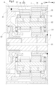
- a vehicle drive device 1 includes a rotating electrical machine 2, a speed reducer 3, a differential gear mechanism 4, and output members 5 drivingly connected to wheels W. These are housed in a case (drive device case) 7.
- drivingly connected refers to a state in which two rotating elements are connected such that a driving force (synonymous with torque) can be transmitted.
- This concept includes a state in which the two rotating elements are connected so as to rotate together and a state in which the two rotating elements are connected such that a driving force can be transmitted via one or more transmission members.
- Such transmission members include various members that transmit rotation at the same speed or at a changed speed (e.g., a shaft, a gear mechanism, a belt, etc.), and may include engagement devices that selectively transmit rotation and a driving force (e.g., a friction engagement device, a meshing type engagement device, etc.).
- the "rotating electrical machine” is used as a concept including a motor (electric motor), a generator (power generator), and a motor generator that functions as both a motor and a generator as necessary.
- the rotating electrical machine 2 (rotor 22), the speed reducer 3, and the differential gear mechanism 4 are arranged coaxially.
- axial direction L the direction along a common rotation axis of these components
- first side L 1 in the axial direction One side in the axial direction L
- second side L2 in the axial direction One side in the axial direction L
- the rotating electrical machine 2 (rotor 22), the speed reducer 3, and the differential gear mechanism 4 are arranged in this order from the first side L 1 in the axial direction to the second side L2 in the axial direction.
- the rotating electrical machine 2 be the rotating electrical machine 2 including the rotor 22 connected to a rotor shaft 25 so as to rotate with the rotor shaft 25, the pair of output members 5 be provided
- the vehicle drive device further include the differential gear mechanism 4 that distributes rotation of the rotor 22 transmitted via the speed reducer 3 to the pair of output members 5, the rotor 22, the speed reducer 3, and the differential gear mechanism 4 be arranged coaxially, and the rotor 22, the speed reducer 3, and the differential gear mechanism 4 be arranged in this order from the first side L 1 in the axial direction to the second side L2 in the axial direction, the axial direction L being the direction along the rotation axis of the rotor 22, the first side L1 in the axial direction being one side in the axial direction L, and the second side L2 in the axial direction being the other side in the axial direction L.
- the rotating electrical machine 2, the speed reducer 3, and the differential gear mechanism 4 are arranged coaxially, which facilitates reduction in size, particularly radial dimension, of the vehicle drive device 1.
- the rotating electrical machine 2 functions as a driving force source for the wheels W.
- the rotating electrical machine 2 includes a stator 21 fixed to the case 7 that is a non-rotating member, and the rotor 22 rotatably supported radially inside the stator 21.
- the rotating electrical machine 2 is supplied with electric power from an energy storage device (not shown) to perform power running, or supplies electric power generated by the inertial force of the vehicle etc. to the energy storage device to store the electric power in the energy storage device.
- the rotor 22 of the rotating electrical machine 2 is connected to the rotor shaft 25 so as to rotate with the rotor shaft 25.
- the rotating electrical machine 2 corresponds to the "driving source”
- the rotor shaft 25 corresponds to the "input member.”
- the rotor shaft 25 extends from the rotor 22 toward the second side L2 in the axial direction.
- a sun gear 31 of a planetary gear mechanism 30 that constitutes the speed reducer 3 is connected to an end on the second side L2 in the axial direction of the rotor shaft 25 so as to rotate with the rotor shaft 25.
- the speed reducer 3 reduces the speed of rotation of the rotor 22.
- the speed reducer 3 of the present embodiment includes the planetary gear mechanism 30.
- the planetary gear mechanism 30 constituting the speed reducer 3 includes four rotating elements: the sun gear 31, a carrier 32, a first ring gear 36, and a second ring gear 37.
- the sun gear 31 is an input rotating element of the speed reducer 3, and is connected to the rotor shaft 25 and the rotor 22 so as to rotate with the rotor shaft 25 and the rotor 22.
- the first ring gear 36 is fixed to the case 7 that is a non-rotating member.
- the second ring gear 37 is an output rotating element of the speed reducer 3, and is connected to a differential case 41 of the differential gear mechanism 4 so as to rotate with the differential case 41.
- the carrier 32 rotatably supports each of a plurality of planetary gears 33 each integrally including a first gear portion 34 that meshes with the sun gear 31 and the first ring gear 36 and a second gear portion 35 that meshes with the second ring gear 37.
- the rotating electrical machine 2 be the rotating electrical machine 2 including the rotor 22 connected to the rotor shaft 25 so as to rotate with the rotor shaft 25, the pair of output members 5 be provided
- the vehicle drive device further include the differential gear mechanism 4 that distributes rotation of the rotor 22 transmitted via the speed reducer 3 to the pair of output members 5,
- the speed reducer 3 further include the sun gear 31 and the first ring gear 36 that mesh with the first gear portion 34, and the second ring gear 37 that meshes with the second gear portion 35
- the sun gear 31 be connected to the rotor 22 so as to rotate with the rotor 22,
- the first ring gear 36 be fixed to the case 7, and the second ring gear 37 be connected to the differential case 41 of the differential gear mechanism 4 so as to rotate with the differential case 41.
- the speed reducer 3 having a relatively simple configuration can reduce the speed of rotation of the rotor 22 at a relatively high reduction ratio and transmit the resultant rotation to the differential gear mechanism 4. This facilitates reduction in size and weight of the vehicle drive device 1.
- the carrier 32 rotates about a carrier axis X1.
- the carrier axis X1 is also the rotation axis of the speed reducer 3, and is a common rotation axis of the rotating electrical machine 2 (rotor 22) and the differential gear mechanism 4.
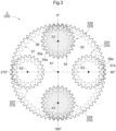
- the plurality of planetary gears 33 rotates (turns) about individual planetary gear axes X2 and rotates (revolves) around the carrier axis X1 together with the carrier 32 (see FIG. 3 ).
- the first gear portion 34 and the second gear portion 35 of each planetary gear 33 are formed with different outer diameters from each other and have different numbers of teeth from each other.
- the first gear portion 34 is formed with a larger diameter than the second gear portion 35, and the number of teeth of the first gear portion 34 is set to be larger than that of the second gear portion 35.
- the differential case 41 connected to the second ring gear 37 so as to rotate with the second ring gear 37 is an input rotating element of the differential gear mechanism 4.
- the differential case 41 corresponds to the "input member.”
- the differential gear mechanism 4 includes the differential case 41 and a differential body 42.
- the differential body 42 includes a plurality of bevel gears (e.g., pinion gears and side gears) that meshes with each other, and is responsible for a differential operation.
- the pair of output members 5 is drivingly connected to the differential gear mechanism 4.
- the differential gear mechanism 4 distributes rotation of the rotor 22 transmitted via the speed reducer 3 to the pair of output members 5.
- the pair of output members 5 is drivingly connected to the wheels W.
- the output member 5 on the first side L1 in the axial direction is disposed radially inward of the speed reducer 3 and the rotating electrical machine 2 so as to extend through the speed reducer 3 and the rotating electrical machine 2, and is drivingly connected to the wheel W at a position on the first side L1 in the axial direction with respect to the rotating electrical machine 2.
- One feature of the vehicle drive device 1 of the present embodiment is setting of the numbers of teeth of the sun gear 31, the first ring gear 36, and the second ring gear 37 in relation to the number of planetary gears 33 supported by the carrier 32 of the planetary gear mechanism 30 constituting the speed reducer 3.
- another feature is that the plurality of planetary gears 33 supported by the carrier 32 includes two different types of planetary gears, rather than being consisting of a single type of planetary gears as is often the case. This will be described below.
- the number of planetary gears 33 supported by the carrier 32 of the present embodiment is an even number of 4 or more. That is, each of 2N planetary gears 33 is rotatably supported by the carrier 32, where the symbol "N" is an integer of 2 or more.
- the numbers of teeth of all the gears that mesh with the first gear portions 34 and the second gear portions 35 in the planetary gear mechanism 30 are set to values whose remainder is N when divided by 2N.
- circumferentially adjacent ones of the planetary gears 33 mesh with a half tooth offset, and circumferentially opposing ones of the planetary gears 33 mesh at the same time.
- the meshing phases of circumferentially adjacent ones of the planetary gears 33 are opposite to each other, and the meshing phases of circumferentially opposing ones of the planetary gears 33 are the same.
- two upper and lower planetary gears 33 mesh with a gear tooth 34a of the first gear portion 34 being engaged in a valley of the first ring gear 36 and with a gear tooth 35a of the second gear portion 35 being engaged in a valley of the second ring gear 37 at 0° and 180° positions.
- two right and let planetary gears 33 mesh with a gear tooth 36a of the first ring gear 36 being engaged in a valley of the first gear portion 34 and a gear tooth 37a of the second ring gear 37 being engaged in a valley of the second gear portion 35 at 90° and 270° positions.
- the planetary gear mechanism 30 constituting the speed reducer 3 includes, as the 2N planetary gears 33, N first type planetary gears 33X and N second type planetary gears 33Y different from the first type planetary gears 33X.
- the first type planetary gear 33X and the second type planetary gear 33Y are the same in specifications (pitch diameter, number of teeth, etc.) of the gear teeth 34a of the first gear portion 34 and specifications of the gear teeth 35a of the second gear portion 35, and are different only in phase of the gear teeth 35a of the second gear portion 35 with respect to the gear teeth 34a of the first gear portion 34.
- phase difference ⁇ The difference between the phase of the gear teeth 35a of the second gear portion 35 with respect to the gear teeth 34a of the first gear portion 34 of the first type planetary gear 33X and the phase of the gear teeth 35a of the second gear portion 35 with respect to the gear teeth 34a of the first gear portion 34 of the second type planetary gear 33Y is referred to as "phase difference ⁇ ."
- phase difference ⁇ the difference between the phase of the gear teeth 35a of the second gear portion 35 with respect to the gear teeth 34a of the first gear portion 34 of the first type planetary gear 33X and the phase of the gear teeth 35a of the second gear portion 35 with respect to the gear teeth 34a of the first gear portion 34 of the second type planetary gear 33Y.
- the gear teeth 36a, 37a of the corresponding ring gears 36, 37 mesh with the valleys of the first gear portion 34 and the second gear portion 35 at the 90° position, and the gear tooth 34a of the first gear portion 34 and the gear tooth 35a of the second gear portion 35 are located at positions shifted by half a tooth.
- This set of gear tooth 34a and gear tooth 35a corresponds to the representative teeth of the first type planetary gear 33X. Since the phase of the first type planetary gear 33X is 0° in this example, the angular difference between the gear tooth 34a of the first gear portion 34 and the gear tooth 35a of the second gear portion 35 is the phase difference ⁇ .
- the phase difference ⁇ is set as follows. That is, the phase difference ⁇ is set to the angular difference ⁇ on the planetary gear axis X2 corresponding to the difference (angular difference shown by ⁇ in FIG.
- phase difference ⁇ is a value roughly close to the difference between the central angle on the planetary gear axis X2 corresponding to half a tooth of the first ring gear 36 and the central angle on the planetary gear axis X2 corresponding to half a tooth of the second ring gear 37.
- the 2N planetary gears 33 including the two types of planetary gears are arranged at equal intervals in the circumferential direction.
- the first type planetary gears 33X and the second type planetary gears 33Y are arranged alternately in the circumferential direction.
- the radial forces generated by meshing of the gears can be cancelled out by the N first type planetary gears 33X and the N second type planetary gears 33Y, so that the sum of the radial forces can be reduced to close to zero.
- the tangential moments acting on the meshing portions of the gears can be canceled out, so that the sum of the tangential motions can be reduced to close to zero.
- F 1 and F3 represent the radial meshing forces of a first planetary gear 33A and a third planetary gear 33C that are the first type planetary gears 33X, respectively
- M1 and M3 represent the tangential meshing moments of the first planetary gear 33A and the third planetary gear 33C, respectively
- F2 and F4 represent the radial meshing forces of a second planetary gear 33B and a fourth planetary gear 33D that are the second type planetary gears 33Y, respectively
- M2 and M4 represent the tangential meshing moments of the second planetary gear 33B and the fourth planetary gear 33D, respectively.
- FIGS. 6 and 7 are graphs showing the radial meshing forces according to the rotational position of the carrier 32.
- FIG. 6 shows individual calculations for a set of the first planetary gear 33A and the second planetary gear 33B and a set of the third planetary gear 33C and the fourth planetary gear 33D.
- FIG. 7 shows individual calculations for a set of the first planetary gear 33A and the fourth planetary gear 33D and a set of the second planetary gear 33B and the third planetary gear 33C.
- the sets mesh with the meshing forces in opposite phases and that the total meshing force as a whole is maintained at a constant value without fluctuation regardless of the rotational position of the carrier 32.
- FIG. 8 is a graph showing the tangential meshing moments according to the rotational position of the carrier 32.
- FIG. 8 shows individual calculations for a set of the first planetary gear 33A and the third planetary gear 33C and a set of the second planetary gear 33B and the fourth planetary gear 33D. It can be seen that the sets mesh with the meshing moments in opposite phases and that the total meshing moment as a whole is maintained at a constant value without fluctuation regardless of the rotational position of the carrier 32.
- the total meshing force and the total meshing moment can be maintained at constant values, so that gear noise can be reduced.
- the vehicle drive device 1 is the vehicle drive device 1 including the rotor shaft 25 drivingly connected to the rotating electrical machine 2, and the speed reducer 3 that reduces the speed of rotation of the rotor shaft 25 and outputs the resultant rotation to the output members 5 drivingly connected to the wheels W.
- the speed reducer 3 includes the planetary gear mechanism 30, the planetary gear mechanism 30 including the 2N (where N represents an integer of 2 or more) planetary gears 33 each including the first gear portion 34 and the second gear portion 35 having a different number of teeth from the first gear portion 34, and the carrier 32 that rotatably supports each of the 2N planetary gears 33.
- the 2N planetary gears 33 are arranged at equal intervals in the circumferential direction.
- the meshing phases of circumferentially adjacent ones of the planetary gears 33 are opposite to each other.
- the numbers of teeth of all the gears that mesh with the first gear portion 34 and the second gear portion 35 in the planetary gear mechanism 30 are values whose remainder is N when divided by 2N.
- the 2N planetary gears 33 include the N first type planetary gears 33X and the N second type planetary gears 33Y.
- the first type planetary gears 33X and the second type planetary gears 33Y are different from each other in phase of the gear teeth 35a of the second gear portion 35 with respect to the gear teeth 34a of the first gear portion 34.
- the first type planetary gears 33X and the second type planetary gears 33Y are arranged alternately in the circumferential direction.
- the radial forces generated by meshing of the gears can be cancelled out by the N first type planetary gears 33X and the N second type planetary gears 33Y, so that the sum of the radial forces can be reduced to close to zero.
- the tangential moments acting on the meshing portions of the gears can be canceled out by the N first type planetary gears 33X and the N second type planetary gears 33Y, so that the sum of the tangential motions can be reduced to close to zero.
- This can reduce radial vibration around the rotation axis of the carrier 32 and can also reduce torsional vibration around the rotation axis of the carrier 32. Based on these, it is possible to implement the vehicle drive device 1 with reduced gear noise.
- the phase difference namely the difference between the phase of the gear teeth 35a of the second gear portion 35 with respect to the gear teeth 34a of the first gear portion 34 of the first type planetary gear 33X and the phase of the gear teeth 35a of the second gear portion 35 with respect to the gear teeth 34a of the first gear portion 34 of the second type planetary gear 33Y, be set to the angular difference on the planetary gear axis X2 corresponding to the difference between the angle obtained by dividing 180° by the number of teeth of the ring gear that meshes with the first gear portion 34 and the angle obtained by dividing 180° by the number of teeth of the ring gear that meshes with the second gear portion 35, or the angular difference on the planetary gear axis X2 corresponding to the difference between the angle obtained by dividing 180° by the number of teeth of the sun gear 31 that meshes with the first gear portion 34 and the angle obtained by dividing 180° by the number of teeth of the sun gear 31 that meshes with the second gear
- a method for manufacturing the planetary gear mechanism 30 of the embodiment is a method for manufacturing the planetary gear mechanism 30 including the 2N (where N represents an integer of 2 or more) planetary gears 33 each including the first gear portion 34 and the second gear portion 35 having a different number of teeth from the first gear portion 34, and the carrier 32 that rotatably supports each of the 2N planetary gears 33.
- the method includes: setting the numbers of teeth of all the gears that mesh with the first gear portion 34 and the second gear portion 35 to values whose remainder is N when divided by 2N; preparing the N first type planetary gears 33X and the N second type planetary gears 33Y as the 2N planetary gears 33 such that the phase of the gear teeth 35a of the second gear portion 35 with respect to the gear teeth 34a of the first gear portion 34 is different by a predetermined set phase difference between the first type planetary gears 33X and the second type planetary gears 33Y; arranging the 2N planetary gears 33 at equal intervals in the circumferential direction and arranging the first type planetary gears 33X and the second type planetary gears 33Y alternately in the circumferential direction; and setting the set phase difference to the angular difference on the planetary gear axis X2 corresponding to the difference between the angle obtained by dividing 180° by the number of teeth of the ring gear that meshes with the first gear portion 34 and the angle obtained by dividing 180° by the number
- the first gear portions 34 and the second gear portions 35 of the 2N planetary gears 33 are allowed to appropriately mesh with their corresponding gears, which facilitates assembly of these gears.
- the radial forces generated by meshing of the gears can be cancelled out by the N first type planetary gears 33X and the N second type planetary gears 33Y, so that the sum of the radial forces can be reduced to close to zero.
- the tangential moments acting on the meshing portions of the gears can be canceled out by the N first type planetary gears 33X and the N second type planetary gears 33Y, so that the sum of the tangential motions can be reduced to close to zero.
- This can reduce radial vibration around the rotation axis of the carrier 32 and can also reduce torsional vibration around the rotation axis of the carrier 32. Based on these, it is possible to manufacture the planetary gear mechanism 30 with reduced gear noise.
- the uniaxial configuration in which the rotating electrical machine 2, the output members 5, the speed reducer 3, and the differential gear mechanism 4 are coaxially arranged is described as an example.
- the present disclosure is not limited to such configuration, and a multi-axis configuration in which one or more of these is disposed on a different axis may be used.
- the configuration in which the rotating electrical machine 2 included in the vehicle drive device 1 functions as a driving source is described as an example.
- the present disclosure is not limited to such a configuration, and an internal combustion engine serving as a driving source may be provided outside the vehicle drive device 1.
- the vehicle drive device 1 includes an input member drivingly connected to the internal combustion engine, and the driving force of the internal combustion engine is input to the vehicle drive device 1 via the input member.
- the configuration in which the vehicle drive device 1 includes the differential gear mechanism 4 that distributes rotation of the rotor 22 transmitted via the speed reducer 3 to the pair of output members 5 is described as an example.
- the present disclosure is not limited to such a configuration, and rotation of the rotor 22 transmitted via the speed reducer 3 may be transmitted to a single output member 5 (and thus a single wheel W).
- Such a configuration can be suitably applied to the vehicle drive device 1 provided in a so-called in-wheel motor vehicle.
- the vehicle drive device suitably includes the following configurations.
- a vehicle drive device (1) includes: an input member (25) drivingly connected to a driving source (2); and a speed reducer (3) that reduces a speed of rotation of the input member (25) and outputs resultant rotation to an output member (5) drivingly connected to a wheel (W).
- the speed reducer (3) includes a planetary gear mechanism (30), the planetary gear mechanism (30) including 2N (where N represents an integer of 2 or more) planetary gears (33) each including a first gear portion (34) and a second gear portion (35) having a different number of teeth from the first gear portion (34), and a carrier (32) that rotatably supports each of the 2N planetary gears (33).
- the 2N planetary gears (33) are arranged at equal intervals in a circumferential direction.
- Meshing phases of circumferentially adjacent ones of the planetary gears (33) are opposite to each other.
- the numbers of teeth of all gears that mesh with the first gear portion (34) and the second gear portion (35) in the planetary gear mechanism (30) are values whose remainder is N when divided by 2N.
- the 2N planetary gears (33) include N first type planetary gears (33X) and N second type planetary gears (33Y).
- the first type planetary gears (33X) and the second type planetary gears (33Y) are different from each other in phase of gear teeth (35a) of the second gear portion (35) with respect to gear teeth (34a) of the first gear portion (34).
- the first type planetary gears (33X) and the second type planetary gears (33Y) are arranged alternately in the circumferential direction.
- radial forces generated by meshing of the gears can be cancelled out by the N first type planetary gears (33X) and the N second type planetary gears (33Y), so that the sum of the radial forces can be reduced to close to zero.
- tangential moments acting on meshing portions of the gears can be canceled out by the N first type planetary gears (33X) and the N second type planetary gears (33Y), so that the sum of the tangential motions can be reduced to close to zero.
- This can reduce radial vibration around the rotation axis of the carrier (32) and can also reduce torsional vibration around the rotation axis of the carrier (32). Based on these, it is possible to implement the vehicle drive device (1) with reduced gear noise.
- a phase difference ( ⁇ ) that is a difference between the phase of the gear teeth (35a) of the second gear portion (35) with respect to the gear teeth (34a) of the first gear portion (34) of the first type planetary gear (33X) and the phase of the gear teeth (35a) of the second gear portion (35) with respect to the gear teeth (34a) of the first gear portion (34) of the second type planetary gear (33Y) be set to an angular difference on a planetary gear axis (X2) corresponding to a difference between an angle obtained by dividing 180° by the number of teeth of a ring gear that meshes with the first gear portion (34) and an angle obtained by dividing 180° by the number of teeth of the ring gear that meshes with the second gear portion (35), or an angular difference on the planetary gear axis (X2) corresponding to a difference between an angle obtained by dividing 180° by the number of teeth of a sun gear (31) that meshes with the first gear portion (3
- the driving source (2) be a rotating electrical machine (2) including a rotor (22) connected to the input member (25) so as to rotate with the input member (25), a pair of the output members (5) be provided
- the vehicle drive device further include a differential gear mechanism (4) that distributes rotation of the rotor (22) transmitted via the speed reducer (3) to the pair of output members (5)
- the speed reducer (3) further include a sun gear (31) and a first ring gear (36) that mesh with the first gear portion (34), and a second ring gear (37) that meshes with the second gear portion (35)
- the sun gear (31) be connected to the rotor (22) so as to rotate with the rotor (22), the first ring gear (36) be fixed to a non-rotating member (7), and the second ring gear (37) be connected to an input element (41) of the differential gear mechanism (4) so as to rotate with the input element (41).
- the speed reducer (3) having a relatively simple configuration can reduce the speed of rotation of the rotor (22) at a relatively high reduction ratio and transmit the resultant rotation to the differential gear mechanism (4). This facilitates reduction in size and weight of the vehicle drive device (1).
- the driving source (2) be a rotating electrical machine (2) including a rotor (22) connected to the input member (25) so as to rotate with the input member (25), a pair of the output members (5) be provided
- the vehicle drive device further include a differential gear mechanism (4) that distributes rotation of the rotor (22) transmitted via the speed reducer (3) to the pair of output members (5), the rotor (22), the speed reducer (3), and the differential gear mechanism (4) be arranged coaxially, and the rotor (22), the speed reducer (3), and the differential gear mechanism (4) be arranged in this order from a first side (L1) in an axial direction to a second side (L2) in the axial direction, the axial direction (L) being a direction along a rotation axis of the rotor (22), the first side (L1) in the axial direction being one side in the axial direction (L), and the second side (L2) in the axial direction being the other side in the axial direction (L).
- the rotating electrical machine (2), the speed reducer (3), and the differential gear mechanism (4) are arranged coaxially, which facilitates reduction in size, particularly radial dimension, of the vehicle drive device (1).
- the method for manufacturing a planetary gear mechanism according to the present disclosure suitably includes the following configuration.
- the method includes: setting the numbers of teeth of all gears that mesh with the first gear portion (34) and the second gear portion (35) to values whose remainder is N when divided by 2N; preparing N first type planetary gears (33X) and N second type planetary gears (33Y) as the 2N planetary gears (33), a phase of gear teeth (35a) of the second gear portion (35) with respect to gear teeth (34a) of the first gear portion (34) being different by a predetermined set phase difference ( ⁇ ) between the first type planetary gears (33X) and the second type planetary gears (33Y); arranging the 2N planetary gears (33) at equal intervals in a circumferential direction and arranging the first type planetary gears (33X) and the second type planetary gears (33Y) alternately in the circumferential direction; and setting the set phase difference ( ⁇ ) to an angular difference on a planetary gear axis (X2) corresponding to a difference between an angle obtained by dividing 180° by the number of teeth of
- tangential moments acting on meshing portions of the gears can be canceled out by the N first type planetary gears (33X) and the N second type planetary gears (33Y), so that the sum of the tangential motions can be reduced to close to zero.
- This can reduce radial vibration around the rotation axis of the carrier (32) and can also reduce torsional vibration around the rotation axis of the carrier (32). Based on these, it is possible to manufacture the planetary gear mechanism (30) with reduced gear noise.
- the vehicle drive device and the method for manufacturing the planetary gear mechanism according to the present disclosure need only attain at least one of the effects described above.
Landscapes
- Engineering & Computer Science (AREA)
- Mechanical Engineering (AREA)
- General Engineering & Computer Science (AREA)
- Chemical & Material Sciences (AREA)
- Combustion & Propulsion (AREA)
- Transportation (AREA)
- Power Engineering (AREA)
- Retarders (AREA)
- Connection Of Motors, Electrical Generators, Mechanical Devices, And The Like (AREA)
Abstract
Description
- The present invention relates to vehicle drive devices and methods for manufacturing a planetary gear mechanism.
- A vehicle drive device has been used that includes: a rotating electrical machine; a pair of output members drivingly connected to wheels; a speed reducer that reduces the speed of rotation of a rotor; and a differential gear mechanism that distributes the rotation of the rotor transmitted via the speed reducer to the pair of output members. An example of such a vehicle drive device is disclosed in
Japanese Unexamined Patent Application Publication No. 2002-104001 JP 2002-104001 A - The vehicle drive device (drive device for an electric vehicle) of
Patent Document 1 includes, as a speed reducer (speed reduction device 3), a planetary gear mechanism including a carrier (carrier C) that rotatably supports planetary gears each including a first gear portion (first planetary gear P1) and a second gear portion (second planetary gear P2) having a different number of teeth from the first gear portion. The planetary gear mechanism that constitutes the speed reducer includes: a gear (sun gear S 1) meshing with the first gear portions and connected to a rotor so as to rotate with the rotor; a gear (first ring gear R1) meshing with the first gear portions and fixed to a non-rotating member (housing 1); and a gear (second ring gear R2) meshing with the second gear portions and connected to an input element (ring gear DR) of a differential gear mechanism (differential 4) so as to rotate with the input element (ring gear DR). The vehicle drive device ofPatent Document 1 achieves reduction in weight and cost by using the speed reducer having such a configuration. - In the vehicle drive device of
Patent Document 1, however, relatively loud gear noise may be generated due to meshing between the first gear portions and their corresponding gears and meshing between the second gear portions and their corresponding gear (i.e., radial vibration or torsional vibration may occur around the rotation axis of the carrier). - Patent Document 1:
Japanese Unexamined Patent Application Publication No. 2002-104001 JP 2002-104001 A - It is therefore desired to implement a vehicle drive device with reduced gear noise in a planetary gear mechanism that constitutes a speed reducer.
- A vehicle drive device according to the present disclosure is a vehicle drive device including: an input member drivingly connected to a driving source; and a speed reducer that reduces a speed of rotation of the input member and outputs resultant rotation to an output member drivingly connected to a wheel.
- The speed reducer includes a planetary gear mechanism, the planetary gear mechanism including 2N (where N represents an integer of 2 or more) planetary gears each including a first gear portion and a second gear portion having a different number of teeth from the first gear portion, and a carrier that rotatably supports each of the 2N planetary gears.
- The 2N planetary gears are arranged at equal intervals in a circumferential direction.
- Meshing phases of circumferentially adjacent ones of the planetary gears are opposite to each other.
- The numbers of teeth of all gears that mesh with the first gear portion and the second gear portion in the planetary gear mechanism are values whose remainder is N when divided by 2N.
- The 2N planetary gears include N first type planetary gears and N second type planetary gears.
- The first type planetary gears and the second type planetary gears are different from each other in phase of gear teeth of the second gear portion with respect to gear teeth of the first gear portion.
- The first type planetary gears and the second type planetary gears are arranged alternately in the circumferential direction.
- According to this configuration, radial forces generated by meshing of the gears can be cancelled out by the N first type planetary gears and the N second type planetary gears, so that the sum of the radial forces can be reduced to close to zero. In addition, tangential moments acting on meshing portions of the gears can be canceled out by the N first type planetary gears and the N second type planetary gears, so that the sum of the tangential motions can be reduced to close to zero. This can reduce radial vibration around the rotation axis of the carrier and can also reduce torsional vibration around the rotation axis of the carrier. Based on these, it is possible to implement the vehicle drive device with reduced gear noise.
- A method for manufacturing a planetary gear mechanism according to the present disclosure is a method for manufacturing a planetary gear mechanism including 2N (where N represents an integer of 2 or more) planetary gears each including a first gear portion and a second gear portion having a different number of teeth from the first gear portion, and a carrier that rotatably supports each of the 2N planetary gears.
- The method includes: setting the numbers of teeth of all gears that mesh with the first gear portion and the second gear portion to values whose remainder is N when divided by 2N; preparing N first type planetary gears and N second type planetary gears as the 2N planetary gears such that a phase of gear teeth of the second gear portion with respect to gear teeth of the first gear portion is different by a predetermined set phase difference between the first type planetary gears and the second type planetary gears; arranging the 2N planetary gears at equal intervals in a circumferential direction and arranging the first type planetary gears and the second type planetary gears alternately in the circumferential direction; and setting the set phase difference to an angular difference on a planetary gear axis corresponding to a difference between an angle obtained by dividing 180° by the number of teeth of a ring gear that meshes with the first gear portion and an angle obtained by dividing 180° by the number of teeth of the ring gear that meshes with the second gear portion, or an angular difference on the planetary gear axis corresponding to a difference between an angle obtained by dividing 180° by the number of teeth of a sun gear that meshes with the first gear portion and an angle obtained by dividing 180° by the number of teeth of the sun gear that meshes with the second gear portion, the planetary gear axis being a rotation axis of each of the 2N planetary gears.
- According to this configuration, even when the relative positions in a rotational direction of the gear that meshes with the first gear portion and the gear that meshes with the second gear portion are fixed, the first gear portions and the second gear portions of the 2N planetary gears are allowed to appropriately mesh with their corresponding gears, which facilitates assembly of these gears. Radial forces generated by meshing of the gears can be cancelled out by the N first type planetary gears and the N second type planetary gears, so that the sum of the radial forces can be reduced to close to zero. In addition, tangential moments acting on meshing portions of the gears can be canceled out by the N first type planetary gears and the N second type planetary gears, so that the sum of the tangential motions can be reduced to close to zero. This can reduce radial vibration around the rotation axis of the carrier and can also reduce torsional vibration around the rotation axis of the carrier. Based on these, it is possible to manufacture the planetary gear mechanism with reduced gear noise.
- Further features and advantages of the technique according to the present disclosure will become more apparent from the following description of illustrative, nonlimiting embodiments that will be given with reference to the drawings.
-
- [
FIG. 1] FIG. 1 is a skeleton diagram of a vehicle drive device of an embodiment. - [
FIG. 2] FIG. 2 is a sectional view of a portion near a speed reducer. - [
FIG. 3] FIG. 3 is a schematic diagram of planetary gears and ring gears as viewed in an axial direction - [
FIG. 4] FIG. 4 is a partial enlarged view ofFIG. 3 . - [
FIG. 5] FIG. 5 is a conceptual diagram of forces generated by meshing between a sun gear and the planetary gears. - [
FIG. 6] FIG. 6 is a graph showing radial meshing forces according to the rotational position. - [
FIG. 7] FIG. 7 is a graph showing radial meshing forces according to the rotational position. - [
FIG. 8] FIG. 8 is a graph showing tangential meshing moments according to the rotational position. - An embodiment of a vehicle drive device will be described with reference to the drawings. As shown in
FIG. 1 , avehicle drive device 1 includes a rotatingelectrical machine 2, aspeed reducer 3, adifferential gear mechanism 4, andoutput members 5 drivingly connected to wheels W. These are housed in a case (drive device case) 7. - In the following description, "drivingly connected" refers to a state in which two rotating elements are connected such that a driving force (synonymous with torque) can be transmitted. This concept includes a state in which the two rotating elements are connected so as to rotate together and a state in which the two rotating elements are connected such that a driving force can be transmitted via one or more transmission members. Such transmission members include various members that transmit rotation at the same speed or at a changed speed (e.g., a shaft, a gear mechanism, a belt, etc.), and may include engagement devices that selectively transmit rotation and a driving force (e.g., a friction engagement device, a meshing type engagement device, etc.).
- The "rotating electrical machine" is used as a concept including a motor (electric motor), a generator (power generator), and a motor generator that functions as both a motor and a generator as necessary.
- In the present embodiment, the rotating electrical machine 2 (rotor 22), the speed reducer 3, and the
differential gear mechanism 4 are arranged coaxially. In the following description, the direction along a common rotation axis of these components will be referred to as "axial direction L." One side in the axial direction L will be referred to as "first side L 1 in the axial direction," and the other side in the axial direction L will be referred to as "second side L2 in the axial direction." The rotating electrical machine 2 (rotor 22), the speed reducer 3, and thedifferential gear mechanism 4 are arranged in this order from thefirst side L 1 in the axial direction to the second side L2 in the axial direction. - As described above, it is preferable that the rotating
electrical machine 2 be the rotatingelectrical machine 2 including therotor 22 connected to arotor shaft 25 so as to rotate with therotor shaft 25, the pair ofoutput members 5 be provided, the vehicle drive device further include thedifferential gear mechanism 4 that distributes rotation of therotor 22 transmitted via thespeed reducer 3 to the pair ofoutput members 5, therotor 22, the speed reducer 3, and thedifferential gear mechanism 4 be arranged coaxially, and therotor 22, the speed reducer 3, and thedifferential gear mechanism 4 be arranged in this order from thefirst side L 1 in the axial direction to the second side L2 in the axial direction, the axial direction L being the direction along the rotation axis of therotor 22, the first side L1 in the axial direction being one side in the axial direction L, and the second side L2 in the axial direction being the other side in the axial direction L. - According to this configuration, the rotating
electrical machine 2, the speed reducer 3, and thedifferential gear mechanism 4 are arranged coaxially, which facilitates reduction in size, particularly radial dimension, of thevehicle drive device 1. - The rotating
electrical machine 2 functions as a driving force source for the wheels W. The rotatingelectrical machine 2 includes astator 21 fixed to thecase 7 that is a non-rotating member, and therotor 22 rotatably supported radially inside thestator 21. The rotatingelectrical machine 2 is supplied with electric power from an energy storage device (not shown) to perform power running, or supplies electric power generated by the inertial force of the vehicle etc. to the energy storage device to store the electric power in the energy storage device. Therotor 22 of the rotatingelectrical machine 2 is connected to therotor shaft 25 so as to rotate with therotor shaft 25. In the present embodiment, the rotatingelectrical machine 2 corresponds to the "driving source," and therotor shaft 25 corresponds to the "input member." - The
rotor shaft 25 extends from therotor 22 toward the second side L2 in the axial direction. Asun gear 31 of aplanetary gear mechanism 30 that constitutes thespeed reducer 3 is connected to an end on the second side L2 in the axial direction of therotor shaft 25 so as to rotate with therotor shaft 25. - The
speed reducer 3 reduces the speed of rotation of therotor 22. As shown inFIGS. 1 and2 , thespeed reducer 3 of the present embodiment includes theplanetary gear mechanism 30. Theplanetary gear mechanism 30 constituting thespeed reducer 3 includes four rotating elements: thesun gear 31, acarrier 32, afirst ring gear 36, and asecond ring gear 37. Thesun gear 31 is an input rotating element of thespeed reducer 3, and is connected to therotor shaft 25 and therotor 22 so as to rotate with therotor shaft 25 and therotor 22. Thefirst ring gear 36 is fixed to thecase 7 that is a non-rotating member. Thesecond ring gear 37 is an output rotating element of thespeed reducer 3, and is connected to adifferential case 41 of thedifferential gear mechanism 4 so as to rotate with thedifferential case 41. Thecarrier 32 rotatably supports each of a plurality ofplanetary gears 33 each integrally including afirst gear portion 34 that meshes with thesun gear 31 and thefirst ring gear 36 and asecond gear portion 35 that meshes with thesecond ring gear 37. - As described above, it is preferable that the rotating
electrical machine 2 be the rotatingelectrical machine 2 including therotor 22 connected to therotor shaft 25 so as to rotate with therotor shaft 25, the pair ofoutput members 5 be provided, the vehicle drive device further include thedifferential gear mechanism 4 that distributes rotation of therotor 22 transmitted via thespeed reducer 3 to the pair ofoutput members 5, thespeed reducer 3 further include thesun gear 31 and thefirst ring gear 36 that mesh with thefirst gear portion 34, and thesecond ring gear 37 that meshes with thesecond gear portion 35, thesun gear 31 be connected to therotor 22 so as to rotate with therotor 22, thefirst ring gear 36 be fixed to thecase 7, and thesecond ring gear 37 be connected to thedifferential case 41 of thedifferential gear mechanism 4 so as to rotate with thedifferential case 41. - According to this configuration, the
speed reducer 3 having a relatively simple configuration can reduce the speed of rotation of therotor 22 at a relatively high reduction ratio and transmit the resultant rotation to thedifferential gear mechanism 4. This facilitates reduction in size and weight of thevehicle drive device 1. - The
carrier 32 rotates about a carrier axis X1. The carrier axis X1 is also the rotation axis of thespeed reducer 3, and is a common rotation axis of the rotating electrical machine 2 (rotor 22) and thedifferential gear mechanism 4. The plurality ofplanetary gears 33 rotates (turns) about individual planetary gear axes X2 and rotates (revolves) around the carrier axis X1 together with the carrier 32 (seeFIG. 3 ). - The
first gear portion 34 and thesecond gear portion 35 of eachplanetary gear 33 are formed with different outer diameters from each other and have different numbers of teeth from each other. In the present embodiment, thefirst gear portion 34 is formed with a larger diameter than thesecond gear portion 35, and the number of teeth of thefirst gear portion 34 is set to be larger than that of thesecond gear portion 35. - The
differential case 41 connected to thesecond ring gear 37 so as to rotate with thesecond ring gear 37 is an input rotating element of thedifferential gear mechanism 4. In the present embodiment, thedifferential case 41 corresponds to the "input member." Thedifferential gear mechanism 4 includes thedifferential case 41 and adifferential body 42. Thedifferential body 42 includes a plurality of bevel gears (e.g., pinion gears and side gears) that meshes with each other, and is responsible for a differential operation. The pair ofoutput members 5 is drivingly connected to thedifferential gear mechanism 4. Thedifferential gear mechanism 4 distributes rotation of therotor 22 transmitted via thespeed reducer 3 to the pair ofoutput members 5. - The pair of
output members 5 is drivingly connected to the wheels W. In the present embodiment, theoutput member 5 on the first side L1 in the axial direction is disposed radially inward of thespeed reducer 3 and the rotatingelectrical machine 2 so as to extend through thespeed reducer 3 and the rotatingelectrical machine 2, and is drivingly connected to the wheel W at a position on the first side L1 in the axial direction with respect to the rotatingelectrical machine 2. - One feature of the
vehicle drive device 1 of the present embodiment is setting of the numbers of teeth of thesun gear 31, thefirst ring gear 36, and thesecond ring gear 37 in relation to the number ofplanetary gears 33 supported by thecarrier 32 of theplanetary gear mechanism 30 constituting thespeed reducer 3. In relation to this, another feature is that the plurality ofplanetary gears 33 supported by thecarrier 32 includes two different types of planetary gears, rather than being consisting of a single type of planetary gears as is often the case. This will be described below. - The number of
planetary gears 33 supported by thecarrier 32 of the present embodiment is an even number of 4 or more. That is, each of 2Nplanetary gears 33 is rotatably supported by thecarrier 32, where the symbol "N" is an integer of 2 or more. The number ofplanetary gears 33 is not particularly limited as long as it is an even number of 4 or more. However, from the viewpoint of ensuring the strength of thecarrier 32 that supports the plurality ofplanetary gears 33, the number ofplanetary gears 33 is preferably 4 (N = 2). In the present embodiment, as shown inFIG. 3 , thecarrier 32 rotatably supports fourplanetary gears 33. - Since the number of
planetary gears 33 is 2N, the numbers of teeth of all the gears that mesh with thefirst gear portions 34 and thesecond gear portions 35 in the planetary gear mechanism 30 (in this example, thesun gear 31, thefirst ring gear 36, and the second ring gear 37) are set to values whose remainder is N when divided by 2N. By setting the numbers of teeth in this way, circumferentially adjacent ones of theplanetary gears 33 mesh with a (1/N) tooth offset on condition that the 2Nplanetary gears 33 are arranged evenly in the circumferential direction. - For example, in the case where the number of
planetary gears 33 is four that is preferable from the viewpoint of ensuring the strength of thecarrier 32, circumferentially adjacent ones of theplanetary gears 33 mesh with a half tooth offset, and circumferentially opposing ones of theplanetary gears 33 mesh at the same time. In other words, the meshing phases of circumferentially adjacent ones of theplanetary gears 33 are opposite to each other, and the meshing phases of circumferentially opposing ones of theplanetary gears 33 are the same. - For example, in the example shown in
FIG. 3 , two upper and lowerplanetary gears 33 mesh with agear tooth 34a of thefirst gear portion 34 being engaged in a valley of thefirst ring gear 36 and with agear tooth 35a of thesecond gear portion 35 being engaged in a valley of thesecond ring gear 37 at 0° and 180° positions. On the other hand, two right and letplanetary gears 33 mesh with agear tooth 36a of thefirst ring gear 36 being engaged in a valley of thefirst gear portion 34 and agear tooth 37a of thesecond ring gear 37 being engaged in a valley of thesecond gear portion 35 at 90° and 270° positions. - In view of such circumstances, in the present embodiment, the
planetary gear mechanism 30 constituting thespeed reducer 3 includes, as the 2Nplanetary gears 33, N first typeplanetary gears 33X and N second typeplanetary gears 33Y different from the first typeplanetary gears 33X. The first typeplanetary gear 33X and the second typeplanetary gear 33Y are the same in specifications (pitch diameter, number of teeth, etc.) of thegear teeth 34a of thefirst gear portion 34 and specifications of thegear teeth 35a of thesecond gear portion 35, and are different only in phase of thegear teeth 35a of thesecond gear portion 35 with respect to thegear teeth 34a of thefirst gear portion 34. - The difference between the phase of the
gear teeth 35a of thesecond gear portion 35 with respect to thegear teeth 34a of thefirst gear portion 34 of the first typeplanetary gear 33X and the phase of thegear teeth 35a of thesecond gear portion 35 with respect to thegear teeth 34a of thefirst gear portion 34 of the second typeplanetary gear 33Y is referred to as "phase difference θ." For example, in the example shown inFIG. 4 , both thegear tooth 34a of thefirst gear portion 34 and thegear tooth 35a of thesecond gear portion 35 of the first typeplanetary gear 33X located at 0° mesh with their corresponding ring gears 36, 37 at the 0° position. In the illustrated example, the phase of the first typeplanetary gear 33X is determined using this set ofgear tooth 34a andgear tooth 35a as representative teeth, and the phase is 0°. - On the other hand, in the second type
planetary gear 33Y located at 90°, thegear teeth first gear portion 34 and thesecond gear portion 35 at the 90° position, and thegear tooth 34a of thefirst gear portion 34 and thegear tooth 35a of thesecond gear portion 35 are located at positions shifted by half a tooth. This set ofgear tooth 34a andgear tooth 35a corresponds to the representative teeth of the first typeplanetary gear 33X. Since the phase of the first typeplanetary gear 33X is 0° in this example, the angular difference between thegear tooth 34a of thefirst gear portion 34 and thegear tooth 35a of thesecond gear portion 35 is the phase difference θ. - Since there is a restriction that the
gear teeth 34a of thefirst gear portion 34 are engaged in and mesh with the valleys of thefirst ring gear 36 and thegear teeth 35a of thesecond gear portion 35 are engaged in and mesh with the valleys of thesecond ring gear 37, the phase difference θ is set as follows. That is, the phase difference θ is set to the angular difference β on the planetary gear axis X2 corresponding to the difference (angular difference shown by α inFIG. 4 ) between the angle obtained by dividing 180° by the number of teeth of the ring gear that meshes with the first gear portion 34 (in this example, the first ring gear 36) and the angle obtained by dividing 180° by the number of teeth of the ring gear that meshes with the second gear portion 35 (in this example, the second ring gear 37). The phase difference θ is a value roughly close to the difference between the central angle on the planetary gear axis X2 corresponding to half a tooth of thefirst ring gear 36 and the central angle on the planetary gear axis X2 corresponding to half a tooth of thesecond ring gear 37. - As shown in
FIG. 3 , the 2Nplanetary gears 33 including the two types of planetary gears, namely the first typeplanetary gears 33X and the second typeplanetary gears 33Y, are arranged at equal intervals in the circumferential direction. In addition, the first typeplanetary gears 33X and the second typeplanetary gears 33Y are arranged alternately in the circumferential direction. As a result, the radial forces generated by meshing of the gears can be cancelled out by the N first typeplanetary gears 33X and the N second typeplanetary gears 33Y, so that the sum of the radial forces can be reduced to close to zero. In addition, the tangential moments acting on the meshing portions of the gears can be canceled out, so that the sum of the tangential motions can be reduced to close to zero. - This will be additionally described with reference to a model in
FIG. 5 . As shown in this figure,F 1 and F3 represent the radial meshing forces of a firstplanetary gear 33A and a thirdplanetary gear 33C that are the first typeplanetary gears 33X, respectively, and M1 and M3 represent the tangential meshing moments of the firstplanetary gear 33A and the thirdplanetary gear 33C, respectively. F2 and F4 represent the radial meshing forces of a secondplanetary gear 33B and a fourthplanetary gear 33D that are the second typeplanetary gears 33Y, respectively, and M2 and M4 represent the tangential meshing moments of the secondplanetary gear 33B and the fourthplanetary gear 33D, respectively. -
FIGS. 6 and7 are graphs showing the radial meshing forces according to the rotational position of thecarrier 32.FIG. 6 shows individual calculations for a set of the firstplanetary gear 33A and the secondplanetary gear 33B and a set of the thirdplanetary gear 33C and the fourthplanetary gear 33D.FIG. 7 shows individual calculations for a set of the firstplanetary gear 33A and the fourthplanetary gear 33D and a set of the secondplanetary gear 33B and the thirdplanetary gear 33C. In both figures, it can be seen that the sets mesh with the meshing forces in opposite phases and that the total meshing force as a whole is maintained at a constant value without fluctuation regardless of the rotational position of thecarrier 32. -
FIG. 8 is a graph showing the tangential meshing moments according to the rotational position of thecarrier 32.FIG. 8 shows individual calculations for a set of the firstplanetary gear 33A and the thirdplanetary gear 33C and a set of the secondplanetary gear 33B and the fourthplanetary gear 33D. It can be seen that the sets mesh with the meshing moments in opposite phases and that the total meshing moment as a whole is maintained at a constant value without fluctuation regardless of the rotational position of thecarrier 32. - In this manner, by using the
planetary gear mechanism 30 of the present embodiment, the total meshing force and the total meshing moment can be maintained at constant values, so that gear noise can be reduced. - As described above, the
vehicle drive device 1 is thevehicle drive device 1 including therotor shaft 25 drivingly connected to the rotatingelectrical machine 2, and thespeed reducer 3 that reduces the speed of rotation of therotor shaft 25 and outputs the resultant rotation to theoutput members 5 drivingly connected to the wheels W. - The
speed reducer 3 includes theplanetary gear mechanism 30, theplanetary gear mechanism 30 including the 2N (where N represents an integer of 2 or more)planetary gears 33 each including thefirst gear portion 34 and thesecond gear portion 35 having a different number of teeth from thefirst gear portion 34, and thecarrier 32 that rotatably supports each of the 2N planetary gears 33. - The 2N
planetary gears 33 are arranged at equal intervals in the circumferential direction. - The meshing phases of circumferentially adjacent ones of the
planetary gears 33 are opposite to each other. - The numbers of teeth of all the gears that mesh with the
first gear portion 34 and thesecond gear portion 35 in theplanetary gear mechanism 30 are values whose remainder is N when divided by 2N. - The 2N
planetary gears 33 include the N first typeplanetary gears 33X and the N second typeplanetary gears 33Y. - The first type
planetary gears 33X and the second typeplanetary gears 33Y are different from each other in phase of thegear teeth 35a of thesecond gear portion 35 with respect to thegear teeth 34a of thefirst gear portion 34. - The first type
planetary gears 33X and the second typeplanetary gears 33Y are arranged alternately in the circumferential direction. - According to this configuration, the radial forces generated by meshing of the gears can be cancelled out by the N first type
planetary gears 33X and the N second typeplanetary gears 33Y, so that the sum of the radial forces can be reduced to close to zero. In addition, the tangential moments acting on the meshing portions of the gears can be canceled out by the N first typeplanetary gears 33X and the N second typeplanetary gears 33Y, so that the sum of the tangential motions can be reduced to close to zero. This can reduce radial vibration around the rotation axis of thecarrier 32 and can also reduce torsional vibration around the rotation axis of thecarrier 32. Based on these, it is possible to implement thevehicle drive device 1 with reduced gear noise. -
- (1) In the above embodiment, the configuration in which the
first gear portion 34 is formed with a larger diameter than thesecond gear portion 35 and the number of teeth of thefirst gear portion 34 is set to be larger than that of thesecond gear portion 35 is described as an example. However, the present disclosure is not limited to such a configuration. For example, thefirst gear portion 34 may be formed with a smaller diameter than thesecond gear portion 35, and the number of teeth of thefirst gear portion 34 may be set to be smaller than that of thesecond gear portion 35. Thefirst gear portion 34 and thesecond gear portion 35 may have the same diameter as long as they have different numbers of teeth. - (2) In the above embodiment, the configuration in which the
planetary gear mechanism 30 includes thesun gear 31, thecarrier 32, thefirst ring gear 36, and thesecond ring gear 37 as four rotating elements is described as an example. However, the present disclosure is not limited to such a configuration, and theplanetary gear mechanism 30 may be configured to include, for example, a first sun gear, a second sun gear, thecarrier 32, and a ring gear. In this case, thefirst gear portion 34 meshes with, for example, the first sun gear and the ring gear, and thesecond gear portion 35 meshes with, for example, the second sun gear. In this case, for example, the ring gear is connected to therotor 22 so as to rotate with therotor 22, one of the first sun gear and the second sun gear is fixed to thecase 7, and the other of the first sun gear and the second sun gear is connected to thedifferential case 41 of thedifferential gear mechanism 4 so as to rotate with thedifferential case 41. In such a configuration, the phase difference θ between the phase of thegear teeth 35a of thesecond gear portion 35 with respect to thegear teeth 34a of thefirst gear portion 34 of the first typeplanetary gear 33X and the phase of thegear teeth 35a of thesecond gear portion 35 with respect to thegear teeth 34a of thefirst gear portion 34 of the second typeplanetary gear 33Y is preferably set to the angular difference on the planetary gear axis X2 corresponding to the difference between the angle obtained by dividing 180° by the number of teeth of the first sun gear that meshes with thefirst gear portion 34 and the angle obtained by dividing 180° by the number of teeth of the second sun gear that meshes with thesecond gear portion 35. - As described above, it is preferable that the phase difference, namely the difference between the phase of the
gear teeth 35a of thesecond gear portion 35 with respect to thegear teeth 34a of thefirst gear portion 34 of the first typeplanetary gear 33X and the phase of thegear teeth 35a of thesecond gear portion 35 with respect to thegear teeth 34a of thefirst gear portion 34 of the second typeplanetary gear 33Y, be set to the angular difference on the planetary gear axis X2 corresponding to the difference between the angle obtained by dividing 180° by the number of teeth of the ring gear that meshes with thefirst gear portion 34 and the angle obtained by dividing 180° by the number of teeth of the ring gear that meshes with thesecond gear portion 35, or the angular difference on the planetary gear axis X2 corresponding to the difference between the angle obtained by dividing 180° by the number of teeth of thesun gear 31 that meshes with thefirst gear portion 34 and the angle obtained by dividing 180° by the number of teeth of thesun gear 31 that meshes with thesecond gear portion 35, the planetary gear axis X2 being the rotation axis of each of the 2N planetary gears 33. - According to this configuration, even when the relative positions in the rotational direction of the gear that meshes with the
first gear portion 34 and the gear that meshes with thesecond gear portion 35 are fixed, thefirst gear portions 34 and thesecond gear portions 35 of the 2Nplanetary gears 33 are allowed to appropriately mesh with their corresponding gears. It is therefore possible to easily assemble the 2Nplanetary gears 33 and the gears that mesh therewith and to implement theplanetary gear mechanism 30 with reduced gear noise. - A method for manufacturing the
planetary gear mechanism 30 of the embodiment is a method for manufacturing theplanetary gear mechanism 30 including the 2N (where N represents an integer of 2 or more)planetary gears 33 each including thefirst gear portion 34 and thesecond gear portion 35 having a different number of teeth from thefirst gear portion 34, and thecarrier 32 that rotatably supports each of the 2N planetary gears 33. The method includes: setting the numbers of teeth of all the gears that mesh with the first gear portion 34 and the second gear portion 35 to values whose remainder is N when divided by 2N; preparing the N first type planetary gears 33X and the N second type planetary gears 33Y as the 2N planetary gears 33 such that the phase of the gear teeth 35a of the second gear portion 35 with respect to the gear teeth 34a of the first gear portion 34 is different by a predetermined set phase difference between the first type planetary gears 33X and the second type planetary gears 33Y; arranging the 2N planetary gears 33 at equal intervals in the circumferential direction and arranging the first type planetary gears 33X and the second type planetary gears 33Y alternately in the circumferential direction; and setting the set phase difference to the angular difference on the planetary gear axis X2 corresponding to the difference between the angle obtained by dividing 180° by the number of teeth of the ring gear that meshes with the first gear portion 34 and the angle obtained by dividing 180° by the number of teeth of the ring gear that meshes with the second gear portion 35, or the angular difference on the planetary gear axis X2 corresponding to the difference between the angle obtained by dividing 180° by the number of teeth of the sun gear 31 that meshes with the first gear portion 34 and the angle obtained by dividing 180° by the number of teeth of the sun gear 31 that meshes with the second gear portion 35, the planetary gear axis X2 being the rotation axis of each of the 2N planetary gears 33. - According to this configuration, even when the relative positions in the rotational direction of the gear that meshes with the
first gear portion 34 and the gear that meshes with thesecond gear portion 35 are fixed, thefirst gear portions 34 and thesecond gear portions 35 of the 2Nplanetary gears 33 are allowed to appropriately mesh with their corresponding gears, which facilitates assembly of these gears. The radial forces generated by meshing of the gears can be cancelled out by the N first typeplanetary gears 33X and the N second typeplanetary gears 33Y, so that the sum of the radial forces can be reduced to close to zero. In addition, the tangential moments acting on the meshing portions of the gears can be canceled out by the N first typeplanetary gears 33X and the N second typeplanetary gears 33Y, so that the sum of the tangential motions can be reduced to close to zero. This can reduce radial vibration around the rotation axis of thecarrier 32 and can also reduce torsional vibration around the rotation axis of thecarrier 32. Based on these, it is possible to manufacture theplanetary gear mechanism 30 with reduced gear noise. - (3) In the above embodiment, the uniaxial configuration in which the rotating
electrical machine 2, theoutput members 5, thespeed reducer 3, and thedifferential gear mechanism 4 are coaxially arranged is described as an example. However, the present disclosure is not limited to such configuration, and a multi-axis configuration in which one or more of these is disposed on a different axis may be used. - (4) In the above embodiment, the configuration in which the rotating
electrical machine 2 included in thevehicle drive device 1 functions as a driving source is described as an example. However, the present disclosure is not limited to such a configuration, and an internal combustion engine serving as a driving source may be provided outside thevehicle drive device 1. In this case, thevehicle drive device 1 includes an input member drivingly connected to the internal combustion engine, and the driving force of the internal combustion engine is input to thevehicle drive device 1 via the input member. - (5) In the above embodiment, the configuration in which the
vehicle drive device 1 includes thedifferential gear mechanism 4 that distributes rotation of therotor 22 transmitted via thespeed reducer 3 to the pair ofoutput members 5 is described as an example. However, the present disclosure is not limited to such a configuration, and rotation of therotor 22 transmitted via thespeed reducer 3 may be transmitted to a single output member 5 (and thus a single wheel W). Such a configuration can be suitably applied to thevehicle drive device 1 provided in a so-called in-wheel motor vehicle. - (6) The configuration disclosed in each of the embodiments described above (including the above embodiment and the other embodiments; the same applies hereafter) can be applied in combination with the configurations disclosed in the other embodiments as long as no contradiction arises. Regarding other configurations, the embodiments disclosed in this specification are illustrative in all respects, and can be modified as appropriate without departing from the spirit and scope of the present disclosure.
- In summary, the vehicle drive device according to the present disclosure suitably includes the following configurations.
- A vehicle drive device (1) includes: an input member (25) drivingly connected to a driving source (2); and a speed reducer (3) that reduces a speed of rotation of the input member (25) and outputs resultant rotation to an output member (5) drivingly connected to a wheel (W).
- The speed reducer (3) includes a planetary gear mechanism (30), the planetary gear mechanism (30) including 2N (where N represents an integer of 2 or more) planetary gears (33) each including a first gear portion (34) and a second gear portion (35) having a different number of teeth from the first gear portion (34), and a carrier (32) that rotatably supports each of the 2N planetary gears (33).
- The 2N planetary gears (33) are arranged at equal intervals in a circumferential direction.
- Meshing phases of circumferentially adjacent ones of the planetary gears (33) are opposite to each other.
- The numbers of teeth of all gears that mesh with the first gear portion (34) and the second gear portion (35) in the planetary gear mechanism (30) are values whose remainder is N when divided by 2N.
- The 2N planetary gears (33) include N first type planetary gears (33X) and N second type planetary gears (33Y).
- The first type planetary gears (33X) and the second type planetary gears (33Y) are different from each other in phase of gear teeth (35a) of the second gear portion (35) with respect to gear teeth (34a) of the first gear portion (34).
- The first type planetary gears (33X) and the second type planetary gears (33Y) are arranged alternately in the circumferential direction.
- According to this configuration, radial forces generated by meshing of the gears can be cancelled out by the N first type planetary gears (33X) and the N second type planetary gears (33Y), so that the sum of the radial forces can be reduced to close to zero. In addition, tangential moments acting on meshing portions of the gears can be canceled out by the N first type planetary gears (33X) and the N second type planetary gears (33Y), so that the sum of the tangential motions can be reduced to close to zero. This can reduce radial vibration around the rotation axis of the carrier (32) and can also reduce torsional vibration around the rotation axis of the carrier (32). Based on these, it is possible to implement the vehicle drive device (1) with reduced gear noise.
- As one aspect, it is preferable that a phase difference (θ) that is a difference between the phase of the gear teeth (35a) of the second gear portion (35) with respect to the gear teeth (34a) of the first gear portion (34) of the first type planetary gear (33X) and the phase of the gear teeth (35a) of the second gear portion (35) with respect to the gear teeth (34a) of the first gear portion (34) of the second type planetary gear (33Y) be set to an angular difference on a planetary gear axis (X2) corresponding to a difference between an angle obtained by dividing 180° by the number of teeth of a ring gear that meshes with the first gear portion (34) and an angle obtained by dividing 180° by the number of teeth of the ring gear that meshes with the second gear portion (35), or an angular difference on the planetary gear axis (X2) corresponding to a difference between an angle obtained by dividing 180° by the number of teeth of a sun gear (31) that meshes with the first gear portion (34) and an angle obtained by dividing 180° by the number of teeth of the sun gear (31) that meshes with the second gear portion (35), the planetary gear axis (X2) being a rotation axis of each of the 2N planetary gears (33).
- According to this configuration, even when the relative positions in a rotational direction of the gear that meshes with the first gear portion (34) and the gear that meshes with the second gear portion (35) are fixed, the first gear portions (34) and the second gear portions (35) of the 2N planetary gears (33) are allowed to appropriately mesh with their corresponding gears. It is therefore possible to easily assemble the 2N planetary gears (33) and the gears that mesh therewith and to implement the planetary gear mechanism (30) with reduced gear noise.
- As one aspect, it is preferable that the driving source (2) be a rotating electrical machine (2) including a rotor (22) connected to the input member (25) so as to rotate with the input member (25), a pair of the output members (5) be provided, the vehicle drive device further include a differential gear mechanism (4) that distributes rotation of the rotor (22) transmitted via the speed reducer (3) to the pair of output members (5), the speed reducer (3) further include a sun gear (31) and a first ring gear (36) that mesh with the first gear portion (34), and a second ring gear (37) that meshes with the second gear portion (35), the sun gear (31) be connected to the rotor (22) so as to rotate with the rotor (22), the first ring gear (36) be fixed to a non-rotating member (7), and the second ring gear (37) be connected to an input element (41) of the differential gear mechanism (4) so as to rotate with the input element (41).
- According to this configuration, the speed reducer (3) having a relatively simple configuration can reduce the speed of rotation of the rotor (22) at a relatively high reduction ratio and transmit the resultant rotation to the differential gear mechanism (4). This facilitates reduction in size and weight of the vehicle drive device (1).
- As one aspect, it is preferable that the driving source (2) be a rotating electrical machine (2) including a rotor (22) connected to the input member (25) so as to rotate with the input member (25), a pair of the output members (5) be provided, the vehicle drive device further include a differential gear mechanism (4) that distributes rotation of the rotor (22) transmitted via the speed reducer (3) to the pair of output members (5), the rotor (22), the speed reducer (3), and the differential gear mechanism (4) be arranged coaxially, and the rotor (22), the speed reducer (3), and the differential gear mechanism (4) be arranged in this order from a first side (L1) in an axial direction to a second side (L2) in the axial direction, the axial direction (L) being a direction along a rotation axis of the rotor (22), the first side (L1) in the axial direction being one side in the axial direction (L), and the second side (L2) in the axial direction being the other side in the axial direction (L).
- According to this configuration, the rotating electrical machine (2), the speed reducer (3), and the differential gear mechanism (4) are arranged coaxially, which facilitates reduction in size, particularly radial dimension, of the vehicle drive device (1).
- The method for manufacturing a planetary gear mechanism according to the present disclosure suitably includes the following configuration.
- A method for manufacturing a planetary gear mechanism (30) including 2N (where N represents an integer of 2 or more) planetary gears (33) each including a first gear portion (34) and a second gear portion (35) having a different number of teeth from the first gear portion (34), and a carrier (32) that rotatably supports each of the 2N planetary gears (33).
- The method includes: setting the numbers of teeth of all gears that mesh with the first gear portion (34) and the second gear portion (35) to values whose remainder is N when divided by 2N; preparing N first type planetary gears (33X) and N second type planetary gears (33Y) as the 2N planetary gears (33), a phase of gear teeth (35a) of the second gear portion (35) with respect to gear teeth (34a) of the first gear portion (34) being different by a predetermined set phase difference (θ) between the first type planetary gears (33X) and the second type planetary gears (33Y); arranging the 2N planetary gears (33) at equal intervals in a circumferential direction and arranging the first type planetary gears (33X) and the second type planetary gears (33Y) alternately in the circumferential direction; and setting the set phase difference (θ) to an angular difference on a planetary gear axis (X2) corresponding to a difference between an angle obtained by dividing 180° by the number of teeth of a ring gear that meshes with the first gear portion (34) and an angle obtained by dividing 180° by the number of teeth of the ring gear that meshes with the second gear portion (35), or an angular difference on the planetary gear axis (X2) corresponding to a difference between an angle obtained by dividing 180° by the number of teeth of a sun gear (31) that meshes with the first gear portion (34) and an angle obtained by dividing 180° by the number of teeth of the sun gear (31) that meshes with the second gear portion (35), the planetary gear axis (X2) being a rotation axis of each of the 2N planetary gears (33).
- According to this configuration, even when the relative positions in a rotational direction of the gear that meshes with the first gear portion (34) and the gear that meshes with the second gear portion (35) are fixed, the first gear portions (34) and the second gear portions (35) of the 2N planetary gears (33) are allowed to appropriately mesh with their corresponding gears, which facilitates assembly of these gears. Radial forces generated by meshing of the gears can be cancelled out by the N first type planetary gears (33X) and the N second type planetary gears (33Y), so that the sum of the radial forces can be reduced to close to zero. In addition, tangential moments acting on meshing portions of the gears can be canceled out by the N first type planetary gears (33X) and the N second type planetary gears (33Y), so that the sum of the tangential motions can be reduced to close to zero. This can reduce radial vibration around the rotation axis of the carrier (32) and can also reduce torsional vibration around the rotation axis of the carrier (32). Based on these, it is possible to manufacture the planetary gear mechanism (30) with reduced gear noise.
- The vehicle drive device and the method for manufacturing the planetary gear mechanism according to the present disclosure need only attain at least one of the effects described above.
- 1: vehicle drive device, 2: rotating electrical machine (driving source), 3: speed reducer, 4: differential gear mechanism, 5: output member, 7: case (non-rotating member), 21: stator, 22: rotor, 25: rotor shaft (input member), 30: planetary gear mechanism, 31: sun gear, 32: carrier, 33: planetary gear, 33A: first planetary gear, 33B: second planetary gear, 33C: third planetary gear, 33D: fourth planetary gear, 33X: first type planetary gear, 33Y: second type planetary gear, 34: first gear portion, 34a: gear tooth, 35: second gear portion, 35a: gear tooth, 36: first ring gear, 36a: gear tooth, 37: second ring gear, 37a: gear tooth, 41: differential case (input element), 42: differential body, L: axial direction, L1: first side in axial direction, L2: second side in axial direction, W: wheel, X1: carrier axis, X2: planetary gear axis, θ: phase difference
Claims (5)
- A vehicle drive device comprising: an input member drivingly connected to a driving source; and a speed reducer that reduces a speed of rotation of the input member and outputs resultant rotation to an output member drivingly connected to a wheel, whereinthe speed reducer includes a planetary gear mechanism, the planetary gear mechanism including 2N (where N represents an integer of 2 or more) planetary gears each including a first gear portion and a second gear portion having a different number of teeth from the first gear portion, and a carrier that rotatably supports each of the 2N planetary gears,the 2N planetary gears are arranged at equal intervals in a circumferential direction,meshing phases of circumferentially adjacent ones of the planetary gears are opposite to each other,the numbers of teeth of all gears that mesh with the first gear portion and the second gear portion in the planetary gear mechanism are values whose remainder is N when divided by 2N,the 2N planetary gears include N first type planetary gears and N second type planetary gears,the first type planetary gears and the second type planetary gears are different from each other in phase of gear teeth of the second gear portion with respect to gear teeth of the first gear portion, andthe first type planetary gears and the second type planetary gears are arranged alternately in the circumferential direction.
- The vehicle drive device according to claim 1, wherein
a phase difference that is a difference between the phase of the gear teeth of the second gear portion with respect to the gear teeth of the first gear portion of the first type planetary gear and the phase of the gear teeth of the second gear portion with respect to the gear teeth of the first gear portion of the second type planetary gear is set to an angular difference on a planetary gear axis corresponding to a difference between an angle obtained by dividing 180° by the number of teeth of a ring gear that meshes with the first gear portion and an angle obtained by dividing 180° by the number of teeth of the ring gear that meshes with the second gear portion, or an angular difference on the planetary gear axis corresponding to a difference between an angle obtained by dividing 180° by the number of teeth of a sun gear that meshes with the first gear portion and an angle obtained by dividing 180° by the number of teeth of the sun gear that meshes with the second gear portion, the planetary gear axis being a rotation axis of each of the 2N planetary gears. - The vehicle drive device according to claim 1 or 2, whereinthe driving source is a rotating electrical machine including a rotor connected to the input member so as to rotate with the input member,a pair of the output members is provided,the vehicle drive device further includes a differential gear mechanism that distributes rotation of the rotor transmitted via the speed reducer to the pair of output members,the speed reducer further includes a sun gear and a first ring gear that mesh with the first gear portion, and a second ring gear that meshes with the second gear portion,the sun gear is connected to the rotor so as to rotate with the rotor,the first ring gear is fixed to a non-rotating member, andthe second ring gear is connected to an input element of the differential gear mechanism so as to rotate with the input element.
- The vehicle drive device according to any one of claims 1 to 3, whereinthe driving source is a rotating electrical machine including a rotor connected to the input member so as to rotate with the input member, anda pair of the output members is provided,the vehicle drive device further includes a differential gear mechanism that distributes rotation of the rotor transmitted via the speed reducer to the pair of output members,the rotor, the speed reducer, and the differential gear mechanism are arranged coaxially, andthe rotor, the speed reducer, and the differential gear mechanism are arranged in this order from a first side in an axial direction to a second side in the axial direction,the axial direction being a direction along a rotation axis of the rotor, the first side in the axial direction being one side in the axial direction, and the second side in the axial direction being the other side in the axial direction.
- A method for manufacturing a planetary gear mechanism including 2N (where N represents an integer of 2 or more) planetary gears each including a first gear portion and a second gear portion having a different number of teeth from the first gear portion, and a carrier that rotatably supports each of the 2N planetary gears, the method comprising:setting the numbers of teeth of all gears that mesh with the first gear portion and the second gear portion to values whose remainder is N when divided by 2N;preparing N first type planetary gears and N second type planetary gears as the 2N planetary gears such that a phase of gear teeth of the second gear portion with respect to gear teeth of the first gear portion is different by a predetermined set phase difference between the first type planetary gears and the second type planetary gears;arranging the 2N planetary gears at equal intervals in a circumferential direction and arranging the first type planetary gears and the second type planetary gears alternately in the circumferential direction; andsetting the set phase difference to an angular difference on a planetary gear axis corresponding to a difference between an angle obtained by dividing 180° by the number of teeth of a ring gear that meshes with the first gear portion and an angle obtained by dividing 180° by the number of teeth of the ring gear that meshes with the second gear portion, or an angular difference on the planetary gear axis corresponding to a difference between an angle obtained by dividing 180° by the number of teeth of a sun gear that meshes with the first gear portion and an angle obtained by dividing 180° by the number of teeth of the sun gear that meshes with the second gear portion, the planetary gear axis being a rotation axis of each of the 2N planetary gears.
Applications Claiming Priority (2)
| Application Number | Priority Date | Filing Date | Title |
|---|---|---|---|
| JP2022059333A JP7517360B2 (en) | 2022-03-31 | 2022-03-31 | Vehicle drive device and method for manufacturing planetary gear mechanism |
| PCT/JP2023/012357 WO2023190424A1 (en) | 2022-03-31 | 2023-03-28 | Vehicle drive device and production method for planetary gear mechanism |
Publications (3)
| Publication Number | Publication Date |
|---|---|
| EP4435291A1 true EP4435291A1 (en) | 2024-09-25 |
| EP4435291A4 EP4435291A4 (en) | 2025-03-12 |
| EP4435291B1 EP4435291B1 (en) | 2026-05-06 |
Family
ID=88202502
Family Applications (1)
| Application Number | Title | Priority Date | Filing Date |
|---|---|---|---|
| EP23780433.1A Active EP4435291B1 (en) | 2022-03-31 | 2023-03-28 | Vehicle drive device and production method for planetary gear mechanism |
Country Status (5)
| Country | Link |
|---|---|
| US (1) | US12385555B2 (en) |
| EP (1) | EP4435291B1 (en) |
| JP (1) | JP7517360B2 (en) |
| CN (1) | CN118679334A (en) |
| WO (1) | WO2023190424A1 (en) |
Family Cites Families (13)
| Publication number | Priority date | Publication date | Assignee | Title |
|---|---|---|---|---|
| US1470947A (en) * | 1920-10-29 | 1923-10-16 | Bennington Scale Mfg Co Inc | Power-transmission mechanism |
| US3241392A (en) * | 1961-09-21 | 1966-03-22 | Gen Motors Corp | Gearing |
| DE4234873A1 (en) * | 1992-10-16 | 1994-04-21 | Buehler Gmbh Nachf Geb | Planetary reduction gearing for motor drive - has common number of internal teeth of housing, with gear ratios varied according to numbers on combined planet wheels |
| US6632154B2 (en) * | 2000-01-21 | 2003-10-14 | Seiko Epson Corporation | Gear apparatus |
| JP2002104001A (en) * | 2000-09-29 | 2002-04-09 | Exedy Corp | Reduction device for electric vehicle and method for setting reduction ratio thereof |
| JP4365070B2 (en) | 2002-06-20 | 2009-11-18 | 本田技研工業株式会社 | Planetary gear reducer |
| US7828687B2 (en) * | 2006-10-25 | 2010-11-09 | Remy Technologies, L.L.C. | Modular planetary gear assembly and drive |
| JP2011231842A (en) | 2010-04-27 | 2011-11-17 | Jtekt Corp | Planetary gear mechanism |
| JP2015075139A (en) | 2013-10-07 | 2015-04-20 | Thk株式会社 | Gear mechanism |
| US11015683B2 (en) * | 2017-10-13 | 2021-05-25 | Aisin Aw Co., Ltd. | Vehicle driving device |
| US10801602B2 (en) * | 2018-11-30 | 2020-10-13 | Arvinmeritor Technology, Llc | Axle assembly having counterphase planet gears |
| DE102019114803A1 (en) * | 2019-06-03 | 2020-12-03 | Schaeffler Technologies AG & Co. KG | Electric final drive with a planetary gear |
| JP7457489B2 (en) | 2019-11-29 | 2024-03-28 | ミネベアミツミ株式会社 | planetary gearbox |
-
2022
- 2022-03-31 JP JP2022059333A patent/JP7517360B2/en active Active
-
2023
- 2023-03-28 WO PCT/JP2023/012357 patent/WO2023190424A1/en not_active Ceased
- 2023-03-28 CN CN202380021359.4A patent/CN118679334A/en active Pending
- 2023-03-28 EP EP23780433.1A patent/EP4435291B1/en active Active
- 2023-03-28 US US18/720,898 patent/US12385555B2/en active Active
Also Published As
| Publication number | Publication date |
|---|---|
| EP4435291A4 (en) | 2025-03-12 |
| EP4435291B1 (en) | 2026-05-06 |
| JP7517360B2 (en) | 2024-07-17 |
| US12385555B2 (en) | 2025-08-12 |
| CN118679334A (en) | 2024-09-20 |
| JP2023150298A (en) | 2023-10-16 |
| WO2023190424A1 (en) | 2023-10-05 |
| US20250075782A1 (en) | 2025-03-06 |
Similar Documents
| Publication | Publication Date | Title |
|---|---|---|
| AU2019201928B2 (en) | Epicyclic gearbox | |
| JP7556480B2 (en) | Vehicle drive device | |
| US11485226B2 (en) | Transmission device for a motor vehicle | |
| WO2011099636A1 (en) | Swing internal contact type planetary gear device and rotation drive device | |
| JP7437406B2 (en) | Vehicle drive system | |
| US11015683B2 (en) | Vehicle driving device | |
| EP3447886B1 (en) | Inverted harmonic gear actuator | |
| EP3663609B1 (en) | Drive device for vehicle | |
| EP3663611B1 (en) | Drive device for vehicle | |
| JP7080339B2 (en) | Decelerator | |
| EP4435291B1 (en) | Vehicle drive device and production method for planetary gear mechanism | |
| JP2021162052A (en) | Vehicular drive transmission device | |
| US20070204712A1 (en) | Series of power transmission devices and series of geared motors | |
| CN120225792A (en) | Modular electric vehicle drive module | |
| JP7023386B2 (en) | Free transmission device for one-way power distribution | |
| EP3990803A1 (en) | Drive unit for electric vehicle | |
| JP7739941B2 (en) | Vehicle drive unit | |
| JP2023089764A (en) | Vehicle drive system | |
| EP4224684A1 (en) | Vehicle drive device | |
| CN114352685A (en) | Gear reduction device | |
| JP2025088536A (en) | reducer | |
| CN120791849A (en) | Speed reducer, joint module, dexterous hand and robot | |
| JP2025006836A (en) | Vehicle drive device | |
| JP2023067107A (en) | Differential gear device and vehicular drive device | |
| CN118346747A (en) | Power transmission device |
Legal Events
| Date | Code | Title | Description |
|---|---|---|---|
| STAA | Information on the status of an ep patent application or granted ep patent |
Free format text: STATUS: THE INTERNATIONAL PUBLICATION HAS BEEN MADE |
|
| PUAI | Public reference made under article 153(3) epc to a published international application that has entered the european phase |
Free format text: ORIGINAL CODE: 0009012 |
|
| STAA | Information on the status of an ep patent application or granted ep patent |
Free format text: STATUS: REQUEST FOR EXAMINATION WAS MADE |
|
| 17P | Request for examination filed |
Effective date: 20240618 |
|
| AK | Designated contracting states |
Kind code of ref document: A1 Designated state(s): AL AT BE BG CH CY CZ DE DK EE ES FI FR GB GR HR HU IE IS IT LI LT LU LV MC ME MK MT NL NO PL PT RO RS SE SI SK SM TR |
|
| A4 | Supplementary search report drawn up and despatched |
Effective date: 20250211 |
|
| RIC1 | Information provided on ipc code assigned before grant |
Ipc: F16H 57/00 20120101ALI20250205BHEP Ipc: H02K 7/116 20060101ALI20250205BHEP Ipc: F16H 1/46 20060101AFI20250205BHEP |
|
| DAV | Request for validation of the european patent (deleted) | ||
| DAX | Request for extension of the european patent (deleted) | ||
| RIC1 | Information provided on ipc code assigned before grant |
Ipc: F16H 1/46 20060101AFI20251007BHEP Ipc: H02K 7/116 20060101ALI20251007BHEP Ipc: B60K 1/00 20060101ALI20251007BHEP Ipc: F16H 57/00 20120101ALI20251007BHEP |
|
| GRAP | Despatch of communication of intention to grant a patent |
Free format text: ORIGINAL CODE: EPIDOSNIGR1 |
|
| STAA | Information on the status of an ep patent application or granted ep patent |
Free format text: STATUS: GRANT OF PATENT IS INTENDED |
|
| INTG | Intention to grant announced |
Effective date: 20251217 |
|
| GRAS | Grant fee paid |
Free format text: ORIGINAL CODE: EPIDOSNIGR3 |
|
| GRAA | (expected) grant |
Free format text: ORIGINAL CODE: 0009210 |
|
| STAA | Information on the status of an ep patent application or granted ep patent |
Free format text: STATUS: THE PATENT HAS BEEN GRANTED |