EP4435282A1 - Motor bearing system - Google Patents
Motor bearing system Download PDFInfo
- Publication number
- EP4435282A1 EP4435282A1 EP24157758.4A EP24157758A EP4435282A1 EP 4435282 A1 EP4435282 A1 EP 4435282A1 EP 24157758 A EP24157758 A EP 24157758A EP 4435282 A1 EP4435282 A1 EP 4435282A1
- Authority
- EP
- European Patent Office
- Prior art keywords
- bearing
- pump
- speed
- motor
- controller
- Prior art date
- Legal status (The legal status is an assumption and is not a legal conclusion. Google has not performed a legal analysis and makes no representation as to the accuracy of the status listed.)
- Granted
Links
Images





Classifications
-
- F—MECHANICAL ENGINEERING; LIGHTING; HEATING; WEAPONS; BLASTING
- F16—ENGINEERING ELEMENTS AND UNITS; GENERAL MEASURES FOR PRODUCING AND MAINTAINING EFFECTIVE FUNCTIONING OF MACHINES OR INSTALLATIONS; THERMAL INSULATION IN GENERAL
- F16C—SHAFTS; FLEXIBLE SHAFTS; ELEMENTS OR CRANKSHAFT MECHANISMS; ROTARY BODIES OTHER THAN GEARING ELEMENTS; BEARINGS
- F16C32/00—Bearings not otherwise provided for
- F16C32/06—Bearings not otherwise provided for with moving member supported by a fluid cushion formed, at least to a large extent, otherwise than by movement of the shaft, e.g. hydrostatic air-cushion bearings
- F16C32/0603—Bearings not otherwise provided for with moving member supported by a fluid cushion formed, at least to a large extent, otherwise than by movement of the shaft, e.g. hydrostatic air-cushion bearings supported by a gas cushion, e.g. an air cushion
- F16C32/0614—Bearings not otherwise provided for with moving member supported by a fluid cushion formed, at least to a large extent, otherwise than by movement of the shaft, e.g. hydrostatic air-cushion bearings supported by a gas cushion, e.g. an air cushion the gas being supplied under pressure, e.g. aerostatic bearings
-
- F—MECHANICAL ENGINEERING; LIGHTING; HEATING; WEAPONS; BLASTING
- F16—ENGINEERING ELEMENTS AND UNITS; GENERAL MEASURES FOR PRODUCING AND MAINTAINING EFFECTIVE FUNCTIONING OF MACHINES OR INSTALLATIONS; THERMAL INSULATION IN GENERAL
- F16C—SHAFTS; FLEXIBLE SHAFTS; ELEMENTS OR CRANKSHAFT MECHANISMS; ROTARY BODIES OTHER THAN GEARING ELEMENTS; BEARINGS
- F16C19/00—Bearings with rolling contact, for exclusively rotary movement
- F16C19/02—Bearings with rolling contact, for exclusively rotary movement with bearing balls essentially of the same size in one or more circular rows
- F16C19/04—Bearings with rolling contact, for exclusively rotary movement with bearing balls essentially of the same size in one or more circular rows for radial load mainly
- F16C19/06—Bearings with rolling contact, for exclusively rotary movement with bearing balls essentially of the same size in one or more circular rows for radial load mainly with a single row or balls
-
- H—ELECTRICITY
- H02—GENERATION; CONVERSION OR DISTRIBUTION OF ELECTRIC POWER
- H02K—DYNAMO-ELECTRIC MACHINES
- H02K5/00—Casings; Enclosures; Supports
- H02K5/04—Casings or enclosures characterised by the shape, form or construction thereof
- H02K5/16—Means for supporting bearings, e.g. insulating supports or means for fitting bearings in the bearing-shields
- H02K5/161—Means for supporting bearings, e.g. insulating supports or means for fitting bearings in the bearing-shields radially supporting the rotary shaft at both ends of the rotor
-
- B—PERFORMING OPERATIONS; TRANSPORTING
- B60—VEHICLES IN GENERAL
- B60K—ARRANGEMENT OR MOUNTING OF PROPULSION UNITS OR OF TRANSMISSIONS IN VEHICLES; ARRANGEMENT OR MOUNTING OF PLURAL DIVERSE PRIME-MOVERS IN VEHICLES; AUXILIARY DRIVES FOR VEHICLES; INSTRUMENTATION OR DASHBOARDS FOR VEHICLES; ARRANGEMENTS IN CONNECTION WITH COOLING, AIR INTAKE, GAS EXHAUST OR FUEL SUPPLY OF PROPULSION UNITS IN VEHICLES
- B60K1/00—Arrangement or mounting of electrical propulsion units
-
- F—MECHANICAL ENGINEERING; LIGHTING; HEATING; WEAPONS; BLASTING
- F04—POSITIVE - DISPLACEMENT MACHINES FOR LIQUIDS; PUMPS FOR LIQUIDS OR ELASTIC FLUIDS
- F04B—POSITIVE-DISPLACEMENT MACHINES FOR LIQUIDS; PUMPS
- F04B49/00—Control, e.g. of pump delivery, or pump pressure of, or safety measures for, machines, pumps, or pumping installations, not otherwise provided for, or of interest apart from, groups F04B1/00 - F04B47/00
- F04B49/02—Stopping, starting, unloading or idling control
-
- F—MECHANICAL ENGINEERING; LIGHTING; HEATING; WEAPONS; BLASTING
- F04—POSITIVE - DISPLACEMENT MACHINES FOR LIQUIDS; PUMPS FOR LIQUIDS OR ELASTIC FLUIDS
- F04B—POSITIVE-DISPLACEMENT MACHINES FOR LIQUIDS; PUMPS
- F04B49/00—Control, e.g. of pump delivery, or pump pressure of, or safety measures for, machines, pumps, or pumping installations, not otherwise provided for, or of interest apart from, groups F04B1/00 - F04B47/00
- F04B49/06—Control using electricity
-
- F—MECHANICAL ENGINEERING; LIGHTING; HEATING; WEAPONS; BLASTING
- F04—POSITIVE - DISPLACEMENT MACHINES FOR LIQUIDS; PUMPS FOR LIQUIDS OR ELASTIC FLUIDS
- F04D—NON-POSITIVE-DISPLACEMENT PUMPS
- F04D29/00—Details, component parts, or accessories
- F04D29/05—Shafts or bearings, or assemblies thereof, specially adapted for elastic fluid pumps
- F04D29/056—Bearings
- F04D29/059—Roller bearings
-
- F—MECHANICAL ENGINEERING; LIGHTING; HEATING; WEAPONS; BLASTING
- F16—ENGINEERING ELEMENTS AND UNITS; GENERAL MEASURES FOR PRODUCING AND MAINTAINING EFFECTIVE FUNCTIONING OF MACHINES OR INSTALLATIONS; THERMAL INSULATION IN GENERAL
- F16C—SHAFTS; FLEXIBLE SHAFTS; ELEMENTS OR CRANKSHAFT MECHANISMS; ROTARY BODIES OTHER THAN GEARING ELEMENTS; BEARINGS
- F16C19/00—Bearings with rolling contact, for exclusively rotary movement
- F16C19/02—Bearings with rolling contact, for exclusively rotary movement with bearing balls essentially of the same size in one or more circular rows
- F16C19/14—Bearings with rolling contact, for exclusively rotary movement with bearing balls essentially of the same size in one or more circular rows for both radial and axial load
- F16C19/16—Bearings with rolling contact, for exclusively rotary movement with bearing balls essentially of the same size in one or more circular rows for both radial and axial load with a single row of balls
- F16C19/163—Bearings with rolling contact, for exclusively rotary movement with bearing balls essentially of the same size in one or more circular rows for both radial and axial load with a single row of balls with angular contact
-
- F—MECHANICAL ENGINEERING; LIGHTING; HEATING; WEAPONS; BLASTING
- F16—ENGINEERING ELEMENTS AND UNITS; GENERAL MEASURES FOR PRODUCING AND MAINTAINING EFFECTIVE FUNCTIONING OF MACHINES OR INSTALLATIONS; THERMAL INSULATION IN GENERAL
- F16C—SHAFTS; FLEXIBLE SHAFTS; ELEMENTS OR CRANKSHAFT MECHANISMS; ROTARY BODIES OTHER THAN GEARING ELEMENTS; BEARINGS
- F16C19/00—Bearings with rolling contact, for exclusively rotary movement
- F16C19/52—Bearings with rolling contact, for exclusively rotary movement with devices affected by abnormal or undesired conditions
-
- F—MECHANICAL ENGINEERING; LIGHTING; HEATING; WEAPONS; BLASTING
- F16—ENGINEERING ELEMENTS AND UNITS; GENERAL MEASURES FOR PRODUCING AND MAINTAINING EFFECTIVE FUNCTIONING OF MACHINES OR INSTALLATIONS; THERMAL INSULATION IN GENERAL
- F16C—SHAFTS; FLEXIBLE SHAFTS; ELEMENTS OR CRANKSHAFT MECHANISMS; ROTARY BODIES OTHER THAN GEARING ELEMENTS; BEARINGS
- F16C19/00—Bearings with rolling contact, for exclusively rotary movement
- F16C19/54—Systems consisting of a plurality of bearings with rolling friction
- F16C19/546—Systems with spaced apart rolling bearings including at least one angular contact bearing
- F16C19/547—Systems with spaced apart rolling bearings including at least one angular contact bearing with two angular contact rolling bearings
-
- F—MECHANICAL ENGINEERING; LIGHTING; HEATING; WEAPONS; BLASTING
- F16—ENGINEERING ELEMENTS AND UNITS; GENERAL MEASURES FOR PRODUCING AND MAINTAINING EFFECTIVE FUNCTIONING OF MACHINES OR INSTALLATIONS; THERMAL INSULATION IN GENERAL
- F16C—SHAFTS; FLEXIBLE SHAFTS; ELEMENTS OR CRANKSHAFT MECHANISMS; ROTARY BODIES OTHER THAN GEARING ELEMENTS; BEARINGS
- F16C21/00—Combinations of sliding-contact bearings with ball or roller bearings, for exclusively rotary movement
-
- F—MECHANICAL ENGINEERING; LIGHTING; HEATING; WEAPONS; BLASTING
- F16—ENGINEERING ELEMENTS AND UNITS; GENERAL MEASURES FOR PRODUCING AND MAINTAINING EFFECTIVE FUNCTIONING OF MACHINES OR INSTALLATIONS; THERMAL INSULATION IN GENERAL
- F16C—SHAFTS; FLEXIBLE SHAFTS; ELEMENTS OR CRANKSHAFT MECHANISMS; ROTARY BODIES OTHER THAN GEARING ELEMENTS; BEARINGS
- F16C33/00—Parts of bearings; Special methods for making bearings or parts thereof
- F16C33/02—Parts of sliding-contact bearings
- F16C33/04—Brasses; Bushes; Linings
- F16C33/06—Sliding surface mainly made of metal
- F16C33/10—Construction relative to lubrication
- F16C33/1005—Construction relative to lubrication with gas, e.g. air, as lubricant
-
- H—ELECTRICITY
- H02—GENERATION; CONVERSION OR DISTRIBUTION OF ELECTRIC POWER
- H02K—DYNAMO-ELECTRIC MACHINES
- H02K11/00—Structural association of dynamo-electric machines with electric components or with devices for shielding, monitoring or protection
- H02K11/20—Structural association of dynamo-electric machines with electric components or with devices for shielding, monitoring or protection for measuring, monitoring, testing, protecting or switching
- H02K11/21—Devices for sensing speed or position, or actuated thereby
-
- H—ELECTRICITY
- H02—GENERATION; CONVERSION OR DISTRIBUTION OF ELECTRIC POWER
- H02K—DYNAMO-ELECTRIC MACHINES
- H02K11/00—Structural association of dynamo-electric machines with electric components or with devices for shielding, monitoring or protection
- H02K11/30—Structural association with control circuits or drive circuits
-
- H—ELECTRICITY
- H02—GENERATION; CONVERSION OR DISTRIBUTION OF ELECTRIC POWER
- H02K—DYNAMO-ELECTRIC MACHINES
- H02K5/00—Casings; Enclosures; Supports
- H02K5/04—Casings or enclosures characterised by the shape, form or construction thereof
- H02K5/16—Means for supporting bearings, e.g. insulating supports or means for fitting bearings in the bearing-shields
- H02K5/167—Means for supporting bearings, e.g. insulating supports or means for fitting bearings in the bearing-shields using sliding-contact or spherical cap bearings
- H02K5/1672—Means for supporting bearings, e.g. insulating supports or means for fitting bearings in the bearing-shields using sliding-contact or spherical cap bearings radially supporting the rotary shaft at both ends of the rotor
-
- H—ELECTRICITY
- H02—GENERATION; CONVERSION OR DISTRIBUTION OF ELECTRIC POWER
- H02K—DYNAMO-ELECTRIC MACHINES
- H02K5/00—Casings; Enclosures; Supports
- H02K5/04—Casings or enclosures characterised by the shape, form or construction thereof
- H02K5/16—Means for supporting bearings, e.g. insulating supports or means for fitting bearings in the bearing-shields
- H02K5/173—Means for supporting bearings, e.g. insulating supports or means for fitting bearings in the bearing-shields using bearings with rolling contact, e.g. ball bearings
- H02K5/1732—Means for supporting bearings, e.g. insulating supports or means for fitting bearings in the bearing-shields using bearings with rolling contact, e.g. ball bearings radially supporting the rotary shaft at both ends of the rotor
-
- H—ELECTRICITY
- H02—GENERATION; CONVERSION OR DISTRIBUTION OF ELECTRIC POWER
- H02K—DYNAMO-ELECTRIC MACHINES
- H02K7/00—Arrangements for handling mechanical energy structurally associated with dynamo-electric machines, e.g. structural association with mechanical driving motors or auxiliary dynamo-electric machines
- H02K7/08—Structural association with bearings
- H02K7/083—Structural association with bearings radially supporting the rotary shaft at both ends of the rotor
-
- F—MECHANICAL ENGINEERING; LIGHTING; HEATING; WEAPONS; BLASTING
- F16—ENGINEERING ELEMENTS AND UNITS; GENERAL MEASURES FOR PRODUCING AND MAINTAINING EFFECTIVE FUNCTIONING OF MACHINES OR INSTALLATIONS; THERMAL INSULATION IN GENERAL
- F16C—SHAFTS; FLEXIBLE SHAFTS; ELEMENTS OR CRANKSHAFT MECHANISMS; ROTARY BODIES OTHER THAN GEARING ELEMENTS; BEARINGS
- F16C2233/00—Monitoring condition, e.g. temperature, load, vibration
-
- F—MECHANICAL ENGINEERING; LIGHTING; HEATING; WEAPONS; BLASTING
- F16—ENGINEERING ELEMENTS AND UNITS; GENERAL MEASURES FOR PRODUCING AND MAINTAINING EFFECTIVE FUNCTIONING OF MACHINES OR INSTALLATIONS; THERMAL INSULATION IN GENERAL
- F16C—SHAFTS; FLEXIBLE SHAFTS; ELEMENTS OR CRANKSHAFT MECHANISMS; ROTARY BODIES OTHER THAN GEARING ELEMENTS; BEARINGS
- F16C2360/00—Engines or pumps
Definitions
- the present invention relates to a motor bearing system.
- a rolling bearing and a slide bearing have been used as bearings, each of which supports a rotary shaft of a power source (an engine or a motor) or the like of a vehicle, for example. While the rolling bearing has low friction in a low-speed range, the slide bearing has high friction in the low-speed range. Meanwhile, while the rolling bearing has a finite life due to rolling contact fatigue, the slide bearing has an infinite life under an appropriate lubrication condition.
- a system having both of the rolling bearing and the slide bearing is configured to switch the applied bearing according to characteristics of each of the bearings as described above.
- a system using the rolling bearing and the slide bearing as the bearing that supports a crankshaft or a camshaft of the engine is disclosed in Patent Literature 1.
- Patent Literature 1 a system using the rolling bearing and the slide bearing as the bearing that supports a crankshaft or a camshaft of the engine.
- the present inventor has considered to apply a gas-lubricated bearing (for example, an air bearing), for which lubrication (gaseous lubrication) with gas having lower viscosity than the lubricating oil is used, as the slide bearing.
- a gas layer has to be reliably formed between the bearing and the rotary shaft in order to prevent contact therebetween.
- a so-called wedge effect and a so-called restriction effect are preferably used to form this gas layer.
- the wedge effect and the restriction effect can only basically be exerted in the high-speed range.
- the bearing and the rotary shaft possibly contact each other in the low-speed range.
- the present inventor in order to reliably form the gas layer for the gas-lubricated bearing in the low-speed range, the present inventor has considered to apply a static pressure to the bearing by a pump.
- the gas layer is formed according to a combination of the static pressure, which is applied by the pump, and a pressure generated by the wedge effect and the restriction effect described above.
- These effects are determined by the viscosity of the gas, a sliding speed, and the pressure.
- degrees of occurrence of these effects can be comprehended from the motor rotation speed (uniquely, the rotational frequency; hereinafter the same).
- the present inventor has considered to actuate the pump in a range (referred to as a middle-speed range) between the low-speed range and the high-speed range while stopping the pump or reducing a driving force of the pump in the high-speed range in order to realize the gas-lubricated bearing.
- the invention has been made on the basis of the findings as described so far and therefore has a purpose of precisely executing control for a pump on the basis of a radial load applied to a rotary shaft of a motor in a motor bearing system that has a bearing operable as a gas-lubricated bearing by gas supplied from the pump.
- the invention is a motor bearing system and has: a rolling bearing that supports a rotary shaft of a motor; a slide bearing that is arranged in parallel with the rolling bearing on an axis of the rotary shaft to support the rotary shaft, the slide bearing being operable as a gas-lubricated bearing that achieves gaseous lubrication with gas supplied to the slide bearing; a pump that supplies the gas to the slide bearing; a detector that detects a rotation speed of the motor; and a controller that controls the pump on the basis of the rotation speed detected by the detector.
- the controller controls the pump such that, when the rotation speed is equal to or higher than a first speed and is lower than a second speed that is higher than the first speed, the rolling bearing does not function as a bearing that supports the rotary shaft, but the slide bearing functions as the bearing that supports the rotary shaft, and the slide bearing functions as the gas-lubricated bearing; and controls the pump to stop the pump or reduce a driving force of the pump to be smaller than that at the time when the rotation speed is equal to or higher than the first speed and lower than the second speed in the case where the rotation speed is equal to or higher than the second speed.
- the controller further controls the pump such that, in the case where the rotation speed is equal to or higher than the second speed and a radial load exerted on the rotary shaft is equal to or larger than a predetermined value, the pump is not stopped, and the driving force of the pump is increased to be larger than that at the time when the radial load is smaller than the predetermined value.
- the controller comprehends magnitudes of exertion of a wedge effect and a restriction effect from the motor rotation speed and executes the control related to the bearing.
- the motor rotation speed precisely reflects the magnitudes of the exertion of the wedge effect and the restriction effect.
- the controller applies the slide bearing as the bearing that functions to support the rotary shaft.
- an electric efficiency improvement allowance which is obtained by applying the slide bearing as the gas-lubricated bearing, becomes larger than an electric efficiency reduction allowance, which is obtained by actuating the pump to realize the gas-lubricated bearing.
- the controller applies the slide bearing as the bearing that functions to support the rotary shaft while stopping the pump or reducing the driving force of the pump. In this way, it is possible to maximize the electric efficiency improvement effect, which is exerted by applying the gas-lubricated bearing.
- the pump is not stopped, and the pump driving force is increased to be larger than that at the time when the radial load (uniquely corresponding to the radial acceleration) applied to the rotary shaft is smaller than the predetermined value when the radial load is equal to or larger than the predetermined value.
- the radial load is large, it is possible to avoid a contact risk of the slide bearing with the rotary shaft and thus to ensure safety and reliability.
- An electric efficiency reduction allowance at the time of executing such control for the pump driving force is smaller than the electric efficiency reduction allowance obtained due to the contact between the slide bearing and the rotary shaft, which possibly occurs when the control for the pump driving force is not executed.
- the motor bearing system comprises a switching mechanism capable of setting one of a first state and a second state, in the first state, the rolling bearing functioning as a bearing that supports the rotary shaft and the slide bearing not functioning as the bearing that supports the rotary shaft, and in the second state, the slide bearing functioning as the bearing that supports the rotary shaft and the rolling bearing not functioning as the bearing that supports the rotary shaft, and the controller is configured to controls the pump and the switching mechanism on the basis of the rotation speed that is detected by the detector.
- the controller may be configured to set the switching mechanism in the first state when the rotation speed is lower than the first speed; and to set the switching mechanism in the second state when the rotation speed is equal to or higher than the first speed.
- the invention is a motor bearing system and has: a bearing that includes plural rolling elements and supports a rotary shaft of a motor, the bearing being operated as a rolling bearing or being operated as a gas-lubricated bearing that achieves gaseous lubrication with gas supplied to the bearing (that is, the bearing is configured such that it can be operated selectively as a rolling bearing in a first state and as a gas-lubricated bearing in a second state) ; a pump that supplies the gas to the bearing; a detector that detects a rotation speed of the motor; and a controller that controls the pump on the basis of the rotation speed detected by the detector.
- the controller controls the pump such that, when the rotation speed is equal to or higher than a first speed and is lower than a second speed that is higher than the first speed, the bearing is operated as the gas-lubricated bearing; and controls the pump such that, in the case where the rotation speed is equal to or higher than the second speed, the pump is stopped or a driving force of the pump is reduced to be smaller than that at the time when the rotation speed is equal to or higher than the first speed and lower than the second speed.
- the controller further controls the pump such that, in the case where the rotation speed is equal to or higher than the second speed and a radial load exerted on the rotary shaft is equal to or larger than a predetermined value, the pump is not stopped, and the driving force of the pump is increased to be larger than that at the time when the radial load is smaller than the predetermined value.
- the invention that is configured as described above, it is possible to precisely execute the control for the pump on the basis of the radial load applied to the rotary shaft of the motor.
- the single bearing is selectively operated as the rolling bearing or the gas-lubricated bearing.
- the control for the pump with the simple configuration.
- the controller increases the driving force of the pump as the radial load is increased.
- the controller may be configured to increase the driving force of the pump as the radial load is increased in the case where the rotation speed is equal to or higher than the second speed and/or in the case when the rotation speed is equal to or higher than a first speed and lower than the second speed.
- the controller makes a correction to increase the pump driving force set according to the rotation speed, by using a correction factor set such that a value thereof is increased as the radial acceleration is increased.
- the controller is configured to predict the radial load that is applied to the rotary shaft and to control the motor bearing system on the basis of the predicted radial load.
- the radial load may change more quickly than it is possible to switch between bearing operation states, such that using a predicted values rather than a measured value for the radial load will reduce the risk of a contact of the bearing with the rotary shaft.
- the controller predicts the radial load on the basis of a steering angle of a vehicle mounted with the motor bearing system.
- the future radial load that is predicted on the basis of the steering angle is used. In this way, it is possible to effectively avoid the contact of the bearing with the rotary shaft, which is caused by an increase in the radial load.
- the controller predicts the radial load on the basis of a bump on a road surface on which a vehicle mounted with the motor bearing system travels.
- the future radial load that is predicted on the basis of the bump on the road surface is used. In this way, it is possible to effectively avoid the contact of the bearing with the rotary shaft, which is caused by the increase in the radial load.
- the controller predicts the radial load on the basis of a condition of a road surface on which a vehicle mounted with the motor bearing system travels.
- the future radial load that is predicted on the basis of the condition of the road surface is used. In this way, it is possible to effectively avoid the contact of the bearing with the rotary shaft, which is caused by the increase in the radial load.
- the controller when the rotation speed is equal to or higher than the first speed and is lower than the second speed, the controller reduces the driving force of the pump as the rotation speed is increased.
- the controller further controls the driving force of the pump on the basis of a vehicle speed of a vehicle mounted with the motor bearing system.
- the driving force of the pump is controlled according to the vehicle speed.
- the driving force of the pump is increased as the vehicle speed is increased. In this way, it is possible to effectively avoid the contact risk of the bearing with the rotary shaft when the radial load is large.
- the controller is configured to stop the pump or reduce a driving force of the pump to be smaller than that at the time when the rotation speed is equal to or higher than the first speed in the case where the rotation speed is lower than the first speed.
- the controller is configured such that, in the case where the rotation speed is lower than the first speed, the rolling bearing functions as the bearing that supports the rotary shaft or the bearing operates as the rolling bearing.
- the present invention further comprises a vehicle comprising a motor and a motor bearing system as described above.
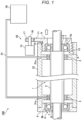
- FIG. 1 is a schematic configuration view of the motor bearing system according to the first embodiment.
- FIG. 2 is a block diagram illustrating an electric configuration of the motor bearing system according to the first embodiment.
- a motor bearing system 100 is mounted to a vehicle and mainly has: a motor 1 (not illustrated in detail in FIG. 1 ) that drives the vehicle; a rotary shaft 2 of the motor 1; a pair of slide bearings 3 that supports the rotary shaft 2; a pair of rolling bearings 4 that is arranged in parallel with the slide bearings 3 on an axis of the rotary shaft 2 and supports the rotary shaft 2; and a housing 12 that accommodates these motor 1, rotary shaft 2, slide bearings 3, and rolling bearings 4.
- the rolling bearings 4 are angular ball bearings, for example, and respectively have: outer rings 5a, 5b; inner rings 6 that are attached to the rotary shaft 2; and plural rolling elements (balls and rollers) 7 that are interposed between the inner ring 6 and respective one of these outer rings 5a, 5b.
- the outer ring 5b of the rolling bearing 4 on a left end side of the rotary shaft 2 is attached to an inner circumferential side of a cylindrical outer ring fixture member 8 while the outer ring 5a of the rolling bearing 4 on a right end side of the rotary shaft 2 is attached to an inner circumferential side of a cylindrical outer ring movable member 9.
- the latter outer ring movable member 9 has a thread groove 10 on an outer circumference at one end and has a fan-shaped gear 11 on the outer circumference at the other end.
- the thread groove 10 of the outer ring movable member 9, to which the outer ring 5a is attached, is threaded onto a thread groove 13 that is formed on an inner circumference at a right end of the housing 12.
- the outer ring fixture member 8, to which the outer ring 5b is attached, is fixed to a left end of the housing 12.
- a switching drive unit 15 that has an unillustrated motor and an unillustrated decelerator therein is provided on an outer circumference on the right end side of such a housing 12.
- This switching drive unit 15 has a drive shaft 16 and a drive gear 17 fixed to this drive shaft 16, and this drive gear 17 meshes with the fan-shaped gear 11 of the outer ring movable member 9.
- the motor bearing system 100 further has a pump 30 that supplies gas (typically air but may be oil gas or a refrigerant) to the slide bearing 3 in order to form a gas layer between the rotary shaft 2 and the slide bearing 3 and thereby achieve gaseous lubrication of the slide bearing 3, that is, to cause the slide bearing 3 to float off the rotary shaft 2 and be operated as a gas-lubricated bearing. More specifically, the pump 30 supplies the gas through a gas supply passage 31 to a clearance (a radial clearance that is defined in a radial direction of the rotary shaft 2) between the rotary shaft 2 and each of the paired slide bearings 3.
- gas typically air but may be oil gas or a refrigerant
- a downstream portion 31a that is connected to the slide bearing 3 is formed in the housing 12 and each of the slide bearings 3.
- each of the slide bearings 3 can float between an outer circumferential surface of the rotary shaft 2 and an inner circumferential surface of the housing 12 that surrounds the rotary shaft 2 and the slide bearings 3.
- the outer ring movable member 9 (including the thread groove 10 and the fan-shaped gear 11), the thread groove 13 of the housing 12, and the switching drive unit 15 (including the drive shaft 16 and the drive gear 17) described above constitute a switching mechanism 20 that switches the bearing, which functions to support the rotary shaft 2, between the rolling bearing 4 and the slide bearing 3.
- the rolling bearing 4 functions as the bearing that supports the rotary shaft 2.
- the radial clearance is generated between the slide bearing 3 and the rotary shaft 2, and the slide bearing 3 does not contact the rotary shaft 2.
- the slide bearing 3 does not function as the bearing that supports the rotary shaft 2.
- the above-described state corresponds to a state (a first state) where the rolling bearing 4 functions as the bearing supporting the rotary shaft 2 and the slide bearing 3 does not function as the bearing supporting the rotary shaft 2.
- the state as described so far that is, the state where the switching drive unit 15 of the switching mechanism 20 is driven corresponds to a state (a second state) where the slide bearing 3 functions as the bearing that supports the rotary shaft 2 and the rolling bearing 4 does not function as the bearing that supports the rotary shaft 2.
- the gear, the thread groove, and the like are used to cause the outer ring 5a to move.
- a predetermined push-out mechanism may be used to cause the outer ring 5a to move.
- the push-out mechanism only needs to apply a push-out force to the outer ring 5a, which is in an urged state by a spring, and an amount of the push-out force is large enough to overcome an urging force of this spring.
- the outer rings 5a, 5b separate from the rolling elements 7.
- the inner rings 6 may separate from the rolling elements 7.
- the motor bearing system 100 has: various sensors 61 to 74; a controller 50 that receives various signals from these various sensors; and the above-described switching drive unit 15, the above-described pump 30, and an inverter 22 that are controlled by a control signal supplied from this controller 50.
- the inverter 22 is connected to the motor 1.
- the controller 50 is implemented by a computer that includes: one or more processors 50a (typically CPUs); and memory 50b, such as ROM and RAM, that stores various programs (including a basic control program such as an OS and an application program activated on the OS to implement a particular function) interpretively executed on the processor 50a and various types of data.
- processors 50a typically CPUs
- memory 50b such as ROM and RAM
- the motor bearing system 100 has: a vehicle speed sensor 61 that detects a speed of the vehicle (a vehicle speed); an acceleration sensor 62 that detects acceleration of the vehicle; an accelerator opening angle sensor 63 that detects an accelerator opening angle corresponding to a depression amount of an accelerator pedal; a brake sensor 64 that detects a depression amount of a brake pedal; a steering angle sensor 65 that detects a rotation angle (a steering angle) of a steering wheel; a motor rotation speed sensor 66 that detects a rotation speed (uniquely a rotational frequency) of the motor 1; a motor torque sensor 67 that detects torque of the motor 1; a pump pressure sensor 68 that detects a pressure of the pump 30; and a bearing load sensor 69 that detects a load (a radial load) applied in the radial direction to each of the slide bearing 3 and the rolling bearing 4.
- the motor rotation speed sensor 66 corresponds to the "detector" in the invention.
- the motor bearing system 100 has: a vehicle camera 70 that captures an image of the surroundings of the vehicle; a radar 71 (for example, a millimeter-wave radar) that measures a location and a speed of a target object (another vehicle, a pedestrian, an obstacle, or the like) that exists around the vehicle; a communicator 72 that makes inter-vehicle communication and road-to-vehicle communication; a positioning system 73 that includes a GPS system, a gyroscopic system, or the like to detect a location of the vehicle; and a navigation system 74 that stores map data.
- a laser radar, an ultrasonic sensor, or the like may be used.
- FIG. 3 a horizontal axis represents the motor rotation speed, and a vertical axis represents shaft friction torque.
- the bearing that functions to support the rotary shaft of the motor is switched between the rolling bearing and the slide bearing, for which fluid lubrication with lubricating oil is used. More specifically, in the comparative example, when the motor rotation speed is in a range R11 (hereinafter appropriately referred to as a "low-speed range", the rolling bearing is applied as the bearing that functions to support the rotary shaft 2. Meanwhile, when the motor rotation speed is in a higher range R12 than the low-speed range R11, the slide bearing is applied as the bearing that functions to support the rotary shaft 2.
- This control corresponds to the technique disclosed in Patent Literature 1.
- a graph G11 indicates the shaft friction torque that is generated to the rolling bearing, that is, boundary lubrication friction due to direct contact
- a graph G12 indicates the shaft friction torque that is generated to the slide bearing, for which the fluid lubrication with the lubricating oil is used, that is, fluid lubrication friction of the lubricating oil.
- the shaft friction torque that is generated in the motor bearing control according to the comparative example is a sum of the shaft friction torque indicated by the graph G11 and the shaft friction torque indicated by the graph G12, that is, is indicated by a graph G21.
- the shaft friction torque is significantly increased as the motor rotation speed is increased. This is because of an increase in the friction due to deformation of the rolling element in the rolling bearing, as indicated by a graph G13.
- the bearing that functions to support the rotary shaft 2 of the motor 1 is switched between the rolling bearing 4 and the slide bearing 3 that is operable as the gas-lubricated bearing with the gas supplied from the pump 30.
- the wedge effect and the restriction effect are hardly exerted.
- an electric efficiency improvement allowance that can be obtained by applying the slide bearing 3 to be operated as the gas-lubricated bearing becomes smaller than an electric efficiency reduction allowance that is obtained by actuating the pump 30 to realize this gas-lubricated bearing (that is, electricity consumption by the pump 30 is significantly increased).
- the controller 50 controls the switching drive unit 15 of the switching mechanism 20 so as to apply the rolling bearing 4 as the bearing that functions to support the rotary shaft 2.
- the controller 50 controls the switching drive unit 15 so as not to cause the slide bearing 3 to function but to cause only the rolling bearing 4 to function.
- the controller 50 controls the switching drive unit 15 to apply the slide bearing 3 as the bearing that functions to support the rotary shaft 2.
- the controller 50 controls the switching drive unit 15 to cause only the slide bearing 3 to function while actuating the pump 30.
- the controller 50 stops the pump 30 and controls the switching drive unit 15 to cause only the slide bearing 3 to function.
- a graph G14 indicates the shaft friction torque that is generated to the slide bearing 3 operated as the gas-lubricated bearing, that is, the gaseous lubrication friction.
- the shaft friction torque that is generated in the motor bearing control according to the above first embodiment is a sum of the shaft friction torque indicated by the graph G11 and the shaft friction torque indicated by the graph G14, that is, is indicated by a graph G22.
- the shaft friction torque according to the first embodiment which is indicated by such a graph G22
- the comparative example which is indicated by the graph G21
- FIG. 4 includes time charts illustrating the motor bearing control according to the first embodiment.
- a horizontal axis represents time
- vertical axes sequentially represent, from top, the motor rotation speed, a signal (hereinafter referred to as a "bearing switching signal") that is supplied to the switching drive unit 15 of the switching mechanism 20, and an on/off signal of the pump 30.
- the controller 50 sets the switching mechanism 20 to cause only the rolling bearing 4 to function (in this case, the bearing switching signal supplied to the switching drive unit 15 is off).
- the controller 50 turns on the bearing switching signal supplied to the switching drive unit 15 and thereby causes only the slide bearing 3 to function, that is, switches the bearing that functions to support the rotary shaft 2 of the motor 1 from the rolling bearing 4 to the slide bearing 3.
- the controller 50 turns on the pump 30 to form the gas layer between the rotary shaft 2 and the slide bearing 3 by the gas from the pump 30, and operates the slide bearing 3 as the gas-lubricated bearing.
- the pump 30 may be turned on (the pump signal may be turned on) before the bearing switching signal is turned on.
- the controller 50 turns off the pump 30 while turning on the bearing switching signal supplied to the switching drive unit 15. This is because, in the high-speed range R14, the sliding speed is extremely high, the significantly high wedge effect and restriction effect can be exerted, and the gas-lubricated bearing can thereby be realized without actuating the pump 30.
- FIG. 5 is a graph for a basic control method of the pump driving force according to the first embodiment.
- a horizontal axis represents the motor rotation speed
- a vertical axis represents the pump driving force.
- the controller 50 actuates the pump 30 to generate the pump driving force only when the motor rotation speed is equal to or higher than the first speed V1 and lower than the second speed V2 (that is, in the middle-speed range R13). At this time, the controller 50 reduces the pump driving force as the motor rotation speed is increased (see a solid line in FIG. 5 ).
- the control is not limited to such an example that the pump driving force is reduced as the motor rotation speed is increased (the solid line in FIG. 5 ).
- the pump driving force may be constant regardless of the motor rotation speed(the broken line in FIG.5 ).
- a horizontal axis represents radial acceleration that is exerted on the rotary shaft 2 of the motor 1
- a vertical axis represents a correction factor that is used to correct the pump driving force set according to the motor rotation speed.
- This radial acceleration is also exerted on the slide bearing 3 and the rolling bearing 4.
- the radial acceleration uniquely corresponds to the radial load.
- the radial load may directly be used instead of the radial acceleration.
- the radial acceleration may be converted to the radial load from vehicle weight or the like (hereinafter the same).
- the radial acceleration is increased during travel on a rough road, during travel over a bump, when the steering angle is large, when power hop occurs, or the like, for example.
- the pump driving force is increased as the radial acceleration is increased.
- the controller 50 makes a correction to increase the pump driving force, which is set according to the motor rotation speed as illustrated in FIG. 5 , by using the correction factor set such that a value thereof is increased as the radial acceleration is increased. In this way, when the radial acceleration is high, it is possible to avoid a contact risk of the slide bearing 3 with the rotary shaft 2 and thus to ensure safety and reliability.
- a horizontal axis represents the radial acceleration that is exerted on the rotary shaft 2 of the motor 1
- a vertical axis represents the pump driving force that is applied according to the radial acceleration in the high-speed range R14.
- the controller 50 basically stops the pump 30, that is, does not cause generation of the pump driving force in the high-speed range R14 (that is, when the motor rotation speed is equal to or higher than the second speed V2).
- the controller 50 continues to actuate the pump 30, and increases the pump driving force as the radial acceleration is increased as illustrated in FIG. 7 . Also, in this way, when the radial acceleration is high, it is possible to avoid the contact risk of the slide bearing 3 with the rotary shaft 2 and thus to ensure the safety and the reliability.
- the controller 50 predicts the radial acceleration that is used to control the pump driving force as described above. This is because, even when the pump driving force is controlled on the basis of the currently generated radial acceleration (for example, can be calculated from the radial load detected by the bearing load sensor 69), the safety and the reliability cannot adequately be ensured. In other words, this is because the precise pump driving force control cannot be executed in time when the currently generated radial acceleration is used. In particular, this is because the radial acceleration tends to be increased rapidly rather than being gradually increased. Thus, in the first embodiment, the controller 50 predicts the radial acceleration that is generated in the future, and executes the control of the pump driving force on the basis of this radial acceleration.
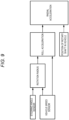
- FIG. 8 is a flowchart illustrating the motor bearing control according to the first embodiment. This flow is repeatedly executed by the controller 50 in a predetermined cycle.
- the processor 50a in the controller 50 reads the program stored in the memory 50b to execute the program, and thereby realizes the motor bearing control for this flow.
- step S101 the controller 50 obtains the various signals from the various sensors 61 to 74 illustrated in FIG. 2 .
- step S102 the controller 50 determines whether the motor 1 is stopped. For example, the controller 50 determines whether the motor 1 is stopped on the basis of the motor rotation speed that corresponds to the signal supplied from the motor rotation speed sensor 66. As a result, if the controller 50 determines that the motor 1 is stopped (step S102: Yes), the processing proceeds to step S103. On the other hand, if not determining that the motor 1 is stopped (step S102: No), the controller 50 terminates the motor bearing control.
- step S103 the controller 50 sets the switching drive unit 15 of the switching mechanism 20 so as to apply the rolling bearing 4 as the bearing that functions to support the rotary shaft 2 of the motor 1.
- the controller 50 controls the switching drive unit 15 so as to switch the bearing that functions to support the rotary shaft 2 from the slide bearing 3 to the rolling bearing 4.
- step S104 the controller 50 determines whether a vehicle start request is present. For example, the controller 50 determines whether the start request is present on the basis of the accelerator opening angle that corresponds to the signal supplied from the accelerator opening angle sensor 63. As a result, if the controller 50 determines that the start request is present (step S104: Yes), the processing proceeds to step S105, and the motor 1 is started. On the other hand, if not determining that the start request is present (step S104: No), the controller 50 terminates the motor bearing control.
- step S106 the controller 50 determines whether the motor rotation speed detected by the motor rotation speed sensor 66 is equal to or higher than the first speed V1, that is, whether the motor rotation speed is in the middle-speed range R13. As a result, if the controller 50 determines that the motor rotation speed is equal to or higher than the first speed V1 (step S106: Yes), the processing proceeds to step S107. On the other hand, if the controller 50 does not determine that the motor rotation speed is equal to or higher than the first speed V1 (step S106: No), the processing returns to step S106.
- step S107 the controller 50 predicts the radial acceleration that is exerted on the rotary shaft 2 of the motor 1.
- a description will herein be made on a specific example of a method for predicting the radial acceleration that is executed in step S107 with reference to FIG. 9 to FIG. 11 .
- FIG. 9 is a diagram of a first example of the method for predicting the radial acceleration.
- the first example is an example in which the radial acceleration is predicted on the basis of the steering angle.
- the controller 50 first calculates a rotation radius (a turning radius) of the vehicle on the basis of the steering angle detected by the steering angle sensor 65 and the vehicle speed detected by the vehicle speed sensor 61. Then, the controller 50 calculates roll acceleration generated to the vehicle on the basis of this rotation radius and the vehicle speed.
- the controller 50 then predicts the radial acceleration to be exerted on the rotary shaft 2 in the future on the basis of this roll acceleration and a position of the rotary shaft 2 in the vehicle (is a fixed position and stored in a memory 50b or the like; positions of the slide bearing 3 and the rolling bearing 4 may be used). Basically, the controller 50 predicts the radial acceleration with a higher value as the roll acceleration is increased.
- FIG. 10 is a diagram of a second example of the method for predicting the radial acceleration.
- the second example is an example in which the radial acceleration is predicted on the basis of the bump (in detail, power hop of the vehicle caused by the bump) on a road surface on which the vehicle travels. As illustrated in FIG.
- the controller 50 first predicts a bump height on a course (in particular, a height of the descending bump) on the basis of the image of the surroundings of the vehicle captured by the vehicle camera 70, the location and the speed of the target object that exists around the vehicle measured by the radar 71, the map data stored in the navigation system 74, the signal obtained by the communicator 72 through the inter-vehicle communication and the road-to-vehicle communication, and the like.
- the controller 50 calculates an idling time of a tire by the bump on the basis of this bump height, the accelerator opening angle detected by the accelerator opening angle sensor 63, and the vehicle speed detected by the vehicle speed sensor 61, and calculates a peripheral rotation speed of the tire on the basis of this idling time.
- the controller 50 calculates a power hop load of the vehicle generated by the bump on the basis of this peripheral rotation speed of the tire and the vehicle speed, and predicts the radial acceleration to be exerted on the rotary shaft 2 in the future on the basis of this power hop load.
- the controller 50 calculates the longer idling time, the higher peripheral rotation speed, and the larger power hop load as the bump height is increased. As a result, the controller 50 predicts the radial acceleration with the high value.
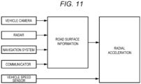
- FIG. 11 is a diagram of a third example of the method for predicting the radial acceleration.
- the third example is an example in which the radial acceleration is predicted on the basis of a condition of the road surface on which the vehicle travels.
- the controller 50 first obtains road surface information indicating a condition of the road surface on which the vehicle travels on the basis of the image of the surroundings of the vehicle captured by the vehicle camera 70, the location and the speed of the target object that exists around the vehicle measured by the radar 71, the map data stored in the navigation system 74, the signal obtained by the communicator 72 through the inter-vehicle communication or the road-to-vehicle communication, or the like.
- the controller 50 obtains, as the road surface information, information on a curve, the rough road, the bump, and the like that exist in the course.
- the controller 50 can acknowledge vibration of the own vehicle caused by the rough road through the inter-vehicle communication by the communicator 72.
- the controller 50 predicts the radial acceleration to be exerted on the rotary shaft 2 in the future. For example, in the case where the road surface condition is that of the rough road, the controller 50 predicts the radial acceleration with a high value that corresponds to a degree of roughness of the road.
- the methods for predicting the radial acceleration according to the first to third examples described above may be combined and executed.
- step S108 the controller 50 determines whether this radial acceleration is lower than a predetermined value. As a result, if the controller 50 determines that the radial acceleration is lower than the predetermined value (step S108: Yes), the processing proceeds to step S109. On the other hand, if the controller 50 does not determine that the radial acceleration is lower than the predetermined value (step S108: No), the processing returns to step S106. In the latter case, the controller 50 repeats the processing in steps S106 to S108 until the motor rotation speed becomes equal to or higher than the first speed V1 and the radial acceleration becomes lower than the predetermined value.
- step S109 the controller 50 calculates the pump driving force to be applied in order to supply the gas from the pump 30 and operate the slide bearing 3 as the gas-lubricated bearing. More specifically, the controller 50 calculates the pump driving force that corresponds to the current motor rotation speed ( FIG. 5 ), corrects this pump driving force with the correction factor corresponding to the radial acceleration predicted in step S106 ( FIG. 6 ), and thereby calculates the pump driving force to be applied. Then, in step S110, the controller 50 controls the pump 30 by the pump driving force calculated in step S109. Next, in step S111, the controller 50 controls the switching drive unit 15 of the switching mechanism 20 so as to switch the bearing that functions to support the rotary shaft 2 from the rolling bearing 4 to the slide bearing 3.
- step S112 the controller 50 determines whether the motor rotation speed detected by the motor rotation speed sensor 66 is equal to or higher than the second speed V2, that is, whether the motor rotation speed is in the high-speed range R14. As a result, if the controller 50 determines that the motor rotation speed is equal to or higher than the second speed V2 (step S112: Yes), the processing proceeds to step S113. On the other hand, if the controller 50 does not determine that the motor rotation speed is equal to or higher than the second speed V2 (step S112: No), the processing returns to step S112.
- step S113 the controller 50 predicts the radial acceleration that is exerted on the rotary shaft 2 of the motor 1 again. Similar to step S107 described above, the controller 50 predicts the radial acceleration (see FIG. 9 to FIG. 11 ). Then, in step S114, the controller 50 determines whether this radial acceleration, which is predicted in step S113, is lower than a predetermined value.
- the predetermined value that is used in this step S114 may be the same as or different from the predetermined value that is used in the determination in step S108. As a result of step S114, if the controller 50 determines that the radial acceleration is lower than the predetermined value (step S114: Yes), the processing proceeds to step S115.
- the gas-lubricated bearing can be realized without actuating the pump 30.
- the controller 50 stops the pump 30 (step S115) . Then, the controller 50 terminates the motor bearing control.
- step S116 the controller 50 calculates the pump driving force that is applied when the radial acceleration is high in the high-speed range R14. In this case, the controller 50 calculates the pump driving force that corresponds to the radial acceleration predicted in step S113 ( FIG. 7 ). Then, in step S117, the controller 50 continues to drive the pump 30 by using the pump driving force calculated in step S116. Thereafter, the controller 50 returns to step S112.
- the pump 30 is stopped in the step S115 as described above.
- a condition that a straight road continues on the travel road of the vehicle for example, such a condition is satisfied during travel on a controlled-access highway
- a condition that a flat road surface continues on the travel road of the vehicle may be used.
- the controller 50 can determine any of such conditions from the image of the surroundings of the vehicle captured by the vehicle camera 70, the map data stored in the navigation system 74, or the like, for example.
- the controller 50 (1) sets the switching mechanism 20 such that the rolling bearing 4 does not function as the bearing supporting the rotary shaft 2 but the slide bearing 3 functions as the bearing supporting the rotary shaft 2, and controls the pump 30 to operate the slide bearing 3 as the gas-lubricated bearing when the motor rotation speed is equal to or higher than the first speed V1 and is lower than the second speed V2, (2) stops the pump 30 when the motor rotation speed is equal to or higher than the second speed V2, and (3) further does not stop the pump 30 in the case where the radial acceleration exerted on the rotary shaft 2 is equal to or higher than the predetermined value even when the motor rotation speed is equal to or higher than the second speed V2.
- the controller 50 applies the slide bearing 3 as the bearing that functions to support the rotary shaft 2.
- the electric efficiency improvement allowance which is obtained by applying the slide bearing 3 as the gas-lubricated bearing, becomes larger than the electric efficiency reduction allowance, which is obtained by actuating the pump to realize the gas-lubricated bearing.
- the gas-lubricated bearing when the motor rotation speed is equal to or higher than the second speed V2, that is, in the high-speed range R14 where the sliding speed is extremely high, the gas-lubricated bearing can be realized even without applying the static pressure by the pump 30. Accordingly, the controller 50 applies the slide bearing 3 as the bearing that functions to support the rotary shaft 2 while stopping the pump 30. In this way, it is possible to maximize the electric efficiency improvement effect, which is exerted by applying the gas-lubricated bearing.
- the pump 30 in the case where the radial acceleration is equal to or higher than the predetermined value, the pump 30 is not stopped, that is, the actuation of the pump 30 continues even when the motor rotation speed is equal to or higher than the second speed V2. Accordingly, when the radial acceleration is high, it is possible to avoid the contact risk of the slide bearing 3 with the rotary shaft 2 and thus to ensure the safety and the reliability.
- the electric efficiency reduction allowance at the time when the actuation of the pump 30 is continued is smaller than the electric efficiency reduction allowance obtained due to the increased friction caused by the contact between the slide bearing 3 and the rotary shaft 2, which possibly occurs when the pump 30 is stopped. Thus, it is possible to suppress the electric efficiency reduction as much as possible.
- the controller 50 increases the pump driving force as the radial acceleration is increased.
- the controller 50 increases the pump driving force as the radial acceleration is increased.
- the controller 50 predicts the radial acceleration on the basis of the steering angle, the bump on the road surface, and the condition of the road surface. By using the future radial acceleration that is predicted just as described, it is possible to effectively avoid the contact of the slide bearing 3 with the rotary shaft 2 caused by the increase in the radial acceleration.
- the controller 50 when the motor rotation speed is equal to or higher than the first speed V1 and is lower than the second speed V2 (in the middle-speed range R13), the controller 50 reduces the pump driving force as the motor rotation speed is increased. In this way, it is possible to cut down the electricity consumption by the pump 30 in the middle-speed range R13 and thus to improve the electric efficiency.
- the pump 30 is stopped when the motor rotation speed is lower than the first speed V1.
- the pump 30 may be actuated to a certain extent.
- the controller 50 reduces a driving force of the pump 30 to be smaller than that at the time when the motor rotation speed is equal to or higher than the first speed V1 and is lower than the second speed V2.
- the pump 30 is stopped when the motor rotation speed is equal to or higher than the second speed V2 and the radial acceleration is lower than the predetermined value (see FIGS. 4 and 8 ).
- the pump 30 may be actuated to a certain extent.
- the controller 50 reduces the driving force of the pump 30 to be smaller than that at the time when the motor rotation speed is equal to or higher than the first speed V1 and is lower than the second speed V2 or that at the time when the motor rotation speed is equal to or higher than the second speed V2 and the radial acceleration is equal to or higher than the predetermined value.
- the motor bearing control is executed on the basis of the motor rotation speed.
- the motor bearing control may be executed on the basis of the motor rotational frequency. This is because the motor rotational frequency uniquely corresponds to the motor rotation speed.
- FIG. 12 is a schematic configuration view of a motor bearing system according to the modified example of the first embodiment.
- the switching mechanism 20a is driven not by the switching drive unit 15 as in the above-described embodiment but by the pump 30. More specifically, in the switching mechanism 20a, the drive shaft 16 of the drive gear 17 that meshes with the fan-shaped gear 11 of the outer ring movable member 9 is not driven by the switching drive unit 15 as in the above-described embodiment but by the pump 30.
- the drive shaft 16 of the switching mechanism 20a and a rotary shaft 32 of the pump 30 are connected via a predetermined transmission member 18 such as a belt, a chain, or a gear.
- a predetermined transmission member 18 such as a belt, a chain, or a gear.
- rotation of the rotary shaft 32 of the pump 30 is transmitted to the drive shaft 16 of the switching mechanism 20a.
- the controller 50 indirectly controls the switching mechanism 20a via the pump 30 instead of directly controlling the switching mechanism 20a.
- the second embodiment differs from the first embodiment in a point that the pump driving force is controlled on the basis of the vehicle speed. More specifically, in the second embodiment, in the case where the radial acceleration exerted on the rotary shaft 2 is equal to or higher than the predetermined value while the pump 30 is actuated to operate the slide bearing 3 as the gas-lubricated bearing, the controller 50 increases the pump driving force to be larger than that at the time when the radial acceleration is lower than the predetermined value, and changes such a predetermined value according to the vehicle speed.
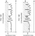
- FIGS. 13A and 13B are graphs for the motor bearing control according to the second embodiment. More specifically, FIG. 13A is the graph of the motor bearing control at the low vehicle speed, and FIG. 13B is the graph of the motor bearing control at the high vehicle speed.
- a horizontal axis represents the time, and a vertical axis represents the radial acceleration exerted on the rotary shaft 2.
- the controller 50 increases the pump driving force to be larger than that at the time when the radial acceleration is lower than the predetermined value, and changes this predetermined value according to the vehicle speed. More specifically, as illustrated in FIGS. 13A and 13B , the controller 50 reduces a predetermines value A12 used at the high vehicle speed to be lower than a predetermined value A11 used at the low vehicle speed. In other words, the controller 50 reduces the predetermined value, which is used to increase the pump driving force according to the radial acceleration, as the vehicle speed is increased.
- a radial acceleration range where the control for increasing the pump driving force is executed is larger at the high vehicle speed than at the low vehicle speed (a range R22 > a range R21). This is because, even at the same radial acceleration, it is more difficult to secure the gas layer between the slide bearing 3 and the rotary shaft 2 at the high vehicle speed than at the low vehicle speed, and thus the possibility that the slide bearing 3 contacts the rotary shaft 2 is increased.
- the predetermined value which is used to increase the pump driving force according to the radial acceleration, is changed according to the vehicle speed.
- the bearing that functions to support the rotary shaft 2 of the motor 1 is switched between the rolling bearing 4 and the slide bearing 3 that is operable as the gas-lubricated bearing by the gas supplied from the pump 30.
- the third embodiment differs from the first embodiment in a point that, instead of using the two bearings of the rolling bearing 4 and the slide bearing 3, only one rolling bearing is used to supply the gas from the pump 30 to this rolling bearing, and the rolling bearing is thereby operated as the gas-lubricated bearing that achieves the gaseous lubrication.
- the switching mechanisms 20, 20a as described in the first embodiment are not provided.
- FIG. 14 is a schematic configuration view of a motor bearing system according to the third embodiment.
- a motor bearing system 101 according to the third embodiment has: the motor 1 that includes a rotor 1a and a stator 1b; the rotary shaft 2 of the motor 1; a pair of rolling bearings 24 that supports the rotary shaft 2; and the housing 12 that accommodates these motor 1, rotary shaft 2, and rolling bearings 24.
- Each of the rolling bearings 24 has: an outer ring 25 that is fixed to the housing 12; an inner ring 26 that is attached to the rotary shaft 2 of the motor; plural rolling elements (balls and rollers) 27 that are interposed between these outer ring 25 and inner ring 26; and a holding section 28 that holds the plural rolling elements 27.
- the bearing load sensor 69 is provided to detect the load (the radial load) that is radially applied to the rolling bearing 24.
- the motor bearing system 101 further has the pump 30 that supplies the gas (typically the air but may be the oil gas or the refrigerant) to the rolling bearing 24 in order to form the gas layer between the rotary shaft 2 and the rolling bearing 24 and thereby achieve the gaseous lubrication of the rolling bearing 24, that is, to cause the rolling bearing 24 to operate as the gas-lubricated bearing. More specifically, the pump 30 supplies the gas through the gas supply passage 31 to a portion (the radial clearance that is defined in the radial direction of the rotary shaft 2) between the inner ring 26 in each of the paired rolling bearings 24 and the holding section 28 holding the rolling element 27. In this gas supply passage 31, the downstream portion 31a thereof is formed in the housing 12, the outer ring 25 of the rolling bearing 24, and the holding section 28.
- the gas typically the air but may be the oil gas or the refrigerant
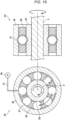
- FIG. 15 illustrates a state of the rolling bearing 24 at the time when the pump 30 is not actuated in the motor bearing system 101.
- FIG. 15 illustrates a transverse cross section of the rotary shaft 2 and the rolling bearing 24 on a left side, and illustrates a vertical cross section of the rotary shaft 2 and the rolling bearing 24 that is orthogonal to this transverse cross section on a right side.
- the rolling element 27 of the rolling bearing 24 is in contact with the outer ring 25 and the inner ring 26, and the rolling bearing 24 literally functions as the rolling bearing.
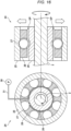
- FIG. 16 illustrates the state of the rolling bearing 24 at the time when the pump 30 is actuated in the motor bearing system 101.
- FIG. 16 illustrates a transverse cross section of the rotary shaft 2 and the rolling bearing 24 on a left side, and illustrates a vertical cross section of the rotary shaft 2 and the rolling bearing 24 that is orthogonal to this transverse cross section on a right side.
- the gas layer is formed in a clearance SP between the inner ring 26 and the holding section 28, which holds the rolling element 27, by the gas supplied from the pump 30, and the holding section 28 and the rolling element 27 float from the inner ring 26.
- the holding section 28 is fixed to the outer ring 25 by a locking member (a claw or the like), which is not illustrated, so as not to rotate.
- a locking member a claw or the like
- the rolling bearing 24 no longer functions as the rolling bearing. Instead, the rolling bearing 24 functions as the gas-lubricated bearing that achieves the gaseous lubrication by the gas supplied from the pump 30.
- the gas-lubricated bearing is realized (thus the pump 30 is stopped) even when the static pressure is not applied by the pump 30.
- the single rolling bearing 24 is selectively operated as the rolling bearing or the gas-lubricated bearing.
- the similar motor bearing control to that in the first and second embodiments can be executed with the simple configuration.
Landscapes
- Engineering & Computer Science (AREA)
- General Engineering & Computer Science (AREA)
- Mechanical Engineering (AREA)
- Power Engineering (AREA)
- Microelectronics & Electronic Packaging (AREA)
- Chemical & Material Sciences (AREA)
- Combustion & Propulsion (AREA)
- Transportation (AREA)
- Rolling Contact Bearings (AREA)
- Magnetic Bearings And Hydrostatic Bearings (AREA)
Abstract
Description
- The present invention relates to a motor bearing system.
- A rolling bearing and a slide bearing have been used as bearings, each of which supports a rotary shaft of a power source (an engine or a motor) or the like of a vehicle, for example. While the rolling bearing has low friction in a low-speed range, the slide bearing has high friction in the low-speed range. Meanwhile, while the rolling bearing has a finite life due to rolling contact fatigue, the slide bearing has an infinite life under an appropriate lubrication condition.
- Here, the following technique has been proposed. A system having both of the rolling bearing and the slide bearing is configured to switch the applied bearing according to characteristics of each of the bearings as described above. For example, a system using the rolling bearing and the slide bearing as the bearing that supports a crankshaft or a camshaft of the engine is disclosed in
Patent Literature 1. In such a system, only the rolling bearing functions at a start at a low rotational frequency, and only the slide bearing functions after this start. - [Patent Literature 1]
JP2009-19728A - As described above, in the engine, application of the slide bearing is effective in a high-speed range. Fluid lubrication with lubricating oil is generally used for this slide bearing. By the way, the motor that is operated at the higher speed than the engine has such a problem that, when such a slide bearing is applied in the high-speed range of the motor, fluid friction and resistance of the lubricating oil are increased, which worsens electric efficiency of the motor.
- In order to solve such a problem, the present inventor has considered to apply a gas-lubricated bearing (for example, an air bearing), for which lubrication (gaseous lubrication) with gas having lower viscosity than the lubricating oil is used, as the slide bearing. In order to realize such a gas-lubricated bearing, a gas layer has to be reliably formed between the bearing and the rotary shaft in order to prevent contact therebetween. It is considered that a so-called wedge effect and a so-called restriction effect are preferably used to form this gas layer. However, the wedge effect and the restriction effect can only basically be exerted in the high-speed range. Thus, in a method using these effects, the bearing and the rotary shaft possibly contact each other in the low-speed range.
- In view of the above, in order to reliably form the gas layer for the gas-lubricated bearing in the low-speed range, the present inventor has considered to apply a static pressure to the bearing by a pump. However, since electricity consumption by the pump worsens the electric efficiency, it is desired to minimize actuation of the pump. Here, the gas layer is formed according to a combination of the static pressure, which is applied by the pump, and a pressure generated by the wedge effect and the restriction effect described above. These effects are determined by the viscosity of the gas, a sliding speed, and the pressure. In addition, degrees of occurrence of these effects can be comprehended from the motor rotation speed (uniquely, the rotational frequency; hereinafter the same).
- From an experiment performed by the present inventor, it is found that, since the wedge effect and the restriction effect cannot be exerted in the low-speed range of the motor, an electric efficiency improvement allowance obtained by applying the gas-lubricated bearing is smaller than an electric efficiency reduction allowance obtained by actuating the pump to realize the gas-lubricated bearing, and thus the gas-lubricated bearing should not be applied. Meanwhile, it is also found that, in the high-speed range of the motor where the sliding speed becomes extremely high, the significant wedge effect and restriction effect can be exerted, and thus the gas-lubricated bearing can be realized without applying the static pressure by the pump. From the findings described so far, the present inventor has considered to actuate the pump in a range (referred to as a middle-speed range) between the low-speed range and the high-speed range while stopping the pump or reducing a driving force of the pump in the high-speed range in order to realize the gas-lubricated bearing.
- In addition, from a further experiment performed by the present inventor, it has been found that, when a radial load applied to the rotary shaft of the motor is large, it is difficult to secure the gas layer between the bearing and the rotary shaft, and thus the bearing possibly contacts the rotary shaft. For example, the radial load is increased during travel on a rough road, during travel over a bump, when a steering angle is large, or the like. Based on such findings, the present inventor has conceived of executing control for the pump, which is used to realize the gas-lubricated bearing, in consideration of the radial load applied to the rotary shaft of the motor, and has completed the invention.
- The invention has been made on the basis of the findings as described so far and therefore has a purpose of precisely executing control for a pump on the basis of a radial load applied to a rotary shaft of a motor in a motor bearing system that has a bearing operable as a gas-lubricated bearing by gas supplied from the pump.
- In order to achieve the above purpose, the invention is a motor bearing system and has: a rolling bearing that supports a rotary shaft of a motor; a slide bearing that is arranged in parallel with the rolling bearing on an axis of the rotary shaft to support the rotary shaft, the slide bearing being operable as a gas-lubricated bearing that achieves gaseous lubrication with gas supplied to the slide bearing; a pump that supplies the gas to the slide bearing; a detector that detects a rotation speed of the motor; and a controller that controls the pump on the basis of the rotation speed detected by the detector. The controller: controls the pump such that, when the rotation speed is equal to or higher than a first speed and is lower than a second speed that is higher than the first speed, the rolling bearing does not function as a bearing that supports the rotary shaft, but the slide bearing functions as the bearing that supports the rotary shaft, and the slide bearing functions as the gas-lubricated bearing; and controls the pump to stop the pump or reduce a driving force of the pump to be smaller than that at the time when the rotation speed is equal to or higher than the first speed and lower than the second speed in the case where the rotation speed is equal to or higher than the second speed. The controller further controls the pump such that, in the case where the rotation speed is equal to or higher than the second speed and a radial load exerted on the rotary shaft is equal to or larger than a predetermined value, the pump is not stopped, and the driving force of the pump is increased to be larger than that at the time when the radial load is smaller than the predetermined value.
- In the invention that is configured as described above, the controller comprehends magnitudes of exertion of a wedge effect and a restriction effect from the motor rotation speed and executes the control related to the bearing. The motor rotation speed precisely reflects the magnitudes of the exertion of the wedge effect and the restriction effect. Thus, according to the invention, this control can be executed accurately with the simple configuration.
- More specifically, in the invention, when the motor rotation speed is equal to or higher than the first speed and is lower than the second speed, the wedge effect and the restriction effect are exerted to a certain extent. For this reason, the electricity consumption of the pump that is required to operate the slide bearing as the gas-lubricated bearing is relatively small. Thus, the controller applies the slide bearing as the bearing that functions to support the rotary shaft. In this case, an electric efficiency improvement allowance, which is obtained by applying the slide bearing as the gas-lubricated bearing, becomes larger than an electric efficiency reduction allowance, which is obtained by actuating the pump to realize the gas-lubricated bearing. Thus, it is possible to ensure an electric efficiency improvement effect, which is exerted by applying the gas-lubricated bearing.
- In addition, in the invention, when the motor rotation speed is equal to or higher than the second speed, the sliding speed is extremely high, and the gas-lubricated bearing can be realized without applying the static pressure by the pump. Thus, the controller applies the slide bearing as the bearing that functions to support the rotary shaft while stopping the pump or reducing the driving force of the pump. In this way, it is possible to maximize the electric efficiency improvement effect, which is exerted by applying the gas-lubricated bearing.
- Furthermore, in the invention, even in the case where the motor rotation speed is equal to or higher than the second speed, the pump is not stopped, and the pump driving force is increased to be larger than that at the time when the radial load (uniquely corresponding to the radial acceleration) applied to the rotary shaft is smaller than the predetermined value when the radial load is equal to or larger than the predetermined value. Thus, when the radial load is large, it is possible to avoid a contact risk of the slide bearing with the rotary shaft and thus to ensure safety and reliability. An electric efficiency reduction allowance at the time of executing such control for the pump driving force is smaller than the electric efficiency reduction allowance obtained due to the contact between the slide bearing and the rotary shaft, which possibly occurs when the control for the pump driving force is not executed. Thus, it is possible to suppress an electric efficiency reduction as much as possible. Preferably, the motor bearing system comprises a switching mechanism capable of setting one of a first state and a second state, in the first state, the rolling bearing functioning as a bearing that supports the rotary shaft and the slide bearing not functioning as the bearing that supports the rotary shaft, and in the second state, the slide bearing functioning as the bearing that supports the rotary shaft and the rolling bearing not functioning as the bearing that supports the rotary shaft, and the controller is configured to controls the pump and the switching mechanism on the basis of the rotation speed that is detected by the detector.
Further, preferably, the controller may be configured to set the switching mechanism in the first state when the rotation speed is lower than the first speed; and to set the switching mechanism in the second state when the rotation speed is equal to or higher than the first speed. - From another perspective, in order to achieve the above purpose, the invention is a motor bearing system and has: a bearing that includes plural rolling elements and supports a rotary shaft of a motor, the bearing being operated as a rolling bearing or being operated as a gas-lubricated bearing that achieves gaseous lubrication with gas supplied to the bearing (that is, the bearing is configured such that it can be operated selectively as a rolling bearing in a first state and as a gas-lubricated bearing in a second state) ; a pump that supplies the gas to the bearing; a detector that detects a rotation speed of the motor; and a controller that controls the pump on the basis of the rotation speed detected by the detector. The controller: controls the pump such that, when the rotation speed is equal to or higher than a first speed and is lower than a second speed that is higher than the first speed, the bearing is operated as the gas-lubricated bearing; and controls the pump such that, in the case where the rotation speed is equal to or higher than the second speed, the pump is stopped or a driving force of the pump is reduced to be smaller than that at the time when the rotation speed is equal to or higher than the first speed and lower than the second speed. The controller further controls the pump such that, in the case where the rotation speed is equal to or higher than the second speed and a radial load exerted on the rotary shaft is equal to or larger than a predetermined value, the pump is not stopped, and the driving force of the pump is increased to be larger than that at the time when the radial load is smaller than the predetermined value.
- Also, by the invention that is configured as described above, it is possible to precisely execute the control for the pump on the basis of the radial load applied to the rotary shaft of the motor. In particular, in the invention described above, the single bearing is selectively operated as the rolling bearing or the gas-lubricated bearing. Thus, it is possible to execute the control for the pump with the simple configuration.
- In the invention, preferably, the controller increases the driving force of the pump as the radial load is increased.
- According to the invention that is configured as described above, when the radial load is large, it is possible to effectively avoid the contact risk of the bearing with the rotary shaft.
- In particular, the controller may be configured to increase the driving force of the pump as the radial load is increased in the case where the rotation speed is equal to or higher than the second speed and/or in the case when the rotation speed is equal to or higher than a first speed and lower than the second speed.
- In the invention, preferably, the controller makes a correction to increase the pump driving force set according to the rotation speed, by using a correction factor set such that a value thereof is increased as the radial acceleration is increased.
- In the invention, preferably, the controller is configured to predict the radial load that is applied to the rotary shaft and to control the motor bearing system on the basis of the predicted radial load.
- Thereby, it is taken into account that the radial load may change more quickly than it is possible to switch between bearing operation states, such that using a predicted values rather than a measured value for the radial load will reduce the risk of a contact of the bearing with the rotary shaft.
- In the invention, preferably, the controller predicts the radial load on the basis of a steering angle of a vehicle mounted with the motor bearing system.
- According to the invention that is configured as described above, the future radial load that is predicted on the basis of the steering angle is used. In this way, it is possible to effectively avoid the contact of the bearing with the rotary shaft, which is caused by an increase in the radial load.
- In the invention, preferably, the controller predicts the radial load on the basis of a bump on a road surface on which a vehicle mounted with the motor bearing system travels.
- According to the invention that is configured as described above, the future radial load that is predicted on the basis of the bump on the road surface is used. In this way, it is possible to effectively avoid the contact of the bearing with the rotary shaft, which is caused by the increase in the radial load.
- In the invention, preferably, the controller predicts the radial load on the basis of a condition of a road surface on which a vehicle mounted with the motor bearing system travels.
- According to the invention that is configured as described above, the future radial load that is predicted on the basis of the condition of the road surface is used. In this way, it is possible to effectively avoid the contact of the bearing with the rotary shaft, which is caused by the increase in the radial load.
- In the invention, preferably, when the rotation speed is equal to or higher than the first speed and is lower than the second speed, the controller reduces the driving force of the pump as the rotation speed is increased.
- According to the invention that is configured as described above, when the motor rotation speed is equal to or higher than the first speed and is lower than the second speed, it is possible to reduce electricity consumption by the pump to realize the gas-lubricated bearing and thus to improve electric efficiency.
- In the invention, preferably, the controller further controls the driving force of the pump on the basis of a vehicle speed of a vehicle mounted with the motor bearing system.
- In the case where the radial load is generated, it is more difficult to secure the gas layer between the bearing and the rotary shaft at the high vehicle speed than at the low vehicle speed, and thus a possibility that the bearing contacts the rotary shaft is increased. Thus, in the invention, the driving force of the pump is controlled according to the vehicle speed. Typically, the driving force of the pump is increased as the vehicle speed is increased. In this way, it is possible to effectively avoid the contact risk of the bearing with the rotary shaft when the radial load is large.
- In the invention, preferably, the controller is configured to stop the pump or reduce a driving force of the pump to be smaller than that at the time when the rotation speed is equal to or higher than the first speed in the case where the rotation speed is lower than the first speed.
- In the invention, preferably, the controller is configured such that, in the case where the rotation speed is lower than the first speed, the rolling bearing functions as the bearing that supports the rotary shaft or the bearing operates as the rolling bearing.
- The present invention further comprises a vehicle comprising a motor and a motor bearing system as described above.
- According to the invention, it is possible to precisely execute the control for the pump on the basis of the radial load applied to the rotary shaft of the motor in the motor bearing system that has the bearing operable as the gas-lubricated bearing with the gas supplied from the pump.
-
- [
FIG. 1] FIG. 1 is a schematic configuration view of a motor bearing system according to a first embodiment of the invention. - [
FIG. 2] FIG. 2 is a block diagram illustrating an electric configuration of the motor bearing system according to the first embodiment of the invention. - [
FIG. 3] FIG. 3 is a graph for a basic concept of motor bearing control according to the first embodiment of the invention. - [
FIG. 4] FIG. 4 includes time charts illustrating the motor bearing control according to the first embodiment of the invention. - [
FIG. 5] FIG. 5 is a graph for a basic control method of a pump driving force according to the first embodiment of the invention. - [
FIG. 6] FIG. 6 is a graph for a correction method of the pump driving force according to the first embodiment of the invention. - [
FIG. 7] FIG. 7 is a graph for the pump driving force that is applied when radial acceleration is high in a high-speed range in the first embodiment of the invention. - [
FIG. 8] FIG. 8 is a flowchart illustrating the motor bearing control according to the first embodiment of the invention. - [
FIG. 9] FIG. 9 is a diagram of a first example of a method for predicting the radial acceleration according to the first embodiment of the invention. - [
FIG. 10] FIG. 10 is a diagram of a second example of a method for predicting the radial acceleration according to the first embodiment of the invention. - [
FIG. 11] FIG. 11 is a diagram of a third example of a method for predicting the radial acceleration according to the first embodiment of the invention. - [
FIG. 12] FIG. 12 is a schematic configuration view of a motor bearing system according to a modified example of the first embodiment of the invention. - [
FIG. 13] FIGS. 13A and 13B are graphs for motor bearing control according to the second embodiment of the invention. - [
FIG. 14] FIG. 14 is a schematic configuration view of a motor bearing system according to a third embodiment of the invention. - [
FIG. 15] FIG. 15 includes cross-sectional views illustrating a state of a rolling bearing at the time when a pump is not actuated in the motor bearing system according to the third embodiment of the invention. - [
FIG. 16] FIG. 16 includes cross-sectional views illustrating the state of the rolling bearing at the time when the pump is actuated in the motor bearing system according to the third embodiment of the invention. - A description will hereinafter be made on a motor bearing system according to embodiments of the invention with reference to the accompanying drawings.
- A description will herein be made on a first embodiment of the invention. First, a description will be made on a configuration of a motor bearing system according to the first embodiment with reference to
FIGS. 1 and2 .FIG. 1 is a schematic configuration view of the motor bearing system according to the first embodiment.FIG. 2 is a block diagram illustrating an electric configuration of the motor bearing system according to the first embodiment. - As illustrated in
FIG. 1 , amotor bearing system 100 is mounted to a vehicle and mainly has: a motor 1 (not illustrated in detail inFIG. 1 ) that drives the vehicle; arotary shaft 2 of themotor 1; a pair ofslide bearings 3 that supports therotary shaft 2; a pair of rollingbearings 4 that is arranged in parallel with theslide bearings 3 on an axis of therotary shaft 2 and supports therotary shaft 2; and ahousing 12 that accommodates thesemotor 1,rotary shaft 2,slide bearings 3, and rollingbearings 4. - The rolling
bearings 4 are angular ball bearings, for example, and respectively have:outer rings inner rings 6 that are attached to therotary shaft 2; and plural rolling elements (balls and rollers) 7 that are interposed between theinner ring 6 and respective one of theseouter rings outer ring 5b of the rollingbearing 4 on a left end side of therotary shaft 2 is attached to an inner circumferential side of a cylindrical outerring fixture member 8 while theouter ring 5a of the rollingbearing 4 on a right end side of therotary shaft 2 is attached to an inner circumferential side of a cylindrical outer ringmovable member 9. The latter outer ringmovable member 9 has athread groove 10 on an outer circumference at one end and has a fan-shapedgear 11 on the outer circumference at the other end. - The
thread groove 10 of the outer ringmovable member 9, to which theouter ring 5a is attached, is threaded onto athread groove 13 that is formed on an inner circumference at a right end of thehousing 12. The outerring fixture member 8, to which theouter ring 5b is attached, is fixed to a left end of thehousing 12. A switchingdrive unit 15 that has an unillustrated motor and an unillustrated decelerator therein is provided on an outer circumference on the right end side of such ahousing 12. This switchingdrive unit 15 has adrive shaft 16 and adrive gear 17 fixed to thisdrive shaft 16, and thisdrive gear 17 meshes with the fan-shapedgear 11 of the outer ringmovable member 9. - The
motor bearing system 100 further has apump 30 that supplies gas (typically air but may be oil gas or a refrigerant) to theslide bearing 3 in order to form a gas layer between therotary shaft 2 and theslide bearing 3 and thereby achieve gaseous lubrication of theslide bearing 3, that is, to cause theslide bearing 3 to float off therotary shaft 2 and be operated as a gas-lubricated bearing. More specifically, thepump 30 supplies the gas through agas supply passage 31 to a clearance (a radial clearance that is defined in a radial direction of the rotary shaft 2) between therotary shaft 2 and each of the pairedslide bearings 3. In thisgas supply passage 31, adownstream portion 31a that is connected to theslide bearing 3 is formed in thehousing 12 and each of theslide bearings 3. In this way, for example, each of theslide bearings 3 can float between an outer circumferential surface of therotary shaft 2 and an inner circumferential surface of thehousing 12 that surrounds therotary shaft 2 and theslide bearings 3. - The outer ring movable member 9 (including the
thread groove 10 and the fan-shaped gear 11), thethread groove 13 of thehousing 12, and the switching drive unit 15 (including thedrive shaft 16 and the drive gear 17) described above constitute aswitching mechanism 20 that switches the bearing, which functions to support therotary shaft 2, between the rollingbearing 4 and theslide bearing 3. - A description will herein be made on bearing switching operation by the
switching mechanism 20. First, in a basic state of the rollingbearing 4 where the rollingelement 7 is in contact with respective one of theouter rings inner ring 6, the rollingbearing 4 functions as the bearing that supports therotary shaft 2. In this state, the radial clearance is generated between theslide bearing 3 and therotary shaft 2, and theslide bearing 3 does not contact therotary shaft 2. Thus, theslide bearing 3 does not function as the bearing that supports therotary shaft 2. In summary, the above-described state corresponds to a state (a first state) where the rollingbearing 4 functions as the bearing supporting therotary shaft 2 and theslide bearing 3 does not function as the bearing supporting therotary shaft 2. - Next, when the switching
drive unit 15 of theswitching mechanism 20 causes thedrive gear 17 to rotate via thedrive shaft 16, the fan-shapedgear 11 that meshes with thedrive gear 17 rotates, and thethread groove 10 coupled to this fan-shapedgear 11 also rotates. Consequently, thethread groove 10 moves rightward inFIG. 1 in an axial direction along thethread groove 13 of thehousing 12. In this way, the entire outer ringmovable member 9, which has thethread groove 10 and the fan-shapedgear 11, moves rightward. As a result, theouter ring 5a also moves rightward, and thus theouter ring 5a separates from the rolling element 7 (that is, no longer in contact therewith). In addition, when theouter ring 5a (theouter ring 5a of the rollingbearing 4 on the right end side of the rotary shaft 2) moves, just as described, therotary shaft 2 also moves rightward. As a result, theinner ring 6 of the rollingbearing 4, which is provided on the left end side of therotary shaft 2, moves to cause theouter ring 5b of the rollingbearing 4 to separate from the rolling element 7 (that is, no longer in contact therewith) . When theswitching mechanism 20 is operated as described so far, that is, when the switchingdrive unit 15 of theswitching mechanism 20 is driven, the rollingbearing 4 no longer functions as the bearing that supports therotary shaft 2. - Meanwhile, in a state where the
outer rings elements 7 in the rollingbearings 4 as described above, a radial clearance is generated in each of the rollingbearings 4. This radial clearance is larger than the above-described radial clearance between theslide bearing 3 and therotary shaft 2. Accordingly, therotary shaft 2 and the like move downward due to own weight and an external load, which allows therotary shaft 2 to contact theslide bearing 3. As a result, theslide bearing 3 is brought into a state of functioning as the bearing that supports therotary shaft 2. Basically, in this embodiment, in such a state, the gas is supplied from thepump 30 to form the gas layer between therotary shaft 2 and theslide bearing 3 as described above. Thus, theslide bearing 3 does not contact therotary shaft 2. In summary, the state as described so far, that is, the state where the switchingdrive unit 15 of theswitching mechanism 20 is driven corresponds to a state (a second state) where the slide bearing 3 functions as the bearing that supports therotary shaft 2 and the rollingbearing 4 does not function as the bearing that supports therotary shaft 2. - In the above example, the gear, the thread groove, and the like are used to cause the
outer ring 5a to move. However, in another example, a predetermined push-out mechanism may be used to cause theouter ring 5a to move. In this example, the push-out mechanism only needs to apply a push-out force to theouter ring 5a, which is in an urged state by a spring, and an amount of the push-out force is large enough to overcome an urging force of this spring. In the above example, theouter rings elements 7. However, in further another example, instead of theouter rings inner rings 6 may separate from the rollingelements 7. - Next, as illustrated in
FIG. 2 , themotor bearing system 100 has:various sensors 61 to 74; acontroller 50 that receives various signals from these various sensors; and the above-describedswitching drive unit 15, the above-describedpump 30, and aninverter 22 that are controlled by a control signal supplied from thiscontroller 50. Theinverter 22 is connected to themotor 1. Thecontroller 50 is implemented by a computer that includes: one ormore processors 50a (typically CPUs); andmemory 50b, such as ROM and RAM, that stores various programs (including a basic control program such as an OS and an application program activated on the OS to implement a particular function) interpretively executed on theprocessor 50a and various types of data. - More specifically, the
motor bearing system 100 has: avehicle speed sensor 61 that detects a speed of the vehicle (a vehicle speed); anacceleration sensor 62 that detects acceleration of the vehicle; an acceleratoropening angle sensor 63 that detects an accelerator opening angle corresponding to a depression amount of an accelerator pedal; abrake sensor 64 that detects a depression amount of a brake pedal; asteering angle sensor 65 that detects a rotation angle (a steering angle) of a steering wheel; a motorrotation speed sensor 66 that detects a rotation speed (uniquely a rotational frequency) of themotor 1; amotor torque sensor 67 that detects torque of themotor 1; apump pressure sensor 68 that detects a pressure of thepump 30; and abearing load sensor 69 that detects a load (a radial load) applied in the radial direction to each of theslide bearing 3 and the rollingbearing 4. The motorrotation speed sensor 66 corresponds to the "detector" in the invention. - Furthermore, the
motor bearing system 100 has: avehicle camera 70 that captures an image of the surroundings of the vehicle; a radar 71 (for example, a millimeter-wave radar) that measures a location and a speed of a target object (another vehicle, a pedestrian, an obstacle, or the like) that exists around the vehicle; acommunicator 72 that makes inter-vehicle communication and road-to-vehicle communication; apositioning system 73 that includes a GPS system, a gyroscopic system, or the like to detect a location of the vehicle; and anavigation system 74 that stores map data. Instead of theradar 71, a laser radar, an ultrasonic sensor, or the like may be used. - Next, a description will be made on a basic concept of motor bearing control according to the first embodiment with reference to
FIG. 3 . A description will herein be made by contrasting the motor bearing control according to the first embodiment with motor bearing control according to a comparative example. InFIG. 3 , a horizontal axis represents the motor rotation speed, and a vertical axis represents shaft friction torque. - In the motor bearing control according to the comparative example, the bearing that functions to support the rotary shaft of the motor is switched between the rolling bearing and the slide bearing, for which fluid lubrication with lubricating oil is used. More specifically, in the comparative example, when the motor rotation speed is in a range R11 (hereinafter appropriately referred to as a "low-speed range", the rolling bearing is applied as the bearing that functions to support the
rotary shaft 2. Meanwhile, when the motor rotation speed is in a higher range R12 than the low-speed range R11, the slide bearing is applied as the bearing that functions to support therotary shaft 2. This control corresponds to the technique disclosed inPatent Literature 1. - In
FIG. 3 , a graph G11 indicates the shaft friction torque that is generated to the rolling bearing, that is, boundary lubrication friction due to direct contact, and a graph G12 indicates the shaft friction torque that is generated to the slide bearing, for which the fluid lubrication with the lubricating oil is used, that is, fluid lubrication friction of the lubricating oil. Accordingly, the shaft friction torque that is generated in the motor bearing control according to the comparative example is a sum of the shaft friction torque indicated by the graph G11 and the shaft friction torque indicated by the graph G12, that is, is indicated by a graph G21. In this case, in the range R12, the shaft friction torque is significantly increased as the motor rotation speed is increased. This is because of an increase in the friction due to deformation of the rolling element in the rolling bearing, as indicated by a graph G13. - Meanwhile, in the first embodiment, as described above, the bearing that functions to support the
rotary shaft 2 of themotor 1 is switched between the rollingbearing 4 and theslide bearing 3 that is operable as the gas-lubricated bearing with the gas supplied from thepump 30. First, in the low-speed range R11, as described in the section "Technical Problem", the wedge effect and the restriction effect are hardly exerted. Thus, an electric efficiency improvement allowance that can be obtained by applying theslide bearing 3 to be operated as the gas-lubricated bearing becomes smaller than an electric efficiency reduction allowance that is obtained by actuating thepump 30 to realize this gas-lubricated bearing (that is, electricity consumption by thepump 30 is significantly increased). For this reason, in the low-speed range R11, in a stopped state of thepump 30, thecontroller 50 controls the switchingdrive unit 15 of theswitching mechanism 20 so as to apply the rollingbearing 4 as the bearing that functions to support therotary shaft 2. In other words, thecontroller 50 controls the switchingdrive unit 15 so as not to cause theslide bearing 3 to function but to cause only the rollingbearing 4 to function. - Meanwhile, when such a motor rotation speed exceeds the low-speed range R11, that is, in the higher range R12 than the low-speed range R11, the wedge effect and the restriction effect are exerted to a certain extent. Accordingly, the electric efficiency improvement allowance, which is obtained by applying the
slide bearing 3 to be operated as the gas-lubricated bearing, becomes larger than the electric efficiency reduction allowance, which is obtained by actuating thepump 30 to realize this gas-lubricated bearing. Thus, in the range R12, thecontroller 50 controls the switchingdrive unit 15 to apply theslide bearing 3 as the bearing that functions to support therotary shaft 2. In addition, in a range R14, where a sliding speed is extremely high, on a high-speed side in the range R12, the significantly high wedge effect and restriction effect can be exerted. Thus, the gas-lubricated bearing can be realized without applying the static pressure by thepump 30. Accordingly, in the first embodiment, in a range R13 on the low-speed side (hereinafter appropriately referred to as a "middle-speed range") in the range R12 where the slide bearing 3 functions, thecontroller 50 controls the switchingdrive unit 15 to cause only theslide bearing 3 to function while actuating thepump 30. Meanwhile, in the range R14 on the high-speed side (hereinafter appropriately referred to as a "high-speed range"), thecontroller 50 stops thepump 30 and controls the switchingdrive unit 15 to cause only theslide bearing 3 to function. - In
FIG. 3 , a graph G14 indicates the shaft friction torque that is generated to theslide bearing 3 operated as the gas-lubricated bearing, that is, the gaseous lubrication friction. Accordingly, the shaft friction torque that is generated in the motor bearing control according to the above first embodiment is a sum of the shaft friction torque indicated by the graph G11 and the shaft friction torque indicated by the graph G14, that is, is indicated by a graph G22. When the shaft friction torque according to the first embodiment, which is indicated by such a graph G22, is compared to the shaft friction torque according to the comparative example, which is indicated by the graph G21, it is understood that the shaft friction torque is significantly reduced in the first embodiment. Thus, it can be said that, according to the first embodiment, the electric efficiency can effectively be improved in comparison with the comparative example. - Next, a description will be made on a basic flow of the motor bearing control according to the first embodiment with reference to
FIG. 4. FIG. 4 includes time charts illustrating the motor bearing control according to the first embodiment. InFIG. 4 , a horizontal axis represents time, and vertical axes sequentially represent, from top, the motor rotation speed, a signal (hereinafter referred to as a "bearing switching signal") that is supplied to the switchingdrive unit 15 of theswitching mechanism 20, and an on/off signal of thepump 30. - As illustrated in
FIG. 4 , when themotor 1 is started at time t0, in an off state of thepump 30, thecontroller 50 sets theswitching mechanism 20 to cause only the rollingbearing 4 to function (in this case, the bearing switching signal supplied to the switchingdrive unit 15 is off). At time t1, at which the motor rotation speed reaches a first speed V1 corresponding to a lower limit value of the middle-speed range R13, thecontroller 50 turns on the bearing switching signal supplied to the switchingdrive unit 15 and thereby causes only theslide bearing 3 to function, that is, switches the bearing that functions to support therotary shaft 2 of themotor 1 from the rollingbearing 4 to theslide bearing 3. Almost at the same time, thecontroller 50 turns on thepump 30 to form the gas layer between therotary shaft 2 and theslide bearing 3 by the gas from thepump 30, and operates theslide bearing 3 as the gas-lubricated bearing. In consideration of a time until the desired pump pressure is generated, thepump 30 may be turned on (the pump signal may be turned on) before the bearing switching signal is turned on. - Then, at time t2 at which the motor rotation speed reaches a second speed V2 corresponding to a lower limit value of the high-speed range R14, the
controller 50 turns off thepump 30 while turning on the bearing switching signal supplied to the switchingdrive unit 15. This is because, in the high-speed range R14, the sliding speed is extremely high, the significantly high wedge effect and restriction effect can be exerted, and the gas-lubricated bearing can thereby be realized without actuating thepump 30. - Next, a description will be made on a method for controlling a driving force of the pump 30 (a pump driving force) according to the first embodiment with reference to
FIG. 5 to FIG. 7 . First,FIG. 5 is a graph for a basic control method of the pump driving force according to the first embodiment. InFIG. 5 , a horizontal axis represents the motor rotation speed, and a vertical axis represents the pump driving force. As described above, thecontroller 50 actuates thepump 30 to generate the pump driving force only when the motor rotation speed is equal to or higher than the first speed V1 and lower than the second speed V2 (that is, in the middle-speed range R13). At this time, thecontroller 50 reduces the pump driving force as the motor rotation speed is increased (see a solid line inFIG. 5 ). This is because, since the wedge effect and the restriction effect become more significant with the increase in the motor rotation speed, the low static pressure to be supplied from thepump 30 is sufficient enough to operate theslide bearing 3 as the gas-lubricated bearing. When the pump driving force is reduced as the motor rotation speed is increased, just as described, it is possible to reduce the electricity consumption by thepump 30 in the middle-speed range R13 and thus to improve the electric efficiency. - Here, when the motor rotation speed is equal to or higher than the first speed V1 and lower than the second speed V2, the control is not limited to such an example that the pump driving force is reduced as the motor rotation speed is increased (the solid line in
FIG. 5 ). In another example, the pump driving force may be constant regardless of the motor rotation speed(the broken line inFIG.5 ). - Next, a description will be made, with reference to
FIG. 6 , on a method for correcting the pump driving force that is set according to the motor rotation speed as illustrated inFIG. 5 . InFIG. 6 , a horizontal axis represents radial acceleration that is exerted on therotary shaft 2 of themotor 1, and a vertical axis represents a correction factor that is used to correct the pump driving force set according to the motor rotation speed. This radial acceleration is also exerted on theslide bearing 3 and the rollingbearing 4. In addition, the radial acceleration uniquely corresponds to the radial load. Thus, the radial load may directly be used instead of the radial acceleration. In such a case, the radial acceleration may be converted to the radial load from vehicle weight or the like (hereinafter the same). - The radial acceleration is increased during travel on a rough road, during travel over a bump, when the steering angle is large, when power hop occurs, or the like, for example. In such a high state of the radial acceleration, it is difficult to secure the gas layer between the
slide bearing 3 and therotary shaft 2. Accordingly, theslide bearing 3 that is operated as the gas-lubricated bearing possibly contacts therotary shaft 2. For this reason, in the first embodiment, the pump driving force is increased as the radial acceleration is increased. In order to achieve this, as illustrated inFIG. 6 , thecontroller 50 makes a correction to increase the pump driving force, which is set according to the motor rotation speed as illustrated inFIG. 5 , by using the correction factor set such that a value thereof is increased as the radial acceleration is increased. In this way, when the radial acceleration is high, it is possible to avoid a contact risk of theslide bearing 3 with therotary shaft 2 and thus to ensure safety and reliability. - Next, a description will be made on the pump driving force that is applied when the radial acceleration is high in the high-speed range R14 with reference to
FIG. 7 . InFIG. 7 , a horizontal axis represents the radial acceleration that is exerted on therotary shaft 2 of themotor 1, and a vertical axis represents the pump driving force that is applied according to the radial acceleration in the high-speed range R14. As described above, thecontroller 50 basically stops thepump 30, that is, does not cause generation of the pump driving force in the high-speed range R14 (that is, when the motor rotation speed is equal to or higher than the second speed V2). However, even in the high-speed range R14, it is difficult to secure the gas layer between theslide bearing 3 and therotary shaft 2 when the radial acceleration is high. Thus, when thepump 30 is stopped, theslide bearing 3 possibly contacts therotary shaft 2. Accordingly, in the first embodiment, when the radial acceleration is high, more specifically, when the radial acceleration is equal to or higher than a predetermined value, even in the high-speed range R14, thecontroller 50 continues to actuate thepump 30, and increases the pump driving force as the radial acceleration is increased as illustrated inFIG. 7 . Also, in this way, when the radial acceleration is high, it is possible to avoid the contact risk of theslide bearing 3 with therotary shaft 2 and thus to ensure the safety and the reliability. - In the first embodiment, the
controller 50 predicts the radial acceleration that is used to control the pump driving force as described above. This is because, even when the pump driving force is controlled on the basis of the currently generated radial acceleration (for example, can be calculated from the radial load detected by the bearing load sensor 69), the safety and the reliability cannot adequately be ensured. In other words, this is because the precise pump driving force control cannot be executed in time when the currently generated radial acceleration is used. In particular, this is because the radial acceleration tends to be increased rapidly rather than being gradually increased. Thus, in the first embodiment, thecontroller 50 predicts the radial acceleration that is generated in the future, and executes the control of the pump driving force on the basis of this radial acceleration. - Next, a description will be made on a specific flow of the motor bearing control according to the first embodiment with reference to
FIG. 8. FIG. 8 is a flowchart illustrating the motor bearing control according to the first embodiment. This flow is repeatedly executed by thecontroller 50 in a predetermined cycle. In more detail, theprocessor 50a in thecontroller 50 reads the program stored in thememory 50b to execute the program, and thereby realizes the motor bearing control for this flow. - First, in step S101, the
controller 50 obtains the various signals from thevarious sensors 61 to 74 illustrated inFIG. 2 . Then, in step S102, thecontroller 50 determines whether themotor 1 is stopped. For example, thecontroller 50 determines whether themotor 1 is stopped on the basis of the motor rotation speed that corresponds to the signal supplied from the motorrotation speed sensor 66. As a result, if thecontroller 50 determines that themotor 1 is stopped (step S102: Yes), the processing proceeds to step S103. On the other hand, if not determining that themotor 1 is stopped (step S102: No), thecontroller 50 terminates the motor bearing control. - Next, in step S103, the
controller 50 sets the switchingdrive unit 15 of theswitching mechanism 20 so as to apply the rollingbearing 4 as the bearing that functions to support therotary shaft 2 of themotor 1. For example, in the state where the slide bearing 3 functions to support therotary shaft 2, thecontroller 50 controls the switchingdrive unit 15 so as to switch the bearing that functions to support therotary shaft 2 from theslide bearing 3 to the rollingbearing 4. - Next, in step S104, the
controller 50 determines whether a vehicle start request is present. For example, thecontroller 50 determines whether the start request is present on the basis of the accelerator opening angle that corresponds to the signal supplied from the acceleratoropening angle sensor 63. As a result, if thecontroller 50 determines that the start request is present (step S104: Yes), the processing proceeds to step S105, and themotor 1 is started. On the other hand, if not determining that the start request is present (step S104: No), thecontroller 50 terminates the motor bearing control. - Next, in step S106, the
controller 50 determines whether the motor rotation speed detected by the motorrotation speed sensor 66 is equal to or higher than the first speed V1, that is, whether the motor rotation speed is in the middle-speed range R13. As a result, if thecontroller 50 determines that the motor rotation speed is equal to or higher than the first speed V1 (step S106: Yes), the processing proceeds to step S107. On the other hand, if thecontroller 50 does not determine that the motor rotation speed is equal to or higher than the first speed V1 (step S106: No), the processing returns to step S106. - Next, in step S107, the
controller 50 predicts the radial acceleration that is exerted on therotary shaft 2 of themotor 1. A description will herein be made on a specific example of a method for predicting the radial acceleration that is executed in step S107 with reference toFIG. 9 to FIG. 11 . -
FIG. 9 is a diagram of a first example of the method for predicting the radial acceleration. The first example is an example in which the radial acceleration is predicted on the basis of the steering angle. As illustrated inFIG. 9 , in the first example, thecontroller 50 first calculates a rotation radius (a turning radius) of the vehicle on the basis of the steering angle detected by thesteering angle sensor 65 and the vehicle speed detected by thevehicle speed sensor 61. Then, thecontroller 50 calculates roll acceleration generated to the vehicle on the basis of this rotation radius and the vehicle speed. Thecontroller 50 then predicts the radial acceleration to be exerted on therotary shaft 2 in the future on the basis of this roll acceleration and a position of therotary shaft 2 in the vehicle (is a fixed position and stored in amemory 50b or the like; positions of theslide bearing 3 and the rollingbearing 4 may be used). Basically, thecontroller 50 predicts the radial acceleration with a higher value as the roll acceleration is increased. - Next,
FIG. 10 is a diagram of a second example of the method for predicting the radial acceleration. The second example is an example in which the radial acceleration is predicted on the basis of the bump (in detail, power hop of the vehicle caused by the bump) on a road surface on which the vehicle travels. As illustrated inFIG. 10 , in the second example, thecontroller 50 first predicts a bump height on a course (in particular, a height of the descending bump) on the basis of the image of the surroundings of the vehicle captured by thevehicle camera 70, the location and the speed of the target object that exists around the vehicle measured by theradar 71, the map data stored in thenavigation system 74, the signal obtained by thecommunicator 72 through the inter-vehicle communication and the road-to-vehicle communication, and the like. Then, thecontroller 50 calculates an idling time of a tire by the bump on the basis of this bump height, the accelerator opening angle detected by the acceleratoropening angle sensor 63, and the vehicle speed detected by thevehicle speed sensor 61, and calculates a peripheral rotation speed of the tire on the basis of this idling time. Next, thecontroller 50 calculates a power hop load of the vehicle generated by the bump on the basis of this peripheral rotation speed of the tire and the vehicle speed, and predicts the radial acceleration to be exerted on therotary shaft 2 in the future on the basis of this power hop load. Basically, thecontroller 50 calculates the longer idling time, the higher peripheral rotation speed, and the larger power hop load as the bump height is increased. As a result, thecontroller 50 predicts the radial acceleration with the high value. - Next,
FIG. 11 is a diagram of a third example of the method for predicting the radial acceleration. The third example is an example in which the radial acceleration is predicted on the basis of a condition of the road surface on which the vehicle travels. As illustrated inFIG. 11 , in the third example, thecontroller 50 first obtains road surface information indicating a condition of the road surface on which the vehicle travels on the basis of the image of the surroundings of the vehicle captured by thevehicle camera 70, the location and the speed of the target object that exists around the vehicle measured by theradar 71, the map data stored in thenavigation system 74, the signal obtained by thecommunicator 72 through the inter-vehicle communication or the road-to-vehicle communication, or the like. For example, thecontroller 50 obtains, as the road surface information, information on a curve, the rough road, the bump, and the like that exist in the course. In this case, thecontroller 50 can acknowledge vibration of the own vehicle caused by the rough road through the inter-vehicle communication by thecommunicator 72. Then, from such road surface information and the vehicle speed, thecontroller 50 predicts the radial acceleration to be exerted on therotary shaft 2 in the future. For example, in the case where the road surface condition is that of the rough road, thecontroller 50 predicts the radial acceleration with a high value that corresponds to a degree of roughness of the road. - The methods for predicting the radial acceleration according to the first to third examples described above may be combined and executed.
- Returning to
FIG. 8 , after thecontroller 50 predicts the radial acceleration in step S107, the processing proceeds to step S108, and thecontroller 50 determines whether this radial acceleration is lower than a predetermined value. As a result, if thecontroller 50 determines that the radial acceleration is lower than the predetermined value (step S108: Yes), the processing proceeds to step S109. On the other hand, if thecontroller 50 does not determine that the radial acceleration is lower than the predetermined value (step S108: No), the processing returns to step S106. In the latter case, thecontroller 50 repeats the processing in steps S106 to S108 until the motor rotation speed becomes equal to or higher than the first speed V1 and the radial acceleration becomes lower than the predetermined value. - Next, in step S109, the
controller 50 calculates the pump driving force to be applied in order to supply the gas from thepump 30 and operate theslide bearing 3 as the gas-lubricated bearing. More specifically, thecontroller 50 calculates the pump driving force that corresponds to the current motor rotation speed (FIG. 5 ), corrects this pump driving force with the correction factor corresponding to the radial acceleration predicted in step S106 (FIG. 6 ), and thereby calculates the pump driving force to be applied. Then, in step S110, thecontroller 50 controls thepump 30 by the pump driving force calculated in step S109. Next, in step S111, thecontroller 50 controls the switchingdrive unit 15 of theswitching mechanism 20 so as to switch the bearing that functions to support therotary shaft 2 from the rollingbearing 4 to theslide bearing 3. - Next, in step S112, the
controller 50 determines whether the motor rotation speed detected by the motorrotation speed sensor 66 is equal to or higher than the second speed V2, that is, whether the motor rotation speed is in the high-speed range R14. As a result, if thecontroller 50 determines that the motor rotation speed is equal to or higher than the second speed V2 (step S112: Yes), the processing proceeds to step S113. On the other hand, if thecontroller 50 does not determine that the motor rotation speed is equal to or higher than the second speed V2 (step S112: No), the processing returns to step S112. - Next, in step S113, the
controller 50 predicts the radial acceleration that is exerted on therotary shaft 2 of themotor 1 again. Similar to step S107 described above, thecontroller 50 predicts the radial acceleration (seeFIG. 9 to FIG. 11 ). Then, in step S114, thecontroller 50 determines whether this radial acceleration, which is predicted in step S113, is lower than a predetermined value. The predetermined value that is used in this step S114 may be the same as or different from the predetermined value that is used in the determination in step S108. As a result of step S114, if thecontroller 50 determines that the radial acceleration is lower than the predetermined value (step S114: Yes), the processing proceeds to step S115. In this case, since the motor rotation speed is equal to or higher than the second speed V2 (in the high-speed range R14), the gas-lubricated bearing can be realized without actuating thepump 30. In addition, since the radial acceleration is low, there is no possibility that the slide bearing 3 contacts therotary shaft 2 when thepump 30 is stopped. Thus, thecontroller 50 stops the pump 30 (step S115) . Then, thecontroller 50 terminates the motor bearing control. - On the other hand, if the
controller 50 does not determine that the radial acceleration is lower than the predetermined value (step S114: No), the processing proceeds to step S116. In step S116, thecontroller 50 calculates the pump driving force that is applied when the radial acceleration is high in the high-speed range R14. In this case, thecontroller 50 calculates the pump driving force that corresponds to the radial acceleration predicted in step S113 (FIG. 7 ). Then, in step S117, thecontroller 50 continues to drive thepump 30 by using the pump driving force calculated in step S116. Thereafter, thecontroller 50 returns to step S112. - The
pump 30 is stopped in the step S115 as described above. However, as the condition for stopping thepump 30, a condition that a straight road continues on the travel road of the vehicle (for example, such a condition is satisfied during travel on a controlled-access highway) and/or a condition that a flat road surface continues on the travel road of the vehicle may be used. Thecontroller 50 can determine any of such conditions from the image of the surroundings of the vehicle captured by thevehicle camera 70, the map data stored in thenavigation system 74, or the like, for example. - In the first embodiment that has been described so far, the controller 50 (1) sets the
switching mechanism 20 such that the rollingbearing 4 does not function as the bearing supporting therotary shaft 2 but the slide bearing 3 functions as the bearing supporting therotary shaft 2, and controls thepump 30 to operate theslide bearing 3 as the gas-lubricated bearing when the motor rotation speed is equal to or higher than the first speed V1 and is lower than the second speed V2, (2) stops thepump 30 when the motor rotation speed is equal to or higher than the second speed V2, and (3) further does not stop thepump 30 in the case where the radial acceleration exerted on therotary shaft 2 is equal to or higher than the predetermined value even when the motor rotation speed is equal to or higher than the second speed V2. - In such a first embodiment, when the motor rotation speed is equal to or higher than the first speed V1 and is lower than the second speed V2, that is, in the middle-speed range R13 where the wedge effect and the restriction effect are exerted to a certain extent, the electricity consumption by the
pump 30 that is required to operate theslide bearing 3 as the gas-lubricated bearing is relatively small. Thus, thecontroller 50 applies theslide bearing 3 as the bearing that functions to support therotary shaft 2. In this case, the electric efficiency improvement allowance, which is obtained by applying theslide bearing 3 as the gas-lubricated bearing, becomes larger than the electric efficiency reduction allowance, which is obtained by actuating the pump to realize the gas-lubricated bearing. Thus, it is possible to ensure an electric efficiency improvement effect, which is exerted by applying the gas-lubricated bearing. - In the first embodiment, when the motor rotation speed is equal to or higher than the second speed V2, that is, in the high-speed range R14 where the sliding speed is extremely high, the gas-lubricated bearing can be realized even without applying the static pressure by the
pump 30. Accordingly, thecontroller 50 applies theslide bearing 3 as the bearing that functions to support therotary shaft 2 while stopping thepump 30. In this way, it is possible to maximize the electric efficiency improvement effect, which is exerted by applying the gas-lubricated bearing. - In the first embodiment, in the case where the radial acceleration is equal to or higher than the predetermined value, the
pump 30 is not stopped, that is, the actuation of thepump 30 continues even when the motor rotation speed is equal to or higher than the second speed V2. Accordingly, when the radial acceleration is high, it is possible to avoid the contact risk of theslide bearing 3 with therotary shaft 2 and thus to ensure the safety and the reliability. In addition, the electric efficiency reduction allowance at the time when the actuation of thepump 30 is continued is smaller than the electric efficiency reduction allowance obtained due to the increased friction caused by the contact between theslide bearing 3 and therotary shaft 2, which possibly occurs when thepump 30 is stopped. Thus, it is possible to suppress the electric efficiency reduction as much as possible. - In the first embodiment, the
controller 50 increases the pump driving force as the radial acceleration is increased. Thus, it is possible to effectively avoid the contact risk of theslide bearing 3 with therotary shaft 2 when the radial acceleration is high. - In the first embodiment, the
controller 50 predicts the radial acceleration on the basis of the steering angle, the bump on the road surface, and the condition of the road surface. By using the future radial acceleration that is predicted just as described, it is possible to effectively avoid the contact of theslide bearing 3 with therotary shaft 2 caused by the increase in the radial acceleration. - In the first embodiment, when the motor rotation speed is equal to or higher than the first speed V1 and is lower than the second speed V2 (in the middle-speed range R13), the
controller 50 reduces the pump driving force as the motor rotation speed is increased. In this way, it is possible to cut down the electricity consumption by thepump 30 in the middle-speed range R13 and thus to improve the electric efficiency. - A description will herein be made on a modified example of the above-described embodiment. The modified example is also applied to an embodiment, which will be described below.
- In the above-described embodiment, the
pump 30 is stopped when the motor rotation speed is lower than the first speed V1. In the modified example, thepump 30 may be actuated to a certain extent. However, when the motor rotation speed is lower than the first speed V1, thecontroller 50 reduces a driving force of thepump 30 to be smaller than that at the time when the motor rotation speed is equal to or higher than the first speed V1 and is lower than the second speed V2. Similarly, In the above-described embodiment, thepump 30 is stopped when the motor rotation speed is equal to or higher than the second speed V2 and the radial acceleration is lower than the predetermined value (seeFIGS. 4 and8 ). In the modified example, thepump 30 may be actuated to a certain extent. However, in this case, thecontroller 50 reduces the driving force of thepump 30 to be smaller than that at the time when the motor rotation speed is equal to or higher than the first speed V1 and is lower than the second speed V2 or that at the time when the motor rotation speed is equal to or higher than the second speed V2 and the radial acceleration is equal to or higher than the predetermined value. - In the above-described embodiment, the motor bearing control is executed on the basis of the motor rotation speed. However, in the modified example, the motor bearing control may be executed on the basis of the motor rotational frequency. This is because the motor rotational frequency uniquely corresponds to the motor rotation speed.
- In the above-described embodiment, the
controller 50 drives theswitching mechanism 20 by controlling the switchingdrive unit 15, in other words, thecontroller 50 directly controls the switching mechanism 20 (FIGS. 1 and2 ). However, the invention is not limited to such an embodiment.FIG. 12 is a schematic configuration view of a motor bearing system according to the modified example of the first embodiment. In amotor bearing system 100a according to this modified example, theswitching mechanism 20a is driven not by the switchingdrive unit 15 as in the above-described embodiment but by thepump 30. More specifically, in theswitching mechanism 20a, thedrive shaft 16 of thedrive gear 17 that meshes with the fan-shapedgear 11 of the outer ringmovable member 9 is not driven by the switchingdrive unit 15 as in the above-described embodiment but by thepump 30. Further in detail, thedrive shaft 16 of theswitching mechanism 20a and arotary shaft 32 of thepump 30 are connected via apredetermined transmission member 18 such as a belt, a chain, or a gear. In this way, rotation of therotary shaft 32 of thepump 30 is transmitted to thedrive shaft 16 of theswitching mechanism 20a. Thus, when thepump 30 is actuated, theswitching mechanism 20a is driven. In such a modified example, thecontroller 50 indirectly controls theswitching mechanism 20a via thepump 30 instead of directly controlling theswitching mechanism 20a. - Next, a description will be made on a second embodiment of the invention. The second embodiment differs from the first embodiment in a point that the pump driving force is controlled on the basis of the vehicle speed. More specifically, in the second embodiment, in the case where the radial acceleration exerted on the
rotary shaft 2 is equal to or higher than the predetermined value while thepump 30 is actuated to operate theslide bearing 3 as the gas-lubricated bearing, thecontroller 50 increases the pump driving force to be larger than that at the time when the radial acceleration is lower than the predetermined value, and changes such a predetermined value according to the vehicle speed. - A specific description will herein be made on motor bearing control according to the second embodiment with reference to
FIG. 13. FIGS. 13A and 13B are graphs for the motor bearing control according to the second embodiment. More specifically,FIG. 13A is the graph of the motor bearing control at the low vehicle speed, andFIG. 13B is the graph of the motor bearing control at the high vehicle speed. In addition, in each ofFIGS. 13A and 13B , a horizontal axis represents the time, and a vertical axis represents the radial acceleration exerted on therotary shaft 2. - In the second embodiment, as described above, in the case where the radial acceleration is equal to or higher than the predetermined value, the
controller 50 increases the pump driving force to be larger than that at the time when the radial acceleration is lower than the predetermined value, and changes this predetermined value according to the vehicle speed. More specifically, as illustrated inFIGS. 13A and 13B , thecontroller 50 reduces a predetermines value A12 used at the high vehicle speed to be lower than a predetermined value A11 used at the low vehicle speed. In other words, thecontroller 50 reduces the predetermined value, which is used to increase the pump driving force according to the radial acceleration, as the vehicle speed is increased. In this way, a radial acceleration range where the control for increasing the pump driving force is executed is larger at the high vehicle speed than at the low vehicle speed (a range R22 > a range R21). This is because, even at the same radial acceleration, it is more difficult to secure the gas layer between theslide bearing 3 and therotary shaft 2 at the high vehicle speed than at the low vehicle speed, and thus the possibility that the slide bearing 3 contacts therotary shaft 2 is increased. - According to such a second embodiment, the predetermined value, which is used to increase the pump driving force according to the radial acceleration, is changed according to the vehicle speed. Thus, it is possible to effectively avoid the contact risk of the
slide bearing 3 with therotary shaft 2 when the radial acceleration is high. - Next, a description will be made on a third embodiment of the invention. In the first embodiment, the bearing that functions to support the
rotary shaft 2 of themotor 1 is switched between the rollingbearing 4 and theslide bearing 3 that is operable as the gas-lubricated bearing by the gas supplied from thepump 30. In contrast, the third embodiment differs from the first embodiment in a point that, instead of using the two bearings of the rollingbearing 4 and theslide bearing 3, only one rolling bearing is used to supply the gas from thepump 30 to this rolling bearing, and the rolling bearing is thereby operated as the gas-lubricated bearing that achieves the gaseous lubrication. Thus, in the third embodiment, the switchingmechanisms - Here, a description on the same configurations and control as those in the first and second embodiments will not be made, and a description will only be made on a different configuration and different control from those in the first and second embodiments. In particular, in the third embodiment, only the configuration of the motor bearing system differs from that in each of the first and second embodiments, and the motor bearing control is the same as that in the first and second embodiments.
-
FIG. 14 is a schematic configuration view of a motor bearing system according to the third embodiment. As illustrated inFIG. 14 , amotor bearing system 101 according to the third embodiment has: themotor 1 that includes arotor 1a and astator 1b; therotary shaft 2 of themotor 1; a pair of rollingbearings 24 that supports therotary shaft 2; and thehousing 12 that accommodates thesemotor 1,rotary shaft 2, and rollingbearings 24. Each of the rollingbearings 24 has: anouter ring 25 that is fixed to thehousing 12; aninner ring 26 that is attached to therotary shaft 2 of the motor; plural rolling elements (balls and rollers) 27 that are interposed between theseouter ring 25 andinner ring 26; and a holdingsection 28 that holds theplural rolling elements 27. On an outer side of theouter ring 25 in the rollingbearing 24, thebearing load sensor 69 is provided to detect the load (the radial load) that is radially applied to the rollingbearing 24. - The
motor bearing system 101 further has thepump 30 that supplies the gas (typically the air but may be the oil gas or the refrigerant) to the rollingbearing 24 in order to form the gas layer between therotary shaft 2 and the rollingbearing 24 and thereby achieve the gaseous lubrication of the rollingbearing 24, that is, to cause the rollingbearing 24 to operate as the gas-lubricated bearing. More specifically, thepump 30 supplies the gas through thegas supply passage 31 to a portion (the radial clearance that is defined in the radial direction of the rotary shaft 2) between theinner ring 26 in each of the paired rollingbearings 24 and the holdingsection 28 holding the rollingelement 27. In thisgas supply passage 31, thedownstream portion 31a thereof is formed in thehousing 12, theouter ring 25 of the rollingbearing 24, and the holdingsection 28. -
FIG. 15 illustrates a state of the rollingbearing 24 at the time when thepump 30 is not actuated in themotor bearing system 101.FIG. 15 illustrates a transverse cross section of therotary shaft 2 and the rollingbearing 24 on a left side, and illustrates a vertical cross section of therotary shaft 2 and the rollingbearing 24 that is orthogonal to this transverse cross section on a right side. As illustrated inFIG. 15 , when thepump 30 is not actuated, the rollingelement 27 of the rollingbearing 24 is in contact with theouter ring 25 and theinner ring 26, and the rollingbearing 24 literally functions as the rolling bearing. -
FIG. 16 illustrates the state of the rollingbearing 24 at the time when thepump 30 is actuated in themotor bearing system 101.FIG. 16 illustrates a transverse cross section of therotary shaft 2 and the rollingbearing 24 on a left side, and illustrates a vertical cross section of therotary shaft 2 and the rollingbearing 24 that is orthogonal to this transverse cross section on a right side. When thepump 30 is actuated, in the rollingbearing 24, the gas layer is formed in a clearance SP between theinner ring 26 and the holdingsection 28, which holds the rollingelement 27, by the gas supplied from thepump 30, and the holdingsection 28 and the rollingelement 27 float from theinner ring 26. At this time, the holdingsection 28 is fixed to theouter ring 25 by a locking member (a claw or the like), which is not illustrated, so as not to rotate. In such a state, since the rollingelement 27 that is held by the holdingsection 28 does not contact theinner ring 26, the rollingbearing 24 no longer functions as the rolling bearing. Instead, the rollingbearing 24 functions as the gas-lubricated bearing that achieves the gaseous lubrication by the gas supplied from thepump 30. As described in the first embodiment, in the high-speed range R14 where the sliding speed is extremely high, such a gas-lubricated bearing is realized (thus thepump 30 is stopped) even when the static pressure is not applied by thepump 30. - According to the third embodiment that has been described so far, the
single rolling bearing 24 is selectively operated as the rolling bearing or the gas-lubricated bearing. Thus, the similar motor bearing control to that in the first and second embodiments can be executed with the simple configuration. -
- 1: motor
- 2: rotary shaft
- 3: slide bearing
- 4: rolling bearing
- 5a, 5b: outer ring
- 6: inner ring
- 7: rolling element
- 12: housing
- 15: switching drive unit
- 20: switching mechanism
- 24: rolling bearing
- 25: outer ring
- 26: inner ring
- 27: rolling element
- 28: holding section
- 30: pump
- 31: gas supply passage
- 50: controller
- 66: motor rotation speed sensor
- 100, 100a, 101: motor bearing system
Claims (15)
- A motor bearing system (100) comprising:a rolling bearing (4) that supports a rotary shaft (2) of a motor (1);a slide bearing (3) that is arranged in parallel with the rolling bearing (4) on an axis of the rotary shaft (2) to support the rotary shaft (2), the slide bearing (3) being operable as a gas-lubricated bearing that achieves gaseous lubrication with gas supplied to the slide bearing;a pump (30) that supplies the gas to the slide bearing (3) ;a detector (66) that detects a rotation speed of the motor (1); anda controller (50) that controls the pump (30) on the basis of the rotation speed detected by the detector (66), whereinthe controller (50)controls the pump (30) such that, when the rotation speed is equal to or higher than a first speed and is lower than a second speed that is higher than the first speed, the rolling bearing (4) does not function as a bearing that supports the rotary shaft (2), but the slide bearing (3) functions as the bearing that supports the rotary shaft (2), and the slide bearing (3) functions as the gas-lubricated bearing, andcontrols the pump (30) to stop the pump (30) or reduce a driving force of the pump (30) to be smaller than that at the time when the rotation speed is equal to or higher than the first speed and lower than the second speed in the case where the rotation speed is equal to or higher than the second speed and a radial load exerted on the rotary shaft is smaller than a predetermined value, andthe controller (50) further controls the pump (30) such that, in the case where the rotation speed is equal to or higher than the second speed and the radial load exerted on the rotary shaft is equal to or larger than the predetermined value, the pump (30) is not stopped, and the driving force of the pump (30) is increased to be larger than that at the time when the radial load is smaller than the predetermined value.
- A motor bearing system (101) comprising:a bearing that includes plural rolling elements (27) and supports a rotary shaft (2) of a motor (1), the bearing being operated as a rolling bearing (24) or being operated as a gas-lubricated bearing that achieves gaseous lubrication with gas supplied to the bearing;a pump (30) that supplies the gas to the bearing;a detector (66) that detects a rotation speed of the motor (1); anda controller (50) that controls the pump (30) on the basis of the rotation speed detected by the detector (66), whereinthe controller (50)controls the pump (30) such that, when the rotation speed is equal to or higher than a first speed and is lower than a second speed that is higher than the first speed, the bearing is operated as the gas-lubricated bearing, andcontrols the pump (30) such that, in the case where the rotation speed is equal to or higher than the second speed and a radial load exerted on the rotary shaft is smaller than a predetermined value, the pump (30) is stopped or a driving force of the pump (30) is reduced to be smaller than that at the time when the rotation speed is equal to or higher than the first speed and lower than the second speed, andthe controller (50) further controls the pump (30) such that, in the case where the rotation speed is equal to or higher than the second speed and the radial load exerted on the rotary shaft is equal to or larger than the predetermined value, the pump (30) is not stopped, and the driving force of the pump (30) is increased to be larger than that at the time when the radial load is smaller than the predetermined value.
- The motor bearing system (100, 101) according to claim 1 or 2, wherein the controller (50) increases the driving force of the pump (30) as the radial load is increased.
- The motor bearing system (100, 101) according to claim 3, wherein the controller (50) makes a correction to increase the pump driving force set according to the rotation speed, by using a correction factor set such that a value thereof is increased as the radial acceleration is increased.
- The motor bearing system (100, 101) according to any one of the preceding claims, wherein the controller (50) is configured to predict the radial load that is applied to the rotary shaft (2) and to control the motor bearing system on the basis of the predicted radial load.
- The motor bearing system (100, 101) according to claim 5, wherein the controller (50) predicts the radial load on the basis of a steering angle of a vehicle comprising the motor bearing system (100).
- The motor bearing system (100, 101) according to claim 5, wherein the controller (50) predicts the radial load on the basis of a bump on a road surface on which a vehicle comprising the motor bearing system (100) travels.
- The motor bearing system (100, 101) according to claim 7, wherein the controller (50) uses at least one out of a vehicle camera (70), a radar (71), a navigation system (74), and a communicator (72) to predict a bump height on the road surface on which the vehicle comprising the motor bearing system (100) travels.
- The motor bearing system (100, 101) according to claim 7 or 8, wherein the controller (50) calculates a power hop load of the vehicle generated by the bump on a road surface on which the vehicle comprising the motor bearing system (100) travels to predict the radial load from the power hop load.
- The motor bearing system (100, 101) according to claim 5, wherein the controller (50) predicts the radial load on the basis of a condition of a road surface on which a vehicle mounted with the motor bearing system (100) travels.
- The motor bearing system (100, 101) according to claim 10, wherein the controller (50) uses at least one out of a vehicle camera (70), a radar (71), a navigation system (74), and a communicator (72) to predict the condition of the road surface on which the vehicle comprising the motor bearing system (100) travels.
- The motor bearing system (100, 101) according to any one of the preceding claims, wherein, when the rotation speed is equal to or higher than the first speed and is lower than the second speed, the controller (50) reduces the driving force of the pump (30) as the rotation speed is increased.
- The motor bearing system (100, 101) according to any one of the preceding claims, wherein the controller (50) further controls the driving force of the pump (30) on the basis of a vehicle speed of a vehicle comprising the motor bearing system (100, 101).
- The motor bearing system (100, 101) according to any one of the preceding claims,wherein the controller (50) is configured to stop the pump (30) or reduce a driving force of the pump (30) to be smaller than that at the time when the rotation speed is equal to or higher than the first speed in the case where the rotation speed is lower than the first speed,
and/orwherein the controller (50) is configured such that in the case where the rotation speed is lower than the first speed, the rolling bearing (4) functions as the bearing that supports the rotary shaft (2) or the bearing operates as the rolling bearing (24). - A vehicle comprising a motor (1) and a motor bearing system (100, 101) according to any one of the preceding claims.
Applications Claiming Priority (1)
| Application Number | Priority Date | Filing Date | Title |
|---|---|---|---|
| JP2023046468A JP2024135668A (en) | 2023-03-23 | 2023-03-23 | Motor Bearing System |
Publications (2)
| Publication Number | Publication Date |
|---|---|
| EP4435282A1 true EP4435282A1 (en) | 2024-09-25 |
| EP4435282B1 EP4435282B1 (en) | 2025-06-25 |
Family
ID=89977373
Family Applications (1)
| Application Number | Title | Priority Date | Filing Date |
|---|---|---|---|
| EP24157758.4A Active EP4435282B1 (en) | 2023-03-23 | 2024-02-15 | Motor bearing system |
Country Status (4)
| Country | Link |
|---|---|
| US (1) | US12542467B2 (en) |
| EP (1) | EP4435282B1 (en) |
| JP (1) | JP2024135668A (en) |
| CN (1) | CN118694071A (en) |
Citations (4)
| Publication number | Priority date | Publication date | Assignee | Title |
|---|---|---|---|---|
| JPH01210617A (en) * | 1988-02-17 | 1989-08-24 | Ishikawajima Harima Heavy Ind Co Ltd | Method and apparatus for controlling rigidity of static pressure gas bearing |
| JP2008008412A (en) * | 2006-06-29 | 2008-01-17 | Jtekt Corp | Journal bearing unit |
| JP2009019728A (en) | 2007-07-13 | 2009-01-29 | Jtekt Corp | Bearing device |
| US9534629B1 (en) * | 2015-12-07 | 2017-01-03 | Borgwarner Inc. | Compound air and mechanical bearing system and method |
Family Cites Families (3)
| Publication number | Priority date | Publication date | Assignee | Title |
|---|---|---|---|---|
| US3642331A (en) * | 1969-12-12 | 1972-02-15 | Garrett Corp | Hybrid bearing |
| SE362126B (en) * | 1972-04-27 | 1973-11-26 | Skf Co | |
| CH563530A5 (en) * | 1973-03-22 | 1975-06-30 | Bbc Sulzer Turbomaschinen |
-
2023
- 2023-03-23 JP JP2023046468A patent/JP2024135668A/en active Pending
- 2023-12-27 CN CN202311817233.6A patent/CN118694071A/en active Pending
-
2024
- 2024-02-15 EP EP24157758.4A patent/EP4435282B1/en active Active
- 2024-03-22 US US18/613,519 patent/US12542467B2/en active Active
Patent Citations (4)
| Publication number | Priority date | Publication date | Assignee | Title |
|---|---|---|---|---|
| JPH01210617A (en) * | 1988-02-17 | 1989-08-24 | Ishikawajima Harima Heavy Ind Co Ltd | Method and apparatus for controlling rigidity of static pressure gas bearing |
| JP2008008412A (en) * | 2006-06-29 | 2008-01-17 | Jtekt Corp | Journal bearing unit |
| JP2009019728A (en) | 2007-07-13 | 2009-01-29 | Jtekt Corp | Bearing device |
| US9534629B1 (en) * | 2015-12-07 | 2017-01-03 | Borgwarner Inc. | Compound air and mechanical bearing system and method |
Also Published As
| Publication number | Publication date |
|---|---|
| JP2024135668A (en) | 2024-10-04 |
| US20240322635A1 (en) | 2024-09-26 |
| EP4435282B1 (en) | 2025-06-25 |
| CN118694071A (en) | 2024-09-24 |
| US12542467B2 (en) | 2026-02-03 |
Similar Documents
| Publication | Publication Date | Title |
|---|---|---|
| KR102552014B1 (en) | Idle stop and go system and method controlling thereof | |
| JP5960675B2 (en) | Transmission system | |
| US20160096523A1 (en) | Engine stop device | |
| US20140228163A1 (en) | Continuously variable transmission apparatus | |
| WO2019163595A1 (en) | Electric brake and control device | |
| EP4435282B1 (en) | Motor bearing system | |
| JP4756230B2 (en) | Electric brake device | |
| JP2019131095A (en) | Vehicular brake system | |
| JP3823854B2 (en) | Engine starter | |
| EP4435283B1 (en) | Motor bearing system | |
| EP4435281A1 (en) | Motor bearing system | |
| EP1854979B1 (en) | Abnormality detection device for vehicle | |
| CN118912119A (en) | Drum type parking brake device with anti-lock braking function and control method | |
| WO2017119189A1 (en) | Vehicle control device | |
| JP4894820B2 (en) | Compression ratio control device and compression ratio control method | |
| JP7385454B2 (en) | Vehicle control device | |
| JP2024135670A (en) | Motor Bearing System | |
| JP2019115219A (en) | Vehicle control device | |
| JP2010111262A (en) | Accelerator pedalling force control device | |
| JP2009061942A (en) | Vehicle travel control device | |
| JP2025092915A (en) | Motor Bearing System | |
| JP4888299B2 (en) | Control device for internal combustion engine | |
| US20250074208A1 (en) | Method for operating a drive system | |
| JP2025092914A (en) | Motor Bearing System | |
| JP2025083081A (en) | Electric braking system |
Legal Events
| Date | Code | Title | Description |
|---|---|---|---|
| PUAI | Public reference made under article 153(3) epc to a published international application that has entered the european phase |
Free format text: ORIGINAL CODE: 0009012 |
|
| STAA | Information on the status of an ep patent application or granted ep patent |
Free format text: STATUS: THE APPLICATION HAS BEEN PUBLISHED |
|
| AK | Designated contracting states |
Kind code of ref document: A1 Designated state(s): AL AT BE BG CH CY CZ DE DK EE ES FI FR GB GR HR HU IE IS IT LI LT LU LV MC ME MK MT NL NO PL PT RO RS SE SI SK SM TR |
|
| STAA | Information on the status of an ep patent application or granted ep patent |
Free format text: STATUS: REQUEST FOR EXAMINATION WAS MADE |
|
| 17P | Request for examination filed |
Effective date: 20250203 |
|
| GRAP | Despatch of communication of intention to grant a patent |
Free format text: ORIGINAL CODE: EPIDOSNIGR1 |
|
| STAA | Information on the status of an ep patent application or granted ep patent |
Free format text: STATUS: GRANT OF PATENT IS INTENDED |
|
| RIC1 | Information provided on ipc code assigned before grant |
Ipc: F04D 29/059 20060101ALI20250219BHEP Ipc: H02K 7/08 20060101ALI20250219BHEP Ipc: F16C 32/06 20060101ALI20250219BHEP Ipc: F16C 21/00 20060101ALI20250219BHEP Ipc: F16C 19/54 20060101ALI20250219BHEP Ipc: F16C 19/52 20060101ALI20250219BHEP Ipc: F16C 19/16 20060101ALI20250219BHEP Ipc: F16C 19/06 20060101AFI20250219BHEP |
|
| INTG | Intention to grant announced |
Effective date: 20250317 |
|
| RIN1 | Information on inventor provided before grant (corrected) |
Inventor name: KIDOKORO, MASAYUKI Inventor name: SUZUKI, RUNA Inventor name: MIYAUCHI, YUMA |
|
| GRAS | Grant fee paid |
Free format text: ORIGINAL CODE: EPIDOSNIGR3 |
|
| GRAA | (expected) grant |
Free format text: ORIGINAL CODE: 0009210 |
|
| STAA | Information on the status of an ep patent application or granted ep patent |
Free format text: STATUS: THE PATENT HAS BEEN GRANTED |
|
| AK | Designated contracting states |
Kind code of ref document: B1 Designated state(s): AL AT BE BG CH CY CZ DE DK EE ES FI FR GB GR HR HU IE IS IT LI LT LU LV MC ME MK MT NL NO PL PT RO RS SE SI SK SM TR |
|
| REG | Reference to a national code |
Ref country code: GB Ref legal event code: FG4D |
|
| REG | Reference to a national code |
Ref country code: CH Ref legal event code: EP |
|
| REG | Reference to a national code |
Ref country code: DE Ref legal event code: R096 Ref document number: 602024000227 Country of ref document: DE |
|
| REG | Reference to a national code |
Ref country code: CH Ref legal event code: EP |
|
| REG | Reference to a national code |
Ref country code: IE Ref legal event code: FG4D |
|
| PG25 | Lapsed in a contracting state [announced via postgrant information from national office to epo] |
Ref country code: FI Free format text: LAPSE BECAUSE OF FAILURE TO SUBMIT A TRANSLATION OF THE DESCRIPTION OR TO PAY THE FEE WITHIN THE PRESCRIBED TIME-LIMIT Effective date: 20250625 |
|
| REG | Reference to a national code |
Ref country code: LT Ref legal event code: MG9D |
|
| PG25 | Lapsed in a contracting state [announced via postgrant information from national office to epo] |
Ref country code: NO Free format text: LAPSE BECAUSE OF FAILURE TO SUBMIT A TRANSLATION OF THE DESCRIPTION OR TO PAY THE FEE WITHIN THE PRESCRIBED TIME-LIMIT Effective date: 20250925 Ref country code: GR Free format text: LAPSE BECAUSE OF FAILURE TO SUBMIT A TRANSLATION OF THE DESCRIPTION OR TO PAY THE FEE WITHIN THE PRESCRIBED TIME-LIMIT Effective date: 20250926 |
|
| PG25 | Lapsed in a contracting state [announced via postgrant information from national office to epo] |
Ref country code: BG Free format text: LAPSE BECAUSE OF FAILURE TO SUBMIT A TRANSLATION OF THE DESCRIPTION OR TO PAY THE FEE WITHIN THE PRESCRIBED TIME-LIMIT Effective date: 20250625 |
|
| PG25 | Lapsed in a contracting state [announced via postgrant information from national office to epo] |
Ref country code: HR Free format text: LAPSE BECAUSE OF FAILURE TO SUBMIT A TRANSLATION OF THE DESCRIPTION OR TO PAY THE FEE WITHIN THE PRESCRIBED TIME-LIMIT Effective date: 20250625 |
|
| PG25 | Lapsed in a contracting state [announced via postgrant information from national office to epo] |
Ref country code: RS Free format text: LAPSE BECAUSE OF FAILURE TO SUBMIT A TRANSLATION OF THE DESCRIPTION OR TO PAY THE FEE WITHIN THE PRESCRIBED TIME-LIMIT Effective date: 20250925 |
|
| PG25 | Lapsed in a contracting state [announced via postgrant information from national office to epo] |
Ref country code: LV Free format text: LAPSE BECAUSE OF FAILURE TO SUBMIT A TRANSLATION OF THE DESCRIPTION OR TO PAY THE FEE WITHIN THE PRESCRIBED TIME-LIMIT Effective date: 20250625 |
|
| REG | Reference to a national code |
Ref country code: NL Ref legal event code: MP Effective date: 20250625 |
|
| PG25 | Lapsed in a contracting state [announced via postgrant information from national office to epo] |
Ref country code: NL Free format text: LAPSE BECAUSE OF FAILURE TO SUBMIT A TRANSLATION OF THE DESCRIPTION OR TO PAY THE FEE WITHIN THE PRESCRIBED TIME-LIMIT Effective date: 20250625 |
|
| PG25 | Lapsed in a contracting state [announced via postgrant information from national office to epo] |
Ref country code: PT Free format text: LAPSE BECAUSE OF FAILURE TO SUBMIT A TRANSLATION OF THE DESCRIPTION OR TO PAY THE FEE WITHIN THE PRESCRIBED TIME-LIMIT Effective date: 20251027 |
|
| REG | Reference to a national code |
Ref country code: AT Ref legal event code: MK05 Ref document number: 1806704 Country of ref document: AT Kind code of ref document: T Effective date: 20250625 |
|
| PG25 | Lapsed in a contracting state [announced via postgrant information from national office to epo] |
Ref country code: IS Free format text: LAPSE BECAUSE OF FAILURE TO SUBMIT A TRANSLATION OF THE DESCRIPTION OR TO PAY THE FEE WITHIN THE PRESCRIBED TIME-LIMIT Effective date: 20251025 |
|
| PG25 | Lapsed in a contracting state [announced via postgrant information from national office to epo] |
Ref country code: AT Free format text: LAPSE BECAUSE OF FAILURE TO SUBMIT A TRANSLATION OF THE DESCRIPTION OR TO PAY THE FEE WITHIN THE PRESCRIBED TIME-LIMIT Effective date: 20250625 Ref country code: SM Free format text: LAPSE BECAUSE OF FAILURE TO SUBMIT A TRANSLATION OF THE DESCRIPTION OR TO PAY THE FEE WITHIN THE PRESCRIBED TIME-LIMIT Effective date: 20250625 |
|
| PG25 | Lapsed in a contracting state [announced via postgrant information from national office to epo] |
Ref country code: CZ Free format text: LAPSE BECAUSE OF FAILURE TO SUBMIT A TRANSLATION OF THE DESCRIPTION OR TO PAY THE FEE WITHIN THE PRESCRIBED TIME-LIMIT Effective date: 20250625 |
|
| PG25 | Lapsed in a contracting state [announced via postgrant information from national office to epo] |
Ref country code: PL Free format text: LAPSE BECAUSE OF FAILURE TO SUBMIT A TRANSLATION OF THE DESCRIPTION OR TO PAY THE FEE WITHIN THE PRESCRIBED TIME-LIMIT Effective date: 20250625 |
|
| PG25 | Lapsed in a contracting state [announced via postgrant information from national office to epo] |
Ref country code: EE Free format text: LAPSE BECAUSE OF FAILURE TO SUBMIT A TRANSLATION OF THE DESCRIPTION OR TO PAY THE FEE WITHIN THE PRESCRIBED TIME-LIMIT Effective date: 20250625 |
|
| PG25 | Lapsed in a contracting state [announced via postgrant information from national office to epo] |
Ref country code: SK Free format text: LAPSE BECAUSE OF FAILURE TO SUBMIT A TRANSLATION OF THE DESCRIPTION OR TO PAY THE FEE WITHIN THE PRESCRIBED TIME-LIMIT Effective date: 20250625 |
|
| PG25 | Lapsed in a contracting state [announced via postgrant information from national office to epo] |
Ref country code: ES Free format text: LAPSE BECAUSE OF FAILURE TO SUBMIT A TRANSLATION OF THE DESCRIPTION OR TO PAY THE FEE WITHIN THE PRESCRIBED TIME-LIMIT Effective date: 20250625 |
|
| PG25 | Lapsed in a contracting state [announced via postgrant information from national office to epo] |
Ref country code: DK Free format text: LAPSE BECAUSE OF FAILURE TO SUBMIT A TRANSLATION OF THE DESCRIPTION OR TO PAY THE FEE WITHIN THE PRESCRIBED TIME-LIMIT Effective date: 20250625 |
|
| PGFP | Annual fee paid to national office [announced via postgrant information from national office to epo] |
Ref country code: DE Payment date: 20251230 Year of fee payment: 3 |
|
| PG25 | Lapsed in a contracting state [announced via postgrant information from national office to epo] |
Ref country code: IT Free format text: LAPSE BECAUSE OF FAILURE TO SUBMIT A TRANSLATION OF THE DESCRIPTION OR TO PAY THE FEE WITHIN THE PRESCRIBED TIME-LIMIT Effective date: 20250625 |
|
| PLBE | No opposition filed within time limit |
Free format text: ORIGINAL CODE: 0009261 |
|
| STAA | Information on the status of an ep patent application or granted ep patent |
Free format text: STATUS: NO OPPOSITION FILED WITHIN TIME LIMIT |