EP4435279A1 - Foil journal bearing with bump foil configured for selfadjusted radial positioning - Google Patents
Foil journal bearing with bump foil configured for selfadjusted radial positioning Download PDFInfo
- Publication number
- EP4435279A1 EP4435279A1 EP24164894.8A EP24164894A EP4435279A1 EP 4435279 A1 EP4435279 A1 EP 4435279A1 EP 24164894 A EP24164894 A EP 24164894A EP 4435279 A1 EP4435279 A1 EP 4435279A1
- Authority
- EP
- European Patent Office
- Prior art keywords
- corrugations
- undulations
- foil
- sidewalls
- bearing
- Prior art date
- Legal status (The legal status is an assumption and is not a legal conclusion. Google has not performed a legal analysis and makes no representation as to the accuracy of the status listed.)
- Pending
Links
Images



Classifications
-
- F—MECHANICAL ENGINEERING; LIGHTING; HEATING; WEAPONS; BLASTING
- F16—ENGINEERING ELEMENTS AND UNITS; GENERAL MEASURES FOR PRODUCING AND MAINTAINING EFFECTIVE FUNCTIONING OF MACHINES OR INSTALLATIONS; THERMAL INSULATION IN GENERAL
- F16C—SHAFTS; FLEXIBLE SHAFTS; ELEMENTS OR CRANKSHAFT MECHANISMS; ROTARY BODIES OTHER THAN GEARING ELEMENTS; BEARINGS
- F16C17/00—Sliding-contact bearings for exclusively rotary movement
- F16C17/02—Sliding-contact bearings for exclusively rotary movement for radial load only
- F16C17/024—Sliding-contact bearings for exclusively rotary movement for radial load only with flexible leaves to create hydrodynamic wedge, e.g. radial foil bearings
-
- F—MECHANICAL ENGINEERING; LIGHTING; HEATING; WEAPONS; BLASTING
- F16—ENGINEERING ELEMENTS AND UNITS; GENERAL MEASURES FOR PRODUCING AND MAINTAINING EFFECTIVE FUNCTIONING OF MACHINES OR INSTALLATIONS; THERMAL INSULATION IN GENERAL
- F16C—SHAFTS; FLEXIBLE SHAFTS; ELEMENTS OR CRANKSHAFT MECHANISMS; ROTARY BODIES OTHER THAN GEARING ELEMENTS; BEARINGS
- F16C43/00—Assembling bearings
- F16C43/02—Assembling sliding-contact bearings
Definitions
- the embodiments relate to bearings and more specifically to a foil bearing journal with a bump foil, configured for self-adjusting radial positioning.
- Foil journal bearing have spring elements, also known as bump foils, that may have corrugated designs, consisting of combination of connected periodic shapes. These shapes in a diametric cross-sectional view can be schematically described as having a curved or flat bottom or top and planar side walls. Stiffnesses and load-capacities of an FJB may rely on a thickness, geometry and materials of the corrugations of the spring elements. Additionally, hydrodynamic coulomb damping of a FJB may rely on points of contact between the corrugations in the spring elements and the radially adjacent mating surface with the bearing sleeve of the FJB.
- a foil journal bearing including: a shaft; a top foil surrounding the shaft in a circumferential direction; a corrugated bump foil surrounding the top foil in the circumferential direction, wherein the corrugated bump foil includes a plurality of adj acent corrugations that each include sidewalls that extend from a radial inner end to a radial outer end of the corrugated bump foil; and a bearing sleeve surrounding the corrugated bump foil, wherein: at least one of the sidewalls of at least one of the corrugations includes an undulation disposed between the outer and inner radial ends of the sidewall; and the undulation is defined by an undulation outer end and an undulation inner end.
- the corrugations define a triangular shape.
- the corrugations define a trapezoidal waveform.
- the corrugations define a sinusoidal or quasi-sinusoidal waveform having curved segments along its profile, having either continuous or variable curvatures along the profile length
- the undulation of the at least one of the corrugations extends outwardly from the at least one of the sidewalls, away from the top foil.
- both of the sidewalls of the at least one of the corrugations includes the undulations, wherein the undulations extend outwardly, away from the top foil.
- the undulation of the at least one of the sidewalls extends inwardly, toward the top foil.
- both of the sidewalls of the at least one of the corrugations includes the undulations, wherein the that extend inwardly, toward the top foil.
- each of the sidewalls of the at least one of the corrugations includes the undulations, wherein one of the undulations extends outwardly, away from the top foil, and another one of the undulations extend inwardly, toward the top foil.
- the undulation of the at least one of the corrugations defines a continuously curved profile.
- the undulation of the at least one of the corrugations defines a trapezoidal profile.
- the undulation of the at least one of the corrugations defines a profile that includes a plurality of linear segments extending away from the top foil and a curved portions joining the plurality of linear segments.
- the undulation of the at least one of the corrugations defines an S-shaped profile, including two connected individual waves extending inwardly and outwardly, respectively.
- the undulation of the at least one of the corrugations defines a profile, including more than two connected individual waves extending inwardly and outwardly, one after another, respectively.
- the corrugations define a symmetric triangular waveform; and the sidewalls of the at least one of the corrugations includes the undulations that extend outwardly, away from the top foil, and the undulations have the same shape as each other.
- the corrugations define a symmetric triangular waveform; and the sidewalls of the at least one of the corrugations includes the undulations, wherein the undulations extend outwardly, away from the top foil, and one of the undulations has a different shape than another one of the undulations.
- the corrugations define an asymmetric triangular waveform; and the sidewalls of the at least one of the corrugations includes the undulations that extend outwardly, away from the top foil, and have the same or a different shape from each other.
- the bump foil includes alternating corrugations with sidewall undulations and corrugations without sidewall undulations.
- a method of manufacturing a foil journal bearing including: obtaining bump foil; and forming a bump foil with undulations by: rolling the bump foil between a pair of externally toothed rollers to impart a profile in the bump foil that defines adjacently disposed corrugations, wherein the corrugations include sidewalls that converge at a corrugation radial outer end, and at least one of the sidewalls of at least one of the corrugations include one of the undulations between the radial top and bottom ends of the sidewalls.
- the method includes surrounding a shaft with a top foil; surrounding the top foil with the bump foil; and surrounding the bump foil with a bearing sleeve.
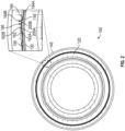
- a foil journal bearing (FJB) 100 which is a type of rotor-bearing system (RBS).
- the FJB 100 has a shaft 120, a top foil 130 surrounding the shaft 120 in the circumferential direction, a bump foil 140 surrounding the top foil 130 in the circumferential direction, and a bearing sleeve 145 surrounding the bump foil 140.
- the bump foil 140 is an annulus, e.g., it is a ring-shaped object, and it is formed with a profile defining corrugations 150, adjacently disposed, one after another, along the annulus.
- Each of the corrugations 150 includes a plurality of (or first and second) sidewalls 162, 164 that respectively converge from radial bottom (or inner) ends 162A, 164A adjacent to the top foil 130 to radial top (or outer) ends 162B, 164B adjacent to the bearing sleeve 45 to define a corrugation peak 190.
- the corrugations 150 may have sidewall undulations 200A, 200B, discussed in greater detail below.
- the corrugation 150 of the bump foil 140 may be in the form of a symmetric triangle waveform.
- a least one of the sidewalls 162, 164, such as sidewall 162, in at least one of the corrugations 150 includes one of the undulations 200A disposed midway between its bottom end 162A and top end 162B.
- the sidewalls 162, 164 of the same corrugation 150 respectively has first and second undulations 200A, 200B that may be shaped the same as each other so that, for simplicity, reference will be made to the undulation 200A on the sidewall 162.
- the undulation 200A defines a radial inner end 210A and a radial outer end 210B that are intermediate of the bottom end 162A and top end 162B of the sidewall 162.
- the undulation 200A may define a continuously curved profile, e.g., between its ends 210A, 210B.
- Each of the undulations 200A, 200B may extend or project outwardly, away from the top foil 130, i.e., toward the bearing sleeve 145 ( FIG. 2 ), by a distance from the sidewalls 162, 164 to undulation peaks 205A, 205B.
- Such distance from the sidewalls 162, 164 to the undulation peaks 205A, 205B may define an offset distance from the sidewalls 162 and164.
- the sidewalls can also be perforated, e.g., with a population of holes of different shapes, sizes and mutual arrangements, to have another set of design variables to control bending stiffness.
- the undulations can be uniform or non-unform.
- the embodiments provide permutations of bump foil undulations that allows the control the bump foil height, radii, number of undulations, shape of the undulations, and pitch of the undulations. These configurations provide a targeted dynamic stiffness and coulomb dampening for a given application.
- the undulations 200A, 200B may flex outwardly to increase contact with the bearing sleeve 145.
- the undulations may tend to extend and increase a radial height of the corrugation 150 and the undulations 200A, 200B may be drawn or biased inwardly relative to the location of its peaks 205A, 205B in the normal state ( FIG. 3 ).
- the outward and inward expansion of undulations increases contact pressure, hence increasing coulomb dampening.
- the outward expansion of the undulation also results in overall stiffness of the bearing. This general principle applies to all the undulation variations disclosed herein.
- FIG. 6 shows the bump foil 140 that may be utilized in the FJB 100.
- the bump foil 140 is against the top foil 130, and each of the corrugations 150 with the undulations 200A, 200B in its sidewalls 162, 164 has the configuration as shown in FIG. 3 .
- FIG. 7 shows the bump foil 140 that may be utilized in the FJB 100.
- the bump foil 140 is against the top foil 130, alternating the corrugations 150 have the undulations 200A, 200B in its sidewalls 162, 164 and are without the undulations.
- FIG. 8 shows a corrugation 150 of the bump foil 140 that may be utilized in the FJB 100.
- the corrugation 150 has the undulations 200A, 200B with the same shape and positioning on the sidewalls 162, 164 as shown in FIG. 3 .
- the corrugation 150 is shaped as a trapezoidal waveform.
- FIG. 9 shows a corrugation 150 of the bump foil 140 that may be utilized in the FJB 100.
- the corrugation 150 has the undulations 200A, 200B with the same shape and positioning on the sidewalls 162, 164 as shown in FIG. 3 .
- the corrugation 150 is shaped as a sinusoidal or quasi-sinusoidal waveform having curved segments along its profile, having either continuous or variable curvatures along the profile length.
- FIG. 12 shows a corrugation 150 of the bump foil 140 that may be utilized in the FJB 100.
- the corrugation 150 has the same shape as the corrugation in FIG. 3 .
- the undulations 200A, 200B on the sidewalls, 162, 164 have the same positioning on the sidewalls 162, 164 and are sized, from the inner to outer undulation ends 210A, 210B, the same as the undulations shown in FIG. 3 .
- the undulations 200A, 200B define a trapezoidal profile.
- the undulation peaks 205A, 205B of the undulations 200A, 200B may be the same size, e.g., with respect to the distance from the sidewalls 162, 164, as the undulation peaks 205A, 205B in FIG. 3 .
- FIG. 13 shows a corrugation 150 of the bump foil 140 that may be utilized in the FJB 100.
- the corrugation 150 has the same shape as the corrugation in FIG. 3 .
- the undulations 200A, 200B on the sidewalls, 162, 164 have the same positioning on the sidewalls 162, 164 and are sized, from the undulation inner to outer ends 210A, 210B, the same as the undulations shown in FIG. 3 .
- the undulations 200A, 200B each extend outwardly and define a profile that includes a plurality of linear segments 220A, 220B extending the sidewalls 162, 164 and a curved portion 230 joining the plurality of linear segments 220A, 220B.
- the size of the undulation peaks 205A, 205B of the undulations 200A, 200B in FIG. 13 , with respect to the offset distance from the sidewalls 162, 164, may be greater than the undulation peaks 205A, 205B in FIG. 3 .
- FIG. 14 shows a corrugation 150 of the bump foil 140 that may be utilized in the FJB 100.
- the corrugation 150 has the same shape as the corrugation in FIG. 3 .
- the undulations 200A, 200B on the sidewalls 162, 164 have the same positioning on the sidewalls 162, 164 as with FIG. 3 .
- the undulations 200A, 200B define an S-shaped profile, having two connected individual waves extending inwardly and outwardly, respectively, and extend, from the undulation inner to outer ends 210A, 210B, by a distance that is less than a length of the sidewalls 162, 164, though greater than the undulations 200A, 200B in FIG. 3 .
- the size of the undulation peaks 205A, 205B of the undulations 200A, 200B in FIG. 14 , with respect to the offset distance from the sidewalls 162, 164, may be less than the undulation peaks 205A, 205B in FIG. 3 .
- FIG. 15 shows a corrugation 150 of the bump foil 140 that may be utilized in the FJB 100.
- the corrugation 150 has the same shape as the corrugation in FIG. 3 .
- the undulations 200A, 200B on the sidewalls, 162, 164 have the same positioning on the sidewalls 162, 164.
- the undulations 200A, 200B define a profile, having more than two connected individual waves extending inwardly and outwardly, one after another, respectively, having arcuate vertexes and extend, from the undulation inner to outer ends 210A, 210B, by a distance that is less than a length of the sidewalls 162, 164, though greater than the undulations 200A, 200B in FIG. 3 .
- the size of the undulation peaks 205A, 205B of the undulations 200A, 200B in FIG. 15 , with respect to the distance from the sidewalls 162, 164, may be less than the undulation peaks 205A, 205B in FIG. 3 .
- FIG. 16 shows a corrugation 150 of the bump foil 140 that may be utilized in the FJB 100.
- the corrugation 150 has the same shape as the corrugation in FIG. 3 .
- the undulations 200A, 200B on the sidewalls, 162, 164 have the same positioning on the sidewalls 162, 164 and are sized, from the undulation inner to outer ends 210A, 210B, the same as the undulations shown in FIG. 3 .
- the undulations 200A, 200B have different shapes from each other.
- One undulation 200A may extend outwardly by a distance to its undulation peak 205A that is greater than the outward projection 205A of the undulation 200A of FIG. 3 .
- the other undulation 200B may extend outwardly by a distance to its undulation peak 205B that is less than the outward projection 205B of the undulation 200B of FIG. 3 .
- FIG. 17 shows a corrugation 150 of the bump foil 140 that may be utilized in the FJB 100.
- the corrugation 150 has an asymmetric shape though its undulation peak 190 may be at a same height, e.g., relative to the top foil 130, as the corrugation in FIG. 3 .
- the undulations 200A, 200B on the sidewalls, 162, 164 have the same positioning on the sidewalls 162, 164 and are sized and shaped the same as the undulations in FIG. 16 .
- FIG. 18 shows an apparatus 300 manufacturing the bump foil 140 with a trapezoidal shaped corrugation 150 with an internally extending undulations 200A on one of the sidewalls 162.
- Rollers 310, 320, each with set of teeth 330, 340 are configured to mesh with each other.
- One of the set of teeth 330 defines a cavity 350 while the other of the sets of teeth 340 defines a protrusion 360.
- the teeth 330, 340 are separated on each roller 310, 320 to define a smooth roller surface 370 therebetween.
- Running the bump foil 140 through the rollers 310, 320 imparts the bump foil 140 with the trapezoidal shaped corrugation 150 and with an internally extending undulations 200A on one of the sidewalls 162.
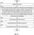
- FIG. 19 shows a method of manufacturing a foil journal bearing 100.
- the method includes obtaining bump foil.
- the method includes forming a bump foil 140 with the undulations 150 by rolling the bump foil 140 between a plurality of externally toothed rollers 310, 320 to impart a profile in the bump foil 140 that defines adjacently disposed corrugations 150.
- the corrugations 150 include sidewalls 162, 164 that extend from radial bottom ends 162A, 164A to radial top ends 162B, 164B that converge at a corrugation peak 190.
- At least one of the sidewalls 162 on at least one of the corrugations 150 includes one of the undulations 200A between the bottom end 162A and the top end 162B.
- the method includes surrounding a shaft 120 with a top foil 130.
- the method includes surrounding the top foil 130 with the bump foil 140.
- the method includes surrounding the bump foil 140 with the bearing sleeve 145.
- the embodiments provide configuration of a rotor-bearing system (RBS), which in the illustrated embodiments is a foil journal bearing (FJB) 100 having a bump foil 140 formed with a nonuniformity or undulations 200A, 200B in its corrugations 150, to enhance stiffness and damping of the FJB 100.
- RBS rotor-bearing system
- FJB foil journal bearing
- Modifying the non-uniformity in the corrugations 150 of the bump foil 140 results in tuning a stiffness of the bump foil 140, and improves coulomb damping, by increasing a contact surface area between the mating surfaces on the bump foil 140 and radially adjacent bearing sleeve 145.
- the configuration of the embodiments may be applied to foil thrust bearings (FTB), another type of RBS.
- FTB foil thrust bearings
- the disclosure provides different profiles for configurations of bump foil 140, with a top foil 130 having a uniform inner diameter and is radially exterior to a shaft of the bearing, and a bump foil 140 disposed between the top foil 130 and a bearing sleeve 145.
- the disclosed profiles of the corrugation 150 of the bump foil 140 provide for a self-adjusting of radial positioning when the bump foil 140 is installed, and pre-loaded, within the bearing sleeve 145.
- the bump foil 140 includes circumferentially adjacent corrugations 150, both of which defines sidewalls 162, 164 with a corrugation peak 190 or vertex at the junction between the sidewalls 162, 164.
- the corrugation peak 190 is radially spaced apart from the top foil 130 and radially against the bearing sleeve 145.
- the undulations 200A, 200B formed on the sidewalls 162, 164 of the corrugations 150 of the bump foil 140 improves an overall spring stiffness of the bump foil 140.
- Hydrodynamic pressure on the top foil 130 energizes the bump foil 140 and further increases the contact pressure between the undulated corrugations 150 and the mating surfaces between the bump foil 140 and the bearing sleeve 145. These pressures increase the dynamic coulomb damping of the rotor-bearing system (RBS).
Landscapes
- Engineering & Computer Science (AREA)
- General Engineering & Computer Science (AREA)
- Mechanical Engineering (AREA)
- Physics & Mathematics (AREA)
- Fluid Mechanics (AREA)
- Support Of The Bearing (AREA)
Abstract
Description
- The embodiments relate to bearings and more specifically to a foil bearing journal with a bump foil, configured for self-adjusting radial positioning.
- Foil journal bearing (FJB) have spring elements, also known as bump foils, that may have corrugated designs, consisting of combination of connected periodic shapes. These shapes in a diametric cross-sectional view can be schematically described as having a curved or flat bottom or top and planar side walls. Stiffnesses and load-capacities of an FJB may rely on a thickness, geometry and materials of the corrugations of the spring elements. Additionally, hydrodynamic coulomb damping of a FJB may rely on points of contact between the corrugations in the spring elements and the radially adjacent mating surface with the bearing sleeve of the FJB. Due to inevitable geometrical variability of fabricated foils and service misalignments, different segments of the foils can exhibit some non-uniformity of load transfer, especially, in the radial direction. Such non-uniformity may limit the stiffness and damping capability of the FJB to support operational dynamic loads of turbomachinery.
- Disclosed is a foil journal bearing, including: a shaft; a top foil surrounding the shaft in a circumferential direction; a corrugated bump foil surrounding the top foil in the circumferential direction, wherein the corrugated bump foil includes a plurality of adj acent corrugations that each include sidewalls that extend from a radial inner end to a radial outer end of the corrugated bump foil; and a bearing sleeve surrounding the corrugated bump foil, wherein: at least one of the sidewalls of at least one of the corrugations includes an undulation disposed between the outer and inner radial ends of the sidewall; and the undulation is defined by an undulation outer end and an undulation inner end.
- In addition to one or more aspects of the bearing or as an alternate, the corrugations define a triangular shape.
- In addition to one or more aspects of the bearing or as an alternate, the corrugations define a trapezoidal waveform.
- In addition to one or more aspects of the bearing or as an alternate, the corrugations define a sinusoidal or quasi-sinusoidal waveform having curved segments along its profile, having either continuous or variable curvatures along the profile length
- In addition to one or more aspects of the bearing or as an alternate, the undulation of the at least one of the corrugations extends outwardly from the at least one of the sidewalls, away from the top foil.
- In addition to one or more aspects of the bearing or as an alternate, both of the sidewalls of the at least one of the corrugations includes the undulations, wherein the undulations extend outwardly, away from the top foil.
- In addition to one or more aspects of the bearing or as an alternate, the undulation of the at least one of the sidewalls extends inwardly, toward the top foil.
- In addition to one or more aspects of the bearing or as an alternate, both of the sidewalls of the at least one of the corrugations includes the undulations, wherein the that extend inwardly, toward the top foil.
- In addition to one or more aspects of the bearing or as an alternate, each of the sidewalls of the at least one of the corrugations includes the undulations, wherein one of the undulations extends outwardly, away from the top foil, and another one of the undulations extend inwardly, toward the top foil.
- In addition to one or more aspects of the bearing or as an alternate, the undulation of the at least one of the corrugations defines a continuously curved profile.
- In addition to one or more aspects of the bearing or as an alternate, the undulation of the at least one of the corrugations defines a trapezoidal profile.
- In addition to one or more aspects of the bearing or as an alternate, the undulation of the at least one of the corrugations defines a profile that includes a plurality of linear segments extending away from the top foil and a curved portions joining the plurality of linear segments.
- In addition to one or more aspects of the bearing or as an alternate, the undulation of the at least one of the corrugations defines an S-shaped profile, including two connected individual waves extending inwardly and outwardly, respectively.
- In addition to one or more aspects of the bearing or as an alternate, the undulation of the at least one of the corrugations defines a profile, including more than two connected individual waves extending inwardly and outwardly, one after another, respectively.
- In addition to one or more aspects of the bearing or as an alternate, the corrugations define a symmetric triangular waveform; and the sidewalls of the at least one of the corrugations includes the undulations that extend outwardly, away from the top foil, and the undulations have the same shape as each other.
- In addition to one or more aspects of the bearing or as an alternate, the corrugations define a symmetric triangular waveform; and the sidewalls of the at least one of the corrugations includes the undulations, wherein the undulations extend outwardly, away from the top foil, and one of the undulations has a different shape than another one of the undulations.
- In addition to one or more aspects of the bearing or as an alternate, the corrugations define an asymmetric triangular waveform; and the sidewalls of the at least one of the corrugations includes the undulations that extend outwardly, away from the top foil, and have the same or a different shape from each other.
- In addition to one or more aspects of the bearing or as an alternate, the bump foil includes alternating corrugations with sidewall undulations and corrugations without sidewall undulations.
- Disclosed is a method of manufacturing a foil journal bearing, including: obtaining bump foil; and forming a bump foil with undulations by: rolling the bump foil between a pair of externally toothed rollers to impart a profile in the bump foil that defines adjacently disposed corrugations, wherein the corrugations include sidewalls that converge at a corrugation radial outer end, and at least one of the sidewalls of at least one of the corrugations include one of the undulations between the radial top and bottom ends of the sidewalls.
- In addition to one or more aspects of the method or as an alternate, the method includes surrounding a shaft with a top foil; surrounding the top foil with the bump foil; and surrounding the bump foil with a bearing sleeve.
- The present disclosure is illustrated by way of example and not limited in the accompanying figures in which like reference numerals indicate similar elements.
-
FIG. 1 shows a perspective view of a journal bearing according to an embodiment; -
FIG. 2 shows a front axial view and a detail of the journal bearing; -
FIG. 3 shows the bump foil with sidewall undulations in a normal state; -
FIG. 4 shows the bump foil with sidewall undulations in a radially compressed state; -
FIG. 5 shows the bump foil with sidewall undulations in a radially expanded state; -
FIG. 6 shows the bump foil with sidewall undulations in each corrugation; -
FIG. 7 shows the bump foil having both corrugations with and without sidewall undulations, e.g., with the undulations only in every other corrugation; -
FIG. 8 shows the bump foil with a trapezoidal corrugation; -
FIG. 9 shows the bump foil with a curved, e.g., quasi-sinusoidal corrugation; -
FIG. 10 shows the bump foil with inwardly contoured sidewall undulations; -
FIG. 11 shows the bump foil with inwardly and outwardly contoured sidewall undulations; -
FIG. 12 shows the bump foil with trapezoidal sidewall undulations; -
FIG. 13 shows the bump foil with sidewall undulations formed of linear and curved sections; -
FIG. 14 shows the bump foil with sidewall undulations having two individual waves, e.g., in a form of S-shaped undulations with two waves; -
FIG. 15 shows the bump foil with sidewall undulations having more than two individual waves, e.g., in a form of M-shaped undulations with three waves having curved peaks; -
FIG. 16 shows the bump foil with differently-shaped sidewall undulations in a corrugation shaped as a symmetric triangle; -
FIG. 17 shows the bump foil with differently-shaped sidewall undulations in a corrugation shaped as an asymmetric triangle; -
FIG. 18 shows a system for forming the bump foil with sidewall undulations in the corrugations; and -
FIG. 19 is a flowchart showing a method of manufacturing and assembling a foil journal bearing that includes the bump foil with sidewall undulations in the corrugations. - Aspects of the disclosed embodiments will now be addressed with reference to the figures. Aspects in any one figure is equally applicable to any other figure unless otherwise indicated. Aspects illustrated in the figures are for purposes of supporting the disclosure and are not in any way intended on limiting the scope of the disclosed embodiments. Any sequence of numbering in the figures is for reference purposes only.
- Turning to
FIGS. 1 and2 , a foil journal bearing (FJB) 100, which is a type of rotor-bearing system (RBS), is shown. The FJB 100 has ashaft 120, atop foil 130 surrounding theshaft 120 in the circumferential direction, abump foil 140 surrounding thetop foil 130 in the circumferential direction, and abearing sleeve 145 surrounding thebump foil 140. Thebump foil 140 is an annulus, e.g., it is a ring-shaped object, and it is formed with aprofile defining corrugations 150, adjacently disposed, one after another, along the annulus. Each of thecorrugations 150 includes a plurality of (or first and second)sidewalls ends top foil 130 to radial top (or outer)ends corrugation peak 190. Thecorrugations 150 may havesidewall undulations - As shown in
FIG. 3 , thecorrugation 150 of thebump foil 140 may be in the form of a symmetric triangle waveform. A least one of thesidewalls sidewall 162, in at least one of the corrugations 150 (e.g., a first corrugation 150), includes one of theundulations 200A disposed midway between itsbottom end 162A andtop end 162B. As shown inFIG. 3 , thesidewalls same corrugation 150 respectively has first andsecond undulations undulation 200A on thesidewall 162. - The
undulation 200A defines a radialinner end 210A and a radialouter end 210B that are intermediate of thebottom end 162A andtop end 162B of thesidewall 162. Theundulation 200A may define a continuously curved profile, e.g., between itsends top foil 130, i.e., toward the bearing sleeve 145 (FIG. 2 ), by a distance from thesidewalls undulation peaks sidewalls sidewalls 162 and164. - Variations of the geometrical implementations of corrugations with sidewall undulations with respect to sizing, curvatures, number of different sections of profiles, etc., are within the scope of this disclosure. The sidewalls can also be perforated, e.g., with a population of holes of different shapes, sizes and mutual arrangements, to have another set of design variables to control bending stiffness. Similarly, with respect to thickness, the undulations can be uniform or non-unform. As disclosed in greater detail below, the embodiments provide permutations of bump foil undulations that allows the control the bump foil height, radii, number of undulations, shape of the undulations, and pitch of the undulations. These configurations provide a targeted dynamic stiffness and coulomb dampening for a given application.
- As shown in
FIG. 4 , when thecorrugation 150 is compressed between thetop foil 130 and the bearing sleeve 145 (FIG. 2 ), theundulations bearing sleeve 145. Alternatively, if thecorrugation 150 expands radially outwardly, as shown inFIG. 5 , then the undulations may tend to extend and increase a radial height of thecorrugation 150 and theundulations peaks FIG. 3 ). The outward and inward expansion of undulations increases contact pressure, hence increasing coulomb dampening. The outward expansion of the undulation also results in overall stiffness of the bearing. This general principle applies to all the undulation variations disclosed herein. -
FIG. 6 shows thebump foil 140 that may be utilized in theFJB 100. Thebump foil 140 is against thetop foil 130, and each of thecorrugations 150 with theundulations sidewalls FIG. 3 .FIG. 7 shows thebump foil 140 that may be utilized in theFJB 100. Thebump foil 140 is against thetop foil 130, alternating thecorrugations 150 have theundulations sidewalls FIG. 8 shows acorrugation 150 of thebump foil 140 that may be utilized in theFJB 100. Thecorrugation 150 has theundulations sidewalls FIG. 3 . Thecorrugation 150, however, is shaped as a trapezoidal waveform.FIG. 9 shows acorrugation 150 of thebump foil 140 that may be utilized in theFJB 100. Thecorrugation 150 has theundulations sidewalls FIG. 3 . Thecorrugation 150, however, is shaped as a sinusoidal or quasi-sinusoidal waveform having curved segments along its profile, having either continuous or variable curvatures along the profile length. -
FIG. 10 shows acorrugation 150 of thebump foil 140 that may be utilized in theFJB 100. Thecorrugation 150 has the same shape as the corrugation shown inFIG. 3 , withundulations sidewalls FIG. 3 . While the overall sizes and shape of the undulations 200A, 200B is the same as that inFIG. 3 , theundulations sidewalls FIG. 11 , which is similar toFIG. 10 , one of theundulations 200A extends outwardly, away from thetop foil 130 as withFIG. 3 , and another one 200B extends inwardly, as withFIG. 10 . -
FIG. 12 shows acorrugation 150 of thebump foil 140 that may be utilized in theFJB 100. Thecorrugation 150 has the same shape as the corrugation inFIG. 3 . Theundulations sidewalls FIG. 3 . However, theundulations sidewalls FIG. 3 . -
FIG. 13 shows acorrugation 150 of thebump foil 140 that may be utilized in theFJB 100. Thecorrugation 150 has the same shape as the corrugation inFIG. 3 . Theundulations sidewalls outer ends FIG. 3 . However, theundulations linear segments sidewalls curved portion 230 joining the plurality oflinear segments FIG. 13 , with respect to the offset distance from thesidewalls FIG. 3 . -
FIG. 14 shows acorrugation 150 of thebump foil 140 that may be utilized in theFJB 100. Thecorrugation 150 has the same shape as the corrugation inFIG. 3 . Theundulations sidewalls sidewalls FIG. 3 . Theundulations outer ends sidewalls FIG. 3 . The size of the undulation peaks 205A, 205B of the undulations 200A, 200B inFIG. 14 , with respect to the offset distance from thesidewalls FIG. 3 . -
FIG. 15 shows acorrugation 150 of thebump foil 140 that may be utilized in theFJB 100. Thecorrugation 150 has the same shape as the corrugation inFIG. 3 . Theundulations sidewalls undulations outer ends sidewalls FIG. 3 . The size of the undulation peaks 205A, 205B of the undulations 200A, 200B inFIG. 15 , with respect to the distance from thesidewalls FIG. 3 . -
FIG. 16 shows acorrugation 150 of thebump foil 140 that may be utilized in theFJB 100. Thecorrugation 150 has the same shape as the corrugation inFIG. 3 . Theundulations sidewalls outer ends FIG. 3 . Theundulations undulation 200A may extend outwardly by a distance to itsundulation peak 205A that is greater than theoutward projection 205A of theundulation 200A ofFIG. 3 . Theother undulation 200B may extend outwardly by a distance to itsundulation peak 205B that is less than theoutward projection 205B of theundulation 200B ofFIG. 3 . -
FIG. 17 shows acorrugation 150 of thebump foil 140 that may be utilized in theFJB 100. Thecorrugation 150 has an asymmetric shape though itsundulation peak 190 may be at a same height, e.g., relative to thetop foil 130, as the corrugation inFIG. 3 . Theundulations sidewalls FIG. 16 . -
FIG. 18 shows an apparatus 300 manufacturing thebump foil 140 with a trapezoidal shapedcorrugation 150 with an internally extendingundulations 200A on one of thesidewalls 162.Rollers teeth teeth 330 defines acavity 350 while the other of the sets ofteeth 340 defines aprotrusion 360. Theteeth roller smooth roller surface 370 therebetween. Running thebump foil 140 through therollers bump foil 140 with the trapezoidal shapedcorrugation 150 and with an internally extendingundulations 200A on one of thesidewalls 162. -
FIG. 19 shows a method of manufacturing afoil journal bearing 100. As shown inblock 1905, the method includes obtaining bump foil. As shown inblock 1910, the method includes forming abump foil 140 with theundulations 150 by rolling thebump foil 140 between a plurality of externallytoothed rollers bump foil 140 that defines adjacently disposedcorrugations 150. Thecorrugations 150 includesidewalls corrugation peak 190. At least one of thesidewalls 162 on at least one of thecorrugations 150 includes one of theundulations 200A between thebottom end 162A and thetop end 162B. As shown inblock 1920, the method includes surrounding ashaft 120 with atop foil 130. As shown inblock 1930, the method includes surrounding thetop foil 130 with thebump foil 140. As shown inblock 1940, the method includes surrounding thebump foil 140 with thebearing sleeve 145. - The embodiments provide configuration of a rotor-bearing system (RBS), which in the illustrated embodiments is a foil journal bearing (FJB) 100 having a
bump foil 140 formed with a nonuniformity or undulations 200A, 200B in itscorrugations 150, to enhance stiffness and damping of theFJB 100. Modifying the non-uniformity in thecorrugations 150 of thebump foil 140 results in tuning a stiffness of thebump foil 140, and improves coulomb damping, by increasing a contact surface area between the mating surfaces on thebump foil 140 and radiallyadjacent bearing sleeve 145. As a result, there is an overall improved load-capacity of theFJB 100 to support dynamic operational loads of turbomachinery. It is to be appreciated that the configuration of the embodiments may be applied to foil thrust bearings (FTB), another type of RBS. - The disclosure provides different profiles for configurations of
bump foil 140, with atop foil 130 having a uniform inner diameter and is radially exterior to a shaft of the bearing, and abump foil 140 disposed between thetop foil 130 and abearing sleeve 145. The disclosed profiles of thecorrugation 150 of thebump foil 140 provide for a self-adjusting of radial positioning when thebump foil 140 is installed, and pre-loaded, within thebearing sleeve 145. Specifically, thebump foil 140 includes circumferentiallyadjacent corrugations 150, both of which defines sidewalls 162, 164 with acorrugation peak 190 or vertex at the junction between thesidewalls corrugation peak 190 is radially spaced apart from thetop foil 130 and radially against the bearingsleeve 145. Theundulations sidewalls corrugations 150 of thebump foil 140 improves an overall spring stiffness of thebump foil 140. Hydrodynamic pressure on thetop foil 130 energizes thebump foil 140 and further increases the contact pressure between the undulatedcorrugations 150 and the mating surfaces between thebump foil 140 and thebearing sleeve 145. These pressures increase the dynamic coulomb damping of the rotor-bearing system (RBS). The reaction force generated by theFJB 100, resulting from theundulations corrugations 150 and mating surfaces, between thebump foil 140 andbearing sleeve 145, improves a spring rate of the bump foil and hysteresis damping, also known as static damping, of theFJB 100. - The terminology used herein is for the purpose of describing particular embodiments only and is not intended to be limiting of the present disclosure. As used herein, the singular forms "a", "an" and "the" are intended to include the plural forms as well, unless the context clearly indicates otherwise. It will be further understood that the terms "comprises" and/or "comprising," when used in this specification, specify the presence of stated features, integers, steps, operations, elements, and/or components, but do not preclude the presence or addition of one or more other features, integers, steps, operations, element components, and/or groups thereof.
- Those of skill in the art will appreciate that various example embodiments are shown and described herein, each having certain features in the particular embodiments, but the present disclosure is not thus limited. Rather, the present disclosure can be modified to incorporate any number of variations, alterations, substitutions, combinations, sub-combinations, or equivalent arrangements not heretofore described, but which are commensurate with the scope of the present disclosure. Additionally, while various embodiments of the present disclosure have been described, it is to be understood that aspects of the present disclosure may include only some of the described embodiments. Accordingly, the present disclosure is not to be seen as limited by the foregoing description but is only limited by the scope of the appended claims.
Claims (15)
- A foil journal bearing, comprising:a shaft (120);a top foil (130) surrounding the shaft (120) in a circumferential direction;a corrugated bump foil (140) surrounding the top foil (130) in the circumferential direction, wherein the corrugated bump foil (140) includes a plurality of adjacent corrugations that each include sidewalls that extend from a radial inner end to a radial outer end of the corrugated bump foil (140); anda bearing sleeve surrounding the corrugated bump foil (140),wherein:at least one of the sidewalls of at least one of the corrugations includes an undulation disposed between the outer and inner radial ends of the sidewall; andthe undulation is defined by an undulation outer end and an undulation inner end.
- The bearing of claim 1, wherein:
the corrugations define a triangular shape, or wherein:
the corrugations define a trapezoidal waveform. - The bearing of claim 1, wherein:
the corrugations define a sinusoidal or quasi-sinusoidal waveform having curved segments along its profile, having either continuous or variable curvatures along the profile length. - The bearing of any preceding claim, wherein:
the undulation of the at least one of the corrugations extends outwardly from the at least one of the sidewalls, away from the top foil (130) or wherein:
the undulation of the at least one of the sidewalls extends inwardly, toward the top foil (130). - The bearing of any preceding claim, wherein:both of the sidewalls of the at least one of the corrugations includes the undulations, wherein the undulations extend outwardly, away from the top foil (130),or wherein:
both of the sidewalls of the at least one of the corrugations includes the undulations, wherein the that extend inwardly, toward the top foil (130). - The bearing of any of claims 1 to 5, wherein:
each of the sidewalls of the at least one of the corrugations includes the undulations, wherein one of the undulations extends outwardly, away from the top foil (130), and another one of the undulations extend inwardly, toward the top foil (130). - The bearing of any preceding claim, wherein:
the undulation of the at least one of the corrugations defines a continuously curved profile, or wherein:
the undulation of the at least one of the corrugations defines a trapezoidal profile. - The bearing of any of claims 1 to 6, wherein:
the undulation of the at least one of the corrugations defines a profile that includes a plurality of linear segments extending away from the top foil (130) and a curved portions joining the plurality of linear segments. - The bearing of any of claims 1 to 6, wherein:
the undulation of the at least one of the corrugations defines an S-shaped profile, comprising two connected individual waves extending inwardly and outwardly, respectively. - The bearing of any of claims 1 to 6, wherein:
the undulation of the at least one of the corrugations defines a profile, comprising more than two connected individual waves extending inwardly and outwardly, one after another, respectively. - The bearing of claim 1, wherein:the corrugations define a symmetric triangular waveform; andthe sidewalls of the at least one of the corrugations includes the undulations that extend outwardly, away from the top foil (130), and the undulations have the same shape as each other, or wherein:the corrugations define a symmetric triangular waveform; andthe sidewalls of the at least one of the corrugations includes the undulations, wherein the undulations extend outwardly, away from the top foil (130), and one of the undulations has a different shape than another one of the undulations.
- The bearing of claim 1, wherein:the corrugations define an asymmetric triangular waveform; andthe sidewalls of the at least one of the corrugations includes the undulations that extend outwardly, away from the top foil (130), and have the same or a different shape from each other.
- The bearing of claim 1, wherein:
the bump foil (140) includes alternating corrugations with sidewall undulations and corrugations without sidewall undulations. - A method of manufacturing a foil journal bearing, comprising:obtaining bump foil (140); andforming a bump foil (140) with undulations by:rolling the bump foil (140) between a pair of externally toothed rollers to impart a profile in the bump foil (140) that defines adjacently disposed corrugations,wherein the corrugations include sidewalls that converge at a corrugation radial outer end, and at least one of the sidewalls of at least one of the corrugations include one of the undulations between the radial top and bottom ends of the sidewalls.
- The method of claim 14, further comprising:surrounding a shaft (120) with a top foil (130);surrounding the top foil (130) with the bump foil (140); andsurrounding the bump foil (140) with a bearing sleeve.
Applications Claiming Priority (1)
| Application Number | Priority Date | Filing Date | Title |
|---|---|---|---|
| US18/186,430 US12264704B2 (en) | 2023-03-20 | 2023-03-20 | Foil journal bearing with bump foil configured for self-adjusted radial positioning |
Publications (1)
| Publication Number | Publication Date |
|---|---|
| EP4435279A1 true EP4435279A1 (en) | 2024-09-25 |
Family
ID=90368288
Family Applications (1)
| Application Number | Title | Priority Date | Filing Date |
|---|---|---|---|
| EP24164894.8A Pending EP4435279A1 (en) | 2023-03-20 | 2024-03-20 | Foil journal bearing with bump foil configured for selfadjusted radial positioning |
Country Status (2)
| Country | Link |
|---|---|
| US (1) | US12264704B2 (en) |
| EP (1) | EP4435279A1 (en) |
Citations (7)
| Publication number | Priority date | Publication date | Assignee | Title |
|---|---|---|---|---|
| GB566572A (en) * | 1943-02-20 | 1945-01-04 | Sk Wellman Co | Improvements in or relating to friction devices and method of making same |
| US4295689A (en) * | 1979-08-30 | 1981-10-20 | United Technologies Corporation | Adjustable clearance foil journal bearing and method of manufacturing foil element therefor |
| US4415281A (en) * | 1981-11-23 | 1983-11-15 | United Technologies Corporation | Hydrodynamic fluid film bearing |
| US6964522B2 (en) * | 2004-01-22 | 2005-11-15 | Honeywell International Inc. | Hydrodynamic journal foil bearing system |
| US20070047858A1 (en) * | 2005-08-31 | 2007-03-01 | Honeywell International, Inc. | Foil journal bearing with bilinear stiffness spring |
| US9109622B2 (en) * | 2012-11-19 | 2015-08-18 | Honeywell International Inc. | Rotor support structures including anisotropic foil bearings or anisotropic bearing housings and methods for controlling non-synchronous vibrations of rotating machinery using the same |
| US20190101163A1 (en) * | 2017-09-29 | 2019-04-04 | Saint-Gobain Performance Plastics Rencol Limited | Tolerance ring |
Family Cites Families (7)
| Publication number | Priority date | Publication date | Assignee | Title |
|---|---|---|---|---|
| US5584582A (en) | 1994-12-15 | 1996-12-17 | Air Products And Chemicals, Inc. | Bump foil design for improved damping and load capacity from compliant foil gas bearings |
| US6698930B2 (en) * | 2000-12-01 | 2004-03-02 | Mitsubishi Heavy Industries, Ltd. | Foil gas bearing |
| KR100573384B1 (en) | 2004-02-14 | 2006-04-25 | 한국터보기계(주) | Radial Foil Bearing |
| US7108488B2 (en) | 2004-03-26 | 2006-09-19 | Honeywell International, Inc. | Turbocharger with hydrodynamic foil bearings |
| US8147143B2 (en) * | 2004-09-22 | 2012-04-03 | Hamilton Sundstrand Corporation | Bump foil hydrodynamic thrust bearing |
| US9309925B2 (en) | 2009-10-06 | 2016-04-12 | Mohawk Innovative Technology, Inc. | High speed machining center |
| KR102456838B1 (en) | 2017-11-21 | 2022-10-21 | 한온시스템 주식회사 | Air foil journal bearing |
-
2023
- 2023-03-20 US US18/186,430 patent/US12264704B2/en active Active
-
2024
- 2024-03-20 EP EP24164894.8A patent/EP4435279A1/en active Pending
Patent Citations (7)
| Publication number | Priority date | Publication date | Assignee | Title |
|---|---|---|---|---|
| GB566572A (en) * | 1943-02-20 | 1945-01-04 | Sk Wellman Co | Improvements in or relating to friction devices and method of making same |
| US4295689A (en) * | 1979-08-30 | 1981-10-20 | United Technologies Corporation | Adjustable clearance foil journal bearing and method of manufacturing foil element therefor |
| US4415281A (en) * | 1981-11-23 | 1983-11-15 | United Technologies Corporation | Hydrodynamic fluid film bearing |
| US6964522B2 (en) * | 2004-01-22 | 2005-11-15 | Honeywell International Inc. | Hydrodynamic journal foil bearing system |
| US20070047858A1 (en) * | 2005-08-31 | 2007-03-01 | Honeywell International, Inc. | Foil journal bearing with bilinear stiffness spring |
| US9109622B2 (en) * | 2012-11-19 | 2015-08-18 | Honeywell International Inc. | Rotor support structures including anisotropic foil bearings or anisotropic bearing housings and methods for controlling non-synchronous vibrations of rotating machinery using the same |
| US20190101163A1 (en) * | 2017-09-29 | 2019-04-04 | Saint-Gobain Performance Plastics Rencol Limited | Tolerance ring |
Also Published As
| Publication number | Publication date |
|---|---|
| US20240318684A1 (en) | 2024-09-26 |
| US12264704B2 (en) | 2025-04-01 |
Similar Documents
| Publication | Publication Date | Title |
|---|---|---|
| US3976340A (en) | Device for mounting a radial rolling bearing | |
| US4223958A (en) | Modular compliant hydrodynamic bearing with overlapping bearing sheet | |
| US9470260B2 (en) | Thrust bearing assembly | |
| CN114382775A (en) | Gas dynamic pressure radial bearing, compressor and engine | |
| CN214788551U (en) | Radial foil dynamic pressure air bearing with good damping effect | |
| EP0627054B1 (en) | Lip seal with radially compressible support band | |
| CN114215842B (en) | Gas dynamic pressure bearing, compressor and engine | |
| US5743660A (en) | Cage for roller bearing assembly | |
| US3758123A (en) | Omega seal | |
| US12264704B2 (en) | Foil journal bearing with bump foil configured for self-adjusted radial positioning | |
| US4222618A (en) | Compliant hydrodynamic fluid bearing with resilient support matrix | |
| CN211398262U (en) | Dynamic pressure gas radial bearing and power equipment | |
| KR102158829B1 (en) | Wave generator and wave gear device | |
| CN112639313B (en) | Thrust foil bearings | |
| JP2019108908A (en) | Attachment structure of rolling bearing | |
| CN216951265U (en) | Radial bump foil, dynamic pressure air-float radial bearing, motor and air compressor | |
| JP6651397B2 (en) | Foil bearing | |
| KR20130060284A (en) | Rolling bearing for a shaft | |
| JPS6215540Y2 (en) | ||
| US3099455A (en) | Piston ring assembly | |
| CN117432707B (en) | Radial air foil bearing and shafting | |
| JP2008232309A (en) | Roller bearing | |
| US7354032B2 (en) | Plate spring, which is prevented from being axially displaced on a circular cylindrical surface of a receiving body | |
| JP3068440U (en) | Roller bearing | |
| JP2007198518A (en) | Roller and roller bearing |
Legal Events
| Date | Code | Title | Description |
|---|---|---|---|
| PUAI | Public reference made under article 153(3) epc to a published international application that has entered the european phase |
Free format text: ORIGINAL CODE: 0009012 |
|
| STAA | Information on the status of an ep patent application or granted ep patent |
Free format text: STATUS: THE APPLICATION HAS BEEN PUBLISHED |
|
| AK | Designated contracting states |
Kind code of ref document: A1 Designated state(s): AL AT BE BG CH CY CZ DE DK EE ES FI FR GB GR HR HU IE IS IT LI LT LU LV MC ME MK MT NL NO PL PT RO RS SE SI SK SM TR |
|
| STAA | Information on the status of an ep patent application or granted ep patent |
Free format text: STATUS: REQUEST FOR EXAMINATION WAS MADE |
|
| 17P | Request for examination filed |
Effective date: 20250324 |
|
| GRAP | Despatch of communication of intention to grant a patent |
Free format text: ORIGINAL CODE: EPIDOSNIGR1 |
|
| STAA | Information on the status of an ep patent application or granted ep patent |
Free format text: STATUS: GRANT OF PATENT IS INTENDED |
|
| RIC1 | Information provided on ipc code assigned before grant |
Ipc: F16C 17/02 20060101AFI20260303BHEP |
|
| INTG | Intention to grant announced |
Effective date: 20260330 |