EP4435239A1 - A method of installing an underwater energy recovery system in a body of water and related fluid production installation - Google Patents
A method of installing an underwater energy recovery system in a body of water and related fluid production installation Download PDFInfo
- Publication number
- EP4435239A1 EP4435239A1 EP23305411.3A EP23305411A EP4435239A1 EP 4435239 A1 EP4435239 A1 EP 4435239A1 EP 23305411 A EP23305411 A EP 23305411A EP 4435239 A1 EP4435239 A1 EP 4435239A1
- Authority
- EP
- European Patent Office
- Prior art keywords
- equipment
- module
- evaporator
- working fluid
- fluid
- Prior art date
- Legal status (The legal status is an assumption and is not a legal conclusion. Google has not performed a legal analysis and makes no representation as to the accuracy of the status listed.)
- Pending
Links
Images


Classifications
-
- F—MECHANICAL ENGINEERING; LIGHTING; HEATING; WEAPONS; BLASTING
- F01—MACHINES OR ENGINES IN GENERAL; ENGINE PLANTS IN GENERAL; STEAM ENGINES
- F01K—STEAM ENGINE PLANTS; STEAM ACCUMULATORS; ENGINE PLANTS NOT OTHERWISE PROVIDED FOR; ENGINES USING SPECIAL WORKING FLUIDS OR CYCLES
- F01K25/00—Plants or engines characterised by use of special working fluids, not otherwise provided for; Plants operating in closed cycles and not otherwise provided for
- F01K25/08—Plants or engines characterised by use of special working fluids, not otherwise provided for; Plants operating in closed cycles and not otherwise provided for using special vapours
- F01K25/10—Plants or engines characterised by use of special working fluids, not otherwise provided for; Plants operating in closed cycles and not otherwise provided for using special vapours the vapours being cold, e.g. ammonia, carbon dioxide, ether
Definitions
- the present invention concerns a method of installing an underwater energy recovery system in thermal connection with a fluid production and/or injection piping laying on the bottom of a body of water, the underwater energy recovery system comprising an organic Rankine cycle having equipment comprising an evaporator to evaporate the working fluid, and optionally a pre-heater to heat the working fluid upstream of the evaporator, the equipment further comprising a turbine coupled to a power generator connected to an electrical controller, to expand the working fluid after evaporation, a condenser to condense the working fluid after expansion, a drum to collect the condensed working fluid and a pump to compress the collected working fluid, the method comprising lowering the equipment in the body of water and thermally connecting at least a pipe of the fluid production and/or injection piping to the evaporator and advantageously to the pre-heater.
- Hydrocarbon production installations require electrical power to be operated.
- subsea ground architectures use electrical power to operate various equipment such as pumps, gas injection devices, valves, etc.
- part of the produced fluid is used as fuel to generate electrical power which is conveyed to the bottom of the body of water.
- Hydrocarbon production installation often produce fluids which have a temperature significantly above the ambient temperature.
- the flow which is extracted from the reservoir is quite warm, since the reservoir is often located deep in the ground.
- the hydrocarbon production flow therefore conveys a thermal energy, which is totally lost at the surface of the well or downstream the well location.
- Thermal energy can be recovered using an organic Rankine cycle (ORC) to convert this energy into electricity through a turbine/alternator.
- ORC organic Rankine cycle
- An organic Rankine cycle uses a heat source that heats up and vaporizes in an evaporator an intermediate working fluid, used to drive a turbine. Downstream the turbine, the working fluid at low pressure (superheated or in bi-phasic phase) is fully condensed by a cold source prior being pressure boosted through a circulating pump. This circulating pump then sends back the intermediate fluid to the evaporator.
- FR 2 738 872 discloses such an energy recovery system located at the bottom of a body of water.
- the energy recovery system uses, as a heat source, production flow lines laying on the ground at the bottom of the body of water.
- a thermal cycle is carried out to recover heat from the fluid flowing in the production lines, to partially transform the heat into mechanical energy and/or electrical energy.
- One aim of the invention is therefore to provide an energy recovery system from hot fluids produced from the ground in an offshore fluid production installation, which supplies high electrical power, while being simple to put in place.
- the subject matter of the invention is an installation method of the above-mentioned type, characterized in that lowering the equipment comprises lowering a first support module comprising a main frame and a first part of the equipment of the organic Rankine cycle borne by the main frame and lowering at least a second equipment module comprising at least a second part of the equipment of the organic Rankine cycle, laying the second equipment module on the first support module and connecting the first part of the equipment to the second part of the equipment.
- the method according to the invention may comprise one or more of the following feature(s), taken alone, or according to any technical feasible combination:
- the invention also concerns a fluid production installation comprising:
- a first hydrocarbon production installation 10 having an underwater energy recovery system 20 put in place by an installation method according to the invention is shown in figure 1 .
- the hydrocarbon production installation 10 is located offshore. It comprises a bottom assembly 11A located at the bottom 16 of a body of water 12, a surface assembly 11B located at the surface of the body of water 12 and a connection assembly 11C fluidly and electrically connecting the bottom assembly 11A to the surface assembly 11B.
- the hydrocarbon production installation 10 comprises at least a production well 14 connecting a downhole reservoir (not shown) to the bottom 16 of the body of water 12.
- the bottom assembly 11A comprises a fluid production and/or injection piping assembly 18 laying on the bottom 16 of the body of water 12 and the underwater energy recovery system 20, thermally connected to the fluid production and/or injection piping assembly 18.
- the piping assembly 18 comprises in particular at least a wellhead 22 closing each well 14, advantageously a high integrity pressure production system 24 (or "HIPPS"), and flow lines 26 connecting each wellhead 26 to at least a fluid collection manifold 28 connected to the connection assembly 11C.
- HPPS high integrity pressure production system
- the fluid production and/or injection piping assembly 18 further comprises two tappings 30A, 30B configured to connect to a flow line bypass 32 carried by the energy recovery system 20, as will be explained below.
- connection assembly 11C comprises at least a riser 34 connecting the or each manifold 28 to the surface assembly 11B to transport fluid recovered from the well 14 and at least an umbilical 36, to carry a potential excess of electrical energy produced by the energy recovery system 20 to the surface assembly 11C.
- the surface assembly 11B is for example a platform, a barge, a vessel such as a FPSO (Floating Production Storage and Offloading) or a FSRU (Floating Storage and Regasification Unit) or to onshore facilities (subsea to shore case).
- FPSO Floating Production Storage and Offloading
- FSRU Floating Storage and Regasification Unit
- the energy recovery system 20 is based on an organic Rankine cycle 50 which thermally interacts with the fluid production and/or injection piping 18 through the bypass 32.
- the cycle 50 comprises equipment 52 processing a working fluid in the cycle 50.
- the equipment 52 here comprises a preheater 54, to preheat the working fluid, an evaporator 56, to evaporate the working fluid preheated in the preheater 54, a turbine 58 to expand the evaporated working fluid, and a generator 60 coupled to the turbine 58 along with a transformer 62 and a controller 64.
- the equipment 52 further comprises a condenser 66 to condense the working fluid after expansion, a drum 68 to collect the condensed working fluid and a pump 70 to increase the pressure of the collected working fluid and to direct it towards the preheater 54.
- the preheater 54 when present, is placed in a heat relationship with the bypass 32, the bypass 32 receiving production fluid circulating from an upstream tapping 30A to a downstream tapping 30B.
- the evaporator 56 is configured to place in a heat exchange relationship the production fluid circulating in the bypass 32 with the working fluid downstream of the upstream tapping 30A and upstream of the preheater 54.
- the preheater 54 and the evaporator 56 both have an elongated tubular shape. They are preferably placed on top of one another, parallel to an elongation axis A-A'.
- the turbine 58 is a gas expansion turbine having a rotor rotating around a rotation axis B-B'.
- the rotation axis B-B' is parallel to the elongation axis A-A'.
- the transformer 62 is electrically connected to the generator 60 through the controller 64.
- the controller 64 and the generator 60 extend perpendicularly to the rotation axis B-B' of the turbine 58, in alignment with the elongation axis A-A' of the preheater 54 and of the evaporator 56.
- the transformer 62 is equipped with two terminals 72A, 72B configured to receive terminals of at least an umbilical 36 to connect to the surface assembly 11B and/or to utilities of the fluid production and/or injection piping assembly 18, such as pumps, gas injection devices, and/or valves.
- the condenser 66 for example comprises a bundle of tubes 74 held in a frame 76. It allows contactless heat transfer between water from the body of water 12 circulating externally to the tubes 74, and working fluid circulating within the tubes 74.
- the condenser 66 extends along a condenser axis C-C' to which the tubes 74 are advantageously parallel.
- the condenser axis C-C' is parallel or coaxial with the rotation axis B-B' of the turbine 58, in an axial prolongation of the turbine 58. It is parallel and adjacent to the elongation axis A-A' of the preheater 54 and of the evaporator 56.
- the drum 68 extends vertically in an axial prolongation of the condenser 66, opposed to the turbine 58.
- the pump 70 is housed in the axial prolongation of the elongation axis A-A' of the evaporator 56, perpendicularly to the drum 68.
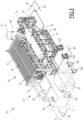
- the energy recovery system 20 comprises a first support module 80, an electrical module 82, and an exchanger module 84, the modules 80, 82 being borne by the first support module 80.
- Each module 80, 82, 84 comprises at least part of the equipment 52 of the organic Rankine cycle 50.
- Each module 80, 82, 84 is an independent structure movable in one piece independently of the other modules. All parts borne by each module 80, 82, 84 are jointly movable with the module 80, 82, 84 independently of the other modules.
- the support module 80 comprises a main frame 90, a main piping 92 and a first part of the equipment 52.
- the first part of the equipment here comprises the condenser 66, the drum 68, and the pump 70.
- the main frame 90 for example comprises a lower support having a lower surface laying on the bottom 16 of the body of water 12 and an upper surface onto which the equipment 52 of the support module 80 is mounted. It may comprise a protecting cover (not shown).
- the upper surface of the main frame 90 lower support also receives the electrical module 82 and the exchanger module 84 which are laid onto it during the installation of the energy recovery system 20 using the method according to the invention.
- the main piping 92 connects the first part of the equipment 52 located on the support module 80 with other parts of the equipment 52 located on other modules 82, 84.
- the electrical module 82 also comprises a frame, holding a second part of the equipment 52 including the turbine 58, the generator 60, the transformer 62 and the controller 64.
- the frame of the electrical module 82 holding the second part of the equipment 52 is movable independently of the support module 80.
- the second part of the equipment 52 is thus movable jointly with the frame of the electrical module 82 to be put in place on the support module 80.
- the exchanger module 84 also comprises a frame 96 holding a third part of the equipment 52 including the preheater 54 and the evaporator 56, advantageously on top of one another. It further comprises piping 98 to connect to the other modules 80, 82.
- the frame of the exchanger module 84 holding the third part of the equipment 52 is movable independently of the support module 80 and of the electrical module 82.
- the third part of the equipment 52 is thus movable jointly with the frame of the exchanger module 84 82 to be put in place on the support module 80.
- the support module 80, the electrical module 82 and the exchanger module 84 preferably each weigh less than 200 T.
- MSV Maneuver or Multipurpose Support Vessel
- the maximum dimension of the support module 80 is advantageously less than 20 m, in particular comprised between 12 m and 18 m.
- the length of the support module 80 is comprised between 10 m and 20 m
- the width of the main module 80 is comprised between 5 m and 15 m
- the height of the support module 80 is comprised between 1 m and 10 m.
- the weight of the support module 80 is generally greater than 100 T, and is comprised for example between 150 T and 170 T.
- the maximum dimension of the electrical module 82 is generally smaller than 10 m.
- the length of the electrical module 82 is comprised between 5 m and 10 m
- the width of the electrical module 82 is comprised between 0.5 m and 5 m
- the height of the electrical module 82 is comprised between 1 m and 5 m.
- the weight of the electrical module 82 is smaller than 100 T, it is for example comprised between 10 T and 50 T.
- the maximum dimension of the exchanger module 84 is generally smaller than 10 m.
- the length of the exchanger module 84 is comprised between 5 m and 10 m
- the width of the exchanger module 84 is comprised between 0.5 m and 5 m
- the height of the exchanger module 84 is comprised between 1 m and 5 m.
- the weight of the exchanger module 84 is smaller than 100 T, it is for example comprised between 40 T and 70 T.
- an installation vessel is loaded with the support module 80 holding at least a first part of the equipment 52.
- the vessel is for example a MSV. It comprises a crane having a maximum capacity for example smaller than 300 T.
- the support module 80 is lowered in the body of water 12 as a single unit carrying for example, the condenser 66, the drum 68, and the pump 70.
- the lower surface of the main frame 90 is laid on the bottom 16 of the body of water 12 in the vicinity of a flow line 26.
- the electrical module 82 is loaded in the laying vessel, in particular a MSV having a crane for example with a capacity of less than 300 T.
- the electrical module 82 carrying the turbine 58, the generator 60 and the transformer 62 is thereafter lowered in the body of water 12 as a single unit. It is laid on the main frame of the support module 90, adjacent to the condenser 66, advantageously with the rotation axis A-A' of the turbine 68 parallel and/or coaxial with the condenser axis C-C'.
- the exchanger module 84 is loaded on a laying vessel, in particular a MSV having a crane for example with a capacity of less than 300 T.
- the exchanger module 84 is then lowered as a single unit in the body of water 12, including the frame 96 bearing the preheater 54, the evaporator 56 and preferably the bypass 32.
- the frame 96 of the exchanger module 84 is laid on the support module 80, adjacent to the condenser 66 between the electrical module 82 on one side, the pump 70 on the other side.
- the elongation axis A-A' of the preheater 54 and of the evaporator 56 is placed parallel to the rotation axis B-B' and also to the condenser axis C-C' in alignment with the transformer 62 and the pump 70.
- the connectors 32A, 32B of the bypass are then connected to the tappings 30A, 30B on the flowline 26 such that warm fluid recovered in the flowline 26 can flow in the bypass 32 through the evaporator 56 and the preheater 54.
- Piping present on each of the modules 80, 82 and 84 is connected to allow the working fluid to cycle from the preheater 54, to the evaporator 56, the turbine 58, the condenser 66, the drum 68 and the pump 70.
- An umbilical 36 is connected to one of the terminals 72A and to utilities in the fluid production and/or piping assembly 18 to power the fluid production and/or injection piping assembly.
- another umbilical 36 is connected to another terminal 72B to the surface assembly 11B, to power utilities on the surface assembly 11B or onshore.
- fluid from the flowline 26 flows through the bypass 32 at an inlet temperature generally greater than 100°C and preferably comprised between 120°C and 150°C.
- 100% of the working fluid evaporates in the evaporator 56.
- the working fluid in gas phase is then introduced in the turbine 58 at a pressure advantageously greater than 5 bar and comprised generally between 10 bar and 15 bar to be expanded to a pressure advantageously smaller than 5 bar and generally comprised between 1.5 bar and 3.5 bar.
- the expansion of the working fluid rotates the rotor of the turbine 58 about the rotation axis A-A' to generate electrical power in the generator 60.
- the electrical power is transmitted to the transformer 62 to increase its tension in particular to transport it to the surface assembly 11B.
- the whole electrical power of the utilities present in the fluid production and/or injection piping assembly 18 is provided by the generator 60, and if an excess power remains, it is transmitted to the surface assembly 11B via an umbilical 36.
- the expanded gaseous working fluid is then passed through the condenser 66, where it heats exchanges with water from the body of water 12 to condense the working fluid.
- the condensed working fluid is recovered in the drum 68, before being pumped by the pump to increase its pressure to a pressure advantageously greater than 5 bars. It is then directed to the preheater 54.
- the dimensions of the equipment 52 contained in the organic Rankine cycle can be greatly increased, which allows a significant power recovery, for example greater than 500 kW up to several MW.
- the underwater energy recovery system 20 remains nevertheless very compact, in particular due to the specific alignment of the rotation axis B-B' of the turbine 58, of the elongation axis A-A' of the evaporator 56/ preheater 54, and of the condenser axis C-C'.
- the modular structure also allows an easy replacement or maintenance of one of the modules 80, 82, 84, without having to completely raise the underwater energy recovery system 20.
- the system 20 is thus very efficient in heat recovery and transformation, yet very easy to install and maintain with laying vessels of smaller capacities and greater availability.
- FIG. 5 An alternate modular underwater energy recovery system 20 is shown in figure 5 .
- the recovery system of figure 5 differs from the system of figure 4 in that the condenser 66 is not held by the support module 80.
- the condenser 66 is here borne by an additional condenser module 100.
- the condenser module 100 is thus movable as one single unit, independently of the other modules 80, 82, 84.
- the installation of the energy recovery system 20 shown in figure 5 only differs from the installation of the energy recovery system 20 shown in figure 4 in that the condenser module 100 is put in place independently of the other modules 80, 82, 84. It is laid in one piece on the support module 80, preferably with the condenser axis C-C' parallel to the rotation axis B-B' in an axial prolongation of the turbine 58.
- Such a configuration allows the energy recovery system 20 to produce a greater electrical power, for example greater than 100 kW, in particular comprised between 500 kW and 10MW.
- the weight of the support module 80 can then be more than 200 T, such as between 250 T and 1500 T. As such, a heavy lift vessel (HLV) has to be used to lay the support module 80.
- the remaining modules 82, 84, 100 can still be laid with a MSV as described above.
- the maximal dimension of the main module 80 can be greater than 15 m, and comprised between 18 m and 30 m.
- the main module 80 may have a length comprised between 18 m and 30 m, a width comprised between 5 m and 20 m, and a height comprised between 5 m and 15 m.
- the electrical module 82 may have a maximum dimension comprised between 5 m and 10 m. It may have a length comprised between 5 m and 10 m, a width comprised between 2 m and 8 m, and a height comprised between 1 m and 5 m.
- the exchanger module 84 may have a maximum dimension comprised between 5 m and 15 m. It may have a length comprised between 5 m and 15 m, a width comprised between 0.5 m and 5 m, and a height comprised between 2 m and 5 m.
- the condenser module 100 may have a maximum dimension comprised between 10 m and 20 m. It may comprise a length comprised between 10 m and 20 m, a width comprised between 2 m and 10 m, and a height comprised between 2 m and 8 m.
- a heat exchange loop 102 comprising a heat exchange fluid thermally connects the manifold 28 to the preheater 54 and/or the evaporator 56 to transfer heat from the fluid contained in the manifold 28 to the preheater 54 and/or the evaporator 56.
Landscapes
- Engineering & Computer Science (AREA)
- Chemical & Material Sciences (AREA)
- Combustion & Propulsion (AREA)
- Mechanical Engineering (AREA)
- General Engineering & Computer Science (AREA)
- Engine Equipment That Uses Special Cycles (AREA)
Abstract
Description
- The present invention concerns a method of installing an underwater energy recovery system in thermal connection with a fluid production and/or injection piping laying on the bottom of a body of water, the underwater energy recovery system comprising an organic Rankine cycle having equipment comprising an evaporator to evaporate the working fluid, and optionally a pre-heater to heat the working fluid upstream of the evaporator, the equipment further comprising a turbine coupled to a power generator connected to an electrical controller, to expand the working fluid after evaporation, a condenser to condense the working fluid after expansion, a drum to collect the condensed working fluid and a pump to compress the collected working fluid,
the method comprising lowering the equipment in the body of water and thermally connecting at least a pipe of the fluid production and/or injection piping to the evaporator and advantageously to the pre-heater. - Hydrocarbon production installations require electrical power to be operated. For example, subsea ground architectures use electrical power to operate various equipment such as pumps, gas injection devices, valves, etc.
- In traditional installations, part of the produced fluid is used as fuel to generate electrical power which is conveyed to the bottom of the body of water.
- However, energy production based on hydrocarbon combustion reduces the amount of hydrocarbons which are available for the final client, and hence the overall productivity and efficiency of the field. Moreover, combustion of hydrocarbons in a generator produces greenhouse gases, whose emissions have to be reduced when possible.
- Hydrocarbon production installation often produce fluids which have a temperature significantly above the ambient temperature. The flow which is extracted from the reservoir is quite warm, since the reservoir is often located deep in the ground.
- The hydrocarbon production flow therefore conveys a thermal energy, which is totally lost at the surface of the well or downstream the well location.
- Thermal energy can be recovered using an organic Rankine cycle (ORC) to convert this energy into electricity through a turbine/alternator.
- An organic Rankine cycle uses a heat source that heats up and vaporizes in an evaporator an intermediate working fluid, used to drive a turbine. Downstream the turbine, the working fluid at low pressure (superheated or in bi-phasic phase) is fully condensed by a cold source prior being pressure boosted through a circulating pump. This circulating pump then sends back the intermediate fluid to the evaporator.
-
FR 2 738 872 - A thermal cycle is carried out to recover heat from the fluid flowing in the production lines, to partially transform the heat into mechanical energy and/or electrical energy.
- Such a system partially recovers the hydrocarbon production flow thermal energy, but yet produces a limited electrical power. Moreover, the system requires very specific equipment to be placed around each production line, which is not always available on existing fields, or which significantly increases the cost of installation on the seafloor.
- One aim of the invention is therefore to provide an energy recovery system from hot fluids produced from the ground in an offshore fluid production installation, which supplies high electrical power, while being simple to put in place.
- To this aim, the subject matter of the invention is an installation method of the above-mentioned type, characterized in that lowering the equipment comprises lowering a first support module comprising a main frame and a first part of the equipment of the organic Rankine cycle borne by the main frame and lowering at least a second equipment module comprising at least a second part of the equipment of the organic Rankine cycle, laying the second equipment module on the first support module and connecting the first part of the equipment to the second part of the equipment.
- The method according to the invention may comprise one or more of the following feature(s), taken alone, or according to any technical feasible combination:
- at least one of the first support module and of the second equipment module weighs less than 200 T, in particular each of the first support module and of the second equipment module weighs less than 200 T;
- the at least one of the first support module and of the second equipment module weighing less than 200 T is lowered with a Maneuver Support Vessel;
- the first support module comprises a first piping network connected to the first part of the equipment, connecting the first part of the equipment to the second part of the equipment comprising connecting the first piping network to a second piping network of the at least one second module connected to the second part of the equipment;
- the first part of the equipment comprised in the first support module comprises the drum and/or the pump;
- the second equipment module is an electrical module comprising the turbine and the generator, the method comprising electrically connecting the generator to at least a utility of the fluid production and/or injection piping or/and to a surface electrical network;
- the second equipment module comprises a transformer connected to the generator via the controller, and electrically connecting the generator comprises connecting the transformer to the or each utility of the fluid production and/or injection piping or/and to the surface electrical network;
- lowering the equipment comprises lowering a third equipment module comprising at least a third part of the equipment of the organic Rankine cycle, laying the third equipment module on the first support module and connecting the third part of the equipment to the first part of the equipment and/or to the second part of the equipment;
- the third equipment module is a exchanger module comprising the evaporator and advantageously the pre-heater;
- the first support module comprises the condenser;
- lowering the equipment comprises lowering a fourth equipment module comprising the condenser, laying the fourth equipment module on the first support module and connecting the condenser to the first part of the equipment and/or to the second part of the equipment and/or to the third part of the equipment;
- the fluid production and/or injection piping comprises at least a wellhead and a fluid production flow line located downstream of the wellhead, the method comprises providing at least one bypass pipe of the fluid production flow line and thermally connecting the preheater and/or the evaporator to the at least one bypass pipe;
- the fluid production and/or injection piping comprises at least a wellhead and a fluid collection manifold located downstream of the wellhead, the method comprising providing a heat exchange loop thermally connecting the manifold to the preheater and/or the evaporator to transfer heat from the fluid contained in the manifold to the preheater and/or the evaporator;
- the turbine has a rotation axis, the condenser being elongated along a longitudinal condenser axis, and, after the second equipment module is laid on the first support module, the condenser is adjacent to the turbine, the condenser longitudinal axis extending parallel or coaxial to the rotation axis;
- the method comprises disconnecting the first part of the equipment from the second part of the equipment, and lifting the second module apart from the first module to carry out a maintenance or a replacement of the second module.
- The invention also concerns a fluid production installation comprising:
- a fluid production and/or injection piping laying on the bottom of a body of water,
- an underwater energy recovery system in thermal connection with the fluid production and/or injection piping,
- the underwater energy recovery system comprising an organic Rankine cycle having equipment comprising an evaporator to evaporate the working fluid, and optionally a pre-heater to heat the working fluid upstream of the evaporator, the equipment further comprising a turbine coupled to a power generator connected to an electrical controller, to expand the working fluid after evaporation, a condenser to condense the working fluid after expansion, a drum to collect the condensed working fluid and a pump to compress the collected working fluid,
- at least a pipe of the fluid production and/or injection piping being thermally connected to the evaporator and advantageously to the pre-heater,
- characterized in that the underwater energy recovery system comprises a first support module comprising a main frame and a first part of the equipment of the organic Rankine cycle borne by the main frame, and at least a second equipment module comprising at least a second part of the equipment of the organic Rankine cycle, the first part of the equipment being connected to the second part of the equipment,
- the at least one second equipment module and the first support module being each movable as a single unit independently from one another.
- The invention will be better understood, based on the following description, given solely as an example, and made in reference to the amended drawings, in which:
- [
Fig.1] Figure 1 is a schematic view of a first hydrocarbon production installation comprising an underwater energy recovery system installed by the installation method according to the invention; - [
Fig.2] Figure 2 is a schematic view of the organic Rankine cycle of the energy recovery system offigure 1 ; - [
Fig.3] Figure 3 is a perspective view of the modular architecture of the underwater energy recovery system offigure 1 ; - [
Fig.4] Figure 4 is a schematic view of the modular underwater energy recovery system offigure 1 , put in place using a first installation method according to the invention; - [
Fig.5] Figure 5 is a schematic view of the modular underwater energy recovery system offigure 1 , put in place using a second installation method according to the invention. - A first
hydrocarbon production installation 10 having an underwaterenergy recovery system 20 put in place by an installation method according to the invention is shown infigure 1 . - The
hydrocarbon production installation 10 is located offshore. It comprises abottom assembly 11A located at thebottom 16 of a body ofwater 12, asurface assembly 11B located at the surface of the body ofwater 12 and aconnection assembly 11C fluidly and electrically connecting thebottom assembly 11A to thesurface assembly 11B. - The
hydrocarbon production installation 10 comprises at least a production well 14 connecting a downhole reservoir (not shown) to thebottom 16 of the body ofwater 12. - The
bottom assembly 11A comprises a fluid production and/orinjection piping assembly 18 laying on thebottom 16 of the body ofwater 12 and the underwaterenergy recovery system 20, thermally connected to the fluid production and/orinjection piping assembly 18. - As shown in
figure 2 , thepiping assembly 18 comprises in particular at least awellhead 22 closing each well 14, advantageously a high integrity pressure production system 24 (or "HIPPS"), andflow lines 26 connecting eachwellhead 26 to at least afluid collection manifold 28 connected to theconnection assembly 11C. - The fluid production and/or
injection piping assembly 18 further comprises twotappings flow line bypass 32 carried by theenergy recovery system 20, as will be explained below. - The
connection assembly 11C comprises at least ariser 34 connecting the or eachmanifold 28 to thesurface assembly 11B to transport fluid recovered from thewell 14 and at least an umbilical 36, to carry a potential excess of electrical energy produced by theenergy recovery system 20 to thesurface assembly 11C. - The
surface assembly 11B is for example a platform, a barge, a vessel such as a FPSO (Floating Production Storage and Offloading) or a FSRU (Floating Storage and Regasification Unit) or to onshore facilities (subsea to shore case). - The
energy recovery system 20 is based on an organic Rankinecycle 50 which thermally interacts with the fluid production and/orinjection piping 18 through thebypass 32. - As shown schematically in
figure 2 , thecycle 50 comprisesequipment 52 processing a working fluid in thecycle 50. As depicted in figures and 3, theequipment 52 here comprises apreheater 54, to preheat the working fluid, anevaporator 56, to evaporate the working fluid preheated in thepreheater 54, aturbine 58 to expand the evaporated working fluid, and agenerator 60 coupled to theturbine 58 along with atransformer 62 and acontroller 64. - The
equipment 52 further comprises acondenser 66 to condense the working fluid after expansion, adrum 68 to collect the condensed working fluid and apump 70 to increase the pressure of the collected working fluid and to direct it towards thepreheater 54. - The
preheater 54, when present, is placed in a heat relationship with thebypass 32, thebypass 32 receiving production fluid circulating from an upstream tapping 30A to a downstream tapping 30B. - The
evaporator 56 is configured to place in a heat exchange relationship the production fluid circulating in thebypass 32 with the working fluid downstream of the upstream tapping 30A and upstream of thepreheater 54. - In the example of
figure 3 , thepreheater 54 and theevaporator 56 both have an elongated tubular shape. They are preferably placed on top of one another, parallel to an elongation axis A-A'. - The
turbine 58 is a gas expansion turbine having a rotor rotating around a rotation axis B-B'. In the example offigure 3 , the rotation axis B-B' is parallel to the elongation axis A-A'. - The
transformer 62 is electrically connected to thegenerator 60 through thecontroller 64. In the example offigure 3 , thecontroller 64 and thegenerator 60 extend perpendicularly to the rotation axis B-B' of theturbine 58, in alignment with the elongation axis A-A' of thepreheater 54 and of theevaporator 56. - The
transformer 62 is equipped with twoterminals surface assembly 11B and/or to utilities of the fluid production and/orinjection piping assembly 18, such as pumps, gas injection devices, and/or valves. - The
condenser 66 for example comprises a bundle oftubes 74 held in aframe 76. It allows contactless heat transfer between water from the body ofwater 12 circulating externally to thetubes 74, and working fluid circulating within thetubes 74. - The
condenser 66 extends along a condenser axis C-C' to which thetubes 74 are advantageously parallel. In this example, the condenser axis C-C' is parallel or coaxial with the rotation axis B-B' of theturbine 58, in an axial prolongation of theturbine 58. It is parallel and adjacent to the elongation axis A-A' of thepreheater 54 and of theevaporator 56. - The
drum 68 extends vertically in an axial prolongation of thecondenser 66, opposed to theturbine 58. - The
pump 70 is housed in the axial prolongation of the elongation axis A-A' of theevaporator 56, perpendicularly to thedrum 68. - According to the invention, the underwater
energy recovery system 20 is constructed as a modular structure. - In the particular example of
figure 4 , theenergy recovery system 20 comprises afirst support module 80, anelectrical module 82, and anexchanger module 84, themodules first support module 80. - Each
module equipment 52 of theorganic Rankine cycle 50. Eachmodule module module - In the example of
figure 4 , thesupport module 80 comprises amain frame 90, amain piping 92 and a first part of theequipment 52. The first part of the equipment here comprises thecondenser 66, thedrum 68, and thepump 70. - The
main frame 90 for example comprises a lower support having a lower surface laying on the bottom 16 of the body ofwater 12 and an upper surface onto which theequipment 52 of thesupport module 80 is mounted. It may comprise a protecting cover (not shown). - The upper surface of the
main frame 90 lower support also receives theelectrical module 82 and theexchanger module 84 which are laid onto it during the installation of theenergy recovery system 20 using the method according to the invention. - The
main piping 92 connects the first part of theequipment 52 located on thesupport module 80 with other parts of theequipment 52 located onother modules - The
electrical module 82 also comprises a frame, holding a second part of theequipment 52 including theturbine 58, thegenerator 60, thetransformer 62 and thecontroller 64. - The frame of the
electrical module 82 holding the second part of theequipment 52 is movable independently of thesupport module 80. The second part of theequipment 52 is thus movable jointly with the frame of theelectrical module 82 to be put in place on thesupport module 80. - The
exchanger module 84 also comprises aframe 96 holding a third part of theequipment 52 including thepreheater 54 and theevaporator 56, advantageously on top of one another. It further comprises piping 98 to connect to theother modules - The frame of the
exchanger module 84 holding the third part of theequipment 52 is movable independently of thesupport module 80 and of theelectrical module 82. The third part of theequipment 52 is thus movable jointly with the frame of theexchanger module 84 82 to be put in place on thesupport module 80. - In the example of
figure 4 , thesupport module 80, theelectrical module 82 and theexchanger module 84 preferably each weigh less than 200 T. - As such, they can each be laid underwater with a Maneuver or Multipurpose Support Vessel (MSV).
- The maximum dimension of the
support module 80 is advantageously less than 20 m, in particular comprised between 12 m and 18 m. - For example, the length of the
support module 80 is comprised between 10 m and 20 m, the width of themain module 80 is comprised between 5 m and 15 m, and the height of thesupport module 80 is comprised between 1 m and 10 m. - The weight of the
support module 80 is generally greater than 100 T, and is comprised for example between 150 T and 170 T. - The maximum dimension of the
electrical module 82 is generally smaller than 10 m. For example, the length of theelectrical module 82 is comprised between 5 m and 10 m, the width of theelectrical module 82 is comprised between 0.5 m and 5 m, and the height of theelectrical module 82 is comprised between 1 m and 5 m. - The weight of the
electrical module 82 is smaller than 100 T, it is for example comprised between 10 T and 50 T. - Similarly, the maximum dimension of the
exchanger module 84 is generally smaller than 10 m. For example, the length of theexchanger module 84 is comprised between 5 m and 10 m, the width of theexchanger module 84 is comprised between 0.5 m and 5 m, and the height of theexchanger module 84 is comprised between 1 m and 5 m. - The weight of the
exchanger module 84 is smaller than 100 T, it is for example comprised between 40 T and 70 T. - An installation method of the underwater
energy recovery system 20 according to the invention will now be described. - Initially, an installation vessel is loaded with the
support module 80 holding at least a first part of theequipment 52. The vessel is for example a MSV. It comprises a crane having a maximum capacity for example smaller than 300 T. - The
support module 80 is lowered in the body ofwater 12 as a single unit carrying for example, thecondenser 66, thedrum 68, and thepump 70. The lower surface of themain frame 90 is laid on the bottom 16 of the body ofwater 12 in the vicinity of aflow line 26. - Then, the
electrical module 82 is loaded in the laying vessel, in particular a MSV having a crane for example with a capacity of less than 300 T. - The
electrical module 82 carrying theturbine 58, thegenerator 60 and thetransformer 62 is thereafter lowered in the body ofwater 12 as a single unit. It is laid on the main frame of thesupport module 90, adjacent to thecondenser 66, advantageously with the rotation axis A-A' of theturbine 68 parallel and/or coaxial with the condenser axis C-C'. - Similarly, the
exchanger module 84 is loaded on a laying vessel, in particular a MSV having a crane for example with a capacity of less than 300 T. - The
exchanger module 84 is then lowered as a single unit in the body ofwater 12, including theframe 96 bearing thepreheater 54, theevaporator 56 and preferably thebypass 32. - The
frame 96 of theexchanger module 84 is laid on thesupport module 80, adjacent to thecondenser 66 between theelectrical module 82 on one side, thepump 70 on the other side. The elongation axis A-A' of thepreheater 54 and of theevaporator 56 is placed parallel to the rotation axis B-B' and also to the condenser axis C-C' in alignment with thetransformer 62 and thepump 70. - The
connectors tappings flowline 26 such that warm fluid recovered in theflowline 26 can flow in thebypass 32 through theevaporator 56 and thepreheater 54. Piping present on each of themodules preheater 54, to theevaporator 56, theturbine 58, thecondenser 66, thedrum 68 and thepump 70. - An umbilical 36 is connected to one of the
terminals 72A and to utilities in the fluid production and/or pipingassembly 18 to power the fluid production and/or injection piping assembly. - Advantageously, another umbilical 36 is connected to another terminal 72B to the
surface assembly 11B, to power utilities on thesurface assembly 11B or onshore. - In operation, fluid from the
flowline 26 flows through thebypass 32 at an inlet temperature generally greater than 100°C and preferably comprised between 120°C and 150°C. - It exchanges heat with the working fluid in the
preheater 54, to heat the working fluid at a temperature generally greater than 80°C and to evaporate the working fluid in theevaporator 56. - Preferably, 100% of the working fluid evaporates in the
evaporator 56. - The working fluid in gas phase is then introduced in the
turbine 58 at a pressure advantageously greater than 5 bar and comprised generally between 10 bar and 15 bar to be expanded to a pressure advantageously smaller than 5 bar and generally comprised between 1.5 bar and 3.5 bar. - The expansion of the working fluid rotates the rotor of the
turbine 58 about the rotation axis A-A' to generate electrical power in thegenerator 60. - The electrical power is transmitted to the
transformer 62 to increase its tension in particular to transport it to thesurface assembly 11B. - Preferably, the whole electrical power of the utilities present in the fluid production and/or
injection piping assembly 18 is provided by thegenerator 60, and if an excess power remains, it is transmitted to thesurface assembly 11B via an umbilical 36. - The expanded gaseous working fluid is then passed through the
condenser 66, where it heats exchanges with water from the body ofwater 12 to condense the working fluid. The condensed working fluid is recovered in thedrum 68, before being pumped by the pump to increase its pressure to a pressure advantageously greater than 5 bars. It is then directed to thepreheater 54. - Thanks to the modular construction of the underwater
energy recovery system 20, the dimensions of theequipment 52 contained in the organic Rankine cycle can be greatly increased, which allows a significant power recovery, for example greater than 500 kW up to several MW. The underwaterenergy recovery system 20 remains nevertheless very compact, in particular due to the specific alignment of the rotation axis B-B' of theturbine 58, of the elongation axis A-A' of theevaporator 56/preheater 54, and of the condenser axis C-C'. - The modular structure also allows an easy replacement or maintenance of one of the
modules energy recovery system 20. Thesystem 20 is thus very efficient in heat recovery and transformation, yet very easy to install and maintain with laying vessels of smaller capacities and greater availability. - An alternate modular underwater
energy recovery system 20 is shown infigure 5 . The recovery system offigure 5 differs from the system offigure 4 in that thecondenser 66 is not held by thesupport module 80. Thecondenser 66 is here borne by anadditional condenser module 100. Thecondenser module 100 is thus movable as one single unit, independently of theother modules - The installation of the
energy recovery system 20 shown infigure 5 only differs from the installation of theenergy recovery system 20 shown infigure 4 in that thecondenser module 100 is put in place independently of theother modules support module 80, preferably with the condenser axis C-C' parallel to the rotation axis B-B' in an axial prolongation of theturbine 58. - Such a configuration allows the
energy recovery system 20 to produce a greater electrical power, for example greater than 100 kW, in particular comprised between 500 kW and 10MW. - The weight of the
support module 80 can then be more than 200 T, such as between 250 T and 1500 T. As such, a heavy lift vessel (HLV) has to be used to lay thesupport module 80. The remainingmodules - In a particular example, the maximal dimension of the
main module 80 can be greater than 15 m, and comprised between 18 m and 30 m. - For example, the
main module 80 may have a length comprised between 18 m and 30 m, a width comprised between 5 m and 20 m, and a height comprised between 5 m and 15 m. - The
electrical module 82 may have a maximum dimension comprised between 5 m and 10 m. It may have a length comprised between 5 m and 10 m, a width comprised between 2 m and 8 m, and a height comprised between 1 m and 5 m. - The
exchanger module 84 may have a maximum dimension comprised between 5 m and 15 m. It may have a length comprised between 5 m and 15 m, a width comprised between 0.5 m and 5 m, and a height comprised between 2 m and 5 m. - The
condenser module 100 may have a maximum dimension comprised between 10 m and 20 m. It may comprise a length comprised between 10 m and 20 m, a width comprised between 2 m and 10 m, and a height comprised between 2 m and 8 m. - Advantageously, a heat exchange loop 102comprising a heat exchange fluid thermally connects the manifold 28 to the
preheater 54 and/or theevaporator 56 to transfer heat from the fluid contained in the manifold 28 to thepreheater 54 and/or theevaporator 56.
Claims (15)
- A method of installing an underwater energy recovery system (20) in thermal connection with a fluid production and/or injection piping (18) laying on the bottom (16) of a body of water (12),the underwater energy recovery system (20) comprising an organic Rankine cycle (50) having equipment (52) comprising an evaporator (56) to evaporate the working fluid, and optionally a pre-heater (54) to heat the working fluid upstream of the evaporator (56), the equipment further comprising a turbine (58) coupled to a power generator (60) connected to an electrical controller (64), to expand the working fluid after evaporation, a condenser (66) to condense the working fluid after expansion, a drum (68) to collect the condensed working fluid and a pump (70) to compress the collected working fluid,the method comprising lowering the equipment (52) in the body of water (12) and thermally connecting at least a pipe of the fluid production and/or injection piping (18) to the evaporator (56) and advantageously to the pre-heater (54),characterized in that lowering the equipment (52) comprises lowering a first support module (80) comprising a main frame (90) and a first part of the equipment (52) of the organic Rankine cycle (50) borne by the main frame (90) and lowering at least a second equipment module (82) comprising at least a second part of the equipment (52) of the organic Rankine cycle (50), laying the second equipment module (82) on the first support module (80) and connecting the first part of the equipment (52) to the second part of the equipment (52).
- The method according to claim 1, wherein at least one of the first support module (80) and of the second equipment module (82) weighs less than 200 T, in particular each of the first support module (80) and of the second equipment module (82) weighs less than 200 T.
- The method according to claim 2, wherein the at least one of the first support module (80) and of the second equipment module (82) weighing less than 200 T is lowered with a Maneuver Support Vessel.
- The method according to any one of the preceding claims, wherein the first support module (80) comprises a first piping network (92) connected to the first part of the equipment (52), connecting the first part of the equipment (52) to the second part of the equipment (52) comprising connecting the first piping network (92) to a second piping network of the at least one second module (82) connected to the second part of the equipment (52).
- The method according to any one of the preceding claims, wherein the first part of the equipment (52) comprised in the first support module (80) comprises the drum (68) and/or the pump (70).
- The method according to any one of the preceding claims, wherein the second equipment module (82) is an electrical module comprising the turbine (58) and the generator (60), the method comprising electrically connecting the generator (60) to at least a utility of the fluid production and/or injection piping (18) or/and to a surface electrical network.
- The method according to claim 6, wherein the second equipment module (82) comprises a transformer (62) connected to the generator (60) via the controller (64), and wherein electrically connecting the generator (60) comprises connecting the transformer (62) to the or each utility of the fluid production and/or injection piping (18) or/and to the surface electrical network.
- The method according to any one of the preceding claims, wherein lowering the equipment (52) comprises lowering a third equipment module (84) comprising at least a third part of the equipment (52) of the organic Rankine cycle, laying the third equipment module (84) on the first support module (80) and connecting the third part of the equipment (52) to the first part of the equipment and/or to the second part of the equipment (52).
- The method according to claim 8, wherein the third equipment module (84) is a exchanger module comprising the evaporator (56) and advantageously the pre-heater (54).
- The method according to any one of claims 8 to 9, wherein the first support module (80) comprises the condenser (66).
- The method according to any one of claims 8 to 9, wherein lowering the equipment (52) comprises lowering a fourth equipment module (100) comprising the condenser (66), laying the fourth equipment module (100) on the first support module (80) and connecting the condenser (66) to the first part of the equipment (52) and/or to the second part of the equipment (52) and/or to the third part of the equipment (52).
- The method according to any one of the preceding claims, wherein the fluid production and/or injection piping (18) comprises at least a wellhead (22) and a fluid production flow line (26) located downstream of the wellhead (22), the method comprises providing at least one bypass pipe (32) of the fluid production flow line (36) and thermally connecting the preheater (54) and/or the evaporator (56) to the at least one bypass pipe (32).
- The method according to any one of the preceding claims, wherein the fluid production and/or injection piping (18) comprises at least a wellhead (22) and a fluid collection manifold (28) located downstream of the wellhead (22), the method comprising providing a heat exchange loop (102) thermally connecting the manifold (28) to the preheater (54) and/or the evaporator (56) to transfer heat from the fluid contained in the manifold (28) to the preheater (54) and/or the evaporator (56).
- The method according to any one of the preceding claims, wherein the turbine (58) has a rotation axis (A-A'), the condenser (66) being elongated along a longitudinal condenser axis (C-C'), and wherein, after the second equipment module (82) is laid on the first support module (80), the condenser (66) is adjacent to the turbine (58), the condenser longitudinal axis (C-C') extending parallel or coaxial to the rotation axis (A-A').
- A fluid production installation (10) comprising:- a fluid production and/or injection piping (18) laying on the bottom (16) of a body of water (12),- an underwater energy recovery system (20) in thermal connection with the fluid production and/or injection piping (18),the underwater energy recovery system (20) comprising an organic Rankine cycle (50) having equipment (52) comprising an evaporator (56) to evaporate the working fluid, and optionally a pre-heater (54) to heat the working fluid upstream of the evaporator (56), the equipment further comprising a turbine (58) coupled to a power generator (60) connected to an electrical controller (64), to expand the working fluid after evaporation, a condenser (66) to condense the working fluid after expansion, a drum (68) to collect the condensed working fluid and a pump (70) to compress the collected working fluid,at least a pipe of the fluid production and/or injection piping (18) being thermally connected to the evaporator (56) and advantageously to the pre-heater (54),characterized in that the underwater energy recovery system (20) comprises a first support module (80) comprising a main frame (90) and a first part of the equipment (52) of the organic Rankine cycle (50) borne by the main frame (90), and at least a second equipment module (82) comprising at least a second part of the equipment (52) of the organic Rankine cycle (50), the first part of the equipment (52) being connected to the second part of the equipment (52),the at least one second equipment module (82) and the first support module (80) being each movable as a single unit independently from one another.
Priority Applications (2)
| Application Number | Priority Date | Filing Date | Title |
|---|---|---|---|
| EP23305411.3A EP4435239A1 (en) | 2023-03-24 | 2023-03-24 | A method of installing an underwater energy recovery system in a body of water and related fluid production installation |
| PCT/EP2024/057829 WO2024200291A1 (en) | 2023-03-24 | 2024-03-22 | A method of installing an underwater energy recovery system in a body of water and related fluid production installation |
Applications Claiming Priority (1)
| Application Number | Priority Date | Filing Date | Title |
|---|---|---|---|
| EP23305411.3A EP4435239A1 (en) | 2023-03-24 | 2023-03-24 | A method of installing an underwater energy recovery system in a body of water and related fluid production installation |
Publications (1)
| Publication Number | Publication Date |
|---|---|
| EP4435239A1 true EP4435239A1 (en) | 2024-09-25 |
Family
ID=86052036
Family Applications (1)
| Application Number | Title | Priority Date | Filing Date |
|---|---|---|---|
| EP23305411.3A Pending EP4435239A1 (en) | 2023-03-24 | 2023-03-24 | A method of installing an underwater energy recovery system in a body of water and related fluid production installation |
Country Status (2)
| Country | Link |
|---|---|
| EP (1) | EP4435239A1 (en) |
| WO (1) | WO2024200291A1 (en) |
Citations (4)
| Publication number | Priority date | Publication date | Assignee | Title |
|---|---|---|---|---|
| FR2738872A1 (en) | 1995-09-19 | 1997-03-21 | Bertin & Cie | DEVICE FOR PRODUCING ENERGY FOR THE ELECTRICAL SUPPLY OF EQUIPMENT OF A SUBSEA WELL HEAD |
| US20110138809A1 (en) * | 2007-12-21 | 2011-06-16 | United Technologies Corporation | Operating a sub-sea organic rankine cycle (orc) system using individual pressure vessels |
| DE102014113559A1 (en) * | 2014-09-19 | 2016-03-24 | Urs Keller | Power plant arrangement with a thermal water outlet on the seabed and working method for it |
| DE102015205284A1 (en) * | 2015-03-24 | 2016-09-29 | Robert Bosch Gmbh | Underwater system for generating electrical energy from heat |
-
2023
- 2023-03-24 EP EP23305411.3A patent/EP4435239A1/en active Pending
-
2024
- 2024-03-22 WO PCT/EP2024/057829 patent/WO2024200291A1/en not_active Ceased
Patent Citations (4)
| Publication number | Priority date | Publication date | Assignee | Title |
|---|---|---|---|---|
| FR2738872A1 (en) | 1995-09-19 | 1997-03-21 | Bertin & Cie | DEVICE FOR PRODUCING ENERGY FOR THE ELECTRICAL SUPPLY OF EQUIPMENT OF A SUBSEA WELL HEAD |
| US20110138809A1 (en) * | 2007-12-21 | 2011-06-16 | United Technologies Corporation | Operating a sub-sea organic rankine cycle (orc) system using individual pressure vessels |
| DE102014113559A1 (en) * | 2014-09-19 | 2016-03-24 | Urs Keller | Power plant arrangement with a thermal water outlet on the seabed and working method for it |
| DE102015205284A1 (en) * | 2015-03-24 | 2016-09-29 | Robert Bosch Gmbh | Underwater system for generating electrical energy from heat |
Also Published As
| Publication number | Publication date |
|---|---|
| WO2024200291A1 (en) | 2024-10-03 |
Similar Documents
| Publication | Publication Date | Title |
|---|---|---|
| US9476410B2 (en) | Offshore floating platform with ocean thermal energy conversion system | |
| KR102719799B1 (en) | Renewable power generation system and method | |
| US20100071366A1 (en) | Methods and Systems for Electric Power Generation Using Geothermal Field Enhancements | |
| PT2264288E (en) | System for efficient fluid depressurisation | |
| CN101896396A (en) | Remote Power Generation Components | |
| US12404831B2 (en) | Thermal energy storage system including a plurality of vessels each having hot and cold liquid portions separated by a floating piston | |
| US11543191B1 (en) | Thermal energy storage system with parallel connected vessels | |
| EP4435239A1 (en) | A method of installing an underwater energy recovery system in a body of water and related fluid production installation | |
| KR100743904B1 (en) | LNG Regasification Facility and Method in LNG Carrier | |
| KR20090059763A (en) | Regasification system of liquefied natural gas carrier | |
| US20140260253A1 (en) | Thermal energy conversion system for regasification of cryogenic liquids | |
| CN113167133B (en) | Method for generating electrical energy and thermal energy in a power generation cycle using a working fluid | |
| JP7050782B2 (en) | Organic Rankine cycle in cryogenic applications or frozen fluids | |
| JP7018946B2 (en) | Closed gas cycle in cryogenic applications or cooling fluids | |
| JP7073370B2 (en) | Motorized heat pump for low temperature use and cooling fluids | |
| WO2024258737A2 (en) | Solar power generation system | |
| KR102391286B1 (en) | Combined cycle gas power plant | |
| KR102391285B1 (en) | Combined cycle gas power plant | |
| KR20090059762A (en) | Regasification system of liquefied natural gas carrier | |
| KR102391284B1 (en) | Combined cycle gas power plant | |
| WO2025101695A1 (en) | Hybrid solar energy system | |
| AU2022409172A1 (en) | Thermal energy storage system with parallel connected vessels | |
| IT201800008157A1 (en) | CRYOGENIC THERMODYNAMIC CYCLE WITH THERMAL RECOVERY |
Legal Events
| Date | Code | Title | Description |
|---|---|---|---|
| PUAI | Public reference made under article 153(3) epc to a published international application that has entered the european phase |
Free format text: ORIGINAL CODE: 0009012 |
|
| STAA | Information on the status of an ep patent application or granted ep patent |
Free format text: STATUS: THE APPLICATION HAS BEEN PUBLISHED |
|
| AK | Designated contracting states |
Kind code of ref document: A1 Designated state(s): AL AT BE BG CH CY CZ DE DK EE ES FI FR GB GR HR HU IE IS IT LI LT LU LV MC ME MK MT NL NO PL PT RO RS SE SI SK SM TR |
|
| P01 | Opt-out of the competence of the unified patent court (upc) registered |
Free format text: CASE NUMBER: APP_54894/2024 Effective date: 20241005 |
|
| STAA | Information on the status of an ep patent application or granted ep patent |
Free format text: STATUS: REQUEST FOR EXAMINATION WAS MADE |
|
| 17P | Request for examination filed |
Effective date: 20250307 |
|
| GRAP | Despatch of communication of intention to grant a patent |
Free format text: ORIGINAL CODE: EPIDOSNIGR1 |
|
| STAA | Information on the status of an ep patent application or granted ep patent |
Free format text: STATUS: GRANT OF PATENT IS INTENDED |
|
| INTG | Intention to grant announced |
Effective date: 20250610 |
|
| STAA | Information on the status of an ep patent application or granted ep patent |
Free format text: STATUS: THE APPLICATION IS DEEMED TO BE WITHDRAWN |