EP4435216A1 - Roof window hinge and a roof window with that hinge - Google Patents
Roof window hinge and a roof window with that hinge Download PDFInfo
- Publication number
- EP4435216A1 EP4435216A1 EP24164152.1A EP24164152A EP4435216A1 EP 4435216 A1 EP4435216 A1 EP 4435216A1 EP 24164152 A EP24164152 A EP 24164152A EP 4435216 A1 EP4435216 A1 EP 4435216A1
- Authority
- EP
- European Patent Office
- Prior art keywords
- gutter
- slider
- reduction means
- friction reduction
- friction
- Prior art date
- Legal status (The legal status is an assumption and is not a legal conclusion. Google has not performed a legal analysis and makes no representation as to the accuracy of the status listed.)
- Granted
Links
Images



Classifications
-
- E—FIXED CONSTRUCTIONS
- E05—LOCKS; KEYS; WINDOW OR DOOR FITTINGS; SAFES
- E05D—HINGES OR SUSPENSION DEVICES FOR DOORS, WINDOWS OR WINGS
- E05D15/00—Suspension arrangements for wings
- E05D15/40—Suspension arrangements for wings supported on arms movable in vertical planes
- E05D15/44—Suspension arrangements for wings supported on arms movable in vertical planes with pivoted arms and vertically-sliding guides
-
- E—FIXED CONSTRUCTIONS
- E05—LOCKS; KEYS; WINDOW OR DOOR FITTINGS; SAFES
- E05D—HINGES OR SUSPENSION DEVICES FOR DOORS, WINDOWS OR WINGS
- E05D15/00—Suspension arrangements for wings
- E05D15/48—Suspension arrangements for wings allowing alternative movements
-
- E—FIXED CONSTRUCTIONS
- E04—BUILDING
- E04D—ROOF COVERINGS; SKY-LIGHTS; GUTTERS; ROOF-WORKING TOOLS
- E04D13/00—Special arrangements or devices in connection with roof coverings; Protection against birds; Roof drainage ; Sky-lights
- E04D13/03—Sky-lights; Domes; Ventilating sky-lights
- E04D13/035—Sky-lights; Domes; Ventilating sky-lights characterised by having movable parts
-
- E—FIXED CONSTRUCTIONS
- E05—LOCKS; KEYS; WINDOW OR DOOR FITTINGS; SAFES
- E05D—HINGES OR SUSPENSION DEVICES FOR DOORS, WINDOWS OR WINGS
- E05D15/00—Suspension arrangements for wings
- E05D15/40—Suspension arrangements for wings supported on arms movable in vertical planes
- E05D15/406—Suspension arrangements for wings supported on arms movable in vertical planes with pivoted arms and sliding guides
-
- E—FIXED CONSTRUCTIONS
- E05—LOCKS; KEYS; WINDOW OR DOOR FITTINGS; SAFES
- E05F—DEVICES FOR MOVING WINGS INTO OPEN OR CLOSED POSITION; CHECKS FOR WINGS; WING FITTINGS NOT OTHERWISE PROVIDED FOR, CONCERNED WITH THE FUNCTIONING OF THE WING
- E05F1/00—Closers or openers for wings, not otherwise provided for in this subclass
- E05F1/08—Closers or openers for wings, not otherwise provided for in this subclass spring-actuated, e.g. for horizontally sliding wings
- E05F1/10—Closers or openers for wings, not otherwise provided for in this subclass spring-actuated, e.g. for horizontally sliding wings for swinging wings, e.g. counterbalance
- E05F1/1041—Closers or openers for wings, not otherwise provided for in this subclass spring-actuated, e.g. for horizontally sliding wings for swinging wings, e.g. counterbalance with a coil spring perpendicular to the pivot axis
- E05F1/105—Closers or openers for wings, not otherwise provided for in this subclass spring-actuated, e.g. for horizontally sliding wings for swinging wings, e.g. counterbalance with a coil spring perpendicular to the pivot axis with a compression spring
- E05F1/1058—Closers or openers for wings, not otherwise provided for in this subclass spring-actuated, e.g. for horizontally sliding wings for swinging wings, e.g. counterbalance with a coil spring perpendicular to the pivot axis with a compression spring for counterbalancing
-
- E—FIXED CONSTRUCTIONS
- E05—LOCKS; KEYS; WINDOW OR DOOR FITTINGS; SAFES
- E05F—DEVICES FOR MOVING WINGS INTO OPEN OR CLOSED POSITION; CHECKS FOR WINGS; WING FITTINGS NOT OTHERWISE PROVIDED FOR, CONCERNED WITH THE FUNCTIONING OF THE WING
- E05F1/00—Closers or openers for wings, not otherwise provided for in this subclass
- E05F1/08—Closers or openers for wings, not otherwise provided for in this subclass spring-actuated, e.g. for horizontally sliding wings
- E05F1/10—Closers or openers for wings, not otherwise provided for in this subclass spring-actuated, e.g. for horizontally sliding wings for swinging wings, e.g. counterbalance
- E05F1/1041—Closers or openers for wings, not otherwise provided for in this subclass spring-actuated, e.g. for horizontally sliding wings for swinging wings, e.g. counterbalance with a coil spring perpendicular to the pivot axis
- E05F1/1066—Closers or openers for wings, not otherwise provided for in this subclass spring-actuated, e.g. for horizontally sliding wings for swinging wings, e.g. counterbalance with a coil spring perpendicular to the pivot axis with a traction spring
- E05F1/1075—Closers or openers for wings, not otherwise provided for in this subclass spring-actuated, e.g. for horizontally sliding wings for swinging wings, e.g. counterbalance with a coil spring perpendicular to the pivot axis with a traction spring for counterbalancing
-
- E—FIXED CONSTRUCTIONS
- E05—LOCKS; KEYS; WINDOW OR DOOR FITTINGS; SAFES
- E05Y—INDEXING SCHEME ASSOCIATED WITH SUBCLASSES E05D AND E05F, RELATING TO CONSTRUCTION ELEMENTS, ELECTRIC CONTROL, POWER SUPPLY, POWER SIGNAL OR TRANSMISSION, USER INTERFACES, MOUNTING OR COUPLING, DETAILS, ACCESSORIES, AUXILIARY OPERATIONS NOT OTHERWISE PROVIDED FOR, APPLICATION THEREOF
- E05Y2800/00—Details, accessories and auxiliary operations not otherwise provided for
- E05Y2800/40—Physical or chemical protection
- E05Y2800/412—Physical or chemical protection against friction
-
- E—FIXED CONSTRUCTIONS
- E05—LOCKS; KEYS; WINDOW OR DOOR FITTINGS; SAFES
- E05Y—INDEXING SCHEME ASSOCIATED WITH SUBCLASSES E05D AND E05F, RELATING TO CONSTRUCTION ELEMENTS, ELECTRIC CONTROL, POWER SUPPLY, POWER SIGNAL OR TRANSMISSION, USER INTERFACES, MOUNTING OR COUPLING, DETAILS, ACCESSORIES, AUXILIARY OPERATIONS NOT OTHERWISE PROVIDED FOR, APPLICATION THEREOF
- E05Y2900/00—Application of doors, windows, wings or fittings thereof
- E05Y2900/10—Application of doors, windows, wings or fittings thereof for buildings or parts thereof
- E05Y2900/13—Type of wing
- E05Y2900/148—Windows
- E05Y2900/152—Roof windows
Definitions
- the object of the invention is a roof window hinge, especially for a window with evacuation properties and a roof window with that hinge.
- a roof window sash lifting device has been disclosed in application P.443602. It is constructed out of spring assembly with at least one main spring, and with at least one auxiliary spring unit seated in the device adjusting assembly, coupling assembly, sledge assembly, wherein the spring assembly is seated on at least one rod which at one end terminates with an adjustable plug abut with main spring of the spring assembly, and the other end of the said rod is rotatably attached to the coupling assembly, and the coupling assembly is designed for a detachable attachment to the device sledge assembly, and the coupling assembly includes a spring element for self-positioning of the coupling assembly to its coupled position with the sledge assembly.
- the force required to close a window in the disclosed solutions changes as the angle by which a roof window is open changes.
- the smaller the opening angle the smaller the force required to close a window.
- the said force has to overcome, among others, friction occurring between the hinge gutter and its sledge assembly.
- the force required to close a window is at its maximum when the hinge support is in its end position, wherein the pressure exerted by the sash on the jamb side stile by the said support attains a value, which alters the current friction between the gutter and the sledge assembly to such an extent that it hinders easy roof window closing or the return of the support to a position where it is relatively parallel to the jamb side stile.
- the hinge according to claim 1 solves this problem by reducing friction between gutter bottom and sledge assembly using a friction reduction means during window closing, when the said friction in known disclosed solutions would reach a value hindering easy window closing or where the support is in its end position.
- the roof window hinge is constructed out of an intermediate arm, which, in the roof window tilt opening function, rises together with the sash relative to the jamb.
- the intermediate arm is mounted on both sides of the window to two sash side stiles. Whereas the intermediate arm is attached via a rotatable attachment to the gutter mounted on jamb side stiles.
- the rotatable attachment constitutes a four-bar linkage constructed out of a system of spigots by the jamb upper stile and a roof window sash.
- the hinge gutter comprises a sledge assembly in the form of a slider with a spigot for the roof window sash lifting device spring assembly coupling element.
- the hinge also comprises a support between the intermediate arm and the slider, so that during roof window opening the slider rises together with the sash and its end rotatably attached to the slider moves together with it along the gutter.
- the slider moves together with the support along the gutter bottom along path S, which comprises two sections, S1 and S2.
- Friction T comprising friction components T1 and T2 occurs between the slider with the slide inserts and the gutter bottom.
- Friction T occurs between the slider with the slide inserts and the gutter bottom.
- the essence of the invention entails reducing friction T2' between the gutter bottom and sledge assembly in solutions disclosed to date by using a friction reduction means, in particular during roof window closing when the support is in the aforementioned end position, and thus the slider and support are located along section S1 of path S.
- the friction reduction means comprises the gutter bottom fragment made out of a different material than the rest of the gutter, wherein that fragment is located along section S1 of path S taken by the slider along the gutter bottom.
- the material which the slider is made out of does not change. Because of the properties of the gutter bottom fragment along section S1 of the path, friction T1 occurs between the said fragment and slider, and in particular the slide insert, and it is less than friction T2' between these elements in the absence of friction reduction means. Friction reduction is achieved by changing the friction coefficient between the two materials of the gutter bottom and of the slider slide insert with inserts, which is smaller for these two along section S1 of path S and larger along section S2 of path S.
- the friction reduction means comprises a roller, or a bearing, or another element on the support spigot in the gutter.
- the friction reduction means remains in a contactless function along section S2 of path S, and is in a contact function along section S1 of path S.
- the transition process of the friction reduction means from the contactless function to the contact function during window opening may be described as follows: in the course of opening a window, as the sash tilt angle increases, the slider with the support and roller seated in the slider opening and partially in the gutter opening move along hinge gutter between sections S2 and S1.
- the friction reduction means along section S1 of the path, between gutter bottom and sledge assembly slider comprises at least one roller in a jamb side stile aperture, which rolls on the bottom of the aperture in jamb side stile or has its own axis of rotation.
- the hinge gutter features a gutter opening
- the aperture on the bottom of the back slide insert is at least as wide as the gutter opening above the friction reduction means.
- the aperture in the back slide insert is above the friction reduction means which remains in a contactless function along section S2 of path S. Similar to the first embodiment, during window opening, the friction reduction means transitions from the contactless function to the contact function along section S1 of path S, wherein the back slide insert bottom is on the friction reduction means and friction changes from T2 along section S2 to T1.
- Friction reduction is achieved by changing the type of friction coefficient from sliding to rolling, so that the friction coefficient along section S1 is less than the friction coefficient along section S2 of path S.
- the roof window hinge according to the invention through the application of friction reduction means along section S1 of the slider path along gutter bottom, makes it possible to reduce friction T2' between gutter bottom and slider with slide inserts in disclosed inventions, which makes roof window closing considerably easier as the force required to overcome that friction and close a window is considerably lower. Friction changes along section S1 of slider path S along gutter bottom, where the support together with the slider is in its end position. In the support end position, the sash exerts the largest pressure on jamb side stile through the support, and friction without the friction reduction means is T2', therefore use of this means in the end position of the support with slider is preferable.
- the roof window hinge is constructed out of intermediate arm 1, which, in the roof window tilt opening function, rises together with sash 2 relative to jamb 3.
- Intermediate arm 1 is mounted on both sides of the window to two sash side stiles 21.
- Intermediate arm 1 is attached via four-bar linkage 11 to gutter 4 mounted on jamb side stiles 31.
- Hinge gutter 4 features a sledge assembly in the form of slider 6 with spigot 61 for roof window sash lifting device spring assembly 5 coupling element 51.
- spring assembly 6 causes slider 5 to move along gutter 4 bottom.
- Front slide insert 71 and back slide insert 72 made out of plastic are located between gutter 4 and slider 6.
- the hinge also features support 8 between intermediate arm 1 and slider 6, so that during roof window opening slider 8 rises together with sash 2 and its end rotatably attached to slider 6 moves together with it along the gutter 4.
- window closing slider 6 travels along path S which comprises at least two sections S1 and S2. While the slider is moving along path S1, support 8 reaches its end position, for which the force required to close the window increases considerably.
- a friction reduction means was used, so as to make it easier for support 8 to travel from its end position in the direction of section S2 of the path.
- the friction reduction means is a material used to make gutter bottom fragment 42 that is different than the material used to make the remaining part of the gutter.
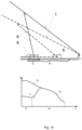
- FIG. 10 depicts a diagram of the aforementioned changes to friction between hinge elements in contact with each other and moving relative to each other during roof window closing for each embodiment.
- support with slider is in its end position, and the window is open.
- friction reduction means friction is T1
- T2' friction between slider with slide inserts and gutter bottom
- the roof window hinge is constructed out of intermediate arm 1, which, in the roof window tilt opening function, rises together with sash 2 relative to jamb 3.
- Intermediate arm 1 is mounted on both sides of the window to two sash side stiles 21.
- Intermediate arm 1 is attached via four-bar linkage 5 to gutter 4 mounted on jamb side stiles 31.
- Hinge gutter 4 features a sledge assembly in the form of slider 6 with spigot 61 for roof window sash lifting device spring assembly 5 coupling element 51.
- spring assembly 6 causes slider 5 to move along gutter 4 bottom.
- Front slide insert 71 and back slide insert 72 made out of plastic are located between gutter 4 and slider 6.
- the hinge also features support 8 between intermediate arm 1 and slider 6, so that during roof window opening support 8 rises together with sash 2 and its end rotatably attached to slider 6 moves together with it along the gutter 4.
- Roller 9 is located on support 8 spigot in gutter 4, which constitutes the friction reduction means between gutter 4 bottom and slider 6, so that friction between gutter 4 bottom and roller 9 along section S1 of the path is T1.
- the slider travels along path S which comprises sections S1 and S2. Whilst slider 6 is moving along section S1, roller 9 is in its contact function, where the roller exits gutter opening 41 to its bottom, along which it is guided, and rolling friction T1 occurs between gutter 4 bottom and slider 6. In that position slider 6 rises slightly relative to gutter 4 bottom.
- roller 9 In moving slider 6 from section S1 to section S2, the roller transitions to its contactless function, where roller 9 is positioned in slider opening 61 and gutter opening 41, and slider 6 back slide insert 72 is flush with gutter 4 bottom. Then slide friction T2 occurs between slider 6 and gutter 4 bottom.
- the roof window hinge differs from the hinge according to the second embodiment in that the friction reduction means constitutes roller assembly 10 in jamb side stile 31 aperture.
- the friction reduction means constitutes roller assembly 10 in jamb side stile 31 aperture.
- the slider travels along path S which comprises sections S1 and S2.
Landscapes
- Engineering & Computer Science (AREA)
- Mechanical Engineering (AREA)
- Architecture (AREA)
- Civil Engineering (AREA)
- Structural Engineering (AREA)
- Closing And Opening Devices For Wings, And Checks For Wings (AREA)
- Hinges (AREA)
- Wing Frames And Configurations (AREA)
Abstract
Description
- The object of the invention is a roof window hinge, especially for a window with evacuation properties and a roof window with that hinge.
- A solution entailing an intermediate arm unit in a dual-function roof window, featuring a sash lift support mechanism which works together with a set of springs positioned along jamb side stile was disclosed under patent
PL231796B1 - A roof window sash lifting device has been disclosed in application P.443602. It is constructed out of spring assembly with at least one main spring, and with at least one auxiliary spring unit seated in the device adjusting assembly, coupling assembly, sledge assembly, wherein the spring assembly is seated on at least one rod which at one end terminates with an adjustable plug abut with main spring of the spring assembly, and the other end of the said rod is rotatably attached to the coupling assembly, and the coupling assembly is designed for a detachable attachment to the device sledge assembly, and the coupling assembly includes a spring element for self-positioning of the coupling assembly to its coupled position with the sledge assembly.
- The force required to close a window in the disclosed solutions changes as the angle by which a roof window is open changes. The smaller the opening angle, the smaller the force required to close a window. The said force has to overcome, among others, friction occurring between the hinge gutter and its sledge assembly. The force required to close a window is at its maximum when the hinge support is in its end position, wherein the pressure exerted by the sash on the jamb side stile by the said support attains a value, which alters the current friction between the gutter and the sledge assembly to such an extent that it hinders easy roof window closing or the return of the support to a position where it is relatively parallel to the jamb side stile. The hinge according to claim 1 solves this problem by reducing friction between gutter bottom and sledge assembly using a friction reduction means during window closing, when the said friction in known disclosed solutions would reach a value hindering easy window closing or where the support is in its end position.
- The roof window hinge is constructed out of an intermediate arm, which, in the roof window tilt opening function, rises together with the sash relative to the jamb. The intermediate arm is mounted on both sides of the window to two sash side stiles. Whereas the intermediate arm is attached via a rotatable attachment to the gutter mounted on jamb side stiles. Preferably the rotatable attachment constitutes a four-bar linkage constructed out of a system of spigots by the jamb upper stile and a roof window sash. The hinge gutter comprises a sledge assembly in the form of a slider with a spigot for the roof window sash lifting device spring assembly coupling element. During roof window opening, pressure exerted by the spring assembly causes the slider to move along a gutter bottom. There is at least one slide insert made out of plastic between the gutter and the slider to help the slider move along the gutter bottom. Preferably it comprises a front slide insert and a back slide insert, wherein the names of the inserts indicate their position on the slider relative to the spring assembly. The front slide insert is located closer to the spring assembly than the back slide insert. The hinge also comprises a support between the intermediate arm and the slider, so that during roof window opening the slider rises together with the sash and its end rotatably attached to the slider moves together with it along the gutter. The slider moves together with the support along the gutter bottom along path S, which comprises two sections, S1 and S2. Friction T, comprising friction components T1 and T2, occurs between the slider with the slide inserts and the gutter bottom. Through a balancing of the forces exerted by the weight of the sash, which exerts pressure on the slider via the lifting arm, spring assembly tension, friction T between the slider and the sledge assembly gutter during roof window opening and closing, the sash, in all positions above the jamb, is held in a selected position. The essence of the invention entails reducing friction T2' between the gutter bottom and sledge assembly in solutions disclosed to date by using a friction reduction means, in particular during roof window closing when the support is in the aforementioned end position, and thus the slider and support are located along section S1 of path S.
- In the first embodiment, the friction reduction means comprises the gutter bottom fragment made out of a different material than the rest of the gutter, wherein that fragment is located along section S1 of path S taken by the slider along the gutter bottom. However, the material which the slider is made out of does not change. Because of the properties of the gutter bottom fragment along section S1 of the path, friction T1 occurs between the said fragment and slider, and in particular the slide insert, and it is less than friction T2' between these elements in the absence of friction reduction means. Friction reduction is achieved by changing the friction coefficient between the two materials of the gutter bottom and of the slider slide insert with inserts, which is smaller for these two along section S1 of path S and larger along section S2 of path S.
- In the second embodiment, the friction reduction means comprises a roller, or a bearing, or another element on the support spigot in the gutter. There are openings on the bottom of the slider and the gutter, preferably the gutter opening is longer than the slider opening. The friction reduction means remains in a contactless function along section S2 of path S, and is in a contact function along section S1 of path S. The transition process of the friction reduction means from the contactless function to the contact function during window opening may be described as follows: in the course of opening a window, as the sash tilt angle increases, the slider with the support and roller seated in the slider opening and partially in the gutter opening move along hinge gutter between sections S2 and S1. Along section S2 the roller is inactive, and sliding friction between the gutter bottom and the slider with slide inserts occurs with friction equal to T2. The roller becomes active once it exits the opening onto the hinge gutter bottom along section S1. Then the sliding friction between the gutter bottom and the slider with inserts changes to rolling friction between the roller and the gutter bottom. The roller rolling along the gutter bottom lifts the slider slightly relative to the gutter, and the friction T1 is generated between the gutter bottom and the roller. During window closing the above mentioned process is reversed. Friction reduction is achieved by changing the type of friction coefficient from sliding to rolling, so that the friction coefficient along section S1 is less than the friction coefficient along section S2 of path S.
- In the third embodiment, the friction reduction means along section S1 of the path, between gutter bottom and sledge assembly slider comprises at least one roller in a jamb side stile aperture, which rolls on the bottom of the aperture in jamb side stile or has its own axis of rotation. In this embodiment, the hinge gutter features a gutter opening, and the aperture on the bottom of the back slide insert is at least as wide as the gutter opening above the friction reduction means. The aperture in the back slide insert is above the friction reduction means which remains in a contactless function along section S2 of path S. Similar to the first embodiment, during window opening, the friction reduction means transitions from the contactless function to the contact function along section S1 of path S, wherein the back slide insert bottom is on the friction reduction means and friction changes from T2 along section S2 to T1. In the friction reduction means contactless function sliding friction occurs between
slider slide inserts back slide insert 72 androllers 10. Friction reduction is achieved by changing the type of friction coefficient from sliding to rolling, so that the friction coefficient along section S1 is less than the friction coefficient along section S2 of path S. The roof window hinge according to the invention, through the application of friction reduction means along section S1 of the slider path along gutter bottom, makes it possible to reduce friction T2' between gutter bottom and slider with slide inserts in disclosed inventions, which makes roof window closing considerably easier as the force required to overcome that friction and close a window is considerably lower. Friction changes along section S1 of slider path S along gutter bottom, where the support together with the slider is in its end position. In the support end position, the sash exerts the largest pressure on jamb side stile through the support, and friction without the friction reduction means is T2', therefore use of this means in the end position of the support with slider is preferable. - The illustration depicts the invention, with given figures depicting the following:
-
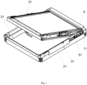
Fig. 1 roof window and hinge -
Fig. 2 hinge according to the first embodiment -
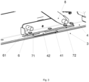
Fig. 3 part of slider and gutter with a fragment of gutter bottom made out of a material which functions as a friction reduction means -
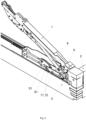
Fig. 4 rear view of the hinge according to the second embodiment -
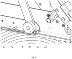
Fig. 5 hinge fragment with a roller according to the second embodiment -
Fig. 6 aperture in the jamb and hinge with friction reduction means and slider back slide insert according to the third embodiment -
Fig. 7 bottom view of the slider with back and front slide inserts according to the third embodiment -
Fig. 8 longitudinal section of the roller assembly according to the third embodiment -
Fig. 9 hinge fragment with a roller assembly according to the third embodiment -
Fig. 10 diagram of hinge operation during window closing and friction graph for given path S sections - In the first embodiment, the roof window hinge is constructed out of
intermediate arm 1, which, in the roof window tilt opening function, rises together withsash 2 relative tojamb 3.Intermediate arm 1 is mounted on both sides of the window to twosash side stiles 21.Intermediate arm 1 is attached via four-bar linkage 11 togutter 4 mounted onjamb side stiles 31. Hingegutter 4 features a sledge assembly in the form ofslider 6 withspigot 61 for roof window sash liftingdevice spring assembly 5coupling element 51. During roof window opening, pressure exerted byspring assembly 6 causesslider 5 to move alonggutter 4 bottom. Front slide insert 71 andback slide insert 72 made out of plastic are located betweengutter 4 andslider 6. The hinge also featuressupport 8 betweenintermediate arm 1 andslider 6, so that during roofwindow opening slider 8 rises together withsash 2 and its end rotatably attached toslider 6 moves together with it along thegutter 4. Duringwindow closing slider 6 travels along path S which comprises at least two sections S1 and S2. While the slider is moving along path S1,support 8 reaches its end position, for which the force required to close the window increases considerably. In the first embodiment a friction reduction means was used, so as to make it easier forsupport 8 to travel from its end position in the direction of section S2 of the path. The friction reduction means is a material used to makegutter bottom fragment 42 that is different than the material used to make the remaining part of the gutter. Whensupport 8 is in the aforementioned end position along section S1 of the path, then the said fragment is in contact withslider 6, and in particular with slide inserts 71 and 72. Friction T1 occurs between the saidgutter 4 material andslider 6 slide inserts.Fig. 10 depicts a diagram of the aforementioned changes to friction between hinge elements in contact with each other and moving relative to each other during roof window closing for each embodiment. Along section S1 of the path, support with slider is in its end position, and the window is open. Through the action of the friction reduction means, friction is T1, whereas in a solution without the friction reduction means friction would be T2'. Once the slider moves to section S2 of path S, the friction reduction means is no longer engaged, and friction between slider with slide inserts and gutter bottom is T2. - In the second embodiment, the roof window hinge is constructed out of
intermediate arm 1, which, in the roof window tilt opening function, rises together withsash 2 relative to jamb 3.Intermediate arm 1 is mounted on both sides of the window to twosash side stiles 21.Intermediate arm 1 is attached via four-bar linkage 5 togutter 4 mounted onjamb side stiles 31.Hinge gutter 4 features a sledge assembly in the form ofslider 6 withspigot 61 for roof window sash liftingdevice spring assembly 5coupling element 51. During roof window opening, pressure exerted byspring assembly 6 causesslider 5 to move alonggutter 4 bottom.Front slide insert 71 and back slideinsert 72 made out of plastic are located betweengutter 4 andslider 6. The hinge also featuressupport 8 betweenintermediate arm 1 andslider 6, so that during roofwindow opening support 8 rises together withsash 2 and its end rotatably attached toslider 6 moves together with it along thegutter 4.Roller 9 is located onsupport 8 spigot ingutter 4, which constitutes the friction reduction means betweengutter 4 bottom andslider 6, so that friction betweengutter 4 bottom androller 9 along section S1 of the path is T1. During roof window closing, the slider travels along path S which comprises sections S1 and S2. Whilstslider 6 is moving along section S1,roller 9 is in its contact function, where the roller exits gutter opening 41 to its bottom, along which it is guided, and rolling friction T1 occurs betweengutter 4 bottom andslider 6. In thatposition slider 6 rises slightly relative togutter 4 bottom. In movingslider 6 from section S1 to section S2, the roller transitions to its contactless function, whereroller 9 is positioned inslider opening 61 andgutter opening 41, andslider 6back slide insert 72 is flush withgutter 4 bottom. Then slide friction T2 occurs betweenslider 6 andgutter 4 bottom. - In the third embodiment, the roof window hinge differs from the hinge according to the second embodiment in that the friction reduction means constitutes
roller assembly 10 injamb side stile 31 aperture. On the bottom ofback slide insert 72 there is an aperture limited byarms gutter 4 bottom. During roof window closing, the slider travels along path S which comprises sections S1 and S2. Whenslider 6 is moving along section S1,roller assembly 10 is in its contact function, where back slideinsert bottom 723 is aboveroller assembly 10, andslider 6 is slightly raised relative togutter 4 bottom. Then rolling friction T1 occurs between backslide insert bottom 723 androller assembly 10. In movingslider 6 from section S1 to section S2, back slideinsert bottom 723 is also moved, so that its aperture is aboveroller assembly 10, androller assembly 10 is in its contactless function. Whereasslider 6 is in contact withgutter 4 bottom via slide inserts 71, 72 and friction T2 occurs between them.
Claims (18)
- Roof window hinge comprising following elements:- an intermediate arm (1), rotatably attached to a gutter (4), wherein the gutter (4) is designed for mounting on window jamb side stile (31),- a sledge assembly (6) and- a support (8), wherein the support (8) is rotatably attached to a intermediate arm spigots, and to the sledge assembly (6),- wherein the support (8) with the sledge assembly (6) assume end positions along section (S1) of path (S) of the sledge assembly along the gutter (4)characterized in that it comprises a friction reduction means (9, 10) between sledge assembly (6) and the gutter bottom along section (S1) of path (S).
- The hinge according to claim 1 characterized in that the sledge assembly (6) comprising a slider, designed to move along path S on the gutter (4) bottom, wherein there is at least one slide insert (71, 72) between slider (6) and gutter (4) bottom.
- The hinge according to claim 1 or 2 characterized in that the friction reduction means comprising a material, which at least one gutter bottom fragment (42) is made of, and the said fragment is in contact with slider (6) with slide inserts (71, 72), when the support is in its end position along section S1.
- The hinge according to claim 1 or 2 characterized in that the friction reduction means operates in two functions, where one is referred to as the contactless function where the friction reduction means (9) is inactive and the support (8) with sledge assembly (6) is on section (S2) of path (S) and the sliding friction occurs between the gutter (4) bottom and slider (6) with slide inserts (71, 72), and the other function referred to as the contact function, where the friction reduction means (9) is active, and support (8) with slider (6) is on section (S1) of path (S) and rolling friction (T1) occurs between gutter (4) bottom and the friction reduction means (9).
- The hinge according to claim 1 or 2, or 4 characterized in that the gutter bottom comprises a gutter opening (41), and the slider bottom comprises a slider opening (61), for the friction reduction means (9) in its contactless function, where sledge assembly slider (6) is in contact with hinge gutter (4) bottom via slide inserts (71, 72).
- The hinge according to claim 1 or 2, or 4 characterized in that in the contact function, the friction reduction means (9) is outside of gutter opening (41) and is in contact with the gutter (4) bottom.
- The hinge according to claim 1 or 2, or 4, or 5, or 6 characterized in that the friction reduction means is a roller (9) on support (8) spigot in the hinge gutter.
- The hinge according to claim 1 or 2, or 4, or 5, or 6 characterized in that the friction reduction means is a rolling-element bearing on support spigot in hinge gutter.
- The hinge according to claim 1 or 2 characterized in that the friction reduction means operates in two functions, where one is referred to as the contactless function where friction reduction means (10) is inactive and support (8) with sledge assembly (6) is on section (S2) of path (S) and sliding friction occurs between gutter (4) bottom and slider (4) with slide inserts (71, 72), and the other function referred to as the contact function, where friction reduction means (10) is active, and the support (8) with slider (6) is on section (S1) of path (S) and rolling friction (T1) occurs between back slide insert (72) and the friction reduction means (9).
- The hinge according to claim 1 or 2, or 9 characterized in that the gutter comprises gutter opening (41), and jamb side stile (31) features aperture (311), with friction reduction means (10) in the said aperture between gutter (4) bottom and slider (6).
- The hinge according to claim 1 or 2, or 9, or 10 characterized in that back slide insert (72) bottom features an aperture limited by arms (721, 722), and the aperture is at least as wide as gutter opening (41) located above friction reduction means (10) in the contactless function of that means.
- The hinge according to claim 1 or 2, or 9, or 10, or 11 characterized in that in the friction reduction means (10) contact function, back slide insert bottom (723) is on the friction reduction means.
- The hinge according to claim 1 or 2, or 9, or 10, or 11 characterized in that the friction reduction means constitutes at least one roller.
- The hinge according to claim 13 characterized in that the roller rolls on the bottom of the aperture in jamb side stile (31).
- The hinge according to claim 13 characterized in that the roller features its own axis of rotation.
- The hinge according to claim 1 or 2, or 3, or 4, or 5, or 6, or 7, or 8, or 9, or 10, or 11, or 12, or 13, or 14, or 15 characterized in that intermediate arm (1) is attached to gutter (4) using a four-bar linkage.
- Roof window constructed out of a jamb and a sash characterized in that sash (2) is suspended from jamb (3) using a hinge according to claims 1-16.
- Roof window according to claim 17 characterized in that sledge assembly (6) features spigot (61) attached via coupling element (51) to roof window sash lifting device spring assembly (5).
Applications Claiming Priority (1)
| Application Number | Priority Date | Filing Date | Title |
|---|---|---|---|
| PL444145A PL444145A1 (en) | 2023-03-21 | 2023-03-21 | Roof window hinge and roof window with this hinge |
Publications (3)
| Publication Number | Publication Date |
|---|---|
| EP4435216A1 true EP4435216A1 (en) | 2024-09-25 |
| EP4435216B1 EP4435216B1 (en) | 2026-03-04 |
| EP4435216C0 EP4435216C0 (en) | 2026-03-04 |
Family
ID=90366489
Family Applications (1)
| Application Number | Title | Priority Date | Filing Date |
|---|---|---|---|
| EP24164152.1A Active EP4435216B1 (en) | 2023-03-21 | 2024-03-18 | Roof window hinge and a roof window with that hinge |
Country Status (2)
| Country | Link |
|---|---|
| EP (1) | EP4435216B1 (en) |
| PL (1) | PL444145A1 (en) |
Cited By (1)
| Publication number | Priority date | Publication date | Assignee | Title |
|---|---|---|---|---|
| DK202470168A1 (en) * | 2024-06-18 | 2026-01-08 | Vkr Holding As | Roof window with a lifting device with a selective top bearing fitting |
Citations (4)
| Publication number | Priority date | Publication date | Assignee | Title |
|---|---|---|---|---|
| FR2506823A1 (en) * | 1981-05-29 | 1982-12-03 | Frank Gmbh Wilh | VASISTAS FOR ROOFING |
| US20110107678A1 (en) * | 2009-09-28 | 2011-05-12 | Bauman Leonard P | Concealed casement window hinge with roller and integral shipping block |
| EP1520951B1 (en) * | 2003-10-03 | 2012-12-26 | VKR Holding A/S | A sliding device, a window having such a sliding device and a method for mounting a sash in such a window |
| EP3348763A1 (en) * | 2017-01-16 | 2018-07-18 | FAKRO PP Sp. z o.o. | Intermediate arm assembly for a dual-function roof window |
-
2023
- 2023-03-21 PL PL444145A patent/PL444145A1/en unknown
-
2024
- 2024-03-18 EP EP24164152.1A patent/EP4435216B1/en active Active
Patent Citations (5)
| Publication number | Priority date | Publication date | Assignee | Title |
|---|---|---|---|---|
| FR2506823A1 (en) * | 1981-05-29 | 1982-12-03 | Frank Gmbh Wilh | VASISTAS FOR ROOFING |
| EP1520951B1 (en) * | 2003-10-03 | 2012-12-26 | VKR Holding A/S | A sliding device, a window having such a sliding device and a method for mounting a sash in such a window |
| US20110107678A1 (en) * | 2009-09-28 | 2011-05-12 | Bauman Leonard P | Concealed casement window hinge with roller and integral shipping block |
| EP3348763A1 (en) * | 2017-01-16 | 2018-07-18 | FAKRO PP Sp. z o.o. | Intermediate arm assembly for a dual-function roof window |
| PL231796B1 (en) | 2017-01-16 | 2019-04-30 | Fakro Pp Spolka Z Ograniczona Odpowiedzialnoscia | Intermediate arm assembly in a bifunctional roof window |
Cited By (1)
| Publication number | Priority date | Publication date | Assignee | Title |
|---|---|---|---|---|
| DK202470168A1 (en) * | 2024-06-18 | 2026-01-08 | Vkr Holding As | Roof window with a lifting device with a selective top bearing fitting |
Also Published As
| Publication number | Publication date |
|---|---|
| EP4435216B1 (en) | 2026-03-04 |
| PL444145A1 (en) | 2024-09-23 |
| EP4435216C0 (en) | 2026-03-04 |
Similar Documents
| Publication | Publication Date | Title |
|---|---|---|
| US4420905A (en) | Closure hardware | |
| EP4435216A1 (en) | Roof window hinge and a roof window with that hinge | |
| DK180044B1 (en) | Roof window with improved coupling mechanism, method for installing the roof window including coupling a secondary frame to a primary frame and method for dismantling the same. | |
| EP0113559B1 (en) | A window stay | |
| EP1553253A1 (en) | Egress hinge | |
| US5568703A (en) | Roof window | |
| CN103717822A (en) | Lifting door having a movable door leaf guide | |
| EP1873323A1 (en) | A lifting device and a window comprising such a lifting device | |
| GB2278882A (en) | Concealed door closer | |
| WO1999061739A2 (en) | Window and door closing mechanism | |
| JPS6147268B2 (en) | ||
| AU2018203798B1 (en) | A window stay | |
| EP0648308A1 (en) | Track system for sectional doors | |
| EP3042017B1 (en) | Weathertight window or door having at least one sliding wing | |
| CA2434348A1 (en) | Automatic door sweep | |
| GB2225378A (en) | Improvements in friction stay hinges | |
| EP0081333B1 (en) | A window, especially for installation in an inclined roof | |
| FI82526C (en) | UTSTAELLNINGSANORDNING FOER FLYGELDELEN AV ETT FOENSTER, EN DOERR ELLER MOTSVARANDE. | |
| CN107060542A (en) | A kind of sliding block and slide support hinge of window slide support hinge | |
| CN102421974B (en) | Fittings between leaf and fixed frame of window or door | |
| DK3064698T3 (en) | gate | |
| CN100569623C (en) | elevator door device | |
| CN108699876B (en) | Lining plate arrangement with frame-side adjusting elements | |
| GB2228530A (en) | Friction stay-hinge | |
| KR20050035068A (en) | Fitting for lift-sliding doors or windows and runner of such a fitting |
Legal Events
| Date | Code | Title | Description |
|---|---|---|---|
| PUAI | Public reference made under article 153(3) epc to a published international application that has entered the european phase |
Free format text: ORIGINAL CODE: 0009012 |
|
| STAA | Information on the status of an ep patent application or granted ep patent |
Free format text: STATUS: THE APPLICATION HAS BEEN PUBLISHED |
|
| AK | Designated contracting states |
Kind code of ref document: A1 Designated state(s): AL AT BE BG CH CY CZ DE DK EE ES FI FR GB GR HR HU IE IS IT LI LT LU LV MC ME MK MT NL NO PL PT RO RS SE SI SK SM TR |
|
| STAA | Information on the status of an ep patent application or granted ep patent |
Free format text: STATUS: REQUEST FOR EXAMINATION WAS MADE |
|
| 17P | Request for examination filed |
Effective date: 20250114 |
|
| STAA | Information on the status of an ep patent application or granted ep patent |
Free format text: STATUS: EXAMINATION IS IN PROGRESS |
|
| 17Q | First examination report despatched |
Effective date: 20250312 |
|
| GRAP | Despatch of communication of intention to grant a patent |
Free format text: ORIGINAL CODE: EPIDOSNIGR1 |
|
| STAA | Information on the status of an ep patent application or granted ep patent |
Free format text: STATUS: GRANT OF PATENT IS INTENDED |
|
| INTG | Intention to grant announced |
Effective date: 20251029 |
|
| GRAS | Grant fee paid |
Free format text: ORIGINAL CODE: EPIDOSNIGR3 |
|
| GRAA | (expected) grant |
Free format text: ORIGINAL CODE: 0009210 |
|
| STAA | Information on the status of an ep patent application or granted ep patent |
Free format text: STATUS: THE PATENT HAS BEEN GRANTED |
|
| AK | Designated contracting states |
Kind code of ref document: B1 Designated state(s): AL AT BE BG CH CY CZ DE DK EE ES FI FR GB GR HR HU IE IS IT LI LT LU LV MC ME MK MT NL NO PL PT RO RS SE SI SK SM TR |
|
| REG | Reference to a national code |
Ref country code: CH Ref legal event code: F10 Free format text: ST27 STATUS EVENT CODE: U-0-0-F10-F00 (AS PROVIDED BY THE NATIONAL OFFICE) Effective date: 20260304 Ref country code: GB Ref legal event code: FG4D |
|
| REG | Reference to a national code |
Ref country code: IE Ref legal event code: FG4D |
|
| REG | Reference to a national code |
Ref country code: DE Ref legal event code: R096 Ref document number: 602024002895 Country of ref document: DE |
|
| U01 | Request for unitary effect filed |
Effective date: 20260304 |
|
| PGFP | Annual fee paid to national office [announced via postgrant information from national office to epo] |
Ref country code: AT Payment date: 20260303 Year of fee payment: 3 |
|
| U07 | Unitary effect registered |
Designated state(s): AT BE BG DE DK EE FI FR IT LT LU LV MT NL PT RO SE SI Effective date: 20260311 |