EP4434919A1 - X-ray inspection apparatus - Google Patents
X-ray inspection apparatus Download PDFInfo
- Publication number
- EP4434919A1 EP4434919A1 EP24163950.9A EP24163950A EP4434919A1 EP 4434919 A1 EP4434919 A1 EP 4434919A1 EP 24163950 A EP24163950 A EP 24163950A EP 4434919 A1 EP4434919 A1 EP 4434919A1
- Authority
- EP
- European Patent Office
- Prior art keywords
- unit
- conveying
- swing member
- ray
- inspection apparatus
- Prior art date
- Legal status (The legal status is an assumption and is not a legal conclusion. Google has not performed a legal analysis and makes no representation as to the accuracy of the status listed.)
- Pending
Links
Images


Classifications
-
- G—PHYSICS
- G01—MEASURING; TESTING
- G01N—INVESTIGATING OR ANALYSING MATERIALS BY DETERMINING THEIR CHEMICAL OR PHYSICAL PROPERTIES
- G01N23/00—Investigating or analysing materials by the use of wave or particle radiation, e.g. X-rays or neutrons, not covered by groups G01N3/00 – G01N17/00, G01N21/00 or G01N22/00
- G01N23/02—Investigating or analysing materials by the use of wave or particle radiation, e.g. X-rays or neutrons, not covered by groups G01N3/00 – G01N17/00, G01N21/00 or G01N22/00 by transmitting the radiation through the material
- G01N23/04—Investigating or analysing materials by the use of wave or particle radiation, e.g. X-rays or neutrons, not covered by groups G01N3/00 – G01N17/00, G01N21/00 or G01N22/00 by transmitting the radiation through the material and forming images of the material
-
- G—PHYSICS
- G01—MEASURING; TESTING
- G01N—INVESTIGATING OR ANALYSING MATERIALS BY DETERMINING THEIR CHEMICAL OR PHYSICAL PROPERTIES
- G01N2223/00—Investigating materials by wave or particle radiation
- G01N2223/30—Accessories, mechanical or electrical features
- G01N2223/304—Accessories, mechanical or electrical features electric circuits, signal processing
-
- G—PHYSICS
- G01—MEASURING; TESTING
- G01N—INVESTIGATING OR ANALYSING MATERIALS BY DETERMINING THEIR CHEMICAL OR PHYSICAL PROPERTIES
- G01N2223/00—Investigating materials by wave or particle radiation
- G01N2223/30—Accessories, mechanical or electrical features
- G01N2223/33—Accessories, mechanical or electrical features scanning, i.e. relative motion for measurement of successive object-parts
- G01N2223/3308—Accessories, mechanical or electrical features scanning, i.e. relative motion for measurement of successive object-parts object translates
-
- G—PHYSICS
- G01—MEASURING; TESTING
- G01N—INVESTIGATING OR ANALYSING MATERIALS BY DETERMINING THEIR CHEMICAL OR PHYSICAL PROPERTIES
- G01N2223/00—Investigating materials by wave or particle radiation
- G01N2223/60—Specific applications or type of materials
- G01N2223/643—Specific applications or type of materials object on conveyor
Definitions
- the present disclosure relates to an X-ray inspection apparatus.
- Patent Literature 1 Japanese Unexamined Patent Publication No. 2018-155561
- an X-ray inspection apparatus having a pair of conveying units arranged side by side with an X-ray passing region interposed therebetween is known.
- an X-ray irradiation unit is provided on one (an upper one) of the pair of conveying units
- an X-ray detection unit is provided on the other (a lower one) of the pair of conveying units.
- An X-ray emitted from the X-ray irradiation unit passes through an article, passes through the X-ray passing region, and enters the X-ray detection unit.
- the X-ray is converted into light and further converted into an electric signal, and an X-ray transmission image is generated in a control unit.
- Both the conveying units are provided with an X-ray shielding member that shields the X-ray at an end of the X-ray passing region. With this configuration, it is possible to determine whether each of the pair of conveying units is attached based on the X-ray transmission image.
- An object of the present disclosure is to provide an X-ray inspection apparatus capable of determining attachment of the pair of conveying units with only one sensor unit.
- attachment of the pair of conveying units can be determined only by one sensor unit.
- an X-ray inspection apparatus 1 includes an apparatus body 2, support legs 3, a shield box (housing) 4, a conveying unit 5, an X-ray irradiation unit 6, an X-ray detection unit 7, a display operation unit (a notification unit) 8, and a control unit 10.
- the X-ray inspection apparatus 1 generates an X-ray transmission image of an article G while conveying the article G, and inspects the article G based on the X-ray transmission image (for example, storage number inspection, foreign matter mixing inspection, missing inspection, crack and chip inspection, and the like).
- the article G before the inspection is carried into the X-ray inspection apparatus 1 by a carry-in conveyor 20a.
- the article G after the inspection is carried out from the X-ray inspection apparatus 1 by a carry-out conveyor 30a.
- the article G determined as a defective product by the X-ray inspection apparatus 1 is distributed to an outside of a production line by a distribution device (not illustrated) disposed downstream of the carry-out conveyor 30a.
- the article G determined as a non-defective product by the X-ray inspection apparatus 1 passes through the distribution device as it is.
- the apparatus body 2 houses the control unit 10 and the like.
- the support legs 3 support the apparatus body 2.
- the shield box 4 is provided in the apparatus body 2.
- the shield box 4 prevents leakage of X-rays to the outside.
- An inspection region R in which the article G is inspected by the X-ray is provided inside the shield box 4.
- a carry-in port 4a and a carry-out port 4b are formed in the shield box 4.
- the article G before inspection is carried into the inspection region R from the carry-in conveyor 20a through the carry-in port 4a.
- the article G after inspection is carried out from the inspection region R to the carry-out conveyor 30a via the carry-out port 4b.
- Each of the carry-in port 4a and the carry-out port 4b is provided with an X-ray shielding curtain (not illustrated) that prevents leakage of X-rays.
- the conveying unit 5 is disposed in the shield box 4.
- the conveying unit 5 conveys the article G from the carry-in port 4a to the carry-out port 4b via the inspection region R in a conveying direction A.
- the conveying unit 5 is, for example, a belt conveyor stretched between the carry-in port 4a and the carry-out port 4b.
- the apparatus body 2 has, for example, a housing 9 made of a material capable of shielding electromagnetic waves such as X-rays.
- the housing 9 includes an upper portion 9a provided with the display operation unit 8 on a front surface thereof, a back portion 9b extending in a vertical direction, and a lower portion 9c protruding forward from the back portion 9b.
- a first wall portion 91 of the upper portion 9a, a second wall portion 92 of the back portion 9b, and a third wall portion 93 of the lower portion 9c form a U-shape opened forward (see FIG.
- a front surface of the shield box 4 is covered with a shielding cover 4c that is opened and closed at the time of maintenance or the like.
- the X-ray irradiation unit 6 is disposed, for example, in the upper portion 9a of the housing 9.
- the X-ray irradiation unit 6 irradiates the article G conveyed by the conveying unit 5 with the X-ray (electromagnetic wave).
- the X-ray irradiation unit 6 includes, for example, an X-ray tube that emits the X-ray, and a collimator that spreads the X-ray emitted from the X-ray tube in a fan shape in a plane perpendicular to the conveying direction A.
- the X-ray detection unit 7 is disposed in the lower portion 9c of the housing 9.
- the X-ray detection unit 7 detects the X-ray emitted by the X-ray irradiation unit 6 and transmitted through the article G.
- the X-ray detection unit 7 is configured as, for example, a line sensor.
- the X-ray detection unit 7 includes a plurality of photodiodes arranged one-dimensionally in a horizontal direction perpendicular to the conveying direction A, and a scintillator disposed on the X-ray incident side with respect to each photodiode. In this case, in the X-ray detection unit 7, the X-ray incident on the scintillator is converted into light, and the light incident on each photodiode is converted into an electric signal.
- the display operation unit 8 is provided in the upper portion 9a of the housing 9 and faces forward.
- the display operation unit 8 displays various types of information (that is, notifies an operator of an operation state) and receives inputs of various conditions.
- the display operation unit 8 is, for example, a liquid crystal display, and displays an operation screen as a touch panel. In this case, the operator can input various conditions via the display operation unit 8.
- the display operation unit 8 provides notification of various abnormalities in the X-ray inspection apparatus 1.
- a notification lamp 11 also functioning as the notification unit is erected on the upper portion 9a of the housing 9.
- the control unit 10 is disposed in the apparatus body 2.
- the control unit 10 controls an operation of each unit of the X-ray inspection apparatus 1.
- the control unit 10 includes a central processing unit (CPU), a read only memory (ROM), a random access memory (RAM), and the like.
- the control unit 10 receives an A/D converted signal output from the X-ray detection unit 7.
- the control unit 10 functions as an inspection unit that generates the X-ray transmission image of the article G based on the signal output from the X-ray detection unit 7 and inspects the article G based on the X-ray transmission image.
- the conveying unit 5 includes a pair of conveying units 20 and 30 and an X-ray shielding unit 40.
- the pair of conveying units 20 and 30 are arranged side by side with the passing region X of the X-ray (see FIG. 1 ) from the X-ray irradiation unit 6 to the X-ray detection unit 7 interposed therebetween.
- the passing region X extends in a direction B.
- the direction B is a third direction intersecting both a first direction (that is, the conveying direction A) in which the conveying unit 5 conveys the article and a second direction (see FIG. 1 ) in which the X-ray irradiation unit 6 and the X-ray detection unit 7 face each other.
- the conveying unit 20 disposed upstream in the conveying direction A includes a frame 21, a plurality of conveying rollers 22 and 23, and a conveying belt 24.
- the frame 21 is attached to the apparatus body 2 (shield box 4) via a motor box 26.
- the conveying rollers 22 and 23 are rotatably supported by the frame 21.
- the conveying roller 23 disposed upstream in the conveying direction A is a driving roller
- the conveying roller 22 disposed downstream in the conveying direction A is a driven roller.
- the conveying belt 24 is an endless belt, and is stretched between the conveying rollers 22 and 23. In a state where the conveying unit 20 is attached to the apparatus body 2, a part of the frame 21 is engaged with and fixed to a part of the shield box 4.
- the frame 21 and a conveying surface 24a of the conveying belt 24 extend parallel (horizontally) to the conveying direction A.
- the conveying unit 30 disposed downstream in the conveying direction A includes a frame 31, a plurality of conveying rollers 32 and 33, and a conveying belt 34.
- the frame 31 is attached to the apparatus body 2 (shield box 4) via a motor box 36.
- the conveying rollers 32 and 33 are rotatably supported by the frame 31.
- the conveying roller 32 disposed downstream in the conveying direction A is a driving roller
- the conveying roller 33 disposed upstream in the conveying direction A is a driven roller.
- the conveying belt 34 is an endless belt, and is stretched between the conveying rollers 32 and 33. In a state where the conveying unit 30 is attached to the apparatus body 2, a part of the frame 31 is engaged with and fixed to a part of the shield box 4.
- the frame 31 and a conveying surface 34a of the conveying belt 34 extend parallel (horizontally) to the conveying direction A.
- the X-ray inspection apparatus 1 includes a determination unit 15 that determines attachment of the conveying unit 20 and the conveying unit 30.
- the determination unit 15 determines attachment of both the conveying unit 20 and the conveying unit 30 without depending on the X-ray transmission image (without irradiating the X-ray from the X-ray irradiation unit 6).
- the determination unit 15 will be described with reference to FIGS. 3 to 6 .
- FIG. 5 is a perspective view illustrating a support portion and a swing member attached to the conveying unit 20 and the conveying unit 30.
- FIG. 6 is a perspective view illustrating the support portion and the swing member as viewed from a back surface side.
- the determination unit 15 includes a stopper 60 attached to the conveying unit 20 and an actuator 70 attached to the conveying unit 30.
- a swing member 74 of the actuator 70 is present at a contact stop position (a predetermined position) P1 in a state where at least a part of the actuator 70 is in contact with the stopper 60.
- the determination unit 15 includes a magnetic proximity switch (a sensor unit) 80 that detects the actuator 70 present at the contact stop position P1.
- the stopper 60 and the actuator 70 are arranged between the conveying surface 24a of the conveying unit 20 and the conveying surface 34a of the conveying unit 30, and a second wall portion 92 extending in the vertical direction on sides of the conveying surfaces 24a and 34a.
- An installation space of the stopper 60 and the actuator 70 is set in a region that is not originally used for conveyance by the conveying unit 5.
- the magnetic proximity switch 80 is disposed on an inner surface side of the second wall portion 92, that is, in the back portion 9b.
- the magnetic proximity switch 80 is fixed to the second wall portion 92 by a special screw 81 so as not to be removed by a general-purpose tool in order to prevent invalidation of an interlock.
- the second wall portion 92 extends between the stopper 60 and the actuator 70, and the magnetic proximity switch 80.
- the magnetic proximity switch 80 detects the presence of the swing member 74 in a non-contact manner.
- the magnetic proximity switch 80 can communicate information with the control unit 10, and transmits information indicating the presence or absence of the swing member 74 to the control unit 10. Such communication means may be provided separately from the magnetic proximity switch 80.
- the stopper 60 is fixed to the frame 21 of the conveying unit 20 and extends downstream in the conveying direction A (toward the conveying unit 30).
- the actuator 70 is fixed to the frame 31 of the conveying unit 30 and extends upstream in the conveying direction A (toward the conveying unit 20).
- Each of the conveying unit 20 and the conveying unit 30 is detachable from the apparatus body 2 when the operation of the X-ray inspection apparatus 1 is stopped.
- the conveying unit 20 is rotated as a whole about a pin 27 attached to the frame 21, as the operator lifts a portion near the conveying roller 22 by hand.
- the conveying unit 30 is rotated as a whole about a pin 37 attached to the frame 31, as the operator lifts a portion near the conveying roller 33 by hand. Both a rotation axis L2 passing through the pin 27 and a rotation axis L3 passing through the pin 37 extend parallel to the direction B.
- the conveying unit 20 and the conveying unit 30 are separated from the apparatus body 2 (shield box 4) by being respectively detached from the motor box 26 and the motor box 36 after rotation.
- the stopper 60 is integrated with the frame 21, it is removed together with the conveying unit 20.
- the actuator 70 is integrated with the frame 31, it is removed together with the conveying unit 30.
- the stopper 60 includes a base plate 61 fixed to the frame 21 and a support base (support portion) 62 provided at a tip of the base plate 61 and extending, for example, flatly.
- An upper surface of the support base 62 is, for example, parallel to the conveying surface 24a of the conveying belt 24.
- the actuator 70 includes a base portion 71 fixed to the frame 31, a support shaft 72 supported by a pair of support plate portions 71a of the base portion 71, and an arm member 73 and a swing member 74 swingably supported by the support shaft 72.
- the support shaft 72 is, for example, parallel to the conveying surface 34a of the conveying belt 34.
- the support shaft 72 includes a small diameter shaft portion 72a provided at an upstream portion thereof in the conveying direction A.
- the arm member 73 includes a pair of triangular arm portions 73a swingably supported by the small diameter shaft portion 72a and a bottom plate portion 73c provided at a tip of the arm portion 73a.
- the swing member 74 includes a holding portion 76 to which the bottom plate portion 73c is fixed and a magnet 77 held by the holding portion 76.
- the stopper 60 is manufactured by, for example, bending a plate material made of metal.
- the actuator 70, except for the magnet 77, is manufactured by, for example, bending a plate material made of metal. An outer surface of the magnet 77 located farther from the support shaft 72 is not covered by the holding portion 76 and is exposed to the outside.
- the magnet 77 is, for example, a block-shaped permanent magnet.
- the swing member 74 including the holding portion 76 and the magnet 77 integrated together swings in a predetermined range around the support shaft 72.
- the arm portion 73a includes a base end portion 73b having an acute angle shape on the opposite side of the swing member 74 with respect to the support shaft 72.
- the conveying unit 30 is provided with a restriction mechanism 70X that restricts a swing range of the swing member 74.
- the support base 62 of the stopper 60 and the swing member 74 of the actuator 70 are located between the conveying unit 20 and the conveying unit 30 in the conveying direction A.
- the support base 62 and the swing member 74 are located at positions where at least a part thereof overlaps with each other in plan view.
- a position where the support base 62 and the swing member 74 overlap is a contact position in the determination unit 15. If the conveying unit 20 is not attached but the conveying unit 30 is attached, the support base 62 is not present at the contact position.
- the arm member 73 and the swing member 74 hang down by their own weight and are located at a natural hanging position P2 (see FIG. 7B ).
- the natural hanging position P2 is within a swing range of the arm member 73 described above.
- the magnetic proximity switch 80 detects that the swing member 74 is present at the contact stop position P1 in a state where the swing member 74 is in contact with the support base 62 (in the present embodiment, the holding portion 76 is placed on the support base 62).
- a sensor surface of the magnetic proximity switch 80 is parallel to the outer surface of the magnet 77.
- the magnetic proximity switch 80 approaches the contact stop position P1.
- the contact stop position P1 is equal to the contact position described above.
- the contact position that is, a position of a top surface of support base 62 is located closer to the magnetic proximity switch 80 than immediately below the support shaft 72 (or the support plate portion 71a). As illustrated in FIG.
- the magnetic proximity switch 80 detects that the swing member 74 is not present at the contact stop position P1. That is, the magnet 77 present at the contact stop position P1 turns on the magnetic proximity switch 80, and the magnet 77 present at the natural hanging position P2 turns off the magnetic proximity switch 80.
- the natural hanging position P2 is located immediately below the support shaft 72 (or the support plate portion 71 a), and thus is farther from the magnetic proximity switch 80 than the contact stop position P1.
- the determination unit 15 is an interlock switch mechanism that detects that two conveyors are appropriately installed.
- the control unit 10 determines whether both of the conveying units 20 and 30 are attached on the basis of the detection result of the magnetic proximity switch 80.
- the control unit 10 can determine that both of the conveying units 20 and 30 are not attached. Further, in a case where the conveying unit 30 is attached and the conveying unit 20 is not attached, since the swing member 74 is located at the natural hanging position P2, the control unit 10 can determine that both of the conveying units 20 and 30 are not attached.
- the operator first attaches the conveying unit 20 and subsequently attaches the conveying unit 30.
- the actuator 70 approaches the stopper 60 from above, and the holding portion 76 is placed on the support base 62.
- the control unit 10 can determine that both of the conveying units 20 and 30 are attached. Note that in a case where the conveying unit 30 is attached first, since the presence of the actuator 70 prevents the stopper 60 from descending, it is physically impossible to attach the conveying unit 20. Therefore, also in this case, the swing member 74 is located at the natural hanging position P2, and the control unit 10 can determine that both of the conveying units 20 and 30 are not attached.
- the control unit 10 When determining that both of the pair of conveying units 20 and 30 are not attached, the control unit 10 stops X-ray irradiation by the X-ray irradiation unit 6. Further, the control unit 10 controls the display operation unit 8 to display a result of determination described above. The control unit 10 controls the notification lamp 11 to provide notification of the result of the determination described above.
- the magnetic proximity switch 80 detects that the swing member 74 is present at the predetermined position. Therefore, attachment of the pair of conveying units 20 and 30 can be determined only by one magnetic proximity switch 80.
- a position of the swing member 74 can be detected in a non-contact manner by detection of the magnet 77 by the magnetic proximity switch 80.
- configuration of the magnetic proximity switch 80 is simplified, and the degree of freedom in layout is also high.
- the magnetic proximity switch 80 is disposed inside the housing 9, a wide area of the conveying surfaces 24a and 34a can be secured.
- the restriction mechanism 70X restricts the swing range of the swing member 74, when the conveying unit 30 is attached, the swing member 74 can be appropriately and reliably brought into contact with the support base 62.
- control unit 10 stops the X-ray irradiation when the determination unit 15 does not determine attachment of the conveying units 20 and 30. This prevents the X-ray inspection apparatus 1 from being erroneously operated.
- the control unit 10 when the determination unit 15 does not determine attachment of the conveying units 20 and 30, the control unit 10 provides notification that there is an abnormality. Thus, the X-ray inspection apparatus 1 is prevented from being erroneously operated, and the X-ray inspection apparatus 1 can be stopped even when any of the conveying units is detached during operation.
- the actuator 70 may be attached to the conveying unit 20, and the stopper 60 may be attached to the conveying unit 30.
- the conveying unit 20 corresponds to the second conveying unit
- the conveying unit 30 corresponds to the first conveying unit.
- the sensor unit may be a contact type switch instead of the magnetic proximity switch 80.
- the electromagnetic wave irradiated by the irradiation unit and detected by the detection unit is not limited to the X-ray.
Landscapes
- Physics & Mathematics (AREA)
- Health & Medical Sciences (AREA)
- Life Sciences & Earth Sciences (AREA)
- Chemical & Material Sciences (AREA)
- Analytical Chemistry (AREA)
- Biochemistry (AREA)
- General Health & Medical Sciences (AREA)
- General Physics & Mathematics (AREA)
- Immunology (AREA)
- Pathology (AREA)
- Analysing Materials By The Use Of Radiation (AREA)
- Measurement Of Radiation (AREA)
Abstract
Description
- The present disclosure relates to an X-ray inspection apparatus.
- Conventionally, as described in Patent Literature 1 (
Japanese Unexamined Patent Publication No. 2018-155561 - In the above-described conventional device, it is possible to determine whether each of the pair of conveying units is attached. Unlike this configuration, another configuration such as providing an interlock switch is also conceivable. However, in order to determine whether each of the pair of conveying units is attached, two interlock switches are required. This is disadvantageous in terms of cost and compactness (space saving).
- An object of the present disclosure is to provide an X-ray inspection apparatus capable of determining attachment of the pair of conveying units with only one sensor unit.
- (1) An X-ray inspection apparatus according to one aspect of the present disclosure includes: a conveying unit configured to convey an article; an irradiation unit configured to irradiate the article conveyed by the conveying unit with an electromagnetic wave; a detection unit configured to detect the electromagnetic wave emitted from the irradiation unit and transmitted through the article; an inspection unit configured to inspect the article based on a detection result of the detection unit; and a determination unit configured to determine attachment of the conveying unit. The conveying unit includes first and second conveying units arranged side by side with a passing region through which the electromagnetic wave from the irradiation unit to the detection unit passes therebetween. The determination unit includes: a support portion attached to the first conveying unit; a swing member swingably attached to the second conveying unit and at least partially in contact with the support portion when the first and second conveying units are attached; and a sensor unit configured to detect whether the swing member is present at a predetermined position in a state where the swing member is in contact with the support portion.
According to this X-ray inspection apparatus, when the first conveying unit is attached and the second conveying unit is further attached, at least a part of the swing member is in contact with the support portion. Then, only when this state (condition) is established, the sensor unit detects that the swing member is present at the predetermined position. Therefore, attachment of the pair of conveying units can be determined only by one sensor unit. - (2) In the X-ray inspection apparatus according to (1), the swing member may include a magnet, and the sensor unit may be a magnetic proximity switch for detecting whether the magnet is present at a predetermined position. In this case, since a position of the swing member can be detected in a non-contact manner, configuration of the sensor unit is simplified, and the degree of freedom in layout is also high.
- (3) In the X-ray inspection apparatus according to (1) or (2), the support portion and the swing member may be arranged between a conveying surface of the first and second conveying units and a side wall of a housing extending in a vertical direction on a side of the conveying surface, and the sensor unit may be disposed on an inner surface side of the side wall. In this case, since the sensor unit is disposed inside the housing, a wide area of the conveying surface can be secured.
- (4) In the X-ray inspection apparatus according to any one of (1) to (3), the second conveying unit may be provided with a restriction mechanism for restricting a swing range of the swing member. In this case, when the second conveying unit is attached, the swing member can be appropriately and reliably brought into contact with the support portion.
- (5) In the X-ray inspection apparatus according to any one of (1) to (4), the inspection unit may stop irradiation with the electromagnetic wave when the determination unit does not determine attachment of the first and second conveying units. In this case, erroneous operation of the X-ray inspection apparatus is prevented.
- (6) In the X-ray inspection apparatus according to any one of (1) to (5), the inspection unit may provide notification that there is an abnormality when the determination unit does not determine attachment of the first and second conveying units. In this case, the X-ray inspection apparatus can be prevented from being erroneously operated, and the X-ray inspection apparatus can be stopped even when any of the conveying units is detached during operation.
- According to the present disclosure, attachment of the pair of conveying units can be determined only by one sensor unit.
-
-
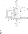
FIG. 1 is a front view of an X-ray inspection apparatus according to an embodiment of the present disclosure; -
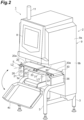
FIG. 2 is a perspective view of the X-ray inspection apparatus inFIG. 1 ; -
FIG. 3 is a plan view of a conveying unit inFIG. 1 ; -
FIG. 4 is a cross-sectional view of the X-ray inspection apparatus taken along a vertical plane passing through a passing region; -
FIG. 5 is a perspective view illustrating a support portion and a swing member attached to first and second conveying units; -
FIG. 6 is a perspective view illustrating the support portion and the swing member as viewed from a back surface side; -
FIG. 7A is a view illustrating a state in which the first and second conveying units are attached and the swing member is placed on the support portion; and -
FIG. 7B is a view illustrating a state in which the first conveying unit is not attached, the second conveying unit is attached, and the swing member hangs down by its own weight. - Hereinafter, an embodiment of the present invention will be described in detail with reference to the drawings. Note that in the description of the drawings, the same elements are denoted by the same reference numerals, and redundant description is omitted.
- As illustrated in
FIG. 1 , anX-ray inspection apparatus 1 includes anapparatus body 2,support legs 3, a shield box (housing) 4, aconveying unit 5, anX-ray irradiation unit 6, anX-ray detection unit 7, a display operation unit (a notification unit) 8, and acontrol unit 10. TheX-ray inspection apparatus 1 generates an X-ray transmission image of an article G while conveying the article G, and inspects the article G based on the X-ray transmission image (for example, storage number inspection, foreign matter mixing inspection, missing inspection, crack and chip inspection, and the like). The article G before the inspection is carried into theX-ray inspection apparatus 1 by a carry-inconveyor 20a. The article G after the inspection is carried out from theX-ray inspection apparatus 1 by a carry-outconveyor 30a. The article G determined as a defective product by theX-ray inspection apparatus 1 is distributed to an outside of a production line by a distribution device (not illustrated) disposed downstream of the carry-outconveyor 30a. The article G determined as a non-defective product by theX-ray inspection apparatus 1 passes through the distribution device as it is. - The
apparatus body 2 houses thecontrol unit 10 and the like. Thesupport legs 3 support theapparatus body 2. Theshield box 4 is provided in theapparatus body 2. Theshield box 4 prevents leakage of X-rays to the outside. An inspection region R in which the article G is inspected by the X-ray is provided inside theshield box 4. A carry-inport 4a and a carry-out port 4b are formed in theshield box 4. The article G before inspection is carried into the inspection region R from the carry-inconveyor 20a through the carry-inport 4a. The article G after inspection is carried out from the inspection region R to the carry-outconveyor 30a via the carry-outport 4b. Each of the carry-inport 4a and the carry-outport 4b is provided with an X-ray shielding curtain (not illustrated) that prevents leakage of X-rays. - The
conveying unit 5 is disposed in theshield box 4. Theconveying unit 5 conveys the article G from the carry-inport 4a to the carry-outport 4b via the inspection region R in a conveying direction A. Theconveying unit 5 is, for example, a belt conveyor stretched between the carry-inport 4a and the carry-outport 4b. - The
apparatus body 2 has, for example, ahousing 9 made of a material capable of shielding electromagnetic waves such as X-rays. As illustrated inFIG. 2 , thehousing 9 includes anupper portion 9a provided with thedisplay operation unit 8 on a front surface thereof, aback portion 9b extending in a vertical direction, and alower portion 9c protruding forward from theback portion 9b. When viewed from the downstream side in the conveying direction A, afirst wall portion 91 of theupper portion 9a, asecond wall portion 92 of theback portion 9b, and athird wall portion 93 of thelower portion 9c form a U-shape opened forward (seeFIG. 4 ), and portions of the carry-inconveyor 20a and the carry-outconveyor 30a near a passing region X (described later) are arranged in a space surrounded by these wall portions. A front surface of theshield box 4 is covered with a shieldingcover 4c that is opened and closed at the time of maintenance or the like. - As illustrated in
FIGS. 1 and4 , theX-ray irradiation unit 6 is disposed, for example, in theupper portion 9a of thehousing 9. TheX-ray irradiation unit 6 irradiates the article G conveyed by the conveyingunit 5 with the X-ray (electromagnetic wave). TheX-ray irradiation unit 6 includes, for example, an X-ray tube that emits the X-ray, and a collimator that spreads the X-ray emitted from the X-ray tube in a fan shape in a plane perpendicular to the conveying direction A. - The
X-ray detection unit 7 is disposed in thelower portion 9c of thehousing 9. TheX-ray detection unit 7 detects the X-ray emitted by theX-ray irradiation unit 6 and transmitted through the article G. TheX-ray detection unit 7 is configured as, for example, a line sensor. Specifically, theX-ray detection unit 7 includes a plurality of photodiodes arranged one-dimensionally in a horizontal direction perpendicular to the conveying direction A, and a scintillator disposed on the X-ray incident side with respect to each photodiode. In this case, in theX-ray detection unit 7, the X-ray incident on the scintillator is converted into light, and the light incident on each photodiode is converted into an electric signal. - As illustrated in
FIGS. 1 and2 , thedisplay operation unit 8 is provided in theupper portion 9a of thehousing 9 and faces forward. Thedisplay operation unit 8 displays various types of information (that is, notifies an operator of an operation state) and receives inputs of various conditions. Thedisplay operation unit 8 is, for example, a liquid crystal display, and displays an operation screen as a touch panel. In this case, the operator can input various conditions via thedisplay operation unit 8. Thedisplay operation unit 8 provides notification of various abnormalities in theX-ray inspection apparatus 1. Anotification lamp 11 also functioning as the notification unit is erected on theupper portion 9a of thehousing 9. - The
control unit 10 is disposed in theapparatus body 2. Thecontrol unit 10 controls an operation of each unit of theX-ray inspection apparatus 1. Thecontrol unit 10 includes a central processing unit (CPU), a read only memory (ROM), a random access memory (RAM), and the like. Thecontrol unit 10 receives an A/D converted signal output from theX-ray detection unit 7. Thecontrol unit 10 functions as an inspection unit that generates the X-ray transmission image of the article G based on the signal output from theX-ray detection unit 7 and inspects the article G based on the X-ray transmission image. - As illustrated in
FIG. 3 , the conveyingunit 5 includes a pair of conveyingunits units FIG. 1 ) from theX-ray irradiation unit 6 to theX-ray detection unit 7 interposed therebetween. Thus, detection sensitivity of the X-ray is improved, and maintainability of the conveyingunit 5 is improved. Note that the passing region X extends in a direction B. The direction B is a third direction intersecting both a first direction (that is, the conveying direction A) in which the conveyingunit 5 conveys the article and a second direction (seeFIG. 1 ) in which theX-ray irradiation unit 6 and theX-ray detection unit 7 face each other. - The conveying
unit 20 disposed upstream in the conveying direction A includes aframe 21, a plurality of conveyingrollers belt 24. Theframe 21 is attached to the apparatus body 2 (shield box 4) via amotor box 26. The conveyingrollers frame 21. As an example, the conveyingroller 23 disposed upstream in the conveying direction A is a driving roller, and the conveyingroller 22 disposed downstream in the conveying direction A is a driven roller. The conveyingbelt 24 is an endless belt, and is stretched between the conveyingrollers unit 20 is attached to theapparatus body 2, a part of theframe 21 is engaged with and fixed to a part of theshield box 4. Theframe 21 and a conveyingsurface 24a of the conveyingbelt 24 extend parallel (horizontally) to the conveying direction A. - The conveying
unit 30 disposed downstream in the conveying direction A includes aframe 31, a plurality of conveyingrollers belt 34. Theframe 31 is attached to the apparatus body 2 (shield box 4) via amotor box 36. The conveyingrollers frame 31. As an example, the conveyingroller 32 disposed downstream in the conveying direction A is a driving roller, and the conveyingroller 33 disposed upstream in the conveying direction A is a driven roller. The conveyingbelt 34 is an endless belt, and is stretched between the conveyingrollers unit 30 is attached to theapparatus body 2, a part of theframe 31 is engaged with and fixed to a part of theshield box 4. Theframe 31 and a conveyingsurface 34a of the conveyingbelt 34 extend parallel (horizontally) to the conveying direction A. - The
X-ray inspection apparatus 1 according to the present embodiment includes adetermination unit 15 that determines attachment of the conveyingunit 20 and the conveyingunit 30. Thedetermination unit 15 determines attachment of both the conveyingunit 20 and the conveyingunit 30 without depending on the X-ray transmission image (without irradiating the X-ray from the X-ray irradiation unit 6). Hereinafter, thedetermination unit 15 will be described with reference toFIGS. 3 to 6 . -
FIG. 5 is a perspective view illustrating a support portion and a swing member attached to the conveyingunit 20 and the conveyingunit 30.FIG. 6 is a perspective view illustrating the support portion and the swing member as viewed from a back surface side. As illustrated inFIGS. 5 and6 , thedetermination unit 15 includes astopper 60 attached to the conveyingunit 20 and anactuator 70 attached to the conveyingunit 30. In thedetermination unit 15, aswing member 74 of theactuator 70 is present at a contact stop position (a predetermined position) P1 in a state where at least a part of theactuator 70 is in contact with thestopper 60. As illustrated inFIGS. 4 and7A , thedetermination unit 15 includes a magnetic proximity switch (a sensor unit) 80 that detects theactuator 70 present at the contact stop position P1. - As illustrated in
FIGS. 4 and7A , thestopper 60 and theactuator 70 are arranged between the conveyingsurface 24a of the conveyingunit 20 and the conveyingsurface 34a of the conveyingunit 30, and asecond wall portion 92 extending in the vertical direction on sides of the conveyingsurfaces stopper 60 and theactuator 70 is set in a region that is not originally used for conveyance by the conveyingunit 5. On the other hand, themagnetic proximity switch 80 is disposed on an inner surface side of thesecond wall portion 92, that is, in theback portion 9b. Themagnetic proximity switch 80 is fixed to thesecond wall portion 92 by aspecial screw 81 so as not to be removed by a general-purpose tool in order to prevent invalidation of an interlock. Thesecond wall portion 92 extends between thestopper 60 and theactuator 70, and themagnetic proximity switch 80. Themagnetic proximity switch 80 detects the presence of theswing member 74 in a non-contact manner. Themagnetic proximity switch 80 can communicate information with thecontrol unit 10, and transmits information indicating the presence or absence of theswing member 74 to thecontrol unit 10. Such communication means may be provided separately from themagnetic proximity switch 80. - As illustrated in
FIG. 3 , thestopper 60 is fixed to theframe 21 of the conveyingunit 20 and extends downstream in the conveying direction A (toward the conveying unit 30). Theactuator 70 is fixed to theframe 31 of the conveyingunit 30 and extends upstream in the conveying direction A (toward the conveying unit 20). Each of the conveyingunit 20 and the conveyingunit 30 is detachable from theapparatus body 2 when the operation of theX-ray inspection apparatus 1 is stopped. As illustrated inFIG. 2 , the conveyingunit 20 is rotated as a whole about apin 27 attached to theframe 21, as the operator lifts a portion near the conveyingroller 22 by hand. The conveyingunit 30 is rotated as a whole about apin 37 attached to theframe 31, as the operator lifts a portion near the conveyingroller 33 by hand. Both a rotation axis L2 passing through thepin 27 and a rotation axis L3 passing through thepin 37 extend parallel to the direction B. The conveyingunit 20 and the conveyingunit 30 are separated from the apparatus body 2 (shield box 4) by being respectively detached from themotor box 26 and themotor box 36 after rotation. At this time, since thestopper 60 is integrated with theframe 21, it is removed together with the conveyingunit 20. Since theactuator 70 is integrated with theframe 31, it is removed together with the conveyingunit 30. - Configurations of the
stopper 60 and theactuator 70 will be described in detail. As illustrated inFIGS. 5 and6 , thestopper 60 includes abase plate 61 fixed to theframe 21 and a support base (support portion) 62 provided at a tip of thebase plate 61 and extending, for example, flatly. An upper surface of thesupport base 62 is, for example, parallel to the conveyingsurface 24a of the conveyingbelt 24. Theactuator 70 includes abase portion 71 fixed to theframe 31, asupport shaft 72 supported by a pair ofsupport plate portions 71a of thebase portion 71, and anarm member 73 and aswing member 74 swingably supported by thesupport shaft 72. Thesupport shaft 72 is, for example, parallel to the conveyingsurface 34a of the conveyingbelt 34. - As illustrated in
FIGS. 5 and6 , thesupport shaft 72 includes a smalldiameter shaft portion 72a provided at an upstream portion thereof in the conveying direction A. Thearm member 73 includes a pair oftriangular arm portions 73a swingably supported by the smalldiameter shaft portion 72a and abottom plate portion 73c provided at a tip of thearm portion 73a. Theswing member 74 includes a holdingportion 76 to which thebottom plate portion 73c is fixed and amagnet 77 held by the holdingportion 76. Thestopper 60 is manufactured by, for example, bending a plate material made of metal. Theactuator 70, except for themagnet 77, is manufactured by, for example, bending a plate material made of metal. An outer surface of themagnet 77 located farther from thesupport shaft 72 is not covered by the holdingportion 76 and is exposed to the outside. - The
magnet 77 is, for example, a block-shaped permanent magnet. Theswing member 74 including the holdingportion 76 and themagnet 77 integrated together swings in a predetermined range around thesupport shaft 72. As illustrated inFIGS. 5 and7A , thearm portion 73a includes abase end portion 73b having an acute angle shape on the opposite side of theswing member 74 with respect to thesupport shaft 72. When thearm member 73 swings counterclockwise as illustrated inFIG. 7A , since thebase end portion 73b of thearm portion 73a comes into contact with a part of thebase portion 71, further swinging (rotation) of thearm member 73 is stopped. Further, when thearm member 73 swings clockwise illustrated inFIG. 7A , since the holdingportion 76 of thearm portion 73a comes into contact with a part of the conveyingunit 20 and the conveying unit 30 (for example, a part of theframe 31 or the frame 21), further swinging (rotation) of thearm member 73 is stopped. As described above, the conveyingunit 30 is provided with arestriction mechanism 70X that restricts a swing range of theswing member 74. - In a state where the conveying
unit 20 and the conveyingunit 30 are attached to theapparatus body 2, as illustrated inFIGS. 3 and6 , thesupport base 62 of thestopper 60 and theswing member 74 of theactuator 70 are located between the conveyingunit 20 and the conveyingunit 30 in the conveying direction A. In other words, thesupport base 62 and theswing member 74 are located at positions where at least a part thereof overlaps with each other in plan view. A position where thesupport base 62 and theswing member 74 overlap is a contact position in thedetermination unit 15. If the conveyingunit 20 is not attached but the conveyingunit 30 is attached, thesupport base 62 is not present at the contact position. When the conveyingunit 30 is attached to theapparatus body 2 and located at an operable position, thearm member 73 and theswing member 74 hang down by their own weight and are located at a natural hanging position P2 (seeFIG. 7B ). The natural hanging position P2 is within a swing range of thearm member 73 described above. - As illustrated in
FIG. 7A , themagnetic proximity switch 80 detects that theswing member 74 is present at the contact stop position P1 in a state where theswing member 74 is in contact with the support base 62 (in the present embodiment, the holdingportion 76 is placed on the support base 62). When theswing member 74 is at the contact stop position P1, a sensor surface of themagnetic proximity switch 80 is parallel to the outer surface of themagnet 77. Themagnetic proximity switch 80 approaches the contact stop position P1. The contact stop position P1 is equal to the contact position described above. The contact position, that is, a position of a top surface ofsupport base 62 is located closer to themagnetic proximity switch 80 than immediately below the support shaft 72 (or thesupport plate portion 71a). As illustrated inFIG. 7B , when theswing member 74 is lowered to the natural hanging position P2 due to the absence of thesupport base 62, themagnetic proximity switch 80 detects that theswing member 74 is not present at the contact stop position P1. That is, themagnet 77 present at the contact stop position P1 turns on themagnetic proximity switch 80, and themagnet 77 present at the natural hanging position P2 turns off themagnetic proximity switch 80. The natural hanging position P2 is located immediately below the support shaft 72 (or thesupport plate portion 71 a), and thus is farther from themagnetic proximity switch 80 than the contact stop position P1. - As described above, the
determination unit 15 is an interlock switch mechanism that detects that two conveyors are appropriately installed. Thecontrol unit 10 determines whether both of the conveyingunits magnetic proximity switch 80. - For example, in a case where the conveying
unit 20 is attached and the conveyingunit 30 is not attached, since the swing member 74 (magnet 77) is not present near themagnetic proximity switch 80, thecontrol unit 10 can determine that both of the conveyingunits unit 30 is attached and the conveyingunit 20 is not attached, since theswing member 74 is located at the natural hanging position P2, thecontrol unit 10 can determine that both of the conveyingunits - According to an appropriate conveyor attachment procedure, the operator first attaches the conveying
unit 20 and subsequently attaches the conveyingunit 30. Thus, the actuator 70 approaches thestopper 60 from above, and the holdingportion 76 is placed on thesupport base 62. In a case where both of the pair of conveyingunits swing member 74 is located at the contact stop position P1, thecontrol unit 10 can determine that both of the conveyingunits unit 30 is attached first, since the presence of theactuator 70 prevents thestopper 60 from descending, it is physically impossible to attach the conveyingunit 20. Therefore, also in this case, theswing member 74 is located at the natural hanging position P2, and thecontrol unit 10 can determine that both of the conveyingunits - When determining that both of the pair of conveying
units control unit 10 stops X-ray irradiation by theX-ray irradiation unit 6. Further, thecontrol unit 10 controls thedisplay operation unit 8 to display a result of determination described above. Thecontrol unit 10 controls thenotification lamp 11 to provide notification of the result of the determination described above. - According to the
X-ray inspection apparatus 1 of the present embodiment, when the conveyingunit 20 is attached and the conveyingunit 30 is further attached, at least a part of theswing member 74 is in contact with thesupport base 62 and located at the contact stop position P1. Then, only when this state (condition) is established, themagnetic proximity switch 80 detects that theswing member 74 is present at the predetermined position. Therefore, attachment of the pair of conveyingunits magnetic proximity switch 80. - A position of the
swing member 74 can be detected in a non-contact manner by detection of themagnet 77 by themagnetic proximity switch 80. Thus, configuration of themagnetic proximity switch 80 is simplified, and the degree of freedom in layout is also high. - Since the
magnetic proximity switch 80 is disposed inside thehousing 9, a wide area of the conveyingsurfaces - Since the
restriction mechanism 70X restricts the swing range of theswing member 74, when the conveyingunit 30 is attached, theswing member 74 can be appropriately and reliably brought into contact with thesupport base 62. - In the
X-ray inspection apparatus 1, thecontrol unit 10 stops the X-ray irradiation when thedetermination unit 15 does not determine attachment of the conveyingunits X-ray inspection apparatus 1 from being erroneously operated. - Further, in the
X-ray inspection apparatus 1, when thedetermination unit 15 does not determine attachment of the conveyingunits control unit 10 provides notification that there is an abnormality. Thus, theX-ray inspection apparatus 1 is prevented from being erroneously operated, and theX-ray inspection apparatus 1 can be stopped even when any of the conveying units is detached during operation. - Although the embodiment of the present disclosure has been described above, the present invention is not limited to the above embodiment. For example, the
actuator 70 may be attached to the conveyingunit 20, and thestopper 60 may be attached to the conveyingunit 30. In this case, the conveyingunit 20 corresponds to the second conveying unit, and the conveyingunit 30 corresponds to the first conveying unit. The sensor unit may be a contact type switch instead of themagnetic proximity switch 80. - The electromagnetic wave irradiated by the irradiation unit and detected by the detection unit is not limited to the X-ray.
- At least a part of the embodiment described above may be arbitrarily combined.
Claims (6)
- An X-ray inspection apparatus comprising:a conveying unit configured to convey an article;an irradiation unit configured to irradiate the article conveyed by the conveying unit with an electromagnetic wave;a detection unit configured to detect the electromagnetic wave emitted from the irradiation unit and transmitted through the article;an inspection unit configured to inspect the article based on a detection result of the detection unit; anda determination unit configured to determine attachment of the conveying unit, whereinthe conveying unit includes first and second conveying units arranged side by side with a passing region through which the electromagnetic wave from the irradiation unit to the detection unit passes therebetween, andthe determination unit includes:a support portion attached to the first conveying unit;a swing member swingably attached to the second conveying unit and at least partially in contact with the support portion when the first and second conveying units are attached; anda sensor unit configured to detect whether the swing member is present at a predetermined position in a state where the swing member is in contact with the support portion.
- The X-ray inspection apparatus according to claim 1, whereinthe swing member includes a magnet, andthe sensor unit is a magnetic proximity switch for detecting whether the magnet is present at a predetermined position.
- The X-ray inspection apparatus according to claim 1 or 2, whereinthe support portion and the swing member are arranged between a conveying surface of the first and second conveying units and a side wall of a housing extending in a vertical direction on a side of the conveying surface, andthe sensor unit is disposed on an inner surface side of the side wall.
- The X-ray inspection apparatus according to any one of claims 1 to 3, wherein the second conveying unit is provided with a restriction mechanism for restricting a swing range of the swing member.
- The X-ray inspection apparatus according to any one of claims 1 to 4, wherein the inspection unit stops irradiation with the electromagnetic wave when the determination unit does not determine attachment of the first and second conveying units.
- The X-ray inspection apparatus according to any one of claims 1 to 5, wherein the inspection unit provides notification that there is an abnormality when the determination unit does not determine attachment of the first and second conveying units.
Applications Claiming Priority (1)
| Application Number | Priority Date | Filing Date | Title |
|---|---|---|---|
| JP2023043847A JP2024133852A (en) | 2023-03-20 | 2023-03-20 | X-ray inspection equipment |
Publications (1)
| Publication Number | Publication Date |
|---|---|
| EP4434919A1 true EP4434919A1 (en) | 2024-09-25 |
Family
ID=90366539
Family Applications (1)
| Application Number | Title | Priority Date | Filing Date |
|---|---|---|---|
| EP24163950.9A Pending EP4434919A1 (en) | 2023-03-20 | 2024-03-15 | X-ray inspection apparatus |
Country Status (4)
| Country | Link |
|---|---|
| US (1) | US20240319117A1 (en) |
| EP (1) | EP4434919A1 (en) |
| JP (1) | JP2024133852A (en) |
| CN (1) | CN118671105A (en) |
Citations (3)
| Publication number | Priority date | Publication date | Assignee | Title |
|---|---|---|---|---|
| US5749452A (en) * | 1995-07-27 | 1998-05-12 | R.A. Hanson Company, Inc. | Mobile conveyor including alignment system |
| JP2018155561A (en) | 2017-03-16 | 2018-10-04 | 株式会社イシダ | X-ray inspection device |
| EP4130725A1 (en) * | 2020-08-26 | 2023-02-08 | Hamamatsu Photonics K.K. | Foreign matter inspection device |
-
2023
- 2023-03-20 JP JP2023043847A patent/JP2024133852A/en active Pending
-
2024
- 2024-03-14 US US18/605,787 patent/US20240319117A1/en active Pending
- 2024-03-15 EP EP24163950.9A patent/EP4434919A1/en active Pending
- 2024-03-15 CN CN202410299946.6A patent/CN118671105A/en active Pending
Patent Citations (3)
| Publication number | Priority date | Publication date | Assignee | Title |
|---|---|---|---|---|
| US5749452A (en) * | 1995-07-27 | 1998-05-12 | R.A. Hanson Company, Inc. | Mobile conveyor including alignment system |
| JP2018155561A (en) | 2017-03-16 | 2018-10-04 | 株式会社イシダ | X-ray inspection device |
| EP4130725A1 (en) * | 2020-08-26 | 2023-02-08 | Hamamatsu Photonics K.K. | Foreign matter inspection device |
Also Published As
| Publication number | Publication date |
|---|---|
| US20240319117A1 (en) | 2024-09-26 |
| CN118671105A (en) | 2024-09-20 |
| JP2024133852A (en) | 2024-10-03 |
Similar Documents
| Publication | Publication Date | Title |
|---|---|---|
| KR101278920B1 (en) | X-ray inspection apparatus and x-ray inspection method | |
| CN115104025B (en) | Hand baggage inspection device | |
| WO2009157121A1 (en) | X-ray inspection apparatus | |
| JPH08178872A (en) | X-ray nondestructive inspection device | |
| CN116511084A (en) | Inspection device, X-ray device and weighing device integrated therein | |
| JP2002148214A (en) | X-ray inspection equipment | |
| JP3828733B2 (en) | X-ray foreign object detection device | |
| US20240319117A1 (en) | X-ray inspection apparatus | |
| JP6830243B2 (en) | X-ray inspection equipment | |
| EP4671748A2 (en) | INSPECTION DEVICE | |
| CN1898556B (en) | X-ray inspection device | |
| US11940393B2 (en) | X-ray inspection apparatus | |
| JP2006071514A (en) | X-ray inspection equipment | |
| JP2018048863A (en) | X-ray inspection equipment | |
| JP3946609B2 (en) | X-ray inspection equipment | |
| EP4435417A1 (en) | X-ray inspection apparatus | |
| EP4603828A1 (en) | X-ray inspection apparatus | |
| CN217931459U (en) | Conveying type article security inspection machine | |
| JP2022137256A (en) | X-ray inspection device | |
| EP4700377A1 (en) | X-ray inspection apparatus | |
| CN120404799A (en) | Shielding unit and X-ray inspection device | |
| JP7328802B2 (en) | inspection equipment | |
| JP7764187B2 (en) | Inspection Equipment | |
| JP2006058134A (en) | X-ray inspection equipment | |
| JP2023086228A (en) | X-ray inspection device |
Legal Events
| Date | Code | Title | Description |
|---|---|---|---|
| PUAI | Public reference made under article 153(3) epc to a published international application that has entered the european phase |
Free format text: ORIGINAL CODE: 0009012 |
|
| STAA | Information on the status of an ep patent application or granted ep patent |
Free format text: STATUS: REQUEST FOR EXAMINATION WAS MADE |
|
| 17P | Request for examination filed |
Effective date: 20240315 |
|
| AK | Designated contracting states |
Kind code of ref document: A1 Designated state(s): AL AT BE BG CH CY CZ DE DK EE ES FI FR GB GR HR HU IE IS IT LI LT LU LV MC ME MK MT NL NO PL PT RO RS SE SI SK SM TR |
|
| GRAP | Despatch of communication of intention to grant a patent |
Free format text: ORIGINAL CODE: EPIDOSNIGR1 |
|
| STAA | Information on the status of an ep patent application or granted ep patent |
Free format text: STATUS: GRANT OF PATENT IS INTENDED |
|
| RIC1 | Information provided on ipc code assigned before grant |
Ipc: B65G 21/10 20060101AFI20260127BHEP Ipc: B65G 43/10 20060101ALI20260127BHEP Ipc: G01N 23/04 20180101ALI20260127BHEP |
|
| INTG | Intention to grant announced |
Effective date: 20260211 |