EP4434909A1 - Auxiliary unit for stacking packaging material - Google Patents
Auxiliary unit for stacking packaging material Download PDFInfo
- Publication number
- EP4434909A1 EP4434909A1 EP23186045.3A EP23186045A EP4434909A1 EP 4434909 A1 EP4434909 A1 EP 4434909A1 EP 23186045 A EP23186045 A EP 23186045A EP 4434909 A1 EP4434909 A1 EP 4434909A1
- Authority
- EP
- European Patent Office
- Prior art keywords
- packing material
- load
- auxiliary unit
- load receiving
- side surfaces
- Prior art date
- Legal status (The legal status is an assumption and is not a legal conclusion. Google has not performed a legal analysis and makes no representation as to the accuracy of the status listed.)
- Pending
Links
Images



Classifications
-
- B—PERFORMING OPERATIONS; TRANSPORTING
- B65—CONVEYING; PACKING; STORING; HANDLING THIN OR FILAMENTARY MATERIAL
- B65D—CONTAINERS FOR STORAGE OR TRANSPORT OF ARTICLES OR MATERIALS, e.g. BAGS, BARRELS, BOTTLES, BOXES, CANS, CARTONS, CRATES, DRUMS, JARS, TANKS, HOPPERS, FORWARDING CONTAINERS; ACCESSORIES, CLOSURES, OR FITTINGS THEREFOR; PACKAGING ELEMENTS; PACKAGES
- B65D21/00—Nestable, stackable or joinable containers; Containers of variable capacity
- B65D21/02—Containers specially shaped, or provided with fittings or attachments, to facilitate nesting, stacking, or joining together
- B65D21/0209—Containers specially shaped, or provided with fittings or attachments, to facilitate nesting, stacking, or joining together stackable or joined together one-upon-the-other in the upright or upside-down position
- B65D21/0224—Auxiliary removable stacking elements other than covers
-
- B—PERFORMING OPERATIONS; TRANSPORTING
- B65—CONVEYING; PACKING; STORING; HANDLING THIN OR FILAMENTARY MATERIAL
- B65D—CONTAINERS FOR STORAGE OR TRANSPORT OF ARTICLES OR MATERIALS, e.g. BAGS, BARRELS, BOTTLES, BOXES, CANS, CARTONS, CRATES, DRUMS, JARS, TANKS, HOPPERS, FORWARDING CONTAINERS; ACCESSORIES, CLOSURES, OR FITTINGS THEREFOR; PACKAGING ELEMENTS; PACKAGES
- B65D81/00—Containers, packaging elements, or packages, for contents presenting particular transport or storage problems, or adapted to be used for non-packaging purposes after removal of contents
- B65D81/02—Containers, packaging elements, or packages, for contents presenting particular transport or storage problems, or adapted to be used for non-packaging purposes after removal of contents specially adapted to protect contents from mechanical damage
- B65D81/05—Containers, packaging elements, or packages, for contents presenting particular transport or storage problems, or adapted to be used for non-packaging purposes after removal of contents specially adapted to protect contents from mechanical damage maintaining contents at spaced relation from package walls, or from other contents
- B65D81/053—Corner, edge or end protectors
- B65D81/055—Protectors contacting three surfaces of the packaged article, e.g. three-sided edge protectors
- B65D81/056—Protectors contacting three surfaces of the packaged article, e.g. three-sided edge protectors the surfaces being generally perpendicular to each other, e.g. three-sided corner protectors
-
- B—PERFORMING OPERATIONS; TRANSPORTING
- B65—CONVEYING; PACKING; STORING; HANDLING THIN OR FILAMENTARY MATERIAL
- B65D—CONTAINERS FOR STORAGE OR TRANSPORT OF ARTICLES OR MATERIALS, e.g. BAGS, BARRELS, BOTTLES, BOXES, CANS, CARTONS, CRATES, DRUMS, JARS, TANKS, HOPPERS, FORWARDING CONTAINERS; ACCESSORIES, CLOSURES, OR FITTINGS THEREFOR; PACKAGING ELEMENTS; PACKAGES
- B65D19/00—Pallets or like platforms, with or without side walls, for supporting loads to be lifted or lowered
- B65D19/02—Rigid pallets with side walls, e.g. box pallets
- B65D19/06—Rigid pallets with side walls, e.g. box pallets with bodies formed by uniting or interconnecting two or more components
-
- B—PERFORMING OPERATIONS; TRANSPORTING
- B65—CONVEYING; PACKING; STORING; HANDLING THIN OR FILAMENTARY MATERIAL
- B65D—CONTAINERS FOR STORAGE OR TRANSPORT OF ARTICLES OR MATERIALS, e.g. BAGS, BARRELS, BOTTLES, BOXES, CANS, CARTONS, CRATES, DRUMS, JARS, TANKS, HOPPERS, FORWARDING CONTAINERS; ACCESSORIES, CLOSURES, OR FITTINGS THEREFOR; PACKAGING ELEMENTS; PACKAGES
- B65D2519/00—Pallets or like platforms, with or without side walls, for supporting loads to be lifted or lowered
- B65D2519/00004—Details relating to pallets
- B65D2519/00009—Materials
- B65D2519/00014—Materials for the load supporting surface
- B65D2519/00024—Metal
-
- B—PERFORMING OPERATIONS; TRANSPORTING
- B65—CONVEYING; PACKING; STORING; HANDLING THIN OR FILAMENTARY MATERIAL
- B65D—CONTAINERS FOR STORAGE OR TRANSPORT OF ARTICLES OR MATERIALS, e.g. BAGS, BARRELS, BOTTLES, BOXES, CANS, CARTONS, CRATES, DRUMS, JARS, TANKS, HOPPERS, FORWARDING CONTAINERS; ACCESSORIES, CLOSURES, OR FITTINGS THEREFOR; PACKAGING ELEMENTS; PACKAGES
- B65D2519/00—Pallets or like platforms, with or without side walls, for supporting loads to be lifted or lowered
- B65D2519/00004—Details relating to pallets
- B65D2519/00009—Materials
- B65D2519/00014—Materials for the load supporting surface
- B65D2519/00029—Wood
-
- B—PERFORMING OPERATIONS; TRANSPORTING
- B65—CONVEYING; PACKING; STORING; HANDLING THIN OR FILAMENTARY MATERIAL
- B65D—CONTAINERS FOR STORAGE OR TRANSPORT OF ARTICLES OR MATERIALS, e.g. BAGS, BARRELS, BOTTLES, BOXES, CANS, CARTONS, CRATES, DRUMS, JARS, TANKS, HOPPERS, FORWARDING CONTAINERS; ACCESSORIES, CLOSURES, OR FITTINGS THEREFOR; PACKAGING ELEMENTS; PACKAGES
- B65D2519/00—Pallets or like platforms, with or without side walls, for supporting loads to be lifted or lowered
- B65D2519/00004—Details relating to pallets
- B65D2519/00009—Materials
- B65D2519/00014—Materials for the load supporting surface
- B65D2519/00034—Plastic
-
- B—PERFORMING OPERATIONS; TRANSPORTING
- B65—CONVEYING; PACKING; STORING; HANDLING THIN OR FILAMENTARY MATERIAL
- B65D—CONTAINERS FOR STORAGE OR TRANSPORT OF ARTICLES OR MATERIALS, e.g. BAGS, BARRELS, BOTTLES, BOXES, CANS, CARTONS, CRATES, DRUMS, JARS, TANKS, HOPPERS, FORWARDING CONTAINERS; ACCESSORIES, CLOSURES, OR FITTINGS THEREFOR; PACKAGING ELEMENTS; PACKAGES
- B65D2519/00—Pallets or like platforms, with or without side walls, for supporting loads to be lifted or lowered
- B65D2519/00004—Details relating to pallets
- B65D2519/00009—Materials
- B65D2519/00049—Materials for the base surface
- B65D2519/00059—Metal
-
- B—PERFORMING OPERATIONS; TRANSPORTING
- B65—CONVEYING; PACKING; STORING; HANDLING THIN OR FILAMENTARY MATERIAL
- B65D—CONTAINERS FOR STORAGE OR TRANSPORT OF ARTICLES OR MATERIALS, e.g. BAGS, BARRELS, BOTTLES, BOXES, CANS, CARTONS, CRATES, DRUMS, JARS, TANKS, HOPPERS, FORWARDING CONTAINERS; ACCESSORIES, CLOSURES, OR FITTINGS THEREFOR; PACKAGING ELEMENTS; PACKAGES
- B65D2519/00—Pallets or like platforms, with or without side walls, for supporting loads to be lifted or lowered
- B65D2519/00004—Details relating to pallets
- B65D2519/00009—Materials
- B65D2519/00049—Materials for the base surface
- B65D2519/00064—Wood
-
- B—PERFORMING OPERATIONS; TRANSPORTING
- B65—CONVEYING; PACKING; STORING; HANDLING THIN OR FILAMENTARY MATERIAL
- B65D—CONTAINERS FOR STORAGE OR TRANSPORT OF ARTICLES OR MATERIALS, e.g. BAGS, BARRELS, BOTTLES, BOXES, CANS, CARTONS, CRATES, DRUMS, JARS, TANKS, HOPPERS, FORWARDING CONTAINERS; ACCESSORIES, CLOSURES, OR FITTINGS THEREFOR; PACKAGING ELEMENTS; PACKAGES
- B65D2519/00—Pallets or like platforms, with or without side walls, for supporting loads to be lifted or lowered
- B65D2519/00004—Details relating to pallets
- B65D2519/00009—Materials
- B65D2519/00049—Materials for the base surface
- B65D2519/00069—Plastic
-
- B—PERFORMING OPERATIONS; TRANSPORTING
- B65—CONVEYING; PACKING; STORING; HANDLING THIN OR FILAMENTARY MATERIAL
- B65D—CONTAINERS FOR STORAGE OR TRANSPORT OF ARTICLES OR MATERIALS, e.g. BAGS, BARRELS, BOTTLES, BOXES, CANS, CARTONS, CRATES, DRUMS, JARS, TANKS, HOPPERS, FORWARDING CONTAINERS; ACCESSORIES, CLOSURES, OR FITTINGS THEREFOR; PACKAGING ELEMENTS; PACKAGES
- B65D2519/00—Pallets or like platforms, with or without side walls, for supporting loads to be lifted or lowered
- B65D2519/00004—Details relating to pallets
- B65D2519/00009—Materials
- B65D2519/00119—Materials for the construction of the reinforcements
- B65D2519/00139—Plastic
-
- B—PERFORMING OPERATIONS; TRANSPORTING
- B65—CONVEYING; PACKING; STORING; HANDLING THIN OR FILAMENTARY MATERIAL
- B65D—CONTAINERS FOR STORAGE OR TRANSPORT OF ARTICLES OR MATERIALS, e.g. BAGS, BARRELS, BOTTLES, BOXES, CANS, CARTONS, CRATES, DRUMS, JARS, TANKS, HOPPERS, FORWARDING CONTAINERS; ACCESSORIES, CLOSURES, OR FITTINGS THEREFOR; PACKAGING ELEMENTS; PACKAGES
- B65D2519/00—Pallets or like platforms, with or without side walls, for supporting loads to be lifted or lowered
- B65D2519/00004—Details relating to pallets
- B65D2519/00009—Materials
- B65D2519/00154—Materials for the side walls
- B65D2519/00159—Paper
-
- B—PERFORMING OPERATIONS; TRANSPORTING
- B65—CONVEYING; PACKING; STORING; HANDLING THIN OR FILAMENTARY MATERIAL
- B65D—CONTAINERS FOR STORAGE OR TRANSPORT OF ARTICLES OR MATERIALS, e.g. BAGS, BARRELS, BOTTLES, BOXES, CANS, CARTONS, CRATES, DRUMS, JARS, TANKS, HOPPERS, FORWARDING CONTAINERS; ACCESSORIES, CLOSURES, OR FITTINGS THEREFOR; PACKAGING ELEMENTS; PACKAGES
- B65D2519/00—Pallets or like platforms, with or without side walls, for supporting loads to be lifted or lowered
- B65D2519/00004—Details relating to pallets
- B65D2519/00009—Materials
- B65D2519/00154—Materials for the side walls
- B65D2519/00164—Metal
-
- B—PERFORMING OPERATIONS; TRANSPORTING
- B65—CONVEYING; PACKING; STORING; HANDLING THIN OR FILAMENTARY MATERIAL
- B65D—CONTAINERS FOR STORAGE OR TRANSPORT OF ARTICLES OR MATERIALS, e.g. BAGS, BARRELS, BOTTLES, BOXES, CANS, CARTONS, CRATES, DRUMS, JARS, TANKS, HOPPERS, FORWARDING CONTAINERS; ACCESSORIES, CLOSURES, OR FITTINGS THEREFOR; PACKAGING ELEMENTS; PACKAGES
- B65D2519/00—Pallets or like platforms, with or without side walls, for supporting loads to be lifted or lowered
- B65D2519/00004—Details relating to pallets
- B65D2519/00009—Materials
- B65D2519/00154—Materials for the side walls
- B65D2519/00169—Wood
-
- B—PERFORMING OPERATIONS; TRANSPORTING
- B65—CONVEYING; PACKING; STORING; HANDLING THIN OR FILAMENTARY MATERIAL
- B65D—CONTAINERS FOR STORAGE OR TRANSPORT OF ARTICLES OR MATERIALS, e.g. BAGS, BARRELS, BOTTLES, BOXES, CANS, CARTONS, CRATES, DRUMS, JARS, TANKS, HOPPERS, FORWARDING CONTAINERS; ACCESSORIES, CLOSURES, OR FITTINGS THEREFOR; PACKAGING ELEMENTS; PACKAGES
- B65D2519/00—Pallets or like platforms, with or without side walls, for supporting loads to be lifted or lowered
- B65D2519/00004—Details relating to pallets
- B65D2519/00009—Materials
- B65D2519/00154—Materials for the side walls
- B65D2519/00174—Plastic
-
- B—PERFORMING OPERATIONS; TRANSPORTING
- B65—CONVEYING; PACKING; STORING; HANDLING THIN OR FILAMENTARY MATERIAL
- B65D—CONTAINERS FOR STORAGE OR TRANSPORT OF ARTICLES OR MATERIALS, e.g. BAGS, BARRELS, BOTTLES, BOXES, CANS, CARTONS, CRATES, DRUMS, JARS, TANKS, HOPPERS, FORWARDING CONTAINERS; ACCESSORIES, CLOSURES, OR FITTINGS THEREFOR; PACKAGING ELEMENTS; PACKAGES
- B65D2519/00—Pallets or like platforms, with or without side walls, for supporting loads to be lifted or lowered
- B65D2519/00004—Details relating to pallets
- B65D2519/00258—Overall construction
- B65D2519/00263—Overall construction of the pallet
- B65D2519/00268—Overall construction of the pallet made of one piece
-
- B—PERFORMING OPERATIONS; TRANSPORTING
- B65—CONVEYING; PACKING; STORING; HANDLING THIN OR FILAMENTARY MATERIAL
- B65D—CONTAINERS FOR STORAGE OR TRANSPORT OF ARTICLES OR MATERIALS, e.g. BAGS, BARRELS, BOTTLES, BOXES, CANS, CARTONS, CRATES, DRUMS, JARS, TANKS, HOPPERS, FORWARDING CONTAINERS; ACCESSORIES, CLOSURES, OR FITTINGS THEREFOR; PACKAGING ELEMENTS; PACKAGES
- B65D2519/00—Pallets or like platforms, with or without side walls, for supporting loads to be lifted or lowered
- B65D2519/00004—Details relating to pallets
- B65D2519/00258—Overall construction
- B65D2519/00263—Overall construction of the pallet
- B65D2519/00273—Overall construction of the pallet made of more than one piece
-
- B—PERFORMING OPERATIONS; TRANSPORTING
- B65—CONVEYING; PACKING; STORING; HANDLING THIN OR FILAMENTARY MATERIAL
- B65D—CONTAINERS FOR STORAGE OR TRANSPORT OF ARTICLES OR MATERIALS, e.g. BAGS, BARRELS, BOTTLES, BOXES, CANS, CARTONS, CRATES, DRUMS, JARS, TANKS, HOPPERS, FORWARDING CONTAINERS; ACCESSORIES, CLOSURES, OR FITTINGS THEREFOR; PACKAGING ELEMENTS; PACKAGES
- B65D2519/00—Pallets or like platforms, with or without side walls, for supporting loads to be lifted or lowered
- B65D2519/00004—Details relating to pallets
- B65D2519/00258—Overall construction
- B65D2519/00283—Overall construction of the load supporting surface
- B65D2519/00288—Overall construction of the load supporting surface made of one piece
-
- B—PERFORMING OPERATIONS; TRANSPORTING
- B65—CONVEYING; PACKING; STORING; HANDLING THIN OR FILAMENTARY MATERIAL
- B65D—CONTAINERS FOR STORAGE OR TRANSPORT OF ARTICLES OR MATERIALS, e.g. BAGS, BARRELS, BOTTLES, BOXES, CANS, CARTONS, CRATES, DRUMS, JARS, TANKS, HOPPERS, FORWARDING CONTAINERS; ACCESSORIES, CLOSURES, OR FITTINGS THEREFOR; PACKAGING ELEMENTS; PACKAGES
- B65D2519/00—Pallets or like platforms, with or without side walls, for supporting loads to be lifted or lowered
- B65D2519/00004—Details relating to pallets
- B65D2519/00258—Overall construction
- B65D2519/00313—Overall construction of the base surface
- B65D2519/00318—Overall construction of the base surface made of one piece
-
- B—PERFORMING OPERATIONS; TRANSPORTING
- B65—CONVEYING; PACKING; STORING; HANDLING THIN OR FILAMENTARY MATERIAL
- B65D—CONTAINERS FOR STORAGE OR TRANSPORT OF ARTICLES OR MATERIALS, e.g. BAGS, BARRELS, BOTTLES, BOXES, CANS, CARTONS, CRATES, DRUMS, JARS, TANKS, HOPPERS, FORWARDING CONTAINERS; ACCESSORIES, CLOSURES, OR FITTINGS THEREFOR; PACKAGING ELEMENTS; PACKAGES
- B65D2519/00—Pallets or like platforms, with or without side walls, for supporting loads to be lifted or lowered
- B65D2519/00004—Details relating to pallets
- B65D2519/00258—Overall construction
- B65D2519/00313—Overall construction of the base surface
- B65D2519/00323—Overall construction of the base surface made of more than one piece
-
- B—PERFORMING OPERATIONS; TRANSPORTING
- B65—CONVEYING; PACKING; STORING; HANDLING THIN OR FILAMENTARY MATERIAL
- B65D—CONTAINERS FOR STORAGE OR TRANSPORT OF ARTICLES OR MATERIALS, e.g. BAGS, BARRELS, BOTTLES, BOXES, CANS, CARTONS, CRATES, DRUMS, JARS, TANKS, HOPPERS, FORWARDING CONTAINERS; ACCESSORIES, CLOSURES, OR FITTINGS THEREFOR; PACKAGING ELEMENTS; PACKAGES
- B65D2519/00—Pallets or like platforms, with or without side walls, for supporting loads to be lifted or lowered
- B65D2519/00004—Details relating to pallets
- B65D2519/00258—Overall construction
- B65D2519/00313—Overall construction of the base surface
- B65D2519/00328—Overall construction of the base surface shape of the contact surface of the base
- B65D2519/00338—Overall construction of the base surface shape of the contact surface of the base contact surface having a discrete foot-like shape
-
- B—PERFORMING OPERATIONS; TRANSPORTING
- B65—CONVEYING; PACKING; STORING; HANDLING THIN OR FILAMENTARY MATERIAL
- B65D—CONTAINERS FOR STORAGE OR TRANSPORT OF ARTICLES OR MATERIALS, e.g. BAGS, BARRELS, BOTTLES, BOXES, CANS, CARTONS, CRATES, DRUMS, JARS, TANKS, HOPPERS, FORWARDING CONTAINERS; ACCESSORIES, CLOSURES, OR FITTINGS THEREFOR; PACKAGING ELEMENTS; PACKAGES
- B65D2519/00—Pallets or like platforms, with or without side walls, for supporting loads to be lifted or lowered
- B65D2519/00004—Details relating to pallets
- B65D2519/00258—Overall construction
- B65D2519/00398—Overall construction reinforcements
- B65D2519/00432—Non-integral, e.g. inserts
- B65D2519/00452—Non-integral, e.g. inserts on the walls
-
- B—PERFORMING OPERATIONS; TRANSPORTING
- B65—CONVEYING; PACKING; STORING; HANDLING THIN OR FILAMENTARY MATERIAL
- B65D—CONTAINERS FOR STORAGE OR TRANSPORT OF ARTICLES OR MATERIALS, e.g. BAGS, BARRELS, BOTTLES, BOXES, CANS, CARTONS, CRATES, DRUMS, JARS, TANKS, HOPPERS, FORWARDING CONTAINERS; ACCESSORIES, CLOSURES, OR FITTINGS THEREFOR; PACKAGING ELEMENTS; PACKAGES
- B65D2519/00—Pallets or like platforms, with or without side walls, for supporting loads to be lifted or lowered
- B65D2519/00004—Details relating to pallets
- B65D2519/00258—Overall construction
- B65D2519/00492—Overall construction of the side walls
- B65D2519/00497—Overall construction of the side walls whereby at least one side wall is made of one piece
-
- B—PERFORMING OPERATIONS; TRANSPORTING
- B65—CONVEYING; PACKING; STORING; HANDLING THIN OR FILAMENTARY MATERIAL
- B65D—CONTAINERS FOR STORAGE OR TRANSPORT OF ARTICLES OR MATERIALS, e.g. BAGS, BARRELS, BOTTLES, BOXES, CANS, CARTONS, CRATES, DRUMS, JARS, TANKS, HOPPERS, FORWARDING CONTAINERS; ACCESSORIES, CLOSURES, OR FITTINGS THEREFOR; PACKAGING ELEMENTS; PACKAGES
- B65D2519/00—Pallets or like platforms, with or without side walls, for supporting loads to be lifted or lowered
- B65D2519/00004—Details relating to pallets
- B65D2519/00547—Connections
- B65D2519/00552—Structures connecting the constitutive elements of the pallet to each other, i.e. load supporting surface, base surface and/or separate spacer
- B65D2519/00557—Structures connecting the constitutive elements of the pallet to each other, i.e. load supporting surface, base surface and/or separate spacer without separate auxiliary elements
- B65D2519/00562—Structures connecting the constitutive elements of the pallet to each other, i.e. load supporting surface, base surface and/or separate spacer without separate auxiliary elements chemical connection, e.g. glued, welded, sealed
-
- B—PERFORMING OPERATIONS; TRANSPORTING
- B65—CONVEYING; PACKING; STORING; HANDLING THIN OR FILAMENTARY MATERIAL
- B65D—CONTAINERS FOR STORAGE OR TRANSPORT OF ARTICLES OR MATERIALS, e.g. BAGS, BARRELS, BOTTLES, BOXES, CANS, CARTONS, CRATES, DRUMS, JARS, TANKS, HOPPERS, FORWARDING CONTAINERS; ACCESSORIES, CLOSURES, OR FITTINGS THEREFOR; PACKAGING ELEMENTS; PACKAGES
- B65D2519/00—Pallets or like platforms, with or without side walls, for supporting loads to be lifted or lowered
- B65D2519/00004—Details relating to pallets
- B65D2519/00547—Connections
- B65D2519/00552—Structures connecting the constitutive elements of the pallet to each other, i.e. load supporting surface, base surface and/or separate spacer
- B65D2519/00557—Structures connecting the constitutive elements of the pallet to each other, i.e. load supporting surface, base surface and/or separate spacer without separate auxiliary elements
- B65D2519/00567—Structures connecting the constitutive elements of the pallet to each other, i.e. load supporting surface, base surface and/or separate spacer without separate auxiliary elements mechanical connection, e.g. snap-fitted
-
- B—PERFORMING OPERATIONS; TRANSPORTING
- B65—CONVEYING; PACKING; STORING; HANDLING THIN OR FILAMENTARY MATERIAL
- B65D—CONTAINERS FOR STORAGE OR TRANSPORT OF ARTICLES OR MATERIALS, e.g. BAGS, BARRELS, BOTTLES, BOXES, CANS, CARTONS, CRATES, DRUMS, JARS, TANKS, HOPPERS, FORWARDING CONTAINERS; ACCESSORIES, CLOSURES, OR FITTINGS THEREFOR; PACKAGING ELEMENTS; PACKAGES
- B65D2519/00—Pallets or like platforms, with or without side walls, for supporting loads to be lifted or lowered
- B65D2519/00004—Details relating to pallets
- B65D2519/00547—Connections
- B65D2519/00552—Structures connecting the constitutive elements of the pallet to each other, i.e. load supporting surface, base surface and/or separate spacer
- B65D2519/00572—Structures connecting the constitutive elements of the pallet to each other, i.e. load supporting surface, base surface and/or separate spacer with separate auxiliary element, e.g. screws, nails, bayonets
-
- B—PERFORMING OPERATIONS; TRANSPORTING
- B65—CONVEYING; PACKING; STORING; HANDLING THIN OR FILAMENTARY MATERIAL
- B65D—CONTAINERS FOR STORAGE OR TRANSPORT OF ARTICLES OR MATERIALS, e.g. BAGS, BARRELS, BOTTLES, BOXES, CANS, CARTONS, CRATES, DRUMS, JARS, TANKS, HOPPERS, FORWARDING CONTAINERS; ACCESSORIES, CLOSURES, OR FITTINGS THEREFOR; PACKAGING ELEMENTS; PACKAGES
- B65D2519/00—Pallets or like platforms, with or without side walls, for supporting loads to be lifted or lowered
- B65D2519/00004—Details relating to pallets
- B65D2519/00547—Connections
- B65D2519/00636—Connections structures connecting side walls to the pallet
- B65D2519/00641—Structures intended to be disassembled
-
- B—PERFORMING OPERATIONS; TRANSPORTING
- B65—CONVEYING; PACKING; STORING; HANDLING THIN OR FILAMENTARY MATERIAL
- B65D—CONTAINERS FOR STORAGE OR TRANSPORT OF ARTICLES OR MATERIALS, e.g. BAGS, BARRELS, BOTTLES, BOXES, CANS, CARTONS, CRATES, DRUMS, JARS, TANKS, HOPPERS, FORWARDING CONTAINERS; ACCESSORIES, CLOSURES, OR FITTINGS THEREFOR; PACKAGING ELEMENTS; PACKAGES
- B65D2519/00—Pallets or like platforms, with or without side walls, for supporting loads to be lifted or lowered
- B65D2519/00004—Details relating to pallets
- B65D2519/00547—Connections
- B65D2519/00706—Connections structures connecting the lid or cover to the side walls or corner posts
- B65D2519/00711—Connections structures connecting the lid or cover to the side walls or corner posts removable lid or covers
-
- B—PERFORMING OPERATIONS; TRANSPORTING
- B65—CONVEYING; PACKING; STORING; HANDLING THIN OR FILAMENTARY MATERIAL
- B65D—CONTAINERS FOR STORAGE OR TRANSPORT OF ARTICLES OR MATERIALS, e.g. BAGS, BARRELS, BOTTLES, BOXES, CANS, CARTONS, CRATES, DRUMS, JARS, TANKS, HOPPERS, FORWARDING CONTAINERS; ACCESSORIES, CLOSURES, OR FITTINGS THEREFOR; PACKAGING ELEMENTS; PACKAGES
- B65D2519/00—Pallets or like platforms, with or without side walls, for supporting loads to be lifted or lowered
- B65D2519/00004—Details relating to pallets
- B65D2519/00736—Details
- B65D2519/0081—Elements or devices for locating articles
- B65D2519/00815—Elements or devices for locating articles on the pallet
-
- B—PERFORMING OPERATIONS; TRANSPORTING
- B65—CONVEYING; PACKING; STORING; HANDLING THIN OR FILAMENTARY MATERIAL
- B65D—CONTAINERS FOR STORAGE OR TRANSPORT OF ARTICLES OR MATERIALS, e.g. BAGS, BARRELS, BOTTLES, BOXES, CANS, CARTONS, CRATES, DRUMS, JARS, TANKS, HOPPERS, FORWARDING CONTAINERS; ACCESSORIES, CLOSURES, OR FITTINGS THEREFOR; PACKAGING ELEMENTS; PACKAGES
- B65D2519/00—Pallets or like platforms, with or without side walls, for supporting loads to be lifted or lowered
- B65D2519/00004—Details relating to pallets
- B65D2519/00736—Details
- B65D2519/00935—Details with special means for nesting or stacking
- B65D2519/00955—Details with special means for nesting or stacking stackable
- B65D2519/00965—Details with special means for nesting or stacking stackable when loaded
- B65D2519/00975—Details with special means for nesting or stacking stackable when loaded through the side walls
-
- B—PERFORMING OPERATIONS; TRANSPORTING
- B65—CONVEYING; PACKING; STORING; HANDLING THIN OR FILAMENTARY MATERIAL
- B65D—CONTAINERS FOR STORAGE OR TRANSPORT OF ARTICLES OR MATERIALS, e.g. BAGS, BARRELS, BOTTLES, BOXES, CANS, CARTONS, CRATES, DRUMS, JARS, TANKS, HOPPERS, FORWARDING CONTAINERS; ACCESSORIES, CLOSURES, OR FITTINGS THEREFOR; PACKAGING ELEMENTS; PACKAGES
- B65D2585/00—Containers, packaging elements or packages specially adapted for particular articles or materials
- B65D2585/68—Containers, packaging elements or packages specially adapted for particular articles or materials for machines, engines, or vehicles in assembled or dismantled form
- B65D2585/6802—Containers, packaging elements or packages specially adapted for particular articles or materials for machines, engines, or vehicles in assembled or dismantled form specific machines, engines or vehicles
- B65D2585/6815—Containers, packaging elements or packages specially adapted for particular articles or materials for machines, engines, or vehicles in assembled or dismantled form specific machines, engines or vehicles kitchen devices, including unspecified devices, e.g. Haushaltgeräte
- B65D2585/6817—Containers, packaging elements or packages specially adapted for particular articles or materials for machines, engines, or vehicles in assembled or dismantled form specific machines, engines or vehicles kitchen devices, including unspecified devices, e.g. Haushaltgeräte refrigerators
-
- B—PERFORMING OPERATIONS; TRANSPORTING
- B65—CONVEYING; PACKING; STORING; HANDLING THIN OR FILAMENTARY MATERIAL
- B65D—CONTAINERS FOR STORAGE OR TRANSPORT OF ARTICLES OR MATERIALS, e.g. BAGS, BARRELS, BOTTLES, BOXES, CANS, CARTONS, CRATES, DRUMS, JARS, TANKS, HOPPERS, FORWARDING CONTAINERS; ACCESSORIES, CLOSURES, OR FITTINGS THEREFOR; PACKAGING ELEMENTS; PACKAGES
- B65D2585/00—Containers, packaging elements or packages specially adapted for particular articles or materials
- B65D2585/68—Containers, packaging elements or packages specially adapted for particular articles or materials for machines, engines, or vehicles in assembled or dismantled form
- B65D2585/6802—Containers, packaging elements or packages specially adapted for particular articles or materials for machines, engines, or vehicles in assembled or dismantled form specific machines, engines or vehicles
- B65D2585/6815—Containers, packaging elements or packages specially adapted for particular articles or materials for machines, engines, or vehicles in assembled or dismantled form specific machines, engines or vehicles kitchen devices, including unspecified devices, e.g. Haushaltgeräte
- B65D2585/6827—Containers, packaging elements or packages specially adapted for particular articles or materials for machines, engines, or vehicles in assembled or dismantled form specific machines, engines or vehicles kitchen devices, including unspecified devices, e.g. Haushaltgeräte toasters
-
- B—PERFORMING OPERATIONS; TRANSPORTING
- B65—CONVEYING; PACKING; STORING; HANDLING THIN OR FILAMENTARY MATERIAL
- B65D—CONTAINERS FOR STORAGE OR TRANSPORT OF ARTICLES OR MATERIALS, e.g. BAGS, BARRELS, BOTTLES, BOXES, CANS, CARTONS, CRATES, DRUMS, JARS, TANKS, HOPPERS, FORWARDING CONTAINERS; ACCESSORIES, CLOSURES, OR FITTINGS THEREFOR; PACKAGING ELEMENTS; PACKAGES
- B65D2585/00—Containers, packaging elements or packages specially adapted for particular articles or materials
- B65D2585/68—Containers, packaging elements or packages specially adapted for particular articles or materials for machines, engines, or vehicles in assembled or dismantled form
- B65D2585/6802—Containers, packaging elements or packages specially adapted for particular articles or materials for machines, engines, or vehicles in assembled or dismantled form specific machines, engines or vehicles
- B65D2585/6835—Containers, packaging elements or packages specially adapted for particular articles or materials for machines, engines, or vehicles in assembled or dismantled form specific machines, engines or vehicles audio-visual devices
- B65D2585/6837—Containers, packaging elements or packages specially adapted for particular articles or materials for machines, engines, or vehicles in assembled or dismantled form specific machines, engines or vehicles audio-visual devices tv or computers
-
- B—PERFORMING OPERATIONS; TRANSPORTING
- B65—CONVEYING; PACKING; STORING; HANDLING THIN OR FILAMENTARY MATERIAL
- B65D—CONTAINERS FOR STORAGE OR TRANSPORT OF ARTICLES OR MATERIALS, e.g. BAGS, BARRELS, BOTTLES, BOXES, CANS, CARTONS, CRATES, DRUMS, JARS, TANKS, HOPPERS, FORWARDING CONTAINERS; ACCESSORIES, CLOSURES, OR FITTINGS THEREFOR; PACKAGING ELEMENTS; PACKAGES
- B65D2585/00—Containers, packaging elements or packages specially adapted for particular articles or materials
- B65D2585/68—Containers, packaging elements or packages specially adapted for particular articles or materials for machines, engines, or vehicles in assembled or dismantled form
- B65D2585/6802—Containers, packaging elements or packages specially adapted for particular articles or materials for machines, engines, or vehicles in assembled or dismantled form specific machines, engines or vehicles
- B65D2585/689—Containers, packaging elements or packages specially adapted for particular articles or materials for machines, engines, or vehicles in assembled or dismantled form specific machines, engines or vehicles office or shop equipment
- B65D2585/6892—Containers, packaging elements or packages specially adapted for particular articles or materials for machines, engines, or vehicles in assembled or dismantled form specific machines, engines or vehicles office or shop equipment photocopiers
Definitions
- the present invention relates to an auxiliary unit.
- JP2003-081272A [0015] to [0022] and Figs. 1 and 2
- JP2011-111206A [0022] to [0025] and Figs. 1 , 2 , 4 , and 6
- JP2006-232297A [0023] to [0032] and Figs. 1 to 4 ) are publicly known in the related art.
- JP2003-081272A ([0015] to [0022] and Figs. 1 and 2 ) discloses a configuration in which four protrusions (5) are installed on an upper surface of a base (1), a plurality of honeycomb structures (20) are placed on upper surfaces of the protrusions (5), a lateral frame body (2) surrounding the honeycomb structures (20) is stacked on the base (1), and a base (1) serving as a lid is stacked on the uppermost frame body (2) with regard to packing boxes that can be stacked in multiple layers.
- JP2011-111206A ([0022] to [0025] and Figs. 1 , 2 , 4 , and 6 ) discloses a technique in which protruding portions (8) are provided on an upper surface of a lid body (A3) of a packing container and the protruding portions (8) are fitted to recesses (7) formed on a lower surface of a tray (A2) with a pallet provided at the bottom of the packing container to make it difficult for the position of the packing container to be shifted in a case where the packing containers are stacked in layers.
- JP2006-232297A ([0023] to [0032] and Figs. 1 to 4 ) discloses a technique in which protruding portions (4a to 4c) of a cardboard case are fitted to cut-out holes (102a) of a cardboard pallet (100) to position the cardboard case and to suppress the skidding and collapse of the cardboard case in a case where the cardboard pallet (100) is loaded onto the cardboard case (1) and the cardboard case (1) is stacked on the cardboard pallet (100).
- a technical object of the present invention is to suppress the deformation of packing materials stacked one above the other as compared to a case where a load is received at a position shifted from an upper portion of a side surface of the packing material.
- an auxiliary unit that is disposed between a first packing material including a plurality of side surfaces and a second packing material loaded onto the first packing material in a direction of gravity and assists in loading the second packing material onto the first packing material, the auxiliary unit including a load receiving portion that is provided along the side surfaces of the first packing material on an upper side in a direction of gravity and receives a load of the second packing material.
- the load receiving portion may be disposed at upper ends of the side surfaces of the first packing material.
- the load receiving portion may be disposed above a groove-shaped connector that is connected in a case where the upper ends of the side surfaces of the first packing material are inserted into the connector.
- a groove width of the connector may be partially increased to correspond to a portion where thickness directions of the side surfaces of the first packing material overlap with each other.
- a sixth aspect of the present disclosure in the auxiliary unit according to the fifth aspect, in a case where the second packing material is loaded onto the first packing material, only the load portion and the load receiving portion may be in contact with each other and a gap may be formed between an upper portion of the first packing material and a lower portion of the second packing material.
- the load receiving portion may protrude upward, and the load portion may be recessed upward.
- the load receiving portion may be formed in a shape of a linear projection extending in a horizontal direction, and the load portion may be formed in a shape of a groove to which the load receiving portion is fitted.
- the load portion may be formed integrally with a support part that supports the second packing material on an upper surface thereof.
- the deformation of packing materials stacked one above the other can be suppressed as compared to a case where a load is received at a position shifted from the upper portion of the side surface of the packing material.
- the load of the second packing material can be caused to act on the upper ends of the side surfaces of the first packing material from above, damaged to the first packing material is suppressed as compared to a case where a load acts from the lateral side of the side surfaces of the first packing material.
- connection between the load receiving portion and the side surfaces is stable as compared to a case where the upper ends of the side surfaces are not inserted, a load acting on the side surfaces can be stabilized.
- the auxiliary unit can be connected even in a case where the thickness directions of the side surfaces overlap with each other.
- the load of the second packing material can be caused to act on the load portion from the upper side of the side surfaces of the first packing material.
- the deformation of the side surfaces can be suppressed.
- damaged to the load portion can be suppressed as compared to a case where the load portion is formed to be convex downward.
- the concentration of a load can be suppressed.
- the load portion can be operated integrally with the support part.
- Fig. 1 is an overall view of a packing material including an auxiliary unit of Example 1.
- Fig. 2 is an exploded view of the packing material shown in Fig. 1 .
- Figs. 3A to 3D are diagrams illustrating a load receiving portion of Example 1
- Fig. 3A is a perspective view
- Fig. 3B is a diagram (top view) viewed in a direction of an arrow IIIB shown in Fig. 3A
- Fig. 3C is a diagram (bottom view) viewed in a direction of an arrow IIIC shown in Fig. 3A
- Fig. 3D is a diagram viewed in a direction of an arrow IIID shown in Fig. 3A .
- Figs. 4A and 4B are diagrams illustrating a load portion of Example 1
- Fig. 4A is a perspective view
- Fig. 4B is a diagram (bottom view) viewed in a direction of an arrow IVB shown in Fig. 4A .
- a second packing material 21 in which an object 1' to be packed is housed may be loaded onto a first packing material 11 in which an object 1 to be packed is housed.
- Arbitrary objects can be applied as the objects 1 and 1' to be packed.
- arbitrary objects to be packed such as industrial products, such as a computer device, a printer, and a copy machine, home appliances, such as a television, a refrigerator, and a microwave oven, food, and processed goods, can be applied.
- the first packing material 11 disposed on the lower side includes a pallet 12 as an example of a support part which the object 1 to be packed is loaded onto an upper surface thereof.
- the pallet 12 of Example 1 is made of, for example, a resin material.
- the pallet 12 is not limited thereto and can also be made of wood or a metal material.
- Side plates 13 surrounding the outer periphery of sides of the object 1 to be packed are disposed at an outer edge portion of the pallet 12 as an example of side surfaces of the packing material.
- the side plate 13 of Example 1 is made of, for example, a cardboard as a paper material, but are not limited thereto.
- the side plate 13 can be made of an arbitrary material, such as a resin material, wood, or a metal material.
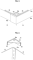
- Fig. 5 is an enlarged view of an upper end corner portion of the packing material of Example 1.
- a cap 14 as an example of a lid part is disposed at upper ends of the side plates 13.
- the cap 14 includes an apical plate 14a that covers an upper surface of the object 1 to be packed, and upper side plates 14b that extend downward from four outer peripheral sides of the apical plate 14a.
- opening portions 14c corresponding to corner members 31 to be described later are formed at corners of the apical plate 14a.
- the upper side plates 14b are disposed outside the side plates 13 in a case where the cap 14 is mounted on upper portions of the side plates 13.
- the second packing material 21 loaded on the upper side has a configuration identical to the configuration of the first packing material 11, and includes a pallet 22, side plates 23, and a cap (not shown).
- each of the corner members 31 of Example 1 includes a top plate 32 having the shape of a substantially isosceles right triangle.
- a positioning protrusion 32a as an example of a positioning portion is formed on an upper surface of the top plate 32.
- load receiving ribs 33 as an example of a load receiving portion are formed along two sides, between which a right angle is interposed, of the top plate 32 having the shape of an isosceles right triangle.
- Each of the load receiving ribs 33 is formed in the shape of a linear projection that protrudes upward and extends in a horizontal direction. As shown in Figs. 3A to 3D , the load receiving ribs 33 are formed in a substantially L-shape along the two sides of the top plate 32.
- each of the opening portions 14c of the cap 14 is formed such that the positioning protrusion 32a and the load receiving ribs 33 penetrate the apical plate 14a from below to above.
- the shape of the opening portion 14c is not limited to a shape illustrated in Fig. 5 , and can be changed to, for example, the shape of an opening through which the entire corner member 31 can pass, and the like.
- Connecting portions 34 as an example of a connector are formed on a lower surface of the top plate 32 at positions below the load receiving ribs 33.
- Groove-shaped connecting grooves 35 which are connected in a case where the upper ends of the side plates 13 are inserted into the connecting grooves 35, are formed in the connecting portions 34.
- the connecting grooves 35 of Example 1 are formed in a substantially L-shape along the load receiving ribs 33.
- each connecting groove 35 is disposed on a lower extension of each load receiving rib 33, and is adapted such that a load acts in a longitudinal direction of the side plate 13 (vertical direction) in a case where a load acts on the load receiving rib 33 from above. That is, each connecting groove 35 is adapted such that a load does not act in a direction inclined with respect to the longitudinal direction of the side plate 13.
- Fig. 6 is an enlarged view of a main portion of a corner portion of the side plates of Example 1.
- a wide portion 35b having a groove width about twice the thickness of the side plate 13 is formed near a corner 35a and a narrow portion 35c having a groove width corresponding to the thickness of the side plate 13 is formed at a position away from the corner 35a.
- the side plates may doubly overlap with and be fixed to each other at a corner portion 13a with glue, an adhesive, a stapler, or the like.
- the wide portions 35b are formed at the corner member 31 of Example 1 to correspond to the corner portion 13a.
- feet 41 as an example of mounting portions are supported at a lower portion of the pallet 12.
- Each foot 41 is fastened to the pallet 12 by screws, bolts, or the like, may be connected to the pallet 12 by a snap-fit structure, can also be fixed to the pallet 12 by an adhesive, or can also be formed integrally with the pallet 12.
- Each foot 41 includes a bottom portion 42 and a pair of side wall portions 43 and 43 that extends upward from both end portions of the bottom portion 42 in a width direction.
- a space 44 into which a fork (claw) of a forklift or a hand lifter can be inserted is formed between the side wall portions 43 and 43.
- a positioning recess 42a as an example of a portion to be positioned is formed on the bottom side of the bottom portion 42 at a position corresponding to the positioning protrusion 32a.
- the positioning recess 42a is formed of a recess having a size that allows the positioning protrusion 32a to be housed, and a pulling shape (a guide shape or an R shape) which allows the positioning protrusion 32a to be pulled inward, that is, is inclined inward toward the upper side of the recess, is formed at an inner edge portion of the positioning recess 42a.
- a load groove portion 42b as an example of a load portion is formed on the bottom side of the bottom portion 42 at positions corresponding to the load receiving ribs 33.
- the load groove portion 42b of Example 1 is formed in the shape of a recessed groove to correspond to the load receiving ribs 33 having the shape of a linear projection. Furthermore, the load groove portion 42b of Example 1 is disposed at positions below the side plates 13 in a direction of gravity, specifically, at positions on lower extensions of the side plates 13 to correspond to the load receiving ribs 33.
- Fig. 7 is an enlarged cross-sectional view of main portions of the load receiving portion and a part of the load portion of Example 1.
- the corner members 31 and the feet 41 form a loading auxiliary tool 31+41 of Example 1 that serves as an example of an auxiliary unit for assisting in loading the second packing material 21 onto the first packing material 11.
- the bottom of the pallet 12 is loaded onto the upper surface of the cap 14.
- the position of the second packing material 21 may be shifted from the position of the first packing material 11 loaded on the lower side due to an error in the operation of the forklift, or the like, a load may be received at a position shifted from the position directly above the side plates 13 of the first packing material 11.
- a position where a load received by the side plates 13 is locally increased in a circumferential direction may be generated, the side plates 13 are buckled and deformed and the second packing material 21 falls and collapses at the worst. For this reason, there is a concern that the object 1' to be packed housed in the second packing material 21 will be damaged.
- Example 1 the load of the second packing material 21 is received by the load receiving ribs 33 and the load can be caused to act on the upper side of the side plates 13. Accordingly, in a case where the first packing material 11 and the second packing material 21 are stacked one above the other, the deformation of the packing materials 11 and 21 can be suppressed.
- the corner members 31 of Example 1 are connected to the upper ends of the side plates 13 by the connecting portions 34. Accordingly, since the corner members 31 are not likely to be separated from the upper ends of the side plates 13 as compared to a case where the corner members 31 are not connected to the upper ends of the side plates 13, a load can be caused to stably act on the side plates 13 from above.
- the wide portions 35b are formed in the connecting grooves 35.
- the wide portions 35b are not provided, it is not possible to cope with a configuration in which the side plates 13 doubly overlap with each other at the corner portion 13a and there is a concern that the corner members 31 cannot be connected to the side plates 13, or the corner members 31 are deformed or receives stress and a load applied from the second packing material 21 may not stably act on the side plates 13 in a case where the side plates 13 are forcibly fitted to the corner members 31.
- the corner member 31 of Example 1 including the wide portions 35b, it is also possible to cope with a configuration in which the side plates 13 doubly overlap with each other at the corner portion 13a and to stabilize a load acting on the side plates 13. Even though the side plates 13 do not doubly overlap with each other, the corner member 31 can be connected to the upper ends of the side plates 13 by the wide portions 35b and the narrow portions 35c.
- the load groove portion 42b is formed on each foot 41 in Example 1. Even in a configuration in which the load groove portions 42b are not provided and the lower surfaces of the bottom portions 42 are flat surfaces, a load can be caused to act on the load receiving ribs 33. However, in a case where the lower surfaces of the bottom portions 42 are flat surfaces, the position of the second packing material 21 in the horizontal direction may be shifted from the position of the first packing material 11 due to an error in the operation of the forklift, or the like. For this reason, in a case where packing materials are stacked in three or four layers, there is a possibility that the packing material stacked in the upper layer will be more significantly shifted.
- Example 1 in a case where the second packing material 21 is loaded onto the first packing material 11, only the load receiving ribs 33 and the load groove portions 42b are in contact with each other and a gap is formed between the upper surface of the cap 14 that is the upper surface of the first packing material 11 and the bottom of each bottom portion 42 that is the lower surface of the second packing material 21.
- portions other than the load receiving ribs 33 and the load groove portions 42b are in contact with each other as well, there is a concern that a load obliquely acts on the side plates 13 and the buckling or the like of the side plates 13 is likely to occur.
- a load is likely to act from the upper side of the side plates 13.
- the form of the linear projection has been exemplified as the load receiving rib 33 and the form of the protrusion has also been described as a form that can be employed.
- the load receiving rib 33 is not limited thereto.
- a form in which the protrusions are arranged along the linear projection or in a specific pattern can also be employed.
- (H05) A configuration in which the corner members 31 and the cap 14 are provided separately from each other has been exemplified in the above-mentioned example, but the corner members 31 and the cap 14 can also be integrally formed. Further, a configuration in which the cap 14 is not provided can also be employed. That is, the present invention is not limited to a configuration in which a total of four corner members 31 are disposed at the corners, and the four corner members 31 can also be integrally molded into one member and the integrally molded member can also be formed in a shape that allows the integrally molded member to be inserted into the entire upper portion of each of the packing materials 11 and 21. Moreover, a configuration in which a corner member is formed in a substantially U-shape to cover two corners and one side interposed between the two corners and two corner members are installed to face each other can also be employed.
- the feet 41 and the pallet 12 can also be provided separately from each other or can also be integrally molded. Moreover, a form in which a portion corresponding to a quarter of the pallet is integrally formed on an upper surface of one foot and four feet are arranged and assembled to form a configuration identical to the configuration of the feet and the pallet can also be employed.
- packing materials 11 and 21 have identical dimensions in an X-axis direction and a Y-axis direction, that is, upper and lower packing materials have different heights but have an identical horizontal cross-sectional shape in the above-mentioned example, packing materials having different heights can also be stacked since a relationship between the feet 41 and the corner members 31 is identical to the above-mentioned relationship.
- the deformation of packing materials stacked one above the other can be suppressed as compared to a case where a load is received at a position shifted from the upper portion of the side surface of the packing material.
- the load of the second packing material can be caused to act on the upper ends of the side surfaces of the first packing material from above, damaged to the first packing material is suppressed as compared to a case where a load acts from the lateral side of the side surfaces of the first packing material.
- connection between the load receiving portion and the side surfaces is stable as compared to a case where the upper ends of the side surfaces are not inserted, a load acting on the side surfaces can be stabilized.
- the auxiliary unit of (((4))) can be connected even in a case where the thickness directions of the side surfaces overlap with each other.
- the load of the second packing material can be caused to act on the load portion from the upper side of the side surfaces of the first packing material.
- the auxiliary unit of (((6))) since a load can be caused to act on the side surfaces only from above as compared to a case where not only the load portion and the load receiving portion are in contact with each other, the deformation of the side surfaces can be suppressed.
- auxiliary unit of (((7))) damaged to the load portion can be suppressed as compared to a case where the load portion is formed to be convex downward.
- the concentration of a load can be suppressed.
- the load portion can be operated integrally with the support part.
Landscapes
- Engineering & Computer Science (AREA)
- Mechanical Engineering (AREA)
- Packaging Of Machine Parts And Wound Products (AREA)
- Buffer Packaging (AREA)
- Stackable Containers (AREA)
- Pallets (AREA)
Abstract
An auxiliary unit (31, 41), which is disposed between a first packing material including a plurality of side surfaces (13) and a second packing material loaded onto the first packing material in a direction of gravity and assists in loading the second packing material onto the first packing material, includes a load receiving portion that is provided along the side surfaces of the first packing material on an upper side in a direction of gravity and receives a load of the second packing material.
Description
- The present invention relates to an auxiliary unit.
- With regard to a packing material that is used to pack an object to be packed, techniques disclosed in
JP2003-081272A Figs. 1 and2 ),JP2011-111206A Figs. 1 ,2 ,4 , and6 ), andJP2006-232297A Figs. 1 to 4 ) are publicly known in the related art. -
JP2003-081272A Figs. 1 and2 ) discloses a configuration in which four protrusions (5) are installed on an upper surface of a base (1), a plurality of honeycomb structures (20) are placed on upper surfaces of the protrusions (5), a lateral frame body (2) surrounding the honeycomb structures (20) is stacked on the base (1), and a base (1) serving as a lid is stacked on the uppermost frame body (2) with regard to packing boxes that can be stacked in multiple layers. -
JP2011-111206A Figs. 1 ,2 ,4 , and6 ) discloses a technique in which protruding portions (8) are provided on an upper surface of a lid body (A3) of a packing container and the protruding portions (8) are fitted to recesses (7) formed on a lower surface of a tray (A2) with a pallet provided at the bottom of the packing container to make it difficult for the position of the packing container to be shifted in a case where the packing containers are stacked in layers. -
JP2006-232297A Figs. 1 to 4 ) discloses a technique in which protruding portions (4a to 4c) of a cardboard case are fitted to cut-out holes (102a) of a cardboard pallet (100) to position the cardboard case and to suppress the skidding and collapse of the cardboard case in a case where the cardboard pallet (100) is loaded onto the cardboard case (1) and the cardboard case (1) is stacked on the cardboard pallet (100). - A technical object of the present invention is to suppress the deformation of packing materials stacked one above the other as compared to a case where a load is received at a position shifted from an upper portion of a side surface of the packing material.
- According to a first aspect of the present disclosure, there is provided an auxiliary unit that is disposed between a first packing material including a plurality of side surfaces and a second packing material loaded onto the first packing material in a direction of gravity and assists in loading the second packing material onto the first packing material, the auxiliary unit including a load receiving portion that is provided along the side surfaces of the first packing material on an upper side in a direction of gravity and receives a load of the second packing material.
- According to a second aspect of the present disclosure, in the auxiliary unit according to the first aspect, the load receiving portion may be disposed at upper ends of the side surfaces of the first packing material.
- According to a third aspect of the present disclosure, in the auxiliary unit according to the second aspect, the load receiving portion may be disposed above a groove-shaped connector that is connected in a case where the upper ends of the side surfaces of the first packing material are inserted into the connector.
- According to a fourth aspect of the present disclosure, in the auxiliary unit according to the third aspect, a groove width of the connector may be partially increased to correspond to a portion where thickness directions of the side surfaces of the first packing material overlap with each other.
- According to a fifth aspect of the present disclosure, in the auxiliary unit according to any one of the first to fourth aspects, the second packing material may include a plurality of side surfaces, and the auxiliary unit may include a load portion that is provided along the side surfaces of the second packing material on a lower side in a direction of gravity and is in contact with the load receiving portion.
- According to a sixth aspect of the present disclosure, in the auxiliary unit according to the fifth aspect, in a case where the second packing material is loaded onto the first packing material, only the load portion and the load receiving portion may be in contact with each other and a gap may be formed between an upper portion of the first packing material and a lower portion of the second packing material.
- According to a seventh aspect of the present disclosure, in the auxiliary unit according to the fifth or sixth aspect, the load receiving portion may protrude upward, and the load portion may be recessed upward.
- According to an eighth aspect of the present disclosure, in the auxiliary unit according to the seventh aspect, the load receiving portion may be formed in a shape of a linear projection extending in a horizontal direction, and the load portion may be formed in a shape of a groove to which the load receiving portion is fitted.
- According to a ninth aspect of the present disclosure, in the auxiliary unit according to any one of the fifth to eighth aspects, the load portion may be formed integrally with a support part that supports the second packing material on an upper surface thereof.
- According to the first aspect, the deformation of packing materials stacked one above the other can be suppressed as compared to a case where a load is received at a position shifted from the upper portion of the side surface of the packing material.
- According to the second aspect, since the load of the second packing material can be caused to act on the upper ends of the side surfaces of the first packing material from above, damaged to the first packing material is suppressed as compared to a case where a load acts from the lateral side of the side surfaces of the first packing material.
- According to the third aspect, since connection between the load receiving portion and the side surfaces is stable as compared to a case where the upper ends of the side surfaces are not inserted, a load acting on the side surfaces can be stabilized.
- According to the fourth aspect, the auxiliary unit can be connected even in a case where the thickness directions of the side surfaces overlap with each other.
- According to the fifth aspect, the load of the second packing material can be caused to act on the load portion from the upper side of the side surfaces of the first packing material.
- According to the sixth aspect, since a load can be caused to act on the side surfaces only from above as compared to a case where not only the load portion and the load receiving portion are in contact with each other, the deformation of the side surfaces can be suppressed.
- According to the seventh aspect, damaged to the load portion can be suppressed as compared to a case where the load portion is formed to be convex downward.
- According to the eighth aspect, since a range in which a load is received can be widened as compared to a case where the load receiving portion is not formed in the shape of a linear projection, the concentration of a load can be suppressed.
- According to the ninth aspect, the load portion can be operated integrally with the support part.
- Exemplary embodiment(s) of the present invention will be described in detail based on the following figures, wherein:
-
Fig. 1 is an overall view of a packing material including an auxiliary unit of Example 1; -
Fig. 2 is an exploded view of the packing material shown inFig. 1 ; -
Figs. 3A to 3D are diagrams illustrating a load receiving portion of Example 1,Fig. 3A is a perspective view,Fig. 3B is a diagram (top view) viewed in a direction of an arrow IIIB shown inFig. 3A, Fig. 3C is a diagram (bottom view) viewed in a direction of an arrow IIIC shown inFig. 3A, and Fig. 3D is a diagram viewed in a direction of an arrow IIID shown inFig. 3A ; -
Figs. 4A and 4B are diagrams illustrating a load portion of Example 1,Fig. 4A is a perspective view, andFig. 4B is a diagram (bottom view) viewed in a direction of an arrow IVB shown inFig. 4A ; -
Fig. 5 is an enlarged view of an upper end corner portion of the packing material of Example 1; -
Fig. 6 is an enlarged view of a main portion of a corner portion of side plates of Example 1; and -
Fig. 7 is an enlarged cross-sectional view of main portions of the load receiving portion and a part of the load portion of Example 1. - Example as a specific example of an exemplary embodiment of the present invention will be described below with reference to the drawings, but the present invention is not limited to the following example.
- In the following description using the drawings, members other than members required for description will be appropriately omitted for the sake of easy understanding.
-
Fig. 1 is an overall view of a packing material including an auxiliary unit of Example 1. -
Fig. 2 is an exploded view of the packing material shown inFig. 1 . -
Figs. 3A to 3D are diagrams illustrating a load receiving portion of Example 1,Fig. 3A is a perspective view,Fig. 3B is a diagram (top view) viewed in a direction of an arrow IIIB shown inFig. 3A, Fig. 3C is a diagram (bottom view) viewed in a direction of an arrow IIIC shown inFig. 3A, and Fig. 3D is a diagram viewed in a direction of an arrow IIID shown inFig. 3A . -
Figs. 4A and 4B are diagrams illustrating a load portion of Example 1,Fig. 4A is a perspective view, andFig. 4B is a diagram (bottom view) viewed in a direction of an arrow IVB shown inFig. 4A . - In
Fig. 1 , in a case where packing materials are stored in a warehouse, asecond packing material 21 in which an object 1' to be packed is housed may be loaded onto afirst packing material 11 in which anobject 1 to be packed is housed. Arbitrary objects can be applied as theobjects 1 and 1' to be packed. For example, arbitrary objects to be packed, such as industrial products, such as a computer device, a printer, and a copy machine, home appliances, such as a television, a refrigerator, and a microwave oven, food, and processed goods, can be applied. - In
Figs. 1 and2 , thefirst packing material 11 disposed on the lower side includes apallet 12 as an example of a support part which theobject 1 to be packed is loaded onto an upper surface thereof. Thepallet 12 of Example 1 is made of, for example, a resin material. However, thepallet 12 is not limited thereto and can also be made of wood or a metal material. -
Side plates 13 surrounding the outer periphery of sides of theobject 1 to be packed are disposed at an outer edge portion of thepallet 12 as an example of side surfaces of the packing material. Theside plate 13 of Example 1 is made of, for example, a cardboard as a paper material, but are not limited thereto. However, theside plate 13 can be made of an arbitrary material, such as a resin material, wood, or a metal material. -
Fig. 5 is an enlarged view of an upper end corner portion of the packing material of Example 1. - A
cap 14 as an example of a lid part is disposed at upper ends of theside plates 13. Thecap 14 includes anapical plate 14a that covers an upper surface of theobject 1 to be packed, andupper side plates 14b that extend downward from four outer peripheral sides of theapical plate 14a. InFigs. 2 and5 , openingportions 14c corresponding to cornermembers 31 to be described later are formed at corners of theapical plate 14a. Theupper side plates 14b are disposed outside theside plates 13 in a case where thecap 14 is mounted on upper portions of theside plates 13. - The
second packing material 21 loaded on the upper side has a configuration identical to the configuration of thefirst packing material 11, and includes apallet 22,side plates 23, and a cap (not shown). - In
Fig. 2 ,corner members 31 as an example of receiving parts are disposed at corners of upper end portions of theside plates 13. InFigs. 2 and3 , each of thecorner members 31 of Example 1 includes atop plate 32 having the shape of a substantially isosceles right triangle. Apositioning protrusion 32a as an example of a positioning portion is formed on an upper surface of thetop plate 32. - On the upper surface of the
top plate 32,load receiving ribs 33 as an example of a load receiving portion are formed along two sides, between which a right angle is interposed, of thetop plate 32 having the shape of an isosceles right triangle. Each of theload receiving ribs 33 is formed in the shape of a linear projection that protrudes upward and extends in a horizontal direction. As shown inFigs. 3A to 3D , theload receiving ribs 33 are formed in a substantially L-shape along the two sides of thetop plate 32. - In
Fig. 5 , each of the openingportions 14c of thecap 14 is formed such that thepositioning protrusion 32a and theload receiving ribs 33 penetrate theapical plate 14a from below to above. The shape of theopening portion 14c is not limited to a shape illustrated inFig. 5 , and can be changed to, for example, the shape of an opening through which theentire corner member 31 can pass, and the like. - Connecting
portions 34 as an example of a connector are formed on a lower surface of thetop plate 32 at positions below theload receiving ribs 33. Groove-shaped connectinggrooves 35, which are connected in a case where the upper ends of theside plates 13 are inserted into the connectinggrooves 35, are formed in the connectingportions 34. InFig. 3C , the connectinggrooves 35 of Example 1 are formed in a substantially L-shape along theload receiving ribs 33. InFig. 3D , each connectinggroove 35 is disposed on a lower extension of eachload receiving rib 33, and is adapted such that a load acts in a longitudinal direction of the side plate 13 (vertical direction) in a case where a load acts on theload receiving rib 33 from above. That is, each connectinggroove 35 is adapted such that a load does not act in a direction inclined with respect to the longitudinal direction of theside plate 13. -
Fig. 6 is an enlarged view of a main portion of a corner portion of the side plates of Example 1. - In
Fig. 3C , in the connectinggroove 35 of Example 1, awide portion 35b having a groove width about twice the thickness of theside plate 13 is formed near acorner 35a and anarrow portion 35c having a groove width corresponding to the thickness of theside plate 13 is formed at a position away from thecorner 35a. - As shown in
Fig. 6 , depending on the configuration of theside plates 13, the side plates may doubly overlap with and be fixed to each other at acorner portion 13a with glue, an adhesive, a stapler, or the like. Thewide portions 35b are formed at thecorner member 31 of Example 1 to correspond to thecorner portion 13a. - In
Figs. 1 ,2 , and4 ,feet 41 as an example of mounting portions are supported at a lower portion of thepallet 12. Eachfoot 41 is fastened to thepallet 12 by screws, bolts, or the like, may be connected to thepallet 12 by a snap-fit structure, can also be fixed to thepallet 12 by an adhesive, or can also be formed integrally with thepallet 12. - Each
foot 41 includes abottom portion 42 and a pair ofside wall portions bottom portion 42 in a width direction. Aspace 44 into which a fork (claw) of a forklift or a hand lifter can be inserted is formed between theside wall portions - A
positioning recess 42a as an example of a portion to be positioned is formed on the bottom side of thebottom portion 42 at a position corresponding to thepositioning protrusion 32a. Thepositioning recess 42a is formed of a recess having a size that allows thepositioning protrusion 32a to be housed, and a pulling shape (a guide shape or an R shape) which allows thepositioning protrusion 32a to be pulled inward, that is, is inclined inward toward the upper side of the recess, is formed at an inner edge portion of thepositioning recess 42a. - Further, a
load groove portion 42b as an example of a load portion is formed on the bottom side of thebottom portion 42 at positions corresponding to theload receiving ribs 33. Theload groove portion 42b of Example 1 is formed in the shape of a recessed groove to correspond to theload receiving ribs 33 having the shape of a linear projection. Furthermore, theload groove portion 42b of Example 1 is disposed at positions below theside plates 13 in a direction of gravity, specifically, at positions on lower extensions of theside plates 13 to correspond to theload receiving ribs 33. -
Fig. 7 is an enlarged cross-sectional view of main portions of the load receiving portion and a part of the load portion of Example 1. - In
Fig. 7 , in Example 1, a depth L1 of a groove of theload groove portion 42b is smaller than a height L2 of a protrusion of theload receiving rib 33. Further, in Example 1, a depth L3 of a recess of thepositioning recess 42a from a bottom of the groove of theload groove portion 42b is larger than a height L4 of thepositioning protrusion 32a from a distal end of the protrusion of theload receiving rib 33. - Accordingly, in Example 1, in a state where the
second packing material 21 is loaded onto thefirst packing material 11, theload receiving ribs 33 are in contact with theload groove portions 42b, upper ends of thepositioning protrusions 32a are not in contact with the bottoms of the recesses of the positioning recesses 42a, and the bottoms of thebottom portions 42 of thefeet 41 are also not in contact with the upper surface of thecap 14. Therefore, in Example 1, in a case where thesecond packing material 21 is loaded onto thefirst packing material 11, only theload receiving ribs 33 and theload groove portions 42b are in contact with each other and agap 51 is formed between the upper surface of thecap 14 that is the upper surface of thefirst packing material 11 and the bottom of eachbottom portion 42 that is the lower surface of thesecond packing material 21. - The
corner members 31 and thefeet 41 form a loadingauxiliary tool 31+41 of Example 1 that serves as an example of an auxiliary unit for assisting in loading thesecond packing material 21 onto thefirst packing material 11. - In the loading
auxiliary tool 31+41 of Example 1 having the above-mentioned configuration, a load applied from above acts on theload receiving ribs 33 in a case where thesecond packing material 21 is loaded onto thefirst packing material 11. Here, since theload receiving ribs 33 are disposed above theside plate 13 in the direction of gravity, a load acting on theload receiving ribs 33 acts on theside plates 13 in the direction of gravity in which theside plates 13 extend. That is, the load of thesecond packing material 21 acts directly above theside plates 13. - In a configuration in the related art not including the loading
auxiliary tool 31+41, the bottom of thepallet 12 is loaded onto the upper surface of thecap 14. In this case, since the position of thesecond packing material 21 may be shifted from the position of thefirst packing material 11 loaded on the lower side due to an error in the operation of the forklift, or the like, a load may be received at a position shifted from the position directly above theside plates 13 of thefirst packing material 11. In this case, since a position where a load received by theside plates 13 is locally increased in a circumferential direction may be generated, theside plates 13 are buckled and deformed and thesecond packing material 21 falls and collapses at the worst. For this reason, there is a concern that the object 1' to be packed housed in thesecond packing material 21 will be damaged. - Further, in the configurations disclosed in
JP2003-081272A Figs. 1 and2 ),JP2011-111206A Figs. 1 ,2 ,4 , and6 ), andJP2006-232297A Figs. 1 to 4 ), an object loaded on the upper side is aligned to reduce a shift but a load is received by a portion corresponding to a lid. Accordingly, in a case where a load acts on the inside of a lid in a plane direction (the inside of a portion corresponding to theside plates 13 provided on the outside), a force pushing theside plate 13 to the outside in the plane direction, that is, a force in a direction in which theside plate 13 expand is likely to act. Therefore, since a force for bending theside plate 13 in a thickness direction acts, there is a problem that theside plate 13 is likely to be deformed, buckled, or damaged as compared to a case where a force in the direction of gravity, which is a length direction of theside plate 13, acts. - On the other hand, in Example 1, the load of the
second packing material 21 is received by theload receiving ribs 33 and the load can be caused to act on the upper side of theside plates 13. Accordingly, in a case where thefirst packing material 11 and thesecond packing material 21 are stacked one above the other, the deformation of the packingmaterials - Further, the
corner members 31 of Example 1 are connected to the upper ends of theside plates 13 by the connectingportions 34. Accordingly, since thecorner members 31 are not likely to be separated from the upper ends of theside plates 13 as compared to a case where thecorner members 31 are not connected to the upper ends of theside plates 13, a load can be caused to stably act on theside plates 13 from above. - In particular, since the
side plates 13 are connected to the connectingportions 34 in the form of being inserted in Example 1, an adhesive or the like and screws or the like are not used. Accordingly, connecting work and detaching work can also be easily performed. Furthermore, reuse or recycling are also easy as compared to a case where theside plate 13 made of a cardboard and thecorner member 31 made of a resin are connected to each other by an adhesive. - Further, in the
corner member 31 of Example 1, thewide portions 35b are formed in the connectinggrooves 35. In a configuration in which thewide portions 35b are not provided, it is not possible to cope with a configuration in which theside plates 13 doubly overlap with each other at thecorner portion 13a and there is a concern that thecorner members 31 cannot be connected to theside plates 13, or thecorner members 31 are deformed or receives stress and a load applied from thesecond packing material 21 may not stably act on theside plates 13 in a case where theside plates 13 are forcibly fitted to thecorner members 31. In the case of thecorner member 31 of Example 1 including thewide portions 35b, it is also possible to cope with a configuration in which theside plates 13 doubly overlap with each other at thecorner portion 13a and to stabilize a load acting on theside plates 13. Even though theside plates 13 do not doubly overlap with each other, thecorner member 31 can be connected to the upper ends of theside plates 13 by thewide portions 35b and thenarrow portions 35c. - In addition, the
load groove portion 42b is formed on eachfoot 41 in Example 1. Even in a configuration in which theload groove portions 42b are not provided and the lower surfaces of thebottom portions 42 are flat surfaces, a load can be caused to act on theload receiving ribs 33. However, in a case where the lower surfaces of thebottom portions 42 are flat surfaces, the position of thesecond packing material 21 in the horizontal direction may be shifted from the position of thefirst packing material 11 due to an error in the operation of the forklift, or the like. For this reason, in a case where packing materials are stacked in three or four layers, there is a possibility that the packing material stacked in the upper layer will be more significantly shifted. In a case where the packing material is significantly shifted, there is also a concern that a load received by theload receiving ribs 33 will be non-uniform or unbalanced between the fourcorner members 31. Since theload receiving ribs 33 are fitted to theload groove portions 42b in Example 1, the position of thesecond packing material 21 in the horizontal direction is likely to be stable and the occurrence of the unbalance of a load is also suppressed. - In particular, since the
positioning protrusions 32a and the positioning recesses 42a are also provided in Example 1, the shift of the position of thesecond packing material 21 from the position of thefirst packing material 11 is likely to be suppressed. In a configuration in which thepositioning protrusions 32a and the positioning recesses 42a are not provided, the delicate operation of the forklift may be required to align theload receiving ribs 33 with theload groove portions 42b. However, in Example 1 in which thepositioning protrusions 32a and the positioning recesses 42a are provided, the positions of theload receiving ribs 33 and the positions of theload groove portions 42b are easily aligned in a case where the positions of thepositioning protrusions 32a are aligned with the positions of the positioning recesses 42a. - Further, in Example 1, in a case where the
second packing material 21 is loaded onto thefirst packing material 11, only theload receiving ribs 33 and theload groove portions 42b are in contact with each other and a gap is formed between the upper surface of thecap 14 that is the upper surface of thefirst packing material 11 and the bottom of eachbottom portion 42 that is the lower surface of thesecond packing material 21. In a case where portions other than theload receiving ribs 33 and theload groove portions 42b are in contact with each other as well, there is a concern that a load obliquely acts on theside plates 13 and the buckling or the like of theside plates 13 is likely to occur. However, since only theload receiving ribs 33 and theload groove portion 42b are in contact with each other in Example 1, a load is likely to act from the upper side of theside plates 13. - Furthermore, in Example 1, the
load receiving ribs 33 protrude upward and theload groove portion 42b are formed to be recessed upward. Theload receiving ribs 33 may be formed in a concave shape and theload groove portion 42b may be formed in a convex shape. However, since thefirst packing material 11 is in contact with the floor via not the bottoms of thefeet 41 but only the convex load groove portions in a case where the convex load groove portions are provided and thefirst packing material 11 is placed on a flat floor, the convex load groove portions are likely to be damaged. In a case where the concaveload groove portions 42b are provided as in Example 1, the bottoms of thebottom portions 42 of thefeet 41 are in contact with the floor. Accordingly, damage to theload groove portions 42b is suppressed as compared to a case where the convex load groove portions are provided. - Further, in Example 1, the
load receiving rib 33 is formed in the shape of a linear projection extending in a linear direction, and theload groove portion 42b is also formed in the shape of a groove. The shape of theload receiving rib 33 is not limited to the shape of a linear projection, and may be the shape of a protrusion, such as thepositioning protrusion 32a. Since the linear projection as shown in Example 1 has a contact area larger than the contact area of the protrusion, the concentration of a load is reduced. As a result, the concentrated load is also less likely to act on theside plates 13. - The example of the present invention has been described in detail above, but the present invention is not limited to the above-mentioned example and can have various modifications without departing from the scope of the present invention described in claims. Modification examples (H01) to (H08) of the present invention will be exemplified below.
- (H01) In the above-mentioned example, the form of the linear projection has been exemplified as the
load receiving rib 33 and the form of the protrusion has also been described as a form that can be employed. However, theload receiving rib 33 is not limited thereto. A form in which the protrusions are arranged along the linear projection or in a specific pattern can also be employed. - (H02) It is desirable that the
positioning protrusions 32a and the positioning recesses 42a are provided in the above-mentioned example, but thepositioning protrusions 32a and the positioning recesses 42a may not be provided. - (H03) A configuration in which four
corner members 31 having an identical configuration and fourfeet 41 having an identical configuration are disposed has been exemplified in the above-mentioned example, but the present invention is not limited thereto. For example, the numbers of thecorner members 31 andfeet 41 each including thepositioning protrusion 32a and thepositioning recess 42a can be set to one to three, and corner members and feet not including thepositioning protrusion 32a and thepositioning recess 42a can be provided as theother corner members 31 and theother feet 41. Moreover, a configuration in which thecorner members 31 are installed at all the four corners has been exemplified in Example 1, but the present invention is not limited thereto and a configuration in which thecorner members 31 are provided at two corners facing each other can also be employed. - (H04) A form in which the
wide portions 35b are provided has been exemplified in the above-mentioned example, but the present invention is not limited thereto. In a case where there is no overlapping portion on theside plates 13, a form in which thewide portions 35b are not provided can also be employed. Further, for example, in a case where there is an overlapping portion at only one position on theside plates 13 in a circumferential direction, a modification in which only onecorner member 31 including thewide portions 35b is provided and corner members not including the wide portions are used as the other corner members can also be employed. - (H05) A configuration in which the
corner members 31 and thecap 14 are provided separately from each other has been exemplified in the above-mentioned example, but thecorner members 31 and thecap 14 can also be integrally formed. Further, a configuration in which thecap 14 is not provided can also be employed. That is, the present invention is not limited to a configuration in which a total of fourcorner members 31 are disposed at the corners, and the fourcorner members 31 can also be integrally molded into one member and the integrally molded member can also be formed in a shape that allows the integrally molded member to be inserted into the entire upper portion of each of the packingmaterials - (H06) In the above-mentioned example, it has been described above that the
feet 41 and thepallet 12 can also be provided separately from each other or can also be integrally molded. Moreover, a form in which a portion corresponding to a quarter of the pallet is integrally formed on an upper surface of one foot and four feet are arranged and assembled to form a configuration identical to the configuration of the feet and the pallet can also be employed. - (H07) In a case where the packing
materials feet 41 and thecorner members 31 is identical to the above-mentioned relationship. - (H08) A case where the packing
materials materials -
- ((((1)))) An auxiliary unit that is disposed between a first packing material including a plurality of side surfaces and a second packing material loaded onto the first packing material in a direction of gravity and assists in loading the second packing material onto the first packing material, the auxiliary unit comprising:
a load receiving portion that is provided along the side surfaces of the first packing material on an upper side in a direction of gravity and receives a load of the second packing material. - (((2))) The auxiliary unit according to (((1))),
wherein the load receiving portion is disposed at upper ends of the side surfaces of the first packing material. - ((((3)))) The auxiliary unit according to (((2))),
wherein the load receiving portion is disposed above a groove-shaped connector that is connected in a case where the upper ends of the side surfaces of the first packing material are inserted into the connector. - ((((4)))) The auxiliary unit according to (((3))),
wherein a groove width of the connector is partially increased to correspond to a portion where thickness directions of the side surfaces of the first packing material overlap with each other. - ((((5)))) The auxiliary unit according to any one of (((1))) to (((4))),
wherein the second packing material includes a plurality of side surfaces, and the auxiliary unit includes a load portion that is provided along the side surfaces of the second packing material on a lower side in a direction of gravity and is in contact with the load receiving portion. - (((6))) The auxiliary unit according to (((5))),
wherein in a case where the second packing material is loaded onto the first packing material, only the load portion and the load receiving portion are in contact with each other and a gap is formed between an upper portion of the first packing material and a lower portion of the second packing material. - (((7))) The auxiliary unit according to (((5))) or (((6))),
- wherein the load receiving portion protrudes upward, and
- the load portion is recessed upward.
- ((((8)))) The auxiliary unit according to (((7))),
- wherein the load receiving portion is formed in a shape of a linear projection extending in a horizontal direction, and
- the load portion is formed in a shape of a groove to which the load receiving portion is fitted.
- ((((9)))) The auxiliary unit according to any one of (((5))) to (((8))),
wherein the load portion is formed integrally with a support part that supports the second packing material on an upper surface thereof. - According to the auxiliary unit of (((1))), the deformation of packing materials stacked one above the other can be suppressed as compared to a case where a load is received at a position shifted from the upper portion of the side surface of the packing material.
- According to the auxiliary unit of (((2))), since the load of the second packing material can be caused to act on the upper ends of the side surfaces of the first packing material from above, damaged to the first packing material is suppressed as compared to a case where a load acts from the lateral side of the side surfaces of the first packing material.
- According to the auxiliary unit of (((3))), since connection between the load receiving portion and the side surfaces is stable as compared to a case where the upper ends of the side surfaces are not inserted, a load acting on the side surfaces can be stabilized.
- According to the auxiliary unit of (((4))), the auxiliary unit can be connected even in a case where the thickness directions of the side surfaces overlap with each other.
- According to the auxiliary unit of (((5))), the load of the second packing material can be caused to act on the load portion from the upper side of the side surfaces of the first packing material.
- According to the auxiliary unit of (((6))), since a load can be caused to act on the side surfaces only from above as compared to a case where not only the load portion and the load receiving portion are in contact with each other, the deformation of the side surfaces can be suppressed.
- According to the auxiliary unit of (((7))), damaged to the load portion can be suppressed as compared to a case where the load portion is formed to be convex downward.
- According to the auxiliary unit of (((8))), since a range in which a load is received can be widened as compared to a case where the load receiving portion is not formed in the shape of a linear projection, the concentration of a load can be suppressed.
- According to the auxiliary unit of (((9))), the load portion can be operated integrally with the support part.
- The foregoing description of the exemplary embodiments of the present invention has been provided for the purposes of illustration and description. It is not intended to be exhaustive or to limit the invention to the precise forms disclosed. Obviously, many modifications and variations will be apparent to practitioners skilled in the art. The embodiments were chosen and described in order to best explain the principles of the invention and its practical applications, thereby enabling others skilled in the art to understand the invention for various embodiments and with the various modifications as are suited to the particular use contemplated. It is intended that the scope of the invention be defined by the following claims and their equivalents.
-
- 11: first packing material
- 13: side plate of first packing material
- 21: second packing material
- 23: side plate of second packing material
- 31+41: loading auxiliary tool
- 33: load receiving rib
- 34: connecting portion
- 42b: load groove portion
Claims (9)
- An auxiliary unit that is disposed between a first packing material including a plurality of side surfaces and a second packing material loaded onto the first packing material in a direction of gravity and assists in loading the second packing material onto the first packing material, the auxiliary unit comprising:
a load receiving portion that is provided along the side surfaces of the first packing material on an upper side in a direction of gravity and receives a load of the second packing material. - The auxiliary unit according to claim 1,
wherein the load receiving portion is disposed at upper ends of the side surfaces of the first packing material. - The auxiliary unit according to claim 2,
wherein the load receiving portion is disposed above a groove-shaped connector that is connected in a case where the upper ends of the side surfaces of the first packing material are inserted into the connector. - The auxiliary unit according to claim 3,
wherein a groove width of the connector is partially increased to correspond to a portion where thickness directions of the side surfaces of the first packing material overlap with each other. - The auxiliary unit according to any one of claims 1 to 4,
wherein the second packing material includes a plurality of side surfaces, and the auxiliary unit includes a load portion that is provided along the side surfaces of the second packing material on a lower side in a direction of gravity and is in contact with the load receiving portion. - The auxiliary unit according to claim 5,
wherein in a case where the second packing material is loaded onto the first packing material, only the load portion and the load receiving portion are in contact with each other and a gap is formed between an upper portion of the first packing material and a lower portion of the second packing material. - The auxiliary unit according to claim 5 or 6,
wherein the load receiving portion protrudes upward, and
the load portion is recessed upward. - The auxiliary unit according to claim 7,wherein the load receiving portion is formed in a shape of a linear projection extending in a horizontal direction, andthe load portion is formed in a shape of a groove to which the load receiving portion is fitted.
- The auxiliary unit according to any one of claims 5 to 8,
wherein the load portion is formed integrally with a support part that supports the second packing material on an upper surface thereof.
Applications Claiming Priority (1)
| Application Number | Priority Date | Filing Date | Title |
|---|---|---|---|
| JP2023046884A JP2024135956A (en) | 2023-03-23 | 2023-03-23 | Supportive measures |
Publications (1)
| Publication Number | Publication Date |
|---|---|
| EP4434909A1 true EP4434909A1 (en) | 2024-09-25 |
Family
ID=87419141
Family Applications (1)
| Application Number | Title | Priority Date | Filing Date |
|---|---|---|---|
| EP23186045.3A Pending EP4434909A1 (en) | 2023-03-23 | 2023-07-18 | Auxiliary unit for stacking packaging material |
Country Status (4)
| Country | Link |
|---|---|
| US (1) | US20240317457A1 (en) |
| EP (1) | EP4434909A1 (en) |
| JP (1) | JP2024135956A (en) |
| CN (1) | CN118683858A (en) |
Families Citing this family (1)
| Publication number | Priority date | Publication date | Assignee | Title |
|---|---|---|---|---|
| US12515847B2 (en) * | 2023-10-24 | 2026-01-06 | Shuert Technology, Llc | Palletized container assembly with multi-purpose adapter |
Citations (9)
| Publication number | Priority date | Publication date | Assignee | Title |
|---|---|---|---|---|
| US2738891A (en) * | 1953-03-02 | 1956-03-20 | Ball Brothers Co Inc | Stackable jars |
| GB2037709A (en) * | 1978-09-14 | 1980-07-16 | Waterman D R | Stackable containers |
| JP2003081272A (en) | 2001-09-11 | 2003-03-19 | Ngk Insulators Ltd | Packaging box |
| GB2389842A (en) * | 2002-06-20 | 2003-12-24 | Andrew Hawke | Device for aligning and securing stacked boxes or containers |
| JP2006232297A (en) | 2005-02-23 | 2006-09-07 | Kyocera Mita Corp | Packaging case with pallet non-slip mechanism |
| JP2011111206A (en) | 2009-11-30 | 2011-06-09 | Honda Motor Co Ltd | Packing container |
| US20140021090A1 (en) * | 2010-10-21 | 2014-01-23 | Groupe Dusogat | Corner bead for receiving walls of a body shell and collapsible body shell that can be assembled and taken apart |
| EP2918510A1 (en) * | 2014-03-12 | 2015-09-16 | Nefab Ab | An edge fitting to support and protect a cargo casing |
| US11014702B1 (en) * | 2018-07-23 | 2021-05-25 | Eco-Latch Systems, LLC | Device holding box flaps open and down, and allowing for secure box stacking |
-
2023
- 2023-03-23 JP JP2023046884A patent/JP2024135956A/en active Pending
- 2023-07-18 EP EP23186045.3A patent/EP4434909A1/en active Pending
- 2023-07-19 US US18/354,661 patent/US20240317457A1/en active Pending
- 2023-07-19 CN CN202310885750.0A patent/CN118683858A/en active Pending
Patent Citations (9)
| Publication number | Priority date | Publication date | Assignee | Title |
|---|---|---|---|---|
| US2738891A (en) * | 1953-03-02 | 1956-03-20 | Ball Brothers Co Inc | Stackable jars |
| GB2037709A (en) * | 1978-09-14 | 1980-07-16 | Waterman D R | Stackable containers |
| JP2003081272A (en) | 2001-09-11 | 2003-03-19 | Ngk Insulators Ltd | Packaging box |
| GB2389842A (en) * | 2002-06-20 | 2003-12-24 | Andrew Hawke | Device for aligning and securing stacked boxes or containers |
| JP2006232297A (en) | 2005-02-23 | 2006-09-07 | Kyocera Mita Corp | Packaging case with pallet non-slip mechanism |
| JP2011111206A (en) | 2009-11-30 | 2011-06-09 | Honda Motor Co Ltd | Packing container |
| US20140021090A1 (en) * | 2010-10-21 | 2014-01-23 | Groupe Dusogat | Corner bead for receiving walls of a body shell and collapsible body shell that can be assembled and taken apart |
| EP2918510A1 (en) * | 2014-03-12 | 2015-09-16 | Nefab Ab | An edge fitting to support and protect a cargo casing |
| US11014702B1 (en) * | 2018-07-23 | 2021-05-25 | Eco-Latch Systems, LLC | Device holding box flaps open and down, and allowing for secure box stacking |
Also Published As
| Publication number | Publication date |
|---|---|
| US20240317457A1 (en) | 2024-09-26 |
| JP2024135956A (en) | 2024-10-04 |
| CN118683858A (en) | 2024-09-24 |
Similar Documents
| Publication | Publication Date | Title |
|---|---|---|
| JP5445855B2 (en) | Packing equipment | |
| US20240317457A1 (en) | Auxiliary unit | |
| US6311842B1 (en) | Packaging methods and products | |
| US9731861B2 (en) | Base assembly with reinforcing support panels and blanks for forming the same | |
| EP2999638B1 (en) | Shipping container | |
| EP0289363B1 (en) | Package | |
| CN107922100A (en) | Packing device | |
| US10858150B2 (en) | Securing device | |
| KR20220085039A (en) | Transport type package box | |
| JP5286592B2 (en) | Packaging equipment | |
| CN110775440A (en) | Packaging member | |
| JP2025003308A (en) | Packaging Materials | |
| KR101476636B1 (en) | Assembling method for Reinforcement integral-type package box | |
| KR102021387B1 (en) | Corner unit for packing box | |
| JP4863724B2 (en) | Pallet packing box and pallet with packing box | |
| KR101574610B1 (en) | cover for packing boxes | |
| EP3241774A1 (en) | Collapsible box | |
| CN109843733B (en) | Reinforced carton | |
| US12378050B2 (en) | Packing container | |
| JP2011121594A (en) | Packing apparatus | |
| JP2012006599A (en) | Storing body for electronic member, and method for packing electronic member | |
| JP2020006992A (en) | container | |
| JP3959844B2 (en) | Package | |
| JP7205293B2 (en) | Cushioning material, package | |
| JP4954672B2 (en) | Packing cushioning material |
Legal Events
| Date | Code | Title | Description |
|---|---|---|---|
| PUAI | Public reference made under article 153(3) epc to a published international application that has entered the european phase |
Free format text: ORIGINAL CODE: 0009012 |
|
| STAA | Information on the status of an ep patent application or granted ep patent |
Free format text: STATUS: THE APPLICATION HAS BEEN PUBLISHED |
|
| AK | Designated contracting states |
Kind code of ref document: A1 Designated state(s): AL AT BE BG CH CY CZ DE DK EE ES FI FR GB GR HR HU IE IS IT LI LT LU LV MC ME MK MT NL NO PL PT RO RS SE SI SK SM TR |
|
| STAA | Information on the status of an ep patent application or granted ep patent |
Free format text: STATUS: REQUEST FOR EXAMINATION WAS MADE |
|
| 17P | Request for examination filed |
Effective date: 20250122 |