EP4434863A1 - Tilting vehicle - Google Patents
Tilting vehicle Download PDFInfo
- Publication number
- EP4434863A1 EP4434863A1 EP22911274.3A EP22911274A EP4434863A1 EP 4434863 A1 EP4434863 A1 EP 4434863A1 EP 22911274 A EP22911274 A EP 22911274A EP 4434863 A1 EP4434863 A1 EP 4434863A1
- Authority
- EP
- European Patent Office
- Prior art keywords
- vehicle
- lateral acceleration
- leaning
- angle
- control
- Prior art date
- Legal status (The legal status is an assumption and is not a legal conclusion. Google has not performed a legal analysis and makes no representation as to the accuracy of the status listed.)
- Withdrawn
Links
Images





Classifications
-
- B—PERFORMING OPERATIONS; TRANSPORTING
- B62—LAND VEHICLES FOR TRAVELLING OTHERWISE THAN ON RAILS
- B62K—CYCLES; CYCLE FRAMES; CYCLE STEERING DEVICES; RIDER-OPERATED TERMINAL CONTROLS SPECIALLY ADAPTED FOR CYCLES; CYCLE AXLE SUSPENSIONS; CYCLE SIDECARS, FORECARS, OR THE LIKE
- B62K5/00—Cycles with handlebars, equipped with three or more main road wheels
- B62K5/10—Cycles with handlebars, equipped with three or more main road wheels with means for inwardly inclining the vehicle body on bends
-
- B—PERFORMING OPERATIONS; TRANSPORTING
- B62—LAND VEHICLES FOR TRAVELLING OTHERWISE THAN ON RAILS
- B62J—CYCLE SADDLES OR SEATS; AUXILIARY DEVICES OR ACCESSORIES SPECIALLY ADAPTED TO CYCLES AND NOT OTHERWISE PROVIDED FOR, e.g. ARTICLE CARRIERS OR CYCLE PROTECTORS
- B62J45/00—Electrical equipment arrangements specially adapted for use as accessories on cycles, not otherwise provided for
- B62J45/40—Sensor arrangements; Mounting thereof
- B62J45/41—Sensor arrangements; Mounting thereof characterised by the type of sensor
- B62J45/415—Inclination sensors
- B62J45/4151—Inclination sensors for sensing lateral inclination of the cycle
-
- B—PERFORMING OPERATIONS; TRANSPORTING
- B62—LAND VEHICLES FOR TRAVELLING OTHERWISE THAN ON RAILS
- B62K—CYCLES; CYCLE FRAMES; CYCLE STEERING DEVICES; RIDER-OPERATED TERMINAL CONTROLS SPECIALLY ADAPTED FOR CYCLES; CYCLE AXLE SUSPENSIONS; CYCLE SIDECARS, FORECARS, OR THE LIKE
- B62K21/00—Steering devices
-
- B—PERFORMING OPERATIONS; TRANSPORTING
- B62—LAND VEHICLES FOR TRAVELLING OTHERWISE THAN ON RAILS
- B62K—CYCLES; CYCLE FRAMES; CYCLE STEERING DEVICES; RIDER-OPERATED TERMINAL CONTROLS SPECIALLY ADAPTED FOR CYCLES; CYCLE AXLE SUSPENSIONS; CYCLE SIDECARS, FORECARS, OR THE LIKE
- B62K5/00—Cycles with handlebars, equipped with three or more main road wheels
- B62K5/02—Tricycles
- B62K5/027—Motorcycles with three wheels
-
- B—PERFORMING OPERATIONS; TRANSPORTING
- B62—LAND VEHICLES FOR TRAVELLING OTHERWISE THAN ON RAILS
- B62K—CYCLES; CYCLE FRAMES; CYCLE STEERING DEVICES; RIDER-OPERATED TERMINAL CONTROLS SPECIALLY ADAPTED FOR CYCLES; CYCLE AXLE SUSPENSIONS; CYCLE SIDECARS, FORECARS, OR THE LIKE
- B62K5/00—Cycles with handlebars, equipped with three or more main road wheels
- B62K5/02—Tricycles
- B62K5/05—Tricycles characterised by a single rear wheel
-
- B—PERFORMING OPERATIONS; TRANSPORTING
- B62—LAND VEHICLES FOR TRAVELLING OTHERWISE THAN ON RAILS
- B62K—CYCLES; CYCLE FRAMES; CYCLE STEERING DEVICES; RIDER-OPERATED TERMINAL CONTROLS SPECIALLY ADAPTED FOR CYCLES; CYCLE AXLE SUSPENSIONS; CYCLE SIDECARS, FORECARS, OR THE LIKE
- B62K5/00—Cycles with handlebars, equipped with three or more main road wheels
- B62K5/08—Cycles with handlebars, equipped with three or more main road wheels with steering devices acting on two or more wheels
Definitions
- This disclosure relates to a leaning vehicle that turns by leaning the vehicle body.
- Patent Literature 1 discloses a leaning vehicle including two front wheels and one rear wheel.
- the state of the vehicle that is turning can be controlled.
- the directions of the front wheels are set to a steered angle according to the handlebar operation.
- the rider operates the handlebar to start to turn the vehicle body assumes a lean angle so as to lean toward the center of the turn.
- it is proposed to control the steered angle and the lean angle such that an additional centripetal force is generated for the front steered wheels and the rear wheel that are leaned during turning.
- Patent Literature 1 International Publication No. WO 2020/138395
- control device controls the steered angle and the lean angle
- the control device executes the control of the steered angle and the control of the lean angle such that a lateral acceleration that takes into account a vehicle speed of the leaning vehicle acts on the vehicle body.
- One of the objects of this disclosure is to provide a leaning vehicle in which a control device controls the steered angle and the lean angle, and in which the control device can execute the control of the steered angle and the control of the lean angle such that a lateral acceleration that takes into account a vehicle speed of the leaning vehicle acts on the vehicle body.
- a leaning vehicle includes: wheels including two front steered wheels and at least one rear wheel; a leaning actuator that is configured to change a lean angle of a vehicle body when the leaning vehicle turns; a steering actuator that is configured to change a steered angle of the two front steered wheels when the leaning vehicle turns; and a control device that is configured to control at least the leaning actuator and the steering actuator.
- the leaning vehicle turns by leaning the vehicle body.
- the control device is configured to control the leaning actuator and the steering actuator such that, when five regions into which a speed region of the leaning vehicle up to a maximum speed is equally divided are defined, a rate of change in large lateral acceleration in the imbalanced turning state relative to a change in a vehicle speed in a highest speed region becomes lower than a rate of change in the large lateral acceleration in the imbalanced turning state relative to a change in the vehicle speed in a lowest speed region.
- control device may be configured to control the leaning actuator and the steering actuator so as to create the imbalanced turning state in which the lateral acceleration occurs that is larger than the lateral acceleration acting on the vehicle body in the balanced turning state, and control the leaning actuator and the steering actuator such that a mean value of the rate of change in the large lateral acceleration in the imbalanced turning state relative to the change in the vehicle speed in the highest speed region becomes smaller than a mean value of the rate of change in the large lateral acceleration in the imbalanced turning state relative to the change in the vehicle speed in the lowest speed region.
- control device may be configured to control the leaning actuator and the steering actuator so as to create the imbalanced turning state in which the lateral acceleration occurs that is larger than the lateral acceleration acting on the vehicle body in the balanced turning state, and control the leaning actuator and the steering actuator such that, when a differential lateral acceleration is defined that is a difference between the large lateral acceleration acting on the vehicle body in the imbalanced turning state and the lateral acceleration acting on the vehicle body in the balanced turning state, a rate of change in the differential lateral acceleration relative to the change in the vehicle speed in the highest speed region becomes lower than a rate of change in the differential lateral acceleration relative to the change in the vehicle speed in the lowest speed region.
- control device may be configured to control the leaning actuator and the steering actuator so as to create the imbalanced turning state in which the lateral acceleration occurs that is larger than the lateral acceleration acting on the vehicle body in the balanced turning state, and perform the control of the leaning actuator before the control of the steering actuator.
- control device may be configured to control the leaning actuator and the steering actuator so as to create the imbalanced turning state in which the lateral acceleration occurs that is larger than the lateral acceleration acting on the vehicle body in the balanced turning state, and sets a control gain of the leaning actuator to be larger than a control gain of the steering actuator.
- a leaning vehicle in which a control device controls the steered angle and the lean angle, and in which the control device can execute the control of the steered angle and the control of the lean angle such that a lateral acceleration that takes into account the vehicle speed of the leaning vehicle acts on the vehicle body.
- the leaning vehicle has a plurality of wheels. While the numbers of front wheels and rear wheels included in the leaning vehicle are not particularly limited, in this embodiment, a leaning vehicle including two front wheels and one rear wheel will be described as an example. Hereinafter, the leaning vehicle will be referred to simply as a "vehicle.”
- FIG. 1 is a schematic view for describing a vehicle 1 according to this embodiment.
- FIG. 1 schematically shows, on the upper left side, a top view of the vehicle 1 that is moving straight forward, and below it a front view of the same vehicle 1.
- On the right side of FIG. 1 a top view and a front view of the vehicle 1 that is turning are schematically shown.
- imbalanced turning control of the vehicle 1 is performed by a control device 100 shown at the center of FIG. 1 , so that the vehicle 1 turns in a vehicle state shown on the right side of FIG. 1 .
- the vehicle 1 includes: wheels 11, 12 including two front steered wheels 11 (11L, 11R) and at least one rear wheel 12; a steering actuator 110 that is configured to change a steered angle A of the two front steered wheels 11 when the vehicle 1 turns; a leaning actuator 120 that is configured to change a lean angle B of the vehicle 1 when the vehicle 1 turns; and the control device 100 that is configured to control at least the leaning actuator 120 and the steering actuator 110.
- the steered angle A and the lean angle B of the vehicle 1 are changed as the steering actuator 110 and the leaning actuator 120 are controlled by the control device 100.
- the vehicle 1 turns as the steered angle A and the lean angle B are changed from the steered angle A and the lean angle B of a moving-straightforward state.
- the broken line shown in the graph of FIG. 1 represents a relationship between a vehicle speed and a lateral acceleration in a balanced turning state.
- the balanced turning state refers to such a turning state in which, when the vehicle 1 turns, the lean angle B that the vehicle 1 forms with a perpendicular axis perpendicular to a ground surface is set to an angle that a resultant force, acting on the center of gravity of the vehicle 1, of a centrifugal force directed toward an outer side of the turn and the gravitational force forms with the perpendicular axis (see FIG. 2 ).
- a conventional vehicle in which the imbalanced turning control is not performed turns in the balanced turning state.
- the vehicle 1 turns in an imbalanced turning state in which a lateral acceleration acts on the vehicle 1 that is larger than a lateral acceleration acting in the balanced turning state.
- the lateral acceleration according to a vehicle speed is prepared beforehand as setting information, and the control device 100 executes the imbalanced turning control based on the setting information such that the lateral acceleration of the vehicle 1 is set to a value according to the vehicle speed.
- the control device 100 executes the imbalanced turning control such that, when five regions into which a speed region of the vehicle 1 from a 0 (zero) speed to a maximum speed Vmax is equally divided are defined, a rate of change in large lateral acceleration in the imbalanced turning state relative to a change in the vehicle speed in a highest speed region becomes lower than a rate of change in the large lateral acceleration in the imbalanced turning state relative to a change in the vehicle speed in a lowest speed region.
- FIG. 2 is a view for describing the imbalanced turning control of the vehicle 1.
- the conventional vehicle that turns in the balanced turning state turns such that the angle between the resultant force of the gravitational force and the centrifugal force directed toward the outer side of the turn (in FIG. 2 (a) , "LATERAL ACCELERATION G1") and the perpendicular axis perpendicular to the ground surface (in FIG. 2 (a) , "0°”) is set to a lean angle B1 of the vehicle.
- the conventional vehicle traveling on a substantially horizontal ground surface turns such that the angle between the vector of the resultant force and the vector of the gravitational force is set to the same as the lean angle B1 of the vehicle.
- the vehicle 1 turns in the imbalanced turning state in which a lateral acceleration G2 occurs that is larger than the lateral acceleration G1 that occurs in the balanced turning state.
- the angle between the resultant force of the gravitational force and the centrifugal force directed toward the outer side of the turn (in FIG. 2 (b) , "LATERAL ACCELERATION G2") and the perpendicular axis perpendicular to the ground surface is set to an angle different from the lean angle B1 of the vehicle.
- the vehicle 1 traveling on a substantially horizontal ground surface turns such that the angle between the vector of the resultant force and the vector of the gravitational force is set to an angle larger than the lean angle B1 of the vehicle.
- the lateral acceleration acting on the center of gravity of the vehicle 1 and the lean angle of the vehicle 1 can be acquired using a measurement device, such as an inertial measurement unit (IMU).
- IMU inertial measurement unit
- the lateral acceleration in the balanced turning state indicated by the broken line in the graph of FIG. 1 can be calculated from the lean angle acquired by the measurement device.
- the lateral acceleration obtained by the measurement device indicates a larger value than the lateral acceleration calculated based on the lean angle.
- the continuous line of the imbalanced turning state shown in the graph of FIG. 1 represents an example and is not intended to limit the relationship between the vehicle speed and the lateral acceleration in the imbalanced turning state.
- the relationship between the vehicle speed and the lateral acceleration is not particularly limited as long as the lateral acceleration in the imbalanced turning state is set to a larger value than the lateral acceleration in the balanced turning state at the same vehicle speed.
- the relationship between the vehicle speed and the lateral acceleration in the imbalanced turning state may be as indicated by the long dashed and short dashed lines in the graph of FIG. 1 .
- the relationship between the lateral acceleration and the vehicle speed in the imbalanced turning state can be set as appropriate according to, for example, the characteristics of the vehicle 1.
- the steering actuator 110 may be referred to as a steering mechanism drive unit 110
- the leaning actuator 120 may be referred to as a leaning mechanism drive unit 120.
- the vehicle 1 includes the two front wheels 11 (11L, 11R) that are steered wheels, the one rear wheel 12 that is a driven wheel, a frame 40, a prime mover 50, a seat 60, and a power transmission unit 70.
- the vehicle 1 is a saddle-riding-type vehicle that a rider rides by straddling the seat 60.
- the type of the prime mover 50 is not particularly limited, and may be an engine that is an internal combustion engine, or may be an electric motor, or may be a hybrid prime mover including an engine and an electric motor.
- the configuration of the power transmission unit 70 is not limited either, and may be a configuration including a drive chain or may be a configuration including a driveshaft.
- the vehicle 1 includes a handlebar 30, the control device 100, a steering device 10 including a steering mechanism 111 (see FIG. 9 ) and the steering mechanism drive unit 110, and a leaning device 20 including a leaning mechanism 121 (see FIG. 9 ) and the leaning mechanism drive unit 120.
- the rider When performing a turning operation, the rider operates the handlebar 30 to change the steered angle of the front wheels 11 and the lean angle of the vehicle 1.
- the handlebar 30 functions as a turning operation input device.
- the rider can turn the vehicle 1 by performing a turning operation of turning the handlebar 30 to the left or right and thereby changing the directions of the front wheels 11 that are steered wheels to the left or right in an advancing direction and leaning the vehicle 1 toward the center of the turn.
- the left and right directions mentioned in relation to the vehicle 1 in this embodiment are left and right directions as seen from the rider of the vehicle 1.
- FIG. 3 is a view for describing control of the steered angle by the control device 100.
- FIGS. 3 (a) to (c) show top views of the vehicle 1 during straight forward movement, balanced turning, and the imbalanced turning control, respectively.
- FIG. 4 is a view for describing control of the lean angle by the control device 100.
- FIGS. 4 (a) to (c) show front views of the vehicle 1 during straight forward movement, balanced turning, and the imbalanced turning control, respectively.
- FIGS. 4 (a) to (c) show front views of the vehicle 1 shown in FIGS. 3 (a) to (c) , respectively.
- "During balanced turning” shows the balanced turning state of the conventional vehicle
- “during imbalanced turning control” shows the imbalanced turning state of the vehicle 1.
- the steering mechanism 111 can change the directions of the two front wheels 11 to the same direction.
- the steering mechanism 111 changes the steered angle of the front wheels 11 according to driving by the steering mechanism drive unit 110.
- the steering mechanism drive unit 110 is configured to drive the steering mechanism 111 so as to change the directions of the two front wheels 11 to the left direction as well as to the right direction.
- the steered angle A (A1, A2) indicates the directions of the front wheels 11 having been changed to the left or right in the advancing direction, with the directions of the front wheels 11 during straight forward movement as 0 degrees.
- the leaning mechanism 121 can change the lean angle of the vehicle 1 so as to lean the vehicle 1 to the left as well as to the right.
- the leaning mechanism 121 changes the lean angle of the vehicle 1 according to driving by the leaning mechanism drive unit 120.
- the leaning mechanism drive unit 120 is configured to drive the leaning mechanism 121 so as to increase as well as reduce the lean angle of the vehicle 1.
- the lean angle B (B 1, B2) can be indicated by the lean of the front wheels 11 toward the left side or the right side, with the angle of the front wheels 11 during straight forward movement as 0 degrees.
- the vehicle 1 is a steer-by-wire vehicle in which the handlebar 30 and the front wheels 11 are cut off from each other.
- the control device 100 detects a handlebar angle as an amount of the rider's handlebar operation.
- a handlebar angle C (C1) represents an amount of operation that the rider has turned the handlebar 30, with the direction of the handlebar 30 during straight forward movement as 0 degrees.
- the control device 100 can acquire vehicle information showing a state of the vehicle 1.
- the vehicle information includes the handlebar angle and the vehicle speed. For example, when the rider turns the handlebar 30 to the right and sets the handlebar angle C to 10 degrees while the vehicle is stationary (vehicle speed: zero), upon detecting this, the control device 100 controls the steering device 10 so as to set the steered angle A of the front wheels 11 to 10 degrees. Specifically, as the control device 100 drives the steering mechanism 111 by controlling the steering mechanism drive unit 110, the front wheels 11 turn to the right and the steered angle A is set to 10 degrees.
- the control device 100 executes the imbalanced turning control of the vehicle 1. Specifically, the control device 100 first determines the lateral acceleration to be exerted on the center of gravity of the vehicle 1 based on the vehicle speed. The setting information in which the lateral acceleration is set according to the vehicle speed is prepared beforehand. Using the setting information, the control device 100 determines the lateral acceleration to be exerted on the center of gravity of the vehicle 1.
- the setting information includes data showing correspondence between the vehicle speed and the lateral acceleration.
- the lateral acceleration in the data is set so as to have a larger value than the lateral acceleration during balanced turning (in the balanced turning state).
- the control device 100 controls the steering device 10 and the leaning device 20 so as to create a state (imbalanced turning state) in which the lateral acceleration acting on the center of gravity of the vehicle 1 that is turning is larger than the lateral acceleration during balanced turning.
- the lateral acceleration is set such that, when five regions into which the speed region of the vehicle 1 from 0 (zero) to the maximum speed Vmax is equally divided are defined, the rate of change in the lateral acceleration in the imbalanced turning control relative to the change in the vehicle speed in the highest speed region becomes lower than the rate of change in the lateral acceleration in the imbalanced turning control relative to the change in the vehicle speed in the lowest speed region.
- a mean value of a rate of increase in the lateral acceleration in the highest speed region is smaller than a mean value of a rate of increase in the lateral acceleration in the lowest speed region.
- a mean value of the lateral acceleration in the lowest speed region is a smaller value than a mean value of the lateral acceleration in the highest speed region.
- the lateral acceleration in the imbalanced turning state is controlled so as to assume a constant value as the vehicle speed of the vehicle 1 approaches the maximum speed Vmax.
- the maximum speed Vmax of the vehicle 1 for defining the speed regions is set to the same as the actual maximum speed of the vehicle 1 or to a higher speed than the actual maximum speed.
- the maximum speed may be a design value, or may be an actually measured value of the maximum speed of the vehicle 1, or may be a value that is set based on the design value or the actually measured value.
- the handlebar angle, the steered angle, and the lean angle are 0 degrees, and there is no lateral acceleration in the vehicle 1.
- the rider operates the handlebar 30 and sets the handlebar angle to C1 as shown in FIG. 3 (b) and FIG. 3 (c)
- the vehicle 1 turns.
- the steered angle of the front wheels 11 is set to A1 as the control device 100 controls the steering device 10.
- the vehicle 1 leans toward the center of the turn and the lean angle is set to B 1.
- the lean angle B1 of the vehicle 1 is set to the angle that the resultant force, acting on the center of gravity of the vehicle 1, of the centrifugal force (lateral acceleration G1) directed toward the outer side of the turn and the gravitational force forms with the perpendicular axis.
- the steered angle A1 during balanced turning need not be necessarily equal to the handlebar angle C1, and it is also possible to set the steered angle A1 to be larger or smaller than the handlebar angle.
- the control device 100 controls the steering device 10 and the leaning device 20 such that the lateral acceleration acting on the vehicle 1 is set to the lateral acceleration G2 that is larger than the lateral acceleration G1 during balanced turning.
- the control device 100 refers to the setting information based on the vehicle speed of the vehicle 1 and determines the lateral acceleration to be exerted on the center of gravity of the vehicle 1.
- the lateral acceleration included in the setting information is set so as to have a larger value than the lateral acceleration acting on the vehicle 1 during balanced turning.
- the control device 100 can perform steering increasing control that sets the steered angle of the front wheels 11 that are turning to a larger angle than the same angle as the handlebar angle.
- the control device 100 drives the steering mechanism 111 by controlling the steering mechanism drive unit 110, and thereby sets the steered angle of the front wheels 11 to the steered angle A2 that is larger than the steered angle A1 during balanced turning (A2 > A1) as shown in FIG. 3 (c) .
- the vehicle 1 turns in the steered-angle-added turning state in which the steered angle is increased compared with the steered angle during balanced turning.
- the angle that the vector of the resultant force of the lateral acceleration and the gravitational force acting on the center of gravity of the vehicle 1 forms with the axis perpendicular to the ground surface is set to be larger than the lean angle of the vehicle 1. Therefore, a force that reduces the lean angle acts on the vehicle 1.
- the control device 100 drives the leaning mechanism 121 by controlling the leaning mechanism drive unit 120 so as to restrict this change. Specifically, the control device 100 can control the leaning mechanism drive unit 120 such that the leaning mechanism 121 maintains the lean angle B1. That is, the control device 100 performs the control such that the lean angle B2 during the imbalanced turning control shown in FIG. 4 (c) is set to the same angle as the lean angle B1 during the balanced turning.
- control device 100 controls the steering mechanism drive unit 110 such that the steered angle is set to be larger than the steered angle during the balanced turning, and sets the lateral acceleration acting on the center of gravity of the vehicle 1 to the lateral acceleration G2. Further, the control device 100 can restrict a change in the lean angle of the vehicle 1 that occurs due to the steered angle being larger than the steered angle during balanced turning.
- FIG. 5 is a view showing an example of an actually measured value of the lateral acceleration obtained by performing the imbalanced turning control of the leaning vehicle.
- the control device 100 performs the imbalanced turning control in which a lateral acceleration acts on the vehicle 1 that is larger than the lateral acceleration acting on the vehicle 1 in the balanced turning state.
- the control device 100 controls the steering device 10 and the leaning device 20 such that, when five regions into which the speed region of the vehicle 1 up to the maximum speed is equally divided are defined, the rate of change in the large lateral acceleration in the imbalanced turning state relative to the change in the vehicle speed in the highest speed region becomes lower than the rate of change in the large lateral acceleration in the imbalanced turning state relative to the change in the vehicle speed in the lowest speed region.
- Data 210a indicated by the broken line in FIG. 5 represents the lateral acceleration that the control device 100 exerts on the center of gravity of the vehicle 1 by performing the imbalanced turning control.
- Data 210b indicated by the continuous line in FIG. 5 represents an example of an actually measured value of the lateral acceleration that acts on the center of gravity of the vehicle 1 during the imbalanced turning control by the control device 100.
- the actually measured value of the lateral acceleration varies depending on various factors such as the weight of the rider, the conditions of the road surface, the wind direction, the wind speed, the equipment of the vehicle 1, and the setting conditions of the vehicle 1. Therefore, as shown in FIG. 5 , the data 210a on the lateral acceleration that is set beforehand and the data 210b that is the actually measured lateral acceleration do not always match.
- the imbalanced turning control by the control device 100 as termed in this embodiment is not limited to control under which the value of the lateral acceleration actually measured in the vehicle 1 matches the lateral acceleration in the data 210a that is set beforehand.
- the imbalanced turning control by the control device 100 includes control under which, as indicated by the data 210b, the actually measured value of the lateral acceleration of the vehicle 1 indicates a different value from the data 210a that is set in the setting information.
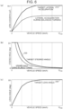
- FIG. 6 is a view for describing a method of determining the steered angle and the lean angle for setting the lateral acceleration acting on the center of gravity of the vehicle 1 to the target lateral acceleration.
- Vmax on the axis of abscissa in FIGS. 6 (a) to (c) represents the maximum speed of the vehicle 1.
- Data 210 of the continuous line shown in FIG. 6 (a) is data representing the target lateral acceleration.
- the target lateral acceleration according to the vehicle speed is set beforehand for the lateral acceleration 0 to Ac1.
- Data 220 of the continuous line shown in FIG. 6 (b) represents the target steered angle.
- the target steered angle according to the vehicle speed is set beforehand for the steered angle 0 to D1.
- the continuous line in FIG. 6 (c) represents the target lean angle.
- the target lean angle according to the vehicle speed is set beforehand for the lean angle 0 to D2.
- the broken line in FIG. 6 (a) represents the lateral acceleration during balanced turning.
- the target lateral acceleration represented by the data 220 of the continuous line is set such that a difference from the lateral acceleration during balanced turning in low vehicle speed regions becomes smaller than a difference from the lateral acceleration during balanced turning in high vehicle speed regions.
- the target lateral acceleration is set such that, when a difference between the target lateral acceleration corresponding to the lateral acceleration acting on the vehicle 1 in the imbalanced turning state and the lateral acceleration acting on the vehicle 1 during balanced turning is defined as a differential lateral acceleration, a rate of change in the differential lateral acceleration relative to the change in the vehicle speed in the highest speed region becomes lower than a rate of change in the differential lateral acceleration relative to the change in the vehicle speed in the lowest speed region.
- the broken line in FIG. 6 (b) represents the steered angle during balanced turning.
- the target steered angle represented by the data 220 of the continuous line has the same value as the steered angle during balanced turning in part of a speed region from the 0 (zero) vehicle speed to a predetermined speed, and is larger than the steered angle during balanced turning in the other speed regions, with the difference from the target steered angle becoming smaller as the vehicle speed becomes higher.
- the lean angle during balanced turning is not shown in FIG. 6 (c)
- the target lean angle shown in FIG. 6 (c) matches the lean angle during balanced turning.
- the vehicle 1 When the vehicle speed is high, the vehicle 1 turns with the steered angle of the front wheels 11 reduced and the lean angle increased compared with when the vehicle speed is low. In other words, when the vehicle speed is low, the vehicle 1 turns with the steered angle of the front wheels 11 increased and the lean angle reduced compared with when the vehicle speed is high. Therefore, as the vehicle speed becomes higher, the target steered angle becomes smaller and the target lean angle becomes larger.
- the data 210 on the target lateral acceleration shown in FIG. 6 (a) corresponds to the setting information indicated by the continuous line in FIG. 1 .
- the control device 100 controls the steering device 10 and the leaning device 20 such that the target lateral acceleration acts on the center of gravity of the vehicle 1 that is turning.
- the control device 100 may acquire the lateral acceleration of the vehicle 1 and control the steering device 10 and the leaning device 20 such that the lateral acceleration is set to the target lateral acceleration.
- the steered angle of the vehicle 1 is set to the target steered angle
- the lean angle is set to the target lean angle.
- the method of acquiring the lateral acceleration that is an acceleration of the vehicle 1 in the left or right direction is conventionally known and therefore details will be omitted.
- the lateral acceleration acting on the center of gravity of the vehicle 1 can be acquired using a capacitance sensor, a piezoresistive sensor, a piezoelectric sensor, an inertial measurement unit (IMU), etc.
- IMU inertial
- the setting information may include the data 220 shown in FIG. 6 (b) and data 230 shown in FIG. 6 (c) instead of or in addition to the data 210 shown in FIG. 6 (a) .
- the control device 100 can determine the target steered angle and the target lean angle by referring to the data 220, 230 based on the vehicle speed of the vehicle 1.
- the control device 100 controls the steering device 10 so as to set the steered angle of the front wheels 11 to the target steered angle and controls the leaning device 20 so as to set the lean angle of the vehicle 1 to the target lean angle
- the lateral acceleration acting on the center of gravity of the vehicle 1 can be set to the target lateral acceleration corresponding to the vehicle speed.
- FIG. 7 is a view for describing another method of determining the steered angle and the lean angle for setting the lateral acceleration acting on the center of gravity of the vehicle 1 to the target lateral acceleration.
- Data 221 on the target steered angle and data 231 on the target lean angle shown in FIG. 7 are data that are obtained from the data 210, 220, and 230 shown in FIG. 6 .
- the target lateral acceleration Ac1 and the target steered angle D1 shown in FIG. 7 (a) correspond to the lateral acceleration Ac1 shown in FIG. 6 (a) and the steered angle D1 shown in FIG. 6 (b) , respectively.
- the target lateral acceleration Ac1 and the target lean angle D2 shown in FIG. 7 (b) correspond to the lateral acceleration Ac1 shown in FIG. 6 (a) and the lean angle D2 shown in FIG. 6 (c) , respectively.
- the data 221 in FIG. 7 (a) shows correspondence between the target steered angle and the target lateral acceleration. As the target lateral acceleration becomes smaller, the target steered angle becomes larger. In other words, as the target lateral acceleration becomes larger, the target steered angle becomes smaller.
- the data 231 in FIG. 7 (b) shows correspondence between the target lean angle and the target lateral acceleration. As the target lateral acceleration becomes larger, the target lean angle becomes larger. In other words, as the target lateral acceleration becomes smaller, the target steered angle becomes smaller.
- the setting information that the control device 100 uses may include the data 210 shown in FIG. 6 (a) , the data 221 shown in FIG. 7 (a) , and the data 231 shown in FIG. 7 (b) .
- the control device 100 can determine, based on the target lateral acceleration, the target steered angle from the data 221 in FIG. 7 (a) and the target lean angle from the data 231 in FIG. 7 (b) .
- the control device 100 controls the steering device 10 and the leaning device 20 so as to set the steered angle and the lean angle of the vehicle 1 to the target steered angle and the target lean angle, respectively, the lateral acceleration acting on the center of gravity of the vehicle 1 can be set to the target lateral acceleration.
- FIG. 8 is a view showing a specific example of the vehicle 1.
- the vehicle 1 shown in FIG. 8 has, on an inside of the vehicle body that is covered by a cowl 2 forming an external appearance of the vehicle 1, the steering device 10 including the steering mechanism 111 and the steering mechanism drive unit 110, the leaning device 20 including the leaning mechanism 121 and the leaning mechanism drive unit 120, and the control device 100.
- the vehicle 1 includes many parts as components, including an accelerator and a brake. However, as such a vehicle 1 is conventionally known, detailed description thereof will be omitted.
- FIG. 9 is a view for describing specific examples of the steering device 10, the leaning device 20, and the control device 100.
- the steering mechanism 111 is driven by the steering actuator 110 that functions as the steering mechanism drive unit
- the leaning mechanism 121 is driven by the leaning actuator 120 that functions as the leaning mechanism drive unit.
- the control device 100 includes a vehicle information acquisition unit 101, a steered angle determination unit 102, a steering actuator control unit 103, a lean angle determination unit 104, and a leaning actuator control unit 105.
- a vehicle speed detection device 301 that detects the vehicle speed is provided, and the vehicle information acquisition unit 101 acquires the vehicle speed from the vehicle speed detection device 301.
- the vehicle speed detection device 301 is conventionally known and therefore description thereof will be omitted.
- the vehicle speed is detected based on a rotation speed of the wheels 11, 12 that is acquired using a rotation sensor, and an outside diameter of the wheels 11, 12.
- the leaning mechanism 121 shown in FIG. 9 is a parallelogram-link-type leaning mechanism.
- the leaning mechanism 121 includes an upper arm 501, a lower arm 502, a left member 503, a right member 504, a left suspension 505L, and a right suspension 505R.
- the upper arm 501 and the lower arm 502 are rotatably connected to a head pipe 40a at a front end of the frame 40.
- the left member 503 is rotatably connected to left end portions of the upper arm 501 and the lower arm 502.
- the left suspension 505L is connected through a bracket.
- the left front wheel 11L that is a steered wheel is rotatably connected to the left suspension 505L.
- the left suspension 505L allows the left front wheel 11L to move up and down relative to the left member 503.
- the right member 504 is rotatably connected to right end portions of the upper arm 501 and the lower arm 502.
- the right suspension 505R is connected through a bracket.
- the right front wheel 11R that is a steered wheel is rotatably connected to the right suspension 505R.
- the right suspension 505R allows the right front wheel 11R to move up and down relative to the right member 504.
- the leaning actuator 120 rotates the upper arm 501 and the lower arm 502 around the central axes Ca, Cb, respectively, in a clockwise direction in FIG. 9 , so that the left front wheel 11L and the right front wheel 11R lean in the left direction.
- the leaning actuator 120 rotates the upper arm 501 and the lower arm 502 around the central axes Ca, Cb, respectively, in a counterclockwise direction in FIG. 9 , so that the left front wheel 11L and the right front wheel 11R lean in the right direction.
- an electric motor fixed on the frame 40 is used as the leaning actuator 120.
- the leaning actuator control unit 105 controls a rotation direction and a rotation angle of an output shaft of the electric motor connected to the upper arm 501 or the lower arm 502, the lean angle of the vehicle 1 can be controlled to a lean angle determined by the lean angle determination unit 104.
- Control of the leaning actuator 120 is performed, for example, by controlling an output torque of the leaning actuator 120.
- the steering mechanism 111 includes a steering shaft 401 and a tie rod 402.
- the steering shaft 401 is inserted into the head pipe 40a and can rotate relative to the head pipe 40a.
- a central portion of the tie rod 402 is connected to a lower end portion of the steering shaft 401.
- the tie rod 402 moves in the left and right directions as the steering shaft 401 rotates.
- a left end portion of the tie rod 402 is connected to the left suspension 505L that supports the left front wheel 11L.
- a right end portion of the tie rod 402 is connected to the right suspension 505R that supports the right front wheel 11R.
- the steering shaft 401 is not mechanically connected to the handlebar 30.
- the steering actuator control unit 103 controls the steering actuator 110 so as to rotate the steering shaft 401.
- the steering actuator 110 rotates the steering shaft 401 such that the right front wheel 11R and the left front wheel 11L face the left direction.
- the steering actuator 110 rotates the steering shaft 401 such that the left front wheel 11L and the right front wheel 11R face the right direction.
- an electric motor fixed on the frame 40 is used as the steering actuator 110.
- the steering actuator control unit 103 controls a rotation direction and a rotation angle of an output shaft of the electric motor connected to the steering shaft 401, the steered angle of the front wheels 11 can be controlled to a steered angle determined by the steered angle determination unit 102.
- Control of the steering actuator 110 is performed, for example, by controlling an output torque of the steering actuator 110.
- the vehicle information acquisition unit 101 acquires the vehicle speed of the vehicle 1 from the vehicle speed detection device 301.
- the steered angle determination unit 102 determines the target lateral acceleration based on the vehicle speed acquired by the vehicle information acquisition unit 101, and determines the target steered angle corresponding to the target lateral acceleration.
- the steering actuator control unit 103 controls the steering actuator 110, which drives the steering mechanism 111, such that the steered angle of the front wheels 11 is set to the target steered angle determined by the steered angle determination unit 102.
- the lean angle determination unit 104 determines the target lateral acceleration based on the vehicle speed acquired by the vehicle information acquisition unit 101, and determines the target lean angle corresponding to the target lateral acceleration.
- the leaning actuator control unit 105 controls the leaning actuator 120, which drives the leaning mechanism 121, such that the lean angle of the vehicle 1 is set to the target lean angle determined by the lean angle determination unit 104. For example, when the steered angle of the vehicle 1 having leaned under the imbalanced turning control is controlled to a larger angle than the steered angle during balanced turning, a force that tries to raise the vehicle 1 toward an outer side of the turn, i.e., a force that tries to reduce the lean angle, acts on the vehicle 1.
- the leaning actuator control unit 105 controls the leaning actuator 120 such that the vehicle 1 in the leaned state does not rise toward the outer side of the turn, i.e., that the lean angle does not decrease.
- the lateral acceleration acting on the center of gravity of the vehicle 1 is set to the target lateral acceleration and the vehicle 1 turns.
- FIG. 10 is a view for describing the operation of the leaning actuator 120 that drives the leaning mechanism 121.
- the leaning actuator 120 is configured to change the lean angle of the vehicle 1 by applying a torque to the leaning mechanism 121.
- the lean angle of the vehicle 1 is changed by controlling the rotation direction and the output torque of the output shaft of the electric motor that functions as the leaning actuator 120.
- a value of the output torque of the output shaft is a value having a proportional relationship with a value of a current applied to the electric motor.
- the control device 100 controls the leaning actuator 120 such that the torque becomes larger as the lateral acceleration acting on the center of gravity of the vehicle 1 becomes larger. While FIG. 10 shows an example in which the relationship between the lateral acceleration and the torque changes linearly, this represents an example and it is not intended that the relationship between the lateral acceleration and the torque is limited thereto.
- a lateral acceleration determination unit may be provided between the vehicle information acquisition unit 101 shown in FIG. 9 on one side and the steered angle determination unit 102 and the lean angle determination unit 104 on the other side.
- the lateral acceleration determination unit may determine the target lateral acceleration according to the vehicle speed, and based on the target lateral acceleration, the steered angle determination unit 102 may determine the target steered angle and the lean angle determination unit 104 may determine the target lean angle.
- a timing when the leaning actuator control unit 105 starts to control the leaning actuator 120 to achieve the target lean angle may be before a timing when the steering actuator control unit 103 starts to control the steering actuator 110 to achieve the target steered angle.
- a control gain when the leaning actuator control unit 105 controls the leaning actuator 120 may be set to be larger than a control gain when the steering actuator control unit 103 controls the steering actuator 110.
- the control timings and the control gains are set such that, when an action of returning the lean angle to 0 degrees of straight forward movement and an action of returning the steered angle to 0 degrees of straight forward movement, after completion of turning of the vehicle 1, are compared, the action of returning the lean angle to 0 degrees ends first.
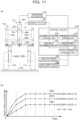
- FIG. 11 is a view for describing an example of the imbalanced turning control that is performed using the vehicle speed and the handlebar angle.
- the vehicle information acquisition unit 101 shown in FIG. 11 (a) acquires the vehicle speed from the vehicle speed detection device 301, and acquires the handlebar angle from a handlebar angle detection device 302.
- the handlebar angle detection device 302 is conventionally known and therefore description thereof will be omitted.
- the handlebar angle is detected using an angle sensor, an encoder, etc.
- FIG. 11 (b) is a view showing an example of setting information that is used when performing the imbalanced turning control based on the vehicle speed and the handlebar angle.
- a plurality of pieces of data 240 (240a to 240c) different in the target lateral acceleration according to the handlebar angle are prepared beforehand. While FIG. 11 (b) shows an example of the three pieces of data 240a to 240c, the data 240 on the target lateral acceleration is prepared for each handlebar angle.
- the handlebar angle becomes larger in order of H1, H2, H3 (H1 ⁇ H2 ⁇ H3) as shown in FIG. 11 (b) , the data 240a on the target lateral acceleration for the handlebar angle H3 is set to a larger value than the data 40b on the target lateral acceleration for the handlebar angle H2 in all the speed regions up to the maximum speed Vmax.
- the data 240b on the target lateral acceleration for the handlebar angle H2 is set to a larger value than the data 240c on the target lateral acceleration for the handlebar angle H1.
- the target lateral acceleration in each data 240 is set such that, when five regions into which the speed region of the vehicle 1 from the 0 (zero) vehicle speed to the maximum speed Vmax is equally divided are defined, a rate of change in the target lateral acceleration relative to the change in the vehicle speed in the highest speed region becomes lower than a rate of change in the target lateral acceleration relative to the change in the vehicle speed in the lowest speed region.
- the mean value of the rate of increase in the lateral acceleration in the highest speed region is smaller than the mean value of the rate of increase in the lateral acceleration in the lowest speed region.
- each data 240 is set such that a mean value of the target lateral acceleration in the lowest speed region becomes smaller than a mean value of the target lateral acceleration in the highest speed region.
- Each data 240 is set such that the lateral acceleration increases gradually in low vehicle speed regions including the lowest speed region and that the lateral acceleration assumes a constant value in high vehicle speed regions including the highest speed region.
- Each data 240 is set such that the target lateral acceleration becomes larger as the handlebar angle becomes larger.
- the vehicle information acquisition unit 101 acquires the vehicle speed of the vehicle 1 from the vehicle speed detection device 301 and acquires the handlebar angle from the handlebar angle detection device 302.
- the steered angle determination unit 102 selects, from the plurality of pieces of data 240, the data 240 corresponding to the handlebar angle acquired by the vehicle information acquisition unit 101. By referring to the selected data 240, the steered angle determination unit 102 determines the target lateral acceleration based on the vehicle speed acquired by the vehicle information acquisition unit 101, and determines the target steered angle corresponding to the target lateral acceleration.
- the steering actuator control unit 103 controls the steering actuator 110 such that the steered angle of the front wheels 11 is set to the target steered angle.
- the lean angle determination unit 104 selects, from the plurality of pieces of data 240, the data 240 corresponding to the handlebar angle acquired by the vehicle information acquisition unit 101. By referring to the selected data 240, the lean angle determination unit 104 determines the target lateral acceleration based on the vehicle speed acquired by the vehicle information acquisition unit 101, and determines the target lean angle corresponding to the target lateral acceleration.
- the leaning actuator control unit 105 controls the steering actuator 110 such that the lean angle of the vehicle 1 is set to the target lean angle.
- the lateral acceleration acting on the center of gravity of the vehicle 1 is set to the target lateral acceleration and the vehicle 1 turns.
- a lateral acceleration determination unit may be provided between the vehicle information acquisition unit 101 on one side and the steered angle determination unit 102 and the lean angle determination unit 104 on the other side.
- the lateral acceleration determination unit may select the data 240 according to the handlebar angle, and may determine the target lateral acceleration according to the vehicle speed in the data 240. Then, based on the target lateral acceleration, the steered angle determination unit 102 may determine the target steered angle and the lean angle determination unit 104 may determine the target lean angle.
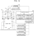
- FIG. 12 is a view for describing an example of the imbalanced turning control that is performed using the feedback control.
- the vehicle information acquisition unit 101 shown in FIG. 12 acquires the vehicle speed from the vehicle speed detection device 301, and acquires the handlebar angle from the handlebar angle detection device 302. Further, the vehicle information acquisition unit 101 acquires the lean angle of the vehicle 1 from a lean angle detection device 303, and acquires the steered angle of the front wheels 11 from a steered angle detection device 304.
- the steered angle detection device 304 is conventionally known and therefore description thereof will be omitted.
- the target steered angle is determined by the steered angle determination unit 102 and the target lean angle is determined by the lean angle determination unit 104.
- the steering actuator control unit 103 starts to control the steering actuator 110 that drives the steering mechanism 111.
- the steering actuator control unit 103 can acquire, through the vehicle information acquisition unit 101, the steered angle of the front wheels 11 detected by the steered angle detection device 304. While checking the steered angle of the front wheels 11, the steering actuator control unit 103 controls the steering actuator 110 such that the steered angle is set to the target steered angle.
- the lateral acceleration acting on the center of gravity of the vehicle 1 is set to the target lateral acceleration and the vehicle 1 turns.
- FIG. 13 is a view showing another specific example of the vehicle 1.
- the vehicle 1 has, on the frame 40 located frontward of the handlebar 30 as shown in FIG. 13 (a) , a double-wishbone-type leaning mechanism 121 as shown in FIG. 13 (b) .
- the structure and operation of the vehicle 1 shown in FIG. 13 are disclosed in, for example, International Publication No. WO 2017/082426 by the present applicant.
- the leaning mechanism 121 includes an upper left arm 601L, a lower left arm 602L, an upper right arm 601R, and a lower right arm 602R.
- Right end portions of the upper left arm 601L and the lower left arm 602L are rotatably connected to the frame 40, and left end portions thereof are rotatably connected to an upper end portion and a lower end portion of a left member 603L.
- Left end portions of the upper right arm 601R and the lower right arm 602R are rotatably connected to the frame 40, and right end portions thereof are rotatably connected to an upper end portion and a lower end portion of a right member 603R.
- the left front wheel 11L is rotatably connected to the left member 603L
- the right front wheel 11R is rotatably connected to the right member 603R.
- the left front wheel 11L and the right front wheel 11R can move up and down relative to the frame 40.
- a lower end portion of a left damper 605L is rotatably connected to a crossbar that forms the lower left arm 602L
- a lower end portion of a right damper 605R is rotatably connected to a crossbar that forms the lower right arm 602R.
- An upper end portion of the left damper 605L is rotatably connected to a left end portion of a coupling part 630
- an upper end portion of the right damper 605R is rotatably connected to a right end portion of the coupling part 630
- an upper end portion of a center arm 620 is rotatably connected to a central portion of the coupling part 630.
- a lower end portion of the center arm 620 is rotatably connected to the frame 40.
- the control device 100 can control the lean angle of the vehicle 1 by controlling a rotation direction and a rotation angle of the center arm 620 through the leaning actuator 120.
- the steering mechanism 111 of the vehicle 1 shown in FIG. 13 (b) includes the steering shaft 401, a left tie rod 402L, and a right tie rod 402R.
- the steering shaft 401 and the left member 603L that supports the left front wheel 11L are connected to each other by the left tie rod 402L.
- the steering shaft 401 and the right member 603R that supports the right front wheel 11R are connected to each other by the right tie rod 402R.
- the control device 100 controls the steering actuator 110 so as to move the left tie rod 402L and the right tie rod 402R through the steering shaft 401, so that the left front wheel 11L rotates around an axis C2a shown in FIG.
- the control device 100 can control the steered angle of the front wheels 11 by controlling movement directions and amounts of movement of the left tie rod 402L and the right tie rod 402R through the steering actuator 110.
- control device 100 can perform the imbalanced turning control of the vehicle 1 as described above by controlling the steering actuator 110 and the leaning actuator 120.
- the control until the vehicle 1 is put in a turning state has been mainly described. After ending the turn, the rider returns the handlebar angle to 0 degrees, and the control device 100 performs control that returns the steered angle of the front wheels 11 and the lean angle to 0 degrees, so that the vehicle 1 returns to the moving-straight-forward state.
- the example has been described in which the control device 100 starts the imbalanced turning control upon detecting a change in the handlebar angle resulting from the rider's turning operation.
- an aspect may be adopted in which the imbalanced turning control by the control device 100 is started upon detecting a change in the steered angle, the lean angle, etc., of the vehicle 1.
- the turning operation performed by the rider includes an operation for changing the steered angle of the front wheels 11 and an operation for changing the lean angle of the vehicle 1.
- the handlebar angle i.e., the steered angle
- the control device 100 may determine to start the imbalanced turning control based on at least one of the handlebar angle, the steered angle, and the lean angle having changed.
- the example has been described in which the vehicle 1 has the two front wheels 11 that are steered wheels and the one rear wheel 12 that is a driven wheel.
- an aspect may be adopted in which the vehicle 1 has one front wheel that is a steered wheel and two rear wheels that are driven wheels, or an aspect may be adopted in which the vehicle 1 has two front wheels that are steered wheels and two rear wheels that are driven wheels.
- an aspect in which only the rear wheel 12 is driven an aspect in which only the front wheels 11 are driven may be adopted, or an aspect in which both the front wheels 11 and the rear wheel 12 are driven may be adopted.
- the steered wheels can also be driven. In any case, it is possible to turn the vehicle 1 by controlling the steered angle of the front wheels 11 and the lean angle so as to set the lateral acceleration acting on the center of gravity of the vehicle 1 to the target lateral acceleration as described above.
- the configuration of the steering device 10 shown in this embodiment represents an example, and the configuration of the steering device 10 is not particularly limited as long as the steered angle of the steered wheels can be controlled as described above.
- the configuration of the leaning device 20 shown in this embodiment represents an example, and the configuration of the leaning device 20 is not particularly limited as long as the lean angle of the steered wheels can be controlled as described above. Since the entire vehicle 1 including the front wheels 11, the rear wheel 12, and the vehicle body lean to the same angle during turning, the control that changes the lean angle of the vehicle 1 in the above-described example is equivalent to control that changes the lean angle of the vehicle body of the vehicle 1.
- the processes of obtaining output values such as the target lateral acceleration, the target steered angle, and the target lean angle using the vehicle speed, the handlebar angle, etc., as input values has been described using graphs showing the relationships between the input values and the output values.
- these processes are performed using two-dimensional maps or arithmetic expressions showing the relationships between the input values and the output values.
- an aspect in which three-dimensional maps are used may be adopted.
- the target lateral acceleration and the target lean angle are determined from the vehicle speed using a three-dimensional map showing the relationships among the vehicle speed, the target steered angle, and the target lean angle for producing the target lateral acceleration.
- the order of execution of the control of the steered angle by the steering device 10 and the control of the lean angle by the leaning device 20 described in this embodiment is not particularly limited.
- the control of the steered angle and the control of the lean angle may be concurrently executed at the same time.
- the control for increasing the lean angle may be performed first before the control of the steered angle is performed.
- the control for increasing the steered angle may be performed first before and the control of the lean angle is performed.
- the control device 100 may gradually increase the steered angle of the front wheels 11 and the lean angle of the vehicle 1 to set them to the target steered angle and the target lean angle.
Landscapes
- Engineering & Computer Science (AREA)
- Mechanical Engineering (AREA)
- Steering Control In Accordance With Driving Conditions (AREA)
- Vehicle Body Suspensions (AREA)
Abstract
Description
- This disclosure relates to a leaning vehicle that turns by leaning the vehicle body.
- Conventionally, leaning vehicles that turn by leaning the vehicle body are known. For example,
Patent Literature 1 discloses a leaning vehicle including two front wheels and one rear wheel. In the leaning vehicle, the state of the vehicle that is turning can be controlled. When a rider operates a handlebar to start to turn from a moving-straight-forward state, the directions of the front wheels are set to a steered angle according to the handlebar operation. Further, when the rider operates the handlebar to start to turn, the vehicle body assumes a lean angle so as to lean toward the center of the turn. In the leaning vehicle described inPatent Literature 1, it is proposed to control the steered angle and the lean angle such that an additional centripetal force is generated for the front steered wheels and the rear wheel that are leaned during turning. - Patent Literature 1: International Publication No.
WO 2020/138395 - In a leaning vehicle in which a control device controls the steered angle and the lean angle, it is conceivable that the control device executes the control of the steered angle and the control of the lean angle such that a lateral acceleration that takes into account a vehicle speed of the leaning vehicle acts on the vehicle body.
- One of the objects of this disclosure is to provide a leaning vehicle in which a control device controls the steered angle and the lean angle, and in which the control device can execute the control of the steered angle and the control of the lean angle such that a lateral acceleration that takes into account a vehicle speed of the leaning vehicle acts on the vehicle body.
- A leaning vehicle according to this disclosure includes: wheels including two front steered wheels and at least one rear wheel; a leaning actuator that is configured to change a lean angle of a vehicle body when the leaning vehicle turns; a steering actuator that is configured to change a steered angle of the two front steered wheels when the leaning vehicle turns; and a control device that is configured to control at least the leaning actuator and the steering actuator. The leaning vehicle turns by leaning the vehicle body. When such a turning state in which a lean angle that the vehicle body forms with a perpendicular axis perpendicular to a ground surface is set to an angle that a resultant force, acting on the vehicle body, of a gravitational force and a centrifugal force directed toward an outer side of a turn forms with the perpendicular axis is defined as a balanced turning state, and such a turning state in which a lateral acceleration occurs that is larger than a lateral acceleration acting on the vehicle body in the balanced turning state is defined as an imbalanced turning state, the control device is configured to control the leaning actuator and the steering actuator such that, when five regions into which a speed region of the leaning vehicle up to a maximum speed is equally divided are defined, a rate of change in large lateral acceleration in the imbalanced turning state relative to a change in a vehicle speed in a highest speed region becomes lower than a rate of change in the large lateral acceleration in the imbalanced turning state relative to a change in the vehicle speed in a lowest speed region.
- In the above-described configuration, the control device may be configured to control the leaning actuator and the steering actuator so as to create the imbalanced turning state in which the lateral acceleration occurs that is larger than the lateral acceleration acting on the vehicle body in the balanced turning state, and control the leaning actuator and the steering actuator such that a mean value of the rate of change in the large lateral acceleration in the imbalanced turning state relative to the change in the vehicle speed in the highest speed region becomes smaller than a mean value of the rate of change in the large lateral acceleration in the imbalanced turning state relative to the change in the vehicle speed in the lowest speed region.
- In the above-described configuration, the control device may be configured to control the leaning actuator and the steering actuator so as to create the imbalanced turning state in which the lateral acceleration occurs that is larger than the lateral acceleration acting on the vehicle body in the balanced turning state, and control the leaning actuator and the steering actuator such that, when a differential lateral acceleration is defined that is a difference between the large lateral acceleration acting on the vehicle body in the imbalanced turning state and the lateral acceleration acting on the vehicle body in the balanced turning state, a rate of change in the differential lateral acceleration relative to the change in the vehicle speed in the highest speed region becomes lower than a rate of change in the differential lateral acceleration relative to the change in the vehicle speed in the lowest speed region.
- In the above-described configuration, the control device may be configured to control the leaning actuator and the steering actuator so as to create the imbalanced turning state in which the lateral acceleration occurs that is larger than the lateral acceleration acting on the vehicle body in the balanced turning state, and perform the control of the leaning actuator before the control of the steering actuator.
- In the above-described configuration, the control device may be configured to control the leaning actuator and the steering actuator so as to create the imbalanced turning state in which the lateral acceleration occurs that is larger than the lateral acceleration acting on the vehicle body in the balanced turning state, and sets a control gain of the leaning actuator to be larger than a control gain of the steering actuator.
- According to this disclosure, a leaning vehicle is provided in which a control device controls the steered angle and the lean angle, and in which the control device can execute the control of the steered angle and the control of the lean angle such that a lateral acceleration that takes into account the vehicle speed of the leaning vehicle acts on the vehicle body.
-
- [
FIG. 1] FIG. 1 is a view for describing an overview of a leaning vehicle according to an embodiment. - [
FIG. 2] FIG. 2 is a view for describing imbalanced turning control of the leaning vehicle. - [
FIG. 3] FIG. 3 is a view for describing control of a steered angle by a control device. - [
FIG. 4] FIG. 4 is a view for describing control of a lean angle by the control device. - [
FIG. 5] FIG. 5 is a view for describing an example of the imbalanced turning control of the leaning vehicle. - [
FIG. 6] FIG. 6 is a view for describing a method of determining the steered angle and the lean angle for setting a lateral acceleration acting on the center of gravity of the leaning vehicle to a target lateral acceleration. - [
FIG. 7] FIG. 7 is a view for describing another method of determining the steered angle and the lean angle for setting the lateral acceleration acting on the center of gravity of the leaning vehicle to the target lateral acceleration. - [
FIG. 8] FIG. 8 is a view showing a specific example of the leaning vehicle. - [
FIG. 9] FIG. 9 is a view for describing specific examples of a steering device, a leaning device, and the control device. - [
FIG. 10] FIG. 10 is a view for describing operation of the leaning device. - [
FIG. 11] FIG. 11 is a view for describing an example of the imbalanced turning control that is performed using a vehicle speed and a handlebar angle. - [
FIG. 12] FIG. 12 is a view for describing an example of the imbalanced turning control that is performed using feedback control. - [
FIG. 13] FIG. 13 is a view showing another specific example of the leaning vehicle. - A leaning vehicle according to this disclosure will be described below with reference to the accompanying drawings. The leaning vehicle has a plurality of wheels. While the numbers of front wheels and rear wheels included in the leaning vehicle are not particularly limited, in this embodiment, a leaning vehicle including two front wheels and one rear wheel will be described as an example. Hereinafter, the leaning vehicle will be referred to simply as a "vehicle."
-
FIG. 1 is a schematic view for describing avehicle 1 according to this embodiment. With a front face of thevehicle 1 as the front side,FIG. 1 schematically shows, on the upper left side, a top view of thevehicle 1 that is moving straight forward, and below it a front view of thesame vehicle 1. On the right side ofFIG. 1 , a top view and a front view of thevehicle 1 that is turning are schematically shown. When thevehicle 1 shown on the left side ofFIG. 1 that is moving straight forward turns, imbalanced turning control of thevehicle 1 is performed by acontrol device 100 shown at the center ofFIG. 1 , so that thevehicle 1 turns in a vehicle state shown on the right side ofFIG. 1 . In top views shown in this embodiment of thevehicle 1 that is turning, directions of steered wheels are indicated while depiction of a lean of thevehicle 1 is omitted, and in front views, the lean of thevehicle 1 is shown while depiction of the directions of the steered wheels is omitted. - As shown in
FIG. 1 , thevehicle 1 includes:wheels 11, 12 including two front steered wheels 11 (11L, 11R) and at least onerear wheel 12; asteering actuator 110 that is configured to change a steered angle A of the two front steered wheels 11 when thevehicle 1 turns; a leaningactuator 120 that is configured to change a lean angle B of thevehicle 1 when thevehicle 1 turns; and thecontrol device 100 that is configured to control at least the leaningactuator 120 and thesteering actuator 110. The steered angle A and the lean angle B of thevehicle 1 are changed as thesteering actuator 110 and theleaning actuator 120 are controlled by thecontrol device 100. Thevehicle 1 turns as the steered angle A and the lean angle B are changed from the steered angle A and the lean angle B of a moving-straightforward state. - The broken line shown in the graph of
FIG. 1 represents a relationship between a vehicle speed and a lateral acceleration in a balanced turning state. The balanced turning state refers to such a turning state in which, when thevehicle 1 turns, the lean angle B that thevehicle 1 forms with a perpendicular axis perpendicular to a ground surface is set to an angle that a resultant force, acting on the center of gravity of thevehicle 1, of a centrifugal force directed toward an outer side of the turn and the gravitational force forms with the perpendicular axis (seeFIG. 2 ). A conventional vehicle in which the imbalanced turning control is not performed turns in the balanced turning state. - As the
control device 100 executes the imbalanced turning control when thevehicle 1 turns, thevehicle 1 turns in an imbalanced turning state in which a lateral acceleration acts on thevehicle 1 that is larger than a lateral acceleration acting in the balanced turning state. For example, as indicated by the continuous line in the graph ofFIG. 1 , the lateral acceleration according to a vehicle speed is prepared beforehand as setting information, and thecontrol device 100 executes the imbalanced turning control based on the setting information such that the lateral acceleration of thevehicle 1 is set to a value according to the vehicle speed. - As shown in
FIG. 1 , thecontrol device 100 executes the imbalanced turning control such that, when five regions into which a speed region of thevehicle 1 from a 0 (zero) speed to a maximum speed Vmax is equally divided are defined, a rate of change in large lateral acceleration in the imbalanced turning state relative to a change in the vehicle speed in a highest speed region becomes lower than a rate of change in the large lateral acceleration in the imbalanced turning state relative to a change in the vehicle speed in a lowest speed region. -
FIG. 2 is a view for describing the imbalanced turning control of thevehicle 1. As shown inFIG. 2 (a) , the conventional vehicle that turns in the balanced turning state turns such that the angle between the resultant force of the gravitational force and the centrifugal force directed toward the outer side of the turn (inFIG. 2 (a) , "LATERAL ACCELERATION G1") and the perpendicular axis perpendicular to the ground surface (inFIG. 2 (a) , "0°") is set to a lean angle B1 of the vehicle. For example, the conventional vehicle traveling on a substantially horizontal ground surface turns such that the angle between the vector of the resultant force and the vector of the gravitational force is set to the same as the lean angle B1 of the vehicle. - By contrast, as shown in
FIG. 2 (b) , under the imbalanced turning control executed by thecontrol device 100, thevehicle 1 turns in the imbalanced turning state in which a lateral acceleration G2 occurs that is larger than the lateral acceleration G1 that occurs in the balanced turning state. In the imbalanced turning state, the angle between the resultant force of the gravitational force and the centrifugal force directed toward the outer side of the turn (inFIG. 2 (b) , "LATERAL ACCELERATION G2") and the perpendicular axis perpendicular to the ground surface is set to an angle different from the lean angle B1 of the vehicle. For example, thevehicle 1 traveling on a substantially horizontal ground surface turns such that the angle between the vector of the resultant force and the vector of the gravitational force is set to an angle larger than the lean angle B1 of the vehicle. - The lateral acceleration acting on the center of gravity of the
vehicle 1 and the lean angle of thevehicle 1 can be acquired using a measurement device, such as an inertial measurement unit (IMU). The lateral acceleration in the balanced turning state indicated by the broken line in the graph ofFIG. 1 can be calculated from the lean angle acquired by the measurement device. When the imbalanced turning control by thecontrol device 100 is executed, the lateral acceleration obtained by the measurement device indicates a larger value than the lateral acceleration calculated based on the lean angle. By comparing the lateral acceleration calculated from an actually measured value of the lean angle and an actually measured value of the lateral acceleration, it is possible to confirm that thevehicle 1 is turning in the imbalanced turning state, i.e., that the imbalanced turning control by thecontrol device 100 is being executed. - The continuous line of the imbalanced turning state shown in the graph of
FIG. 1 represents an example and is not intended to limit the relationship between the vehicle speed and the lateral acceleration in the imbalanced turning state. The relationship between the vehicle speed and the lateral acceleration is not particularly limited as long as the lateral acceleration in the imbalanced turning state is set to a larger value than the lateral acceleration in the balanced turning state at the same vehicle speed. For example, the relationship between the vehicle speed and the lateral acceleration in the imbalanced turning state may be as indicated by the long dashed and short dashed lines in the graph ofFIG. 1 . The relationship between the lateral acceleration and the vehicle speed in the imbalanced turning state can be set as appropriate according to, for example, the characteristics of thevehicle 1. - Next, an overview of the imbalanced turning control of the
vehicle 1 will be described. Hereinafter, thesteering actuator 110 may be referred to as a steeringmechanism drive unit 110, and the leaningactuator 120 may be referred to as a leaningmechanism drive unit 120. Thevehicle 1 includes the two front wheels 11 (11L, 11R) that are steered wheels, the onerear wheel 12 that is a driven wheel, aframe 40, aprime mover 50, aseat 60, and apower transmission unit 70. Thevehicle 1 is a saddle-riding-type vehicle that a rider rides by straddling theseat 60. As theprime mover 50 supported on theframe 40 drives therear wheel 12 through thepower transmission unit 70, thevehicle 1 moves forward while rotating the front wheels 11 and therear wheel 12 that are in contact with aground surface 700. The type of theprime mover 50 is not particularly limited, and may be an engine that is an internal combustion engine, or may be an electric motor, or may be a hybrid prime mover including an engine and an electric motor. The configuration of thepower transmission unit 70 is not limited either, and may be a configuration including a drive chain or may be a configuration including a driveshaft. - The
vehicle 1 includes ahandlebar 30, thecontrol device 100, asteering device 10 including a steering mechanism 111 (seeFIG. 9 ) and the steeringmechanism drive unit 110, and a leaningdevice 20 including a leaning mechanism 121 (seeFIG. 9 ) and the leaningmechanism drive unit 120. - When performing a turning operation, the rider operates the
handlebar 30 to change the steered angle of the front wheels 11 and the lean angle of thevehicle 1. Thehandlebar 30 functions as a turning operation input device. The rider can turn thevehicle 1 by performing a turning operation of turning thehandlebar 30 to the left or right and thereby changing the directions of the front wheels 11 that are steered wheels to the left or right in an advancing direction and leaning thevehicle 1 toward the center of the turn. The left and right directions mentioned in relation to thevehicle 1 in this embodiment are left and right directions as seen from the rider of thevehicle 1. -
FIG. 3 is a view for describing control of the steered angle by thecontrol device 100.FIGS. 3 (a) to (c) show top views of thevehicle 1 during straight forward movement, balanced turning, and the imbalanced turning control, respectively.FIG. 4 is a view for describing control of the lean angle by thecontrol device 100.FIGS. 4 (a) to (c) show front views of thevehicle 1 during straight forward movement, balanced turning, and the imbalanced turning control, respectively.FIGS. 4 (a) to (c) show front views of thevehicle 1 shown inFIGS. 3 (a) to (c) , respectively. "During balanced turning" shows the balanced turning state of the conventional vehicle, and "during imbalanced turning control" shows the imbalanced turning state of thevehicle 1. - The
steering mechanism 111 can change the directions of the two front wheels 11 to the same direction. Thesteering mechanism 111 changes the steered angle of the front wheels 11 according to driving by the steeringmechanism drive unit 110. The steeringmechanism drive unit 110 is configured to drive thesteering mechanism 111 so as to change the directions of the two front wheels 11 to the left direction as well as to the right direction. As shown inFIG. 3 , the steered angle A (A1, A2) indicates the directions of the front wheels 11 having been changed to the left or right in the advancing direction, with the directions of the front wheels 11 during straight forward movement as 0 degrees. - The leaning
mechanism 121 can change the lean angle of thevehicle 1 so as to lean thevehicle 1 to the left as well as to the right. The leaningmechanism 121 changes the lean angle of thevehicle 1 according to driving by the leaningmechanism drive unit 120. The leaningmechanism drive unit 120 is configured to drive the leaningmechanism 121 so as to increase as well as reduce the lean angle of thevehicle 1. When thevehicle 1 leans, a vehicle body, i.e., theentire vehicle 1 including the front wheels 11 and therear wheel 12, leans to the same lean angle. Therefore, as shown inFIG. 4 , the lean angle B (B 1, B2) can be indicated by the lean of the front wheels 11 toward the left side or the right side, with the angle of the front wheels 11 during straight forward movement as 0 degrees. For example, the lean of the front wheels 11 relative to theroad surface 700, with a direction perpendicular to theroad surface 700 as 0 degrees, is the lean angle B of thevehicle 1. - The
vehicle 1 is a steer-by-wire vehicle in which thehandlebar 30 and the front wheels 11 are cut off from each other. When the rider turns thehandlebar 30, thecontrol device 100 detects a handlebar angle as an amount of the rider's handlebar operation. As shown inFIG. 3 , a handlebar angle C (C1) represents an amount of operation that the rider has turned thehandlebar 30, with the direction of thehandlebar 30 during straight forward movement as 0 degrees. - The
control device 100 can acquire vehicle information showing a state of thevehicle 1. The vehicle information includes the handlebar angle and the vehicle speed. For example, when the rider turns thehandlebar 30 to the right and sets the handlebar angle C to 10 degrees while the vehicle is stationary (vehicle speed: zero), upon detecting this, thecontrol device 100 controls thesteering device 10 so as to set the steered angle A of the front wheels 11 to 10 degrees. Specifically, as thecontrol device 100 drives thesteering mechanism 111 by controlling the steeringmechanism drive unit 110, the front wheels 11 turn to the right and the steered angle A is set to 10 degrees. - When the rider turns the
handlebar 30 to start to turn thevehicle 1 while traveling straight forward, thecontrol device 100 executes the imbalanced turning control of thevehicle 1. Specifically, thecontrol device 100 first determines the lateral acceleration to be exerted on the center of gravity of thevehicle 1 based on the vehicle speed. The setting information in which the lateral acceleration is set according to the vehicle speed is prepared beforehand. Using the setting information, thecontrol device 100 determines the lateral acceleration to be exerted on the center of gravity of thevehicle 1. - As indicated by the continuous line in
FIG. 1 , the setting information includes data showing correspondence between the vehicle speed and the lateral acceleration. The lateral acceleration in the data is set so as to have a larger value than the lateral acceleration during balanced turning (in the balanced turning state). Thecontrol device 100 controls thesteering device 10 and the leaningdevice 20 so as to create a state (imbalanced turning state) in which the lateral acceleration acting on the center of gravity of thevehicle 1 that is turning is larger than the lateral acceleration during balanced turning. - For example, as shown in
FIG. 1 , the lateral acceleration is set such that, when five regions into which the speed region of thevehicle 1 from 0 (zero) to the maximum speed Vmax is equally divided are defined, the rate of change in the lateral acceleration in the imbalanced turning control relative to the change in the vehicle speed in the highest speed region becomes lower than the rate of change in the lateral acceleration in the imbalanced turning control relative to the change in the vehicle speed in the lowest speed region. A mean value of a rate of increase in the lateral acceleration in the highest speed region is smaller than a mean value of a rate of increase in the lateral acceleration in the lowest speed region. A mean value of the lateral acceleration in the lowest speed region is a smaller value than a mean value of the lateral acceleration in the highest speed region. In this embodiment, as indicated by the continuous line inFIG. 1 , the lateral acceleration in the imbalanced turning state is controlled so as to assume a constant value as the vehicle speed of thevehicle 1 approaches the maximum speed Vmax. The maximum speed Vmax of thevehicle 1 for defining the speed regions is set to the same as the actual maximum speed of thevehicle 1 or to a higher speed than the actual maximum speed. For example, the maximum speed may be a design value, or may be an actually measured value of the maximum speed of thevehicle 1, or may be a value that is set based on the design value or the actually measured value. - As shown in
FIG. 3 (a) andFIG. 4 (a) , during straight forward travel, the handlebar angle, the steered angle, and the lean angle are 0 degrees, and there is no lateral acceleration in thevehicle 1. When the rider operates thehandlebar 30 and sets the handlebar angle to C1 as shown inFIG. 3 (b) and FIG. 3 (c) , thevehicle 1 turns. During balanced turning, as shown inFIG. 3 (b) , the steered angle of the front wheels 11 is set to A1 as thecontrol device 100 controls thesteering device 10. The steered angle A1 in this case is equal to the handlebar angle C1 (A1 = C1). As shown inFIG. 4 (b) , in response to the rider's handlebar operation, thevehicle 1 leans toward the center of the turn and the lean angle is set toB 1. As described above, during balanced turning, the lean angle B1 of thevehicle 1 is set to the angle that the resultant force, acting on the center of gravity of thevehicle 1, of the centrifugal force (lateral acceleration G1) directed toward the outer side of the turn and the gravitational force forms with the perpendicular axis. The steered angle A1 during balanced turning need not be necessarily equal to the handlebar angle C1, and it is also possible to set the steered angle A1 to be larger or smaller than the handlebar angle. - In this embodiment, the
control device 100 controls thesteering device 10 and the leaningdevice 20 such that the lateral acceleration acting on thevehicle 1 is set to the lateral acceleration G2 that is larger than the lateral acceleration G1 during balanced turning. Specifically, thecontrol device 100 refers to the setting information based on the vehicle speed of thevehicle 1 and determines the lateral acceleration to be exerted on the center of gravity of thevehicle 1. As described above, the lateral acceleration included in the setting information is set so as to have a larger value than the lateral acceleration acting on thevehicle 1 during balanced turning. - The
control device 100 can perform steering increasing control that sets the steered angle of the front wheels 11 that are turning to a larger angle than the same angle as the handlebar angle. During the imbalanced turning control, thecontrol device 100 drives thesteering mechanism 111 by controlling the steeringmechanism drive unit 110, and thereby sets the steered angle of the front wheels 11 to the steered angle A2 that is larger than the steered angle A1 during balanced turning (A2 > A1) as shown inFIG. 3 (c) . Thus, as shown inFIG. 3 (c) , during the imbalanced turning control, thevehicle 1 turns in the steered-angle-added turning state in which the steered angle is increased compared with the steered angle during balanced turning. - During the imbalanced turning control under which the vehicle turns in the steered-angle-added turning state, as shown in
FIG. 2 (b) , the angle that the vector of the resultant force of the lateral acceleration and the gravitational force acting on the center of gravity of thevehicle 1 forms with the axis perpendicular to the ground surface is set to be larger than the lean angle of thevehicle 1. Therefore, a force that reduces the lean angle acts on thevehicle 1. Thecontrol device 100 drives the leaningmechanism 121 by controlling the leaningmechanism drive unit 120 so as to restrict this change. Specifically, thecontrol device 100 can control the leaningmechanism drive unit 120 such that the leaningmechanism 121 maintains the lean angle B1. That is, thecontrol device 100 performs the control such that the lean angle B2 during the imbalanced turning control shown inFIG. 4 (c) is set to the same angle as the lean angle B1 during the balanced turning. - Thus, the
control device 100 controls the steeringmechanism drive unit 110 such that the steered angle is set to be larger than the steered angle during the balanced turning, and sets the lateral acceleration acting on the center of gravity of thevehicle 1 to the lateral acceleration G2. Further, thecontrol device 100 can restrict a change in the lean angle of thevehicle 1 that occurs due to the steered angle being larger than the steered angle during balanced turning. -
FIG. 5 is a view showing an example of an actually measured value of the lateral acceleration obtained by performing the imbalanced turning control of the leaning vehicle. Thecontrol device 100 performs the imbalanced turning control in which a lateral acceleration acts on thevehicle 1 that is larger than the lateral acceleration acting on thevehicle 1 in the balanced turning state. Moreover, thecontrol device 100 controls thesteering device 10 and the leaningdevice 20 such that, when five regions into which the speed region of thevehicle 1 up to the maximum speed is equally divided are defined, the rate of change in the large lateral acceleration in the imbalanced turning state relative to the change in the vehicle speed in the highest speed region becomes lower than the rate of change in the large lateral acceleration in the imbalanced turning state relative to the change in the vehicle speed in the lowest speed region. -
Data 210a indicated by the broken line inFIG. 5 represents the lateral acceleration that thecontrol device 100 exerts on the center of gravity of thevehicle 1 by performing the imbalanced turning control.Data 210b indicated by the continuous line inFIG. 5 represents an example of an actually measured value of the lateral acceleration that acts on the center of gravity of thevehicle 1 during the imbalanced turning control by thecontrol device 100. The actually measured value of the lateral acceleration varies depending on various factors such as the weight of the rider, the conditions of the road surface, the wind direction, the wind speed, the equipment of thevehicle 1, and the setting conditions of thevehicle 1. Therefore, as shown inFIG. 5 , thedata 210a on the lateral acceleration that is set beforehand and thedata 210b that is the actually measured lateral acceleration do not always match. The imbalanced turning control by thecontrol device 100 as termed in this embodiment is not limited to control under which the value of the lateral acceleration actually measured in thevehicle 1 matches the lateral acceleration in thedata 210a that is set beforehand. The imbalanced turning control by thecontrol device 100 includes control under which, as indicated by thedata 210b, the actually measured value of the lateral acceleration of thevehicle 1 indicates a different value from thedata 210a that is set in the setting information. - In the following, to simplify the description, the lateral acceleration that the
control device 100 exerts on the center of gravity of thevehicle 1 by performing the imbalanced turning control will be referred to as a target lateral acceleration, and the steered angle and the lean angle of thevehicle 1 for producing the target lateral acceleration will be referred to as a target steered angle and a target lean angle, respectively, in continuing the description.FIG. 6 is a view for describing a method of determining the steered angle and the lean angle for setting the lateral acceleration acting on the center of gravity of thevehicle 1 to the target lateral acceleration. Vmax on the axis of abscissa inFIGS. 6 (a) to (c) represents the maximum speed of thevehicle 1. -
Data 210 of the continuous line shown inFIG. 6 (a) is data representing the target lateral acceleration. The target lateral acceleration according to the vehicle speed is set beforehand for thelateral acceleration 0 to Ac1.Data 220 of the continuous line shown inFIG. 6 (b) represents the target steered angle. The target steered angle according to the vehicle speed is set beforehand for the steeredangle 0 to D1. The continuous line inFIG. 6 (c) represents the target lean angle. The target lean angle according to the vehicle speed is set beforehand for thelean angle 0 to D2. - The broken line in
FIG. 6 (a) represents the lateral acceleration during balanced turning. The target lateral acceleration represented by thedata 220 of the continuous line is set such that a difference from the lateral acceleration during balanced turning in low vehicle speed regions becomes smaller than a difference from the lateral acceleration during balanced turning in high vehicle speed regions. Further, the target lateral acceleration is set such that, when a difference between the target lateral acceleration corresponding to the lateral acceleration acting on thevehicle 1 in the imbalanced turning state and the lateral acceleration acting on thevehicle 1 during balanced turning is defined as a differential lateral acceleration, a rate of change in the differential lateral acceleration relative to the change in the vehicle speed in the highest speed region becomes lower than a rate of change in the differential lateral acceleration relative to the change in the vehicle speed in the lowest speed region. The broken line inFIG. 6 (b) represents the steered angle during balanced turning. The target steered angle represented by thedata 220 of the continuous line has the same value as the steered angle during balanced turning in part of a speed region from the 0 (zero) vehicle speed to a predetermined speed, and is larger than the steered angle during balanced turning in the other speed regions, with the difference from the target steered angle becoming smaller as the vehicle speed becomes higher. While the lean angle during balanced turning is not shown inFIG. 6 (c) , when thecontrol device 100 performs the imbalanced turning control that maintains the lean angle during balanced turning, the target lean angle shown inFIG. 6 (c) matches the lean angle during balanced turning. - When the vehicle speed is high, the
vehicle 1 turns with the steered angle of the front wheels 11 reduced and the lean angle increased compared with when the vehicle speed is low. In other words, when the vehicle speed is low, thevehicle 1 turns with the steered angle of the front wheels 11 increased and the lean angle reduced compared with when the vehicle speed is high. Therefore, as the vehicle speed becomes higher, the target steered angle becomes smaller and the target lean angle becomes larger. - The
data 210 on the target lateral acceleration shown inFIG. 6 (a) corresponds to the setting information indicated by the continuous line inFIG. 1 . Thecontrol device 100 controls thesteering device 10 and the leaningdevice 20 such that the target lateral acceleration acts on the center of gravity of thevehicle 1 that is turning. For example, thecontrol device 100 may acquire the lateral acceleration of thevehicle 1 and control thesteering device 10 and the leaningdevice 20 such that the lateral acceleration is set to the target lateral acceleration. As a result, the steered angle of thevehicle 1 is set to the target steered angle, and the lean angle is set to the target lean angle. The method of acquiring the lateral acceleration that is an acceleration of thevehicle 1 in the left or right direction is conventionally known and therefore details will be omitted. For example, the lateral acceleration acting on the center of gravity of thevehicle 1 can be acquired using a capacitance sensor, a piezoresistive sensor, a piezoelectric sensor, an inertial measurement unit (IMU), etc. - The setting information may include the
data 220 shown inFIG. 6 (b) anddata 230 shown inFIG. 6 (c) instead of or in addition to thedata 210 shown inFIG. 6 (a) . In this case, thecontrol device 100 can determine the target steered angle and the target lean angle by referring to thedata vehicle 1. As thecontrol device 100 controls thesteering device 10 so as to set the steered angle of the front wheels 11 to the target steered angle and controls the leaningdevice 20 so as to set the lean angle of thevehicle 1 to the target lean angle, the lateral acceleration acting on the center of gravity of thevehicle 1 can be set to the target lateral acceleration corresponding to the vehicle speed. -
FIG. 7 is a view for describing another method of determining the steered angle and the lean angle for setting the lateral acceleration acting on the center of gravity of thevehicle 1 to the target lateral acceleration.Data 221 on the target steered angle anddata 231 on the target lean angle shown inFIG. 7 are data that are obtained from thedata FIG. 6 . The target lateral acceleration Ac1 and the target steered angle D1 shown inFIG. 7 (a) correspond to the lateral acceleration Ac1 shown inFIG. 6 (a) and the steered angle D1 shown inFIG. 6 (b) , respectively. The target lateral acceleration Ac1 and the target lean angle D2 shown inFIG. 7 (b) correspond to the lateral acceleration Ac1 shown inFIG. 6 (a) and the lean angle D2 shown inFIG. 6 (c) , respectively. - The
data 221 inFIG. 7 (a) shows correspondence between the target steered angle and the target lateral acceleration. As the target lateral acceleration becomes smaller, the target steered angle becomes larger. In other words, as the target lateral acceleration becomes larger, the target steered angle becomes smaller. Thedata 231 inFIG. 7 (b) shows correspondence between the target lean angle and the target lateral acceleration. As the target lateral acceleration becomes larger, the target lean angle becomes larger. In other words, as the target lateral acceleration becomes smaller, the target steered angle becomes smaller. - The setting information that the
control device 100 uses may include thedata 210 shown inFIG. 6 (a) , thedata 221 shown inFIG. 7 (a) , and thedata 231 shown inFIG. 7 (b) . In this case, upon determining the target lateral acceleration by referring to thedata 210 inFIG. 6 (a) based on the vehicle speed of thevehicle 1, thecontrol device 100 can determine, based on the target lateral acceleration, the target steered angle from thedata 221 inFIG. 7 (a) and the target lean angle from thedata 231 inFIG. 7 (b) . As thecontrol device 100 controls thesteering device 10 and the leaningdevice 20 so as to set the steered angle and the lean angle of thevehicle 1 to the target steered angle and the target lean angle, respectively, the lateral acceleration acting on the center of gravity of thevehicle 1 can be set to the target lateral acceleration. - Next, the imbalanced turning control performed in the
vehicle 1 will be described using a specific example.FIG. 8 is a view showing a specific example of thevehicle 1. Thevehicle 1 shown inFIG. 8 has, on an inside of the vehicle body that is covered by acowl 2 forming an external appearance of thevehicle 1, thesteering device 10 including thesteering mechanism 111 and the steeringmechanism drive unit 110, the leaningdevice 20 including the leaningmechanism 121 and the leaningmechanism drive unit 120, and thecontrol device 100. Other than the components shown inFIG. 1 , thevehicle 1 includes many parts as components, including an accelerator and a brake. However, as such avehicle 1 is conventionally known, detailed description thereof will be omitted. -
FIG. 9 is a view for describing specific examples of thesteering device 10, the leaningdevice 20, and thecontrol device 100. In the example shown inFIG. 9 , thesteering mechanism 111 is driven by thesteering actuator 110 that functions as the steering mechanism drive unit, and the leaningmechanism 121 is driven by the leaningactuator 120 that functions as the leaning mechanism drive unit. - The
control device 100 includes a vehicleinformation acquisition unit 101, a steeredangle determination unit 102, a steeringactuator control unit 103, a leanangle determination unit 104, and a leaningactuator control unit 105. In thevehicle 1, a vehiclespeed detection device 301 that detects the vehicle speed is provided, and the vehicleinformation acquisition unit 101 acquires the vehicle speed from the vehiclespeed detection device 301. The vehiclespeed detection device 301 is conventionally known and therefore description thereof will be omitted. For example, the vehicle speed is detected based on a rotation speed of thewheels 11, 12 that is acquired using a rotation sensor, and an outside diameter of thewheels 11, 12. - The leaning
mechanism 121 shown inFIG. 9 is a parallelogram-link-type leaning mechanism. The leaningmechanism 121 includes anupper arm 501, alower arm 502, aleft member 503, aright member 504, aleft suspension 505L, and aright suspension 505R. - The
upper arm 501 and thelower arm 502 are rotatably connected to ahead pipe 40a at a front end of theframe 40. Theleft member 503 is rotatably connected to left end portions of theupper arm 501 and thelower arm 502. At a lower end portion of theleft member 503, theleft suspension 505L is connected through a bracket. The leftfront wheel 11L that is a steered wheel is rotatably connected to theleft suspension 505L. Theleft suspension 505L allows the leftfront wheel 11L to move up and down relative to theleft member 503. Theright member 504 is rotatably connected to right end portions of theupper arm 501 and thelower arm 502. At a lower end portion of theright member 504, theright suspension 505R is connected through a bracket. The rightfront wheel 11R that is a steered wheel is rotatably connected to theright suspension 505R. Theright suspension 505R allows the rightfront wheel 11R to move up and down relative to theright member 504. - When the
upper arm 501 and thelower arm 502 rotate around central axes Ca, Cb, respectively, on thehead pipe 40a, relative positions of the leftfront wheel 11L and the rightfront wheel 11R in a vehicle body up-down direction relative to theframe 40 change, so that the leftfront wheel 11L and the rightfront wheel 11R lean at the same time to the same angle. - Specifically, when turning the
vehicle 1 in the left direction, the leaningactuator 120 rotates theupper arm 501 and thelower arm 502 around the central axes Ca, Cb, respectively, in a clockwise direction inFIG. 9 , so that the leftfront wheel 11L and the rightfront wheel 11R lean in the left direction. When turning thevehicle 1 in the right direction, the leaningactuator 120 rotates theupper arm 501 and thelower arm 502 around the central axes Ca, Cb, respectively, in a counterclockwise direction inFIG. 9 , so that the leftfront wheel 11L and the rightfront wheel 11R lean in the right direction. - For example, an electric motor fixed on the
frame 40 is used as the leaningactuator 120. As the leaningactuator control unit 105 controls a rotation direction and a rotation angle of an output shaft of the electric motor connected to theupper arm 501 or thelower arm 502, the lean angle of thevehicle 1 can be controlled to a lean angle determined by the leanangle determination unit 104. Control of the leaningactuator 120 is performed, for example, by controlling an output torque of the leaningactuator 120. - The
steering mechanism 111 includes asteering shaft 401 and atie rod 402. The steeringshaft 401 is inserted into thehead pipe 40a and can rotate relative to thehead pipe 40a. A central portion of thetie rod 402 is connected to a lower end portion of thesteering shaft 401. Thetie rod 402 moves in the left and right directions as thesteering shaft 401 rotates. - A left end portion of the
tie rod 402 is connected to theleft suspension 505L that supports the leftfront wheel 11L. A right end portion of thetie rod 402 is connected to theright suspension 505R that supports the rightfront wheel 11R. When thetie rod 402 moves in the left or right direction, the leftfront wheel 11L and the rightfront wheel 11R change their directions to the left or right. - The steering
shaft 401 is not mechanically connected to thehandlebar 30. When the rider turns thehandlebar 30, the steeringactuator control unit 103 controls thesteering actuator 110 so as to rotate thesteering shaft 401. When turning thevehicle 1 in the left direction, thesteering actuator 110 rotates thesteering shaft 401 such that the rightfront wheel 11R and the leftfront wheel 11L face the left direction. When turning thevehicle 1 in the right direction, thesteering actuator 110 rotates thesteering shaft 401 such that the leftfront wheel 11L and the rightfront wheel 11R face the right direction. - For example, an electric motor fixed on the
frame 40 is used as thesteering actuator 110. As the steeringactuator control unit 103 controls a rotation direction and a rotation angle of an output shaft of the electric motor connected to thesteering shaft 401, the steered angle of the front wheels 11 can be controlled to a steered angle determined by the steeredangle determination unit 102. Control of thesteering actuator 110 is performed, for example, by controlling an output torque of thesteering actuator 110. - When the rider turns the
handlebar 30 to start a turning operation, the imbalanced turning control of thevehicle 1 is started. The vehicleinformation acquisition unit 101 acquires the vehicle speed of thevehicle 1 from the vehiclespeed detection device 301. The steeredangle determination unit 102 determines the target lateral acceleration based on the vehicle speed acquired by the vehicleinformation acquisition unit 101, and determines the target steered angle corresponding to the target lateral acceleration. The steeringactuator control unit 103 controls thesteering actuator 110, which drives thesteering mechanism 111, such that the steered angle of the front wheels 11 is set to the target steered angle determined by the steeredangle determination unit 102. - The lean
angle determination unit 104 determines the target lateral acceleration based on the vehicle speed acquired by the vehicleinformation acquisition unit 101, and determines the target lean angle corresponding to the target lateral acceleration. The leaningactuator control unit 105 controls the leaningactuator 120, which drives the leaningmechanism 121, such that the lean angle of thevehicle 1 is set to the target lean angle determined by the leanangle determination unit 104. For example, when the steered angle of thevehicle 1 having leaned under the imbalanced turning control is controlled to a larger angle than the steered angle during balanced turning, a force that tries to raise thevehicle 1 toward an outer side of the turn, i.e., a force that tries to reduce the lean angle, acts on thevehicle 1. The leaningactuator control unit 105 controls the leaningactuator 120 such that thevehicle 1 in the leaned state does not rise toward the outer side of the turn, i.e., that the lean angle does not decrease. - As a result, as described above, in a state where the steered angle of the front wheels 11 is set to the target steered angle larger than the steered angle during balanced turning and the lean angle of the
vehicle 1 is maintained at the target lean angle, the lateral acceleration acting on the center of gravity of thevehicle 1 is set to the target lateral acceleration and thevehicle 1 turns. -
FIG. 10 is a view for describing the operation of the leaningactuator 120 that drives the leaningmechanism 121. The leaningactuator 120 is configured to change the lean angle of thevehicle 1 by applying a torque to the leaningmechanism 121. For example, the lean angle of thevehicle 1 is changed by controlling the rotation direction and the output torque of the output shaft of the electric motor that functions as the leaningactuator 120. A value of the output torque of the output shaft is a value having a proportional relationship with a value of a current applied to the electric motor. - When the vehicle speed of the
vehicle 1 is high, the lateral acceleration acting on the center of gravity of thevehicle 1 having started to turn is large compared with when the vehicle speed is low. Further, when the vehicle speed of thevehicle 1 is high, a force that results from increasing the steered angle during turning and that tries to raise thevehicle 1, i.e., that tries to reduce the lean angle, also becomes large compared with when the vehicle speed is low, so that the torque of the leaningactuator 120 for restricting this force needs to be increased. Therefore, as shown inFIG. 10 , thecontrol device 100 controls the leaningactuator 120 such that the torque becomes larger as the lateral acceleration acting on the center of gravity of thevehicle 1 becomes larger. WhileFIG. 10 shows an example in which the relationship between the lateral acceleration and the torque changes linearly, this represents an example and it is not intended that the relationship between the lateral acceleration and the torque is limited thereto. - A lateral acceleration determination unit may be provided between the vehicle
information acquisition unit 101 shown inFIG. 9 on one side and the steeredangle determination unit 102 and the leanangle determination unit 104 on the other side. In this case, the lateral acceleration determination unit may determine the target lateral acceleration according to the vehicle speed, and based on the target lateral acceleration, the steeredangle determination unit 102 may determine the target steered angle and the leanangle determination unit 104 may determine the target lean angle. - A timing when the leaning
actuator control unit 105 starts to control the leaningactuator 120 to achieve the target lean angle may be before a timing when the steeringactuator control unit 103 starts to control thesteering actuator 110 to achieve the target steered angle. A control gain when the leaningactuator control unit 105 controls the leaningactuator 120 may be set to be larger than a control gain when the steeringactuator control unit 103 controls thesteering actuator 110. In other words, an aspect may be adopted in which the control timings and the control gains are set such that, when an action of returning the lean angle to 0 degrees of straight forward movement and an action of returning the steered angle to 0 degrees of straight forward movement, after completion of turning of thevehicle 1, are compared, the action of returning the lean angle to 0 degrees ends first. - An aspect may be adopted in which the
control device 100 controls the steered angle and the lean angle of the front wheels 11 based on the vehicle speed and the handlebar angle.FIG. 11 is a view for describing an example of the imbalanced turning control that is performed using the vehicle speed and the handlebar angle. The vehicleinformation acquisition unit 101 shown inFIG. 11 (a) acquires the vehicle speed from the vehiclespeed detection device 301, and acquires the handlebar angle from a handlebarangle detection device 302. The handlebarangle detection device 302 is conventionally known and therefore description thereof will be omitted. For example, the handlebar angle is detected using an angle sensor, an encoder, etc. -
FIG. 11 (b) is a view showing an example of setting information that is used when performing the imbalanced turning control based on the vehicle speed and the handlebar angle. A plurality of pieces of data 240 (240a to 240c) different in the target lateral acceleration according to the handlebar angle are prepared beforehand. WhileFIG. 11 (b) shows an example of the three pieces ofdata 240a to 240c, the data 240 on the target lateral acceleration is prepared for each handlebar angle. - The larger the handlebar angle is, the larger the value is to which the target lateral acceleration is set. When the handlebar angle becomes larger in order of H1, H2, H3 (H1 < H2 < H3), as shown in
FIG. 11 (b) , thedata 240a on the target lateral acceleration for the handlebar angle H3 is set to a larger value than the data 40b on the target lateral acceleration for the handlebar angle H2 in all the speed regions up to the maximum speed Vmax. Similarly, thedata 240b on the target lateral acceleration for the handlebar angle H2 is set to a larger value than thedata 240c on the target lateral acceleration for the handlebar angle H1. - For example, as shown in
FIG. 11 (b) , the target lateral acceleration in each data 240 is set such that, when five regions into which the speed region of thevehicle 1 from the 0 (zero) vehicle speed to the maximum speed Vmax is equally divided are defined, a rate of change in the target lateral acceleration relative to the change in the vehicle speed in the highest speed region becomes lower than a rate of change in the target lateral acceleration relative to the change in the vehicle speed in the lowest speed region. The mean value of the rate of increase in the lateral acceleration in the highest speed region is smaller than the mean value of the rate of increase in the lateral acceleration in the lowest speed region. Further, each data 240 is set such that a mean value of the target lateral acceleration in the lowest speed region becomes smaller than a mean value of the target lateral acceleration in the highest speed region. Each data 240 is set such that the lateral acceleration increases gradually in low vehicle speed regions including the lowest speed region and that the lateral acceleration assumes a constant value in high vehicle speed regions including the highest speed region. Each data 240 is set such that the target lateral acceleration becomes larger as the handlebar angle becomes larger. - When the rider turns the
handlebar 30 to start a turning operation, the imbalanced turning control of thevehicle 1 is started. The vehicleinformation acquisition unit 101 acquires the vehicle speed of thevehicle 1 from the vehiclespeed detection device 301 and acquires the handlebar angle from the handlebarangle detection device 302. The steeredangle determination unit 102 selects, from the plurality of pieces of data 240, the data 240 corresponding to the handlebar angle acquired by the vehicleinformation acquisition unit 101. By referring to the selected data 240, the steeredangle determination unit 102 determines the target lateral acceleration based on the vehicle speed acquired by the vehicleinformation acquisition unit 101, and determines the target steered angle corresponding to the target lateral acceleration. The steeringactuator control unit 103 controls thesteering actuator 110 such that the steered angle of the front wheels 11 is set to the target steered angle. - Similarly, the lean
angle determination unit 104 selects, from the plurality of pieces of data 240, the data 240 corresponding to the handlebar angle acquired by the vehicleinformation acquisition unit 101. By referring to the selected data 240, the leanangle determination unit 104 determines the target lateral acceleration based on the vehicle speed acquired by the vehicleinformation acquisition unit 101, and determines the target lean angle corresponding to the target lateral acceleration. The leaningactuator control unit 105 controls thesteering actuator 110 such that the lean angle of thevehicle 1 is set to the target lean angle. - As a result, as described above, in the state where the steered angle of the front wheels 11 is set to the target steered angle larger than the steered angle during balanced turning, and the lean angle of the
vehicle 1 is maintained at the target lean angle, the lateral acceleration acting on the center of gravity of thevehicle 1 is set to the target lateral acceleration and thevehicle 1 turns. - A lateral acceleration determination unit may be provided between the vehicle
information acquisition unit 101 on one side and the steeredangle determination unit 102 and the leanangle determination unit 104 on the other side. In this case, the lateral acceleration determination unit may select the data 240 according to the handlebar angle, and may determine the target lateral acceleration according to the vehicle speed in the data 240. Then, based on the target lateral acceleration, the steeredangle determination unit 102 may determine the target steered angle and the leanangle determination unit 104 may determine the target lean angle. - An aspect may be adopted in which the
control device 100 performs feedback control that controls the steered angle and the lean angle of thevehicle 1 while detecting the steered angle and the lean angle.FIG. 12 is a view for describing an example of the imbalanced turning control that is performed using the feedback control. The vehicleinformation acquisition unit 101 shown inFIG. 12 acquires the vehicle speed from the vehiclespeed detection device 301, and acquires the handlebar angle from the handlebarangle detection device 302. Further, the vehicleinformation acquisition unit 101 acquires the lean angle of thevehicle 1 from a leanangle detection device 303, and acquires the steered angle of the front wheels 11 from a steeredangle detection device 304. The steeredangle detection device 304 is conventionally known and therefore description thereof will be omitted. For example, the steered angle is detected using an angle sensor, an encoder, etc. The leanangle detection device 303 is conventionally known and therefore description thereof will be omitted. For example, the lean angle of thevehicle 1 is detected using an angle sensor, a gyroscope sensor, an encoder, an IMU, etc. - Based on the vehicle information acquired by the vehicle
information acquisition unit 101, as described inFIG. 9 andFIG. 11 , the target steered angle is determined by the steeredangle determination unit 102 and the target lean angle is determined by the leanangle determination unit 104. - When the target steered angle is determined, the steering
actuator control unit 103 starts to control thesteering actuator 110 that drives thesteering mechanism 111. The steeringactuator control unit 103 can acquire, through the vehicleinformation acquisition unit 101, the steered angle of the front wheels 11 detected by the steeredangle detection device 304. While checking the steered angle of the front wheels 11, the steeringactuator control unit 103 controls thesteering actuator 110 such that the steered angle is set to the target steered angle. - When the target lean angle is determined, the leaning
actuator control unit 105 starts to control the leaningactuator 120 that derives the leaningmechanism 121. The leaningactuator control unit 105 can acquire, through the vehicleinformation acquisition unit 101, the lean angle of thevehicle 1 detected by the leanangle detection device 303. While checking the lean angle of thevehicle 1, the leaningactuator control unit 105 controls the leaningactuator 120 such that the lean angle is set to the target lean angle. - As a result, as described above, in the state where the steered angle of the front wheels 11 is set to the target steered angle larger than the steered angle during balanced turning, and the lean angle of the
vehicle 1 is maintained at the target lean angle, the lateral acceleration acting on the center of gravity of thevehicle 1 is set to the target lateral acceleration and thevehicle 1 turns. - Next, another example of the
vehicle 1 will be described.FIG. 13 is a view showing another specific example of thevehicle 1. Thevehicle 1 has, on theframe 40 located frontward of thehandlebar 30 as shown inFIG. 13 (a) , a double-wishbone-type leaning mechanism 121 as shown inFIG. 13 (b) . The structure and operation of thevehicle 1 shown inFIG. 13 are disclosed in, for example, International Publication No.WO 2017/082426 by the present applicant. - As shown in
FIG. 13 (b) , the leaningmechanism 121 includes an upper left arm 601L, a lowerleft arm 602L, an upperright arm 601R, and a lowerright arm 602R. Right end portions of the upper left arm 601L and the lowerleft arm 602L are rotatably connected to theframe 40, and left end portions thereof are rotatably connected to an upper end portion and a lower end portion of aleft member 603L. Left end portions of the upperright arm 601R and the lowerright arm 602R are rotatably connected to theframe 40, and right end portions thereof are rotatably connected to an upper end portion and a lower end portion of aright member 603R. The leftfront wheel 11L is rotatably connected to theleft member 603L, and the rightfront wheel 11R is rotatably connected to theright member 603R. Thus, the leftfront wheel 11L and the rightfront wheel 11R can move up and down relative to theframe 40. - A lower end portion of a
left damper 605L is rotatably connected to a crossbar that forms the lowerleft arm 602L, and a lower end portion of aright damper 605R is rotatably connected to a crossbar that forms the lowerright arm 602R. An upper end portion of theleft damper 605L is rotatably connected to a left end portion of acoupling part 630, and an upper end portion of theright damper 605R is rotatably connected to a right end portion of thecoupling part 630, and an upper end portion of acenter arm 620 is rotatably connected to a central portion of thecoupling part 630. A lower end portion of thecenter arm 620 is rotatably connected to theframe 40. As thecoupling part 630 swings to the left and right around a portion connected to thecenter arm 620 as the center, upward motion of the leftfront wheel 11L is transmitted as downward motion of the rightfront wheel 11R, and upward motion of the rightfront wheel 11R is transmitted as downward motion of the leftfront wheel 11L. As the leftfront wheel 11L moves upward and the rightfront wheel 11R moves downward, the front wheels 11 and thevehicle 1 lean to the left, and as the rightfront wheel 11R moves upward and the leftfront wheel 11L moves downward, the front wheels 11 and thevehicle 1 lean to the right. - As the leaning
actuator 120 fixed on theframe 40 drives thecenter arm 620, thecenter arm 620 swings around its lower end portion as the center. When thecenter arm 620 swings, the relative positions of the leftfront wheel 11L and the rightfront wheel 11R in the vehicle body up-down direction relative to theframe 40 change through thecoupling part 630. Thecontrol device 100 can control the lean angle of thevehicle 1 by controlling a rotation direction and a rotation angle of thecenter arm 620 through the leaningactuator 120. - The
steering mechanism 111 of thevehicle 1 shown inFIG. 13 (b) includes thesteering shaft 401, aleft tie rod 402L, and aright tie rod 402R. The steeringshaft 401 and theleft member 603L that supports the leftfront wheel 11L are connected to each other by theleft tie rod 402L. The steeringshaft 401 and theright member 603R that supports the rightfront wheel 11R are connected to each other by theright tie rod 402R. When the rider turns thehandlebar 30, thecontrol device 100 controls thesteering actuator 110 so as to move theleft tie rod 402L and theright tie rod 402R through thesteering shaft 401, so that the leftfront wheel 11L rotates around an axis C2a shown inFIG. 13 (b) and the rightfront wheel 11R rotates around an axis C2b. Thecontrol device 100 can control the steered angle of the front wheels 11 by controlling movement directions and amounts of movement of theleft tie rod 402L and theright tie rod 402R through thesteering actuator 110. - Also in the
vehicle 1 shown inFIG. 13 , thecontrol device 100 can perform the imbalanced turning control of thevehicle 1 as described above by controlling thesteering actuator 110 and the leaningactuator 120. - In this embodiment, the control until the
vehicle 1 is put in a turning state has been mainly described. After ending the turn, the rider returns the handlebar angle to 0 degrees, and thecontrol device 100 performs control that returns the steered angle of the front wheels 11 and the lean angle to 0 degrees, so that thevehicle 1 returns to the moving-straight-forward state. - In this embodiment, the example has been described in which the
control device 100 starts the imbalanced turning control upon detecting a change in the handlebar angle resulting from the rider's turning operation. However, an aspect may be adopted in which the imbalanced turning control by thecontrol device 100 is started upon detecting a change in the steered angle, the lean angle, etc., of thevehicle 1. The turning operation performed by the rider includes an operation for changing the steered angle of the front wheels 11 and an operation for changing the lean angle of thevehicle 1. When thevehicle 1 turns, the handlebar angle, i.e., the steered angle, of the front wheels 11 and the lean angle of thevehicle 1 change. Thecontrol device 100 may determine to start the imbalanced turning control based on at least one of the handlebar angle, the steered angle, and the lean angle having changed. - In this embodiment, the example has been described in which the
vehicle 1 has the two front wheels 11 that are steered wheels and the onerear wheel 12 that is a driven wheel. However, an aspect may be adopted in which thevehicle 1 has one front wheel that is a steered wheel and two rear wheels that are driven wheels, or an aspect may be adopted in which thevehicle 1 has two front wheels that are steered wheels and two rear wheels that are driven wheels. Other than the aspect in which only therear wheel 12 is driven, an aspect in which only the front wheels 11 are driven may be adopted, or an aspect in which both the front wheels 11 and therear wheel 12 are driven may be adopted. For example, when an in-wheel motor is used, the steered wheels can also be driven. In any case, it is possible to turn thevehicle 1 by controlling the steered angle of the front wheels 11 and the lean angle so as to set the lateral acceleration acting on the center of gravity of thevehicle 1 to the target lateral acceleration as described above. - The configuration of the
steering device 10 shown in this embodiment represents an example, and the configuration of thesteering device 10 is not particularly limited as long as the steered angle of the steered wheels can be controlled as described above. Similarly, the configuration of the leaningdevice 20 shown in this embodiment represents an example, and the configuration of the leaningdevice 20 is not particularly limited as long as the lean angle of the steered wheels can be controlled as described above. Since theentire vehicle 1 including the front wheels 11, therear wheel 12, and the vehicle body lean to the same angle during turning, the control that changes the lean angle of thevehicle 1 in the above-described example is equivalent to control that changes the lean angle of the vehicle body of thevehicle 1. - In this embodiment, the processes of obtaining output values such as the target lateral acceleration, the target steered angle, and the target lean angle using the vehicle speed, the handlebar angle, etc., as input values has been described using graphs showing the relationships between the input values and the output values. However, an aspect may be adopted in which these processes are performed using two-dimensional maps or arithmetic expressions showing the relationships between the input values and the output values. Or an aspect in which three-dimensional maps are used may be adopted. For example, an aspect may be adopted in which the target lateral acceleration and the target lean angle are determined from the vehicle speed using a three-dimensional map showing the relationships among the vehicle speed, the target steered angle, and the target lean angle for producing the target lateral acceleration.
- The order of execution of the control of the steered angle by the
steering device 10 and the control of the lean angle by the leaningdevice 20 described in this embodiment is not particularly limited. The control of the steered angle and the control of the lean angle may be concurrently executed at the same time. The control for increasing the lean angle may be performed first before the control of the steered angle is performed. The control for increasing the steered angle may be performed first before and the control of the lean angle is performed. For example, thecontrol device 100 may gradually increase the steered angle of the front wheels 11 and the lean angle of thevehicle 1 to set them to the target steered angle and the target lean angle. -
- 1
- Vehicle
- 2
- Cowl
- 10
- Steering device
- 11 (11L, 11R)
- Front wheel
- 12
- Rear wheel
- 20
- Leaning device
- 30
- Handlebar
- 40
- Frame
- 50
- Prime mover
- 60
- Seat
- 70
- Power transmission unit
- 100
- Control device
- 110
- Steering mechanism drive unit (steering actuator)
- 111
- Steering mechanism
- 120
- Leaning mechanism drive unit (leaning actuator)
- 121
- Leaning mechanism
Claims (5)
- A leaning vehicle comprising:wheels including two front steered wheels and at least one rear wheel;a leaning actuator that is configured to change a lean angle of a vehicle body when the leaning vehicle turns;a steering actuator that is configured to change a steered angle of the two front steered wheels when the leaning vehicle turns; anda control device that is configured to control at least the leaning actuator and the steering actuator,the leaning vehicle turning by leaning the vehicle body,wherein, when such a turning state in which a lean angle that the vehicle body forms with a perpendicular axis perpendicular to a ground surface is set to an angle that a resultant force, acting on the vehicle body, of a gravitational force and a centrifugal force directed toward an outer side of a turn forms with the perpendicular axis is defined as a balanced turning state, and such a turning state in which a lateral acceleration occurs that is larger than a lateral acceleration acting on the vehicle body in the balanced turning state is defined as an imbalanced turning state,the control device is configured to control the leaning actuator and the steering actuator such that, when five regions into which a speed region of the leaning vehicle up to a maximum speed is equally divided are defined, a rate of change in large lateral acceleration in the imbalanced turning state relative to a change in a vehicle speed in a highest speed region becomes lower than a rate of change in the large lateral acceleration in the imbalanced turning state relative to a change in the vehicle speed in a lowest speed region.
- The leaning vehicle according to claim 1, wherein the control device is configured to control the leaning actuator and the steering actuator so as to create the imbalanced turning state in which the lateral acceleration occurs that is larger than the lateral acceleration acting on the vehicle body in the balanced turning state, and control the leaning actuator and the steering actuator such that a mean value of the rate of change in the large lateral acceleration in the imbalanced turning state relative to the change in the vehicle speed in the highest speed region becomes smaller than a mean value of the rate of change in the large lateral acceleration in the imbalanced turning state relative to the change in the vehicle speed in the lowest speed region.
- The leaning vehicle according to claim 1 or 2, wherein the control device is configured to control the leaning actuator and the steering actuator so as to create the imbalanced turning state in which the lateral acceleration occurs that is larger than the lateral acceleration acting on the vehicle body in the balanced turning state, and control the leaning actuator and the steering actuator such that, when a differential lateral acceleration is defined that is a difference between the large lateral acceleration acting on the vehicle body in the imbalanced turning state and the lateral acceleration acting on the vehicle body in the balanced turning state, a rate of change in the differential lateral acceleration relative to the change in the vehicle speed in the highest speed region becomes lower than a rate of change in the differential lateral acceleration relative to the change in the vehicle speed in the lowest speed region.
- The leaning vehicle according to any one of claims 1 to 3, wherein the control device is configured to control the leaning actuator and the steering actuator so as to create the imbalanced turning state in which the lateral acceleration occurs that is larger than the lateral acceleration acting on the vehicle body in the balanced turning state, and perform the control of the leaning actuator before the control of the steering actuator.
- The leaning vehicle according to any one of claims 1 to 4, wherein the control device is configured to control the leaning actuator and the steering actuator so as to create the imbalanced turning state in which the lateral acceleration occurs that is larger than the lateral acceleration acting on the vehicle body in the balanced turning state, and set a control gain of the leaning actuator to be larger than a control gain of the steering actuator.
Applications Claiming Priority (2)
| Application Number | Priority Date | Filing Date | Title |
|---|---|---|---|
| PCT/JP2021/047350 WO2023119422A1 (en) | 2021-12-21 | 2021-12-21 | Tilting vehicle |
| PCT/JP2022/047098 WO2023120572A1 (en) | 2021-12-21 | 2022-12-21 | Tilting vehicle |
Publications (2)
| Publication Number | Publication Date |
|---|---|
| EP4434863A1 true EP4434863A1 (en) | 2024-09-25 |
| EP4434863A4 EP4434863A4 (en) | 2025-02-26 |
Family
ID=86901625
Family Applications (1)
| Application Number | Title | Priority Date | Filing Date |
|---|---|---|---|
| EP22911274.3A Withdrawn EP4434863A4 (en) | 2021-12-21 | 2022-12-21 | TILT VEHICLE |
Country Status (3)
| Country | Link |
|---|---|
| US (1) | US20240336325A1 (en) |
| EP (1) | EP4434863A4 (en) |
| WO (2) | WO2023119422A1 (en) |
Families Citing this family (1)
| Publication number | Priority date | Publication date | Assignee | Title |
|---|---|---|---|---|
| JP2025069712A (en) * | 2023-10-18 | 2025-05-01 | ヤマハ発動機株式会社 | Saddle-type vehicle |
Family Cites Families (7)
| Publication number | Priority date | Publication date | Assignee | Title |
|---|---|---|---|---|
| JP5273020B2 (en) * | 2009-04-10 | 2013-08-28 | 株式会社エクォス・リサーチ | vehicle |
| JPWO2014054697A1 (en) * | 2012-10-02 | 2016-08-25 | 学校法人日本大学 | Motor motion control method, motor motion control apparatus and motor vehicle |
| JP6515197B2 (en) | 2015-11-13 | 2019-05-15 | ヤマハ発動機株式会社 | Lean vehicle |
| JP6666995B2 (en) * | 2016-03-23 | 2020-03-18 | ヤマハ発動機株式会社 | Lean attitude control device for lean vehicle with left and right inclined wheels and lean vehicle with left and right inclined wheels |
| JP2018127140A (en) * | 2017-02-09 | 2018-08-16 | トヨタ自動車株式会社 | Auto tilt vehicle |
| EP3889021B1 (en) | 2018-12-27 | 2025-10-15 | Yamaha Hatsudoki Kabushiki Kaisha | Leaning vehicle with a steerable front wheel |
| JP2021160609A (en) * | 2020-03-31 | 2021-10-11 | 株式会社エクォス・リサーチ | Mobile device |
-
2021
- 2021-12-21 WO PCT/JP2021/047350 patent/WO2023119422A1/en not_active Ceased
-
2022
- 2022-12-21 EP EP22911274.3A patent/EP4434863A4/en not_active Withdrawn
- 2022-12-21 WO PCT/JP2022/047098 patent/WO2023120572A1/en not_active Ceased
-
2024
- 2024-06-19 US US18/748,061 patent/US20240336325A1/en active Pending
Also Published As
| Publication number | Publication date |
|---|---|
| WO2023119422A1 (en) | 2023-06-29 |
| EP4434863A4 (en) | 2025-02-26 |
| US20240336325A1 (en) | 2024-10-10 |
| WO2023120572A1 (en) | 2023-06-29 |
Similar Documents
| Publication | Publication Date | Title |
|---|---|---|
| US20180264905A1 (en) | Automatic tilting vehicle | |
| CN101549709B (en) | Vehicle behavior control apparatus and control method | |
| US20130226405A1 (en) | Vehicle control device | |
| EP3666634B1 (en) | Leaning vehicle | |
| JP7366281B2 (en) | motorcycle | |
| CN106553711A (en) | For controlling vehicle, the system and method for active air dynamic elements | |
| JP6728393B2 (en) | Angular velocity acquisition device around the vertical axis of the lean vehicle road surface | |
| JP6898428B2 (en) | vehicle | |
| JP6603953B2 (en) | vehicle | |
| JP2013144471A (en) | Vehicle | |
| JP2024038470A (en) | Tilting vehicle with steered front wheels | |
| CN110386216B (en) | Automatic tilting vehicle | |
| US20240336325A1 (en) | Leaning vehicle | |
| JP2025522405A (en) | How to Enhance Vehicle Dynamics with Flywheel and Steering | |
| JP2010162958A (en) | Vehicle control device | |
| EP4434864A1 (en) | Tilting vehicle | |
| WO2023145321A1 (en) | Tilting vehicle | |
| WO2023120582A1 (en) | Tilting vehicle | |
| TWI860065B (en) | Tilt the vehicle | |
| JP4161829B2 (en) | Vehicle attitude control device | |
| JP7643203B2 (en) | Vehicle steering system, gain determination map creation method | |
| WO2023120580A1 (en) | Tilting vehicle | |
| JP2021195072A (en) | Vehicle steering device | |
| JP7742388B2 (en) | Steering control system for motorcycles | |
| WO2023120575A1 (en) | Tilting vehicle |
Legal Events
| Date | Code | Title | Description |
|---|---|---|---|
| STAA | Information on the status of an ep patent application or granted ep patent |
Free format text: STATUS: THE INTERNATIONAL PUBLICATION HAS BEEN MADE |
|
| PUAI | Public reference made under article 153(3) epc to a published international application that has entered the european phase |
Free format text: ORIGINAL CODE: 0009012 |
|
| STAA | Information on the status of an ep patent application or granted ep patent |
Free format text: STATUS: REQUEST FOR EXAMINATION WAS MADE |
|
| 17P | Request for examination filed |
Effective date: 20240619 |
|
| AK | Designated contracting states |
Kind code of ref document: A1 Designated state(s): AL AT BE BG CH CY CZ DE DK EE ES FI FR GB GR HR HU IE IS IT LI LT LU LV MC ME MK MT NL NO PL PT RO RS SE SI SK SM TR |
|
| A4 | Supplementary search report drawn up and despatched |
Effective date: 20250127 |
|
| RIC1 | Information provided on ipc code assigned before grant |
Ipc: B62K 5/08 20060101ALI20250121BHEP Ipc: B62K 5/027 20130101ALI20250121BHEP Ipc: B62K 5/10 20130101AFI20250121BHEP |
|
| DAV | Request for validation of the european patent (deleted) | ||
| DAX | Request for extension of the european patent (deleted) | ||
| GRAJ | Information related to disapproval of communication of intention to grant by the applicant or resumption of examination proceedings by the epo deleted |
Free format text: ORIGINAL CODE: EPIDOSDIGR1 |
|
| GRAP | Despatch of communication of intention to grant a patent |
Free format text: ORIGINAL CODE: EPIDOSNIGR1 |
|
| STAA | Information on the status of an ep patent application or granted ep patent |
Free format text: STATUS: THE APPLICATION HAS BEEN WITHDRAWN |
|
| 18W | Application withdrawn |
Effective date: 20251209 |