EP4434856A1 - Actuator, charge port cover, and vehicle - Google Patents
Actuator, charge port cover, and vehicle Download PDFInfo
- Publication number
- EP4434856A1 EP4434856A1 EP23778148.9A EP23778148A EP4434856A1 EP 4434856 A1 EP4434856 A1 EP 4434856A1 EP 23778148 A EP23778148 A EP 23778148A EP 4434856 A1 EP4434856 A1 EP 4434856A1
- Authority
- EP
- European Patent Office
- Prior art keywords
- transmission
- output shaft
- motor
- clutch mechanism
- port cover
- Prior art date
- Legal status (The legal status is an assumption and is not a legal conclusion. Google has not performed a legal analysis and makes no representation as to the accuracy of the status listed.)
- Pending
Links
Images


Classifications
-
- F—MECHANICAL ENGINEERING; LIGHTING; HEATING; WEAPONS; BLASTING
- F16—ENGINEERING ELEMENTS AND UNITS; GENERAL MEASURES FOR PRODUCING AND MAINTAINING EFFECTIVE FUNCTIONING OF MACHINES OR INSTALLATIONS; THERMAL INSULATION IN GENERAL
- F16D—COUPLINGS FOR TRANSMITTING ROTATION; CLUTCHES; BRAKES
- F16D43/00—Automatic clutches
- F16D43/02—Automatic clutches actuated entirely mechanically
- F16D43/20—Automatic clutches actuated entirely mechanically controlled by torque, e.g. overload-release clutches, slip-clutches with means by which torque varies the clutching pressure
- F16D43/202—Automatic clutches actuated entirely mechanically controlled by torque, e.g. overload-release clutches, slip-clutches with means by which torque varies the clutching pressure of the ratchet type
-
- B—PERFORMING OPERATIONS; TRANSPORTING
- B60—VEHICLES IN GENERAL
- B60K—ARRANGEMENT OR MOUNTING OF PROPULSION UNITS OR OF TRANSMISSIONS IN VEHICLES; ARRANGEMENT OR MOUNTING OF PLURAL DIVERSE PRIME-MOVERS IN VEHICLES; AUXILIARY DRIVES FOR VEHICLES; INSTRUMENTATION OR DASHBOARDS FOR VEHICLES; ARRANGEMENTS IN CONNECTION WITH COOLING, AIR INTAKE, GAS EXHAUST OR FUEL SUPPLY OF PROPULSION UNITS IN VEHICLES
- B60K15/00—Arrangement in connection with fuel supply of combustion engines or other fuel consuming energy converters, e.g. fuel cells; Mounting or construction of fuel tanks
- B60K15/03—Fuel tanks
- B60K15/04—Tank inlets
- B60K15/05—Inlet covers
-
- B—PERFORMING OPERATIONS; TRANSPORTING
- B60—VEHICLES IN GENERAL
- B60L—PROPULSION OF ELECTRICALLY-PROPELLED VEHICLES; SUPPLYING ELECTRIC POWER FOR AUXILIARY EQUIPMENT OF ELECTRICALLY-PROPELLED VEHICLES; ELECTRODYNAMIC BRAKE SYSTEMS FOR VEHICLES IN GENERAL; MAGNETIC SUSPENSION OR LEVITATION FOR VEHICLES; MONITORING OPERATING VARIABLES OF ELECTRICALLY-PROPELLED VEHICLES; ELECTRIC SAFETY DEVICES FOR ELECTRICALLY-PROPELLED VEHICLES
- B60L53/00—Methods of charging batteries, specially adapted for electric vehicles; Charging stations or on-board charging equipment therefor; Exchange of energy storage elements in electric vehicles
- B60L53/10—Methods of charging batteries, specially adapted for electric vehicles; Charging stations or on-board charging equipment therefor; Exchange of energy storage elements in electric vehicles characterised by the energy transfer between the charging station and the vehicle
- B60L53/14—Conductive energy transfer
- B60L53/16—Connectors, e.g. plugs or sockets, specially adapted for charging electric vehicles
-
- B—PERFORMING OPERATIONS; TRANSPORTING
- B62—LAND VEHICLES FOR TRAVELLING OTHERWISE THAN ON RAILS
- B62D—MOTOR VEHICLES; TRAILERS
- B62D25/00—Superstructure or monocoque structure sub-units; Parts or details thereof not otherwise provided for
- B62D25/24—Superstructure sub-units with access or drainage openings having movable or removable closures; Sealing means therefor
-
- E—FIXED CONSTRUCTIONS
- E05—LOCKS; KEYS; WINDOW OR DOOR FITTINGS; SAFES
- E05B—LOCKS; ACCESSORIES THEREFOR; HANDCUFFS
- E05B81/00—Power-actuated vehicle locks
- E05B81/24—Power-actuated vehicle locks characterised by constructional features of the actuator or the power transmission
- E05B81/32—Details of the actuator transmission
- E05B81/46—Clutches
-
- E—FIXED CONSTRUCTIONS
- E05—LOCKS; KEYS; WINDOW OR DOOR FITTINGS; SAFES
- E05B—LOCKS; ACCESSORIES THEREFOR; HANDCUFFS
- E05B83/00—Vehicle locks specially adapted for particular types of wing or vehicle
- E05B83/28—Locks for glove compartments, console boxes, fuel inlet covers or the like
- E05B83/34—Locks for glove compartments, console boxes, fuel inlet covers or the like for fuel inlet covers essentially flush with the vehicle surface
-
- E—FIXED CONSTRUCTIONS
- E05—LOCKS; KEYS; WINDOW OR DOOR FITTINGS; SAFES
- E05F—DEVICES FOR MOVING WINGS INTO OPEN OR CLOSED POSITION; CHECKS FOR WINGS; WING FITTINGS NOT OTHERWISE PROVIDED FOR, CONCERNED WITH THE FUNCTIONING OF THE WING
- E05F15/00—Power-operated mechanisms for wings
- E05F15/60—Power-operated mechanisms for wings using electrical actuators
- E05F15/603—Power-operated mechanisms for wings using electrical actuators using rotary electromotors
- E05F15/611—Power-operated mechanisms for wings using electrical actuators using rotary electromotors for swinging wings
- E05F15/614—Power-operated mechanisms for wings using electrical actuators using rotary electromotors for swinging wings operated by meshing gear wheels, one of which being mounted at the wing pivot axis; operated by a motor acting directly on the wing pivot axis
-
- B—PERFORMING OPERATIONS; TRANSPORTING
- B60—VEHICLES IN GENERAL
- B60K—ARRANGEMENT OR MOUNTING OF PROPULSION UNITS OR OF TRANSMISSIONS IN VEHICLES; ARRANGEMENT OR MOUNTING OF PLURAL DIVERSE PRIME-MOVERS IN VEHICLES; AUXILIARY DRIVES FOR VEHICLES; INSTRUMENTATION OR DASHBOARDS FOR VEHICLES; ARRANGEMENTS IN CONNECTION WITH COOLING, AIR INTAKE, GAS EXHAUST OR FUEL SUPPLY OF PROPULSION UNITS IN VEHICLES
- B60K15/00—Arrangement in connection with fuel supply of combustion engines or other fuel consuming energy converters, e.g. fuel cells; Mounting or construction of fuel tanks
- B60K15/03—Fuel tanks
- B60K15/04—Tank inlets
- B60K15/05—Inlet covers
- B60K2015/0515—Arrangements for closing or opening of inlet cover
-
- B—PERFORMING OPERATIONS; TRANSPORTING
- B60—VEHICLES IN GENERAL
- B60K—ARRANGEMENT OR MOUNTING OF PROPULSION UNITS OR OF TRANSMISSIONS IN VEHICLES; ARRANGEMENT OR MOUNTING OF PLURAL DIVERSE PRIME-MOVERS IN VEHICLES; AUXILIARY DRIVES FOR VEHICLES; INSTRUMENTATION OR DASHBOARDS FOR VEHICLES; ARRANGEMENTS IN CONNECTION WITH COOLING, AIR INTAKE, GAS EXHAUST OR FUEL SUPPLY OF PROPULSION UNITS IN VEHICLES
- B60K15/00—Arrangement in connection with fuel supply of combustion engines or other fuel consuming energy converters, e.g. fuel cells; Mounting or construction of fuel tanks
- B60K15/03—Fuel tanks
- B60K15/04—Tank inlets
- B60K15/05—Inlet covers
- B60K2015/0515—Arrangements for closing or opening of inlet cover
- B60K2015/053—Arrangements for closing or opening of inlet cover with hinged connection to the vehicle body
-
- B—PERFORMING OPERATIONS; TRANSPORTING
- B60—VEHICLES IN GENERAL
- B60K—ARRANGEMENT OR MOUNTING OF PROPULSION UNITS OR OF TRANSMISSIONS IN VEHICLES; ARRANGEMENT OR MOUNTING OF PLURAL DIVERSE PRIME-MOVERS IN VEHICLES; AUXILIARY DRIVES FOR VEHICLES; INSTRUMENTATION OR DASHBOARDS FOR VEHICLES; ARRANGEMENTS IN CONNECTION WITH COOLING, AIR INTAKE, GAS EXHAUST OR FUEL SUPPLY OF PROPULSION UNITS IN VEHICLES
- B60K15/00—Arrangement in connection with fuel supply of combustion engines or other fuel consuming energy converters, e.g. fuel cells; Mounting or construction of fuel tanks
- B60K15/03—Fuel tanks
- B60K15/04—Tank inlets
- B60K15/05—Inlet covers
- B60K2015/0515—Arrangements for closing or opening of inlet cover
- B60K2015/0538—Arrangements for closing or opening of inlet cover with open or close mechanism automatically actuated
-
- E—FIXED CONSTRUCTIONS
- E05—LOCKS; KEYS; WINDOW OR DOOR FITTINGS; SAFES
- E05Y—INDEXING SCHEME ASSOCIATED WITH SUBCLASSES E05D AND E05F, RELATING TO CONSTRUCTION ELEMENTS, ELECTRIC CONTROL, POWER SUPPLY, POWER SIGNAL OR TRANSMISSION, USER INTERFACES, MOUNTING OR COUPLING, DETAILS, ACCESSORIES, AUXILIARY OPERATIONS NOT OTHERWISE PROVIDED FOR, APPLICATION THEREOF
- E05Y2201/00—Constructional elements; Accessories therefor
- E05Y2201/20—Brakes; Disengaging means; Holders; Stops; Valves; Accessories therefor
- E05Y2201/214—Disengaging means
- E05Y2201/216—Clutches
-
- E—FIXED CONSTRUCTIONS
- E05—LOCKS; KEYS; WINDOW OR DOOR FITTINGS; SAFES
- E05Y—INDEXING SCHEME ASSOCIATED WITH SUBCLASSES E05D AND E05F, RELATING TO CONSTRUCTION ELEMENTS, ELECTRIC CONTROL, POWER SUPPLY, POWER SIGNAL OR TRANSMISSION, USER INTERFACES, MOUNTING OR COUPLING, DETAILS, ACCESSORIES, AUXILIARY OPERATIONS NOT OTHERWISE PROVIDED FOR, APPLICATION THEREOF
- E05Y2201/00—Constructional elements; Accessories therefor
- E05Y2201/20—Brakes; Disengaging means; Holders; Stops; Valves; Accessories therefor
- E05Y2201/23—Actuation thereof
- E05Y2201/244—Actuation thereof by manual operation
-
- E—FIXED CONSTRUCTIONS
- E05—LOCKS; KEYS; WINDOW OR DOOR FITTINGS; SAFES
- E05Y—INDEXING SCHEME ASSOCIATED WITH SUBCLASSES E05D AND E05F, RELATING TO CONSTRUCTION ELEMENTS, ELECTRIC CONTROL, POWER SUPPLY, POWER SIGNAL OR TRANSMISSION, USER INTERFACES, MOUNTING OR COUPLING, DETAILS, ACCESSORIES, AUXILIARY OPERATIONS NOT OTHERWISE PROVIDED FOR, APPLICATION THEREOF
- E05Y2201/00—Constructional elements; Accessories therefor
- E05Y2201/40—Motors; Magnets; Springs; Weights; Accessories therefor
- E05Y2201/43—Motors
- E05Y2201/434—Electromotors; Details thereof
-
- E—FIXED CONSTRUCTIONS
- E05—LOCKS; KEYS; WINDOW OR DOOR FITTINGS; SAFES
- E05Y—INDEXING SCHEME ASSOCIATED WITH SUBCLASSES E05D AND E05F, RELATING TO CONSTRUCTION ELEMENTS, ELECTRIC CONTROL, POWER SUPPLY, POWER SIGNAL OR TRANSMISSION, USER INTERFACES, MOUNTING OR COUPLING, DETAILS, ACCESSORIES, AUXILIARY OPERATIONS NOT OTHERWISE PROVIDED FOR, APPLICATION THEREOF
- E05Y2201/00—Constructional elements; Accessories therefor
- E05Y2201/40—Motors; Magnets; Springs; Weights; Accessories therefor
- E05Y2201/47—Springs
- E05Y2201/476—Disk springs
-
- E—FIXED CONSTRUCTIONS
- E05—LOCKS; KEYS; WINDOW OR DOOR FITTINGS; SAFES
- E05Y—INDEXING SCHEME ASSOCIATED WITH SUBCLASSES E05D AND E05F, RELATING TO CONSTRUCTION ELEMENTS, ELECTRIC CONTROL, POWER SUPPLY, POWER SIGNAL OR TRANSMISSION, USER INTERFACES, MOUNTING OR COUPLING, DETAILS, ACCESSORIES, AUXILIARY OPERATIONS NOT OTHERWISE PROVIDED FOR, APPLICATION THEREOF
- E05Y2201/00—Constructional elements; Accessories therefor
- E05Y2201/60—Suspension or transmission members; Accessories therefor
- E05Y2201/622—Suspension or transmission members elements
- E05Y2201/696—Screw mechanisms
- E05Y2201/702—Spindles; Worms
-
- E—FIXED CONSTRUCTIONS
- E05—LOCKS; KEYS; WINDOW OR DOOR FITTINGS; SAFES
- E05Y—INDEXING SCHEME ASSOCIATED WITH SUBCLASSES E05D AND E05F, RELATING TO CONSTRUCTION ELEMENTS, ELECTRIC CONTROL, POWER SUPPLY, POWER SIGNAL OR TRANSMISSION, USER INTERFACES, MOUNTING OR COUPLING, DETAILS, ACCESSORIES, AUXILIARY OPERATIONS NOT OTHERWISE PROVIDED FOR, APPLICATION THEREOF
- E05Y2201/00—Constructional elements; Accessories therefor
- E05Y2201/60—Suspension or transmission members; Accessories therefor
- E05Y2201/622—Suspension or transmission members elements
- E05Y2201/696—Screw mechanisms
- E05Y2201/704—Worm wheels
-
- E—FIXED CONSTRUCTIONS
- E05—LOCKS; KEYS; WINDOW OR DOOR FITTINGS; SAFES
- E05Y—INDEXING SCHEME ASSOCIATED WITH SUBCLASSES E05D AND E05F, RELATING TO CONSTRUCTION ELEMENTS, ELECTRIC CONTROL, POWER SUPPLY, POWER SIGNAL OR TRANSMISSION, USER INTERFACES, MOUNTING OR COUPLING, DETAILS, ACCESSORIES, AUXILIARY OPERATIONS NOT OTHERWISE PROVIDED FOR, APPLICATION THEREOF
- E05Y2800/00—Details, accessories and auxiliary operations not otherwise provided for
- E05Y2800/40—Physical or chemical protection
- E05Y2800/404—Physical or chemical protection against component faults or failure
-
- E—FIXED CONSTRUCTIONS
- E05—LOCKS; KEYS; WINDOW OR DOOR FITTINGS; SAFES
- E05Y—INDEXING SCHEME ASSOCIATED WITH SUBCLASSES E05D AND E05F, RELATING TO CONSTRUCTION ELEMENTS, ELECTRIC CONTROL, POWER SUPPLY, POWER SIGNAL OR TRANSMISSION, USER INTERFACES, MOUNTING OR COUPLING, DETAILS, ACCESSORIES, AUXILIARY OPERATIONS NOT OTHERWISE PROVIDED FOR, APPLICATION THEREOF
- E05Y2900/00—Application of doors, windows, wings or fittings thereof
- E05Y2900/50—Application of doors, windows, wings or fittings thereof for vehicles
- E05Y2900/53—Type of wing
- E05Y2900/534—Fuel lids, charger lids
Definitions
- the present disclosure relates to the field of smart charging technologies, and specifically, to an actuator, a charging port cover, and a vehicle.
- a commonly used control manner of the charging port cover is to automatically open the charging port cover by using a motor.
- an internal structure of the electric charging port cover does not support a self-locking function, and a driver can directly open the charging port cover manually.
- the electric charging port cover may be opened by mistake due to an excessive external force.
- the electric charging port cover needs to have the self-locking function.
- this causes the electric charging port cover to not have the emergency opening function.
- this problem cannot be resolved for the electric charging port cover.
- the present disclosure is intended to resolve one of technical problems in the related art at least to some extent.
- the present disclosure provides an actuator.
- the actuator according to the present disclosure includes a motor, a transmission mechanism, a clutch mechanism, and an output shaft.
- the motor is connected to the clutch mechanism in a transmission manner through the transmission mechanism.
- the clutch mechanism is connected to the output shaft.
- the transmission mechanism is power-coupled to the output shaft by using the clutch mechanism when the motor drives the output shaft to rotate.
- the transmission mechanism is power-decoupled from the output shaft by using the clutch mechanism when an external force drives the output shaft to rotate.
- a charging port cover including the foregoing actuator has a function of preventing the charging port cover from being opened by mistake.
- a user needs to apply an external force to manually open the charging port cover when the motor fails and the charging port cover cannot be normally opened, to effectively prevent the charging port cover from being opened by mistake due to an accidental external force.
- the present disclosure further provides a charging port cover.
- the charging port cover includes the foregoing actuator.
- the charging port cover further includes a cap. A rotating shaft of the cap fits to an output shaft.
- the present disclosure further provides a vehicle.
- the vehicle includes the foregoing charging port cover and a sending device.
- the sending device is configured to send a start signal to the motor.
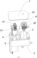
- an actuator provided in this embodiment includes a housing.
- the housing includes an upper housing 1 and a lower housing 2.
- An accommodation cavity 3 is formed between the upper housing 1 and the lower housing 2.
- a motor 4, a transmission mechanism 5, and a clutch mechanism 6 are arranged inside the accommodation cavity 3.
- a length of a side of the accommodation cavity 3 for accommodating the motor 4 is greater than a length of a side of the accommodation cavity 3 for accommodating the clutch mechanism 6.
- the transmission mechanism 5 is a worm wheel and worm.
- a worm 41 is arranged at an output end of the motor 4.
- a worm wheel end 51 of the transmission mechanism 5 is connected to the worm 41 in a transmission manner.
- a worm end 52 of the transmission mechanism is connected to a transmission member on the clutch mechanism 6 in a transmission manner.
- the transmission member is a transmission gear 61.
- An axis of the motor 4 and an axis of the transmission mechanism 5 are perpendicular to each other.
- the axis of the motor and an axis of a main shaft 62 of the clutch mechanism 6 are parallel to each other.
- the lower housing 2 is in an L-shape.
- the entire actuator is arranged in an L-shape, and is more suitable for the overall arrangement inside a vehicle body.
- the transmission mechanism 5 is not limited to the worm wheel and worm, but may alternatively be a pulley transmission mechanism, a gear set transmission mechanism, or another transmission mechanism capable of performing the same function.
- the worm wheel and worm is only one of the mechanisms.
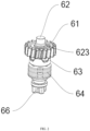
- the clutch mechanism 6 includes the main shaft 62 and a baffle 65.
- the transmission gear 61, a coupling 63, an elastic member 64, and the baffle 65 are sequentially sleeved along an axial direction of the main shaft 62.
- An output shaft 66 is fixed to the baffle 65.
- a first end of the main shaft 62 is in transmission cooperation to the transmission gear 61.
- a second end of the main shaft 62 is fixedly connected to the baffle 65.
- the transmission gear 61 rotates around the main shaft 62.
- a second end of the elastic member 64 abuts against the baffle 65.
- a first end of the elastic member 64 abuts against the coupling 63.
- the coupling 63 and the elastic member 64 are pressed between the transmission gear 61 and the baffle 65.
- the motor 4 drives the worm 41 to rotate
- the worm 41 drives the worm wheel end 51 to rotate
- the worm end 52 drives the transmission gear 61 to rotate
- the transmission gear 61 drives, by using the main shaft 62, the output shaft 66 to rotate.
- the transmission cooperation between the main shaft 62 and the transmission gear 61 is pin shaft fit.
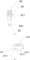
- the coupling 63 includes a first meshing portion 631 and a second meshing portion 632 meshing with each other.
- a transmission groove 633 is provided on the first meshing portion 631.
- a transmission shaft 621 is arranged on the main shaft 62. The transmission shaft 621 fits to the transmission groove 633.
- a first side of the first meshing portion 631 abuts against an end face of the elastic member 64.
- a second side of the second meshing portion 632 is fixed to an end face of a first side of the transmission gear 61.
- At least two first convex portions 6311 are arranged spaced away on the first meshing portion 631.
- a first concave portion 6312 is formed between adjacent first convex portions 6311.
- the second meshing portion 632 includes at least two second convex portions 6321 arranged spaced away.
- a second concave portion 6322 is formed between adjacent second convex portions 6321.
- the first convex portion 6311 fits to the second concave portion 6322.
- the second convex portion 6321 fits to the first concave portion 6312.
- the transmission gear 61 of the clutch mechanism 6 and the worm end 52 of the transmission mechanism 5 are in a self-locked state.
- the motor 4 can drive, by using the transmission mechanism 5, the transmission gear 61 to rotate, but in turn the output shaft 66 cannot reversely drive the worm end 52 of the transmission mechanism 5 by using the transmission gear 61.
- the charging port cover needs to be manually opened when the motor 4 fails to operate normally.
- the charging port cover is opened by hand, the charging port cover drives the output shaft 66 to rotate, and the output shaft 66 drives, by using the transmission shaft 621, the first meshing portion 631 to rotate.
- the second meshing portion 632 is fixed at an original position.
- the first meshing portion 631 rotates, the first meshing portion 631 is disengaged from the second meshing portion 632 due to relative movement of the first convex portion 6311 on a guide surface of a corresponding second convex portion 6321, to implement power decoupling of the output shaft 66 from the transmission mechanism 5. Therefore, the output shaft 66 can be driven to rotate by an external force, and the charging port cover can be opened manually.
- the elastic member causes the coupling 63 to abut against the transmission gear 61, and applies a pre-tightening force to the coupling 63, which is equivalent to pressing the coupling 63 tightly by the elastic member 64.
- a degree of external force is required to be applied to drive the coupling 63 to rotate to implement power decoupling between the output shaft 66 and the transmission mechanism 5.
- the output shaft 66 is not easily driven by mistake by an accidental external force in an emergency situation, and the charging port cover is not easily opened by mistake.
- a quantity of first convex portions 6311 is four and a quantity of second convex portions 6321 is four.
- a central angle formed between the adjacent first convex portions 6311 is 90°.
- the first meshing portion 631 and the second meshing portion 632 are re-coupled every time the output shaft 66 rotates by 90°. In this case, the first meshing portion 631 and the second meshing portion 632 are in a stable state, and the first meshing portion 631 and the second meshing portion 632 do not slip from each other.
- the charging port cover also rotates by 90°, so that a user inserts a charging connector directly into a charging port easily.
- a quantity of first convex portions 6311 is at least two and a quantity of second convex portions 6321 is at least two. If the quantity of first convex portions 6311 is two and the quantity of second convex portions 6321 is two, the output shaft needs to rotate by 180° to re-couple the first meshing portion 631 and the second meshing portion 632. A required rotation angle is excessively large. This solution can be theoretically implemented, but is less likely to be practically applied. When the quantity of first convex portions 6311 is three and the quantity of second convex portions 6321 is three, the output shaft needs to rotate by 120° to re-couple the first meshing portion 631 and the second meshing portion 632.
- the output shaft needs to rotate by 72° to re-couple the first meshing portion 631 and the second meshing portion 632.
- an opening of the charging port cover is excessively small, which does not facilitate insertion of the charging connector.
- the charging port cover needs to rotate by 72° again to re-couple the first meshing portion 631 and the second meshing portion 632, and the operation is inconvenient.
- the quantity of first convex portions 6311 may be set to three or four and the quantity of second convex portions 6321 may be set three or four.
- the elastic member 64 may be a disc spring, a wave spring, or a compression spring.
- the second end of the elastic member 64 abuts against the baffle 65.
- the first end of the elastic member 64 abuts against the coupling 63.
- the elastic member 64 is configured to apply the pre-tightening force to the coupling 63, cause the coupling 63 to abut against the transmission gear 61, and press the coupling 63 tightly.
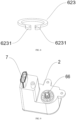
- a mounting groove 622 is provided on the main shaft 62.
- a retainer ring 623 is arranged inside the mounting groove 622.
- a stop portion 6231 is arranged on the retainer ring 623. The stop portion 6231 abuts against an end face of a second side that is of the transmission gear 61 and that is away from the second meshing portion 632.
- the stop portion 6231 abuts against the end face of the second side of the transmission gear 61 to implement a stopping function of the transmission gear 61 in the axial direction of the main shaft 62, to prevent the transmission gear 61 from slipping off the main shaft 62 during rotation.
- connection socket 7 is arranged on the lower housing 2, A cable in a vehicle is inserted into the connection socket 7.
- the cable transmits a start signal to the motor 4 through the connection socket 7, to drive the motor 4 to rotate and drive the charging port cover to open.
- a charging port cover provided in this embodiment includes the foregoing actuator and further includes a cap 8.
- a rotating shaft 81 is arranged on the cap 8. The rotating shaft 81 fits to the output shaft 66. When the output shaft 66 rotates, the rotating shaft 81 is also driven to rotate, so that the cap 8 is driven to turn over to expose a charging port. Then the charging connector is inserted for charging.
- a vehicle provided in this embodiment includes the foregoing charging port cover and further includes a sending device.
- the sending device is configured to send a start signal to the motor.
- the sending device is a cable.
- the connection socket 7 is arranged on the housing of the actuator.
- the cable is inserted into the connection socket 7.
- the start signal is sent to the charging port cover through a vehicle center control screen.
- the motor starts to rotate after receiving the start signal sent by the cable, to drive the cap 8 to rotate, to expose the charging port.
- a user inserts a charging connector into a charging port to charge the vehicle.
- the sending device is not limited to the cable, but may be another apparatus having the same function.
- orientation or position relationships indicated by the terms such as “center”, “longitudinal”, “transverse”, “length”, “width”, “thickness”, “on”, “below”, “front”, “back”, “left”, “right”, “vertical”, “horizontal”, “top”, “bottom”, “inside”, “outside”, “clockwise”, “anticlockwise”, “axial direction”, “radial direction”, and “circumferential direction” are based on orientation or position relationships shown in the accompanying drawings, and are used only for ease and brevity of description for the present disclosure, rather than indicating or implying that the mentioned apparatus or element must have a particular orientation or must be constructed and operated in a particular orientation. Therefore, such terms should not be construed as limiting of the present disclosure.
- first and second are used only for the purpose of description, and shall not be construed as indicating or implying relative importance or implying a quantity of indicated technical features. Therefore, a feature limited by “first” or “second” may explicitly or implicitly include one or more of the features. In the descriptions of the present disclosure, "a plurality of” means two or more, unless otherwise definitely and specifically limited.
- connection may be a fixed connection, a detachable connection, or an integral connection; or the connection may be a mechanical connection or an electrical connection; or the connection may be a direct connection, an indirect connection through an intermediary, or internal communication between two components.
- the first feature being located “above” or “below” the second feature may be the first feature being in a direct contact with the second feature, or the first feature being in an indirect contact with the second feature through an intermediary.
- the first feature is "above”, “over”, or “on” the second feature may indicate that the first feature is directly above or obliquely above the second feature, or may only indicate that the horizontal position of the first feature is higher than that of the second feature.
- That the first feature is "below”, “under”, and “beneath” the second feature may be that the first feature is right below the second feature or at an inclined bottom of the second feature, or may only indicate that the horizontal position of the first feature is lower than that of the second feature.
- a description of a reference term such as "an embodiment”, “some embodiments”, “an example”, “a specific example”, or “some examples” means that a specific feature, structure, material, or characteristic that is described with reference to the embodiment or the example is included in at least one embodiment or example of the present disclosure.
- exemplary descriptions of the foregoing terms do not necessarily refer to a same embodiment or example.
- the specific features, the structures, the materials, or the characteristics that are described may be combined in proper manners in any one or more embodiments or examples.
- a person skilled in the art may integrate or combine different embodiments or examples described in the specification and features of the different embodiments or examples as long as they are not contradictory to each other.
Landscapes
- Engineering & Computer Science (AREA)
- Mechanical Engineering (AREA)
- Transportation (AREA)
- Combustion & Propulsion (AREA)
- Chemical & Material Sciences (AREA)
- General Engineering & Computer Science (AREA)
- Power Engineering (AREA)
- Sustainable Energy (AREA)
- Sustainable Development (AREA)
- Life Sciences & Earth Sciences (AREA)
- Connection Of Motors, Electrical Generators, Mechanical Devices, And The Like (AREA)
- Electric Propulsion And Braking For Vehicles (AREA)
- Gear Transmission (AREA)
- Transmission Devices (AREA)
- Physics & Mathematics (AREA)
- Electromagnetism (AREA)
Abstract
Description
- This application claims priority to
Chinese Patent Application No. 202220769896.X, entitled "ACTUATOR, CHARGING PORT COVER, AND VEHICLE" and filed by BYD Co., Ltd. on March 31, 2022 - The present disclosure relates to the field of smart charging technologies, and specifically, to an actuator, a charging port cover, and a vehicle.
- Currently, most new energy vehicles on the market continue to use a manually opened charging port cover of fuel vehicles. For ease of control, some of the new energy vehicles use an automatically opened electric charging port cover. A commonly used control manner of the charging port cover is to automatically open the charging port cover by using a motor. To implement an emergency opening function, an internal structure of the electric charging port cover does not support a self-locking function, and a driver can directly open the charging port cover manually.
- However, when a vehicle turns sharply or brakes urgently, the electric charging port cover may be opened by mistake due to an excessive external force. To prevent the electric charging port cover from being opened by mistake due to the excessive external force, the electric charging port cover needs to have the self-locking function. However, this causes the electric charging port cover to not have the emergency opening function. Currently, this problem cannot be resolved for the electric charging port cover.
- The present disclosure is intended to resolve one of technical problems in the related art at least to some extent.
- The present disclosure provides an actuator.
- The actuator according to the present disclosure includes a motor, a transmission mechanism, a clutch mechanism, and an output shaft. The motor is connected to the clutch mechanism in a transmission manner through the transmission mechanism. The clutch mechanism is connected to the output shaft. The transmission mechanism is power-coupled to the output shaft by using the clutch mechanism when the motor drives the output shaft to rotate. The transmission mechanism is power-decoupled from the output shaft by using the clutch mechanism when an external force drives the output shaft to rotate.
- Therefore, a charging port cover including the foregoing actuator has a function of preventing the charging port cover from being opened by mistake. A user needs to apply an external force to manually open the charging port cover when the motor fails and the charging port cover cannot be normally opened, to effectively prevent the charging port cover from being opened by mistake due to an accidental external force.
- The present disclosure further provides a charging port cover. The charging port cover includes the foregoing actuator. The charging port cover further includes a cap. A rotating shaft of the cap fits to an output shaft.
- The present disclosure further provides a vehicle. The vehicle includes the foregoing charging port cover and a sending device. The sending device is configured to send a start signal to the motor.
- Other aspects and advantages of the present disclosure will be given in the following descriptions, some of which will become apparent from the following descriptions or may be learned from practices of the present disclosure.
-
-
FIG. 1 is an exploded view of an actuator according to an embodiment of the present disclosure; -
FIG. 2 is a first view of a clutch mechanism according to an embodiment of the present disclosure; -
FIG. 3 is a second view of a clutch mechanism according to an embodiment of the present disclosure; -
FIG. 4 is a schematic partial structural diagram of a clutch mechanism according to an embodiment of the present disclosure; -
FIG. 5 is a schematic structural diagram of a first meshing portion according to an embodiment of the present disclosure; -
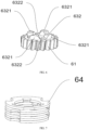
FIG. 6 is a schematic structural diagram of a transmission gear according to an embodiment of the present disclosure; -
FIG. 7 is a structural diagram of an elastic member according to an embodiment of the present disclosure; -
FIG. 8 is a structural diagram of a retainer ring according to an embodiment of the present disclosure; -
FIG. 9 is a structural diagram of an actuator according to an embodiment of the present disclosure; and -
FIG. 10 is a structural diagram of a charging port cover according to an embodiment of the present disclosure. - Embodiments of the present disclosure are described in detail below, and examples of the embodiments are shown in the accompanying drawings, where the same or similar elements or the elements having the same or similar functions are denoted by the same or similar reference numerals throughout the accompanying drawings. The embodiments described below with reference to the accompanying drawings are exemplary, and are intended to explain the present disclosure and cannot be construed as a limitation to the present disclosure.
- Referring to
FIG. 1 , an actuator provided in this embodiment includes a housing. The housing includes anupper housing 1 and alower housing 2. Anaccommodation cavity 3 is formed between theupper housing 1 and thelower housing 2. Amotor 4, atransmission mechanism 5, and aclutch mechanism 6 are arranged inside theaccommodation cavity 3. A length of a side of theaccommodation cavity 3 for accommodating themotor 4 is greater than a length of a side of theaccommodation cavity 3 for accommodating theclutch mechanism 6. Thetransmission mechanism 5 is a worm wheel and worm. Aworm 41 is arranged at an output end of themotor 4. Aworm wheel end 51 of thetransmission mechanism 5 is connected to theworm 41 in a transmission manner. Aworm end 52 of the transmission mechanism is connected to a transmission member on theclutch mechanism 6 in a transmission manner. The transmission member is atransmission gear 61. An axis of themotor 4 and an axis of thetransmission mechanism 5 are perpendicular to each other. The axis of the motor and an axis of amain shaft 62 of theclutch mechanism 6 are parallel to each other. Thelower housing 2 is in an L-shape. The entire actuator is arranged in an L-shape, and is more suitable for the overall arrangement inside a vehicle body. Certainly, thetransmission mechanism 5 is not limited to the worm wheel and worm, but may alternatively be a pulley transmission mechanism, a gear set transmission mechanism, or another transmission mechanism capable of performing the same function. The worm wheel and worm is only one of the mechanisms. - Referring to
FIG. 2 andFIG. 3 , theclutch mechanism 6 includes themain shaft 62 and abaffle 65. Thetransmission gear 61, acoupling 63, anelastic member 64, and thebaffle 65 are sequentially sleeved along an axial direction of themain shaft 62. Anoutput shaft 66 is fixed to thebaffle 65. A first end of themain shaft 62 is in transmission cooperation to thetransmission gear 61. A second end of themain shaft 62 is fixedly connected to thebaffle 65. Thetransmission gear 61 rotates around themain shaft 62. A second end of theelastic member 64 abuts against thebaffle 65. A first end of theelastic member 64 abuts against thecoupling 63. Thecoupling 63 and theelastic member 64 are pressed between thetransmission gear 61 and thebaffle 65. When themotor 4 drives theworm 41 to rotate, theworm 41 drives theworm wheel end 51 to rotate, theworm end 52 drives thetransmission gear 61 to rotate, and thetransmission gear 61 drives, by using themain shaft 62, theoutput shaft 66 to rotate. In this embodiment, the transmission cooperation between themain shaft 62 and thetransmission gear 61 is pin shaft fit. - Referring to
FIG. 4 to FIG. 6 , thecoupling 63 includes afirst meshing portion 631 and asecond meshing portion 632 meshing with each other. Atransmission groove 633 is provided on thefirst meshing portion 631. Atransmission shaft 621 is arranged on themain shaft 62. Thetransmission shaft 621 fits to thetransmission groove 633. A first side of thefirst meshing portion 631 abuts against an end face of theelastic member 64. A second side of thesecond meshing portion 632 is fixed to an end face of a first side of thetransmission gear 61. At least two firstconvex portions 6311 are arranged spaced away on thefirst meshing portion 631. A firstconcave portion 6312 is formed between adjacent firstconvex portions 6311. Thesecond meshing portion 632 includes at least two secondconvex portions 6321 arranged spaced away. A secondconcave portion 6322 is formed between adjacent secondconvex portions 6321. The firstconvex portion 6311 fits to the secondconcave portion 6322. The secondconvex portion 6321 fits to the firstconcave portion 6312. - In this embodiment, to prevent a charging port cover from being opened by mistake, the
transmission gear 61 of theclutch mechanism 6 and theworm end 52 of thetransmission mechanism 5 are in a self-locked state. In other words, themotor 4 can drive, by using thetransmission mechanism 5, thetransmission gear 61 to rotate, but in turn theoutput shaft 66 cannot reversely drive theworm end 52 of thetransmission mechanism 5 by using thetransmission gear 61. The charging port cover needs to be manually opened when themotor 4 fails to operate normally. The charging port cover is opened by hand, the charging port cover drives theoutput shaft 66 to rotate, and theoutput shaft 66 drives, by using thetransmission shaft 621, thefirst meshing portion 631 to rotate. Because thetransmission gear 61 and theworm end 52 are in the self-locked state, and thesecond meshing portion 632 is fixed to thetransmission gear 61, thesecond meshing portion 632 is fixed at an original position. When thefirst meshing portion 631 rotates, thefirst meshing portion 631 is disengaged from thesecond meshing portion 632 due to relative movement of the firstconvex portion 6311 on a guide surface of a corresponding secondconvex portion 6321, to implement power decoupling of theoutput shaft 66 from thetransmission mechanism 5. Therefore, theoutput shaft 66 can be driven to rotate by an external force, and the charging port cover can be opened manually. In addition, the elastic member causes thecoupling 63 to abut against thetransmission gear 61, and applies a pre-tightening force to thecoupling 63, which is equivalent to pressing thecoupling 63 tightly by theelastic member 64. When an external force is required to drive thecoupling 63 to rotate, a degree of external force is required to be applied to drive thecoupling 63 to rotate to implement power decoupling between theoutput shaft 66 and thetransmission mechanism 5. In this case, theoutput shaft 66 is not easily driven by mistake by an accidental external force in an emergency situation, and the charging port cover is not easily opened by mistake. - In this embodiment, a quantity of first
convex portions 6311 is four and a quantity of secondconvex portions 6321 is four. A central angle formed between the adjacent firstconvex portions 6311 is 90°. Thefirst meshing portion 631 and thesecond meshing portion 632 are re-coupled every time theoutput shaft 66 rotates by 90°. In this case, thefirst meshing portion 631 and thesecond meshing portion 632 are in a stable state, and thefirst meshing portion 631 and thesecond meshing portion 632 do not slip from each other. The charging port cover also rotates by 90°, so that a user inserts a charging connector directly into a charging port easily. - It should be noted that a quantity of first
convex portions 6311 is at least two and a quantity of secondconvex portions 6321 is at least two. If the quantity of firstconvex portions 6311 is two and the quantity of secondconvex portions 6321 is two, the output shaft needs to rotate by 180° to re-couple thefirst meshing portion 631 and thesecond meshing portion 632. A required rotation angle is excessively large. This solution can be theoretically implemented, but is less likely to be practically applied. When the quantity of firstconvex portions 6311 is three and the quantity of secondconvex portions 6321 is three, the output shaft needs to rotate by 120° to re-couple thefirst meshing portion 631 and thesecond meshing portion 632. When the quantity of firstconvex portions 6311 is five and the quantity of secondconvex portions 6321 is five, the output shaft needs to rotate by 72° to re-couple thefirst meshing portion 631 and thesecond meshing portion 632. However, an opening of the charging port cover is excessively small, which does not facilitate insertion of the charging connector. In this case, the charging port cover needs to rotate by 72° again to re-couple thefirst meshing portion 631 and thesecond meshing portion 632, and the operation is inconvenient. In conclusion, the quantity of firstconvex portions 6311 may be set to three or four and the quantity of secondconvex portions 6321 may be set three or four. - Referring to
FIG. 7 , theelastic member 64 may be a disc spring, a wave spring, or a compression spring. The second end of theelastic member 64 abuts against thebaffle 65. The first end of theelastic member 64 abuts against thecoupling 63. Theelastic member 64 is configured to apply the pre-tightening force to thecoupling 63, cause thecoupling 63 to abut against thetransmission gear 61, and press thecoupling 63 tightly. - Referring to
FIG. 4 andFIG. 8 , a mountinggroove 622 is provided on themain shaft 62. Aretainer ring 623 is arranged inside the mountinggroove 622. Astop portion 6231 is arranged on theretainer ring 623. Thestop portion 6231 abuts against an end face of a second side that is of thetransmission gear 61 and that is away from thesecond meshing portion 632. - In the foregoing solution, the
stop portion 6231 abuts against the end face of the second side of thetransmission gear 61 to implement a stopping function of thetransmission gear 61 in the axial direction of themain shaft 62, to prevent thetransmission gear 61 from slipping off themain shaft 62 during rotation. - Referring to
FIG. 9 , aconnection socket 7 is arranged on thelower housing 2, A cable in a vehicle is inserted into theconnection socket 7. The cable transmits a start signal to themotor 4 through theconnection socket 7, to drive themotor 4 to rotate and drive the charging port cover to open. - Referring to
FIG. 10 , a charging port cover provided in this embodiment includes the foregoing actuator and further includes acap 8. A rotatingshaft 81 is arranged on thecap 8. The rotatingshaft 81 fits to theoutput shaft 66. When theoutput shaft 66 rotates, the rotatingshaft 81 is also driven to rotate, so that thecap 8 is driven to turn over to expose a charging port. Then the charging connector is inserted for charging. - A vehicle provided in this embodiment includes the foregoing charging port cover and further includes a sending device. The sending device is configured to send a start signal to the motor.
- In this embodiment, the sending device is a cable. The
connection socket 7 is arranged on the housing of the actuator. The cable is inserted into theconnection socket 7. When the charging port cover needs to be opened, the start signal is sent to the charging port cover through a vehicle center control screen. The motor starts to rotate after receiving the start signal sent by the cable, to drive thecap 8 to rotate, to expose the charging port. In this case, a user inserts a charging connector into a charging port to charge the vehicle. The sending device is not limited to the cable, but may be another apparatus having the same function. - In the descriptions of the present disclosure, it should be understood that orientation or position relationships indicated by the terms such as "center", "longitudinal", "transverse", "length", "width", "thickness", "on", "below", "front", "back", "left", "right", "vertical", "horizontal", "top", "bottom", "inside", "outside", "clockwise", "anticlockwise", "axial direction", "radial direction", and "circumferential direction" are based on orientation or position relationships shown in the accompanying drawings, and are used only for ease and brevity of description for the present disclosure, rather than indicating or implying that the mentioned apparatus or element must have a particular orientation or must be constructed and operated in a particular orientation. Therefore, such terms should not be construed as limiting of the present disclosure.
- In addition, terms "first" and "second" are used only for the purpose of description, and shall not be construed as indicating or implying relative importance or implying a quantity of indicated technical features. Therefore, a feature limited by "first" or "second" may explicitly or implicitly include one or more of the features. In the descriptions of the present disclosure, "a plurality of" means two or more, unless otherwise definitely and specifically limited.
- In the descriptions of the present disclosure, unless otherwise explicitly specified or defined, the terms such as "mount", "install", "connect", and "connection" should be understood in a broad sense. For example, the connection may be a fixed connection, a detachable connection, or an integral connection; or the connection may be a mechanical connection or an electrical connection; or the connection may be a direct connection, an indirect connection through an intermediary, or internal communication between two components. A person of ordinary skill in the art may understand the specific meanings of the foregoing terms in the present disclosure according to specific situations.
- In the present disclosure, unless otherwise explicitly specified or defined, the first feature being located "above" or "below" the second feature may be the first feature being in a direct contact with the second feature, or the first feature being in an indirect contact with the second feature through an intermediary. In addition, that the first feature is "above", "over", or "on" the second feature may indicate that the first feature is directly above or obliquely above the second feature, or may only indicate that the horizontal position of the first feature is higher than that of the second feature. That the first feature is "below", "under", and "beneath" the second feature may be that the first feature is right below the second feature or at an inclined bottom of the second feature, or may only indicate that the horizontal position of the first feature is lower than that of the second feature.
- In the descriptions of this specification, a description of a reference term such as "an embodiment", "some embodiments", "an example", "a specific example", or "some examples" means that a specific feature, structure, material, or characteristic that is described with reference to the embodiment or the example is included in at least one embodiment or example of the present disclosure. In this specification, exemplary descriptions of the foregoing terms do not necessarily refer to a same embodiment or example. Besides, the specific features, the structures, the materials, or the characteristics that are described may be combined in proper manners in any one or more embodiments or examples. In addition, a person skilled in the art may integrate or combine different embodiments or examples described in the specification and features of the different embodiments or examples as long as they are not contradictory to each other.
- Although embodiments of the present disclosure are shown and described above, it can be understood that, the foregoing embodiments are exemplary, and cannot be construed as a limitation to the present disclosure. Within the scope of the present disclosure, a person of ordinary skill in the art may make changes, modifications, replacement, and variations to the foregoing embodiments.
Claims (15)
- An actuator, comprising a motor, a transmission mechanism, a clutch mechanism, and an output shaft, the motor being connected to the clutch mechanism in a transmission manner through the transmission mechanism, the clutch mechanism being connected to the output shaft; the transmission mechanism being power-coupled to the output shaft by using the clutch mechanism when the motor drives the output shaft to rotate; and the transmission mechanism being power-decoupled from the output shaft by using the clutch mechanism when an external force drives the output shaft to rotate.
- The actuator according to claim 1, wherein
the clutch mechanism comprises a main shaft and a baffle, a transmission gear, a coupling, and an elastic member are sequentially sleeved along an axial direction of the main shaft, a first end of the main shaft is in transmission cooperation to the transmission gear, a second end of the main shaft is fixedly connected to the baffle, and the coupling and the elastic member are pressed between the transmission gear and the baffle. - The actuator according to claim 2, wherein
the coupling comprises a first meshing portion and a second meshing portion that fit to each other, a first side of the first meshing portion abuts against an end face of the elastic member, and a second side of the second meshing portion is fixed to an end face of a first side of the transmission gear. - The actuator according to claim 3, wherein
the first meshing portion comprises at least two first convex portions arranged spaced away, a first concave portion is formed between adjacent first convex portions, the second meshing portion comprises at least two second convex portions arranged spaced away, a second concave portion is formed between adjacent second convex portions, the first convex portion fits to the second concave portion, and the second convex portion fits to the first concave portion. - The actuator according to claim 4, wherein
the first convex portion and the second convex portion are in an isosceles trapezoid or a circular arc. - The actuator according to any one of claims 3 to 5, wherein
a transmission groove is provided on the first meshing portion, a transmission shaft is arranged on the main shaft, and the transmission shaft is in transmission cooperation to the transmission groove. - The actuator according to any one of claims 3 to 6, wherein
a mounting groove is provided on the main shaft, a retainer ring is arranged inside the mounting groove, a stop portion is arranged on the retainer ring, and the stop portion abuts against an end face of a second side that is of the transmission gear and that is away from the second meshing portion. - The actuator according to any one of claims 4 to 7, wherein
the first meshing portion comprises four first convex portions arranged spaced away, the first concave portion is formed between the adjacent first convex portions, the second meshing portion comprises four second convex portions arranged spaced away, the second concave portion is formed between the adjacent second convex portions, the first convex portion fits to the second concave portion, and the second convex portion fits to the first concave portion. - The actuator according to any one of claims 2 to 8, wherein
the transmission mechanism is a worm wheel and worm, a worm is arranged at an output end of the motor, a worm wheel end of the worm wheel and worm is connected to the worm in a transmission manner, and a worm end of the worm wheel and worm is connected to the transmission gear in a transmission manner. - The actuator according to any one of claims 1 to 9, wherein
an axis of the motor and an axis of the transmission mechanism are perpendicular to each other, and the axis of the motor and an axis of the clutch mechanism are parallel to each other. - The actuator according to any one of claims 1 to 10,
further comprising a housing, the housing comprising an upper housing and a lower housing, an accommodation cavity being formed between the upper housing and the lower housing, and the motor, the transmission mechanism, and the clutch mechanism being arranged inside the accommodation cavity. - The actuator according to claim 11, wherein
the lower housing is in an L-shape. - A charging port cover, comprising the actuator according to any one of claims 1 to 12, and further comprising a cap, and a rotating shaft of the cap fits to the output shaft.
- The charging port cover according to claim 13, wherein
the transmission mechanism is power-coupled to the cap by using the clutch mechanism when the motor drives the cap to rotate; and the transmission mechanism is power-decoupled from the cap by using the clutch mechanism when an external force drives the cap to rotate. - A vehicle, comprising the charging port cover according to claim 13 or 14, and
comprising a sending device, the sending device being configured to send a start signal to the motor.
Applications Claiming Priority (2)
| Application Number | Priority Date | Filing Date | Title |
|---|---|---|---|
| CN202220769896.XU CN217994596U (en) | 2022-03-31 | 2022-03-31 | Executor, charging port cover and vehicle |
| PCT/CN2023/084221 WO2023185783A1 (en) | 2022-03-31 | 2023-03-28 | Actuator, charge port cover, and vehicle |
Publications (2)
| Publication Number | Publication Date |
|---|---|
| EP4434856A1 true EP4434856A1 (en) | 2024-09-25 |
| EP4434856A4 EP4434856A4 (en) | 2025-04-16 |
Family
ID=84287781
Family Applications (1)
| Application Number | Title | Priority Date | Filing Date |
|---|---|---|---|
| EP23778148.9A Pending EP4434856A4 (en) | 2022-03-31 | 2023-03-28 | Actuator, charge port cover, and vehicle |
Country Status (6)
| Country | Link |
|---|---|
| US (1) | US20240352980A1 (en) |
| EP (1) | EP4434856A4 (en) |
| JP (1) | JP2025510456A (en) |
| KR (1) | KR20240118114A (en) |
| CN (1) | CN217994596U (en) |
| WO (1) | WO2023185783A1 (en) |
Families Citing this family (8)
| Publication number | Priority date | Publication date | Assignee | Title |
|---|---|---|---|---|
| CN217994596U (en) * | 2022-03-31 | 2022-12-09 | 比亚迪股份有限公司 | Executor, charging port cover and vehicle |
| US20230374842A1 (en) * | 2022-05-17 | 2023-11-23 | Illinois Tool Works Inc. | Overload Clutch for an Actuator for Driving Components of a Loading, Fueling or Service Door, and Actuating Mechanism for Operating a Loading, Fueling or Service Door Including such an Overload Clutch |
| KR102689427B1 (en) * | 2022-09-16 | 2024-07-26 | 장은숙 | Complex clutch device |
| US20240246409A1 (en) * | 2023-01-25 | 2024-07-25 | Magna Mirrors Of America, Inc. | Vehicular charge port cover system |
| CN117145340B (en) * | 2023-09-12 | 2026-03-13 | 宁波精华电子科技股份有限公司 | A car charging door actuator |
| CN221169178U (en) * | 2023-09-28 | 2024-06-18 | 比亚迪股份有限公司 | Cover plate opening and closing actuator and vehicle |
| CN120663767B (en) * | 2025-07-01 | 2026-04-07 | 伟速达(中国)汽车安全系统有限公司 | Charging flap |
| CN120626013B (en) * | 2025-08-13 | 2025-12-09 | 宁波华楷电子科技有限公司 | Electric automobile flap actuating mechanism with ice breaking function |
Family Cites Families (18)
| Publication number | Priority date | Publication date | Assignee | Title |
|---|---|---|---|---|
| JP6496718B2 (en) * | 2013-06-19 | 2019-04-03 | マグナ インターナショナル インコーポレイテッド | Sealed actuator with internal clutch |
| KR101620736B1 (en) * | 2013-12-02 | 2016-05-12 | 가부시키가이샤 니프코 | Lid device |
| CN207278788U (en) * | 2017-09-28 | 2018-04-27 | 裕克施乐塑料制品(太仓)有限公司 | A kind of actuator of electromagnetic sucker type |
| CN109306696A (en) * | 2018-10-23 | 2019-02-05 | 马鞍山宏泰建材股份有限公司 | Square pile structure |
| CN109435640A (en) * | 2018-11-13 | 2019-03-08 | 宁波精华电子科技股份有限公司 | A kind of auto-manual actuator |
| JP7047746B2 (en) * | 2018-12-17 | 2022-04-05 | トヨタ自動車株式会社 | Vehicle control unit |
| CN209687174U (en) * | 2019-02-19 | 2019-11-26 | 南京中竞科电子科技有限公司 | A kind of refrigerator of the automatic door operator with clutch |
| CN211448268U (en) * | 2019-12-19 | 2020-09-08 | 宁波依诺汽车电子有限公司 | Automatic opening and closing actuator and automatic opening and closing device for electric vehicle charging cover |
| CN112127735B (en) * | 2020-09-09 | 2022-05-13 | 重庆海德世拉索系统(集团)有限公司 | Opening and closing driving device for energy source opening cover of automobile body |
| CN112503151B (en) * | 2020-12-14 | 2024-01-05 | 裕克施乐塑料制品(太仓)有限公司 | Mechanical bidirectional clutch manual-automatic rotary actuator with torque induction protection function |
| CN214699002U (en) * | 2021-02-09 | 2021-11-12 | 江苏雷利电机股份有限公司 | Automobile air conditioner actuator |
| CN112943003B (en) * | 2021-03-19 | 2024-08-13 | 宁波华楷电子科技有限公司 | Electric small door actuator assembly on automobile-used fuel tank cap or charging box cap |
| CN216519422U (en) * | 2021-08-26 | 2022-05-13 | 比亚迪股份有限公司 | A driving device and vehicle |
| CN113864403B (en) * | 2021-10-19 | 2024-07-16 | 东莞皓永汽车配件有限公司 | Cover plate driving device of automobile |
| CN114541914B (en) * | 2022-02-11 | 2024-05-03 | 海信冰箱有限公司 | Refrigerator with a refrigerator body |
| CN217994596U (en) * | 2022-03-31 | 2022-12-09 | 比亚迪股份有限公司 | Executor, charging port cover and vehicle |
| CN217381533U (en) * | 2022-04-28 | 2022-09-06 | 比亚迪股份有限公司 | Drive device and vehicle |
| CN217893039U (en) * | 2022-08-17 | 2022-11-25 | 宁波精成车业有限公司 | Automobile charging cover actuator |
-
2022
- 2022-03-31 CN CN202220769896.XU patent/CN217994596U/en active Active
-
2023
- 2023-03-28 EP EP23778148.9A patent/EP4434856A4/en active Pending
- 2023-03-28 KR KR1020247021721A patent/KR20240118114A/en not_active Ceased
- 2023-03-28 JP JP2024538772A patent/JP2025510456A/en active Pending
- 2023-03-28 WO PCT/CN2023/084221 patent/WO2023185783A1/en not_active Ceased
-
2024
- 2024-06-28 US US18/757,871 patent/US20240352980A1/en not_active Abandoned
Also Published As
| Publication number | Publication date |
|---|---|
| US20240352980A1 (en) | 2024-10-24 |
| WO2023185783A1 (en) | 2023-10-05 |
| KR20240118114A (en) | 2024-08-02 |
| EP4434856A4 (en) | 2025-04-16 |
| JP2025510456A (en) | 2025-04-15 |
| CN217994596U (en) | 2022-12-09 |
Similar Documents
| Publication | Publication Date | Title |
|---|---|---|
| US20240352980A1 (en) | Actuator, charging port cover, and vehicle | |
| US5368954A (en) | Device on electric power hand tools | |
| CN108631122B (en) | Actuator | |
| CN110316105B (en) | Wire harness connector, display device and vehicle | |
| WO2013125573A1 (en) | Cable housing device | |
| CN209067039U (en) | Driving body and smart lock driver | |
| WO2025066343A1 (en) | Cover plate opening-and-closing actuator, and vehicle | |
| CN217381533U (en) | Drive device and vehicle | |
| CN120393187A (en) | Syringe Pump | |
| CN218408386U (en) | Transmission mechanism and equipment | |
| US4006489A (en) | Film rewinder mountable on camera | |
| CN211404426U (en) | Reclosing device of circuit breaker | |
| CN219376054U (en) | Rotary driving toy | |
| EP1855359A1 (en) | Connector device and electronic device | |
| CN218220735U (en) | Clamping device and injection pump | |
| CN210970386U (en) | Seal module locking mechanism and seal control instrument | |
| CN115206739A (en) | Switching-on and switching-off operating mechanism and circuit breaker | |
| CN218011032U (en) | Toy car driving module | |
| JP2001224145A (en) | Motor fixing structure | |
| CN119975509B (en) | Steering column adjustment mechanism, steering system and vehicle | |
| CN115251910A (en) | A safety self-locking needle aid | |
| CN222628972U (en) | Printer cover opening structure | |
| CN219213042U (en) | Electric tool | |
| JPS6157642B2 (en) | ||
| CN115275670B (en) | Power adapters and electronic equipment components |
Legal Events
| Date | Code | Title | Description |
|---|---|---|---|
| STAA | Information on the status of an ep patent application or granted ep patent |
Free format text: STATUS: THE INTERNATIONAL PUBLICATION HAS BEEN MADE |
|
| PUAI | Public reference made under article 153(3) epc to a published international application that has entered the european phase |
Free format text: ORIGINAL CODE: 0009012 |
|
| STAA | Information on the status of an ep patent application or granted ep patent |
Free format text: STATUS: REQUEST FOR EXAMINATION WAS MADE |
|
| 17P | Request for examination filed |
Effective date: 20240619 |
|
| AK | Designated contracting states |
Kind code of ref document: A1 Designated state(s): AL AT BE BG CH CY CZ DE DK EE ES FI FR GB GR HR HU IE IS IT LI LT LU LV MC ME MK MT NL NO PL PT RO RS SE SI SK SM TR |
|
| A4 | Supplementary search report drawn up and despatched |
Effective date: 20250314 |
|
| RIC1 | Information provided on ipc code assigned before grant |
Ipc: B60K 15/05 20060101ALI20250310BHEP Ipc: E05B 85/00 20140101ALI20250310BHEP Ipc: E05B 83/24 20140101ALI20250310BHEP Ipc: E05B 81/06 20140101ALI20250310BHEP Ipc: B62D 25/24 20060101AFI20250310BHEP |
|
| DAV | Request for validation of the european patent (deleted) | ||
| DAX | Request for extension of the european patent (deleted) |