EP4434853A1 - Vehicle structure - Google Patents
Vehicle structure Download PDFInfo
- Publication number
- EP4434853A1 EP4434853A1 EP24150130.3A EP24150130A EP4434853A1 EP 4434853 A1 EP4434853 A1 EP 4434853A1 EP 24150130 A EP24150130 A EP 24150130A EP 4434853 A1 EP4434853 A1 EP 4434853A1
- Authority
- EP
- European Patent Office
- Prior art keywords
- vehicle
- dash
- panel
- extension
- width direction
- Prior art date
- Legal status (The legal status is an assumption and is not a legal conclusion. Google has not performed a legal analysis and makes no representation as to the accuracy of the status listed.)
- Pending
Links
- 230000035939 shock Effects 0.000 claims description 17
- 230000002787 reinforcement Effects 0.000 claims description 8
- 239000000463 material Substances 0.000 description 13
- 238000003466 welding Methods 0.000 description 7
- 239000011324 bead Substances 0.000 description 5
- 238000010521 absorption reaction Methods 0.000 description 2
- 238000005452 bending Methods 0.000 description 1
- 230000007423 decrease Effects 0.000 description 1
- 238000010586 diagram Methods 0.000 description 1
- 230000000694 effects Effects 0.000 description 1
- 238000003780 insertion Methods 0.000 description 1
- 230000037431 insertion Effects 0.000 description 1
- 238000012986 modification Methods 0.000 description 1
- 230000004048 modification Effects 0.000 description 1
- 238000000638 solvent extraction Methods 0.000 description 1
- 239000000725 suspension Substances 0.000 description 1
Images


Classifications
-
- B—PERFORMING OPERATIONS; TRANSPORTING
- B62—LAND VEHICLES FOR TRAVELLING OTHERWISE THAN ON RAILS
- B62D—MOTOR VEHICLES; TRAILERS
- B62D25/00—Superstructure or monocoque structure sub-units; Parts or details thereof not otherwise provided for
- B62D25/08—Front or rear portions
Definitions
- the present invention relates to a vehicle structure including a dash panel and floor side members.
- floor side members extending in the vehicle front-rear direction and constituting a part of a vehicle body frame are disposed.
- the floor side members extend in the vehicle front-rear direction and have particularly high strength against an input load in the axial direction of the floor side members.
- Patent Literature 1 As an example of the vehicle structure including the floor side members described above, a structure disclosed in Patent Literature 1 is known.
- a first front side member is provided, in the vehicle front of side members functioning as the floor side members, coaxially with the side members and projects forward, and furthermore, a second front side member projects to the vehicle front on the vehicle width direction outer side of the first front side member.
- Patent Literature 1 in a collision such as offset collision in which obstacles in front of the vehicle collide with the vehicle front portion, parts of the obstacles are crushed at the front ends of small areas of the front side members projecting to the vehicle front and, thereafter, the remaining portions of the obstacles directly enter the vehicle body. Therefore, in the collision such as the offset collision, it is likely that collision energy can be input to the vehicle body while energy absorption remains insufficient, and there is room of improvement.
- an object of the present invention is to provide a vehicle structure that can effectively reduce collision energy input to a vehicle body in collision such as front collision.
- a vehicle structure including: a dash panel provided in a vehicle front portion; and a floor side member provided in a vehicle width direction outer side portion of a lower surface of a floor panel of a vehicle and extending in a vehicle front-rear direction.
- the vehicle structure includes: a dash side panel extending in the vehicle front-rear direction from a vehicle width direction outer side portion of the dash panel; a dash side frame extending to a vehicle front from the dash side panel and located further on an outer side than the floor side member in a vehicle width direction; a longitudinal member covering a front end of the floor side member from a front and extending in a vehicle up-down direction; an extension frame extending forwardly downward from the dash side frame to a position separated to a vehicle width direction outer side with respect to the longitudinal member; and a shield wall member having a front surface extending from the extension frame to the longitudinal member and facing the vehicle front, the shield wall member being joined to the extension frame and the longitudinal member.
- the present invention it is possible to provide a vehicle structure that can effectively reduce collision energy input to a vehicle body in a collision such as a front collision.
- Figure 1 and Figure 2 are diagrams for describing a vehicle structure 100 according to the embodiment of the present invention.
- Figure 1 is a perspective view viewed from the vehicle front.
- Figure 2 is a perspective view viewed from the vehicle front at another angle.
- an arrow Fr direction indicates the front in the vehicle front-rear direction
- an arrow U direction indicates the vehicle upward direction in the vehicle up-down direction.
- a front portion (a front end) and a rear portion (a rear end)” in the description of the embodiment correspond to a front portion and a rear portion in the vehicle front-rear direction.
- Arrows L and R directions indicate the left side and the right side in the vehicle width direction.
- Left and right in the description of this embodiment correspond to the left and the right at the time when an occupant in a vehicle interior faces the vehicle front.
- the vehicle structure 100 in this embodiment is mainly applied to a vehicle front portion and a vehicle bottom portion.
- a vehicle to which the vehicle structure 100 is applied is a small vehicle having a relatively short dimension in the vehicle front-rear direction of the vehicle front portion (specifically, a portion from a dash panel 10 described below to a front bumper, not shown).
- a portion including a right front wheel of the vehicle in the vehicle structure 100 is shown.
- a portion including a left front wheel of the vehicle structure 100 is the same structure as the portion including the right front wheel except that the portion including the left front wheel is symmetrical with respect to the portion including the right front wheel. Illustration of the portion including the left front wheel is omitted.
- the vehicle to which the vehicle structure 100 is applied is an electric vehicle.
- a battery, not shown, and as electric motor, not shown, for vehicle traveling are mounted on the vehicle.
- the electric motor operates with electric power supplied from the battery.
- the electric vehicle is generally heavier than the engine driven vehicle if vehicle sizes are the same.
- the vehicle structure 100 in this embodiment includes a dash panel 10, a dash side panel 11, a dash cross member 12, a wheelhouse 20, a floor side member 30, and a dash side frame 40.
- the dash panel 10 is provided in a vehicle front portion.
- the dash panel 10 is, for example, a panel material partitioning a front unit compartment R1 and an occupant compartment and generally extends in the vehicle width direction and the vehicle up-down direction.
- driving devices such as an engine and an electric motor (in this embodiment, the electric motor) and the like are disposed.
- An upper portion of a portion including a vehicle width direction outer side portion of the dash panel 10 constitutes a retracting part 10a bent to retract to the vehicle rear.
- the front unit compartment R1 is called a power unit compartment as well and is formed mainly by the dash panel 10, a front bumper extending in the vehicle width direction at the not-shown vehicle front end and a not-shown front hood extending from the upper end portion of the dash panel 10 to the upper end portion of the front bumper.
- the dash side panel 11 is provided in the vehicle width direction outer side portion of the dash panel 10 and located above a front wheel W.
- the dash side panel 11 is a panel material joined to an upper side portion of the vehicle width direction outer side portion of the dash panel 10 and extends in the vehicle front-rear direction from the vehicle width direction outer side portion of the dash panel 10.
- the dash side panel 11 includes a first side panel part 1 1a joined to the vehicle width direction outer side portion of the dash panel 10 and facing the vehicle width direction outer side, a second side panel part 11b generally projecting to the vehicle width direction inner side from the front end of the first side panel part 11a and facing the vehicle front side, and a third side panel part 11c projecting to the vehicle front from the vehicle width direction inner end of the second side panel part 11b and facing the vehicle width direction outer side.
- the second side panel part 11b is inclined such that the inner end of the second side panel part 11b is located further in the vehicle front than the outer end of the second side panel part 11b in the vehicle width direction.
- the second side panel part 11b and the third side panel part 11c are located further in the vehicle front than the retracting part 10a of the dash panel 10.
- the cross member outer side part 12b is generally formed in an L shape in plan view viewed from the vehicle up-down direction and formed to extend along the retracting part 10a of the dash panel 10.
- a vehicle width direction outer side portion of the cross member outer side part 12b is opened to the vehicle width direction outer side.
- the wheelhouse 20 is a panel material covering the front wheel W of the vehicle from above and is joined to a lower side portion in the vehicle width direction outer side portion of the dash panel 10.
- the wheelhouse 20 includes a wheelhouse main body panel 21, a strut tower 22, and a wheelhouse extension panel 23.
- the strut tower 22 is a structure including a panel material for attaching an upper portion of a strut (not shown) extending in the vehicle up-down direction of a strut-type front suspension device (not shown).
- the strut tower 22 is formed integrally with the wheelhouse main body panel 21.
- the strut tower 22 is disposed in the rear with respect to the dash panel 10. That is, the vehicle to which the vehicle structure 100 in this embodiment is applied is a vehicle in which the strut tower 22 is located behind the dash panel 10 and the distance between the dash panel 10 and the vehicle front end (the front bumper) is markedly short. Therefore, among small vehicles, the vehicle is a small vehicle in which a dimension in the front-rear direction of a vehicle front portion is markedly short and a space in the front-rear direction of the front unit compartment R1 is narrow.
- the dash panel 10 is located in the front with respect to the axle of the front wheel W in the vehicle front-rear direction and is disposed in a front-rear position between the axle of the front wheel W and the strut tower 22.
- the wheelhouse extension panel 23 is a panel material extending the wheelhouse main body panel 21 forward and is joined to a front portion of the wheelhouse main body panel 21 and extends forward from the front portion. That is, the wheelhouse extension panel 23 is located in the front with respect to the dash panel 10 and covers an upward direction further in a front side portion than the axle of the front wheel W.
- a lower portion of the vehicle width direction outer side portion of the dash panel 10 is joined to a portion between the strut tower 22 and the wheelhouse extension panel 23 on the upper surface of the wheelhouse 20.
- the floor side member 30 is a member having high rigidity constituting a part of a vehicle body frame in the bottom portion of the vehicle body.
- the floor side member 30 is provided in a vehicle width direction outer side portion of the lower surface of a floor panel 31 of the vehicle and extends in the vehicle front-rear direction. In other words, the floor side member 30 is disposed below the dash panel 10 and extends in the vehicle front-rear direction.
- the floor side member 30 extends from a position further in the front than the dash panel 10 to a position further in the rear than the dash panel 10 in the vehicle front-rear direction. Therefore, the floor side member 30 extends to cross the dash panel 10 in a plan view viewed from the vehicle up-down direction. A front portion of the floor side member 30 projects forward with respect to the dash panel 10 in a plan view viewed from the vehicle up-down direction.
- the floor side member 30 has a concave cross section opened in the vehicle upward direction and extends in the vehicle front-rear direction in a sectional view orthogonal to an extending direction of the floor side member 30 (the vehicle front-rear direction, the longitudinal direction).
- a front upper cover 32 and a floor panel 31 are joined to an upper portion of the floor side member 30.
- An upper opening of the floor side member 30 is closed by the front upper cover 32 and the floor panel being joined to the upper portion of the floor side member 30 by spot welding or the like. Consequently, a substantially square (in other words, a substantially square cylinder) closed sectional structure is configured in a sectional view of the floor side member 30 orthogonal to the longitudinal direction.
- the floor side member 30 is provided in each of a right side portion and a left side portion in the vehicle width direction on the lower surface of the floor panel 31.
- the floor side member 30 extends over the generally entire front-rear direction of the vehicle in the vehicle-front-rear direction.
- the dash side frame 40 extends to the vehicle front from the dash side panel 11 and is located further on the outer side than the floor side member 30 in the vehicle width direction in a plan view viewed from the vehicle up-down direction.
- the dash side frame 40 is disposed above a vehicle width direction outer side portion of the wheelhouse 20.
- the dash side frame 40 extends to the vehicle front from a front portion of the dash side panel 11 joined to the vehicle width direction outer side portion of the dash panel 10.
- the vehicle structure 100 has the following structure.
- Figure 3 is a main part enlarged view of a cut model of the vehicle structure 100.
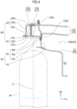
- Figure 4 is a schematic sectional view in an A-A sectional position shown in Figure 1 .
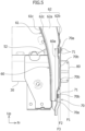
- Figure 5 is a partially enlarged side view of the vehicle structure 100.
- the vehicle structure 100 in this embodiment includes a longitudinal member 50, an extension frame 60, and a shield wall member 70 in addition to the elements described above.
- the longitudinal member 50 is a panel material covering the front end of the floor side member 30 from the front and extending in the vehicle up-down direction.
- the longitudinal member 50 includes a front wall 51 facing the vehicle front and a flange wall 52 extending to the vehicle rear from a vehicle width direction outer side portion of the front wall 51 and joined to a sidewall in the vehicle width direction of the floor side member 30.
- the longitudinal member 50 projects upward with respect to the upper end of the floor side member 30 and projects downward with respect to the lower end of the floor side member 30.
- the front wall 51 of the longitudinal member 50 is in contact with the front end of the floor side member 30.
- the flange wall 52 (see Figure 2 ) on the left side of the longitudinal member 50 is joined to the outer surface of a left side wall portion of the floor side member 30.
- a flange wall (in Figure 2 , hidden behind a shield wall extension part 90) on the right side of the longitudinal member 50 is joined to the outer surface of a right side wall portion of the floor side member 30.
- the dash side frame 40 described above extends from a lower side front portion of the dash side panel 11 to the vehicle front.
- the dash side frame 40 in this example is inclined such that the front end of the dash side frame 40 is slightly further located in the vehicle downward direction than the rear end of the dash side frame 40 in the vehicle front-rear direction.
- the dash side frame 40 includes a dash side member 41 and a dash cross side panel 42, which are joined to each other.
- the dash side member 41 is a member extending to the vehicle front from the dash side panel 11 and located further on the outer side than the floor side member 30 in the vehicle width direction.
- the dash side member 41 projects to the vehicle front along the inclined second side panel part 11b and the inclined third side panel part 11c, for example, in a lower portion of the dash side panel 11.
- Detailed structures such as a sectional shape of the dash side member 41 are described in detail below.
- the dash cross side panel 42 is a panel material joined to a vehicle width direction outer side portion of the dash cross member 12 as shown in Figure 3 .
- a cross member upper flange part 12b 1 extending in the vehicle upward direction
- a cross member lower flange part 12b2 extending in the vehicle downward direction are provided.
- the dash cross side panel 42 covers a vehicle width direction outer side portion opening of the dash cross member 12 (the cross member outer side part 12b) by being joined to the cross member upper flange part 12b 1 and the cross member lower flange part 12b2 by spot welding or the like.
- the extension frame 60 is a member extending forwardly downward from the dash side frame 40 to a position separated to the vehicle width direction outer side with respect to the longitudinal member 50. That is, the lower end portion of the extension frame 60 is located in a position adjusted to a front-rear position of the longitudinal member 50 in the vehicle front-rear direction.
- the extension frame 60 curves in the vehicle downward direction toward the vehicle front and extends in an arcuate shape. Detailed structure such as a cross sectional shape of the extension frame 60 is described in detail below.
- the shield wall member 70 is a panel material having a front surface extending from the extension frame 60 to the longitudinal member 50 and facing the vehicle front, the panel material being joined to the extension frame 60 and the longitudinal member 50.
- the shield wall member 70 has an area larger than an area in a plan view of the front end of the floor side member 30 and a shock absorbing member 80 described below viewed from the vehicle front.
- the shield wall member 70 extends in the vehicle width direction and the vehicle up-down direction and is formed in a generally square panel material.
- the shield wall member 70 closes a gap between an extension frame front part 60a, which is a front part extending in the vehicle downward direction of the extension frame 60 and is located on the vehicle width direction outer side with respect to the longitudinal member 50, and a generally lower half portion of the longitudinal member 50.
- a vehicle width direction outer side portion of the shield wall member 70 is joined, by bolts 71, to the front surface of the extension frame front part 60a of the extension frame 60.
- a vehicle width direction inner side portion of the shield wall member 70 is joined, by the bolts 71, to the front surface of a lower half portion of the front wall 51 of the longitudinal member 50.
- the shield wall member 70 may be joined by welding such as spot welding in addition to the bolt joining or may be joined by welding instead of the bolt joining.
- the shield wall member 70 has a front surface having a large area facing the vehicle front and opposed to the rear surface of the front bumper.
- a shield wall flange part 70a in which bolt insertion holes are opened, is formed at each of approximately four corners of the shield wall member 70.
- the remaining portion other than the shield wall flange part 70a in the shield wall member 70 bulges to project to the vehicle front with respect to the shield wall flange part 70a as a whole.
- a plurality of (in this example, three) beads 70b separated from one another are formed in the portion swelled to the vehicle front in the shield wall member 70.
- the beads 70b extend in the vehicle width direction while having, for example, a sectional shape projecting to bulge to the vehicle front.
- the extension frame 60 is joined to an outer side portion in the vehicle width direction of the dash side frame 40 (in other words, the dash side member 41) and extends forwardly downward from the outer side portion to a position separate to the vehicle width direction outer side with respect to the longitudinal member 50.
- the extension frame 60 is offset to the outer side with respect to the dash side frame 40 in the vehicle width direction.
- the front end of the extension frame 60 is located further in the vehicle downward direction than the rear end of the extension frame 60 in the vehicle front-rear direction.
- a front side portion of the dash side frame 40 forms a first closed sectional structure C1 in a sectional view orthogonal to the extending direction of the dash side frame 40.
- the front side portion of the dash side member 41 is joined to a vehicle width direction outer side surface of the dash cross side panel 42 and forms a first closed sectional structure C1 in cooperation with the dash cross side panel 42.
- the dash side member 41 extends in the vehicle front-rear direction while having a hat-like cross section opened to the vehicle width direction inner side in a sectional view orthogonal to the extending direction of the dash side member 41 (the vehicle front-rear direction, the longitudinal direction).
- the dash side member 41 includes a side member main body part 41a, a side member upper flange part 41b, and a side member lower flange part 41c.
- the side member main body part 41a extends in the vehicle front-rear direction while having a concave cross section opened to the vehicle width direction inner side in the sectional view orthogonal to the extending direction.
- the side member upper flange part 41b projects in the vehicle upward direction from the vehicle width direction inner end of an upper side wall of the side member main body part 41a.
- the side member lower flange part 41c projects in the vehicle downward direction from the vehicle width direction inner end of a lower side wall of the side member main body part 41a.
- the front side portion of the dash side member 41 projects to the vehicle front with respect to the dash side panel 11.
- a side portion opening of a front side portion of the dash side panel 11 is covered by the side member upper flange part 41b and the side member lower flange part 41c being joined to the dash cross side panel 42 by spot welding or the like. Consequently, the front side portion of the dash side member 41 cooperates with the dash cross side panel 42 to form a substantially square (in other words, generally square cylinder) first closed sectional structure C1 in a sectional view of the dash side frame 40 orthogonal to the longitudinal direction.
- the dash cross side panel 42 is held between the cross member upper flange part 12b1 and the cross member lower flange part 12b2 of the cross member outer side part 12b and the side member upper flange part 41b and the side member lower flange part 41c of the dash side member 41.
- the cross member upper flange part 12b1, the dash cross side panel 42, and the side member upper flange part 41b are joined in three layers.
- the cross member lower flange part 12b2, the dash cross side panel 42, and the side member lower flange part 41c are joined in three layers.
- a vehicle width direction position of the dash cross side panel 42 is adjusted to a vehicle width direction position of the third side panel part 11c of the dash side panel 11.
- the dash cross side panel 42 is disposed in the vehicle front of the third side panel part 11c.
- the vehicle width direction outer side portion of the dash cross member 12 extends to the vehicle width direction position of the third side panel part 11c of the dash side panel 11 in the vehicle width direction.
- the lower end of the dash cross side panel 42 is joined to the upper surface of the wheelhouse 20.
- the extension frame 60 includes an inner side extension member 61 and an outer side extension member 62, which are joined to each other.
- the inner side extension member 61 is a member joined to an outer side surface of the vehicle width direction outer side of the dash side member 41.
- the outer side extension member 62 is joined to the inner side extension member 61 and forms a second closed sectional structure C2 in cooperation with the inner side extension member 61.
- the inner side extension member 61 is joined to the outer side extension member 62 from the vehicle downward direction.
- Each of the inner side extension member 61 and the outer side extension member 62 bends in the vehicle downward direction toward the vehicle front above the wheelhouse 20 and extends in an arcuate shape.
- the inner side extension member 61 includes, for example, an inner side longitudinal member 61a, an inner side upper flange part 61b, and an inner side lower flange part 61c and extends while having a Z-shaped cross section.
- the inner side longitudinal member 61a extends in the vehicle up-down direction.
- a rear side portion of the inner side longitudinal member 61a is joined to an outer side surface facing the vehicle width direction outer side of the side member main body part 41a.
- the inner side upper flange part 61b projects to the vehicle width direction inner side from the upper end of the inner side longitudinal member 61a.
- a rear side portion of the inner side upper flange part 61b is joined to the upper surface of the side member main body part 41a.
- the inner side lower flange part 61c projects to the vehicle width direction outer side from the lower end of the inner side longitudinal member 61a.
- the outer side extension member 62 includes an outer side longitudinal member 62a, an outer side upper flange part 62b, and an outer side lower flange part 62c and extends while having a Z-shaped cross section.
- the outer side longitudinal member 62a extends in the vehicle up-down direction and is separated to the vehicle width direction outer side with respect to the inner side longitudinal member 61a.
- the outer side upper flange part 62b projects to the vehicle width direction inner side from the upper end of the outer side longitudinal member 62a.
- the vehicle width direction inner end of the outer side upper flange part 62b is joined to the inner side upper flange part 61b.
- the outer side lower flange part 62c projects to the vehicle width direction outer side from the lower end of the outer side longitudinal member 62a and is joined to the inner side lower flange part 61c. Consequently, the outer side extension member 62 cooperates with the inner side extension member 61 to form a substantially square (in other words, a generally square cylinder) second closed sectional structure C2 in a sectional view orthogonal to the extending direction of the extension frame 60.
- a part of the first closed sectional structure C1, a part of the second closed sectional structure C2, and the dash cross member 12 line up adjacently in the vehicle width direction.
- the vehicle width direction outer side end of the cross member outer side part 12b, an inner side joining part C1a overlapping the vehicle width direction outer side end of the cross member outer side part 12b in the first closed sectional structure C1, and an outer side joining part C2a overlapping the inner side joining part C1a in the second closed sectional structure C2 overlap laterally side by side in the vehicle width direction.
- the dash side frame 40 (the dash side member 41) and the inner side joining part C1a of the first closed sectional structure C1 are located in a region crossing an imaginary plane X passing the center of the tire width direction of the front wheel W (in other words, right above the largest outer diameter portion of the front wheel W) above the front wheel W.
- the extension frame 60 is located on the vehicle width direction outer side with respect to the imaginary plane X.
- the outer diameter of the front wheel W is smaller toward the tire width direction outer side. Therefore, a gap between the front wheel W and the dash side frame 40 is narrower than a gap between the front wheel W and the extension frame 60.
- the vehicle is shown in a suspended state and the vehicle including the front wheel W is floating in the air.
- the gap between the front wheel W and the dash side frame 40 is actually narrower than the gap shown in Figure 4 . Therefore, if the extension frame 60 is directly extended forwardly downward from the front end of the dash side frame 40, in some cases, the extension frame 60 interferes with the front wheel W, making it difficult to dispose the extension frame 60.
- the extension frame 60 is disposed so as not to interfere with the front wheel W, in a position offset to the vehicle width direction outer side with respect to the dash side frame 40 located right above the maximum outer diameter portion of the front wheel W.
- the vehicle structure 100 in this embodiment further includes a shock absorbing member 80, a shield wall extension part 90, and a wheelhouse reinforcement 24.
- the shock absorbing member 80 is a member joined to the front wall 51 of the longitudinal member 50 and projecting forward.
- the shock absorbing member 80 is disposed to cover the front end of the floor side member 30 in a plan view viewed from the vehicle front.
- the shock absorbing member 80 is formed by a panel material.
- the front bumper not shown, extends in the vehicle width direction in the front of the shock absorbing member 80.
- the shock absorbing member 80 is opposed to the rear surface of the front bumper and supports the front bumper from the rear. A collision load in a front collision or the like is input to the shock absorbing member 80 via the front bumper.
- a front end F1 of the shock absorbing member 80 is located in the vehicle front with respect to a front end F2 of the shield wall member 70 and a front end F3 of the extension frame 60 is located in the vehicle rear with respect to the front end F2 of the shield wall member 70.
- the front surface, which is the front end F1 of the shock absorbing member 80 is located in the vehicle front with respect to the tops of the beads 70b, which are the front end F2 of the shield wall member 70, and the front surface of the extension frame front part 60a, which is the front end F3 of the extension frame 60, is located in the vehicle rear with respect to the tops of the beads 70b of the shield wall member 70.
- the extension frame front part 60a extends in the vehicle up-down direction and supports a vehicle width direction outer side portion of the shield wall member 70 from the rear.
- the extension frame front part 60a is a portion in which a front portion extending in the vehicle downward direction of the outer side upper flange part 62b of the outer side extension member 62 and a front portion extending in the vehicle downward direction of the inner side upper flange part 61b of the inner side extension member 61 overlap.
- the shield wall extension part 90 is a panel material joined to an upper portion of the shield wall member 70 and extending in the vehicle upward direction from the upper portion.
- the shield wall extension part 90 extends from the extension frame 60 to the longitudinal member 50 to close a gap between a bending portion above the extension frame front part 60a of the extension frame 60 and a portion of a generally upper half of the longitudinal member 50.
- a vehicle width direction inner side portion of the shield wall extension part 90 is joined to the front wall 51 of the longitudinal member 50.
- a vehicle width direction outer side portion of the shield wall extension part 90 is curved in a shape adjusted to a curving shape of the extension frame 60 and is joined to the outer side upper flange part 62b of the outer side extension member 62 of the extension frame 60.
- the wheelhouse extension panel 23 includes an extension panel flange part 23a joined to a shield wall extension flange part 90a formed in an upper portion of the shield wall extension part 90 and supports the shield wall extension part 90 from the rear.
- the wheelhouse reinforcement 24 is a panel material extending from the upper surface of a front portion of the wheelhouse extension panel 23 to the upper portion of the shield wall extension part 90 and joined to the wheelhouse extension panel 23 and the shield wall extension part 90.
- the wheelhouse reinforcement 24 includes a lower flange part 24a joined to the upper surface of the wheelhouse extension panel 23 and an upper flange part 24b joined to the shield wall extension flange part 90a and supports the shield wall extension part 90 from the rear in conjunction with the wheelhouse extension panel 23.
- the dash side frame 40 extends to the vehicle front from the dash side panel 11 and is located further on the outer side than the floor side member 30 in the vehicle width direction
- the longitudinal member 50 covers the front end of the floor side member 30 from the front and extends in the vehicle up-down direction
- the extension frame 60 extends forwardly downward from the dash side frame 40 to the position separated to the vehicle width direction outer side with respect to the longitudinal member 50
- the shield wall member 70 has the front surface extending from the extension frame 60 to the longitudinal member 50 and facing the vehicle front and is joined to the extension frame 60 and the longitudinal member 50.
- a plane having a large area facing the vehicle front is easily formed by the front surface of the shield wall member 70 between the longitudinal member 50 covering the front end of the floor side member 30 having high strength and the extension frame 60 extending forwardly downward from the dash side frame 40.
- the shield wall member 70 In a collision such as a front collision in which obstacles in front of the vehicle collide with the vehicle front portion, the obstacles are crushed in a wide range by the shield wall member 70. Therefore, a some of the collision energy due to a collision load is effectively absorbed as deformation energy of the obstacles. A collision load input to the vehicle body can be effectively reduced.
- the vehicle width direction outer side portion of the shield wall member 70 is supported from the rear by the extension frame 60 extending to extend from the dash side frame 40.
- the shield wall member 70 does not immediately retract, and deformation to the vehicle rear of the vehicle width direction outer side portion of the shield wall member 70 is reduced. That is, it is possible to easily impart, to the shield wall member 70, moderate strength that can crush obstacles in a wide range.
- the vehicle structure 100 in this embodiment is a structure that can effectively reduce, in a collision such as a front collision, collision energy input to the vehicle body.
- the extension frame 60 is joined to an outer side portion in the vehicle width direction of the dash side frame 40 and extends from the outer side portion. Consequently, the extension frame 60 does not interfere with the front wheel W and can be easily extended forwardly downward from the dash side frame 40 to a position separated to the vehicle width direction outer side with respect to the longitudinal member 50.
- a part of the first closed sectional structure C1 of the front side portion of the dash side frame 40, a part of the second closed sectional structure C2 of the extension frame 60, and the dash cross member 12 line up adjacently in the vehicle width direction. Consequently, a part including a joining portion of the extension frame 60 and the dash side frame 40 is formed at extremely high strength. Rigidity against a collision load that can be input because of offset collision or the like can be effectively improved.
- the front end F1 of the shock absorbing member 80 is located in the vehicle front with respect to the front end F2 of the shield wall member 70 and the front end F3 of the extension frame 60 is located in the vehicle rear with respect to the front end F2 of the shield wall member 70. Consequently, the shock absorbing member 80 among the shock absorbing member 80, the shield wall member 70, and the extension frame 60 is deformed by a collision load due to front collision or the like earliest to absorb some of the collision energy. After the deformation of the shock absorbing member 80, the shield wall member 70 crushes obstacles, whereby an input load to the vehicle body decreases. Thereafter, the shield wall member 70 is deformed to absorb some of the collision energy. As a result, collision energy input to the extension frame 60 more susceptible to a collision load from the front compared with the shield wall member 70 can be reduced.
- the shield wall extension part 90 is joined to the upper portion of the shield wall member 70 and extends in the vehicle upward direction from the upper portion and the wheelhouse reinforcement 24 extends from the upper surface of the wheelhouse extension panel 23 to the upper portion of the shield wall extension part 90 and is joined to the wheelhouse extension panel 23 and the shield wall extension part. Consequently, some of the collision energy that can be input to the shield wall member 70 because of front collision or the like is effectively transmitted to the wheelhouse reinforcement 24 and the wheelhouse reinforcement 24 is deformed, whereby the collision energy is effectively absorbed. That is, the vehicle structure 100 in which collision energy that can be input from the front because of a front collision or the like is more effectively easily absorbed is constructed.
- the inner side extension member 61 having the Z-shaped cross section and the outer side extension member 62 having the Z-shaped cross section are joined to each other, whereby the second closed sectional structure C2 of the extension frame 60 is formed. Consequently, even if the extension frame 60 is curved longer and larger compared with the dash side frame 40, moldability of the extension frame 60 is not deteriorated and the extension frame 60 having high rigidity can be easily formed.
- the sectional area of the extension frame 60 can also be easily changed according to necessity. It is easy to control a deformation mode of the extension frame 60 in a front collision or the like.
Landscapes
- Engineering & Computer Science (AREA)
- Chemical & Material Sciences (AREA)
- Combustion & Propulsion (AREA)
- Transportation (AREA)
- Mechanical Engineering (AREA)
- Body Structure For Vehicles (AREA)
Abstract
[Problem to be Solved] To effectively reduce collision energy input to a vehicle body.
[Solution] There is provided a vehicle structure 100 including a dash panel 10 and a floor side member 30. The vehicle structure 100 includes a dash side panel 11 extending in the vehicle front-rear direction from a vehicle width direction outer side portion of the dash panel 10, a dash side frame 40 extending to a vehicle front from the dash side panel 11 and located further on the outer side than the floor side member 30 in the vehicle width direction, a longitudinal member 50 covering the front end of the floor side member 30 from the front and extending in the vehicle up-down direction, an extension frame 60 extending forwardly downward from the dash side frame 40 to a position separated to the vehicle width direction outer side with respect to the longitudinal member 50, and a shield wall member 70 having a front surface extending from the extension frame 60 to the longitudinal member 50 and facing the vehicle front, the shield wall member 70 being joined to the extension frame 60 and the longitudinal member 50.
Description
- The present invention relates to a vehicle structure including a dash panel and floor side members.
- In vehicle width direction outer side portions of the lower surface of a floor panel of a vehicle, floor side members extending in the vehicle front-rear direction and constituting a part of a vehicle body frame are disposed. The floor side members extend in the vehicle front-rear direction and have particularly high strength against an input load in the axial direction of the floor side members.
- As an example of the vehicle structure including the floor side members described above, a structure disclosed in Patent Literature 1 is known. In the structure in this example, a first front side member is provided, in the vehicle front of side members functioning as the floor side members, coaxially with the side members and projects forward, and furthermore, a second front side member projects to the vehicle front on the vehicle width direction outer side of the first front side member. With this configuration, even in a vehicle having a short crush stroke of a vehicle front portion, the front side members of the vehicle front portion are each compressed and deformed in the axial direction to be able to absorb, with a short stroke, collision energy due to front collision or the like.
- [Patent Literature 1]
JP 2005-001406 A - However, in the structure disclosed in Patent Literature 1, in a collision such as offset collision in which obstacles in front of the vehicle collide with the vehicle front portion, parts of the obstacles are crushed at the front ends of small areas of the front side members projecting to the vehicle front and, thereafter, the remaining portions of the obstacles directly enter the vehicle body. Therefore, in the collision such as the offset collision, it is likely that collision energy can be input to the vehicle body while energy absorption remains insufficient, and there is room of improvement.
- Therefore, an object of the present invention is to provide a vehicle structure that can effectively reduce collision energy input to a vehicle body in collision such as front collision.
- In order to achieve the object described above, according to an aspect of the present invention, there is provided a vehicle structure including: a dash panel provided in a vehicle front portion; and a floor side member provided in a vehicle width direction outer side portion of a lower surface of a floor panel of a vehicle and extending in a vehicle front-rear direction. The vehicle structure includes: a dash side panel extending in the vehicle front-rear direction from a vehicle width direction outer side portion of the dash panel; a dash side frame extending to a vehicle front from the dash side panel and located further on an outer side than the floor side member in a vehicle width direction; a longitudinal member covering a front end of the floor side member from a front and extending in a vehicle up-down direction; an extension frame extending forwardly downward from the dash side frame to a position separated to a vehicle width direction outer side with respect to the longitudinal member; and a shield wall member having a front surface extending from the extension frame to the longitudinal member and facing the vehicle front, the shield wall member being joined to the extension frame and the longitudinal member.
- According to the present invention, it is possible to provide a vehicle structure that can effectively reduce collision energy input to a vehicle body in a collision such as a front collision.
-
- [
Figure 1] Figure 1 is a perspective view of a vehicle structure according to an embodiment of the present invention. - [
Figure 2] Figure 2 is a perspective view of the vehicle structure viewed from another angle. - [
Figure 3] Figure 3 is a main part enlarged view of a cut model of the vehicle structure. - [
Figure 4] Figure 4 is a schematic sectional view in an A-A sectional position shown inFigure 1 . - [
Figure 5] Figure 5 is a partially enlarged side view of the vehicle structure. - An embodiment of the present invention is described below with reference to the accompanying drawings.
Figure 1 andFigure 2 are diagrams for describing avehicle structure 100 according to the embodiment of the present invention.Figure 1 is a perspective view viewed from the vehicle front.Figure 2 is a perspective view viewed from the vehicle front at another angle. Note that, in the figures, an arrow Fr direction indicates the front in the vehicle front-rear direction and an arrow U direction indicates the vehicle upward direction in the vehicle up-down direction. "A front portion (a front end) and a rear portion (a rear end)" in the description of the embodiment correspond to a front portion and a rear portion in the vehicle front-rear direction. Arrows L and R directions indicate the left side and the right side in the vehicle width direction. "Left and right" in the description of this embodiment correspond to the left and the right at the time when an occupant in a vehicle interior faces the vehicle front. - As shown in
Figure 1 andFigure 2 , thevehicle structure 100 in this embodiment is mainly applied to a vehicle front portion and a vehicle bottom portion. Although not particularly limited, in this embodiment, a vehicle to which thevehicle structure 100 is applied is a small vehicle having a relatively short dimension in the vehicle front-rear direction of the vehicle front portion (specifically, a portion from adash panel 10 described below to a front bumper, not shown). Note that, in the figures, a portion including a right front wheel of the vehicle in thevehicle structure 100 is shown. A portion including a left front wheel of thevehicle structure 100 is the same structure as the portion including the right front wheel except that the portion including the left front wheel is symmetrical with respect to the portion including the right front wheel. Illustration of the portion including the left front wheel is omitted. - In this embodiment, the vehicle to which the
vehicle structure 100 is applied is an electric vehicle. For example, a battery, not shown, and as electric motor, not shown, for vehicle traveling are mounted on the vehicle. The electric motor operates with electric power supplied from the battery. When an electric vehicle and an engine driven vehicle are compared, the electric vehicle is generally heavier than the engine driven vehicle if vehicle sizes are the same. - Referring to
Figure 1 andFigure 2 , thevehicle structure 100 in this embodiment includes adash panel 10, adash side panel 11, adash cross member 12, awheelhouse 20, afloor side member 30, and adash side frame 40. - The
dash panel 10 is provided in a vehicle front portion. Thedash panel 10 is, for example, a panel material partitioning a front unit compartment R1 and an occupant compartment and generally extends in the vehicle width direction and the vehicle up-down direction. In the front unit compartment R1, driving devices such as an engine and an electric motor (in this embodiment, the electric motor) and the like are disposed. An upper portion of a portion including a vehicle width direction outer side portion of thedash panel 10 constitutes a retractingpart 10a bent to retract to the vehicle rear. - The front unit compartment R1 is called a power unit compartment as well and is formed mainly by the
dash panel 10, a front bumper extending in the vehicle width direction at the not-shown vehicle front end and a not-shown front hood extending from the upper end portion of thedash panel 10 to the upper end portion of the front bumper. - The
dash side panel 11 is provided in the vehicle width direction outer side portion of thedash panel 10 and located above a front wheel W. Thedash side panel 11 is a panel material joined to an upper side portion of the vehicle width direction outer side portion of thedash panel 10 and extends in the vehicle front-rear direction from the vehicle width direction outer side portion of thedash panel 10. - The
dash side panel 11 includes a first side panel part 1 1a joined to the vehicle width direction outer side portion of thedash panel 10 and facing the vehicle width direction outer side, a secondside panel part 11b generally projecting to the vehicle width direction inner side from the front end of the firstside panel part 11a and facing the vehicle front side, and a thirdside panel part 11c projecting to the vehicle front from the vehicle width direction inner end of the secondside panel part 11b and facing the vehicle width direction outer side. The secondside panel part 11b is inclined such that the inner end of the secondside panel part 11b is located further in the vehicle front than the outer end of the secondside panel part 11b in the vehicle width direction. The secondside panel part 11b and the thirdside panel part 11c are located further in the vehicle front than the retractingpart 10a of thedash panel 10. - The
dash cross member 12 is joined to the intermediate portion in the vehicle up-down direction on the front surface of thedash panel 10. Thedash cross member 12 includes a cross membermain body part 12a and a cross memberouter side part 12b. The cross membermain body part 12a has a hat-like cross section and extends in the vehicle width direction along the front surface of thedash panel 10. The cross memberouter side part 12b is formed integrally with the cross membermain body part 12a and continues from a vehicle width direction outer side portion of the cross membermain body part 12a and extends to the vicinity of the vehicle width direction outer side portion of thedash panel 10. The cross memberouter side part 12b is generally formed in an L shape in plan view viewed from the vehicle up-down direction and formed to extend along the retractingpart 10a of thedash panel 10. A vehicle width direction outer side portion of the cross memberouter side part 12b is opened to the vehicle width direction outer side. - The
wheelhouse 20 is a panel material covering the front wheel W of the vehicle from above and is joined to a lower side portion in the vehicle width direction outer side portion of thedash panel 10. In this embodiment, thewheelhouse 20 includes a wheelhousemain body panel 21, astrut tower 22, and awheelhouse extension panel 23. - The wheelhouse
main body panel 21 constitutes a most portion of thewheelhouse 20 and is formed to expand toward the vehicle width direction inner side and the vehicle upward direction in a shape generally adjusted to the outer shape of the front wheel W. - The
strut tower 22 is a structure including a panel material for attaching an upper portion of a strut (not shown) extending in the vehicle up-down direction of a strut-type front suspension device (not shown). Thestrut tower 22 is formed integrally with the wheelhousemain body panel 21. - In this embodiment, the
strut tower 22 is disposed in the rear with respect to thedash panel 10. That is, the vehicle to which thevehicle structure 100 in this embodiment is applied is a vehicle in which thestrut tower 22 is located behind thedash panel 10 and the distance between thedash panel 10 and the vehicle front end (the front bumper) is markedly short. Therefore, among small vehicles, the vehicle is a small vehicle in which a dimension in the front-rear direction of a vehicle front portion is markedly short and a space in the front-rear direction of the front unit compartment R1 is narrow. In the vehicle, in relation with the axle of the front wheel W, for example, thedash panel 10 is located in the front with respect to the axle of the front wheel W in the vehicle front-rear direction and is disposed in a front-rear position between the axle of the front wheel W and thestrut tower 22. - The
wheelhouse extension panel 23 is a panel material extending the wheelhousemain body panel 21 forward and is joined to a front portion of the wheelhousemain body panel 21 and extends forward from the front portion. That is, thewheelhouse extension panel 23 is located in the front with respect to thedash panel 10 and covers an upward direction further in a front side portion than the axle of the front wheel W. - A lower portion of the vehicle width direction outer side portion of the
dash panel 10 is joined to a portion between thestrut tower 22 and thewheelhouse extension panel 23 on the upper surface of the wheelhouse 20. - The
floor side member 30 is a member having high rigidity constituting a part of a vehicle body frame in the bottom portion of the vehicle body. Thefloor side member 30 is provided in a vehicle width direction outer side portion of the lower surface of afloor panel 31 of the vehicle and extends in the vehicle front-rear direction. In other words, thefloor side member 30 is disposed below thedash panel 10 and extends in the vehicle front-rear direction. - Referring to
Figure 1 andFigure 2 , thefloor side member 30 extends from a position further in the front than thedash panel 10 to a position further in the rear than thedash panel 10 in the vehicle front-rear direction. Therefore, thefloor side member 30 extends to cross thedash panel 10 in a plan view viewed from the vehicle up-down direction. A front portion of thefloor side member 30 projects forward with respect to thedash panel 10 in a plan view viewed from the vehicle up-down direction. - The
floor side member 30 has a concave cross section opened in the vehicle upward direction and extends in the vehicle front-rear direction in a sectional view orthogonal to an extending direction of the floor side member 30 (the vehicle front-rear direction, the longitudinal direction). A frontupper cover 32 and afloor panel 31 are joined to an upper portion of thefloor side member 30. An upper opening of thefloor side member 30 is closed by the frontupper cover 32 and the floor panel being joined to the upper portion of thefloor side member 30 by spot welding or the like. Consequently, a substantially square (in other words, a substantially square cylinder) closed sectional structure is configured in a sectional view of thefloor side member 30 orthogonal to the longitudinal direction. - The
floor side member 30 is provided in each of a right side portion and a left side portion in the vehicle width direction on the lower surface of thefloor panel 31. Thefloor side member 30 extends over the generally entire front-rear direction of the vehicle in the vehicle-front-rear direction. - The
dash side frame 40 extends to the vehicle front from thedash side panel 11 and is located further on the outer side than thefloor side member 30 in the vehicle width direction in a plan view viewed from the vehicle up-down direction. Thedash side frame 40 is disposed above a vehicle width direction outer side portion of the wheelhouse 20. Specifically, thedash side frame 40 extends to the vehicle front from a front portion of thedash side panel 11 joined to the vehicle width direction outer side portion of thedash panel 10. - Here, in a collision, such as a front collision, in which obstacles in the front of the vehicle collide with the vehicle front portion or offset collision, if parts of the obstacles are crushed at the front ends of small areas of the
floor side members 30 projecting to the vehicle front, the remaining portions of the obstacles directly enter the vehicle body. In such a form, in a collision such as a front collision, it is likely that collision energy will be input to the vehicle body while energy absorption remains insufficient. In contrast, thevehicle structure 100 according to this embodiment has the following structure. - Next, a main part of the
vehicle structure 100 is described in detail with reference toFigure 1 to Figure 5 .Figure 3 is a main part enlarged view of a cut model of thevehicle structure 100.Figure 4 is a schematic sectional view in an A-A sectional position shown inFigure 1 .Figure 5 is a partially enlarged side view of thevehicle structure 100. - The
vehicle structure 100 in this embodiment includes alongitudinal member 50, anextension frame 60, and ashield wall member 70 in addition to the elements described above. - Referring to
Figure 1 andFigure 2 , thelongitudinal member 50 is a panel material covering the front end of thefloor side member 30 from the front and extending in the vehicle up-down direction. Thelongitudinal member 50 includes afront wall 51 facing the vehicle front and aflange wall 52 extending to the vehicle rear from a vehicle width direction outer side portion of thefront wall 51 and joined to a sidewall in the vehicle width direction of thefloor side member 30. - The
longitudinal member 50 projects upward with respect to the upper end of thefloor side member 30 and projects downward with respect to the lower end of thefloor side member 30. Thefront wall 51 of thelongitudinal member 50 is in contact with the front end of thefloor side member 30. The flange wall 52 (seeFigure 2 ) on the left side of thelongitudinal member 50 is joined to the outer surface of a left side wall portion of thefloor side member 30. A flange wall (inFigure 2 , hidden behind a shield wall extension part 90) on the right side of thelongitudinal member 50 is joined to the outer surface of a right side wall portion of thefloor side member 30. - Referring to
Figure 1 andFigure 3 , thedash side frame 40 described above extends from a lower side front portion of thedash side panel 11 to the vehicle front. Thedash side frame 40 in this example is inclined such that the front end of thedash side frame 40 is slightly further located in the vehicle downward direction than the rear end of thedash side frame 40 in the vehicle front-rear direction. Thedash side frame 40 includes adash side member 41 and a dashcross side panel 42, which are joined to each other. - The
dash side member 41 is a member extending to the vehicle front from thedash side panel 11 and located further on the outer side than thefloor side member 30 in the vehicle width direction. Thedash side member 41 projects to the vehicle front along the inclined secondside panel part 11b and the inclined thirdside panel part 11c, for example, in a lower portion of thedash side panel 11. Detailed structures such as a sectional shape of thedash side member 41 are described in detail below. - The dash
cross side panel 42 is a panel material joined to a vehicle width direction outer side portion of thedash cross member 12 as shown inFigure 3 . At the vehicle width direction outer side end of the cross memberouter side part 12b, a cross memberupper flange part 12b 1 extending in the vehicle upward direction and a cross member lower flange part 12b2 extending in the vehicle downward direction are provided. The dashcross side panel 42 covers a vehicle width direction outer side portion opening of the dash cross member 12 (the cross memberouter side part 12b) by being joined to the cross memberupper flange part 12b 1 and the cross member lower flange part 12b2 by spot welding or the like. - The
extension frame 60 is a member extending forwardly downward from thedash side frame 40 to a position separated to the vehicle width direction outer side with respect to thelongitudinal member 50. That is, the lower end portion of theextension frame 60 is located in a position adjusted to a front-rear position of thelongitudinal member 50 in the vehicle front-rear direction. Theextension frame 60 curves in the vehicle downward direction toward the vehicle front and extends in an arcuate shape. Detailed structure such as a cross sectional shape of theextension frame 60 is described in detail below. - The
shield wall member 70 is a panel material having a front surface extending from theextension frame 60 to thelongitudinal member 50 and facing the vehicle front, the panel material being joined to theextension frame 60 and thelongitudinal member 50. Theshield wall member 70 has an area larger than an area in a plan view of the front end of thefloor side member 30 and ashock absorbing member 80 described below viewed from the vehicle front. In this example, theshield wall member 70 extends in the vehicle width direction and the vehicle up-down direction and is formed in a generally square panel material. Theshield wall member 70 closes a gap between an extension framefront part 60a, which is a front part extending in the vehicle downward direction of theextension frame 60 and is located on the vehicle width direction outer side with respect to thelongitudinal member 50, and a generally lower half portion of thelongitudinal member 50. A vehicle width direction outer side portion of theshield wall member 70 is joined, bybolts 71, to the front surface of the extension framefront part 60a of theextension frame 60. A vehicle width direction inner side portion of theshield wall member 70 is joined, by thebolts 71, to the front surface of a lower half portion of thefront wall 51 of thelongitudinal member 50. Note that theshield wall member 70 may be joined by welding such as spot welding in addition to the bolt joining or may be joined by welding instead of the bolt joining. - The
shield wall member 70 has a front surface having a large area facing the vehicle front and opposed to the rear surface of the front bumper. A shieldwall flange part 70a, in which bolt insertion holes are opened, is formed at each of approximately four corners of theshield wall member 70. The remaining portion other than the shieldwall flange part 70a in theshield wall member 70 bulges to project to the vehicle front with respect to the shieldwall flange part 70a as a whole. A plurality of (in this example, three)beads 70b separated from one another are formed in the portion swelled to the vehicle front in theshield wall member 70. Thebeads 70b extend in the vehicle width direction while having, for example, a sectional shape projecting to bulge to the vehicle front. - In this embodiment, the
extension frame 60 is joined to an outer side portion in the vehicle width direction of the dash side frame 40 (in other words, the dash side member 41) and extends forwardly downward from the outer side portion to a position separate to the vehicle width direction outer side with respect to thelongitudinal member 50. In other words, theextension frame 60 is offset to the outer side with respect to thedash side frame 40 in the vehicle width direction. The front end of theextension frame 60 is located further in the vehicle downward direction than the rear end of theextension frame 60 in the vehicle front-rear direction. - In this embodiment, a front side portion of the
dash side frame 40 forms a first closed sectional structure C1 in a sectional view orthogonal to the extending direction of thedash side frame 40. - Specifically, the front side portion of the
dash side member 41 is joined to a vehicle width direction outer side surface of the dashcross side panel 42 and forms a first closed sectional structure C1 in cooperation with the dashcross side panel 42. Thedash side member 41 extends in the vehicle front-rear direction while having a hat-like cross section opened to the vehicle width direction inner side in a sectional view orthogonal to the extending direction of the dash side member 41 (the vehicle front-rear direction, the longitudinal direction). Thedash side member 41 includes a side membermain body part 41a, a side memberupper flange part 41b, and a side memberlower flange part 41c. The side membermain body part 41a extends in the vehicle front-rear direction while having a concave cross section opened to the vehicle width direction inner side in the sectional view orthogonal to the extending direction. The side memberupper flange part 41b projects in the vehicle upward direction from the vehicle width direction inner end of an upper side wall of the side membermain body part 41a. The side memberlower flange part 41c projects in the vehicle downward direction from the vehicle width direction inner end of a lower side wall of the side membermain body part 41a. - The front side portion of the
dash side member 41 projects to the vehicle front with respect to thedash side panel 11. A side portion opening of a front side portion of thedash side panel 11 is covered by the side memberupper flange part 41b and the side memberlower flange part 41c being joined to the dashcross side panel 42 by spot welding or the like. Consequently, the front side portion of thedash side member 41 cooperates with the dashcross side panel 42 to form a substantially square (in other words, generally square cylinder) first closed sectional structure C1 in a sectional view of thedash side frame 40 orthogonal to the longitudinal direction. - The dash
cross side panel 42 is held between the cross member upper flange part 12b1 and the cross member lower flange part 12b2 of the cross memberouter side part 12b and the side memberupper flange part 41b and the side memberlower flange part 41c of thedash side member 41. The cross member upper flange part 12b1, the dashcross side panel 42, and the side memberupper flange part 41b are joined in three layers. The cross member lower flange part 12b2, the dashcross side panel 42, and the side memberlower flange part 41c are joined in three layers. - A vehicle width direction position of the dash
cross side panel 42 is adjusted to a vehicle width direction position of the thirdside panel part 11c of thedash side panel 11. The dashcross side panel 42 is disposed in the vehicle front of the thirdside panel part 11c. In other words, the vehicle width direction outer side portion of thedash cross member 12 extends to the vehicle width direction position of the thirdside panel part 11c of thedash side panel 11 in the vehicle width direction. As shown inFigure 3 , the lower end of the dashcross side panel 42 is joined to the upper surface of the wheelhouse 20. - In this embodiment, the
extension frame 60 includes an innerside extension member 61 and an outerside extension member 62, which are joined to each other. The innerside extension member 61 is a member joined to an outer side surface of the vehicle width direction outer side of thedash side member 41. The outerside extension member 62 is joined to the innerside extension member 61 and forms a second closed sectional structure C2 in cooperation with the innerside extension member 61. The innerside extension member 61 is joined to the outerside extension member 62 from the vehicle downward direction. Each of the innerside extension member 61 and the outerside extension member 62 bends in the vehicle downward direction toward the vehicle front above the wheelhouse 20 and extends in an arcuate shape. - Specifically, the inner
side extension member 61 includes, for example, an inner sidelongitudinal member 61a, an inner sideupper flange part 61b, and an inner sidelower flange part 61c and extends while having a Z-shaped cross section. The inner sidelongitudinal member 61a extends in the vehicle up-down direction. A rear side portion of the inner sidelongitudinal member 61a is joined to an outer side surface facing the vehicle width direction outer side of the side membermain body part 41a. The inner sideupper flange part 61b projects to the vehicle width direction inner side from the upper end of the inner sidelongitudinal member 61a. A rear side portion of the inner sideupper flange part 61b is joined to the upper surface of the side membermain body part 41a. The inner sidelower flange part 61c projects to the vehicle width direction outer side from the lower end of the inner sidelongitudinal member 61a. - The outer
side extension member 62 includes an outer sidelongitudinal member 62a, an outer sideupper flange part 62b, and an outer sidelower flange part 62c and extends while having a Z-shaped cross section. The outer sidelongitudinal member 62a extends in the vehicle up-down direction and is separated to the vehicle width direction outer side with respect to the inner sidelongitudinal member 61a. The outer sideupper flange part 62b projects to the vehicle width direction inner side from the upper end of the outer sidelongitudinal member 62a. The vehicle width direction inner end of the outer sideupper flange part 62b is joined to the inner sideupper flange part 61b. The outer sidelower flange part 62c projects to the vehicle width direction outer side from the lower end of the outer sidelongitudinal member 62a and is joined to the inner sidelower flange part 61c. Consequently, the outerside extension member 62 cooperates with the innerside extension member 61 to form a substantially square (in other words, a generally square cylinder) second closed sectional structure C2 in a sectional view orthogonal to the extending direction of theextension frame 60. - Referring to
Figure 3 , in this embodiment, a part of the first closed sectional structure C1, a part of the second closed sectional structure C2, and thedash cross member 12 line up adjacently in the vehicle width direction. The vehicle width direction outer side end of the cross memberouter side part 12b, an inner side joining part C1a overlapping the vehicle width direction outer side end of the cross memberouter side part 12b in the first closed sectional structure C1, and an outer side joining part C2a overlapping the inner side joining part C1a in the second closed sectional structure C2 overlap laterally side by side in the vehicle width direction. - Referring to
Figure 4 , in this embodiment, the dash side frame 40 (the dash side member 41) and the inner side joining part C1a of the first closed sectional structure C1 are located in a region crossing an imaginary plane X passing the center of the tire width direction of the front wheel W (in other words, right above the largest outer diameter portion of the front wheel W) above the front wheel W. On the other hand, theextension frame 60 is located on the vehicle width direction outer side with respect to the imaginary plane X. The outer diameter of the front wheel W is smaller toward the tire width direction outer side. Therefore, a gap between the front wheel W and thedash side frame 40 is narrower than a gap between the front wheel W and theextension frame 60. Note that, inFigure 4 , the vehicle is shown in a suspended state and the vehicle including the front wheel W is floating in the air. The gap between the front wheel W and thedash side frame 40 is actually narrower than the gap shown inFigure 4 . Therefore, if theextension frame 60 is directly extended forwardly downward from the front end of thedash side frame 40, in some cases, theextension frame 60 interferes with the front wheel W, making it difficult to dispose theextension frame 60. In this regard, theextension frame 60 is disposed so as not to interfere with the front wheel W, in a position offset to the vehicle width direction outer side with respect to thedash side frame 40 located right above the maximum outer diameter portion of the front wheel W. - The
vehicle structure 100 in this embodiment further includes ashock absorbing member 80, a shieldwall extension part 90, and awheelhouse reinforcement 24. - The
shock absorbing member 80 is a member joined to thefront wall 51 of thelongitudinal member 50 and projecting forward. Theshock absorbing member 80 is disposed to cover the front end of thefloor side member 30 in a plan view viewed from the vehicle front. Theshock absorbing member 80 is formed by a panel material. The front bumper, not shown, extends in the vehicle width direction in the front of theshock absorbing member 80. Theshock absorbing member 80 is opposed to the rear surface of the front bumper and supports the front bumper from the rear. A collision load in a front collision or the like is input to theshock absorbing member 80 via the front bumper. - Referring to
Figure 5 , in this embodiment, a front end F1 of theshock absorbing member 80 is located in the vehicle front with respect to a front end F2 of theshield wall member 70 and a front end F3 of theextension frame 60 is located in the vehicle rear with respect to the front end F2 of theshield wall member 70. Specifically, in this example, in a side view viewed from the vehicle width direction, the front surface, which is the front end F1, of theshock absorbing member 80 is located in the vehicle front with respect to the tops of thebeads 70b, which are the front end F2 of theshield wall member 70, and the front surface of the extension framefront part 60a, which is the front end F3 of theextension frame 60, is located in the vehicle rear with respect to the tops of thebeads 70b of theshield wall member 70. - The extension frame
front part 60a extends in the vehicle up-down direction and supports a vehicle width direction outer side portion of theshield wall member 70 from the rear. The extension framefront part 60a is a portion in which a front portion extending in the vehicle downward direction of the outer sideupper flange part 62b of the outerside extension member 62 and a front portion extending in the vehicle downward direction of the inner sideupper flange part 61b of the innerside extension member 61 overlap. - The shield
wall extension part 90 is a panel material joined to an upper portion of theshield wall member 70 and extending in the vehicle upward direction from the upper portion. The shieldwall extension part 90 extends from theextension frame 60 to thelongitudinal member 50 to close a gap between a bending portion above the extension framefront part 60a of theextension frame 60 and a portion of a generally upper half of thelongitudinal member 50. A vehicle width direction inner side portion of the shieldwall extension part 90 is joined to thefront wall 51 of thelongitudinal member 50. A vehicle width direction outer side portion of the shieldwall extension part 90 is curved in a shape adjusted to a curving shape of theextension frame 60 and is joined to the outer sideupper flange part 62b of the outerside extension member 62 of theextension frame 60. Thewheelhouse extension panel 23 includes an extensionpanel flange part 23a joined to a shield wall extension flangepart 90a formed in an upper portion of the shieldwall extension part 90 and supports the shieldwall extension part 90 from the rear. - The
wheelhouse reinforcement 24 is a panel material extending from the upper surface of a front portion of thewheelhouse extension panel 23 to the upper portion of the shieldwall extension part 90 and joined to thewheelhouse extension panel 23 and the shieldwall extension part 90. Thewheelhouse reinforcement 24 includes alower flange part 24a joined to the upper surface of thewheelhouse extension panel 23 and anupper flange part 24b joined to the shield wall extension flangepart 90a and supports the shieldwall extension part 90 from the rear in conjunction with thewheelhouse extension panel 23. - In the
vehicle structure 100 according to this embodiment, thedash side frame 40 extends to the vehicle front from thedash side panel 11 and is located further on the outer side than thefloor side member 30 in the vehicle width direction, thelongitudinal member 50 covers the front end of thefloor side member 30 from the front and extends in the vehicle up-down direction, theextension frame 60 extends forwardly downward from thedash side frame 40 to the position separated to the vehicle width direction outer side with respect to thelongitudinal member 50, and theshield wall member 70 has the front surface extending from theextension frame 60 to thelongitudinal member 50 and facing the vehicle front and is joined to theextension frame 60 and thelongitudinal member 50. Therefore, (1) a plane having a large area facing the vehicle front is easily formed by the front surface of theshield wall member 70 between thelongitudinal member 50 covering the front end of thefloor side member 30 having high strength and theextension frame 60 extending forwardly downward from thedash side frame 40. As a result, in a collision such as a front collision in which obstacles in front of the vehicle collide with the vehicle front portion, the obstacles are crushed in a wide range by theshield wall member 70. Therefore, a some of the collision energy due to a collision load is effectively absorbed as deformation energy of the obstacles. A collision load input to the vehicle body can be effectively reduced. (2) The vehicle width direction outer side portion of theshield wall member 70 is supported from the rear by theextension frame 60 extending to extend from thedash side frame 40. As a result, in a collision such as a front collision, theshield wall member 70 does not immediately retract, and deformation to the vehicle rear of the vehicle width direction outer side portion of theshield wall member 70 is reduced. That is, it is possible to easily impart, to theshield wall member 70, moderate strength that can crush obstacles in a wide range. - As described above, the
vehicle structure 100 in this embodiment is a structure that can effectively reduce, in a collision such as a front collision, collision energy input to the vehicle body. - In this embodiment, the
extension frame 60 is joined to an outer side portion in the vehicle width direction of thedash side frame 40 and extends from the outer side portion. Consequently, theextension frame 60 does not interfere with the front wheel W and can be easily extended forwardly downward from thedash side frame 40 to a position separated to the vehicle width direction outer side with respect to thelongitudinal member 50. - In this embodiment, a part of the first closed sectional structure C1 of the front side portion of the
dash side frame 40, a part of the second closed sectional structure C2 of theextension frame 60, and thedash cross member 12 line up adjacently in the vehicle width direction. Consequently, a part including a joining portion of theextension frame 60 and thedash side frame 40 is formed at extremely high strength. Rigidity against a collision load that can be input because of offset collision or the like can be effectively improved. - In this embodiment, the front end F1 of the
shock absorbing member 80 is located in the vehicle front with respect to the front end F2 of theshield wall member 70 and the front end F3 of theextension frame 60 is located in the vehicle rear with respect to the front end F2 of theshield wall member 70. Consequently, theshock absorbing member 80 among theshock absorbing member 80, theshield wall member 70, and theextension frame 60 is deformed by a collision load due to front collision or the like earliest to absorb some of the collision energy. After the deformation of theshock absorbing member 80, theshield wall member 70 crushes obstacles, whereby an input load to the vehicle body decreases. Thereafter, theshield wall member 70 is deformed to absorb some of the collision energy. As a result, collision energy input to theextension frame 60 more susceptible to a collision load from the front compared with theshield wall member 70 can be reduced. - In this embodiment, the shield
wall extension part 90 is joined to the upper portion of theshield wall member 70 and extends in the vehicle upward direction from the upper portion and thewheelhouse reinforcement 24 extends from the upper surface of thewheelhouse extension panel 23 to the upper portion of the shieldwall extension part 90 and is joined to thewheelhouse extension panel 23 and the shield wall extension part. Consequently, some of the collision energy that can be input to theshield wall member 70 because of front collision or the like is effectively transmitted to thewheelhouse reinforcement 24 and thewheelhouse reinforcement 24 is deformed, whereby the collision energy is effectively absorbed. That is, thevehicle structure 100 in which collision energy that can be input from the front because of a front collision or the like is more effectively easily absorbed is constructed. - The inner
side extension member 61 having the Z-shaped cross section and the outerside extension member 62 having the Z-shaped cross section are joined to each other, whereby the second closed sectional structure C2 of theextension frame 60 is formed. Consequently, even if theextension frame 60 is curved longer and larger compared with thedash side frame 40, moldability of theextension frame 60 is not deteriorated and theextension frame 60 having high rigidity can be easily formed. The sectional area of theextension frame 60 can also be easily changed according to necessity. It is easy to control a deformation mode of theextension frame 60 in a front collision or the like. By adopting a Z-shaped cross section as cross sections of the members (61, 62) of theextension frame 60, spot points of spot welding of theextension frame 60 and thedash side frame 40 can be easily set. - The embodiment of the present invention is described above. However, the present invention is not limited to the embodiment described above. Modifications and changes are possible based on the technical concept of the present invention.
-
- 10
- Dash panel
- 10a
- Retracting part
- 11
- Dash side panel
- 11a
- First side panel part
- 11b
- Second side panel part
- 11c
- Third side panel part
- 12
- Dash cross member
- 12a
- Cross member main body part
- 12b
- Cross member outer side part
- 12b1
- Cross member upper flange part
- 12b2
- Cross member lower flange part
- 20
- Wheelhouse
- 21
- Wheelhouse main body panel
- 22
- Strut tower
- 23
- Wheelhouse extension panel
- 23a
- Extension panel flange part
- 24
- Wheelhouse reinforcement
- 24a
- Lower flange part
- 24b
- Upper flange part
- 30
- Floor side member
- 31
- Floor panel
- 32
- Front upper cover
- 40
- Dash side frame
- 41
- Dash side member
- 41a
- Side member main body part
- 41b
- Side member upper flange part
- 41c
- Side member lower flange part
- 42
- Dash cross side panel
- 50
- Longitudinal member
- 51
- Front wall
- 52
- Flange wall
- 60
- Extension frame
- 60a
- Extension frame front part
- 61
- Inner side extension member
- 61a
- Inner side longitudinal member
- 61b
- Inner side upper flange part
- 61c
- Inner side lower flange part
- 62
- Outer side extension member
- 62a
- Outer side longitudinal member
- 62b
- Outer side upper flange part
- 62c
- Outer side lower flange part
- 70
- Shield wall member
- 70a
- Shield wall flange part
- 70b
- Bead
- 71
- Bolt
- 80
- Shock absorbing member
- 90
- Shield wall extension part
- 90a
- Shield wall extension flange part
- 100
- Vehicle structure
- C1
- First closed sectional structure
- C2
- Second closed sectional structure
- C1a
- Inner side joining part
- C2a
- Outer side joining part
- R1
- Front unit compartment
- X
- Imaginary plane
- W
- Front wheel
Claims (5)
- A vehicle structure including: a dash panel provided in a vehicle front portion; and a floor side member provided in a vehicle width direction outer side portion of a lower surface of a floor panel of a vehicle and extending in a vehicle front-rear direction,
the vehicle structure characterized by comprising:a dash side panel extending in the vehicle front-rear direction from a vehicle width direction outer side portion of the dash panel;a dash side frame extending to a vehicle front from the dash side panel and located further on an outer side than the floor side member in a vehicle width direction;a longitudinal member covering a front end of the floor side member from a front and extending in a vehicle up-down direction;an extension frame extending forwardly downward from the dash side frame to a position separated to a vehicle width direction outer side with respect to the longitudinal member; anda shield wall member having a front surface extending from the extension frame to the longitudinal member and facing the vehicle front, the shield wall member being joined to the extension frame and the longitudinal member. - The vehicle structure according to claim 1, wherein the extension frame is joined to an outer side portion in the vehicle width direction of the dash side frame and extends from the outer side portion.
- The vehicle structure according to claim 1, further comprising a dash cross member joined to a front surface of the dash panel and extending in the vehicle width direction, whereina front side portion of the dash side frame forms a first closed sectional structure in a sectional view orthogonal to an extending direction of the dash side frame,the extension frame forms a second closed sectional structure in a sectional view orthogonal to an extending direction of the extension frame, anda part of the first closed sectional structure, a part of the second closed sectional structure, and the dash cross member line up adjacently in the vehicle width direction.
- The vehicle structure according to claim 1, further comprising a shock absorbing member joined to a front wall of the longitudinal member and projecting to a front, wherein
a front end of the shock absorbing member is located in the vehicle front with respect to a front end of the shield wall member, and a front end of the extension frame is located in a vehicle rear with respect to the front end of the shield wall member. - The vehicle structure according to any one of claims 1 to 4, further comprising:a shield wall extension part joined to an upper portion of the shield wall member and extending in a vehicle upward direction from the upper portion;a wheelhouse extension panel located in a front with respect to the dash panel; anda wheelhouse reinforcement extending from an upper surface of the wheelhouse extension panel to the upper portion of the shield wall extension part and joined to the wheelhouse extension panel and the shield wall extension part.
Applications Claiming Priority (1)
| Application Number | Priority Date | Filing Date | Title |
|---|---|---|---|
| JP2023044558A JP2024134321A (en) | 2023-03-20 | 2023-03-20 | Vehicle Structure |
Publications (1)
| Publication Number | Publication Date |
|---|---|
| EP4434853A1 true EP4434853A1 (en) | 2024-09-25 |
Family
ID=89473356
Family Applications (1)
| Application Number | Title | Priority Date | Filing Date |
|---|---|---|---|
| EP24150130.3A Pending EP4434853A1 (en) | 2023-03-20 | 2024-01-02 | Vehicle structure |
Country Status (2)
| Country | Link |
|---|---|
| EP (1) | EP4434853A1 (en) |
| JP (1) | JP2024134321A (en) |
Citations (3)
| Publication number | Priority date | Publication date | Assignee | Title |
|---|---|---|---|---|
| JP2005001406A (en) | 2003-06-09 | 2005-01-06 | Daihatsu Motor Co Ltd | Automobile body front structure |
| US8882184B2 (en) * | 2011-02-23 | 2014-11-11 | Honda Motor Co., Ltd. | Structure for front portion of automobile body |
| US9545950B2 (en) * | 2014-10-17 | 2017-01-17 | Hyundai Motor Company | Connection structure of a vehicle |
-
2023
- 2023-03-20 JP JP2023044558A patent/JP2024134321A/en active Pending
-
2024
- 2024-01-02 EP EP24150130.3A patent/EP4434853A1/en active Pending
Patent Citations (3)
| Publication number | Priority date | Publication date | Assignee | Title |
|---|---|---|---|---|
| JP2005001406A (en) | 2003-06-09 | 2005-01-06 | Daihatsu Motor Co Ltd | Automobile body front structure |
| US8882184B2 (en) * | 2011-02-23 | 2014-11-11 | Honda Motor Co., Ltd. | Structure for front portion of automobile body |
| US9545950B2 (en) * | 2014-10-17 | 2017-01-17 | Hyundai Motor Company | Connection structure of a vehicle |
Also Published As
| Publication number | Publication date |
|---|---|
| JP2024134321A (en) | 2024-10-03 |
Similar Documents
| Publication | Publication Date | Title |
|---|---|---|
| EP2851272B1 (en) | Structure for front part of vehicle body | |
| CN112550478B (en) | Electric vehicle body | |
| JP6511078B2 (en) | Electric car floor structure | |
| CN113212563B (en) | Vehicle structure | |
| JP2012228907A (en) | Vehicle body front structure of vehicle | |
| JP2019202747A (en) | Vehicle body lower part structure | |
| CN105438273A (en) | Bonnet structure of automotive vehicle | |
| JP2014058190A (en) | Vehicle body front part structure | |
| JP2008094134A (en) | Vehicle front structure | |
| JP7264846B2 (en) | car body | |
| JP7351817B2 (en) | car body | |
| US10343721B2 (en) | Front vehicle body reinforcing structure | |
| JP2006143178A (en) | Front side member structure | |
| JP7753815B2 (en) | Front body structure | |
| JP5783147B2 (en) | Vehicle lower structure | |
| CN115140192B (en) | vehicle | |
| EP2451693A1 (en) | Spare-tire installation structure | |
| CN109070941B (en) | Front fender structure of motor vehicle | |
| JP7473878B2 (en) | Vehicle underbody structure | |
| JP2024081059A (en) | Vehicle rear battery mounting structure | |
| JP7213224B2 (en) | car body structure | |
| JP7072024B2 (en) | Body front structure | |
| JP3707283B2 (en) | Auto body structure | |
| JP2024134321A (en) | Vehicle Structure | |
| EP4434855A1 (en) | Vehicle structure |
Legal Events
| Date | Code | Title | Description |
|---|---|---|---|
| PUAI | Public reference made under article 153(3) epc to a published international application that has entered the european phase |
Free format text: ORIGINAL CODE: 0009012 |
|
| STAA | Information on the status of an ep patent application or granted ep patent |
Free format text: STATUS: REQUEST FOR EXAMINATION WAS MADE |
|
| 17P | Request for examination filed |
Effective date: 20240102 |
|
| AK | Designated contracting states |
Kind code of ref document: A1 Designated state(s): AL AT BE BG CH CY CZ DE DK EE ES FI FR GB GR HR HU IE IS IT LI LT LU LV MC ME MK MT NL NO PL PT RO RS SE SI SK SM TR |