EP4434804A1 - Bodenbaugruppe für eine induktive ladevorrichtung - Google Patents
Bodenbaugruppe für eine induktive ladevorrichtung Download PDFInfo
- Publication number
- EP4434804A1 EP4434804A1 EP23163700.0A EP23163700A EP4434804A1 EP 4434804 A1 EP4434804 A1 EP 4434804A1 EP 23163700 A EP23163700 A EP 23163700A EP 4434804 A1 EP4434804 A1 EP 4434804A1
- Authority
- EP
- European Patent Office
- Prior art keywords
- heat
- base plate
- support
- core body
- floor assembly
- Prior art date
- Legal status (The legal status is an assumption and is not a legal conclusion. Google has not performed a legal analysis and makes no representation as to the accuracy of the status listed.)
- Granted
Links
Images

Classifications
-
- B—PERFORMING OPERATIONS; TRANSPORTING
- B60—VEHICLES IN GENERAL
- B60L—PROPULSION OF ELECTRICALLY-PROPELLED VEHICLES; SUPPLYING ELECTRIC POWER FOR AUXILIARY EQUIPMENT OF ELECTRICALLY-PROPELLED VEHICLES; ELECTRODYNAMIC BRAKE SYSTEMS FOR VEHICLES IN GENERAL; MAGNETIC SUSPENSION OR LEVITATION FOR VEHICLES; MONITORING OPERATING VARIABLES OF ELECTRICALLY-PROPELLED VEHICLES; ELECTRIC SAFETY DEVICES FOR ELECTRICALLY-PROPELLED VEHICLES
- B60L53/00—Methods of charging batteries, specially adapted for electric vehicles; Charging stations or on-board charging equipment therefor; Exchange of energy storage elements in electric vehicles
- B60L53/10—Methods of charging batteries, specially adapted for electric vehicles; Charging stations or on-board charging equipment therefor; Exchange of energy storage elements in electric vehicles characterised by the energy transfer between the charging station and the vehicle
- B60L53/12—Inductive energy transfer
-
- B—PERFORMING OPERATIONS; TRANSPORTING
- B60—VEHICLES IN GENERAL
- B60L—PROPULSION OF ELECTRICALLY-PROPELLED VEHICLES; SUPPLYING ELECTRIC POWER FOR AUXILIARY EQUIPMENT OF ELECTRICALLY-PROPELLED VEHICLES; ELECTRODYNAMIC BRAKE SYSTEMS FOR VEHICLES IN GENERAL; MAGNETIC SUSPENSION OR LEVITATION FOR VEHICLES; MONITORING OPERATING VARIABLES OF ELECTRICALLY-PROPELLED VEHICLES; ELECTRIC SAFETY DEVICES FOR ELECTRICALLY-PROPELLED VEHICLES
- B60L53/00—Methods of charging batteries, specially adapted for electric vehicles; Charging stations or on-board charging equipment therefor; Exchange of energy storage elements in electric vehicles
- B60L53/30—Constructional details of charging stations
- B60L53/302—Cooling of charging equipment
-
- H—ELECTRICITY
- H01—ELECTRIC ELEMENTS
- H01F—MAGNETS; INDUCTANCES; TRANSFORMERS; SELECTION OF MATERIALS FOR THEIR MAGNETIC PROPERTIES
- H01F27/00—Details of transformers or inductances, in general
- H01F27/02—Casings
- H01F27/025—Constructional details relating to cooling
-
- H—ELECTRICITY
- H01—ELECTRIC ELEMENTS
- H01F—MAGNETS; INDUCTANCES; TRANSFORMERS; SELECTION OF MATERIALS FOR THEIR MAGNETIC PROPERTIES
- H01F27/00—Details of transformers or inductances, in general
- H01F27/08—Cooling; Ventilating
- H01F27/22—Cooling by heat conduction through solid or powdered fillings
-
- H—ELECTRICITY
- H01—ELECTRIC ELEMENTS
- H01F—MAGNETS; INDUCTANCES; TRANSFORMERS; SELECTION OF MATERIALS FOR THEIR MAGNETIC PROPERTIES
- H01F27/00—Details of transformers or inductances, in general
- H01F27/24—Magnetic cores
- H01F27/26—Fastening parts of the core together; Fastening or mounting the core on casing or support
- H01F27/266—Fastening or mounting the core on casing or support
-
- H—ELECTRICITY
- H01—ELECTRIC ELEMENTS
- H01F—MAGNETS; INDUCTANCES; TRANSFORMERS; SELECTION OF MATERIALS FOR THEIR MAGNETIC PROPERTIES
- H01F27/00—Details of transformers or inductances, in general
- H01F27/28—Coils; Windings; Conductive connections
- H01F27/30—Fastening or clamping coils, windings, or parts thereof together; Fastening or mounting coils or windings on core, casing, or other support
- H01F27/306—Fastening or mounting coils or windings on core, casing or other support
-
- H—ELECTRICITY
- H01—ELECTRIC ELEMENTS
- H01F—MAGNETS; INDUCTANCES; TRANSFORMERS; SELECTION OF MATERIALS FOR THEIR MAGNETIC PROPERTIES
- H01F27/00—Details of transformers or inductances, in general
- H01F27/34—Special means for preventing or reducing unwanted electric or magnetic effects, e.g. no-load losses, reactive currents, harmonics, oscillations, leakage fields
- H01F27/36—Electric or magnetic shields or screens
- H01F27/366—Electric or magnetic shields or screens made of ferromagnetic material
-
- H—ELECTRICITY
- H01—ELECTRIC ELEMENTS
- H01F—MAGNETS; INDUCTANCES; TRANSFORMERS; SELECTION OF MATERIALS FOR THEIR MAGNETIC PROPERTIES
- H01F38/00—Adaptations of transformers or inductances for specific applications or functions
- H01F38/14—Inductive couplings
-
- H—ELECTRICITY
- H02—GENERATION; CONVERSION OR DISTRIBUTION OF ELECTRIC POWER
- H02J—ELECTRIC POWER NETWORKS; CIRCUIT ARRANGEMENTS OR SYSTEMS FOR SUPPLYING OR DISTRIBUTING ELECTRIC POWER; SYSTEMS FOR STORING ELECTRIC ENERGY
- H02J50/00—Circuit arrangements or systems for wireless supply or distribution of electric power
- H02J50/005—Mechanical details of housing or structure aiming to accommodate the power transfer means, e.g. mechanical integration of coils, antennas or transducers into emitting or receiving devices
-
- H—ELECTRICITY
- H02—GENERATION; CONVERSION OR DISTRIBUTION OF ELECTRIC POWER
- H02J—ELECTRIC POWER NETWORKS; CIRCUIT ARRANGEMENTS OR SYSTEMS FOR SUPPLYING OR DISTRIBUTING ELECTRIC POWER; SYSTEMS FOR STORING ELECTRIC ENERGY
- H02J50/00—Circuit arrangements or systems for wireless supply or distribution of electric power
- H02J50/10—Circuit arrangements or systems for wireless supply or distribution of electric power using inductive coupling
- H02J50/12—Circuit arrangements or systems for wireless supply or distribution of electric power using inductive coupling of the resonant type
Definitions
- the present invention relates to a base assembly for an inductive charging device for inductively charging a motor vehicle.
- a primary coil is located in a ground assembly outside the motor vehicle, which interacts inductively with a secondary coil ("vehicle assembly") in the motor vehicle.
- vehicle assembly a secondary coil
- the motor vehicle to be charged is located on a surface above the ground assembly, which is why the ground assembly must be designed in such a way that it can bear the load of the motor vehicle to be charged.
- heat can be generated in the ground assembly due to the charging power to be provided. This heat can amount to up to 10% of the electrical charging power and can lead to an undesirable increase in temperature of the ground assembly and, as a result, to failure of the electrical and/or electromagnetic components.
- the present invention therefore addresses the problem of providing an improved or at least different embodiment for a base assembly for an inductive charging device of the type mentioned at the outset, which in particular overcomes the disadvantages known from the prior art.
- the present invention is based on the general idea of increasing power transmission when charging an electric vehicle by means of a base assembly according to the invention with a base plate and a core body supported above it by at least one support and a flat coil by providing a conductive heat conducting element, via which heat dissipation and thus cooling of, for example, a flat coil via the at least one support to the base plate, which is designed in particular as a cooling plate, is possible and thereby heat dissipation or cooling of the flat coil and the core body can be improved, whereby a higher charging power with the same conductor cross-section or the same charging power with a smaller conductor cross-section is made possible.
- At least one heat conducting element designed as a heat conducting jacket
- the heat conducting jacket connects the core body and the base plate in a heat-transferring manner and surrounds at least one support in a jacket-like manner.
- the heat conducting element which is designed as a metal foil, for example, can be formed heat-conducting jacket together with the support, which can be made of plastic, for example, can be arranged in a central region of the core body to be supported, whereby on the one hand an optimized load transfer of the core body, for example a ferrite body, into the associated support and at the same time an optimized heat dissipation of the core body can be achieved without the heat-conducting jacket disturbing a magnetic field in the core body, since this is comparatively low in the central region.
- the floor assembly according to the invention for an inductive charging device for inductively charging a motor vehicle parked on a surface has the aforementioned base plate, designed in particular as a cooling plate, for example an aluminum plate, which extends in plate form transversely to a spacing direction.
- the floor assembly according to the invention also has at least one flat coil, which has a spirally wound conductor and is spaced apart from the base plate in the spacing direction, i.e. is arranged above it.
- the base assembly according to the invention has at least one core body which extends in a plate-like manner transversely to the spacing direction and is designed, for example, as a ferrite body.
- a lower cavity is formed between the at least one core body and the base plate, in which, for example, cooling air can flow and/or electronic components can be arranged.
- At least one support is provided between the at least one core body and the base plate, which extends through the lower cavity in the spacing direction, wherein at least one heat-conducting jacket is provided which connects the core body and the base plate in a heat-transferring manner and surrounds at least one support in a jacket-like manner. Due to the selected arrangement of the heat-conducting jacket around the support, the lower cavity between the individual supports and between the core body and the base plate can be kept free of heat-conducting elements, which results in a comparatively large and freely equippable installation space.
- the heat-conducting jacket provided according to the invention also makes it possible to have a base assembly with high charging power. Because the core bodies, for example ferrite plates, can be cooled with high cooling performance.
- the base assembly according to the invention is not very complex, i.e. it has a simple construction and can therefore be manufactured inexpensively and easily. If the at least one support is also arranged in a central area of the respective core body, neither it, if it is made of metal, nor the heat-conducting jacket surrounding this support influences the magnetic field in the core body, so that no negative interactions are to be feared.
- a pure pressure load can preferably also be generated in the core bodies, which is advantageous in terms of loading, since such core bodies, for example ferrites, are extremely pressure-stable, but at the same time sensitive to bending.
- the support can be arranged transversely to the spacing direction within such a central region of an associated core body, wherein the central region is, for example, 80% of a diameter of the respective associated core body in the longitudinal direction and width direction, preferably 70% of the diameter of the individual core bodies in the longitudinal direction and width direction, particularly preferably 50 or even 30% of the diameter of the individual core bodies in the longitudinal direction and width direction.
- the floor assembly according to the invention can be recessed into a substrate, in particular arranged flush with the surface thereof, whereby an arrangement on the substrate is of course also conceivable as an alternative.
- the heat-conducting jacket is made of a material with a thermal conductivity of ⁇ > 50 W/(m K), in particular a thermal conductivity of ⁇ > 100 W/(m K).
- a material with a thermal conductivity ⁇ > 50 W/(m K) in particular a thermal conductivity of ⁇ > 100 W/(m K).
- aluminum with a thermal conductivity ⁇ of 235 W/(m K) can be considered as the material for the respective heat-conducting jackets.
- the at least one support is expediently made of plastic.
- plastic construction enables a lightweight construction of the floor assembly according to the invention, which greatly simplifies maintenance work in particular. Nevertheless, such plastic supports can have high load-bearing capacities and thus easily bear the mechanical loads that occur when driving over them.
- the at least one support is at least partially made of metal, in particular aluminum.
- the at least one support is partially made of graphite or ceramic, in particular aluminum nitride or aluminum silicide.
- Graphite has a thermal conductivity ⁇ of 15 to 20 W/(m K), while an aluminum nitride ceramic can even have a conductivity ⁇ of 180 W/(m K).
- the use of such aluminum nitride ceramics is of great interest in particular where a lot of heat has to be dissipated, but a material may not be electrically conductive. With a possible positioning in the central area, it is possible to use metallic supports both for load dissipation and for heat dissipation and thus for cooling or cooling the flat coil or the core arrangement with no or only a marginal influence on the magnetic field.
- the heat-conducting jacket comprises copper, aluminum and/or graphite.
- the thermally conductive jacket can also be designed as a film, which makes a particularly thin and weight-optimized design possible. Since aluminum in particular has a high thermal conductivity of approx. 235 W/(m K), the thermally conductive jacket can be made of a comparatively thin material and still perform its heat-dissipating function without any problems.
- the thermal jacket is expediently connected in a heat-transferring manner, in particular over a surface, to at least one of the following components: base plate, support, core body.
- base plate for example the ferrite plate
- core body for example the ferrite plate
- the thermally conductive jacket is connected to at least the base plate and/or the core body or the support via a thermal interface material (TIM), in particular via an adhesive, a thermally conductive paste or an adhesive film with a thermal conductivity of ⁇ > 0.8 W/(mK).
- TIM thermal interface material
- thermally conductive jacket only a high heat transfer has to be taken into account when connecting to the base plate, which is preferably also made of aluminum, whereas when connecting the thermally conductive jacket, which is made of aluminum foil, to the core body, which is made of ferrite, corrosion problems also have to be taken into account, so that in this case a connection via such a thermal interface material is of great advantage, since there is no thermal conductivity between the thermally conductive jacket and There is no direct contact with the core body, so that no contact corrosion can occur.
- a pin on the base plate that protrudes in the direction of the spacing and an opening that is complementary to the pin on the associated support.
- the pin can preferably engage in the opening of the support in a form-fitting manner, so that a predefined angle of rotation of the support can be forced if the pin has a suitable cross-sectional shape. If the pin is round, for example, and the associated complementary opening is also round, the support can be rotated about its axis relative to the pin, which is not possible if the pin has a square outer cross-section and the opening has a square inner cross-section that is complementary to the pin.
- the flat coil has a strand carrier which has at least one pressure platform arranged coaxially to an associated support, via which the strand carrier rests on an associated core body.
- the pressure platform is arranged coaxially to the support with respect to an axis extending in the direction of the distance, which makes it possible to introduce loads, such as from motor vehicles driving on the floor assembly, into the core bodies and from these into the respective supports exclusively as pressure loads and not as bending loads. Since ferrite in particular is extremely pressure-stable, a core body made of such a material can absorb pure pressure load very well.
- the strand carrier in particular a lower strand carrier, is offset from the respective core body, i.e. spaced apart in the direction of the distance, so that the load is introduced into the core body exclusively via the pressure platform. This can significantly increase both the mechanical load capacity and the loading capacity of the floor assembly.
- the base plate has at least one cooling channel for a coolant.
- a coolant for a coolant. This enables active cooling of the base plate during operation, with the heat-conducting supports simultaneously cooling the core arrangement or the core body and the flat coil arranged above it in the installed state.
- the actively cooled base plate in turn cools the air within the lower cavity, which enables cooling of electronics arranged there as well as air cooling of the core arrangement or core body arranged above the lower cavity.
- Areas on which the respective supports rest on the base plate preferably do not have any cooling channels in order to be able to guarantee sufficient pressure stability.
- the base plate itself is advantageously made of a metal or a metal alloy, for example aluminum, in order to improve heat transfer between the coolant, base plate, air and supports. Furthermore, the spaced arrangement of the base plate from the flat coil and the core arrangement minimizes or at least reduces electromagnetic interaction between the base plate and the flat coil and the core arrangement. The distance between the base plate and the core arrangement in the spacing direction can be between several millimeters and several centimeters.
- a distributor plate is expediently arranged between at least one support and an associated core body.
- Such a distributor plate can ensure improved heat transfer and thus improved cooling of the core arrangement, although it is of course clear that the distributor plate is also arranged within the central region in order to at least minimize any influence on the magnetic field and thus the generation of eddy current losses.
- the distributor plate with a thickness of ⁇ 2 mm is very flat and arranged closely below the core arrangement. In this area directly below and at a distance from the spacing areas of the core arrangement, the magnetic flux density is also significantly reduced compared to the area between the individual core bodies and in their edge area, so that even by using electrically conductive materials for the distributor plate, no large additional losses arise due to eddy currents or hysteresis effects and the influence on the magnetic field is very small and therefore negligible.
- the distributor plate is connected to the core arrangement via an adhesive layer with a thermal conductivity of ⁇ > 0.8 W/(m ⁇ K) and/or a shear modulus of G ⁇ 10 MPa. Since the adhesive layer, for example an adhesive layer, is extremely thin, a reduced thermal conductivity ⁇ of ⁇ > 0.8 W/(m ⁇ K) is sufficient here. In order to be able to compensate for different thermal expansion coefficients between the core bodies, for example a ferrite plate, and the distributor plate, it is advantageous to equip the adhesive layer or the adhesive layer in general with a shear modulus G ⁇ 10 MPa.
- the point-based support of the The aim is to compensate for any unevenness in the entire floor assembly on a possibly uneven subsurface by means of specific measures, such as a specific mortar bed, without this causing constraint stresses on the structure of the floor assembly. If necessary, this can also make the housing structure of the floor assembly simpler and more cost-effective.
- the supports are positioned precisely and leveled before the floor assembly is placed on the subsurface.
- a connection can also be supported by other connecting elements, such as screws.
- the floor assembly can also be fixed in place in the subsurface at least three, preferably four to eight points around the circumference of the floor assembly using bolts.
- At least one heat-conducting jacket is expediently designed in a cup shape, with a base arranged between the core body and the support, a jacket that in particular transfers heat and lies flat against the support, and an edge that transfers heat and lies flat against the base plate.
- a cup-shaped design of the heat-conducting jacket can create a reliable seal for the base assembly, which in particular also makes it possible to implement the support penetrating the base plate described in the previous paragraph.
- the cup-shaped heat-conducting jacket with its preferably circular edge is tightly connected to the base plate, for example soldered, and is thus also connected in an optimized heat-transfer manner.
- a thermal paste, a thermal pad or a thermally conductive distributor plate can also be arranged between the support and the base of the heat-conducting jacket or between the base of the heat-conducting jacket and the core body.
- An air flow path expediently leads through the lower cavity. This can achieve further improved cooling of the core bodies that delimit the lower cavity at the top, since these can be cooled by cooling air flowing into the air flow path. Due to the inventive design of the at least one heat-conducting jacket as a jacket that directly surrounds the respective support, the lower cavity also remains free of heat-conducting elements, so that it can be used effectively for arranging electronic components, for example.
- the base assembly has a cover plate on a side of the flat coil facing away from the base plate and spaced apart from it, with a circuit board being arranged between the flat coil and the cover plate.
- a floor assembly 1 for an inductive charging device 2 for inductively charging a motor vehicle (not specified in more detail) parked on a surface 5 has a base plate 4 designed as a cooling plate 3, which extends in a plate-like manner transversely to a spacing direction 6. Also provided is at least one flat coil 7, which has a spirally bound conductor 8 and is spaced apart from the base plate 4 in the spacing direction 6. The conductor 8 is inserted between an upper strand carrier 9 and a lower strand carrier 10. Also provided is at least one core body 11, which is designed, for example, as a ferrite plate, and extends in a plate-like manner transversely to the spacing direction 6.
- a lower cavity 12 is formed between the at least one core body 11 and the base plate 4.
- the flat coil 7 or the core body 11 is supported by a support 13 which is arranged between the core body 11 and the base plate 4 and extends in the spacing direction 6 through the cavity 12.
- at least one heat-conducting jacket 14 is provided which surrounds the core body 11, i.e. for example the ferrite plate, and the base plate 4 in a heat-transferring manner and surrounds at least one support 13 like a jacket.
- the heat-conducting jacket 14 thus enables the core body 11 to be cooled and thus cooled, whereby the charging power of the charging device 2 can be increased.
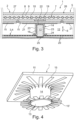
- the heat-conducting jacket 14 can be made of a material with a thermal conductivity of ⁇ > 50 W/(m K), preferably of a material with a thermal conductivity of ⁇ > 100 W/(m K). Due to the comparatively central arrangement of the support 13 in relation to the core body 11, the heat-conducting jacket 14 can theoretically also be made of a metallic material, since in the central region of the core body 11 a disturbance of a magnetic field does not occur or only occurs marginally. If the heat-conducting jacket 14 is considered according to the Fig.4 , it can be seen that it is connected to the core body 11 via radially projecting arms 15 and to the base plate 4 in a heat-transfer manner via arms 15' that also project radially. Copper or aluminum, for example, can be used as a material for the heat-conducting jacket 14, with the aim of achieving the highest possible thermal conductivity.
- the heat-conducting jacket 14 is designed as a film.
- the at least one support 13 can be made of almost any material, for example plastic, which allows a weight-optimized and lightweight design.
- the support 13 is at least partially made of graphite or ceramic, in particular aluminum nitride or aluminum silicide, or at least partially made of metal, in particular aluminum.
- a metallic design of the support 13 is also conceivable, since this is in the central area of the respective part to be supported. core body 11, in which any magnetic field present is small or non-existent.
- a so-called thermal interface material (TIM) 16 can also be provided, wherein the thermal interface material 16 has, for example, a thermally conductive adhesive, a thermal paste or an adhesive film with a thermal conductivity of ⁇ > 0.8 W/(m ⁇ K).
- the floor assembly 1 according to the invention is shown there during an assembly state, in which the arms 15' are already connected to the base plate 4 via, for example, the thermal interface material 16 and the heat-conducting jacket 14 is also connected to the support 13 via such a thermal interface material 16.
- a thermal interface material 16 is already applied to the upper arms 15, with the outer ends of the arms 15 being bent over, whereby a simplified assembly can be achieved.
- a pin 17 protruding in the spacing direction 7 in the direction of the core body 11 can be provided on the base plate 4 and on the associated support 13, a complementary opening 18 can be provided.
- At least one pressure platform 19 arranged coaxially to the associated support 13 can be provided on the lower strand carrier 10, via which the lower strand carrier 10 and thus also the flat coil 7 rests on the associated core body 11. This can ensure that the core body 11 is subjected to pressure loads exclusively via the pressure platform 19 and not to bending loads.
- the base plate 4 has according to the Fig. 1 to 3 at least one cooling channel 20 for a coolant, whereby active cooling of the base plate 3 and, via the heat-conducting jackets 14, also of the respective core body 11 and thus of the charging device 2 is possible.
- the base plate 4 itself can be made of metal, in particular of metal, in particular of aluminum.
- a distributor plate 21 is arranged between the support 13 and the associated core body 11 supported by the support 13, wherein the distributor plate 21 is connected to the Core body 11 is connected.
- a distributor plate 21 enables both mechanical fixation and improved heat dissipation.
- the heat conducting jacket 14 is cup-shaped, with a base 22 arranged between the core body 11 and the support 13, a heat-transferring jacket 23 lying flat against the support 13 (left in Fig.3 ) and an edge 24 that transfers heat and lies flat against the base plate 4.
- the jacket 23 does not lie against the support 13, so that heat is dissipated exclusively via the heat-conducting jacket 14.
- a thermal coupling between the jacket 23 and the support 13 or between the edge 24 of the heat-conducting jacket 14 and the base plate 4 can also be achieved via a so-called thermal interface material 16.
- the support 13 penetrates the base plate 4, so that in this case the application of a thermal interface material 16 between the casing 23 and the support 13 is usually omitted.
- Such penetration of the base plate 4 can be used, for example, to individually support the floor assembly 1 according to the invention, in particular also to level out any existing unevenness.
- the support 13 is not supported on the base plate 4, but rather directly on the floor, for example via its own mortar layer 25.
- an air flow path can lead through the lower cavity 12, and an electronic component (not specified in more detail) can also be arranged in the lower cavity 12, which can be cooled by an air flow flowing in the air flow path. Due to the direct arrangement of the heat-conducting jacket 14 on the support 13, the lower cavity 12 remains free of further heat-conducting elements, which means advantages in terms of the available installation space.
- the base assembly 1 has a cover plate 26 on a side of the flat coil 7 facing away from the base plate 4 and spaced apart from it in the spacing direction 6, wherein circuit boards 27 (cf. Fig. 1 and 2 ), can be arranged.
- a large-area, closed board 27 is installed between the cover plate 26 and the strand carrier 9, as is shown in the Fig.3 is shown.
- a board 27 is then designed with a mechanical strength that allows a load located on the cover plate 26 (eg a vehicle located on it) to be passed on through this board 27 to the support structure located below the board 27, comprising at least strand carrier 9, core body 11 and support 13, without itself being damaged in the process.
- the base assembly 1 according to the invention can be used to create a comparatively light base assembly 1 which also enables effective cooling of the core body 11 and, above this, the flat coil 7 via the heat-conducting jackets 14, whereby a comparatively high charging power can be achieved.
- the base assembly 1 according to the invention also has a comparatively simple structural design which is also cost-effective.
Landscapes
- Engineering & Computer Science (AREA)
- Power Engineering (AREA)
- Computer Networks & Wireless Communication (AREA)
- Transportation (AREA)
- Mechanical Engineering (AREA)
- Cooling Or The Like Of Electrical Apparatus (AREA)
Abstract
- mit einer insbesondere als Kühlplatte (3) ausgebildeten Grundplatte (4), die sich quer zu einer Abstandsrichtung (6) plattenförmig erstreckt,
- mit zumindest einer Flachspule (7), die einen spiralförmig gewundenen Leiter (8) aufweist und in Abstandsrichtung (6) zur Grundplatte (4) beabstandet ist,
- mit zumindest einem Kernkörper (11), der sich quer zur Abstandsrichtung (6) plattenförmig erstreckt,
- wobei zwischen dem zumindest einen Kernkörper (11) und der Grundplatte (4) ein unterer Hohlraum (12) ausgebildet ist,
- wobei zwischen zumindest einem Kernkörper (11) und der Grundplatte (4) zumindest eine Stütze (13) vorgesehen ist, die sich in Abstandsrichtung (6) durch den unteren Hohlraum (12) erstreckt,
- wobei zumindest ein Wärmeleitmantel (14) vorgesehen ist, der den Kernkörper (11) und die Grundplatte (4) wärmeübertragend verbindet und zumindest eine Stütze (13) mantelartig umgibt.
Description
- Die vorliegende Erfindung betrifft eine Bodenbaugruppe für eine induktive Ladevorrichtung zum induktiven Laden eines Kraftfahrzeugs.
- Bei zumindest teilelektrisch angetriebenen Kraftfahrzeugen ist ein regelmäßiges Aufladen eines elektrischen Energiespeichers des Kraftfahrzeugs notwendig. Hierzu kann prinzipiell eine unmittelbare elektrische Verbindung zwischen dem Kraftfahrzeug und einer externen elektrischen Energiequelle, beispielsweise einem Stromanschluss, hergestellt werden. Dies erfordert jedoch eine manuelle Tätigkeit eines Benutzers.
- Ferner ist es bekannt, das Kraftfahrzeug, das heißt insbesondere dessen elektrischen Energiespeicher induktiv aufzuladen. In einer Bodenbaugruppe ("Ground Assembly") außerhalb des Kraftfahrzeugs befindet sich dazu eine Primärspule, die mit einer Sekundärspule ("Vehicle Assembly") im Kraftfahrzeug induktiv zusammenwirkt. Im Betrieb der Ladevorrichtung befindet sich das zu ladende Kraftfahrzeug auf einem Untergrund über der Bodenbaugruppe, weshalb die Bodenbaugruppe derart auszulegen ist, dass sie die Last des zu ladenden Kraftfahrzeugs tragen kann. Weiter kann im Betrieb der Ladevorrichtung in der Bodenbaugruppe durch die zu erbringende Ladeleistung Wärme entstehen, die bis zu 10% der elektrischen Ladeleistung betragen und zu einem unerwünschten Temperaturanstieg der Bodenbaugruppe und damit verbunden auch zu einem Versagen der elektrischen und/oder elektromagnetischen Komponenten führen kann.
- Um die mechanischen und thermischen Belastungen aufnehmen zu können, ist es bei bekannten Bodenbaugruppen bekannt, belastungskritische Komponenten sehr massiv auszubilden und dadurch zu überdimensionieren oder thermisch zu überwachen, um bei einer Überhitzung die Ladeleistung zu reduzieren. Der Fachmann spricht hier vom sogenannten Derating. Alternativ ist auch eine aktive Kühlung denkbar, wobei effektive Wärmeableiter oft aus Metall sind und dadurch ein Magnetfeld stören können und deren Anordnung schwierig machen. Zudem ist eine derartige aktive Kühlung aufwendig und teuer.
- Die vorliegende Erfindung beschäftigt sich deshalb mit dem Problem, für eine Bodenbaugruppe für eine induktive Ladevorrichtung der eingangs genannten Art eine verbesserte oder zumindest andere Ausführungsform anzugeben, die insbesondere die aus dem Stand der Technik bekannten Nachteile überwindet.
- Dieses Problem wird erfindungsgemäß durch den Gegenstand des unabhängigen Anspruchs 1 gelöst. Vorteilhafte Ausführungsformen sind Gegenstand der abhängigen Ansprüche.
- Die vorliegende Erfindung beruht auf dem allgemeinen Gedanken, eine Leistungsübertragung beim Laden eines Elektrofahrzeugs mittels einer erfindungsgemäßen Bodenbaugruppe mit einer Grundplatte sowie einem darüber über zumindest eine Stütze abgestützten Kernkörper und einer Flachspule dadurch zu erhöhen, dass ein konduktives Wärmeleitelement vorgesehen ist, über welches eine Wärmeableitung und damit eine Kühlung von beispielsweise einer Flachspule über die zumindest eine Stütze an die insbesondere als Kühlplatte ausgebildete Grundplatte möglich ist und dadurch eine Entwärmung bzw. eine Kühlung der Flachspule und dem Kernkörper verbessert werden kann, wodurch eine höhere Ladeleistung bei gleichem Leiterquerschnitt oder eine gleiche Ladeleistung bei geringerem Leiterquerschnitt ermöglicht wird. Zur Entwärmung des zumindest einen Kernkörpers ist dabei zumindest ein als Wärmeleitmantel ausgebildetes Wärmeleitelement vorgesehen, wobei der Wärmeleitmantel den Kernkörper und die Grundplatte wärmeübertragend verbindet und zumindest eine Stütze mantelartig umgibt. Hierdurch kann der beispielsweise als Metallfolie ausgebildete Wärmeleitmantel zusammen mit der Stütze, die beispielsweise aus Kunststoff ausgebildet sein kann, in einem Zentralbereich des abzustützenden Kernkörpers angeordnet werden, wodurch einerseits eine optimierte Lastabtragung des Kernkörpers, beispielsweise eines Ferritkörpers, in die zugehörige Stütze und zugleich eine optimierte Entwärmung des Kernkörpers erreicht werden kann, ohne dass der Wärmeleitmantel ein Magnetfeld im Kernkörper stören würde, da dieses im Zentralbereich vergleichsweise gering ist. Die erfindungsgemäße Bodenbaugruppe für eine induktive Ladevorrichtung zum induktiven Laden eines auf einem Untergrund abgestellten Kraftfahrzeugs besitzt dabei die zuvor erwähnte und insbesondere als Kühlplatte ausgebildete Grundplatte, beispielsweise eine Aluminiumplatte, die sich quer zu einer Abstandsrichtung plattenförmig erstreckt. Ebenfalls besitzt die erfindungsgemäße Bodenbaugruppe zumindest eine Flachspule, die einen spiralförmig gewundenen Leiter aufweist und in Abstandsrichtung zur Grundplatte beabstandet, das heißt oberhalb derselben angeordnet ist. Des Weiteren weist die erfindungsgemäße Bodenbaugruppe zumindest einen Kernkörper, der sich quer zur Abstandsrichtung plattenförmig erstreckt und beispielsweise als Ferritkörper ausgebildet ist, auf. Zwischen dem zumindest einen Kernkörper und der Grundplatte ist dabei ein unterer Hohlraum ausgebildet, in welchem beispielsweise ein Kühlluft strömen und/oder Elektronikkomponenten angeordnet werden können. Zwischen dem zumindest einen Kernkörper und der Grundplatte ist dabei zumindest eine Stütze vorgesehen, die sich in Abstandsrichtung durch den unteren Hohlraum erstreckt, wobei zumindest ein Wärmeleitmantel vorgesehen ist, der den Kernkörper und die Grundplatte wärmeübertragend verbindet und zumindest eine Stütze mantelartig umgibt. Durch die gewählte Anordnung des Wärmeleitmantels um die Stütze herum kann der zwischen den einzelnen Stützen und zwischen dem Kernkörper und der Grundplatte vorhandene untere Hohlraum frei von Wärmeleitelementen gehalten werden, wodurch sich hier ein vergleichsweise großer und frei bestückbarer Bauraum ergibt. Durch den erfindungsgemäß vorgesehenen Wärmeleitmantel ist auch eine Bodenbaugruppe mit hoher Ladeleistung möglich, da die Kernkörper, beispielsweise Ferritplatten, mit hoher Kühlleistung entwärmt werden können. Zudem ist die erfindungsgemäße Bodenbaugruppe wenig komplex, das heißt konstruktiv einfach aufgebaut und kann dadurch kostengünstig und einfach gefertigt werden. Ist die zumindest eine Stütze zudem noch in einem Zentralbereich des jeweiligen Kernkörpers angeordnet, so beeinflusst weder sie, sofern sie beispielsweise aus Metall ausgebildet ist, noch der diese Stütze umgebende Wärmeleitmantel das magnetische Feld im Kernkörper, wodurch keine negativen Interaktionen zu befürchten sind. Durch eine Anordnung der Stütze im Zentralbereich des jeweiligen zugehörigen Kernkörpers kann vorzugsweise auch eine reine Druckbelastung in den Kernkörpern erzeugt werden, was belastungstechnisch günstig ist, da derartige Kernkörper, beispielsweise Ferrite, äußerst druckstabil, gleichzeitig aber biegesensibel sind. Die Stütze kann dabei quer zur Abstandsrichtung innerhalb eines solchen Zentralbereichs eines zugehörigen Kernkörpers angeordnet sein, wobei der Zentralbereich beispielsweise 80 % eines Durchmessers des jeweils zugehörigen Kernkörpers jeweils in Längsrichtung und Breitenrichtung, vorzugsweise 70 % des Durchmessers der einzelnen Kernkörper jeweils in Längsrichtung und in Breitenrichtung, besonders bevorzugt 50 oder gar 30 % des Durchmessers der einzelnen Kernkörper jeweils in Längsrichtung und Breitenrichtung beträgt.
- Die erfindungsgemäße Bodenbaugruppe kann versenkt in einem Untergrund, insbesondere oberflächenfluchtend zu diesem angeordnet sein, wobei alternativ selbstverständlich auch eine Anordnung auf dem Untergrund denkbar ist.
- Bei einer vorteilhaften Weiterbildung der erfindungsgemäßen Lösung ist der Wärmeleitmantel aus einem Material mit einer Wärmeleitfähigkeit von λ > 50 W/(m K), insbesondere einer Wärmeleitfähigkeit von λ > 100 W/(m·K), auf. Als Material für die jeweiligen Wärmeleitmäntel kann somit beispielsweise Aluminium mit einer Wärmeleitfähigkeit λ von 235 W/(m K) in Frage kommen.
- Zweckmäßig ist die zumindest eine Stütze aus Kunststoff ausgebildet. Eine derartige Ausbildung aus Kunststoff ermöglicht eine leichte Bauweise der erfindungsgemäßen Bodenbaugruppe, was insbesondere Wartungsarbeiten stark vereinfacht. Trotzdem können derartige Kunststoffstützen hohe Tragfähigkeiten aufweisen und dadurch die beim Überfahren auftretenden mechanischen Belastungen problemlos abtragen.
- Alternativ ist die zumindest eine Stütze zumindest teilweise aus Metall, insbesondere aus Aluminium, ausgebildet. Wiederum alternativ ist auch denkbar, dass die zumindest eine Stütze teilweise aus Grafit oder aus Keramik, insbesondere aus Aluminiumnitrid oder Aluminiumsilizid ausgebildet ist. Grafit besitzt dabei eine Wärmeleitfähigkeit λ von 15 bis 20 W/(m·K), während eine Aluminiumnitridkeramik sogar eine Leitfähigkeit λ von 180 W/(m K) besitzen kann. Der Einsatz insbesondere derartiger Aluminiumnitridkeramiken ist insbesondere dort von großem Interesse, wo viel Wärme abgeführt werden muss, ein Werkstoff jedoch unter Umständen nicht elektrisch leitend sein darf. Mit einer möglichen Positionierung im Zentralbereich ist es möglich, metallische Stützen sowohl zur Lastableitung als auch zur Wärmeableitung und damit zur Entwärmung bzw. Kühlung der Flachspule bzw. der Kernanordnung ohne bzw. mit nur marginalem Einfluss auf das Magnetfeld einzusetzen.
- Bei einer weiteren vorteilhaften Ausführungsform der erfindungsgemäßen Bodenbaugruppe weist der Wärmeleitmantel Kupfer, Aluminium und/oder Grafit auf. Bereits diese nicht abschließende Aufzählung lässt erahnen, welch mannigfaltige Möglichkeiten für das Material des Wärmeleitmantels zur Verfügung stehen, da dieser keinerlei Tragfunktion, sondern lediglich eine Wärmeleitfunktion und damit eine Entwärmung der Kernkörper bzw. eine Kühlung derselben bewirken muss.
- Besonders Metalle wie Aluminium und Kupfer weisen dabei eine hohe Wärmeleitfähigkeit und damit eine hohe Möglichkeit der Kühlung der Kernkörper durch eine Wärmeabfuhr über die Wärmeleitmäntel in die Grundplatte auf. Zusätzlich oder alternativ kann der Wärmeleitmantel auch als Folie ausgebildet sein, wodurch eine besonders dünne und auch gewichtsoptimierte Ausbildung möglich ist. Da insbesondere Aluminium eine hohe Wärmeleitfähigkeit von ca. 235 W/(m K) aufweist, kann der Wärmeleitmantel aus vergleichsweise dünnem Material ausgebildet sein und trotzdem seine wärmeableitende Funktion problemlos übernehmen.
- Zweckmäßig ist der Wärmeleitmantel wärmeübertragend, insbesondere flächig, mit zumindest einem der nachfolgenden Bauteile verbunden: Grundplatte, Stütze, Kernkörper. Hierdurch ist eine optimierte Wärmeableitung aus dem Kernkörper, beispielsweise der Ferritplatte, entweder direkt über den Wärmeleitmantel in die Grundplatte oder bei einer flächigen Anbindung an die Stütze auch über die Stütze in die Grundplatte möglich.
- Bei einer weiteren vorteilhaften Ausführungsform der erfindungsgemäßen Baugruppe ist der Wärmeleitmantel über ein thermisches Interfacematerial (TIM), insbesondere über einen Klebstoff, eine Wärmeleitpaste oder eine Klebefolie mit einer Wärmeleitfähigkeit von λ > 0,8 W/(m.K) mit zumindest der Grundplatte und/oder dem Kernkörper bzw. der Stütze verbunden. Wird als Wärmeleitmantel beispielsweise eine Aluminiumfolie verwendet, so ist bei einer Anbindung an die vorzugsweise ebenfalls aus Aluminium ausgebildete Grundplatte lediglich ein hoher Wärmeübertrag zu beachten, während bei einer Anbindung des als Aluminiumfolie ausgebildeten Wärmeleitmantels an den als Ferritkörper ausgebildeten Kernkörper auch eine Korrosionsproblematik zu beachten ist, so dass in diesem Fall eine Anbindung über ein derartiges thermisches Interfacematerial von großem Vorteil ist, da zwischen dem Wärmeleitmantel und dem Kernkörper kein direkter Kontakt besteht, so dass keine Kontaktkorrosion auftreten kann.
- Zweckmäßig sind an der Grundplatte ein in Abstandsrichtung abstehender Pin und an der zugehörigen Stütze eine komplementär dazu ausgebildete Öffnung vorgesehen. Der Pin kann dabei vorzugsweise formschlüssig in die Öffnung der Stütze eingreifen, so dass bei einer geeigneten Querschnittsform des Pins eine vordefinierte Drehwinkellage der Stütze erzwungen werden kann. Ist der Pin beispielsweise rund und die zugehörige komplementäre Öffnung ebenfalls, so kann die Stütze über ihre Achse relativ zum Pin verdreht werden, was nicht möglich ist, sofern der Pin beispielsweise einen eckigen Außenquerschnitt aufweist und die Öffnung einen komplementär dazu ausgebildeten, eckigen Innenquerschnitt. Durch eine derartige eckige Ausgestaltung des Pins und der Öffnung ist jedoch nicht nur eine Ausrichtung der Stütze relativ zur Grundplatte, sondern zugleich auch des Wärmeleitmantels möglich, was insbesondere dann vorteilhaft ist, wenn der obere Abschluss des Wärmeleitmantels die geometrisch flächige Ausdehnung des Kernkörpers in seiner Einbaulage abbildet bzw. näherungsweise abbildet. Der Pin und die zugehörige Öffnung sichern die Stütze quer zur Abstandsrichtung.
- Bei einer weiteren vorteilhaften Ausführungsform der erfindungsgemäßen Bodenbaugruppe weist die Flachspule einen Litzenträger auf, der zumindest ein koaxial zu einer zugehörigen Stütze angeordnetes Druckpodest besitzt, über welches der Litzenträger auf einem zugehörigen Kernkörper aufliegt. Das Druckpodest ist dabei bezüglich einer sich in Abstandsrichtung erstreckenden Achse koaxial zur Stütze angeordnet, wodurch es möglich ist, Lasten, wie beispielsweise von auf der Bodenbaugruppe fahrenden Kraftfahrzeugen, ausschließlich als Drucklasten und nicht als Biegelasten in die Kernkörper und von diesen in die jeweiligen Stützen einzuleiten. Da insbesondere Ferrit äußerst druckstabil ist, kann ein aus einem solchen Material bestehender Kernkörper eine reine Druckbelastung sehr gut aufnehmen. Um das Druckpodest herum ist der Litzenträger, insbesondere ein unterer Litzenträger von dem jeweiligen Kernkörper abgesetzt, das heißt in Abstandsrichtung beabstandet, sodass eine Lasteinleitung in den Kernkörper ausschließlich über das Druckpodest erfolgt. Hierdurch können sowohl die mechanische Belastbarkeit als auch die Ladeleistung der Bodenbaugruppe deutlich gesteigert werden.
- Bei einer vorteilhaften Weiterbildung weist die Grundplatte zumindest einen Kühlkanal für ein Kühlmittel auf. Hierdurch ist eine aktive Kühlung der Grundplatte im Betrieb möglich, wobei die wärmeleitenden Stützen gleichzeitig auch eine Kühlung der im Einbauzustand darüber angeordneten Kernanordnung bzw. der Kernkörper und der Flachspule bewirken. Zudem kühlt die aktiv gekühlte Grundplatte wiederum die Luft innerhalb des unteren Hohlraumes, wodurch eine Kühlung einer dort angeordneten Elektronik sowie auch eine Luftkühlung der oberhalb des unteren Hohlraums angeordneten Kernanordnung bzw. Kernkörper möglich ist. Bereiche, auf denen die jeweiligen Stützen auf der Grundplatte aufliegen, besitzen dabei vorzugsweise keine Kühlkanäle, um eine ausreichende Druckstabilität gewährleisten zu können.
- Die Grundplatte selbst ist vorteilhafterweise aus einem Metall oder einer Metalllegierung, beispielsweise Aluminium, ausgebildet, um eine Wärmeübertragung zwischen Kühlmittel, Grundplatte, Luft und Stützen zu verbessern. Durch die beabstandete Anordnung der Grundplatte zur Flachspule und der Kernanordnung wird darüber hinaus eine elektromagnetische Wechselwirkung der Grundplatte mit der Flachspule und der Kernanordnung minimiert bzw. zumindest reduziert. Ein Abstand der Grundplatte zur Kernanordnung in Abstandsrichtung kann hierbei zwischen mehreren Millimetern und mehreren Zentimetern betragen. Durch die Herstellung der Grundplatte aus Metall bzw. einer Metalllegierung erfolgt zugleich eine elektromagnetische Abschirmung der Bodenbaugruppe nach unten zum Untergrund hin. Zweckmäßig ist zwischen zumindest einer Stütze und einem zugehörigen Kernkörper eine Verteilerplatte angeordnet. Eine derartige Verteilerplatte kann eine verbesserte Wärmeübertragung und damit eine verbesserte Kühlung der Kernanordnung gewährleisten, wobei selbstverständlich klar ist, dass auch die Verteilerplatte innerhalb des Zentralbereichs angeordnet ist, um insbesondere eine Beeinflussung des Magnetfeldes und damit das Erzeugen von Wirbelstromverlusten zumindest zu minimieren. Zudem ist die Verteilerplatte mit einer Dicke < 2 mm sehr flach und dicht unterhalb der Kernanordnung angeordnet. Auch in diesem Bereich direkt unterhalb und mit Abstand zu den Abstandsbereichen der Kernanordnung ist die Magnetflussdichte im Vergleich zum Bereich zwischen den einzelnen Kernkörpern, als auch in deren Randbereich deutlich herabgesetzt, so dass auch durch den Einsatz elektrisch leitfähiger Materialien für die Verteilerplatte sich sowohl keine großen zusätzlichen Verluste durch Wirbelströme oder Hysterese-Effekte ergeben als auch der Einfluss auf das Magnetfeld sehr gering und somit vernachlässigbar ist.
- Bei einer besonders vorteilhaften Ausführungsform der erfindungsgemäßen Bodenbaugruppe ist die Verteilerplatte über eine adhäsive Schicht mit einer Wärmeleitfähigkeit von λ > 0,8 W/(m·K) und/oder einem Schubmodul von G < 10 MPa mit der Kernanordnung verbunden. Da die adhäsive Schicht, beispielsweise eine Klebstoffschicht, äußerst dünn ist, reicht hier auch eine reduzierte Wärmeleitfähigkeit λ von λ > 0,8 W/(m·K). Um darüber hinaus unterschiedliche thermische Ausdehnungskoeffizienten zwischen den Kernkörpern, beispielsweise einer Ferritplatte, und der Verteilerplatte ausgleichen zu können, ist es vorteilhaft, die Klebstoffschicht bzw. generell die adhäsive Schicht mit einem Schubmodul G < 10 MPa auszustatten.
- Zweckmäßig durchdringt zumindest eine Stütze die Grundplatte. Eine solche Variante bietet den großen Vorteil, dass durch eine punktuelle Lagerung der gesamten Bodenbaugruppe auf einem gegebenenfalls unebenen Untergrund eine Unebenheit durch punktuelle Maßnahmen, wie beispielsweise ein punktuelles Mörtelbett, ausgeglichen werden kann, ohne dass hierdurch Zwängungsbeanspruchungen an der Struktur der Bodenbaugruppe entstehen. Gegebenenfalls kann dadurch auch eine Gehäusestruktur der Bodenbaugruppe einfacher und kostengünstiger gestaltet werden. Für eine besonders einfache Montage ist es zudem denkbar, dass die Stützen vor dem Aufsetzen der Bodenbaugruppe am Untergrund positionsgenau angebracht und nivelliert werden. Zur Verstärkung der mechanischen Tragsäulen, das heißt der Stützen, kann eine Anbindung auch durch weitere Verbindungsmittel, wie beispielsweise Schrauben unterstützt werden. Zur Aufnahme von lateralen Lasten, beispielsweise resultierend aus einem Anfahren eines Kraftfahrzeugs, kann die Bodenbaugruppe zusätzlich umlaufend an zumindest drei, vorzugsweise an vier bis acht Punkten umlaufend über den Umfang der Bodenbaugruppe mittels Bolzen im Untergrund fixiert werden.
- Zweckmäßig ist zumindest ein Wärmeleitmantel becherförmig ausgebildet, mit einem zwischen Kernkörper und Stütze angeordneten Boden, einem insbesondere wärmeübertragend und flächig an der Stütze anliegenden Mantel und einem wärmeübertragend und flächig an der Grundplatte anliegenden Rand. Durch eine derartige becherförmige Ausbildung des Wärmeleitmantels kann eine zuverlässige Abdichtung der Bodenbaugruppe geschaffen werden, wodurch insbesondere auch die im vorherigen Absatz beschriebene die Grundplatte durchdringende Stütze realisierbar ist. Dabei ist der becherförmige Wärmeleitmantel mit seinem vorzugsweise kreisrunden Rand dicht mit der Grundplatte verbunden, beispielsweise verlötet, und damit ebenfalls optimiert wärmeübertragend verbunden. Zwischen der Stütze und dem Boden des Wärmeleitmantels bzw. zwischen dem Boden des Wärmeleitmantels und dem Kernkörper können dabei ebenfalls eine Wärmeleitpaste, ein Wärmeleitpad oder eine wärmeleitende Verteilerplatte angeordnet sein.
- Zweckmäßig führt durch den unteren Hohlraum ein Luftströmungspfad. Hierdurch kann eine weitere verbesserte Kühlung der den unteren Hohlraum nach oben begrenzenden Kernkörper erreicht werden, da diese über in den Luftströmungspfad strömende Kühlluft gekühlt werden können. Durch die erfindungsgemäße Ausgestaltung des zumindest einen Wärmeleitmantels direkt als die jeweilige Stütze umgebenden Mantel, bleibt auch der untere Hohlraum frei von Wärmeleitelementen, so dass dieser effektiv zur Anordnung, beispielsweise elektronischer Bauteile, genutzt werden kann.
- Bei einer weiteren vorteilhaften Ausführungsform der erfindungsgemäßen Bodenbaugruppe weist diese auf einer von der Grundplatte abgewandten Seite der Flachspule und in Abstandsrichtung zu dieser beabstandet eine Deckplatte auf, wobei zwischen der Flachspule und der Deckplatte eine Platine angeordnet ist. Hierdurch ist eine bauraumoptimierte Unterbringung derartiger elektronischer Bauteile, wie beispielsweise Platinen, denkbar.
- Weitere wichtige Merkmale und Vorteile der Erfindung ergeben sich aus den Unteransprüchen, aus den Zeichnungen und aus der zugehörigen Figurenbeschreibung anhand der Zeichnungen.
- Es versteht sich, dass die vorstehend genannten und die nachstehend noch zu erläuternden Merkmale nicht nur in der jeweils angegebenen Kombination, sondern auch in anderen Kombinationen oder in Alleinstellung verwendbar sind, ohne den Rahmen der vorliegenden Erfindung zu verlassen.
- Bevorzugte Ausführungsbeispiele der Erfindung sind in den Zeichnungen dargestellt und werden in der nachfolgenden Beschreibung näher erläutert, wobei sich gleiche Bezugszeichen auf gleiche oder ähnliche oder funktional gleiche Komponenten beziehen.
- Dabei zeigen, jeweils schematisch,
- Fig. 1
- einen Schnitt durch eine erfindungsgemäße Bodenbaugruppe einer induktiven Ladevorrichtung,
- Fig. 2
- eine Darstellung wie in
Fig. 1 , jedoch in montiertem Zustand, - Fig. 3
- eine Darstellung wie in
Fig. 1 , jedoch bei einer anderen Ausführungsform eines Wärmeleitmantels, - Fig. 4
- eine Ansicht von unten auf eine mögliche Ausführungsform eines Wärmeleitmantels.
- Entsprechend den
Fig. 1 bis 3 , weist eine erfindungsgemäße Bodenbaugruppe 1 für eine induktive Ladevorrichtung 2 zum induktiven Laden eines auf einem Untergrund 5 abgestellten und nicht näher bezeichneten Kraftfahrzeugs eine als Kühlplatte 3 ausgebildete Grundplatte 4 auf, die sich quer zu einer Abstandsrichtung 6 plattenförmig erstreckt. Ebenfalls vorgesehen ist zumindest eine Flachspule 7, die einen spiralförmig gebundenen Leiter 8 aufweist und in Abstandsrichtung 6 zur Grundplatte 4 beabstandet ist. Der Leiter 8 ist dabei zwischen einem oberen Litzenträger 9 und einem unteren Litzenträger 10 eingelegt. Ebenfalls vorgesehen ist zumindest ein Kernkörper 11, der beispielsweise als Ferritplatte ausgebildet ist, und sich quer zur Abstandsrichtung 6 plattenförmig erstreckt. Zwischen dem zumindest einen Kernkörper 11 und der Grundplatte 4 ist dabei ein unterer Hohlraum 12 ausgebildet. Getragen wird die Flachspule 7 bzw. der Kernkörper 11 von einer Stütze 13, die zwischen dem Kernkörper 11 und der Grundplatte 4 angeordnet ist und sich in Abstandsrichtung 6 durch den Hohlraum 12 erstreckt. Erfindungsgemäß ist nun zumindest ein Wärmeleitmantel 14 vorgesehen, der den Kernkörper 11, das heißt beispielsweise die Ferritplatte, und die Grundplatte 4 wärmeübertragend verbindet und zumindest eine Stütze 13 mantelartig umgibt. Über den Wärmeleitmantel 14 ist somit eine Entwärmung des Kernkörpers 11 und damit eine Kühlung desselben möglich, wodurch eine Ladeleistung der Ladevorrichtung 2 erhöht werden kann. - Der Wärmeleitmantel 14 kann dabei aus einem Material mit einer Wärmeleitfähigkeit von λ > 50 W/(m K), vorzugsweise aus einem Material mit einer Wärmeleitfähigkeit von λ > 100 W/(m·K), ausgebildet sein. Durch die vergleichsweise zentrale Anordnung der Stütze 13 in Bezug auf den Kernkörper 11 kann der Wärmeleitmantel 14 rein theoretisch auch aus einem metallischen Material ausgebildet sein, da in dem Zentralbereich des Kernkörpers 11 eine Störung eines Magnetfelds nicht oder nur marginal auftritt. Betrachtet man den Wärmeleitmantel 14 gemäß der
Fig. 4 , so kann man erkennen, dass dieser über radial abstehende Arme 15 mit dem Kernkörper 11 und über ebenfalls radial abstehende Arme 15' wärmeübertragend mit der Grundplatte 4 verbunden ist. Als Material für den Wärmeleitmantel 14 kann beispielsweise Kupfer oder Aluminium in Frage kommen, wobei eine möglichst hohe Wärmeleitfähigkeit angestrebt wird. - Um eine möglichst enge und flächige Anlage des Wärmeleitmantels 14 an die Grundplatte 4, die Stütze 13 und den zu kühlenden Kernkörper 11 erreichen zu können, ist auch denkbar, dass der Wärmeleitmantel 14 als Folie ausgebildet ist.
- Die zumindest eine Stütze 13 kann aus nahezu beliebigem Material ausgebildet werden, beispielsweise aus Kunststoff, wodurch eine gewichtsoptimierte und leichte Ausbildung möglich ist. Alternativ ist auch denkbar, dass die Stütze 13 zumindest teilweise aus Grafit oder aus Keramik, insbesondere aus Aluminiumnitrid oder Aluminiumsilizid ausgebildet ist, oder zumindest teilweise aus Metall, insbesondere aus Aluminium. Auch eine metallische Ausbildung der Stütze 13 ist denkbar, da diese im Zentralbereich des jeweils abzustützenden Kernkörpers 11 angeordnet ist, in welchem ein gegebenenfalls vorhandenes Magnetfeld klein oder gar nicht vorhanden ist.
- Um die Anbindung des Wärmeleitmantels 14 zumindest an die Grundplatte 4 und an den zu kühlenden Kernkörper 11 weiter zu verbessern, kann auch ein sogenanntes thermisches Interfacematerial (TIM) 16 vorgesehen sein, wobei das thermische Interfacematerial 16 beispielsweise einen wärmeleitfähigen Klebstoff, eine Wärmeleitpaste oder eine Klebefolie mit einer Wärmeleitfähigkeit von λ > 0,8 W/(m·K) aufweist. Durch ein derartiges thermisches Interfacematerial 16, welches zudem noch eine adhäsive Verbindung zwischen dem Wärmeleitmantel 14 und dem Kernkörper 11 bzw. der Grundplatte 4 ermöglicht, kann zudem eine zuverlässige Fixierung des Wärmeleitmantels 14 am Kernkörper 11, an der Grundplatte 4 und gegebenenfalls auch an der Stütze 13 erreicht werden.
- Betrachtet man die
Fig. 1 , so kann man erkennen, dass dort die erfindungsgemäße Bodenbaugruppe 1 während eines Montagezustands dargestellt ist, bei welchem die Arme 15' bereits flächig über beispielsweise das thermische Interfacematerial 16 mit der Grundplatte 4 und der Wärmeleitmantel 14 darüber hinaus über ein derartiges thermische Interfacematerial 16 mit der Stütze 13 verbunden ist. Auf den oberen Armen 15 ist bereits ein derartiges thermisches Interfacematerial 16 aufgetragen, wobei die äußeren Enden der Arme 15 umgebogen sind, wodurch eine vereinfachte Montage erreicht werden kann. Nach der Montage, der erfindungsgemäßen Bodenbaugruppe 1, wie dies gemäß derFig. 2 dargestellt ist, liegt der Kernkörper 11 auf der Stütze 13 auf und wird durch diese abgestützt und gleichzeitig liegen die Arme 15 flächig und damit wärmeübertragend an der Unterseite des jeweils zu kühlenden Kernkörpers 11 an. - Bei einer weiteren vorteilhaften Ausführungsform der erfindungsgemäßen Bodenbaugruppe 1 kann an der Grundplatte 4 eine in Abstandsrichtung 7 in Richtung des Kernkörpers 11 abstehender Pin 17 und an der zugehörigen Stütze 13 eine komplementär dazu ausgebildete Öffnung 18 vorgesehen sein. Hierdurch ist eine Vorfixierung bei der Montage der Stütze 13 an der Grundplatte 4 vergleichsweise einfach möglich, ebenso wie eine vordefinierte Ausrichtung. Eine Fixierung kann dabei ebenfalls über eine zwischen der Stütze 13 und der Grundplatte 4 angeordnete Klebeschicht, beispielsweise ein thermisches Interfacematerial 16, erfolgen. Über den Pin 17 und die zugehörige Öffnung 18 kann bei einem nicht runden Querschnitt des Pins 17 auch eine vordefinierte Drehausrichtung der Stütze 13 relativ zur Grundplatte 4 erzwungen werden. Über entsprechende an einem Rand der Öffnung 18 angeordnete Fasen kann ein Einführen des Pins 17 in die jeweilige Öffnung 18 der Stütze 13 erleichtert werden.
- Um eine optimierte Ableitung mechanischer Belastungen erreichen zu können, kann an dem unteren Litzenträger 10 zumindest ein koaxial zur zugehörigen Stütze 13 angeordnetes Druckpodest 19 vorgesehen sein, über welches der untere Litzenträger 10 und damit auch die Flachspule 7 auf dem zugehörigen Kernkörper 11 aufliegt. Hierdurch kann gewährleistet werden, dass der Kernkörper 11 ausschließlich über das Druckpodest 19 Druckbelastungen und keine Biegebelastungen erfährt.
- Die Grundplatte 4 weist gemäß den
Fig. 1 bis 3 zumindest einen Kühlkanal 20 für ein Kühlmittel auf, wodurch eine aktive Kühlung der Grundplatte 3 und über die Wärmeleitmäntel 14 auch der jeweiligen Kernkörper 11 und damit der Ladevorrichtung 2 möglich ist. Die Grundplatte 4 selbst kann aus Metall, insbesondere aus Metall, insbesondere aus Aluminium, ausgebildet sein. - Betrachtet man die
Fig. 3 , so kann man erkennen, dass zwischen der Stütze 13 und dem zugehörigen und von der Stütze 13 abgestützten Kernkörper 11 eine Verteilerplatte 21 angeordnet ist, wobei die Verteilerplatte 21 über eine nicht näher bezeichnete adhäsive Schicht aus einem Material mit einer Wärmeleitfähigkeit von λ > 0,8 W/(m K) und/oder einem Schubmodul von G < 10 MPa mit dem Kernkörper 11 verbunden ist. Durch eine derartige Verteilerplatte 21 ist sowohl eine mechanische Fixierung als auch eine verbesserte Wärmeableitung möglich. - Betrachtet man den Wärmeleitmantel 14 gemäß der
Fig. 3 , so kann man erkennen, dass dieser becherförmig ausgebildet ist, mit einem zwischen Kernkörper 11 und Stütze 13 angeordneten Boden 22, einem wärmeübertragend und flächig an der Stütze 13 anliegenden Mantel 23 (links inFig. 3 ) und einem wärmeübertragend und flächig an der Grundplatte 4 anliegenden Rand 24. Rechts liegt der Mantel 23 dabei nicht an der Stütze 13 an, so dass hier eine Wärmeableitung ausschließlich über den Wärmeleitmantel 14 erfolgt. Eine thermische Kopplung zwischen Mantel 23 und Stütze 13 bzw. zwischen Rand 24 des Wärmeleitmantels 14 und der Grundplatte 4 kann dabei ebenfalls wiederum über ein sogenanntes thermisches Interfacematerial 16 erfolgen. - Gemäß der
Fig. 3 durchdringt die Stütze 13 die Grundplatte 4, so dass in diesem Fall das Anbringen eines thermischen Interfacematerials 16 zwischen dem Mantel 23 und der Stütze 13 üblicherweise unterbleibt. Ein derartiges Durchdringen der Grundplatte 4 kann beispielsweise zu einem individuellen Abstützen der erfindungsgemäßen Bodenbaugruppe 1 genutzt werden, insbesondere auch zum Ausnivellieren eventuell bestehender Unebenheiten. Die Stütze 13 stützt sich in diesem Fall nicht auf der Grundplatte 4, sondern beispielsweise über eine eigene Mörtelschicht 25 direkt am Boden ab. - Durch den unteren Hohlraum 12 kann beispielsweise ein Luftströmungspfad führen, wobei in dem unteren Hohlraum 12 darüber hinaus ein nicht näher bezeichnetes elektronisches Bauteil angeordnet sein kann, welches durch einen in dem Luftströmungspfad strömenden Luftstrom kühlbar ist. Durch die direkte Anordnung des Wärmeleitmantels 14 an der Stütze 13 bleibt der untere Hohlraum 12 frei von weiteren Wärmeleitelementen, was Vorteile hinsichtlich des zur Verfügung stehenden Bauraums bedeutet.
- Die Bodenbaugruppe 1 ist auf einer von der Grundplatte 4 abgewandten Seite der Flachspule 7 und in Abstandsrichtung 6 zu dieser beabstandet eine Deckplatte 26 auf, wobei zwischen der Flachspule 7 und der Deckplatte 26 in entsprechenden Hohlräumen Platinen 27 (vgl.
Fig. 1 und 2 ), angeordnet sein können. - In einer alternativen Ausführungsform ist es auch denkbar, dass zwischen der Deckplatte 26 und dem Litzenträger 9 nur eine großflächige, geschlossene Platine 27 verbaut ist, wie dies gemäß der
Fig. 3 gezeigt ist. Eine solche Platine 27 ist dann mit einer mechanischen Festigkeit ausgeführt, die es erlaubt, dass eine auf der Deckplatte 26 befindliche Last (z.B. ein sich darauf befindliches Fahrzeug) durch diese Platine 27 hindurch an die sich unterhalb der Platine 27 befindliche Tragstruktur aus zumindest Litzenträger 9, Kernkörper 11 und Stütze 13 weitergeleitet werden kann, ohne dabei selbst beschädigt zu werden. - Alles in allem kann mit der erfindungsgemäßen Bodenbaugruppe 1 eine vergleichsweise leichte Bodenbaugruppe 1 geschaffen werden, die über die Wärmeleitmäntel 14 zudem eine effektive Kühlung der Kernkörper 11 und darüber der Flachspule 7 ermöglicht, wodurch eine vergleichsweise hohe Ladeleistung erzielbar ist. Alles in allem weist die erfindungsgemäße Bodenbaugruppe 1 zudem einen vergleichsweise einfachen konstruktiven Aufbau auf, der zudem kostengünstig ist.
- Mit der erfindungsgemäßen Bodenbaugruppe 1 lassen sich mehrere Vorteile erzielen:
- verbesserte Entwärmung und Belastung der Kernkörper 11 und dadurch hohe Lebensdauer und geringes Bruchrisiko, derselben,
- keine zusätzlichen aktiven Komponenten zur Verbesserung des Wärmetransportes, insbesondere keine Luftströmung,
- dünner Aufbau der thermischen Anbindung durch Verwendung von Wärmeleitmänteln 14, insbesondere aus Metall,
- freier Bauraum für Elektronik-Komponenten inkl. Befestigungsmöglichkeiten für Elektronikkomponenten,
- einfacher und kostengünstiger Aufbau,
- flexibel an Leistungsklasse und Umgebungsbedingungen anpassbar,
- Funktionsintegration von Elektromagnetik - Elektronik - Thermik - Mechanik.
Claims (15)
- Bodenbaugruppe (1) für eine induktive Ladevorrichtung (2) zum induktiven Laden eines auf einem Untergrund (5) abgestellten Kraftfahrzeugs,- mit einer insbesondere als Kühlplatte (3) ausgebildeten Grundplatte (4), die sich quer zu einer Abstandsrichtung (6) plattenförmig erstreckt,- mit zumindest einer Flachspule (7), die einen spiralförmig gewundenen Leiter (8) aufweist und in Abstandsrichtung (6) zur Grundplatte (4) beabstandet ist,- mit zumindest einem Kernkörper (11), der sich quer zur Abstandsrichtung (6) plattenförmig erstreckt,- wobei zwischen dem zumindest einen Kernkörper (11) und der Grundplatte (4) ein unterer Hohlraum (12) ausgebildet ist,- wobei zwischen zumindest einem Kernkörper (11) und der Grundplatte (4) zumindest eine Stütze (13) vorgesehen ist, die sich in Abstandsrichtung (6) durch den unteren Hohlraum (12) erstreckt,- wobei zumindest ein Wärmeleitmantel (14) vorgesehen ist, der den Kernkörper (11) und die Grundplatte (4) wärmeübertragend verbindet und zumindest eine Stütze (13) mantelartig umgibt.
- Bodenbaugruppe nach Anspruch 1,
dadurch gekennzeichnet,
dass der Wärmeleitmantel (14) aus einem Material mit einer Wärmeleitfähigkeit λ > 50 W/(m K), vorzugsweise einer Wärmeleitfähigkeit λ > 100 W/(m K), ausgebildet ist. - Bodenbaugruppe nach Anspruch 1 oder 2,
dadurch gekennzeichnet,- dass die zumindest eine Stütze (13) aus Kunststoff ausgebildet ist, oder- dass die zumindest eine Stütze (13) zumindest teilweise aus Grafit oder aus Keramik, insbesondere aus Aluminiumnitrid oder Aluminiumsilizid, ausgebildet ist, oder- dass die zumindest eine Stütze (13) zumindest teilweise aus Metall, insbesondere aus Aluminium, ausgebildet ist. - Bodenbaugruppe nach einem der vorhergehenden Ansprüche,
dadurch gekennzeichnet,- dass der Wärmleitmantel (14) Kupfer, Aluminium und/oder Grafit aufweist, und/oder- dass der Wärmeleitmantel (14) als Folie ausgebildet ist. - Bodenbaugruppe nach einem der vorhergehenden Ansprüche,
dadurch gekennzeichnet,
dass der Wärmeleitmantel (14) wärmeübertragend, insbesondere flächig, mit zumindest einem der nachfolgenden Bauteile verbunden ist, Grundplatte (4), Stütze (13), Kernkörper (11). - Bodenbaugruppe nach einem der vorherigen Ansprüche,
dadurch gekennzeichnet,- dass die wärmeübertragende, insbesondere flächige Verbindung zwischen Wärmeleitmantel (14) und Kernkörper (11) über radial vom Wärmeleitmantel (14) abstehende Arme (15) hergestellt ist, und/oder- dass die wärmeübertragende, insbesondere flächige Verbindung zwischen Wärmeleitmantel (14) und Grundplatte (4) über radial vom Wärmeleitmantel (14) abstehende Arme (15') hergestellt ist. - Bodenbaugruppe nach einem der vorhergehenden Ansprüche,
dadurch gekennzeichnet,
dass der Wärmeleitmantel (14) über ein thermisches Interface Material (16), insbesondere über einen Klebstoff, eine Wärmeleitpaste oder eine Klebefolie mit einer Wärmeleitfähigkeit λ > 0,80 W/(m·K) mit zumindest der Grundplatte (4) und dem Kernkörper (11) verbunden ist. - Bodenbaugruppe nach einem der vorhergehenden Ansprüche,
dadurch gekennzeichnet,
dass an der Grundplatte (4) ein in Abstandsrichtung (6) abstehender Pin (17) und der zugehörigen Stütze (13) eine komplementär dazu ausgebildete Öffnung (18) vorgesehen sind. - Bodenbaugruppe nach einem der vorhergehenden Ansprüche,
dadurch gekennzeichnet,
dass die Flachspule (7) einen oberen Litzenträger (9) und einen unteren Litzenträger (10) aufweist, der zumindest einen koaxial zu einer zugehörigen Stütze (13) angeordneten Druckpodest (19) aufweist, über welchen der untere Litzenträger (10) auf einem zugehörigen Kernkörper (11) aufliegt. - Bodenbaugruppe nach Anspruch 1 oder 2,
dadurch gekennzeichnet,- dass die Grundplatte (4) zumindest einen Kühlkanal (20) für ein Kühlmittel aufweist, und/oder- dass die Grundplatte (4) zumindest teilweise aus Metall, insbesondere aus Aluminium, ausgebildet ist. - Bodenbaugruppe nach einem der vorhergehenden Ansprüche,
dadurch gekennzeichnet,
dass zwischen zumindest einer Stütze (13) und einem zugehörigen Kernkörper (11) eine Verteilerplatte (21) angeordnet ist. - Bodenbaugruppe nach Anspruch 11,
dadurch gekennzeichnet,
dass die Verteilerplatte (21) über eine adhäsive Schicht aus einem Material mit einer Wärmeleitfähigkeit von λ > 0,8 W/(m·K) und/oder einem Schubmodul von G < 10 MPa mit dem Kernkörper (11) verbunden ist. - Bodenbaugruppe nach einem der vorhergehenden Ansprüche,
dadurch gekennzeichnet,- dass zumindest eine Stütze (13) die Grundplatte (4) durchdringt,- dass zumindest ein Wärmeleitmantel (14) becherförmig ausgebildet ist, mit einem zwischen Kernkörper (11) und Stütze (13) angeordneten Boden (22), einem die Stütze (13) umgebenden Mantel (23) und einem wärmeübertragend und flächig an der Grundplatte (4) anliegenden Rand (24). - Bodenbaugruppe nach einem der vorhergehenden Ansprüche,
dadurch gekennzeichnet,- dass durch den unteren Hohlraum (12) ein Luftströmungspfad führt und/oder- dass in dem unteren Hohlraum (12) zumindest ein elektronisches Bauteil angeordnet ist. - Bodenbaugruppe nach einem der vorhergehenden Ansprüche,
dadurch gekennzeichnet,- dass die Bodenbaugruppe (1) auf der von der Grundplatte (4) abgewandten Seite der Flachspule (7) und in Abstandsrichtung (6) zu dieser beabstandet eine Deckplatte (26) aufweist,- dass zwischen der Flachspule (7) und der Deckplatte (26) eine Platine (27) angeordnet ist.
Priority Applications (2)
| Application Number | Priority Date | Filing Date | Title |
|---|---|---|---|
| ES23163700T ES3062713T3 (en) | 2023-03-23 | 2023-03-23 | Ground assembly for an inductive charging device |
| EP23163700.0A EP4434804B1 (de) | 2023-03-23 | 2023-03-23 | Bodenbaugruppe für eine induktive ladevorrichtung |
Applications Claiming Priority (1)
| Application Number | Priority Date | Filing Date | Title |
|---|---|---|---|
| EP23163700.0A EP4434804B1 (de) | 2023-03-23 | 2023-03-23 | Bodenbaugruppe für eine induktive ladevorrichtung |
Publications (2)
| Publication Number | Publication Date |
|---|---|
| EP4434804A1 true EP4434804A1 (de) | 2024-09-25 |
| EP4434804B1 EP4434804B1 (de) | 2025-12-31 |
Family
ID=85727156
Family Applications (1)
| Application Number | Title | Priority Date | Filing Date |
|---|---|---|---|
| EP23163700.0A Active EP4434804B1 (de) | 2023-03-23 | 2023-03-23 | Bodenbaugruppe für eine induktive ladevorrichtung |
Country Status (2)
| Country | Link |
|---|---|
| EP (1) | EP4434804B1 (de) |
| ES (1) | ES3062713T3 (de) |
Citations (6)
| Publication number | Priority date | Publication date | Assignee | Title |
|---|---|---|---|---|
| US6049191A (en) * | 1998-02-23 | 2000-04-11 | Kabushiki Kaisha Toyoda Jidoshokki Seisakusho | Cooling structure for inductive charger coupling |
| US20170076854A1 (en) * | 2014-05-22 | 2017-03-16 | Ihi Corporation | Coil device |
| DE102017206898A1 (de) * | 2017-04-25 | 2018-10-25 | Robert Bosch Gmbh | Spule in Leichtbauweise |
| KR20210050923A (ko) * | 2019-10-29 | 2021-05-10 | 에스케이씨 주식회사 | 무선충전 패드, 무선충전 장치, 및 이를 포함하는 전기 자동차 |
| DE102021205980A1 (de) * | 2021-06-11 | 2022-12-15 | Mahle International Gmbh | Bodenbaugruppe für eine induktive Ladevorrichtung |
| DE102021205979A1 (de) * | 2021-06-11 | 2022-12-15 | Mahle International Gmbh | Bodenbaugruppe für eine induktive Ladevorrichtung |
-
2023
- 2023-03-23 ES ES23163700T patent/ES3062713T3/es active Active
- 2023-03-23 EP EP23163700.0A patent/EP4434804B1/de active Active
Patent Citations (6)
| Publication number | Priority date | Publication date | Assignee | Title |
|---|---|---|---|---|
| US6049191A (en) * | 1998-02-23 | 2000-04-11 | Kabushiki Kaisha Toyoda Jidoshokki Seisakusho | Cooling structure for inductive charger coupling |
| US20170076854A1 (en) * | 2014-05-22 | 2017-03-16 | Ihi Corporation | Coil device |
| DE102017206898A1 (de) * | 2017-04-25 | 2018-10-25 | Robert Bosch Gmbh | Spule in Leichtbauweise |
| KR20210050923A (ko) * | 2019-10-29 | 2021-05-10 | 에스케이씨 주식회사 | 무선충전 패드, 무선충전 장치, 및 이를 포함하는 전기 자동차 |
| DE102021205980A1 (de) * | 2021-06-11 | 2022-12-15 | Mahle International Gmbh | Bodenbaugruppe für eine induktive Ladevorrichtung |
| DE102021205979A1 (de) * | 2021-06-11 | 2022-12-15 | Mahle International Gmbh | Bodenbaugruppe für eine induktive Ladevorrichtung |
Also Published As
| Publication number | Publication date |
|---|---|
| ES3062713T3 (en) | 2026-04-13 |
| EP4434804B1 (de) | 2025-12-31 |
Similar Documents
| Publication | Publication Date | Title |
|---|---|---|
| EP3113278B1 (de) | Kraftfahrzeugbatterie | |
| WO2022258367A1 (de) | Bodenbaugruppe für eine induktive ladevorrichtung | |
| DE102021115705B3 (de) | Batterie für ein Kraftfahrzeug | |
| DE102014206739A1 (de) | Schubfeld für einen Vorderwagen einer Fahrzeugkarosserie eines Fahrzeugs und Fahrzeug | |
| DE102017109321A1 (de) | EMV-Filter | |
| DE102008034875A1 (de) | Batterie, insbesondere Fahrzeugbatterie | |
| WO2018197267A1 (de) | Induktionsladevorrichtung mit kühlanordnung | |
| DE102013201096A1 (de) | Batteriesystem mit Batteriezellen und einer Vorrichtung zur Temperierung der Batteriezellen | |
| DE102012213059A1 (de) | Kühlmantel | |
| WO2022258368A1 (de) | Bodenbaugruppe für eine induktive ladevorrichtung | |
| DE102016219213B4 (de) | Leistungselektronik mit direkt und aktiv gekühlter Kondensatoreinheit mittels Wärmerohren | |
| DE102019200817A1 (de) | Kühleinrichtung zur Kühlung von Batteriezellen, Batterie und Kraftfahrzeug | |
| DE102021211348A1 (de) | Bodenbaugruppe für eine induktive Ladevorrichtung | |
| DE102021211349A1 (de) | Bodenbaugruppe für eine induktive Ladevorrichtung | |
| DE2458846A1 (de) | Elektronische baugruppe mit halbleiterschaltungen | |
| WO2019137748A1 (de) | Steuereinrichtung zum ansteuern eines e-motors | |
| EP3758130B1 (de) | Aufnahmevorrichtung zur aufnahme und kühlung von einschubmodulen | |
| EP4434804B1 (de) | Bodenbaugruppe für eine induktive ladevorrichtung | |
| EP2599370A1 (de) | Anordnung und energiespeicher mit einer anordnung zum temperieren, insbesondere kühlen, von wärmeerzeugenden bauelementen | |
| DE102018215522A1 (de) | Zwischenkreiskondensator für eine Leistungselektronikanordnung sowie Leistungselektronikanordnung mit dem Zwischenkreiskondensator | |
| WO2023186365A1 (de) | Stationäre bodenbaugruppe für eine induktive ladevorrichtung | |
| DE102017009640A1 (de) | Kühlvorrichtung | |
| WO2022258364A1 (de) | Bodenbaugruppe für eine induktive ladevorrichtung | |
| WO2024120960A1 (de) | Induktionsladevorrichtung | |
| WO2024121008A1 (de) | Stationäre induktionsladevorrichtung sowie induktives fahrzeugladesystem mit derselben |
Legal Events
| Date | Code | Title | Description |
|---|---|---|---|
| PUAI | Public reference made under article 153(3) epc to a published international application that has entered the european phase |
Free format text: ORIGINAL CODE: 0009012 |
|
| STAA | Information on the status of an ep patent application or granted ep patent |
Free format text: STATUS: THE APPLICATION HAS BEEN PUBLISHED |
|
| AK | Designated contracting states |
Kind code of ref document: A1 Designated state(s): AL AT BE BG CH CY CZ DE DK EE ES FI FR GB GR HR HU IE IS IT LI LT LU LV MC ME MK MT NL NO PL PT RO RS SE SI SK SM TR |
|
| STAA | Information on the status of an ep patent application or granted ep patent |
Free format text: STATUS: REQUEST FOR EXAMINATION WAS MADE |
|
| 17P | Request for examination filed |
Effective date: 20241204 |
|
| RBV | Designated contracting states (corrected) |
Designated state(s): AL AT BE BG CH CY CZ DE DK EE ES FI FR GB GR HR HU IE IS IT LI LT LU LV MC ME MK MT NL NO PL PT RO RS SE SI SK SM TR |
|
| STAA | Information on the status of an ep patent application or granted ep patent |
Free format text: STATUS: EXAMINATION IS IN PROGRESS |
|
| 17Q | First examination report despatched |
Effective date: 20250326 |
|
| GRAP | Despatch of communication of intention to grant a patent |
Free format text: ORIGINAL CODE: EPIDOSNIGR1 |
|
| STAA | Information on the status of an ep patent application or granted ep patent |
Free format text: STATUS: GRANT OF PATENT IS INTENDED |
|
| RIC1 | Information provided on ipc code assigned before grant |
Ipc: B60L 53/12 20190101AFI20250722BHEP Ipc: B60L 53/302 20190101ALI20250722BHEP Ipc: H01F 27/02 20060101ALI20250722BHEP Ipc: H01F 27/08 20060101ALI20250722BHEP Ipc: H01F 27/22 20060101ALI20250722BHEP Ipc: H01F 27/30 20060101ALI20250722BHEP Ipc: H01F 27/36 20060101ALI20250722BHEP Ipc: H01F 27/26 20060101ALI20250722BHEP Ipc: H01F 38/14 20060101ALI20250722BHEP Ipc: H02J 50/00 20160101ALI20250722BHEP Ipc: H02J 50/12 20160101ALI20250722BHEP |
|
| INTG | Intention to grant announced |
Effective date: 20250811 |
|
| GRAS | Grant fee paid |
Free format text: ORIGINAL CODE: EPIDOSNIGR3 |
|
| GRAA | (expected) grant |
Free format text: ORIGINAL CODE: 0009210 |
|
| STAA | Information on the status of an ep patent application or granted ep patent |
Free format text: STATUS: THE PATENT HAS BEEN GRANTED |
|
| AK | Designated contracting states |
Kind code of ref document: B1 Designated state(s): AL AT BE BG CH CY CZ DE DK EE ES FI FR GB GR HR HU IE IS IT LI LT LU LV MC ME MK MT NL NO PL PT RO RS SE SI SK SM TR |
|
| REG | Reference to a national code |
Ref country code: CH Ref legal event code: F10 Free format text: ST27 STATUS EVENT CODE: U-0-0-F10-F00 (AS PROVIDED BY THE NATIONAL OFFICE) Effective date: 20251231 Ref country code: GB Ref legal event code: FG4D Free format text: NOT ENGLISH |
|
| REG | Reference to a national code |
Ref country code: DE Ref legal event code: R096 Ref document number: 502023002617 Country of ref document: DE |
|
| REG | Reference to a national code |
Ref country code: IE Ref legal event code: FG4D Free format text: LANGUAGE OF EP DOCUMENT: GERMAN |
|
| REG | Reference to a national code |
Ref country code: LT Ref legal event code: MG9D |
|
| PG25 | Lapsed in a contracting state [announced via postgrant information from national office to epo] |
Ref country code: NO Free format text: LAPSE BECAUSE OF FAILURE TO SUBMIT A TRANSLATION OF THE DESCRIPTION OR TO PAY THE FEE WITHIN THE PRESCRIBED TIME-LIMIT Effective date: 20260331 |
|
| REG | Reference to a national code |
Ref country code: ES Ref legal event code: FG2A Ref document number: 3062713 Country of ref document: ES Kind code of ref document: T3 Effective date: 20260413 |
|
| PG25 | Lapsed in a contracting state [announced via postgrant information from national office to epo] |
Ref country code: FI Free format text: LAPSE BECAUSE OF FAILURE TO SUBMIT A TRANSLATION OF THE DESCRIPTION OR TO PAY THE FEE WITHIN THE PRESCRIBED TIME-LIMIT Effective date: 20251231 Ref country code: HR Free format text: LAPSE BECAUSE OF FAILURE TO SUBMIT A TRANSLATION OF THE DESCRIPTION OR TO PAY THE FEE WITHIN THE PRESCRIBED TIME-LIMIT Effective date: 20251231 |
|
| PGFP | Annual fee paid to national office [announced via postgrant information from national office to epo] |
Ref country code: AT Payment date: 20260301 Year of fee payment: 4 |
|
| PG25 | Lapsed in a contracting state [announced via postgrant information from national office to epo] |
Ref country code: RS Free format text: LAPSE BECAUSE OF FAILURE TO SUBMIT A TRANSLATION OF THE DESCRIPTION OR TO PAY THE FEE WITHIN THE PRESCRIBED TIME-LIMIT Effective date: 20260331 |
|
| PG25 | Lapsed in a contracting state [announced via postgrant information from national office to epo] |
Ref country code: LV Free format text: LAPSE BECAUSE OF FAILURE TO SUBMIT A TRANSLATION OF THE DESCRIPTION OR TO PAY THE FEE WITHIN THE PRESCRIBED TIME-LIMIT Effective date: 20251231 |