EP4434798A1 - Battery electric vehicle - Google Patents
Battery electric vehicle Download PDFInfo
- Publication number
- EP4434798A1 EP4434798A1 EP24164792.4A EP24164792A EP4434798A1 EP 4434798 A1 EP4434798 A1 EP 4434798A1 EP 24164792 A EP24164792 A EP 24164792A EP 4434798 A1 EP4434798 A1 EP 4434798A1
- Authority
- EP
- European Patent Office
- Prior art keywords
- torque
- electric vehicle
- battery electric
- travel mode
- shift
- Prior art date
- Legal status (The legal status is an assumption and is not a legal conclusion. Google has not performed a legal analysis and makes no representation as to the accuracy of the status listed.)
- Pending
Links
Images


Classifications
-
- B—PERFORMING OPERATIONS; TRANSPORTING
- B60—VEHICLES IN GENERAL
- B60L—PROPULSION OF ELECTRICALLY-PROPELLED VEHICLES; SUPPLYING ELECTRIC POWER FOR AUXILIARY EQUIPMENT OF ELECTRICALLY-PROPELLED VEHICLES; ELECTRODYNAMIC BRAKE SYSTEMS FOR VEHICLES IN GENERAL; MAGNETIC SUSPENSION OR LEVITATION FOR VEHICLES; MONITORING OPERATING VARIABLES OF ELECTRICALLY-PROPELLED VEHICLES; ELECTRIC SAFETY DEVICES FOR ELECTRICALLY-PROPELLED VEHICLES
- B60L15/00—Methods, circuits, or devices for controlling the traction-motor speed of electrically-propelled vehicles
- B60L15/20—Methods, circuits, or devices for controlling the traction-motor speed of electrically-propelled vehicles for control of the vehicle or its driving motor to achieve a desired performance, e.g. speed, torque, programmed variation of speed
- B60L15/2054—Methods, circuits, or devices for controlling the traction-motor speed of electrically-propelled vehicles for control of the vehicle or its driving motor to achieve a desired performance, e.g. speed, torque, programmed variation of speed by controlling transmissions or clutches
-
- B—PERFORMING OPERATIONS; TRANSPORTING
- B60—VEHICLES IN GENERAL
- B60L—PROPULSION OF ELECTRICALLY-PROPELLED VEHICLES; SUPPLYING ELECTRIC POWER FOR AUXILIARY EQUIPMENT OF ELECTRICALLY-PROPELLED VEHICLES; ELECTRODYNAMIC BRAKE SYSTEMS FOR VEHICLES IN GENERAL; MAGNETIC SUSPENSION OR LEVITATION FOR VEHICLES; MONITORING OPERATING VARIABLES OF ELECTRICALLY-PROPELLED VEHICLES; ELECTRIC SAFETY DEVICES FOR ELECTRICALLY-PROPELLED VEHICLES
- B60L15/00—Methods, circuits, or devices for controlling the traction-motor speed of electrically-propelled vehicles
- B60L15/20—Methods, circuits, or devices for controlling the traction-motor speed of electrically-propelled vehicles for control of the vehicle or its driving motor to achieve a desired performance, e.g. speed, torque, programmed variation of speed
-
- B—PERFORMING OPERATIONS; TRANSPORTING
- B60—VEHICLES IN GENERAL
- B60L—PROPULSION OF ELECTRICALLY-PROPELLED VEHICLES; SUPPLYING ELECTRIC POWER FOR AUXILIARY EQUIPMENT OF ELECTRICALLY-PROPELLED VEHICLES; ELECTRODYNAMIC BRAKE SYSTEMS FOR VEHICLES IN GENERAL; MAGNETIC SUSPENSION OR LEVITATION FOR VEHICLES; MONITORING OPERATING VARIABLES OF ELECTRICALLY-PROPELLED VEHICLES; ELECTRIC SAFETY DEVICES FOR ELECTRICALLY-PROPELLED VEHICLES
- B60L50/00—Electric propulsion with power supplied within the vehicle
- B60L50/50—Electric propulsion with power supplied within the vehicle using propulsion power supplied by batteries or fuel cells
- B60L50/60—Electric propulsion with power supplied within the vehicle using propulsion power supplied by batteries or fuel cells using power supplied by batteries
-
- B—PERFORMING OPERATIONS; TRANSPORTING
- B60—VEHICLES IN GENERAL
- B60L—PROPULSION OF ELECTRICALLY-PROPELLED VEHICLES; SUPPLYING ELECTRIC POWER FOR AUXILIARY EQUIPMENT OF ELECTRICALLY-PROPELLED VEHICLES; ELECTRODYNAMIC BRAKE SYSTEMS FOR VEHICLES IN GENERAL; MAGNETIC SUSPENSION OR LEVITATION FOR VEHICLES; MONITORING OPERATING VARIABLES OF ELECTRICALLY-PROPELLED VEHICLES; ELECTRIC SAFETY DEVICES FOR ELECTRICALLY-PROPELLED VEHICLES
- B60L2240/00—Control parameters of input or output; Target parameters
- B60L2240/10—Vehicle control parameters
- B60L2240/30—Parking brake position
-
- B—PERFORMING OPERATIONS; TRANSPORTING
- B60—VEHICLES IN GENERAL
- B60L—PROPULSION OF ELECTRICALLY-PROPELLED VEHICLES; SUPPLYING ELECTRIC POWER FOR AUXILIARY EQUIPMENT OF ELECTRICALLY-PROPELLED VEHICLES; ELECTRODYNAMIC BRAKE SYSTEMS FOR VEHICLES IN GENERAL; MAGNETIC SUSPENSION OR LEVITATION FOR VEHICLES; MONITORING OPERATING VARIABLES OF ELECTRICALLY-PROPELLED VEHICLES; ELECTRIC SAFETY DEVICES FOR ELECTRICALLY-PROPELLED VEHICLES
- B60L2240/00—Control parameters of input or output; Target parameters
- B60L2240/40—Drive Train control parameters
- B60L2240/42—Drive Train control parameters related to electric machines
- B60L2240/423—Torque
-
- B—PERFORMING OPERATIONS; TRANSPORTING
- B60—VEHICLES IN GENERAL
- B60L—PROPULSION OF ELECTRICALLY-PROPELLED VEHICLES; SUPPLYING ELECTRIC POWER FOR AUXILIARY EQUIPMENT OF ELECTRICALLY-PROPELLED VEHICLES; ELECTRODYNAMIC BRAKE SYSTEMS FOR VEHICLES IN GENERAL; MAGNETIC SUSPENSION OR LEVITATION FOR VEHICLES; MONITORING OPERATING VARIABLES OF ELECTRICALLY-PROPELLED VEHICLES; ELECTRIC SAFETY DEVICES FOR ELECTRICALLY-PROPELLED VEHICLES
- B60L2240/00—Control parameters of input or output; Target parameters
- B60L2240/40—Drive Train control parameters
- B60L2240/44—Drive Train control parameters related to combustion engines
- B60L2240/443—Torque
-
- B—PERFORMING OPERATIONS; TRANSPORTING
- B60—VEHICLES IN GENERAL
- B60L—PROPULSION OF ELECTRICALLY-PROPELLED VEHICLES; SUPPLYING ELECTRIC POWER FOR AUXILIARY EQUIPMENT OF ELECTRICALLY-PROPELLED VEHICLES; ELECTRODYNAMIC BRAKE SYSTEMS FOR VEHICLES IN GENERAL; MAGNETIC SUSPENSION OR LEVITATION FOR VEHICLES; MONITORING OPERATING VARIABLES OF ELECTRICALLY-PROPELLED VEHICLES; ELECTRIC SAFETY DEVICES FOR ELECTRICALLY-PROPELLED VEHICLES
- B60L2240/00—Control parameters of input or output; Target parameters
- B60L2240/40—Drive Train control parameters
- B60L2240/48—Drive Train control parameters related to transmissions
-
- B—PERFORMING OPERATIONS; TRANSPORTING
- B60—VEHICLES IN GENERAL
- B60L—PROPULSION OF ELECTRICALLY-PROPELLED VEHICLES; SUPPLYING ELECTRIC POWER FOR AUXILIARY EQUIPMENT OF ELECTRICALLY-PROPELLED VEHICLES; ELECTRODYNAMIC BRAKE SYSTEMS FOR VEHICLES IN GENERAL; MAGNETIC SUSPENSION OR LEVITATION FOR VEHICLES; MONITORING OPERATING VARIABLES OF ELECTRICALLY-PROPELLED VEHICLES; ELECTRIC SAFETY DEVICES FOR ELECTRICALLY-PROPELLED VEHICLES
- B60L2240/00—Control parameters of input or output; Target parameters
- B60L2240/40—Drive Train control parameters
- B60L2240/48—Drive Train control parameters related to transmissions
- B60L2240/486—Operating parameters
-
- B—PERFORMING OPERATIONS; TRANSPORTING
- B60—VEHICLES IN GENERAL
- B60L—PROPULSION OF ELECTRICALLY-PROPELLED VEHICLES; SUPPLYING ELECTRIC POWER FOR AUXILIARY EQUIPMENT OF ELECTRICALLY-PROPELLED VEHICLES; ELECTRODYNAMIC BRAKE SYSTEMS FOR VEHICLES IN GENERAL; MAGNETIC SUSPENSION OR LEVITATION FOR VEHICLES; MONITORING OPERATING VARIABLES OF ELECTRICALLY-PROPELLED VEHICLES; ELECTRIC SAFETY DEVICES FOR ELECTRICALLY-PROPELLED VEHICLES
- B60L2250/00—Driver interactions
- B60L2250/16—Driver interactions by display
-
- B—PERFORMING OPERATIONS; TRANSPORTING
- B60—VEHICLES IN GENERAL
- B60L—PROPULSION OF ELECTRICALLY-PROPELLED VEHICLES; SUPPLYING ELECTRIC POWER FOR AUXILIARY EQUIPMENT OF ELECTRICALLY-PROPELLED VEHICLES; ELECTRODYNAMIC BRAKE SYSTEMS FOR VEHICLES IN GENERAL; MAGNETIC SUSPENSION OR LEVITATION FOR VEHICLES; MONITORING OPERATING VARIABLES OF ELECTRICALLY-PROPELLED VEHICLES; ELECTRIC SAFETY DEVICES FOR ELECTRICALLY-PROPELLED VEHICLES
- B60L2260/00—Operating Modes
- B60L2260/20—Drive modes; Transition between modes
- B60L2260/26—Transition between different drive modes
-
- Y—GENERAL TAGGING OF NEW TECHNOLOGICAL DEVELOPMENTS; GENERAL TAGGING OF CROSS-SECTIONAL TECHNOLOGIES SPANNING OVER SEVERAL SECTIONS OF THE IPC; TECHNICAL SUBJECTS COVERED BY FORMER USPC CROSS-REFERENCE ART COLLECTIONS [XRACs] AND DIGESTS
- Y02—TECHNOLOGIES OR APPLICATIONS FOR MITIGATION OR ADAPTATION AGAINST CLIMATE CHANGE
- Y02T—CLIMATE CHANGE MITIGATION TECHNOLOGIES RELATED TO TRANSPORTATION
- Y02T10/00—Road transport of goods or passengers
- Y02T10/60—Other road transportation technologies with climate change mitigation effect
- Y02T10/72—Electric energy management in electromobility
Definitions
- the present invention relates to a battery electric vehicle.
- a battery electric vehicle of this type including a motor that outputs power to a drive shaft connected to an axle, and a mode selection device in which one travel mode is selected from a plurality of travel modes including a motor travel mode and a shift travel mode, by an operation of a driver (for example, see Japanese Unexamined Patent Application Publication No. 2022-036845 ( JP 2022-036845 A )).
- the motor travel mode is a travel mode in which the motor is controlled such that required torque required for traveling is output to the drive shaft.
- the shift travel mode is a travel mode in which the motor is controlled such that torque output to the drive shaft based on a shift operation of the driver is a simulation torque that simulates torque behavior in an engine vehicle equipped with an engine and a stepped transmission.
- the battery electric vehicle is able to travel simulating torque behavior in another engine vehicle, by changing the simulation torque, when the shift travel mode is selected.
- the torque output to the drive shaft may fluctuate and behavior of the vehicle may change suddenly.
- a main object of a battery electric vehicle of the present invention is to suppress sudden changes in behavior of the vehicle.
- the battery electric vehicle according to the present invention employs the following means to achieve the above-described main object.
- a battery electric vehicle includes a motor configured to output torque to a drive shaft connected to an axle; a mode selection device configured to select one travel mode from a plurality of travel modes by an operation of a driver, the plurality of travel modes including a motor travel mode in which the motor is controlled such that required torque required for traveling of the battery electric vehicle is output to the drive shaft, and a shift travel mode in which the motor is controlled such that torque output to the drive shaft based on a shift operation by the driver is simulation torque that simulates torque behavior in an engine vehicle equipped with an engine and a stepped transmission; and a control device configured to control the motor such that the battery electric vehicle travels in the travel mode selected by the mode selection device.
- the control device is configured to prohibit a change in the simulation torque while the battery electric vehicle is traveling, when the shift travel mode is selected.
- the change in the simulation torque is prohibited while the battery electric vehicle is traveling.
- the torque output to the drive shaft may fluctuate.
- the behavior of the vehicle may change suddenly.
- prohibiting changes in the simulation torque while the vehicle is traveling it is possible to suppress sudden changes in the behavior of the vehicle.
- the control device may be configured to permit the change in the simulation torque in a case in which a shift position is in a parking range, when the shift travel mode is selected.
- the control device may be configured to permit the change in the simulation torque in a case in which a parking brake is operated, when the shift travel mode is selected. This allows the simulation torque to be changed while the vehicle is reliably stopped, so the simulation torque can be changed without suddenly changing the behavior of the vehicle.
- the battery electric vehicle according to the present invention may further include a display device configured to display information.
- the control device may be configured to display, on the display device, a change reception screen for receiving an instruction to change the simulation torque, and prohibit reception on the change reception screen while the battery electric vehicle is traveling.
- the battery electric vehicle according to the present invention may further include a display device configured to display information.
- the control device may be configured to display, on the display device, a change reception screen for receiving an instruction to change the simulation torque while the battery electric vehicle is stopped, and not to display the change reception screen on the display device while the battery electric vehicle is traveling. In this way, since changes are not received while the vehicle is traveling, sudden changes in the behavior of the vehicle can be suppressed.
- FIG. 1 is a configuration showing a schematic configuration of a battery electric vehicle 20 as an embodiment of the present invention.
- the battery electric vehicle 20 in the embodiment includes a motor 32 for traveling, an inverter 34, a battery 36, a display 42, and an electronic control unit (referred to as an "ECU”, hereinafter) 50.
- ECU electronice control unit
- the motor 32 is configured as a three-phase alternating-current motor, and includes a rotor in which a permanent magnet is buried in a rotor core, and a stator in which a three-phase coil is wound around a stator core.
- the rotor of the motor 32 is joined to a drive shaft 26 that is connected to drive wheels 22a, 22b through a differential gear 24.
- a parking brake 27 is attached to the drive shaft 26.
- the inverter 34 is used for the drive of the motor 32.
- the inverter 34 is joined to the battery 36 through electric power lines 38.
- the inverter 34 includes six transistors T11 to T16 as switching elements and six diodes D11 to D16 that are respectively joined in parallel to the six transistors T11 to T16.
- the transistors T11 to T16 are disposed as pairs in each of which a positive electrode side line and a negative electrode side line of the electric power lines 38 are respectively a source side and a sink side of two transistors.
- a joining point between the two transistors in each pair is joined to a coil in a corresponding phase (U-phase, V-phase, or W-phase) of the motor 32.
- the battery 36 is configured as a lithium-ion secondary battery or a nickel-hydrogen secondary battery, and is joined to the inverter 34 through the electric power lines 38.
- a capacitor 39 for smoothing is attached to the electric power lines 38.
- the display 42 is installed near a driver's seat.
- the display 42 is configured as a touch panel type display device that displays a variety of information in a visible manner.
- the display 42 is controlled by the ECU 50.
- the ECU 50 is equipped with a microcomputer that includes a CPU, a ROM, a RAM, a flash memory, and input and output ports.
- the ECU 50 receives a rotational position ⁇ m of the rotor of the motor 32 from a rotational position sensor 32a, phase currents Iu, Iv in the U-phase and V-phase of the motor 32 from current sensors 32u, 32v, a voltage Vb of the battery 36 from a voltage sensor 36a, a current Ib of the battery 36 from a current sensor 36b, and a voltage VL of the electric power lines 38 (the capacitor 39) from the voltage sensor 39a.
- the ECU 50 receives a start signal from a start switch (ST) 60, a shift position SP that is the operation position of a shift lever 61 from a shift position sensor 62, an accelerator operation amount Acc that is the depression amount of an accelerator pedal 63 from an accelerator pedal sensor 64, and a brake pedal position BP that is the depression amount of a brake pedal 65 from a brake pedal sensor 66.
- the ECU 50 receives a vehicle velocity V from a vehicle speed sensor 67, a switch signal from a mode changeover switch 68, and a depression amount Da of a clutch pedal (pseudo clutch pedal) 70 from a clutch pedal sensor 71.
- the shift lever 61 is configured to simulate a shift device included in a vehicle on which a manual transmission is mounted.
- the shift lever 61 allows the selection of a plurality of shift ranges corresponding to variable speed levels of the manual transmission that is simulated, as the shift position SP.
- the shift lever 61 allows the selection of one range from first to sixth ranges and a neutral range that are simulated.
- the motor travel mode and the shift travel mode will be described later.
- a parking switch 69 is a switch for causing the shift position SP to be in a parking range.
- the clutch pedal 70 is configured to simulate a clutch pedal that is mounted on an engine vehicle that is simulated.
- the clutch pedal 70 is configured such that the disposition and the operational feeling are the same as those of the clutch pedal of the vehicle on which the manual transmission is mounted.
- the ECU 50 outputs a control signal to the motor 32, a display signal to the display 42, and the like.
- the ECU 50 controls the motor 32 (the inverter 34) such that the traveling is performed in the motor travel mode or the shift travel mode.
- the traveling is performed while the motor 32 outputs a required traveling torque Td* that is required for traveling.
- the traveling is performed such that the behavior of the torque that is output from the motor 32 based on the operation of the shift lever 61 by a driver is the behavior of the torque in the engine vehicle equipped with an engine and the manual transmission as a stepped transmission.
- the required traveling torque Td* that is required for traveling (that is required for the drive shaft 26) is set as a torque command Tm* of the motor 32, regardless of the shift position SP and the depression amount Da of the clutch pedal 70, and the transistors T11 to T16 of the inverter 34 are controlled such that the motor 32 is driven at the torque command Tm*.
- the required traveling torque Td* is set based on the accelerator operation amount Acc and the vehicle velocity V. In this way, the motor 32 is controlled such that the required traveling torque Td* that is required for traveling is output to the drive shaft 26. Thereby, the traveling is performed while the motor 32 outputs the required traveling torque Td*.
- a virtual engine speed Ne as an engine speed in the engine vehicle that is simulated is set using a rotation speed Np of the drive shaft 26 (i.e., a rotation speed Nm of the motor 32), a gear ratio (transmission gear ratio) r corresponding to the shift position SP, and a slip-ratio (denoted by "slip") of the clutch pedal 70 based on the depression amount Da of the clutch pedal 70, and, a virtual engine output torque Teout that is output from the engine of the engine vehicle that is simulated is set based on the accelerator operation amount Acc and the virtual engine speed Ne.
- a torque transmission gain k that is the transmissibility of the torque from the engine to the manual transmission is multiplied by the virtual engine output torque Teout, and thereby, a transmission input torque Tmtin is calculated.
- the torque transmission gain k is set so as to be smaller when the depression amount Da of the clutch pedal 70 is large, compared to when the depression amount Da of the clutch pedal 70 is small, and is set so as to be zero when the depression amount Da of the clutch pedal 70 is a maximal depression amount at which the torque transmission gain k between the engine and the manual transmission is zero.
- the transmission input torque Tmtin is multiplied by the gear ratio (transmission gear ratio) r corresponding to the shift position SP, and thereby, the transmission output torque (simulation torque) Tmtout is calculated.
- the transmission output torque Tmtout is set as the torque command Tm* of the motor 32, and the transistors T11 to T16 of the inverter 34 are controlled such that the motor 32 is driven at the torque command Tm*.
- the motor 32 is controlled such that the torque that is output to the drive shaft 26 based on the operation of the shift lever 61 by the driver is the transmission output torque (simulation torque) Tmtout that simulates the behavior of the torque in the engine vehicle equipped with the engine and the stepped transmission, and thereby the behavior of the torque that is output from the motor 32 based on the operation of the shift lever 61 by the driver can be the behavior of the torque in the engine vehicle equipped with the engine and the manual transmission. That is, it is possible to perform such a traveling that the engine vehicle equipped with the engine and the manual transmission is simulated, and it is possible to give an operational feeling that allows the driver to feel as if the driver was driving the engine vehicle equipped with the engine and the manual transmission.
- the ECU 50 controls a speaker (not shown), such that the speaker outputs a sound (engine sound) that is of previously recorded engine sounds for respective engine speeds and that corresponds to the virtual engine speed Ne.
- a sound engine sound
- This sound from the speaker gives an operational feeling that allows the driver to feel as if the driver was driving the engine vehicle equipped with the engine and the manual transmission.
- FIG. 2 is a flowchart showing an example of a change permission-prohibition routine that is executed by the ECU 50.
- the routine is executed every predetermined time (for example, every several milliseconds), when the shift travel mode is selected by the mode changeover switch 68.
- FIG. 3 is an explanatory diagram showing an example of the change reception screen S 1 that is displayed on the display 42.
- the change reception screen S1 is a screen for receiving an instruction to change the transmission output torque (simulation torque) Tmtout from an occupant (the occupant includes a driver and a passenger of a vehicle).
- the change reception screen S 1 is displayed on the display 42 when the shift travel mode is selected.
- a plurality of buttons that can be selected by the occupant, as exemplified by a manual mode setting button B 1 is displayed.
- the CPU of the ECU 50 determines whether the vehicle is traveling (running) (S110). When the vehicle is not traveling, it is determined whether the shift position SP is set so as to be in the parking range by the parking switch 69 and whether the parking brake 27 is operated (S120). When the shift position SP is in the parking range or the parking brake 27 is operated, the CPU of the ECU 50 permits the change in the transmission output torque (simulation torque) Tmtout (S130), and ends the routine.
- FIG. 4 is an explanatory diagram showing an example of a manual mode setting screen S2 that is displayed on the display 42.
- FIG. 5 is an explanatory diagram showing an example of an engine characteristic setting screen S3 that is displayed on the display 42.
- the ECU 50 displays the manual mode setting screen S2 shown in FIG. 4 , instead of the change reception screen S1, when the manual mode setting button B1 on the change reception screen S1 is selected by the occupant.
- An engine setting button B20 for setting the torque characteristic of the engine that is simulated in the shift travel mode, a transmission setting button B21 for setting the manual transmission that is simulated, a sound setting button B22 for selecting the engine sound that is simulated, and a set setting button B23 for selecting one vehicle type from a plurality of vehicle types equipped with the engine and the manual transmission are displayed on the manual mode setting screen S2.
- the engine characteristic setting screen S3 shown in FIG. 5 is displayed instead of the manual mode setting screen S2.
- a performance display screen S30 on which an engine performance curve showing a torque characteristic and an output characteristic while the abscissa axis indicates engine speed is displayed, and input buttons B30, B31, B32 for inputting the maximum output, maximum torque and maximum speed on the engine performance curve are displayed on the engine characteristic setting screen S3.
- the maximum output, the maximum torque and the maximum speed are input through the input buttons B30, B31, B32, the engine performance curve that is displayed on the performance display screen S30 is changed depending on the input numerical values.
- the engine performance curve that is displayed on the performance display screen S30 is adopted as the performance curve of the engine that is simulated, and the virtual engine output torque Teout that is output from the engine of the engine vehicle that is simulated is set based on the accelerator operation amount Acc and the virtual engine speed Ne.
- the torque characteristic of the engine of the engine vehicle that is simulated can be changed through the screen that is displayed on the display 42.
- the transmission output torque (simulation torque) Tmtout can be changed.
- a transmission characteristic setting screen (not shown) is displayed instead of the manual mode setting screen S2.
- a performance display screen on which a shift characteristic curve showing a drive power characteristic and a speed characteristic of the engine while the abscissa axis indicates vehicle velocity (vehicle speed), and an input button for inputting the transmission gear ratio at each variable speed level are displayed on the transmission characteristic setting screen.
- the shift characteristic curve that is displayed on the performance display screen is adopted as the shift characteristic curve of the manual transmission that is simulated, and the transmission output torque (simulation torque) Tmtout is calculated.
- the characteristic of the transmission of the engine vehicle that is simulated can be changed through the screen that is displayed on the display 42.
- the transmission output torque (simulation torque) Tmtout can be changed.
- a sound setting screen (not shown) is displayed instead of the manual mode setting screen S2.
- the sound volume of the engine sound can be changed on the sound setting screen.
- a simulated vehicle setting screen (not shown) is displayed instead of the manual mode setting screen S2.
- the engine vehicle that is simulated in the shift travel mode can be changed from the present vehicle, on the simulated vehicle setting screen. Thereby, the transmission output torque (simulation torque) Tmtout can be changed.
- the transmission output torque (simulation torque) Tmtout is permitted and the change on the change reception screen S 1 is received, so that the transmission output torque (simulation torque) Tmtout and the sound can be changed.
- the shift position SP is in the parking range or when the parking brake 27 is operated, the battery electric vehicle 20 is reliably stopped, and therefore, the change can be performed without suddenly changing the behavior of the vehicle.
- the change in the transmission output torque (simulation torque) Tmtout is prohibited during the traveling, and thereby, sudden changes in the behavior of the vehicle can be suppressed.
- the change in the transmission output torque (simulation torque) Tmtout is permitted, and thereby, the transmission output torque (simulation torque) Tmtout can be changed without suddenly changing the behavior of the vehicle.
- the change reception screen S1 for receiving the instruction to change the transmission output torque (simulation torque) Tmtout is displayed on the display 42, and the reception on the change reception screen S1 is prohibited during the traveling, and thereby, sudden changes in the behavior of the vehicle can be suppressed.
- the reception on the change reception screen S1 is prohibited during the traveling, and thereby, the change in the transmission output torque (simulation torque) Tmtout is prohibited.
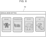
- the change in the transmission output torque (simulation torque) Tmtout may be prohibited by displaying the manual mode setting screen S2 instead of the change reception screen S1, graying the engine setting button B20, the transmission setting button B21, the sound setting button B22 and the set setting button B23 on the manual mode setting screen S2 as shown in FIG. 6 (hatching is provided in the figure), and making it impossible to select the buttons.
- the change reception screen S1 is displayed on the display 42, regardless of whether the battery electric vehicle 20 is traveling.
- the change reception screen S1 may be avoided from being displayed on the display 42, during the traveling.
- the display 42 is a touch panel type display device, and when the shift travel mode is selected, the occupant performs selection on the display 42, for the selection on the change reception screen S 1 or the manual mode setting screen S2 and for the change on the engine characteristic setting screen S3, the transmission characteristic setting screen, the sound setting screen or the simulated vehicle setting screen.
- the selection on the change reception screen S 1 or the manual mode setting screen S2 and the change on the engine characteristic setting screen S3, the transmission characteristic setting screen, the sound setting screen or the simulated vehicle setting screen may be performed through a portable terminal that is carried by the occupant and that can communicate with the ECU 50.
- the change in the transmission output torque (simulation torque) Tmtout may be prohibited during the traveling, by avoiding the reception of the instruction from the portable terminal.
- the change in the transmission output torque (simulation torque) Tmtout is permitted.
- the change in the transmission output torque (simulation torque) Tmtout may be permitted without considering whether the battery electric vehicle 20 is stopped, or, the change in the transmission output torque (simulation torque) Tmtout may be permitted based on only one of the case where the shift position SP is in the parking range and the case where the parking brake 27 is operated.
- the change in the transmission output torque (simulation torque) Tmtout may be permitted during the vehicle stop, regardless of whether the shift position SP is in the parking range or whether the parking brake 27 is operated.
- the shift position SP is changed by the operation of the shift lever 61 by the driver.
- the present invention can be applied also to a case where two paddle switches are disposed near a steering wheel and where the shift position SP is changed by performing upshift or downshift based on a paddle signal from the paddle switches.
- the motor 32 is an example of the "motor”
- the mode changeover switch 68 is an example of the "mode selection device”
- the ECU 50 is an example of the "control device”.
- the present invention can be utilized in the battery electric vehicle manufacturing industry.
Landscapes
- Engineering & Computer Science (AREA)
- Power Engineering (AREA)
- Transportation (AREA)
- Mechanical Engineering (AREA)
- Life Sciences & Earth Sciences (AREA)
- Sustainable Development (AREA)
- Sustainable Energy (AREA)
- Electric Propulsion And Braking For Vehicles (AREA)
Abstract
A battery electric vehicle (20) includes: a mode selection device (68) configured to select one travel mode from a plurality of travel modes by an operation of a driver, the plurality of travel modes including a motor travel mode in which a motor (32) is controlled such that required torque required for traveling of the battery electric vehicle (20) is output to a drive shaft (26), and a shift travel mode in which the motor (32) is controlled such that torque output to the drive shaft (26) based on a shift operation by the driver is simulation torque that simulates torque behavior in an engine vehicle equipped with an engine and a stepped transmission; and a control device (50) configured to control the motor (32) such that the battery electric vehicle (20) travels in the travel mode selected by the mode selection device (68). The control device (50) is configured to prohibit a change in the simulation torque while the battery electric vehicle (20) is traveling, when the shift travel mode is selected.
Description
- The present invention relates to a battery electric vehicle.
- Conventionally, as a battery electric vehicle of this type, there has been proposed a battery electric vehicle including a motor that outputs power to a drive shaft connected to an axle, and a mode selection device in which one travel mode is selected from a plurality of travel modes including a motor travel mode and a shift travel mode, by an operation of a driver (for example, see
Japanese Unexamined Patent Application Publication No. 2022-036845 JP 2022-036845 A - In the battery electric vehicle described above, the battery electric vehicle is able to travel simulating torque behavior in another engine vehicle, by changing the simulation torque, when the shift travel mode is selected. However, when the simulation torque is changed, the torque output to the drive shaft may fluctuate and behavior of the vehicle may change suddenly.
- A main object of a battery electric vehicle of the present invention is to suppress sudden changes in behavior of the vehicle.
- The battery electric vehicle according to the present invention employs the following means to achieve the above-described main object.
- A battery electric vehicle according to the present invention includes a motor configured to output torque to a drive shaft connected to an axle; a mode selection device configured to select one travel mode from a plurality of travel modes by an operation of a driver, the plurality of travel modes including a motor travel mode in which the motor is controlled such that required torque required for traveling of the battery electric vehicle is output to the drive shaft, and a shift travel mode in which the motor is controlled such that torque output to the drive shaft based on a shift operation by the driver is simulation torque that simulates torque behavior in an engine vehicle equipped with an engine and a stepped transmission; and a control device configured to control the motor such that the battery electric vehicle travels in the travel mode selected by the mode selection device. The control device is configured to prohibit a change in the simulation torque while the battery electric vehicle is traveling, when the shift travel mode is selected.
- In the battery electric vehicle according to the present invention, when the shift travel mode is selected, the change in the simulation torque is prohibited while the battery electric vehicle is traveling. When the simulation torque is changed, the torque output to the drive shaft may fluctuate. When such a torque fluctuation occurs while the vehicle is traveling, the behavior of the vehicle may change suddenly. However, by prohibiting changes in the simulation torque while the vehicle is traveling, it is possible to suppress sudden changes in the behavior of the vehicle.
- In such a battery electric vehicle according to the present invention, the control device may be configured to permit the change in the simulation torque in a case in which a shift position is in a parking range, when the shift travel mode is selected. The control device may be configured to permit the change in the simulation torque in a case in which a parking brake is operated, when the shift travel mode is selected. This allows the simulation torque to be changed while the vehicle is reliably stopped, so the simulation torque can be changed without suddenly changing the behavior of the vehicle.
- Moreover, the battery electric vehicle according to the present invention may further include a display device configured to display information. When the shift travel mode is selected, the control device may be configured to display, on the display device, a change reception screen for receiving an instruction to change the simulation torque, and prohibit reception on the change reception screen while the battery electric vehicle is traveling. As a result, since changes are not received while the vehicle is traveling, sudden changes in the behavior of the vehicle can be suppressed.
- Furthermore, the battery electric vehicle according to the present invention may further include a display device configured to display information. When the shift travel mode is selected, the control device may be configured to display, on the display device, a change reception screen for receiving an instruction to change the simulation torque while the battery electric vehicle is stopped, and not to display the change reception screen on the display device while the battery electric vehicle is traveling. In this way, since changes are not received while the vehicle is traveling, sudden changes in the behavior of the vehicle can be suppressed.
- Features, advantages, and technical and industrial significance of exemplary embodiments of the invention will be described below with reference to the accompanying drawings, in which like signs denote like elements, and wherein:
-
FIG. 1 is a configuration showing a schematic configuration of a battery electric vehicle as an embodiment of the present disclosure; -
FIG. 2 is a flowchart showing an example of a change permission-prohibition routine that is executed by an ECU; -
FIG. 3 is an explanatory diagram showing an example of a change reception screen that is displayed on a display; -
FIG. 4 is an explanatory diagram showing an example of a manual mode setting screen that is displayed on the display; -
FIG. 5 is an explanatory diagram showing an example of an engine characteristic setting screen that is displayed on the display; and -
FIG. 6 is an explanatory diagram showing an example of a manual mode setting screen that is displayed on the display during traveling in a shift travel mode. - Next, a mode for carrying out the present invention will be described with use of an embodiment.
-
FIG. 1 is a configuration showing a schematic configuration of a batteryelectric vehicle 20 as an embodiment of the present invention. As illustrated, the batteryelectric vehicle 20 in the embodiment includes amotor 32 for traveling, aninverter 34, abattery 36, adisplay 42, and an electronic control unit (referred to as an "ECU", hereinafter) 50. - The
motor 32 is configured as a three-phase alternating-current motor, and includes a rotor in which a permanent magnet is buried in a rotor core, and a stator in which a three-phase coil is wound around a stator core. The rotor of themotor 32 is joined to adrive shaft 26 that is connected todrive wheels differential gear 24. Aparking brake 27 is attached to thedrive shaft 26. - The
inverter 34 is used for the drive of themotor 32. Theinverter 34 is joined to thebattery 36 throughelectric power lines 38. Theinverter 34 includes six transistors T11 to T16 as switching elements and six diodes D11 to D16 that are respectively joined in parallel to the six transistors T11 to T16. The transistors T11 to T16 are disposed as pairs in each of which a positive electrode side line and a negative electrode side line of theelectric power lines 38 are respectively a source side and a sink side of two transistors. A joining point between the two transistors in each pair is joined to a coil in a corresponding phase (U-phase, V-phase, or W-phase) of themotor 32. Accordingly, when voltage is applied to theinverter 34, the proportion of the ON-time of each pair of the transistors T11 to T16 is adjusted by theECU 50, and thereby, a rotating magnetic field is formed in the three-phase coil, so that themotor 32 is driven and rotated. - The
battery 36 is configured as a lithium-ion secondary battery or a nickel-hydrogen secondary battery, and is joined to theinverter 34 through theelectric power lines 38. Acapacitor 39 for smoothing is attached to theelectric power lines 38. - The
display 42 is installed near a driver's seat. Thedisplay 42 is configured as a touch panel type display device that displays a variety of information in a visible manner. Thedisplay 42 is controlled by theECU 50. - The ECU 50 is equipped with a microcomputer that includes a CPU, a ROM, a RAM, a flash memory, and input and output ports. The
ECU 50 receives a rotational position θm of the rotor of themotor 32 from arotational position sensor 32a, phase currents Iu, Iv in the U-phase and V-phase of themotor 32 fromcurrent sensors battery 36 from avoltage sensor 36a, a current Ib of thebattery 36 from acurrent sensor 36b, and a voltage VL of the electric power lines 38 (the capacitor 39) from thevoltage sensor 39a. In addition, the ECU 50 receives a start signal from a start switch (ST) 60, a shift position SP that is the operation position of ashift lever 61 from ashift position sensor 62, an accelerator operation amount Acc that is the depression amount of anaccelerator pedal 63 from anaccelerator pedal sensor 64, and a brake pedal position BP that is the depression amount of abrake pedal 65 from abrake pedal sensor 66. In addition, the ECU 50 receives a vehicle velocity V from avehicle speed sensor 67, a switch signal from amode changeover switch 68, and a depression amount Da of a clutch pedal (pseudo clutch pedal) 70 from aclutch pedal sensor 71. Theshift lever 61 is configured to simulate a shift device included in a vehicle on which a manual transmission is mounted. Theshift lever 61 allows the selection of a plurality of shift ranges corresponding to variable speed levels of the manual transmission that is simulated, as the shift position SP. For example, theshift lever 61 allows the selection of one range from first to sixth ranges and a neutral range that are simulated. Each time themode changeover switch 68 is turned on, themode changeover switch 68 outputs a mode switching instruction for the switching between a motor travel mode and a shift travel mode. The motor travel mode and the shift travel mode will be described later. Aparking switch 69 is a switch for causing the shift position SP to be in a parking range. Each time theparking switch 69 is turned on, theparking switch 69 causes the shift position SP to be in the parking range or causes the shift position SP to be out of the parking range. Theclutch pedal 70 is configured to simulate a clutch pedal that is mounted on an engine vehicle that is simulated. Theclutch pedal 70 is configured such that the disposition and the operational feeling are the same as those of the clutch pedal of the vehicle on which the manual transmission is mounted. TheECU 50 outputs a control signal to themotor 32, a display signal to thedisplay 42, and the like. - In the battery
electric vehicle 20 in the embodiment, theECU 50 controls the motor 32 (the inverter 34) such that the traveling is performed in the motor travel mode or the shift travel mode. In the motor travel mode, the traveling is performed while themotor 32 outputs a required traveling torque Td* that is required for traveling. In the shift travel mode, the traveling is performed such that the behavior of the torque that is output from themotor 32 based on the operation of theshift lever 61 by a driver is the behavior of the torque in the engine vehicle equipped with an engine and the manual transmission as a stepped transmission. - In the motor travel mode, the required traveling torque Td* that is required for traveling (that is required for the drive shaft 26) is set as a torque command Tm* of the
motor 32, regardless of the shift position SP and the depression amount Da of theclutch pedal 70, and the transistors T11 to T16 of theinverter 34 are controlled such that themotor 32 is driven at the torque command Tm*. The required traveling torque Td* is set based on the accelerator operation amount Acc and the vehicle velocity V. In this way, themotor 32 is controlled such that the required traveling torque Td* that is required for traveling is output to thedrive shaft 26. Thereby, the traveling is performed while themotor 32 outputs the required traveling torque Td*. - In the shift travel mode, a virtual engine speed Ne as an engine speed in the engine vehicle that is simulated is set using a rotation speed Np of the drive shaft 26 (i.e., a rotation speed Nm of the motor 32), a gear ratio (transmission gear ratio) r corresponding to the shift position SP, and a slip-ratio (denoted by "slip") of the
clutch pedal 70 based on the depression amount Da of theclutch pedal 70, and, a virtual engine output torque Teout that is output from the engine of the engine vehicle that is simulated is set based on the accelerator operation amount Acc and the virtual engine speed Ne. Based on the slip-ratio, "slip", of theclutch pedal 70, a torque transmission gain k that is the transmissibility of the torque from the engine to the manual transmission is multiplied by the virtual engine output torque Teout, and thereby, a transmission input torque Tmtin is calculated. The torque transmission gain k is set so as to be smaller when the depression amount Da of theclutch pedal 70 is large, compared to when the depression amount Da of theclutch pedal 70 is small, and is set so as to be zero when the depression amount Da of theclutch pedal 70 is a maximal depression amount at which the torque transmission gain k between the engine and the manual transmission is zero. Then, the transmission input torque Tmtin is multiplied by the gear ratio (transmission gear ratio) r corresponding to the shift position SP, and thereby, the transmission output torque (simulation torque) Tmtout is calculated. The transmission output torque Tmtout is set as the torque command Tm* of themotor 32, and the transistors T11 to T16 of theinverter 34 are controlled such that themotor 32 is driven at the torque command Tm*. In this way, themotor 32 is controlled such that the torque that is output to thedrive shaft 26 based on the operation of theshift lever 61 by the driver is the transmission output torque (simulation torque) Tmtout that simulates the behavior of the torque in the engine vehicle equipped with the engine and the stepped transmission, and thereby the behavior of the torque that is output from themotor 32 based on the operation of theshift lever 61 by the driver can be the behavior of the torque in the engine vehicle equipped with the engine and the manual transmission. That is, it is possible to perform such a traveling that the engine vehicle equipped with the engine and the manual transmission is simulated, and it is possible to give an operational feeling that allows the driver to feel as if the driver was driving the engine vehicle equipped with the engine and the manual transmission. Further, in the shift travel mode, theECU 50 controls a speaker (not shown), such that the speaker outputs a sound (engine sound) that is of previously recorded engine sounds for respective engine speeds and that corresponds to the virtual engine speed Ne. This sound from the speaker gives an operational feeling that allows the driver to feel as if the driver was driving the engine vehicle equipped with the engine and the manual transmission. - Next, the operation of the battery
electric vehicle 20 in the embodiment configured as described above, particularly, the operation when the transmission output torque (simulation torque) Tmtout is changed in the shift travel mode will be described.FIG. 2 is a flowchart showing an example of a change permission-prohibition routine that is executed by theECU 50. The routine is executed every predetermined time (for example, every several milliseconds), when the shift travel mode is selected by themode changeover switch 68. - When the routine is executed, the CPU of the
ECU 50 executes a process of displaying a change reception screen S1 on the display 42 (S100).FIG. 3 is an explanatory diagram showing an example of the changereception screen S 1 that is displayed on thedisplay 42. The change reception screen S1 is a screen for receiving an instruction to change the transmission output torque (simulation torque) Tmtout from an occupant (the occupant includes a driver and a passenger of a vehicle). The changereception screen S 1 is displayed on thedisplay 42 when the shift travel mode is selected. On the changereception screen S 1, as shown inFIG. 3 , a plurality of buttons that can be selected by the occupant, as exemplified by a manual modesetting button B 1 is displayed. - Subsequently, the CPU of the
ECU 50 determines whether the vehicle is traveling (running) (S110). When the vehicle is not traveling, it is determined whether the shift position SP is set so as to be in the parking range by theparking switch 69 and whether theparking brake 27 is operated (S120). When the shift position SP is in the parking range or theparking brake 27 is operated, the CPU of theECU 50 permits the change in the transmission output torque (simulation torque) Tmtout (S130), and ends the routine. -
FIG. 4 is an explanatory diagram showing an example of a manual mode setting screen S2 that is displayed on thedisplay 42.FIG. 5 is an explanatory diagram showing an example of an engine characteristic setting screen S3 that is displayed on thedisplay 42. In the case where the change in the transmission output torque (simulation torque) Tmtout is permitted, theECU 50 displays the manual mode setting screen S2 shown inFIG. 4 , instead of the change reception screen S1, when the manual mode setting button B1 on the change reception screen S1 is selected by the occupant. An engine setting button B20 for setting the torque characteristic of the engine that is simulated in the shift travel mode, a transmission setting button B21 for setting the manual transmission that is simulated, a sound setting button B22 for selecting the engine sound that is simulated, and a set setting button B23 for selecting one vehicle type from a plurality of vehicle types equipped with the engine and the manual transmission are displayed on the manual mode setting screen S2. - When the engine setting button B20 is selected on the manual mode setting screen S2 by the occupant, the engine characteristic setting screen S3 shown in
FIG. 5 is displayed instead of the manual mode setting screen S2. A performance display screen S30 on which an engine performance curve showing a torque characteristic and an output characteristic while the abscissa axis indicates engine speed is displayed, and input buttons B30, B31, B32 for inputting the maximum output, maximum torque and maximum speed on the engine performance curve are displayed on the engine characteristic setting screen S3. When the maximum output, the maximum torque and the maximum speed are input through the input buttons B30, B31, B32, the engine performance curve that is displayed on the performance display screen S30 is changed depending on the input numerical values. In the shift travel mode, the engine performance curve that is displayed on the performance display screen S30 is adopted as the performance curve of the engine that is simulated, and the virtual engine output torque Teout that is output from the engine of the engine vehicle that is simulated is set based on the accelerator operation amount Acc and the virtual engine speed Ne. In this way, the torque characteristic of the engine of the engine vehicle that is simulated can be changed through the screen that is displayed on thedisplay 42. Thereby, the transmission output torque (simulation torque) Tmtout can be changed. - When the transmission setting button B21 is selected on the manual mode setting screen S2 by the occupant, a transmission characteristic setting screen (not shown) is displayed instead of the manual mode setting screen S2. A performance display screen on which a shift characteristic curve showing a drive power characteristic and a speed characteristic of the engine while the abscissa axis indicates vehicle velocity (vehicle speed), and an input button for inputting the transmission gear ratio at each variable speed level are displayed on the transmission characteristic setting screen. When the transmission gear ratio at the variable speed level is input through the input button, the transmission gear ratio at the variable speed level is changed to the input numerical values, and the shift characteristic curve is changed in accordance with the input numerical value. In the shift travel mode, the shift characteristic curve that is displayed on the performance display screen is adopted as the shift characteristic curve of the manual transmission that is simulated, and the transmission output torque (simulation torque) Tmtout is calculated. In this way, the characteristic of the transmission of the engine vehicle that is simulated can be changed through the screen that is displayed on the
display 42. Thereby, the transmission output torque (simulation torque) Tmtout can be changed. - When the sound setting button B22 is selected on the manual mode setting screen S2 by the occupant, a sound setting screen (not shown) is displayed instead of the manual mode setting screen S2. The sound volume of the engine sound can be changed on the sound setting screen.
- When the set setting button B23 is selected on the manual mode setting screen S2 by the occupant, a simulated vehicle setting screen (not shown) is displayed instead of the manual mode setting screen S2. The engine vehicle that is simulated in the shift travel mode can be changed from the present vehicle, on the simulated vehicle setting screen. Thereby, the transmission output torque (simulation torque) Tmtout can be changed.
- In this way, in the case where the vehicle is stopped in the shift travel mode and where the shift position SP is in the parking range or the
parking brake 27 is operated, the transmission output torque (simulation torque) Tmtout is permitted and the change on the changereception screen S 1 is received, so that the transmission output torque (simulation torque) Tmtout and the sound can be changed. When the shift position SP is in the parking range or when theparking brake 27 is operated, the batteryelectric vehicle 20 is reliably stopped, and therefore, the change can be performed without suddenly changing the behavior of the vehicle. - When the battery
electric vehicle 20 is traveling inS 110 or when the shift position SP is not in the parking range and theparking brake 27 is not operated inS 120 although the batteryelectric vehicle 20 is stopped inS 110, the change in the transmission output torque (simulation torque) Tmtout is prohibited (S140), and the routine ends. In this case, even when the manual mode setting button B1 is selected on the change reception screen S1 displayed on thedisplay 42, the display is not changed, and the display of the change reception screen S1 is maintained, so that the transmission output torque (simulation torque) Tmtout and the sound cannot be changed. In this way, when the vehicle is traveling in the shift travel mode, or when the shift position SP is not in the parking range and theparking brake 27 is not operated even during the vehicle stop, the change in the transmission output torque (simulation torque) Tmtout is prohibited and the change in the sound is prohibited. Thereby, it is possible to suppress sudden changes in the behavior of the vehicle when the vehicle is traveling or is not reliably stopped. - In the above-described battery
electric vehicle 20 in the embodiment, when the shift travel mode is selected, the change in the transmission output torque (simulation torque) Tmtout is prohibited during the traveling, and thereby, sudden changes in the behavior of the vehicle can be suppressed. - Further, in the battery
electric vehicle 20 in the embodiment, in the case where the shift travel mode is selected, where the batteryelectric vehicle 20 is stopped, and where the shift position SP is in the parking range or theparking brake 27 is operated, the change in the transmission output torque (simulation torque) Tmtout is permitted, and thereby, the transmission output torque (simulation torque) Tmtout can be changed without suddenly changing the behavior of the vehicle. - Furthermore, in the battery
electric vehicle 20 in the embodiment, when the shift travel mode is selected, the change reception screen S1 for receiving the instruction to change the transmission output torque (simulation torque) Tmtout is displayed on thedisplay 42, and the reception on the change reception screen S1 is prohibited during the traveling, and thereby, sudden changes in the behavior of the vehicle can be suppressed. - In the battery
electric vehicle 20 in the embodiment, when the shift travel mode is selected, the reception on the change reception screen S1 is prohibited during the traveling, and thereby, the change in the transmission output torque (simulation torque) Tmtout is prohibited. However, when the manual mode setting button B1 is selected on the change reception screen S1 displayed on thedisplay 42, the change in the transmission output torque (simulation torque) Tmtout may be prohibited by displaying the manual mode setting screen S2 instead of the change reception screen S1, graying the engine setting button B20, the transmission setting button B21, the sound setting button B22 and the set setting button B23 on the manual mode setting screen S2 as shown inFIG. 6 (hatching is provided in the figure), and making it impossible to select the buttons. - In the battery
electric vehicle 20 in the embodiment, when the shift travel mode is selected, the change reception screen S1 is displayed on thedisplay 42, regardless of whether the batteryelectric vehicle 20 is traveling. However, the change reception screen S1 may be avoided from being displayed on thedisplay 42, during the traveling. - In the battery
electric vehicle 20 in the embodiment, thedisplay 42 is a touch panel type display device, and when the shift travel mode is selected, the occupant performs selection on thedisplay 42, for the selection on the changereception screen S 1 or the manual mode setting screen S2 and for the change on the engine characteristic setting screen S3, the transmission characteristic setting screen, the sound setting screen or the simulated vehicle setting screen. However, the selection on the changereception screen S 1 or the manual mode setting screen S2 and the change on the engine characteristic setting screen S3, the transmission characteristic setting screen, the sound setting screen or the simulated vehicle setting screen may be performed through a portable terminal that is carried by the occupant and that can communicate with theECU 50. In this case, the change in the transmission output torque (simulation torque) Tmtout may be prohibited during the traveling, by avoiding the reception of the instruction from the portable terminal. - In the battery
electric vehicle 20 in the embodiment, in the case where the shift travel mode is selected, where the batteryelectric vehicle 20 is stopped, and where the shift position SP is in the parking range or theparking brake 27 is operated, the change in the transmission output torque (simulation torque) Tmtout is permitted. However, when the shift position SP is in the parking range or theparking brake 27 is operated, the change in the transmission output torque (simulation torque) Tmtout may be permitted without considering whether the batteryelectric vehicle 20 is stopped, or, the change in the transmission output torque (simulation torque) Tmtout may be permitted based on only one of the case where the shift position SP is in the parking range and the case where theparking brake 27 is operated. Alternatively, the change in the transmission output torque (simulation torque) Tmtout may be permitted during the vehicle stop, regardless of whether the shift position SP is in the parking range or whether theparking brake 27 is operated. - In the battery
electric vehicle 20 in the embodiment, the shift position SP is changed by the operation of theshift lever 61 by the driver. However, the present invention can be applied also to a case where two paddle switches are disposed near a steering wheel and where the shift position SP is changed by performing upshift or downshift based on a paddle signal from the paddle switches. - The correspondence relation between major elements of the embodiment and major elements of the present invention described in the summary of the invention will be described. In the embodiment, the
motor 32 is an example of the "motor", themode changeover switch 68 is an example of the "mode selection device", and theECU 50 is an example of the "control device". - The correspondence relation between major elements of the embodiment and major elements of the present invention described in the summary of the invention does not limit elements of the present invention described in the summary of the invention, because the embodiment is an example for specifically describing a mode for carrying out the present invention described in the summary of the invention. That is, the present invention described in the summary of the invention should be interpreted based on the description in the summary of the invention, and the embodiment is just a specific example of the present invention described in the summary of the invention.
- The mode for carrying out the present invention has been described above with use of the embodiment. The present invention is not limited to the embodiment at all, and naturally, can be carried out as various modes without departing from the spirit of the present invention.
- The present invention can be utilized in the battery electric vehicle manufacturing industry.
Claims (5)
- A battery electric vehicle (20) comprising:a motor (32) configured to output torque to a drive shaft (26) connected to an axle;a mode selection device (68) configured to select one travel mode from a plurality of travel modes by an operation of a driver, the plurality of travel modes including a motor travel mode in which the motor (32) is controlled such that required torque required for traveling of the battery electric vehicle (20) is output to the drive shaft (26), and a shift travel mode in which the motor (32) is controlled such that torque output to the drive shaft (26) based on a shift operation by the driver is simulation torque that simulates torque behavior in an engine vehicle equipped with an engine and a stepped transmission; anda control device (50) configured to control the motor (32) such that the battery electric vehicle (20) travels in the travel mode selected by the mode selection device (68),wherein the control device (50) is configured to prohibit a change in the simulation torque while the battery electric vehicle (20) is traveling, when the shift travel mode is selected.
- The battery electric vehicle (20) according to claim 1, wherein the control device (50) is configured to permit the change in the simulation torque in a case in which a shift position is in a parking range, when the shift travel mode is selected.
- The battery electric vehicle (20) according to claim 1, wherein the control device (50) is configured to permit the change in the simulation torque in a case in which a parking brake is operated, when the shift travel mode is selected.
- The battery electric vehicle (20) according to claim 1, further comprising a display device (42) configured to display information, wherein
when the shift travel mode is selected, the control device (50) is configured to display, on the display device (42), a change reception screen (S 1) for receiving an instruction to change the simulation torque, and prohibit reception on the change reception screen (S1) while the battery electric vehicle (20) is traveling. - The battery electric vehicle (20) according to claim 1, further comprising a display device (42) configured to display information, wherein
when the shift travel mode is selected, the control device (50) is configured to display, on the display device (42), a change reception screen (S1) for receiving an instruction to change the simulation torque while the battery electric vehicle (20) is stopped, and not to display the change reception screen (S1) on the display device (42) while the battery electric vehicle (20) is traveling.
Applications Claiming Priority (1)
| Application Number | Priority Date | Filing Date | Title |
|---|---|---|---|
| JP2023044466A JP7529078B1 (en) | 2023-03-20 | 2023-03-20 | Electric car |
Publications (1)
| Publication Number | Publication Date |
|---|---|
| EP4434798A1 true EP4434798A1 (en) | 2024-09-25 |
Family
ID=90368196
Family Applications (1)
| Application Number | Title | Priority Date | Filing Date |
|---|---|---|---|
| EP24164792.4A Pending EP4434798A1 (en) | 2023-03-20 | 2024-03-20 | Battery electric vehicle |
Country Status (4)
| Country | Link |
|---|---|
| US (1) | US20240317073A1 (en) |
| EP (1) | EP4434798A1 (en) |
| JP (2) | JP7529078B1 (en) |
| CN (1) | CN118665198A (en) |
Families Citing this family (2)
| Publication number | Priority date | Publication date | Assignee | Title |
|---|---|---|---|---|
| JP7529078B1 (en) * | 2023-03-20 | 2024-08-06 | トヨタ自動車株式会社 | Electric car |
| JP2025077825A (en) * | 2023-11-07 | 2025-05-19 | トヨタ自動車株式会社 | Electric Vehicles, Control Systems |
Citations (5)
| Publication number | Priority date | Publication date | Assignee | Title |
|---|---|---|---|---|
| US20220041064A1 (en) * | 2020-08-07 | 2022-02-10 | Toyota Jidosha Kabushiki Kaisha | Electric vehicle |
| US20220041066A1 (en) * | 2020-08-07 | 2022-02-10 | Toyota Jidosha Kabushiki Kaisha | Electric vehicle |
| JP2022036843A (en) * | 2020-08-24 | 2022-03-08 | トヨタ自動車株式会社 | Electric automobile |
| JP2022036845A (en) | 2020-08-24 | 2022-03-08 | トヨタ自動車株式会社 | Control device for electric vehicle |
| JP7225671B2 (en) * | 2018-10-22 | 2023-02-21 | スズキ株式会社 | electric vehicle |
Family Cites Families (6)
| Publication number | Priority date | Publication date | Assignee | Title |
|---|---|---|---|---|
| JP3748042B2 (en) | 2001-02-23 | 2006-02-22 | アイシン・エィ・ダブリュ株式会社 | Navigation device |
| JP4270165B2 (en) | 2005-05-09 | 2009-05-27 | トヨタ自動車株式会社 | Vehicle control device |
| JP2007017331A (en) * | 2005-07-08 | 2007-01-25 | Xanavi Informatics Corp | Navigation device |
| JP6221265B2 (en) | 2013-03-04 | 2017-11-01 | 株式会社デンソー | Touch panel operation device and operation event determination method in touch panel operation device |
| JP7415851B2 (en) | 2020-08-24 | 2024-01-17 | トヨタ自動車株式会社 | Electric car |
| JP7529078B1 (en) * | 2023-03-20 | 2024-08-06 | トヨタ自動車株式会社 | Electric car |
-
2023
- 2023-03-20 JP JP2023044466A patent/JP7529078B1/en active Active
-
2024
- 2024-01-15 CN CN202410058180.2A patent/CN118665198A/en active Pending
- 2024-02-01 US US18/429,989 patent/US20240317073A1/en active Pending
- 2024-03-15 JP JP2024041510A patent/JP7790456B2/en active Active
- 2024-03-20 EP EP24164792.4A patent/EP4434798A1/en active Pending
Patent Citations (5)
| Publication number | Priority date | Publication date | Assignee | Title |
|---|---|---|---|---|
| JP7225671B2 (en) * | 2018-10-22 | 2023-02-21 | スズキ株式会社 | electric vehicle |
| US20220041064A1 (en) * | 2020-08-07 | 2022-02-10 | Toyota Jidosha Kabushiki Kaisha | Electric vehicle |
| US20220041066A1 (en) * | 2020-08-07 | 2022-02-10 | Toyota Jidosha Kabushiki Kaisha | Electric vehicle |
| JP2022036843A (en) * | 2020-08-24 | 2022-03-08 | トヨタ自動車株式会社 | Electric automobile |
| JP2022036845A (en) | 2020-08-24 | 2022-03-08 | トヨタ自動車株式会社 | Control device for electric vehicle |
Also Published As
| Publication number | Publication date |
|---|---|
| JP2024134259A (en) | 2024-10-03 |
| US20240317073A1 (en) | 2024-09-26 |
| JP7790456B2 (en) | 2025-12-23 |
| CN118665198A (en) | 2024-09-20 |
| JP2024134538A (en) | 2024-10-03 |
| JP7529078B1 (en) | 2024-08-06 |
Similar Documents
| Publication | Publication Date | Title |
|---|---|---|
| EP4434798A1 (en) | Battery electric vehicle | |
| Mutoh et al. | Driving characteristics of an electric vehicle system with independently driven front and rear wheels | |
| CN101900618B (en) | System for displaying power flow in a hybrid vehicle | |
| JP2019022415A (en) | Control device | |
| EP4523948A1 (en) | Control system for electric vehicle with sound simulation | |
| EP4389498A1 (en) | Battery electric vehicle | |
| US12533963B2 (en) | Battery electric vehicle and control method of battery electric vehicle | |
| JP7428283B1 (en) | Electric car | |
| JP2021065038A (en) | vehicle | |
| US20250058646A1 (en) | Battery electric vehicle | |
| JP2005045864A (en) | Electric vehicle and control method thereof | |
| JP2025012138A (en) | Electric vehicle control device | |
| JP7416300B1 (en) | Electric car | |
| JP3409249B2 (en) | Hybrid vehicle | |
| JP2025042367A (en) | Drive unit | |
| JP7414173B1 (en) | Electric vehicle control device | |
| EP4556292A1 (en) | Battery electric vehicle | |
| US20250296451A1 (en) | Battery electric vehicle | |
| US20250214447A1 (en) | Battery electric vehicle and storage medium | |
| JP6750359B2 (en) | Automobile | |
| JP2025054707A (en) | Drive unit | |
| US20250262950A1 (en) | Electric vehicle | |
| US20250376044A1 (en) | Electric vehicle | |
| JP2017073926A (en) | Automobile | |
| EP4733122A1 (en) | Battery electric vehicle and non-transitory storage medium |
Legal Events
| Date | Code | Title | Description |
|---|---|---|---|
| PUAI | Public reference made under article 153(3) epc to a published international application that has entered the european phase |
Free format text: ORIGINAL CODE: 0009012 |
|
| STAA | Information on the status of an ep patent application or granted ep patent |
Free format text: STATUS: REQUEST FOR EXAMINATION WAS MADE |
|
| 17P | Request for examination filed |
Effective date: 20240331 |
|
| AK | Designated contracting states |
Kind code of ref document: A1 Designated state(s): AL AT BE BG CH CY CZ DE DK EE ES FI FR GB GR HR HU IE IS IT LI LT LU LV MC ME MK MT NL NO PL PT RO RS SE SI SK SM TR |