EP4434787A1 - Vehicular battery pack and related assembly method - Google Patents
Vehicular battery pack and related assembly method Download PDFInfo
- Publication number
- EP4434787A1 EP4434787A1 EP24164355.0A EP24164355A EP4434787A1 EP 4434787 A1 EP4434787 A1 EP 4434787A1 EP 24164355 A EP24164355 A EP 24164355A EP 4434787 A1 EP4434787 A1 EP 4434787A1
- Authority
- EP
- European Patent Office
- Prior art keywords
- floor
- battery pack
- cells
- electrochemical cells
- strips
- Prior art date
- Legal status (The legal status is an assumption and is not a legal conclusion. Google has not performed a legal analysis and makes no representation as to the accuracy of the status listed.)
- Granted
Links
Images


Classifications
-
- H—ELECTRICITY
- H01—ELECTRIC ELEMENTS
- H01M—PROCESSES OR MEANS, e.g. BATTERIES, FOR THE DIRECT CONVERSION OF CHEMICAL ENERGY INTO ELECTRICAL ENERGY
- H01M50/00—Constructional details or processes of manufacture of the non-active parts of electrochemical cells other than fuel cells, e.g. hybrid cells
- H01M50/20—Mountings; Secondary casings or frames; Racks, modules or packs; Suspension devices; Shock absorbers; Transport or carrying devices; Holders
- H01M50/289—Mountings; Secondary casings or frames; Racks, modules or packs; Suspension devices; Shock absorbers; Transport or carrying devices; Holders characterised by spacing elements or positioning means within frames, racks or packs
- H01M50/291—Mountings; Secondary casings or frames; Racks, modules or packs; Suspension devices; Shock absorbers; Transport or carrying devices; Holders characterised by spacing elements or positioning means within frames, racks or packs characterised by their shape
-
- B—PERFORMING OPERATIONS; TRANSPORTING
- B60—VEHICLES IN GENERAL
- B60K—ARRANGEMENT OR MOUNTING OF PROPULSION UNITS OR OF TRANSMISSIONS IN VEHICLES; ARRANGEMENT OR MOUNTING OF PLURAL DIVERSE PRIME-MOVERS IN VEHICLES; AUXILIARY DRIVES FOR VEHICLES; INSTRUMENTATION OR DASHBOARDS FOR VEHICLES; ARRANGEMENTS IN CONNECTION WITH COOLING, AIR INTAKE, GAS EXHAUST OR FUEL SUPPLY OF PROPULSION UNITS IN VEHICLES
- B60K1/00—Arrangement or mounting of electrical propulsion units
- B60K1/04—Arrangement or mounting of electrical propulsion units of the electric storage means for propulsion
-
- H—ELECTRICITY
- H01—ELECTRIC ELEMENTS
- H01M—PROCESSES OR MEANS, e.g. BATTERIES, FOR THE DIRECT CONVERSION OF CHEMICAL ENERGY INTO ELECTRICAL ENERGY
- H01M50/00—Constructional details or processes of manufacture of the non-active parts of electrochemical cells other than fuel cells, e.g. hybrid cells
- H01M50/20—Mountings; Secondary casings or frames; Racks, modules or packs; Suspension devices; Shock absorbers; Transport or carrying devices; Holders
- H01M50/204—Racks, modules or packs for multiple batteries or multiple cells
- H01M50/207—Racks, modules or packs for multiple batteries or multiple cells characterised by their shape
- H01M50/213—Racks, modules or packs for multiple batteries or multiple cells characterised by their shape adapted for cells having curved cross-section, e.g. round or elliptic
-
- H—ELECTRICITY
- H01—ELECTRIC ELEMENTS
- H01M—PROCESSES OR MEANS, e.g. BATTERIES, FOR THE DIRECT CONVERSION OF CHEMICAL ENERGY INTO ELECTRICAL ENERGY
- H01M50/00—Constructional details or processes of manufacture of the non-active parts of electrochemical cells other than fuel cells, e.g. hybrid cells
- H01M50/20—Mountings; Secondary casings or frames; Racks, modules or packs; Suspension devices; Shock absorbers; Transport or carrying devices; Holders
- H01M50/249—Mountings; Secondary casings or frames; Racks, modules or packs; Suspension devices; Shock absorbers; Transport or carrying devices; Holders specially adapted for aircraft or vehicles, e.g. cars or trains
-
- B—PERFORMING OPERATIONS; TRANSPORTING
- B60—VEHICLES IN GENERAL
- B60K—ARRANGEMENT OR MOUNTING OF PROPULSION UNITS OR OF TRANSMISSIONS IN VEHICLES; ARRANGEMENT OR MOUNTING OF PLURAL DIVERSE PRIME-MOVERS IN VEHICLES; AUXILIARY DRIVES FOR VEHICLES; INSTRUMENTATION OR DASHBOARDS FOR VEHICLES; ARRANGEMENTS IN CONNECTION WITH COOLING, AIR INTAKE, GAS EXHAUST OR FUEL SUPPLY OF PROPULSION UNITS IN VEHICLES
- B60K1/00—Arrangement or mounting of electrical propulsion units
- B60K1/04—Arrangement or mounting of electrical propulsion units of the electric storage means for propulsion
- B60K2001/0405—Arrangement or mounting of electrical propulsion units of the electric storage means for propulsion characterised by their position
- B60K2001/0416—Arrangement in the rear part of the vehicle
-
- B—PERFORMING OPERATIONS; TRANSPORTING
- B60—VEHICLES IN GENERAL
- B60K—ARRANGEMENT OR MOUNTING OF PROPULSION UNITS OR OF TRANSMISSIONS IN VEHICLES; ARRANGEMENT OR MOUNTING OF PLURAL DIVERSE PRIME-MOVERS IN VEHICLES; AUXILIARY DRIVES FOR VEHICLES; INSTRUMENTATION OR DASHBOARDS FOR VEHICLES; ARRANGEMENTS IN CONNECTION WITH COOLING, AIR INTAKE, GAS EXHAUST OR FUEL SUPPLY OF PROPULSION UNITS IN VEHICLES
- B60K1/00—Arrangement or mounting of electrical propulsion units
- B60K1/04—Arrangement or mounting of electrical propulsion units of the electric storage means for propulsion
- B60K2001/0405—Arrangement or mounting of electrical propulsion units of the electric storage means for propulsion characterised by their position
- B60K2001/0438—Arrangement under the floor
-
- B—PERFORMING OPERATIONS; TRANSPORTING
- B60—VEHICLES IN GENERAL
- B60L—PROPULSION OF ELECTRICALLY-PROPELLED VEHICLES; SUPPLYING ELECTRIC POWER FOR AUXILIARY EQUIPMENT OF ELECTRICALLY-PROPELLED VEHICLES; ELECTRODYNAMIC BRAKE SYSTEMS FOR VEHICLES IN GENERAL; MAGNETIC SUSPENSION OR LEVITATION FOR VEHICLES; MONITORING OPERATING VARIABLES OF ELECTRICALLY-PROPELLED VEHICLES; ELECTRIC SAFETY DEVICES FOR ELECTRICALLY-PROPELLED VEHICLES
- B60L50/00—Electric propulsion with power supplied within the vehicle
- B60L50/50—Electric propulsion with power supplied within the vehicle using propulsion power supplied by batteries or fuel cells
- B60L50/60—Electric propulsion with power supplied within the vehicle using propulsion power supplied by batteries or fuel cells using power supplied by batteries
- B60L50/64—Constructional details of batteries specially adapted for electric vehicles
-
- B—PERFORMING OPERATIONS; TRANSPORTING
- B60—VEHICLES IN GENERAL
- B60L—PROPULSION OF ELECTRICALLY-PROPELLED VEHICLES; SUPPLYING ELECTRIC POWER FOR AUXILIARY EQUIPMENT OF ELECTRICALLY-PROPELLED VEHICLES; ELECTRODYNAMIC BRAKE SYSTEMS FOR VEHICLES IN GENERAL; MAGNETIC SUSPENSION OR LEVITATION FOR VEHICLES; MONITORING OPERATING VARIABLES OF ELECTRICALLY-PROPELLED VEHICLES; ELECTRIC SAFETY DEVICES FOR ELECTRICALLY-PROPELLED VEHICLES
- B60L50/00—Electric propulsion with power supplied within the vehicle
- B60L50/50—Electric propulsion with power supplied within the vehicle using propulsion power supplied by batteries or fuel cells
- B60L50/60—Electric propulsion with power supplied within the vehicle using propulsion power supplied by batteries or fuel cells using power supplied by batteries
- B60L50/66—Arrangements of batteries
-
- H—ELECTRICITY
- H01—ELECTRIC ELEMENTS
- H01M—PROCESSES OR MEANS, e.g. BATTERIES, FOR THE DIRECT CONVERSION OF CHEMICAL ENERGY INTO ELECTRICAL ENERGY
- H01M2220/00—Batteries for particular applications
- H01M2220/20—Batteries in motive systems, e.g. vehicle, ship, plane
-
- H—ELECTRICITY
- H01—ELECTRIC ELEMENTS
- H01M—PROCESSES OR MEANS, e.g. BATTERIES, FOR THE DIRECT CONVERSION OF CHEMICAL ENERGY INTO ELECTRICAL ENERGY
- H01M50/00—Constructional details or processes of manufacture of the non-active parts of electrochemical cells other than fuel cells, e.g. hybrid cells
- H01M50/10—Primary casings; Jackets or wrappings
- H01M50/102—Primary casings; Jackets or wrappings characterised by their shape or physical structure
- H01M50/107—Primary casings; Jackets or wrappings characterised by their shape or physical structure having curved cross-section, e.g. round or elliptic
-
- Y—GENERAL TAGGING OF NEW TECHNOLOGICAL DEVELOPMENTS; GENERAL TAGGING OF CROSS-SECTIONAL TECHNOLOGIES SPANNING OVER SEVERAL SECTIONS OF THE IPC; TECHNICAL SUBJECTS COVERED BY FORMER USPC CROSS-REFERENCE ART COLLECTIONS [XRACs] AND DIGESTS
- Y02—TECHNOLOGIES OR APPLICATIONS FOR MITIGATION OR ADAPTATION AGAINST CLIMATE CHANGE
- Y02E—REDUCTION OF GREENHOUSE GAS [GHG] EMISSIONS, RELATED TO ENERGY GENERATION, TRANSMISSION OR DISTRIBUTION
- Y02E60/00—Enabling technologies; Technologies with a potential or indirect contribution to GHG emissions mitigation
- Y02E60/10—Energy storage using batteries
Definitions
- the present invention refers to the field of the energy storage systems in the automotive sector and relates to a vehicular battery pack and to a related assembly method.
- the present invention is advantageously, but not exclusively applied to battery packs for high-performance road vehicles, to which the following description will explicitly refer without thereby losing generality.
- Lithium batteries in relation to their high energy density increasingly allow the implementation of the electric power in the automotive sector.
- Lithium polymers in particular, currently represent, from the electrochemical point of view, the state of the art in the production of high-capacity batteries.
- Solutions are known which provide for the interconnection in series and in parallel of several cells (generally, each one of 3.7 V) for reaching the target total voltage and energy density for a vehicular battery pack.
- vehicular battery packs mainly comprising cylindrical or planar (prismatic or pocketed, so-called pouch) batteries.
- the batteries are generally anchored to the floor (floor pan) of the vehicle. In some cases, the batteries are housed in the same floor pan, in other cases, they are arranged in place of a traditional heat power train assembly.
- Patent document EP3674122 describes a battery pack in which the battery modules are made of a plurality of cylindrical batteries arranged parallel to each other and with their longitudinal axis (i.e. the axis of rotation around which the jelly-roll forming the cylindrical cell of each battery is formed) perpendicular to the floor pan.
- the battery modules usually available on the market often consist of planar pouch batteries, which have a very limited thickness with respect to the other dimensions.
- Two very wide opposite faces (through which the heat is almost integrally dissipated) are identified and four thin elongated sides are identified, wherein on one or on two opposite sides, the positive and negative terminals of the cell are arranged.
- the battery packs according to the prior art are configured to have the lower surface flat, and hence the batteries contained therein direct to the ground a flat surface (for example one of the main faces of the planar batteries or the base of the cylindrical batteries).
- road vehicles comprising a floor pan divided into two planar portions, a front one and a rear one, joined transversally, wherein the front portion is parallel to the ground and the rear portion determines a progressive moving away from the ground towards the rear of the road vehicle.
- the front planar portion and the rear planar portion are inclined with respect to each other by an angle less than 5°.
- the presence of such angle causes disadvantages from the aerodynamic point of view.
- the angle of the floor pan represents an unevenness which leads the fluid vein to detach from the bottom of the vehicle, thus reducing the rear aerodynamic load (contrary to what desired).
- the planarity of the floor pan is made necessary by the presence of the battery modules, which are usually provided with planar surfaces and, in order to prevent wasting large amounts of space, need a planar support.
- Document FR2868387A1 describes a moped having electric propulsion which operates utilizing a battery provided with a plurality of cylindrical cells.
- the object of the present invention is to provide a vehicular battery pack and a related assembly method, and a related vehicle which are at least partially exempt from the drawbacks described above and, simultaneously, are simple and cost-effective to fabricate.
- a vehicular battery pack and a related assembly method, and a related vehicle are provided according to what claimed in the following independent claims and, preferably, in any one of the claims directly or indirectly dependent on the independent claims.
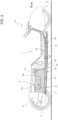
- reference numeral 1 indicates, as a whole, a road vehicle provided with two front wheels 2 and two rear wheels 3, of which at least one pair (or all) receive the torque from a power train 4.
- the road vehicle 1 is a vehicle having an at least partially electric propulsion (i.e. hybrid or completely electric).
- the power train 4 can be hybrid (i.e. comprises an internal combustion heat engine and at least one electric motor), or electric (i.e. comprises only one or more electric motors).
- second component does not imply the presence of a “first” component.
- Such terms in fact, are used as labels for improving the clarity and are not to be understood in a limiting manner.
- the road vehicle 1 further comprises a body 5 defining a passenger compartment 6, which is configured to accommodate at least one driver and possibly one or more passengers.
- the passenger compartment 6 defines at least one driving place 7 for the driver.
- the road vehicle 1 comprises a vehicular chassis 8, which supports the body 5.
- the road vehicle 1 comprises a vehicular battery pack 9 mounted on the chassis 8 and arranged so as to define at least part of a floor pan 10 of the road vehicle 1.
- the vehicular battery pack 9 comprises a support structure 11 extending along the vehicular longitudinal axis X and comprising a floor 12, which defines, at least in part, the floor pan of the road vehicle 1.
- the floor 12 substantially extends between a front axle (of known type and not illustrated) and a rear axle (also of known type and not illustrated) of the road vehicle 1.
- the floor 12 has a board-like conformation (i.e. plate-like, with the thickness remarkably less than the other two dimensions) comprising an inner surface 13 and an outer surface 14, opposite the inner surface 13 and configured to be externally exposed so as to face the ground G.
- a board-like conformation i.e. plate-like, with the thickness remarkably less than the other two dimensions
- the support structure 11 defines within it a housing 15, which is limited inferiorly by the floor 12.
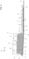
- the battery pack 9 further comprises cylindrical electrochemical cells 16, electrically connected to each other and arranged internally on the inner surface 13 of the housing 15.
- each of the cylindrical electrochemical cells 16 comprises a lateral surface 17 having a circular cross-section extending along an axis A of symmetry and two planar bases 18, which are crossed by said axis A of symmetry.
- the cylindrical electrochemical cells 16 are of known type, for example of the lithium ion type, and will not be further specifically described in the following, since they are made with known methodologies.
- the floor 12 of the support structure 11 has an at least partially curved conformation, which deflects distancing itself from the ground G along the longitudinal axis X in a direction opposite the normal travel direction D of the road vehicle 1.
- an aerodynamic downforce is generated which enables increasing the rear load of the road vehicle 1.
- the at least partially curved conformation enables leaving the fluid vein adherent to the floor 12 without detachments (unlike what occurs with the prior art angled structures). This leads to a decrease in the aerodynamic drag of the floor 12 and thus to an increase in the lift-to-drag ratio (given, as is known, by the ratio of load to drag).
- the cylindrical electrochemical cells 16 are (at least in part) arranged side by side and with the respective axes A of symmetry parallel to each other (in particular horizontal).
- the electrochemical cells 16 are arranged with the respective lateral surface 17 in contact with the inner surface 13 of the floor 12, so as to form one or more strips 19 of electrochemical cells parallel both to each other, and to the curved conformation, i.e. to the profile, of the floor 12 of the support structure 11, i.e. of the inner surface 13.
- the floor 12 has a constant thickness.
- the floor 12 comprises, along the longitudinal axis X, a front portion 20 substantially parallel to the ground G and a rear portion 21 diverging from the ground G, both planar, which are connected by a curved portion 22.
- the one or more strips 19 of parallel electrochemical cells extend from the front portion 20 to the rear portion 21, and have at least the lateral surface 17 of one electrochemical cell 16 in contact with the curved portion 22.
- the axes A of the electrochemical cells 16 arranged in contact with the inner surface 13, if interpolated, form an approximation of a plane parallel to the floor 12 (at a distance, obviously, equal to the radius of the planar bases 18, which are circular).
- the quantity of cells 16 resting on the floor 12 is maximized, without the wastes of space which instead there would be with cells 16 arranged vertically, as is known.
- the curved portion 22 enables advantages of aerodynamic type, reducing some turbulent motions under the road vehicle 1.
- the battery pack 9 comprises a plurality of strips 19 of cells 16 parallel to each other, which form a first layer 23 covering at least for the most part the available inner surface 13 of the floor 12 (some portions of the floor 12 could be occupied by structural elements such as side members and/or cross members of known type).
- a strip 19 is illustrated in cross-section which extends seamlessly for at least 70% of the length of the floor 12.
- the battery pack 9 comprises further layers 24 of strips 19 of electrochemical cells 16 at least partially overlapping the first layer 23.
- the cells of the further layers 24 are arranged so as to form a quincunx formation with the cylindrical cells 16 of the first layer 23.
- the cells 16 of the further layers 24 overlap in a staggered manner (by half a cell 16) with respect to the lower layer. In such manner, the quantity of cylindrical cells 16 is maximized, the volume being equal.
- the battery pack 9 comprises a verticalized portion 25, supported by the rear portion 21 and having a thickness W' greater than the rest of the battery pack 9.
- the verticalized portion 25 comprises at least three, in particular at least five further overlapping layers 24.
- the verticalized portion 25 comprises a parallelepiped case 26, which protrudes from the rest of the battery pack 9.
- the verticality of the verticalized portion 25 enables remarkably expanding the capacity of the battery pack 9.
- the battery pack 9 further comprises a lowered portion 27, supported by the front portion 20 and having a thickness W" less than the verticalized portion 25.
- the cells 16 of a first strip 19 of the plurality of strips have length L', along the longitudinal axis, different from a length L" of the cells 16 of a second strip 19 of the plurality of strips 19, as is illustrated in the non-limiting embodiment of Figure 4 .
- the cylindrical cells 16 of a same strip 19 have different lengths L', L", as is illustrated in the non-limiting embodiment of Figure 4 .
- the cylindrical cells 16 having different lengths L', L" are arranged to have, each, one of the two planar bases 18 of each of the cells on a same feed plane ZX. In such manner, it will be simpler to connect to each other at least the terminals of the cells 16 on the same plane ZX.
- the battery pack 9 also comprises cylindrical cells 16 with vertical axis A of symmetry, orthogonal to the inner surface 13.
- the battery pack 9, in a plan view, as the one schematically illustrated in Figure 4 comprises a central rectangular zone 28 filled by means of cells 16 arranged horizontally and a peripheral amorphous zone 29 filled with cells 16 arranged vertically, so as to be able to anyway vertically arrange the lateral surface 17 of the cells 16 (illustrated at the bottom in Figure 4 ) in contact with the curved geometry of the sides 30 of the battery pack 9.
- the battery pack 9 is arranged inferiorly the passenger compartment 6.
- the front portion 20 is arranged under the driving place 7 and the possible passenger place next to it, whereas the rear portion 21 is arranged behind the seats contained inside the passenger compartment 6.
- the battery pack 9 is suitable for being connected to the power train 4 of the vehicle 1 having an at least partially electric propulsion and is adapted to accumulate the electric energy produced by an electric machine (not illustrated).
- the battery pack 9 is connected to the electric machine by means of the interposition of an electric energy converter (commonly known as inverter) which, on the basis of the different needs of the electric machine and of the battery pack 9 transforms the direct current exiting the battery pack 9 into alternating current for the electric machine, and vice versa.
- an electric energy converter commonly known as inverter
- the battery pack 9 comprises at least one section configured to house a battery control and monitoring system (normally called BMS - "Battery Management System"), adapted to control the operation parameters of the electrochemical cells 16.
- BMS Battery Management System
- the ends of the cells C contained in the battery pack 16 are connected to terminals by means of a BUS connection of known type.
- a method of assembling a vehicular battery pack 9 comprises the steps of:
- the electrochemical cells 16 are arranged with the respective lateral surface 17 in contact with the inner surface 13 of the floor 12, so as to form the one or more strips 19 of electrochemical cells 16 parallel to each other and to the at least partially curved conformation of the floor 12 of the support structure 11.
- the electrochemical cells 16 are arranged so as to form a first layer 23 covering at least for the most part the available inner surface 13 of the floor 12.
- the method comprises the further step of arranging the further layers 24 of strips 19 of electrochemical cells 16 at least partially overlapping the first layer 23, in which the cells 16 of the further layers 24 are arranged so as to form the quincunx formation with the cylindrical cells 16 of the first layer.
- the verticalized portion 25 is formed, supported by the rear portion 21 and having the thickness W' greater than the rest of the battery pack 9.
- the verticalized portion 25 at least three, in particular at least five, further overlapping layers 24 are arranged.
- the present invention has many advantages.
- the present invention allows improving the lift-to-drag ratio preventing angles on the floor pan which degrade the vehicular aerodynamics making the fluid vein detach.
- a further advantage of the present invention lies in the simplicity of the mounting of the battery pack.
- the present invention allows overcoming the geometrical limits currently present in the prior art battery packs, freeing the designers from the concept of a flat vehicular bottom.
Landscapes
- Chemical & Material Sciences (AREA)
- Engineering & Computer Science (AREA)
- Chemical Kinetics & Catalysis (AREA)
- Electrochemistry (AREA)
- General Chemical & Material Sciences (AREA)
- Combustion & Propulsion (AREA)
- Transportation (AREA)
- Mechanical Engineering (AREA)
- Aviation & Aerospace Engineering (AREA)
- Battery Mounting, Suspending (AREA)
- Inorganic Chemistry (AREA)
Abstract
Description
- This patent application claims priority from
Italian patent application no. 102023000005253 filed on March 21, 2023 - The present invention refers to the field of the energy storage systems in the automotive sector and relates to a vehicular battery pack and to a related assembly method.
- In particular, the present invention is advantageously, but not exclusively applied to battery packs for high-performance road vehicles, to which the following description will explicitly refer without thereby losing generality.
- Lithium batteries in relation to their high energy density increasingly allow the implementation of the electric power in the automotive sector. Lithium polymers, in particular, currently represent, from the electrochemical point of view, the state of the art in the production of high-capacity batteries.
- Solutions are known which provide for the interconnection in series and in parallel of several cells (generally, each one of 3.7 V) for reaching the target total voltage and energy density for a vehicular battery pack.
- Various types of vehicular battery packs are known mainly comprising cylindrical or planar (prismatic or pocketed, so-called pouch) batteries.
- The batteries are generally anchored to the floor (floor pan) of the vehicle. In some cases, the batteries are housed in the same floor pan, in other cases, they are arranged in place of a traditional heat power train assembly.
- Patent document
EP3674122 describes a battery pack in which the battery modules are made of a plurality of cylindrical batteries arranged parallel to each other and with their longitudinal axis (i.e. the axis of rotation around which the jelly-roll forming the cylindrical cell of each battery is formed) perpendicular to the floor pan. - Alternatively, the battery modules usually available on the market (not only the automotive market, but also the consumer electronics market) often consist of planar pouch batteries, which have a very limited thickness with respect to the other dimensions. Two very wide opposite faces (through which the heat is almost integrally dissipated) are identified and four thin elongated sides are identified, wherein on one or on two opposite sides, the positive and negative terminals of the cell are arranged.
- In any case, the battery packs according to the prior art are configured to have the lower surface flat, and hence the batteries contained therein direct to the ground a flat surface (for example one of the main faces of the planar batteries or the base of the cylindrical batteries).
- For high-performance vehicles, it is preferable to have a conformation of the lower part of the chassis of the vehicle such to satisfy predetermined mechanical and aerodynamic requirements.
- In accordance with what described by European patent
EP3674122 , road vehicles are known comprising a floor pan divided into two planar portions, a front one and a rear one, joined transversally, wherein the front portion is parallel to the ground and the rear portion determines a progressive moving away from the ground towards the rear of the road vehicle. In particular, the front planar portion and the rear planar portion are inclined with respect to each other by an angle less than 5°. - However, the presence of such angle causes disadvantages from the aerodynamic point of view. In particular, the angle of the floor pan represents an unevenness which leads the fluid vein to detach from the bottom of the vehicle, thus reducing the rear aerodynamic load (contrary to what desired).
- Simultaneously, though, the planarity of the floor pan is made necessary by the presence of the battery modules, which are usually provided with planar surfaces and, in order to prevent wasting large amounts of space, need a planar support.
- The need is thus felt to optimize the aerodynamics of the road vehicle without wasting useful space for the batteries.
- Document
FR2868387A1 - Document
US2020207201A1 describes an electric or hybrid sports car which comprises a battery pack which incorporates at least one structural element of the chassis of the vehicle, wherein such structural element can be removed from the chassis of the vehicle only together with the battery pack. - The object of the present invention is to provide a vehicular battery pack and a related assembly method, and a related vehicle which are at least partially exempt from the drawbacks described above and, simultaneously, are simple and cost-effective to fabricate.
- According to the present invention, a vehicular battery pack and a related assembly method, and a related vehicle are provided according to what claimed in the following independent claims and, preferably, in any one of the claims directly or indirectly dependent on the independent claims.
- The claims describe preferred embodiments of the present invention forming integral part of the present description.
- The present invention will now be described with reference to the accompanying drawings, which illustrate some non-limiting example embodiments thereof, wherein:
-
Figure 1 is a schematic perspective view of a vehicle having an at least partially electric propulsion comprising a battery pack in accordance with the present invention; -
Figure 2 is a schematic side view of part of the vehicle ofFigure 1 ; -
Figure 3 is a schematic side section view of the battery pack of the vehicle ofFigures 1 and2 ; -
Figure 4 is a schematic plan view of the battery pack ofFigure 3 . - In
Figure 1 , reference numeral 1 indicates, as a whole, a road vehicle provided with twofront wheels 2 and tworear wheels 3, of which at least one pair (or all) receive the torque from apower train 4. - The road vehicle 1 is a vehicle having an at least partially electric propulsion (i.e. hybrid or completely electric). In other words, the
power train 4 can be hybrid (i.e. comprises an internal combustion heat engine and at least one electric motor), or electric (i.e. comprises only one or more electric motors). - The same reference numerals and letters in the figures identify the same elements or components with the same function.
- Within the scope of the present description the term "second" component does not imply the presence of a "first" component. Such terms, in fact, are used as labels for improving the clarity and are not to be understood in a limiting manner.
- The elements and the characteristics illustrated in the various preferred embodiments, including the drawings, can be combined with one another without thereby departing from the scope of protection of the present application as described in the following.
- The road vehicle 1 further comprises a
body 5 defining apassenger compartment 6, which is configured to accommodate at least one driver and possibly one or more passengers. Thepassenger compartment 6 defines at least onedriving place 7 for the driver. - It is specified that in the following of the present description, expressions such as "at the top", "inferiorly", "at the front", "at the rear" and the like are utilized with reference to normal travel conditions of the road vehicle 1 along the normal travel direction D.
- As is illustrated in the non-limiting embodiment of
Figure 1 , it is further possible to define: - a longitudinal axis X, integral with the vehicle 1 and arranged, in use, horizontal and parallel to a normal travel direction D of the vehicle 1;
- a transversal axis Y, integral with the vehicle 1 and arranged, in use, horizontal and orthogonal to the axis X; and
- a vertical axis Z, integral with the vehicle 1 and arranged, in use, vertical and orthogonal to the axes X, Y.
- The road vehicle 1 comprises a
vehicular chassis 8, which supports thebody 5. - Furthermore, the road vehicle 1 comprises a
vehicular battery pack 9 mounted on thechassis 8 and arranged so as to define at least part of afloor pan 10 of the road vehicle 1. - In the non-limiting embodiments of the accompanying figures, the
vehicular battery pack 9 comprises asupport structure 11 extending along the vehicular longitudinal axis X and comprising afloor 12, which defines, at least in part, the floor pan of the road vehicle 1. - Advantageously but not limitedly, the
floor 12 substantially extends between a front axle (of known type and not illustrated) and a rear axle (also of known type and not illustrated) of the road vehicle 1. - As is illustrated in the non-limiting embodiments of
Figures 2 and3 , thefloor 12 has a board-like conformation (i.e. plate-like, with the thickness remarkably less than the other two dimensions) comprising aninner surface 13 and anouter surface 14, opposite theinner surface 13 and configured to be externally exposed so as to face the ground G. - In particular, the
support structure 11 defines within it ahousing 15, which is limited inferiorly by thefloor 12. - The
battery pack 9 further comprises cylindricalelectrochemical cells 16, electrically connected to each other and arranged internally on theinner surface 13 of thehousing 15. - Specifically, as is highlighted by
Figures 3 and4 , each of the cylindricalelectrochemical cells 16 comprises alateral surface 17 having a circular cross-section extending along an axis A of symmetry and twoplanar bases 18, which are crossed by said axis A of symmetry. - The cylindrical
electrochemical cells 16 are of known type, for example of the lithium ion type, and will not be further specifically described in the following, since they are made with known methodologies. - Advantageously, the
floor 12 of thesupport structure 11 has an at least partially curved conformation, which deflects distancing itself from the ground G along the longitudinal axis X in a direction opposite the normal travel direction D of the road vehicle 1. In such manner, an aerodynamic downforce is generated which enables increasing the rear load of the road vehicle 1. Specifically, the at least partially curved conformation enables leaving the fluid vein adherent to thefloor 12 without detachments (unlike what occurs with the prior art angled structures). This leads to a decrease in the aerodynamic drag of thefloor 12 and thus to an increase in the lift-to-drag ratio (given, as is known, by the ratio of load to drag). - Advantageously, in order to optimize the use of the space despite the curved geometry of the
floor 12 of thebattery pack 9, the cylindricalelectrochemical cells 16 are (at least in part) arranged side by side and with the respective axes A of symmetry parallel to each other (in particular horizontal). - Advantageously, the
electrochemical cells 16 are arranged with the respectivelateral surface 17 in contact with theinner surface 13 of thefloor 12, so as to form one ormore strips 19 of electrochemical cells parallel both to each other, and to the curved conformation, i.e. to the profile, of thefloor 12 of thesupport structure 11, i.e. of theinner surface 13. - In particular, not limitedly, the
floor 12 has a constant thickness. - In the non-limiting embodiment of
Figures 2 and3 , thefloor 12 comprises, along the longitudinal axis X, afront portion 20 substantially parallel to the ground G and arear portion 21 diverging from the ground G, both planar, which are connected by acurved portion 22. - Advantageously but not necessarily, the one or
more strips 19 of parallel electrochemical cells extend from thefront portion 20 to therear portion 21, and have at least thelateral surface 17 of oneelectrochemical cell 16 in contact with thecurved portion 22. In other words, the axes A of theelectrochemical cells 16 arranged in contact with theinner surface 13, if interpolated, form an approximation of a plane parallel to the floor 12 (at a distance, obviously, equal to the radius of theplanar bases 18, which are circular). In such manner, despite thecurved portion 22 of thefloor 12, the quantity ofcells 16 resting on thefloor 12 is maximized, without the wastes of space which instead there would be withcells 16 arranged vertically, as is known. In particular, thecurved portion 22 enables advantages of aerodynamic type, reducing some turbulent motions under the road vehicle 1. - Preferably but not limitedly, the
battery pack 9 comprises a plurality ofstrips 19 ofcells 16 parallel to each other, which form afirst layer 23 covering at least for the most part the availableinner surface 13 of the floor 12 (some portions of thefloor 12 could be occupied by structural elements such as side members and/or cross members of known type). - In the non-limiting embodiment of
Figure 3 astrip 19 is illustrated in cross-section which extends seamlessly for at least 70% of the length of thefloor 12. - According to some preferred but non-limiting embodiments, such as the one illustrated in
Figures 2 and3 , thebattery pack 9 comprisesfurther layers 24 ofstrips 19 ofelectrochemical cells 16 at least partially overlapping thefirst layer 23. In particular, the cells of thefurther layers 24 are arranged so as to form a quincunx formation with thecylindrical cells 16 of thefirst layer 23. In other words, thecells 16 of thefurther layers 24 overlap in a staggered manner (by half a cell 16) with respect to the lower layer. In such manner, the quantity ofcylindrical cells 16 is maximized, the volume being equal. - Preferably, and as is illustrated in the non-limiting embodiment of
Figure 3 , thebattery pack 9 comprises averticalized portion 25, supported by therear portion 21 and having a thickness W' greater than the rest of thebattery pack 9. In particular, theverticalized portion 25 comprises at least three, in particular at least five further overlapping layers 24. - In the embodiment of
Figure 3 , theverticalized portion 25 comprises aparallelepiped case 26, which protrudes from the rest of thebattery pack 9. In particular, theparallelepiped case 26, due to the inclination with respect to the ground G of therear portion 21, has a parallelogram cross-section along the plane ZX (i.e. the plane on which the axes Z and X lie), whereas it has a rectangular cross-section on the plane ZY (i.e. the plane on which the axes Z and Y lie). The verticality of theverticalized portion 25 enables remarkably expanding the capacity of thebattery pack 9. - Advantageously but not necessarily, the
battery pack 9 further comprises a loweredportion 27, supported by thefront portion 20 and having a thickness W" less than theverticalized portion 25. - In particular, in the lowered
portion 27 only thefirst layer 23 ofstrips 19 ofcells 16 is present. Alternatively, in the loweredportion 27 only thefirst layer 23 ofstrips 19 ofcells 16 and a singlefurther layer 24 overlapping it are present. - In order to optimize the spaces, given the inferiorly and laterally curved geometry of the
battery pack 9, various embodiments are possible. - In some non-limiting cases, the
cells 16 of afirst strip 19 of the plurality of strips have length L', along the longitudinal axis, different from a length L" of thecells 16 of asecond strip 19 of the plurality ofstrips 19, as is illustrated in the non-limiting embodiment ofFigure 4 . - Alternatively or additionally, the
cylindrical cells 16 of asame strip 19 have different lengths L', L", as is illustrated in the non-limiting embodiment ofFigure 4 . In particular, thecylindrical cells 16 having different lengths L', L" are arranged to have, each, one of the twoplanar bases 18 of each of the cells on a same feed plane ZX. In such manner, it will be simpler to connect to each other at least the terminals of thecells 16 on the same plane ZX. - In further non-limiting cases, as is partially schematically illustrated in
Figure 4 , thebattery pack 9 also comprisescylindrical cells 16 with vertical axis A of symmetry, orthogonal to theinner surface 13. In particular, thebattery pack 9, in a plan view, as the one schematically illustrated inFigure 4 , comprises a centralrectangular zone 28 filled by means ofcells 16 arranged horizontally and a peripheralamorphous zone 29 filled withcells 16 arranged vertically, so as to be able to anyway vertically arrange thelateral surface 17 of the cells 16 (illustrated at the bottom inFigure 4 ) in contact with the curved geometry of thesides 30 of thebattery pack 9. - In particular, the
battery pack 9 is arranged inferiorly thepassenger compartment 6. In particular, thefront portion 20 is arranged under the drivingplace 7 and the possible passenger place next to it, whereas therear portion 21 is arranged behind the seats contained inside thepassenger compartment 6. - In particular, the
battery pack 9 is suitable for being connected to thepower train 4 of the vehicle 1 having an at least partially electric propulsion and is adapted to accumulate the electric energy produced by an electric machine (not illustrated). Thebattery pack 9 is connected to the electric machine by means of the interposition of an electric energy converter (commonly known as inverter) which, on the basis of the different needs of the electric machine and of thebattery pack 9 transforms the direct current exiting thebattery pack 9 into alternating current for the electric machine, and vice versa. - The
battery pack 9 comprises at least one section configured to house a battery control and monitoring system (normally called BMS - "Battery Management System"), adapted to control the operation parameters of theelectrochemical cells 16. The ends of the cells C contained in thebattery pack 16 are connected to terminals by means of a BUS connection of known type. - According to a further aspect of the present invention, a method of assembling a
vehicular battery pack 9 is provided. The method comprises the steps of: - fabricating in metal plate or composite material the
support structure 11 extending along the vehicular longitudinal axis X and comprising thefloor 12 configured to define, at least in part, thefloor pan 10 of the road vehicle 1; - arranging the cylindrical
electrochemical cells 16, electrically connected to each other, inside thehousing 15, in correspondence with theinner surface 13. - In particular, during the arranging step, the
electrochemical cells 16 are arranged with the respectivelateral surface 17 in contact with theinner surface 13 of thefloor 12, so as to form the one ormore strips 19 ofelectrochemical cells 16 parallel to each other and to the at least partially curved conformation of thefloor 12 of thesupport structure 11. - Preferably, the
electrochemical cells 16 are arranged so as to form afirst layer 23 covering at least for the most part the availableinner surface 13 of thefloor 12. - Preferably but not limitedly, the method comprises the further step of arranging the
further layers 24 ofstrips 19 ofelectrochemical cells 16 at least partially overlapping thefirst layer 23, in which thecells 16 of thefurther layers 24 are arranged so as to form the quincunx formation with thecylindrical cells 16 of the first layer. - Advantageously but not limitedly, during the further arranging step, the
verticalized portion 25 is formed, supported by therear portion 21 and having the thickness W' greater than the rest of thebattery pack 9. In particular, in theverticalized portion 25, at least three, in particular at least five, further overlappinglayers 24 are arranged. - Although the invention described above particularly refers to some very precise example embodiments, it is not to be considered limited to such example embodiments, falling within its scope all the variations, modifications or simplifications covered by the appended claims, such as for example a different shape of the battery pack, a different placing thereof, a different type of materials, etc.
- The present invention has many advantages.
- Firstly, it allows having sinuous shapes on the bottom of the battery pack on which to rest the lateral surfaces of the cylindrical cells.
- Furthermore, the present invention allows improving the lift-to-drag ratio preventing angles on the floor pan which degrade the vehicular aerodynamics making the fluid vein detach.
- A further advantage of the present invention lies in the simplicity of the mounting of the battery pack.
- Finally, the present invention allows overcoming the geometrical limits currently present in the prior art battery packs, freeing the designers from the concept of a flat vehicular bottom.
-
- 1
- vehicle
- 2
- wheels
- 3
- wheels
- 4
- power train
- 5
- body
- 6
- passenger compartment
- 7
- driving place
- 8
- chassis
- 9
- battery pack
- 10
- floor pan
- 11
- support structure
- 12
- floor
- 13
- inner surface
- 14
- outer surface
- 15
- housing
- 16
- electrochemical cells
- 17
- lateral surface
- 18
- planar bases
- 19
- strips of cells
- 20
- front portion
- 21
- rear portion
- 22
- curved portion
- 23
- first layer
- 24
- further layers
- 25
- verticalized portion
- 26
- parallelepiped case
- 27
- lowered portion
- 28
- rectangular zone
- 29
- amorphous zone
- 30
- sides of the battery pack
- A
- axis of symmetry
- D
- direction
- G
- ground
- L'
- length
- L"
- length
- W'
-
thickness 25 - W"
-
thickness 27 - X
- axis
- Y
- axis
- Z
- axis
Claims (13)
- A vehicular battery pack (9) comprising:- a support structure (11) extending along a vehicular longitudinal axis (X) and comprising a floor (12) configured to define, at least in part, a floor pan (10) of a road vehicle (1); the floor (12) having a board-like conformation comprising an inner surface (13) and an outer surface (14), opposite the inner surface (13) and configured to be externally exposed so as to face the ground (G); the support structure (11) defining within it a housing (15) limited inferiorly by said floor (12);- cylindrical electrochemical cells (16), electrically connected to each other and arranged internally on the inner surface of said housing; each of the cylindrical electrochemical cells (16) comprises a lateral surface (17) having a circular cross-section extending along an axis (A) of symmetry and two planar bases (18), which are crossed by said axis (A) of symmetry;the vehicular battery pack (9) being characterised in that the floor (12) of the support structure (11) has an at least partially curved conformation, which deflects distancing itself from the ground (G) along the longitudinal axis (X) in a direction opposite a normal travel direction (D) of the road vehicle (1);wherein said cylindrical electrochemical cells (16) are at least partially arranged side by side and with their respective axes of symmetry parallel to each other;wherein said electrochemical cells (16) are arranged with said respective lateral surface (17) in contact with the inner surface (13) of the floor (12), so as to form one or more strips (19) of electrochemical cells (16) parallel to each other and to the at least partially curved conformation of the floor (12) of the support structure (11);wherein the floor (12) comprises, along the longitudinal axis (X), a front portion (20) substantially parallel to the ground (G) and a rear portion (21) diverging from the ground (G), both planar, which are connected by a curved portion (22); the one or more strips (19) of parallel electrochemical cells (16) extending from the front portion (20) to the rear portion (21), and having at least the lateral surface (17) of one electrochemical cell of the one or more strips (19) in contact with the curved portion (22).
- The battery pack (9) according to claim 1, and comprising a plurality of strips (19) of electrochemical cells (16) parallel to each other, the strips (19) forming a first layer (23) covering at least for the most part the available inner surface (13) of the floor (12).
- The battery pack (9) according to claim 2 and comprising further layers (24) of strips (19) of electrochemical cells (16) at least partially overlapping the first layer (23) and whose cells (16) are arranged to form a quincunx formation with the cylindrical cells (16) of the first layer (23).
- The battery pack (9) according to claim 3, and comprising a verticalized portion (25), supported by the rear portion (21) and having a thickness (W') greater than the rest of the battery pack (9), in which there are at least three, in particular at least five further overlapping layers (24).
- The battery pack (9) according to claim 4 and comprising a lowered portion (27), supported by the front portion (20) and having a thickness (W") less than the verticalized portion (25), in which the first layer (23) or the first layer (23) with a single further layer (24) overlapping it are present.
- The battery pack (9) according to any one of claims 2 to 5, wherein the cells (16) of a first strip (19) of the plurality of strips (19) have length (L'), along the longitudinal axis (X), different from the cells (16) of a second strip (19) of the plurality of strips (19).
- The battery pack (9) according to any one of the preceding claims, wherein the cylindrical cells (16) of a same strip (19) have different lengths.
- The battery pack (9) according to claim 7, wherein the cylindrical cells (16) having different lengths are arranged to have, each, one of the two planar bases (18) of each of the cells (16) on a same feed plane.
- Electric or hybrid road vehicle (1) comprising:- four wheels (2, 3), of which at least one pair of driving wheels (2, 3);- a passenger compartment (6);- a power train configured to control the motion of the driving wheels (2, 3);- a battery pack (9) according to any one of claims 1 to 8 mounted to a chassis of the road vehicle (1) and arranged so as to define at least part of a floor pan (10) of the road vehicle (1).
- A method of assembling a vehicular battery pack (9) comprising the steps of:- fabricating in metal plate or composite material a support structure (11) extending along a vehicular longitudinal axis (X) and comprising a floor (12) configured to define, at least in part, a floor pan (10) of a road vehicle (1); the floor (12) having a board-like conformation comprising an inner surface (13) and an outer surface (14), opposite the inner surface (13) and configured to be exposed externally so as to face the ground (G); the support structure (11) defining within it a housing (15) limited inferiorly by said floor (12); wherein the floor (12) of the support structure (11) has an at least partially curved conformation, which deflects away from the ground (G) along the longitudinal axis (X) in a direction opposite a normal travel direction (D) of the road vehicle (1);- arranging cylindrical electrochemical cells (16), electrically connected to each other, inside said housing, in correspondence with the inner surface; wherein each of the cylindrical electrochemical cells (16) comprises a lateral surface (17) with circular cross-section extending along an axis (A) of symmetry and two planar bases (18), which are crossed by said axis (A) of symmetry; wherein said cylindrical electrochemical cells (16) are at least partially arranged side by side and with their respective axes of symmetry parallel to each other;the method being characterised in that, during the arranging step, said electrochemical cells (16) are arranged with said respective lateral surface (17) in contact with the inner surface (13) of the floor (12), so as to form one or more strips (19) of electrochemical cells (16) parallel to each other and to the at least partially curved conformation of the floor (12) of the support structure (11) .
- The method according to claim 10, wherein, during the arranging step, said electrochemical cells (16) are arranged so as to form a first layer (23) covering at least for the most part the available inner surface (13) of the floor (12).
- The method according to claim 11 and comprising the further step of arranging further layers (24) of strips (19) of electrochemical cells (16) at least partially overlapping the first layer (23) and the cells (16) of which are arranged so as to form a quincunx formation with the cylindrical cells (16) of the first layer (23).
- The method according to claim 12, wherein, during the further arranging step, a verticalized portion (25) is formed, supported by the rear portion (21) and having a thickness (W') greater than the rest of the battery pack (9); in the verticalized portion (25) at least three, in particular at least five, further overlapping layers (24) are arranged.
Applications Claiming Priority (1)
| Application Number | Priority Date | Filing Date | Title |
|---|---|---|---|
| IT102023000005253A IT202300005253A1 (en) | 2023-03-21 | 2023-03-21 | VEHICLE BATTERY PACK AND ITS ASSEMBLY METHOD |
Publications (2)
| Publication Number | Publication Date |
|---|---|
| EP4434787A1 true EP4434787A1 (en) | 2024-09-25 |
| EP4434787B1 EP4434787B1 (en) | 2026-05-06 |
Family
ID=86657099
Family Applications (1)
| Application Number | Title | Priority Date | Filing Date |
|---|---|---|---|
| EP24164355.0A Active EP4434787B1 (en) | 2023-03-21 | 2024-03-19 | Vehicular battery pack and related assembly method |
Country Status (3)
| Country | Link |
|---|---|
| US (1) | US20240322347A1 (en) |
| EP (1) | EP4434787B1 (en) |
| IT (1) | IT202300005253A1 (en) |
Families Citing this family (1)
| Publication number | Priority date | Publication date | Assignee | Title |
|---|---|---|---|---|
| DE102019129046A1 (en) * | 2019-10-28 | 2021-04-29 | Bayerische Motoren Werke Aktiengesellschaft | Floor assembly for a motor vehicle, motor vehicle and method for producing a floor assembly |
Citations (3)
| Publication number | Priority date | Publication date | Assignee | Title |
|---|---|---|---|---|
| FR2868387A1 (en) | 2004-03-31 | 2005-10-07 | Honda Motor Co Ltd | VEHICLE POWERED ELECTRICALLY |
| EP3674122A1 (en) | 2018-12-27 | 2020-07-01 | FERRARI S.p.A. | Electric or hybrid sport car |
| US20220223960A1 (en) * | 2019-06-24 | 2022-07-14 | Bayerische Motoren Werke Aktiengesellschaft | Energy Storage Device for a Motor Vehicle, Motor Vehicle, and Production Method |
-
2023
- 2023-03-21 IT IT102023000005253A patent/IT202300005253A1/en unknown
-
2024
- 2024-03-18 US US18/608,173 patent/US20240322347A1/en active Pending
- 2024-03-19 EP EP24164355.0A patent/EP4434787B1/en active Active
Patent Citations (4)
| Publication number | Priority date | Publication date | Assignee | Title |
|---|---|---|---|---|
| FR2868387A1 (en) | 2004-03-31 | 2005-10-07 | Honda Motor Co Ltd | VEHICLE POWERED ELECTRICALLY |
| EP3674122A1 (en) | 2018-12-27 | 2020-07-01 | FERRARI S.p.A. | Electric or hybrid sport car |
| US20200207201A1 (en) | 2018-12-27 | 2020-07-02 | Ferrari S.P.A. | Electric or hybrid sport car |
| US20220223960A1 (en) * | 2019-06-24 | 2022-07-14 | Bayerische Motoren Werke Aktiengesellschaft | Energy Storage Device for a Motor Vehicle, Motor Vehicle, and Production Method |
Also Published As
| Publication number | Publication date |
|---|---|
| IT202300005253A1 (en) | 2024-09-21 |
| US20240322347A1 (en) | 2024-09-26 |
| EP4434787B1 (en) | 2026-05-06 |
Similar Documents
| Publication | Publication Date | Title |
|---|---|---|
| JP7405299B2 (en) | Battery mounting structure | |
| US10720620B1 (en) | High voltage battery pack mounting systems for providing load path management during impact loading events | |
| US10581126B2 (en) | Electric battery assembly | |
| US12555859B2 (en) | Battery mounting structure for vehicle | |
| EP4465429B1 (en) | Battery module, and battery pack and vehicle including the same | |
| EP4434787B1 (en) | Vehicular battery pack and related assembly method | |
| US20160204403A1 (en) | Battery array rail assembly with tie bracket | |
| US20250192309A1 (en) | Interlocking cell stack end plates for multi-tiered traction battery packs | |
| EP4331043A1 (en) | Battery module, battery pack, and vehicle | |
| US20240014496A1 (en) | Mounting structure for electric vehicle | |
| US20260038915A1 (en) | Thermal barrier systems for use within traction battery packs | |
| JP2020205198A (en) | On-vehicle battery | |
| EP4560786A1 (en) | Vehicular battery pack and related road vehicle | |
| EP4434801A1 (en) | Electric road vehicle with single refrigerated unit for battery pack and power electronics | |
| US20240322305A1 (en) | Vehicular battery pack and related assembly method | |
| US20240116347A1 (en) | Mounting structure for electric vehicle | |
| CN116169417A (en) | Battery holder, battery pack including battery holder and vehicle including battery pack | |
| EP4474186A1 (en) | Structural battery pack | |
| US20260100465A1 (en) | Traction battery pack cell stack designs for establishing sealed interfaces | |
| CN223638505U (en) | Beam structure, inner frame beam assembly, box and power battery pack | |
| US20240079685A1 (en) | Thermal barriers for venting areas of traction battery packs | |
| KR20260041406A (en) | Battery pack and vehicle comprising the same | |
| KR20230077683A (en) | Battery bracket, battery pack including the battery bracket, and vehicle including the battery pack | |
| CN117691257A (en) | Thermal barrier for a venting area of a traction battery pack |
Legal Events
| Date | Code | Title | Description |
|---|---|---|---|
| PUAI | Public reference made under article 153(3) epc to a published international application that has entered the european phase |
Free format text: ORIGINAL CODE: 0009012 |
|
| STAA | Information on the status of an ep patent application or granted ep patent |
Free format text: STATUS: THE APPLICATION HAS BEEN PUBLISHED |
|
| AK | Designated contracting states |
Kind code of ref document: A1 Designated state(s): AL AT BE BG CH CY CZ DE DK EE ES FI FR GB GR HR HU IE IS IT LI LT LU LV MC ME MK MT NL NO PL PT RO RS SE SI SK SM TR |
|
| STAA | Information on the status of an ep patent application or granted ep patent |
Free format text: STATUS: REQUEST FOR EXAMINATION WAS MADE |
|
| 17P | Request for examination filed |
Effective date: 20250325 |
|
| GRAP | Despatch of communication of intention to grant a patent |
Free format text: ORIGINAL CODE: EPIDOSNIGR1 |
|
| STAA | Information on the status of an ep patent application or granted ep patent |
Free format text: STATUS: GRANT OF PATENT IS INTENDED |
|
| RIC1 | Information provided on ipc code assigned before grant |
Ipc: B60K 1/04 20190101AFI20251114BHEP Ipc: H01M 50/213 20210101ALN20251114BHEP |
|
| RIC1 | Information provided on ipc code assigned before grant |
Ipc: B60K 1/04 20190101AFI20251126BHEP Ipc: H01M 50/213 20210101ALN20251126BHEP |
|
| INTG | Intention to grant announced |
Effective date: 20251204 |
|
| GRAS | Grant fee paid |
Free format text: ORIGINAL CODE: EPIDOSNIGR3 |
|
| GRAA | (expected) grant |
Free format text: ORIGINAL CODE: 0009210 |
|
| STAA | Information on the status of an ep patent application or granted ep patent |
Free format text: STATUS: THE PATENT HAS BEEN GRANTED |