EP4434758A1 - Uneven roller, medium transportation device, recording apparatus, post-processing apparatus, relay apparatus, uneven ring, and manufacturing method of uneven roller - Google Patents
Uneven roller, medium transportation device, recording apparatus, post-processing apparatus, relay apparatus, uneven ring, and manufacturing method of uneven roller Download PDFInfo
- Publication number
- EP4434758A1 EP4434758A1 EP24163726.3A EP24163726A EP4434758A1 EP 4434758 A1 EP4434758 A1 EP 4434758A1 EP 24163726 A EP24163726 A EP 24163726A EP 4434758 A1 EP4434758 A1 EP 4434758A1
- Authority
- EP
- European Patent Office
- Prior art keywords
- uneven
- ring
- medium
- roller
- protrusion portions
- Prior art date
- Legal status (The legal status is an assumption and is not a legal conclusion. Google has not performed a legal analysis and makes no representation as to the accuracy of the status listed.)
- Pending
Links
Images















Classifications
-
- B—PERFORMING OPERATIONS; TRANSPORTING
- B41—PRINTING; LINING MACHINES; TYPEWRITERS; STAMPS
- B41J—TYPEWRITERS; SELECTIVE PRINTING MECHANISMS, i.e. MECHANISMS PRINTING OTHERWISE THAN FROM A FORME; CORRECTION OF TYPOGRAPHICAL ERRORS
- B41J11/00—Devices or arrangements of selective printing mechanisms, e.g. ink-jet printers or thermal printers, for supporting or handling copy material in sheet or web form
- B41J11/0005—Curl smoothing, i.e. smoothing down corrugated printing material, e.g. by pressing means acting on wrinkled printing material
-
- B—PERFORMING OPERATIONS; TRANSPORTING
- B65—CONVEYING; PACKING; STORING; HANDLING THIN OR FILAMENTARY MATERIAL
- B65H—HANDLING THIN OR FILAMENTARY MATERIAL, e.g. SHEETS, WEBS, CABLES
- B65H5/00—Feeding articles separated from piles; Feeding articles to machines
- B65H5/06—Feeding articles separated from piles; Feeding articles to machines by rollers or balls, e.g. between rollers
- B65H5/062—Feeding articles separated from piles; Feeding articles to machines by rollers or balls, e.g. between rollers between rollers or balls
-
- B—PERFORMING OPERATIONS; TRANSPORTING
- B41—PRINTING; LINING MACHINES; TYPEWRITERS; STAMPS
- B41J—TYPEWRITERS; SELECTIVE PRINTING MECHANISMS, i.e. MECHANISMS PRINTING OTHERWISE THAN FROM A FORME; CORRECTION OF TYPOGRAPHICAL ERRORS
- B41J11/00—Devices or arrangements of selective printing mechanisms, e.g. ink-jet printers or thermal printers, for supporting or handling copy material in sheet or web form
- B41J11/0015—Devices or arrangements of selective printing mechanisms, e.g. ink-jet printers or thermal printers, for supporting or handling copy material in sheet or web form for treating before, during or after printing or for uniform coating or laminating the copy material before or after printing
- B41J11/002—Curing or drying the ink on the copy materials, e.g. by heating or irradiating
- B41J11/0024—Curing or drying the ink on the copy materials, e.g. by heating or irradiating using conduction means, e.g. by using a heated platen
-
- B—PERFORMING OPERATIONS; TRANSPORTING
- B41—PRINTING; LINING MACHINES; TYPEWRITERS; STAMPS
- B41J—TYPEWRITERS; SELECTIVE PRINTING MECHANISMS, i.e. MECHANISMS PRINTING OTHERWISE THAN FROM A FORME; CORRECTION OF TYPOGRAPHICAL ERRORS
- B41J13/00—Devices or arrangements of selective printing mechanisms, e.g. ink-jet printers or thermal printers, specially adapted for supporting or handling copy material in short lengths, e.g. sheets
- B41J13/02—Rollers
- B41J13/03—Rollers driven, e.g. feed rollers separate from platen
-
- B—PERFORMING OPERATIONS; TRANSPORTING
- B41—PRINTING; LINING MACHINES; TYPEWRITERS; STAMPS
- B41J—TYPEWRITERS; SELECTIVE PRINTING MECHANISMS, i.e. MECHANISMS PRINTING OTHERWISE THAN FROM A FORME; CORRECTION OF TYPOGRAPHICAL ERRORS
- B41J13/00—Devices or arrangements of selective printing mechanisms, e.g. ink-jet printers or thermal printers, specially adapted for supporting or handling copy material in short lengths, e.g. sheets
- B41J13/02—Rollers
- B41J13/076—Construction of rollers; Bearings therefor
-
- B—PERFORMING OPERATIONS; TRANSPORTING
- B41—PRINTING; LINING MACHINES; TYPEWRITERS; STAMPS
- B41J—TYPEWRITERS; SELECTIVE PRINTING MECHANISMS, i.e. MECHANISMS PRINTING OTHERWISE THAN FROM A FORME; CORRECTION OF TYPOGRAPHICAL ERRORS
- B41J3/00—Typewriters or selective printing or marking mechanisms characterised by the purpose for which they are constructed
- B41J3/44—Typewriters or selective printing mechanisms having dual functions or combined with, or coupled to, apparatus performing other functions
-
- B—PERFORMING OPERATIONS; TRANSPORTING
- B42—BOOKBINDING; ALBUMS; FILES; SPECIAL PRINTED MATTER
- B42B—PERMANENTLY ATTACHING TOGETHER SHEETS, QUIRES OR SIGNATURES OR PERMANENTLY ATTACHING OBJECTS THERETO
- B42B5/00—Permanently attaching together sheets, quires or signatures otherwise than by stitching
-
- B—PERFORMING OPERATIONS; TRANSPORTING
- B42—BOOKBINDING; ALBUMS; FILES; SPECIAL PRINTED MATTER
- B42B—PERMANENTLY ATTACHING TOGETHER SHEETS, QUIRES OR SIGNATURES OR PERMANENTLY ATTACHING OBJECTS THERETO
- B42B9/00—Devices common to machines for carrying out the processes according to more than one of the preceding main groups
-
- B—PERFORMING OPERATIONS; TRANSPORTING
- B65—CONVEYING; PACKING; STORING; HANDLING THIN OR FILAMENTARY MATERIAL
- B65H—HANDLING THIN OR FILAMENTARY MATERIAL, e.g. SHEETS, WEBS, CABLES
- B65H5/00—Feeding articles separated from piles; Feeding articles to machines
- B65H5/06—Feeding articles separated from piles; Feeding articles to machines by rollers or balls, e.g. between rollers
-
- B—PERFORMING OPERATIONS; TRANSPORTING
- B65—CONVEYING; PACKING; STORING; HANDLING THIN OR FILAMENTARY MATERIAL
- B65H—HANDLING THIN OR FILAMENTARY MATERIAL, e.g. SHEETS, WEBS, CABLES
- B65H5/00—Feeding articles separated from piles; Feeding articles to machines
- B65H5/36—Article guides or smoothers, e.g. movable in operation
-
- B—PERFORMING OPERATIONS; TRANSPORTING
- B65—CONVEYING; PACKING; STORING; HANDLING THIN OR FILAMENTARY MATERIAL
- B65H—HANDLING THIN OR FILAMENTARY MATERIAL, e.g. SHEETS, WEBS, CABLES
- B65H2404/00—Parts for transporting or guiding the handled material
- B65H2404/10—Rollers
- B65H2404/11—Details of cross-section or profile
- B65H2404/113—Details of cross-section or profile made of circular segments
-
- B—PERFORMING OPERATIONS; TRANSPORTING
- B65—CONVEYING; PACKING; STORING; HANDLING THIN OR FILAMENTARY MATERIAL
- B65H—HANDLING THIN OR FILAMENTARY MATERIAL, e.g. SHEETS, WEBS, CABLES
- B65H2404/00—Parts for transporting or guiding the handled material
- B65H2404/10—Rollers
- B65H2404/11—Details of cross-section or profile
- B65H2404/114—Built-up elements
-
- B—PERFORMING OPERATIONS; TRANSPORTING
- B65—CONVEYING; PACKING; STORING; HANDLING THIN OR FILAMENTARY MATERIAL
- B65H—HANDLING THIN OR FILAMENTARY MATERIAL, e.g. SHEETS, WEBS, CABLES
- B65H2404/00—Parts for transporting or guiding the handled material
- B65H2404/10—Rollers
- B65H2404/11—Details of cross-section or profile
- B65H2404/115—Details of cross-section or profile other
- B65H2404/1152—Markings, patterns
-
- B—PERFORMING OPERATIONS; TRANSPORTING
- B65—CONVEYING; PACKING; STORING; HANDLING THIN OR FILAMENTARY MATERIAL
- B65H—HANDLING THIN OR FILAMENTARY MATERIAL, e.g. SHEETS, WEBS, CABLES
- B65H2404/00—Parts for transporting or guiding the handled material
- B65H2404/10—Rollers
- B65H2404/13—Details of longitudinal profile
- B65H2404/131—Details of longitudinal profile shape
- B65H2404/1311—Undulations, wavy shape
-
- B—PERFORMING OPERATIONS; TRANSPORTING
- B65—CONVEYING; PACKING; STORING; HANDLING THIN OR FILAMENTARY MATERIAL
- B65H—HANDLING THIN OR FILAMENTARY MATERIAL, e.g. SHEETS, WEBS, CABLES
- B65H2404/00—Parts for transporting or guiding the handled material
- B65H2404/10—Rollers
- B65H2404/13—Details of longitudinal profile
- B65H2404/136—Details of longitudinal profile with canals
- B65H2404/1361—Details of longitudinal profile with canals with cooling/heating system
-
- B—PERFORMING OPERATIONS; TRANSPORTING
- B65—CONVEYING; PACKING; STORING; HANDLING THIN OR FILAMENTARY MATERIAL
- B65H—HANDLING THIN OR FILAMENTARY MATERIAL, e.g. SHEETS, WEBS, CABLES
- B65H2404/00—Parts for transporting or guiding the handled material
- B65H2404/10—Rollers
- B65H2404/14—Roller pairs
-
- B—PERFORMING OPERATIONS; TRANSPORTING
- B65—CONVEYING; PACKING; STORING; HANDLING THIN OR FILAMENTARY MATERIAL
- B65H—HANDLING THIN OR FILAMENTARY MATERIAL, e.g. SHEETS, WEBS, CABLES
- B65H2701/00—Handled material; Storage means
- B65H2701/10—Handled articles or webs
-
- B—PERFORMING OPERATIONS; TRANSPORTING
- B65—CONVEYING; PACKING; STORING; HANDLING THIN OR FILAMENTARY MATERIAL
- B65H—HANDLING THIN OR FILAMENTARY MATERIAL, e.g. SHEETS, WEBS, CABLES
- B65H2801/00—Application field
- B65H2801/03—Image reproduction devices
Definitions
- the present disclosure relates to an uneven roller of which a surface coming into contact with a medium, onto which liquid is discharged, is provided with protrusions and recesses.
- the present disclosure also relates to a medium transportation device including the uneven roller.
- the present disclosure also relates to a recording apparatus, a post-processing apparatus, and a relay apparatus each of which includes the medium transportation device.
- the present disclosure also relates to an uneven ring that constitutes an uneven roller of which a surface coming into contact with a medium, onto which liquid is discharged, is provided with a plurality of protrusions and recesses.
- the present disclosure also relates to a manufacturing method of an uneven roller.
- JP-A-2007-168992 Disclosed in JP-A-2007-168992 is a configuration in which the entire surface of a paper sheet is embossed by using a male roller and a female roller as units that correct a curl formed at the paper sheet.
- the shape of a roller used to emboss a paper sheet is complicated in comparison with a normal roller, which is to be considered at the time of manufacture.
- an uneven roller of which a surface coming into contact with a medium, onto which liquid is discharged, is provided with a plurality of protrusions and recesses the uneven roller including a shaft portion, a reference portion mounted on the shaft portion, a ring portion that is positioned closer to a side, to which a first direction along an axial direction of the shaft portion extends, than the reference portion is and that is mounted on the shaft portion, and a restriction portion that is positioned closer to the side, to which the first direction extends, than the ring portion is and that is mounted on the shaft portion to restrict movement of the ring portion in the first direction.
- the ring portion is composed of a plurality of uneven rings disposed along the axial direction, the uneven ring including a plurality of protrusion portions disposed along a circumferential direction.
- a medium transportation device including the above-described uneven roller that is rotationally driven and a facing roller nipping, together with the uneven roller, a medium onto which liquid is discharged.
- a recording apparatus including a recording unit performing recording by discharging liquid onto a medium and the above-described medium transportation device that transports the medium on which the recording is performed by the recording unit.
- a post-processing apparatus directly or indirectly coupled to a recording apparatus performing recording by discharging liquid onto a medium
- the post-processing apparatus including a post-processing unit performing post-processing on the medium on which the recording is performed by the recording apparatus and the above-described medium transportation device that transports, toward the post-processing unit, the medium on which the recording is performed by the recording apparatus.
- a relay apparatus that is disposed between a recording apparatus performing recording by discharging liquid onto a medium and a post-processing apparatus performing post-processing on the medium on which the recording is performed by the recording apparatus and that passes the medium from the recording apparatus to the post-processing apparatus, the relay apparatus including the above-described medium transportation device.
- an uneven ring constituting an uneven roller of which a surface coming into contact with a medium, onto which liquid is discharged, is provided with a plurality of protrusions and recesses.
- the uneven ring is configured to be mounted on a shaft portion constituting the uneven roller and includes a plurality of protrusion portions disposed along a circumferential direction.
- a manufacturing method of an uneven roller of which a surface coming into contact with a medium, onto which liquid is discharged, is provided with a plurality of protrusions and recesses including mounting a reference portion on a shaft portion, forming a ring portion by repeatedly sliding an uneven ring, which includes a plurality of protrusion portions disposed along a circumferential direction, onto the shaft portion toward the reference portion a plurality of times, and mounting, onto the shaft portion, a restriction portion restricting movement of the ring portion in a direction away from the reference portion.
- an uneven roller of which a surface coming into contact with a medium, onto which liquid is discharged, is provided with a plurality of protrusions and recesses the uneven roller including a shaft portion, a reference portion mounted on the shaft portion, a ring portion that is positioned closer to a side, to which a first direction along an axial direction of the shaft portion extends, than the reference portion is and that is mounted on the shaft portion, and a restriction portion that is positioned closer to the side, to which the first direction extends, than the ring portion is and that is mounted on the shaft portion to restrict movement of the ring portion in the first direction.
- the ring portion is composed of a plurality of uneven rings disposed along the axial direction, the uneven ring including a plurality of protrusion portions disposed along a circumferential direction.
- a plurality of protrusions are formed at the medium by the uneven roller, so that curl of the medium can be corrected.
- the ring portion of the uneven roller can be configured by mounting the plurality of uneven rings between the reference portion and the restriction portion, it is possible to easily configure the uneven rollers having different specifications by changing the shape of the uneven ring with the shaft portion used as a common component and thus the cost of members can be reduced.
- a second aspect of the present disclosure is an aspect that is subordinate to the first aspect and in which the plurality of uneven rings constituting the ring portion have the same shape as each other.
- the cost of the uneven rings can be suppressed.
- a third aspect of the present disclosure is an aspect that is subordinate to the first aspect and in which the plurality of protrusion portions of the uneven ring are arranged in a row in the circumferential direction.
- the width of the uneven rings can be made reduced. Accordingly, the length of the ring portion in the axial direction can be adjusted more easily.
- present aspect may be an aspect that is subordinate to the second aspect instead of being subordinate to the first aspect.
- a fourth aspect of the present disclosure is an aspect that is subordinate to the first aspect and in which two of the uneven rings that are adjacent to each other are configured to engage with each other.
- the two of the uneven rings that are adjacent to each other are configured to engage with each other, the two adjacent uneven rings can be restrained from rotating relative to each other such that the phases thereof are made offset from each other.
- present aspect may be an aspect that is subordinate to the second aspect or the third aspect instead of being subordinate to the first aspect.
- a fifth aspect of the present disclosure is an aspect that is subordinate to the fourth aspect and in which the uneven ring includes a reference portion side engaging portion configured to engage with the reference portion.
- the uneven ring since the uneven ring includes the reference portion side engaging portion configured to engage with the reference portion, the uneven ring that is adjacent to the reference portion and the reference portion can be restrained from rotating relative to each other such that the phases thereof are made offset from each other.
- present aspect may be an aspect that is subordinate to any one of the first to third aspects instead of the fourth aspect.
- a sixth aspect of the present disclosure is an aspect that is subordinate to the fifth aspect and in which the uneven ring includes a restriction portion side engaging portion configured to engage with the restriction portion.
- the uneven ring includes the restriction portion side engaging portion configured to engage with the restriction portion, the uneven ring that is adjacent to the restriction portion and the restriction portion can be restrained from rotating relative to each other such that the phases thereof are made offset from each other.
- present aspect may be an aspect that is subordinate to any one of the first to fourth aspects instead of the fifth aspect.
- a seventh aspect of the present disclosure is an aspect that is subordinate to the fourth aspect and in which the uneven ring includes a reference portion side engaging portion configured to engage with the reference portion and a restriction portion side engaging portion configured to engage with the restriction portion and the reference portion side engaging portion and the restriction portion side engaging portion are configured to engage with each other.
- the uneven ring since the uneven ring includes a reference portion side engaging portion configured to engage with the reference portion and a restriction portion side engaging portion configured to engage with the restriction portion and the reference portion side engaging portion and the restriction portion side engaging portion are configured to engage with each other, it is not necessary to separately provide a configuration for the positioning of the uneven rings and thus the configuration can be simplified.
- present aspect may be an aspect that is subordinate to any one of the first to third aspects instead of the fourth aspect.
- An eighth aspect of the present disclosure is an aspect that is subordinate to the seventh aspect and in which the plurality of uneven rings include a first uneven ring and a second uneven ring positioned closer to the side, to which the first direction extends, than the first uneven ring is and a plurality of protrusion portions of the first uneven ring and a plurality of protrusion portions of the second uneven ring are disposed at different positions in the circumferential direction in a state where the restriction portion side engaging portion of the first uneven ring and the reference portion side engaging portion of the second uneven ring engage with each other.
- the plurality of protrusion portions of the first uneven ring and the plurality of protrusion portions of the second uneven ring are disposed at different positions in the circumferential direction, it is possible to suppress formation of a noticeable line at the medium along the axial direction, that is, a medium width direction.
- a ninth aspect of the present disclosure is an aspect that is subordinate to the seventh aspect and in which the uneven ring includes a base portion into which the shaft portion is inserted and the protrusion portions protruding in a radial direction of the shaft portion from the base portion and the reference portion side engaging portion is provided at the base portion.
- the uneven ring includes the base portion into which the shaft portion is inserted and the protrusion portions protruding in the radial direction of the shaft portion from the base portion and the reference portion side engaging portion is provided at the base portion, it is possible to provide the reference portion side engaging portion without influence on disposition of the protrusion portions.
- present aspect may be an aspect that is subordinate to the fifth aspect or the eighth aspect instead of being subordinate to the seventh aspect.
- a tenth aspect of the present disclosure is an aspect that is subordinate to the seventh aspect and in which the uneven ring includes a base portion into which the shaft portion is inserted and the protrusion portions protruding in a radial direction of the shaft portion from the base portion and the restriction portion side engaging portion is provided at the base portion.
- the uneven ring includes the base portion into which the shaft portion is inserted and the protrusion portions protruding in the radial direction of the shaft portion from the base portion and the restriction portion side engaging portion is provided at the base portion, it is possible to provide the restriction portion side engaging portion without influence on disposition of the protrusion portions.
- present aspect may be an aspect that is subordinate to the sixth aspect or the eighth aspect instead of being subordinate to the seventh aspect.
- An eleventh aspect of the present disclosure is an aspect that is subordinate to the seventh aspect and in which the uneven ring includes a base portion into which the shaft portion is inserted and the protrusion portions protruding in a radial direction of the shaft portion from the base portion and the plurality of protrusion portions are the reference portion side engaging portion.
- the uneven ring since the uneven ring includes the base portion into which the shaft portion is inserted and the protrusion portions protruding in the radial direction of the shaft portion from the base portion and the plurality of protrusion portions are the reference portion side engaging portions, dedicated reference portion side engaging portions do not need to be provided and an increase in cost of the uneven ring can be suppressed.
- present aspect may be an aspect that is subordinate to the fifth aspect or the eighth aspect instead of being subordinate to the seventh aspect.
- a twelfth aspect of the present disclosure is an aspect that is subordinate to the seventh aspect and in which the uneven ring includes a base portion into which the shaft portion is inserted and the protrusion portions protruding in a radial direction of the shaft portion from the base portion and the plurality of protrusion portions are the restriction portion side engaging portion.
- the uneven ring since the uneven ring includes the base portion into which the shaft portion is inserted and the protrusion portions protruding in the radial direction of the shaft portion from the base portion and the plurality of protrusion portions are the restriction portion side engaging portions, dedicated restriction portion side engaging portions do not need to be provided and an increase in cost of the uneven ring can be suppressed.
- present aspect may be an aspect that is subordinate to the sixth aspect or the eighth aspect instead of being subordinate to the seventh aspect.
- a thirteenth aspect of the present disclosure is an aspect that is subordinate to the first aspect and in which the restriction portion is pressed in a second direction which is a direction opposite to the first direction.
- the restriction portion is pressed in the second direction which is a direction opposite to the first direction, the plurality of uneven rings are pressed against the reference portion and formation of gaps between the plurality of uneven rings is suppressed.
- present aspect may be an aspect that is subordinate to any one of the second to twelfth aspects instead of the first aspect.
- a fourteenth aspect of the present disclosure is an aspect that is subordinate to the first aspect and in which the plurality of uneven rings include a first uneven ring and a second uneven ring positioned closer to the side, to which the first direction extends, than the first uneven ring is, a plurality of protrusion portions of the first uneven ring and a plurality of protrusion portions of the second uneven ring are disposed at different positions in the circumferential direction, and the plurality of protrusion portions of the first uneven ring and the plurality of protrusion portions of the second uneven ring partially overlap with each other in the axial direction.
- the plurality of protrusion portions of the first uneven ring and the plurality of protrusion portions of the second uneven ring are disposed at different positions in the circumferential direction, it is possible to suppress formation of a noticeable line at the medium along the axial direction, that is, a medium width direction.
- the plurality of protrusion portions of the first uneven ring and the plurality of protrusion portions of the second uneven ring partially overlap with each other in the axial direction, it is possible to suppress formation of a noticeable line at the medium along a medium transportation direction.
- present aspect may be an aspect that is subordinate to any one of the second to thirteenth aspects instead of the first aspect.
- a medium transportation device including the uneven roller that is described in any one of the first to fourteenth aspects and that is rotationally driven and a facing roller nipping, together with the uneven roller, a medium onto which liquid is discharged.
- a sixteenth aspect of the present disclosure is an aspect that is subordinate to the fifteenth aspect and in which the medium transportation device further includes a heating unit heating the shaft portion.
- the medium transportation device further includes the heating unit heating the shaft portion, the drying of the medium can be performed with the uneven roller in addition to curl correction of the medium.
- a recording apparatus including a recording unit performing recording by discharging liquid onto a medium and the medium transportation device according to the fifteenth aspect that transports the medium on which the recording is performed by the recording unit.
- a post-processing apparatus directly or indirectly coupled to a recording apparatus performing recording by discharging liquid onto a medium
- the post-processing apparatus including a post-processing unit performing post-processing on the medium on which the recording is performed by the recording apparatus and the medium transportation device according to the fifteenth aspect that transports, toward the post-processing unit, the medium on which the recording is performed by the recording apparatus.
- a relay apparatus that is disposed between a recording apparatus performing recording by discharging liquid onto a medium and a post-processing apparatus performing post-processing on the medium on which the recording is performed by the recording apparatus and that passes the medium from the recording apparatus to the post-processing apparatus, the relay apparatus including the medium transportation device according to the fifteenth aspect.
- an uneven ring constituting an uneven roller of which a surface coming into contact with a medium, onto which liquid is discharged, is provided with a plurality of protrusions and recesses.
- the uneven ring is configured to be mounted on a shaft portion constituting the uneven roller and includes a plurality of protrusion portions disposed along a circumferential direction.
- a plurality of protrusions are formed at the medium by the uneven roller, so that curl of the medium can be corrected.
- the uneven roller can be configured by mounting a plurality of the uneven rings on the shaft portion, it is possible to easily configure the uneven rollers having different specifications by changing the shape of the uneven ring with the shaft portion used as a common component and thus the cost of members can be reduced.
- a manufacturing method of an uneven roller of which a surface coming into contact with a medium, onto which liquid is discharged, is provided with a plurality of protrusions and recesses including mounting a reference portion on a shaft portion, forming a ring portion by repeatedly sliding an uneven ring, which includes a plurality of protrusion portions disposed along a circumferential direction, onto the shaft portion toward the reference portion a plurality of times, and mounting, onto the shaft portion, a restriction portion restricting movement of the ring portion in a direction away from the reference portion.
- a plurality of protrusions are formed at the medium by the uneven roller, so that curl of the medium can be corrected.
- the ring portion of the uneven roller can be configured by mounting the plurality of uneven rings between the reference portion and the restriction portion, it is possible to easily configure the uneven rollers having different specifications by changing the shape of the uneven ring with the shaft portion used as a common component and thus the cost of members can be reduced.
- an X-axis direction is an apparatus depth direction
- a Y-axis direction is an apparatus width direction
- a Z-axis direction is an apparatus height direction.
- the X-axis direction is an axial direction of each of rollers constituting a transportation roller pair which will be described later.
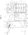
- a recording system 1 shown in FIG. 1 includes, as an example, a recording apparatus 2, a relay apparatus 3, and a post-processing apparatus 5 arranged in this order from right to left in FIG. 1 .
- FIG. 1 is a front view, and a user can perform various work in front of the system.
- the recording apparatus 2 performs recording on a sheet-shaped medium P transported thereto.
- the relay apparatus 3 receives the medium P after the recording from the recording apparatus 2 and delivers the medium P to the post-processing apparatus 5.
- the post-processing apparatus 5 performs, on the received medium P, post-processing which is represented by binding processing.
- the recording apparatus 2, the relay apparatus 3, and the post-processing apparatus 5 will be further described in this order.
- the recording apparatus 2 is configured as a multifunction machine including a printer unit 7 that includes a line head 12, which serves as a recording unit that performs recording on the medium P, and a scanner unit 8 which is an example of an image reading device.
- the line head 12 is configured as a so-called ink jet recording head that discharges ink, which is liquid, onto the medium P to perform recording.
- a cassette accommodation portion 11 including a plurality of medium accommodation cassettes 9 is provided below the printer unit 7.
- the medium P stored in the medium accommodation cassette 9 is sent to a recording region of the line head 12 through a feeding path 14, which is indicated by a solid line in FIG. 1 , so that recording is performed thereon.
- the medium P after recording performed by the line head 12 is sent to any of a first discharge path 15 which is a path through which the medium P is discharged to an after-recording discharge tray 10 provided above the line head 12, a second discharge path 16 which is a path through which the medium P is sent to the relay apparatus 3, and an inversion path 17 in which the medium P is inverted so that recording is performed on a rear surface of the medium P.
- first surface S1 one surface of the medium P
- second surface S2 another surface of the medium P
- recording is performed on the first surface S1 first and recording is performed on the second surface S2 after the medium P is inverted in the inversion path 17 when recording is to be performed on both surfaces of the medium P in the recording apparatus 2.
- recording is performed on both surfaces of the medium P, and a surface of the medium P on which recording is performed last is the second surface S2.
- the first surface S1 is a surface on which recording is performed last.
- the first discharge path 15 is indicated by a broken line
- the second discharge path 16 is indicated by an one-dot chain line
- the inversion path 17 is indicated by a two-dot chain line.
- the medium P is delivered to a reception path 20 of the relay apparatus 3 which is adjacent thereto.
- the inversion path 17 after recording is performed on the first surface S1 of the medium P, the medium P is inverted so that the second surface S2 faces the line head 12.
- one or more roller pairs are disposed as an example of a unit that transports the medium P.
- the recording apparatus 2 is provided with a control unit 18 that controls operations related to transportation of the medium P in the recording apparatus 2 and recording.
- the recording system 1 is configured such that the recording apparatus 2, the relay apparatus 3, and the post-processing apparatus 5 are mechanically and electrically coupled to each other and the medium P can be transported from the recording apparatus 2 to the post-processing apparatus 5.
- the control unit 18 can control various operations in the relay apparatus 3 and the post-processing apparatus 5 which are coupled to the recording apparatus 2.
- control unit 18 can control a medium transportation device 40 which will be described later.
- the recording system 1 is configured such that settings of various operations in the recording apparatus 2, the relay apparatus 3, and the post-processing apparatus 5 can be input and an instruction for execution of the various operations can be given via an operation panel (not shown).
- the operation panel can be provided in the recording apparatus 2, for example.
- the relay apparatus 3 delivers, to the post-processing apparatus 5, the medium P received from the recording apparatus 2.
- the relay apparatus 3 is disposed between the recording apparatus 2 and the post-processing apparatus 5.
- the medium P transported through the second discharge path 16 of the recording apparatus 2 is received by the relay apparatus 3 through the reception path 20 and is transported toward the post-processing apparatus 5.
- the reception path 20 is indicated by a solid line in FIG. 1 .
- the number of transportation paths for transportation of the medium P is two.
- the first transportation path is a path through which the medium P is transported from the reception path 20 to a confluence path 23 via a first switchback path 21 indicated by a dotted line in FIG. 1 .
- the second path is a path through which the medium P is transported from the reception path 20 to the confluence path 23 via a second switchback path 22 indicated by a two-dot chain line.
- the first switchback path 21 is a path through which the medium P is received in a direction along an arrow A1 and the medium P is switched back in a direction along an arrow A2.
- the second switchback path 22 is a path through which the medium P is received in a direction along an arrow B1 and the medium P is switched back in a direction along an arrow B2.
- the reception path 20 branches into the first switchback path 21 and the second switchback path 22 at a branching portion 25.
- the branching portion 25 is provided with a flap (not shown) that switches the destination of the medium P to any of the first switchback path 21 and the second switchback path 22.
- first switchback path 21 and the second switchback path 22 join each other at a junction portion 26. Therefore, regardless of whether the medium P from the reception path 20 is sent to the first switchback path 21 or the second switchback path 22, the medium P can be delivered to the post-processing apparatus 5 via the common confluence path 23.
- the medium P transported through the confluence path 23 is delivered to a first transportation path 35 of the post-processing apparatus 5 from a side surface of the relay apparatus 3 in a +Y direction.
- a transportation roller pair (not shown) are disposed as an example of a unit that transports the medium P.
- the mediums P entering the relay apparatus 3 are alternately sent to the transportation path through the first switchback path 21 and the transportation path through the second switchback path 22. Therefore, medium transportation throughput in the relay apparatus 3 can be increased.
- the medium P on which recording is performed by the recording apparatus 2 is delivered from the recording apparatus 2 to the post-processing apparatus 5 via the relay apparatus 3, a transportation time taken for the medium P after the recording to be sent to the post-processing apparatus 5 can be lengthened and drying of the medium P can be promoted until the medium P reaches the post-processing apparatus 5.
- the relay apparatus 3 may be omitted so that the post-processing apparatus 5 and the recording apparatus 2 are directly coupled to each other. That is, the post-processing apparatus 5 may be indirectly coupled to the recording apparatus 2 or be directly coupled to the recording apparatus 2.
- the post-processing apparatus 5 includes, as an example of a post-processing unit, a processing unit 30 that performs binding processing.
- the binding processing is, for example, processing of binding one corner portions of the mediums P or one sides of the mediums P. That is, in the present embodiment, the processing unit 30 is a stapler that performs the binding processing of piling the plurality of mediums P and binding end portions thereof. Note that the processing unit 30 is not limited thereto and may be configured to perform other processing such as punching processing of punching a hole at a predetermined position in the medium P.
- the post-processing apparatus 5 includes the first transportation path 35 that leads to the processing unit 30. That is, the medium P received by the post-processing apparatus 5 is transported through the first transportation path 35 indicated by a solid line in FIG. 1 .
- the mediums P transported through the first transportation path 35 are sent to a processing tray 31 and stacked on the processing tray 31 with trailing ends thereof in a transportation direction aligned with each other. When a predetermined number of the mediums P are stacked on the processing tray 31, the binding processing is performed by the processing unit 30.
- the mediums P processed by the processing unit 30 are discharged toward a main tray 33 by a discharge unit (not shown).
- a second transportation path 36 which branches off from the first transportation path 35 at a branching portion 37, is coupled to the first transportation path 35.
- the second transportation path 36 is a path through which the medium P is discharged to an upper tray 34 provided at an upper portion of the post-processing apparatus 5. On the upper tray 34, the mediums P that are not to be processed can be stacked.
- each of the recording apparatus 2, the relay apparatus 3, and the post-processing apparatus 5 includes one medium transportation device 40.
- at least one of the recording apparatus 2, the relay apparatus 3, and the post-processing apparatus 5 may be provided with the medium transportation device 40.
- the recording apparatus 2, the relay apparatus 3, and the post-processing apparatus 5 may be provided with a plurality of the medium transportation devices 40.
- a position where the medium transportation device 40 is provided in the recording apparatus 2, the relay apparatus 3, and the post-processing apparatus 5 is not limited to a position shown in FIG. 1 and the medium transportation device 40 may be provided at another position.
- the medium transportation device 40 has a function of correcting a curl of the medium P, and can also be referred to as a curl correction device from this viewpoint.
- the medium transportation device 40 corrects a curl of the medium P with a transportation roller pair 41 which will be described later.
- a device to which the transportation roller pair 41 can be detachably attached and that is in a state where the transportation roller pair 41 is not mounted therein may also be used as the medium transportation device 40.
- the recording apparatus 2, the relay apparatus 3, or the post-processing apparatus 5 when the recording apparatus 2, the relay apparatus 3, or the post-processing apparatus 5 is provided with the medium transportation device 40, a device to which the medium transportation device 40 can be detachably attached and that is in a state where the medium transportation device 40 is not mounted therein may also be used as the recording apparatus 2, the relay apparatus 3, or the post-processing apparatus 5.
- the medium transportation device 40 is provided in the second discharge path 16 as shown in FIG. 1 , for example. According to such a configuration, a curl of the medium P can be corrected before the medium P on which recording is finished is transported to the relay apparatus 3 or the post-processing apparatus 5.
- the medium transportation device 40 is provided in the confluence path 23 as shown in FIG. 1 , for example. According to such a configuration, a curl of the medium P can be corrected before the medium P is transported to the post-processing apparatus 5 even when the medium transportation device 40 is not provided for each of the switchback paths 21 and 22.
- the medium transportation device 40 is provided in the first transportation path 35 as shown in FIG. 1 , for example. According to such a configuration, a curl of the medium P can be corrected before the medium P on which recording is finished is transported to the processing unit 30.
- each of the embodiments of the medium transportation device will be referred to as, for example, a medium transportation device 40A or the like with a capital alphabet letter added to the reference numeral "40".
- the embodiments will be collectively referred to as the medium transportation devices 40. Note that repetitive description about the common features between the embodiments will not be made. In addition, the action and effect described in one of the embodiments can also be achieved in the other embodiments regarding the technically common features therebetween.
- a basic principle of curl correction in the medium transportation device 40 will be described with reference to FIGS. 2 and 3 .
- the medium transportation device 40 corrects a curl of the medium P by causing the medium P to be nipped by the transportation roller pair 41 including two rollers facing each other. Both or one of the two rollers facing each other is an uneven roller 45, and the medium P is nipped by the transportation roller pair 41 including the uneven roller 45 so that the curl of the medium is corrected.
- the uneven roller 45 includes a plurality of protrusion portions 61 that are formed along a circumferential direction and an axial direction and gaps between the plurality of protrusion portions 61 in the circumferential direction and the axial direction are recess portions 62. That is, a surface of the uneven roller 45 that comes into contact with the medium P is provided with a plurality of protrusions and recesses.
- the protrusion portions 61 are disposed at pitches ⁇ a in the circumferential direction.
- the uneven roller 45 is driven by a motor.
- the two uneven rollers 45 are coupled to each other by a gear and then are rotationally driven in synchronization.
- the present disclosure is not limited to such a driving method.
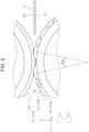
- FIG. 2 is an example of the transportation roller pair 41 in which only one of the two rollers facing each other is the uneven roller 45 and is an enlarged view showing a nip region of a transportation roller pair 41A in which one facing roller is the uneven roller 45 and another facing roller is an elastic roller 46.
- the first surface S1 of the medium P comes into contact with the uneven roller 45.
- the second surface S2 may come into contact with the uneven roller 45.
- the elastic roller 46 is formed of, for example, sponge and can be elastically deformed when coming into contact with the protrusions and recesses of the uneven roller 45.
- the uneven roller 45 is driven in a rotation direction C2 by a motor and the elastic roller 46 is driven to rotate in a rotation direction C1.
- a curl of the medium P is corrected when the medium P is nipped by the uneven roller 45 and the elastic roller 46.
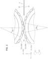
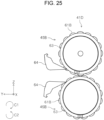
- FIG. 3 is an example of the transportation roller pair 41 in which both of the two rollers facing each other are the uneven rollers 45 and is an enlarged view showing a nip region of a transportation roller pair 41B in which both of the two rollers facing each other are the uneven rollers 45.
- the uneven roller 45 on a lower side is driven in the rotation direction C2 by a motor and the uneven roller 45 on an upper side is driven in the rotation direction C1 by a motor.
- a curl of the medium P is corrected when the medium P is nipped by the two uneven rollers 45.
- the axial direction of the uneven roller 45 is the X-axis direction in all of embodiments which will be described below.
- a +X direction is an example of a first direction
- a -X direction is an example of a second direction.
- the uneven roller 45 includes a shaft portion 49, a reference portion 51 mounted on the shaft portion 49, a ring portion 52 that is positioned closer to a side, to which the +X direction extends, than the reference portion 51 is and that is mounted on the shaft portion 49, and a restriction portion 53 that is positioned closer to the side, to which the +X direction extends, than the ring portion 52 is and that is mounted on the shaft portion 49 to restrict movement of the ring portion 52 in the +X direction.
- the ring portion 52 is composed of a plurality of uneven rings 60 disposed along the axial direction, the uneven ring 60 including a plurality of the protrusion portions 61 disposed along the circumferential direction.
- the shaft portion 49 is formed of metal.
- the reference portion 51 is formed of resin.
- the reference portion 51 is formed of polyoxymethylene (POM).
- POM polyoxymethylene
- the reference portion 51 is a cylindrical member, has an inner diameter slightly larger than the outer diameter of the shaft portion 49, and is formed to be slidable along the axial direction and not to wobble in a radial direction when being slid onto the shaft portion 49.
- the restriction portion 53 is formed of resin.
- the restriction portion 53 is formed of polyoxymethylene (POM).
- POM polyoxymethylene
- the restriction portion 53 is a cylindrical member, has an inner diameter slightly larger than the outer diameter of the shaft portion 49, and is formed to be slidable along the axial direction and not to wobble in the radial direction when being slid onto the shaft portion 49.
- the uneven ring 60 is formed of resin.
- the uneven ring 60 is formed of polyoxymethylene (POM).
- POM polyoxymethylene
- the uneven ring 60 has an inner diameter slightly larger than the outer diameter of the shaft portion 49 and is formed to be slidable along the axial direction and not to wobble in the radial direction when being slid onto the shaft portion 49.
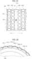
- the uneven roller 45A is a roller with a roller surface having a higher protrusion and recess density than an uneven roller 45B which will be described later.
- the uneven roller 45A includes a shaft portion 49A, a reference portion 51A mounted on the shaft portion 49A, a ring portion 52A that is positioned closer to a side, to which the +X direction extends, than the reference portion 51A is and that is mounted on the shaft portion 49A, and a restriction portion 53A that is positioned closer to the side, to which the +X direction extends, than the ring portion 52A is and that is mounted on the shaft portion 49A to restrict movement of the ring portion 52A in the +X direction. Furthermore, the uneven roller 45A includes a spring 54 that presses the restriction portion 53A in the -X direction and a stopper 55 that restricts movement of the spring 54 in the +X direction.
- a method of manufacturing the uneven roller 45A includes steps S101, S102, and S103 shown in FIG. 13 .
- Step S101 is a step of mounting the reference portion 51A onto the shaft portion 49A.
- Step S102 is a step of forming the ring portion 52A by repeating a step of sliding an uneven ring 60A, which includes a plurality of protrusion portions 61A disposed along the circumferential direction, onto the shaft portion 49A toward the reference portion 51A a plurality of times.
- Step S103 is a step of mounting, onto the shaft portion 49A, the restriction portion 53A that restricts movement of the ring portion 52A in a direction away from the reference portion 51A.
- a hole 51a is formed at the reference portion 51A, and a hole 49a is formed at the shaft portion 49A.
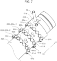
- the reference portion 51A is slid onto the shaft portion 49A, and then a fixation pin 56 is press-fitted into the hole 51a and the hole 49a as indicated by an arrow e1 in FIG. 7 in a state where the hole 51a coincides with the hole 49a. Accordingly, the reference portion 51A is fixed so as not to move in the axial direction and the circumferential direction with respect to the shaft portion 49A.
- the manufacturing of the uneven roller 45A includes a first step (the step S101 in FIG. 13 ) of mounting the reference portion 51A onto the shaft portion 49A and fixing the reference portion 51A.
- a method of fixing the reference portion 51A with respect to the shaft portion 49A is not limited to a method of press-fitting the fixation pin 56 and may be other fixing methods such as a screw-fixing method or an adhesion-fixing method, for example.
- the ring portion 52A is formed.
- the ring portion 52A is formed by sequentially sliding a plurality of the uneven rings 60A in the -X direction, that is, toward the reference portion 51A as indicated by arrows e2 in FIG. 7 .
- the plurality of protrusion portions 61A are provided along the circumferential direction on a side to which the +X direction extends, that is, on a side on which the reference portion 51A engages with the uneven rings 60A.
- the reference portion 51A is provided with one protrusion portion row composed of the plurality of protrusion portions 61A disposed along the circumferential direction.
- a ring engagement projection 51b protruding in the +X direction is formed between some of the protrusion portions 61A adjacent to each other in the circumferential direction.
- reference portion 51A may not be provided with the protrusion portions 61A.
- the uneven ring 60A includes a ring-shaped base portion 60a that is fitted to the shaft portion 49A.
- the base portion 60a is provided with the plurality of protrusion portions 61A disposed along the circumferential direction.
- the uneven ring 60A is provided with one protrusion portion row composed of the plurality of protrusion portions 61A disposed along the circumferential direction.
- the protrusion portions 61A of the uneven ring 60A are provided to protrude in the +X direction with respect to the base portion 60a.
- a reference portion side engaging portion 60b that is open in the -X direction is formed at the base portion 60a (refer to FIG. 6 as well) and the ring engagement projection 51b of the reference portion 51A can be fitted to the reference portion side engaging portion 60b.
- the protrusion portion 61A of the uneven ring 60A enters a space between two protrusion portions 61A of the reference portion 51A that are adjacent to each other in the circumferential direction.
- the protrusion portion 61A of the reference portion 51A enters a space between two protrusion portions 61A of the uneven ring 60A that are adjacent to each other in the circumferential direction. That is, in an assembled state, the protrusion portion 61A of the reference portion 51A and the protrusion portion 61A of the uneven ring 60A adjacent to the reference portion 51A are disposed at different positions in the circumferential direction.
- the positions of the reference portion side engaging portion 60b and the ring engagement projection 51b in the circumferential direction are set such that the protrusion portions 61A can fit into each other as described above.
- the ring engagement projection 51b is in a state of being in a space below one protrusion portion 61A constituting the uneven ring 60A as shown in FIG. 8 .
- a restriction portion side engaging portion 60c protruding in the +X direction is formed between some of the protrusion portions 61A adjacent to each other in the circumferential direction.
- the restriction portion side engaging portion 60c can be fitted to the reference portion side engaging portion 60b of the uneven ring 60A adjacent thereto.
- the reference portion side engaging portion 60b can be used not only for the positioning of the uneven ring 60A with respect to the reference portion 51A but also for the positioning of the uneven rings 60A that are adjacent to each other.
- the restriction portion side engaging portion 60c can be used not only for the positioning of the uneven rings 60A that are adjacent to each other but also for the positioning of the uneven ring 60A with respect to the restriction portion 53A which will be described later.
- the protrusion portion 61A of one of the uneven rings 60A enters a space between two protrusion portions 61A of another uneven ring 60A.
- an uneven ring indicated by a reference numeral "60A-1" in FIG. 7 is referred to as a first uneven ring and an uneven ring indicated by a reference numeral "60A-2" is referred to as a second uneven ring
- the protrusion portion 61A of a second uneven ring 60A-2 enters a space between two adjacent protrusion portions 61A of a first uneven ring 60A-1.
- the protrusion portion 61A of the first uneven ring 60A-1 enters a space between two adjacent projection portions 61A of the second uneven ring 60A-2. That is, in the assembled state, the protrusion portion 61A of the first uneven ring 60A-1 and the protrusion portion 61A of the second uneven ring 60A-2 are disposed at different positions in the circumferential direction.
- a reference numeral "61a” indicates a first protrusion portion row composed of the protrusion portions 61A of the first uneven ring 60A-1 and a reference numeral “61b” indicates a second protrusion portion row composed of the protrusion portions 61A of the second uneven ring 60A-2.
- the protrusion portions 61A of a first protrusion portion row 61a and the protrusion portions 61A of a second protrusion portion row 61b are disposed at different positions in the circumferential direction.
- the positions of the reference portion side engaging portion 60b and the restriction portion side engaging portion 60c in the circumferential direction are set such that the protrusion portions 61A can fit into each other as described above.
- the restriction portion 53A is slid onto the shaft portion 49A as indicated by an arrow e3 in FIG. 9 and then fixed.
- the restriction portion 53A includes a cylindrical first base portion 53c, which is closer to the side, to which the +X direction extends, than a flange portion 53e having the largest outer diameter is, and a cylindrical second base portion 53d, which is closer to the side, to which the -X direction extends, than the flange portion 53e is.
- a long hole 53b is formed at the first base portion 53c.
- the long hole 53b is a hole extending in the X-axis direction, that is, in the axial direction.
- a hole (not shown) into which the fixation pin 56 can be press-fitted is formed at the shaft portion 49A.
- the fixation pin 56 is press-fitted as indicated by an arrow e4 in FIG. 9 . Accordingly, the restriction portion 53A is fixed so as not to move in the circumferential direction with respect to the shaft portion 49A.
- the restriction portion 53A is in a state of being slidable in the X-axis direction within a formation range of the long hole 53b.
- a plurality of the protrusion portions 61A are provided along the circumferential direction on a side closer to a side, to which the -X direction extends, than the flange portion 53e is, that is, on a side on which the restriction portion 53A engages with the uneven rings 60A.
- the protrusion portion 61A provided at the restriction portion 53A has a shape obtained when removing the half of the protrusion portion 61A of the uneven ring 60A in the axial direction.
- the restriction portion 53A is provided with one protrusion portion row composed of the plurality of protrusion portions 61A disposed along the circumferential direction. At a position where one protrusion portion 61A is disposed in the circumferential direction, a ring engagement recess portion 53a that is open in the -X direction is formed at the second base portion 53d and the restriction portion side engaging portion 60c of the uneven ring 60A can be fitted to the ring engagement recess portion 53a.
- restriction portion 53A may not be provided with the protrusion portions 61A.
- the protrusion portion 61A of the uneven ring 60A enters a space between two protrusion portions 61A of the restriction portion 53A that are adjacent to each other in the circumferential direction.
- the protrusion portion 61A of the restriction portion 53A enters a space between two protrusion portions 61A of the uneven ring 60A that are adjacent to each other in the circumferential direction. That is, in the assembled state, the protrusion portion 61A of the restriction portion 53A and the protrusion portion 61A of the uneven ring 60A adjacent to the restriction portion 53A are disposed at different positions in the circumferential direction.
- the positions of the ring engagement recess portion 53a and the restriction portion side engaging portion 60c in the circumferential direction are set such that the protrusion portions 61A can fit into each other as described above.
- the second base portion 53d is in a state of being in a space below the protrusion portions 61A constituting the uneven ring 60A.
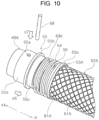
- a compression spring 54 which is an example of a pressing member, is slid onto the shaft portion 49A as indicated by an arrow e5 in FIG. 9 and then fitted to the first base portion 53c of the restriction portion 53A as shown in FIG. 10 .
- the inner diameter of the compression spring 54 is larger than the outer diameter of the first base portion 53c.
- the stopper 55 is slid onto the shaft portion 49A as indicated by an arrow e6 in FIG. 10 and then fixed.
- the stopper 55 includes a cylindrical first base portion 55d, which is closer to the side, to which the +X direction extends, than a flange portion 55b having the largest outer diameter is, and a cylindrical second base portion 55c, which is closer to the side, to which the -X direction extends, than the flange portion 55b is.
- a hole 55a is formed at the first base portion 55d.
- a hole (not shown) into which the fixation pin 56 can be press-fitted is formed at the shaft portion 49A.
- the fixation pin 56 is press-fitted as indicated by an arrow e7. Accordingly, the stopper 55 is fixed so as not to move in the axial direction and the circumferential direction with respect to the shaft portion 49A.
- the second base portion 55c enters the inside of the compression spring 54.
- the outer diameters of the flange portion 53e of the restriction portion 53A and the flange portion 55b of the stopper 55 are larger than the inner diameter of the compression spring 54 and the free length of the compression spring 54 is larger than a distance between the flange portion 53e of the restriction portion 53A and the flange portion 55b of the stopper 55 in the axial direction. Therefore, the compression spring 54 applies a pressing force in the -X direction to the flange portion 53e of the restriction portion 53A.
- the plurality of uneven rings 60A constituting the ring portion 52A are pressed toward the reference portion 51A in the -X direction and there is no wobbling between two uneven rings 60A that are adjacent to each other between the reference portion 51A and the restriction portion 53A.
- the uneven roller 45A described above has a configuration in which the protrusion portions 61A overlap with each other in the axial direction. However, a configuration in which the protrusion portions 61A do not overlap with each other in the axial direction may also be adopted.
- FIG. 11 shows the uneven roller 45B configured in such a manner, and a ring portion 52B is composed of a plurality of uneven rings 60B.
- the uneven ring 60B includes the ring-shaped base portion 60a that is fitted to the shaft portion 49A.
- the base portion 60a is provided with a plurality of protrusion portions 61B disposed along the circumferential direction.
- the uneven ring 60B is provided with one protrusion portion row composed of the plurality of protrusion portions 61B disposed along the circumferential direction.
- the reference portion side engaging portion 60b that protrudes in the -X direction is formed at the base portion 60a and the reference portion side engaging portion 60b can be fitted to a ring engagement recess portion 51c (refer to FIG. 11 ) of a reference portion 51B.
- restriction portion side engaging portion 60c that is open in the +X direction is formed between some of the protrusion portions 61B adjacent to each other in the circumferential direction at the base portion 60a and the reference portion side engaging portion 60b of the uneven ring 60B adjacent to the restriction portion side engaging portion 60c can be fitted to the restriction portion side engaging portion 60c.
- the reference portion side engaging portion 60b can be used not only engagement with respect to the reference portion 51B but also for the positioning of the uneven rings 60B that are adjacent to each other.
- the restriction portion side engaging portion 60c is also used for the positioning of the uneven ring 60B with respect to the restriction portion 53 (not shown) corresponding to the above-described restriction portion 53A.
- the reference portion side engaging portion 60b of the uneven ring 60B is formed in a protruding shape and the restriction portion side engaging portion 60c of the uneven ring 60B is formed in a recessed shape.
- the reference portion side engaging portion 60b of the uneven ring 60B may also be formed in a recessed shape and the restriction portion side engaging portion 60c of the uneven ring 60B may also be formed in a protruding shape.
- the protrusion portion 61B of one uneven ring 60B and the protrusion portion 61B of another uneven ring 60B are disposed at different positions in the circumferential direction.
- an uneven ring indicated by a reference numeral "60B-1" in FIG. 11 is referred to as a first uneven ring
- an uneven ring indicated by a reference numeral "60B-2" is referred to as a second uneven ring
- the protrusion portion 61B of a first uneven ring 60B-1 and the protrusion portion 61B of the second uneven ring 60B-2 are disposed at different positions in the circumferential direction.
- the positions of the reference portion side engaging portion 60b and the restriction portion side engaging portion 60c in the circumferential direction are set such that the protrusion portions 61B are disposed as described above.
- the uneven roller 45 includes the shaft portion 49, the reference portion 51 mounted on the shaft portion 49, the ring portion 52 that is positioned closer to the side, to which the +X direction extends, than the reference portion 51 is and that is mounted on the shaft portion 49, and the restriction portion 53 that is positioned closer to the side, to which the +X direction extends, than the ring portion 52 is and that is mounted on the shaft portion 49 to restrict movement of the ring portion 52 in the +X direction.
- the ring portion 52 is composed of a plurality of the uneven rings 60 disposed along the axial direction, the uneven ring 60 including the plurality of protrusion portions 61 along the circumferential direction.
- the uneven ring 60 is an uneven ring constituting the uneven roller 45 of which a surface coming into contact with the medium P is provided with a plurality of protrusions and recesses and can be mounted onto the shaft portion 49 constituting the uneven roller 45.
- the manufacturing method of the uneven roller 45 includes a step (the step S101 in FIG. 13 ) of mounting the reference portion 51 onto the shaft portion 49, a step (the step S102 in FIG. 13 ) of forming the ring portion 52 by repeating a step of sliding the uneven ring 60, which includes the plurality of protrusion portions 61 disposed along the circumferential direction, onto the shaft portion 49 toward the reference portion 51 a plurality of times, and a step (the step S103 in FIG. 13 ) of mounting, onto the shaft portion 49, the restriction portion 53 that restricts movement of the ring portion 52 in a direction away from the reference portion 51.
- the worn uneven ring 60 may be replaced with a new uneven ring or the worn uneven ring 60 of one uneven roller 45 may be replaced with the uneven ring 60 that is not worn so much.
- the reference portion 51 and the shaft portion 49 are configured as separate members. However, the reference portion 51 and the shaft portion 49 may be configured to be integrated with each other.
- the ring portion 52 may not be composed of the uneven rings 60 only and the ring portion 52 may include, for example, a flat ring of which an outer peripheral surface is flat. In such a case, it is preferable that the outermost diameter of the flat ring is smaller than the outermost diameter of the uneven ring 60. Note that an example of the flat ring will be described later as a facing ring 63.
- the plurality of uneven rings 60 that constitute the ring portion 52 have the same shape as each other. Accordingly, it is possible to suppress the cost of the uneven rings 60.
- the ring portion 52 may be composed of a plurality of types of uneven rings 60 having different shapes.
- the plurality of protrusion portions 61 of the uneven ring 60 are arranged in a row in the circumferential direction. Accordingly, the width of the uneven ring 60 can be reduced and the length of the ring portion 52 in the axial direction can be adjusted more easily.
- the uneven ring 60 may be provided with the plurality of protrusion portions 61 disposed in the axial direction.
- two adjacent uneven rings 60 of the uneven roller 45 can engage with each other. Accordingly, the two adjacent uneven rings 60 can be restrained from rotating relative to each other such that the phases thereof are made offset from each other.
- the uneven ring 60 includes the reference portion side engaging portion 60b that can engage with the reference portion 51. Accordingly, the uneven ring 60 that is adjacent to the reference portion 51 and the reference portion 51 can be restrained from rotating relative to each other such that the phases thereof are made offset from each other.
- reference portion side engaging portion 60b does not need to be provided for all of the plurality of uneven rings 60 and the reference portion side engaging portion 60b may be provided only for the uneven ring 60 adjacent to the reference portion 51.
- the uneven ring 60 includes the restriction portion side engaging portion 60c that can engage with the restriction portion 53. Accordingly, the uneven ring 60 that is adjacent to the restriction portion 53 and the restriction portion 53 can be restrained from rotating relative to each other such that the phases thereof are made offset from each other.
- restriction portion side engaging portion 60c does not need to be provided for all of the plurality of uneven rings 60 and the restriction portion side engaging portion 60c may be provided only for the uneven ring 60 adjacent to the restriction portion 53.
- the reference portion side engaging portion 60b and the restriction portion side engaging portion 60c can engage with each other. Accordingly, it is not necessary to provide a configuration for the positioning of the uneven rings 60 and thus the configuration can be simplified.
- the present disclosure is not limited to such a configuration, and a configuration in which the reference portion side engaging portion 60b and the restriction portion side engaging portion 60c cannot engage with each other may also be adopted.
- the protrusion portions 61 of one uneven ring 60 and the protrusion portions 61 of the uneven ring 60 that is adjacent to the one uneven ring 60 are disposed at different positions in the circumferential direction. Accordingly, it is possible to suppress formation of a noticeable line at the medium P along the axial direction, that is, a medium width direction.
- the uneven ring 60 includes the base portion 60a into which the shaft portion 49 is inserted and the protrusion portions 61 that protrude in a radial direction of the shaft portion 49 from the base portion 60a and the reference portion side engaging portion 60b is provided at the base portion 60a. Therefore, it is possible to provide the reference portion side engaging portion 60b without influence on disposition of the protrusion portions 61.
- the plurality of protrusion portion 61A may be configured to function as the restriction portion side engaging portion 60c. That is, since the protrusion portions 61A of the restriction portion 53A and the protrusion portions 61A of the uneven ring 60A of the uneven roller 45A fit into each other alternating in the circumferential direction, the uneven ring 60A adjacent to the restriction portion 53A and the restriction portion 53A can be restrained from rotating relative to each other such that the phases thereof are made offset from each other. That is, the plurality of protrusion portions 61A can function as the restriction portion side engaging portion 60c. According to such a configuration, the restriction portion side engaging portion 60c can be omitted, and an increase in cost of the uneven ring 60A can be suppressed.
- the uneven roller 45 since the restriction portion 53 is pressed in the -X direction, the plurality of uneven rings 60 are pressed against the reference portion 51 and formation of gaps between the plurality of uneven rings 60 is suppressed.
- the protrusion portions 61A of one uneven ring 60A and the protrusion portions 61A of the uneven ring 60A that is adjacent to the one uneven ring 60A are disposed at different positions in the circumferential direction and partially overlap with each other in the axial direction.
- the protrusion portions 61A are disposed to alternate along the axial direction. Accordingly, it is possible to suppress formation of a noticeable line at the medium P along the axial direction, that is, a medium width direction.
- the medium transportation device 40 may further include a heating unit that heats the shaft portion 49 constituting the uneven roller 45.
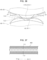
- FIG. 37 shows a cross section of a shaft portion 49D which is an example of the shaft portion 49 to be heated.
- the shaft portion 49D is formed in a hollow shape, a heater 112, which is an example of the heating unit, is provided inside the shaft portion 49D, and the shaft portion 49D is heated by the heater 112. According to such a configuration, the drying of the medium P can be performed in addition to curl correction of the medium P that is performed by the uneven roller 45.
- the medium transportation device 40 may include the claw portions 64 which will be described later.
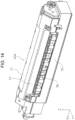
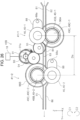
- a transportation roller pair 41C of the medium transportation device 40A includes an uneven roller 45C and the elastic roller 46 which is an example of a facing roller. Therefore, the configuration for the medium transportation device 40A to correct a curl of the medium P is equivalent to the configuration described with reference to FIG. 2 .
- An upstream guide 74 is provided upstream of the transportation roller pair 41C, and the medium P is guided to the transportation roller pair 41C by the upstream guide 74.
- the medium P nipped by the transportation roller pair 41C is guided downstream by a downstream guide 76.
- a wall portion 72 is provided above the downstream guide 76 to be hung from the cover 71 and thus leakage of an abnormal sound generated in the transportation roller pair 41C to the outside of the device can be suppressed. Therefore, it is preferable that the wall portion 72 is made of a material having favorable sound absorption properties.
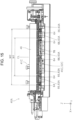
- the uneven roller 45C constituting the transportation roller pair 41C includes a ring portion 52C. Note that in FIG. 19 , the reference portion 51 and the restriction portion 53 are not shown.
- non-uneven regions 66 in which the protrusion portions 61 are not provided along the circumferential direction and protrusions and recesses and are not formed, are formed at portions of the ring portion 52C in the axial direction.
- the non-uneven regions 66 are formed by outer peripheral surfaces of facing rings 63.
- the facing ring 63 is formed of resin.
- the facing ring 63 is formed of polyoxymethylene (POM).
- POM polyoxymethylene
- the facing ring 63 has an inner diameter slightly larger than the outer diameter of a shaft portion 49B and is formed to be slidable along the axial direction and not to wobble in the radial direction when being slid onto the shaft portion 49B.
- the medium transportation device 40A includes the claw portions 64 provided at positions facing the facing rings 63 forming the non-uneven regions 66.
- the claw portions 64 are provided downstream of the uneven roller 45C in a medium transportation direction.
- the claw portions 64 are provided to be rotatable around rotary shafts 64a with respect to the downstream guide 76 and are pressed in the rotation direction C1 by tension springs 65, which are examples of a pressing member. Accordingly, tip ends of the claw portions 64, that is, upstream ends of the claw portions 64 that come into contact with the facing rings 63 are pressed against the facing rings 63.
- a reference numeral "CL" indicates a central position of the ring portion 52C in the medium width direction.
- a central position of the medium P in the medium width direction coincides with a central position CL regardless of the size of the medium P.
- the facing rings 63 and the claw portions 64 are provided at the central position CL and positions that are symmetrical with respect to the central position CL in the medium width direction.
- a reference numeral "W1" indicates a region in which a first medium P1 comes into contact with the uneven roller 45C and a reference numeral "W2" indicates a region in which a second medium P2, which has a size larger than that of the first medium P1, comes into contact with the uneven roller 45C.
- Facing rings 63A and the claw portions 64 are disposed slightly closer to an inner side than side ends of the first medium P1 are and are disposed slightly closer to the inner side than side ends of the second medium P2 are.
- a plurality of the facing rings 63A and the claw portions 64 are provided at intervals in the axial direction, that is, the medium width direction.
- the number of the facing rings 63A provided in the medium width direction and the number of the claw portions 64 provided in the medium width direction may be one.
- a reference numeral "Rd” indicates the outermost diameter of the uneven ring 60B and a reference numeral “Rc” indicates the outermost diameter of the facing ring 63A. As shown in the drawing, an outermost diameter Rc of the facing ring 63A is smaller than an outermost diameter Rd of the uneven ring 60B.
- a reference numeral "Cs1" is an outermost diameter circle corresponding to the outermost diameter Rd of the uneven ring 60B.
- a reference numeral “Cs2” indicates a circle that links points of contact where the protrusion portions 61B of two facing uneven rollers 45C come into contact with each other when a roller facing the uneven roller 45C is the uneven roller 45C also.
- a contact circle Cs2 Such a circle will be referred to as a "contact circle Cs2”.
- the contact circle Cs2 is a circle similar to the pitch circle of a gear.
- the outermost diameter Rc of the facing ring 63A is even smaller than the diameter of the contact circle Cs2.
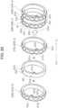
- FIG. 20 is a view showing engagement between the facing ring 63A and two uneven rings 60B sandwiching the facing ring 63A and shows a portion of an assembly step.
- the uneven ring 60B that is positioned closer to the side, to which the +X direction extends, than the facing ring 63A is will be referred to as a first uneven ring 60B-3 and the uneven ring 60B that is positioned closer to the side, to which the -X direction extends, than the facing ring 63A is will be referred to as a second uneven ring 60B-4.
- the facing ring 63A includes a first engaged portion 63b that can engage with the reference portion side engaging portion 60b of the first uneven ring 60B-3. Since the reference portion side engaging portion 60b has a protruding shape, the first engaged portion 63b is formed in a recessed shape that accommodates the protruding shape.
- the reference portion side engaging portion 60b is an example of a first engaging portion that can engage with the first engaged portion 63b.
- the facing ring 63A includes a second engaged portion 63a that can engage with the restriction portion side engaging portion 60c of the second uneven ring 60B-4. Since the restriction portion side engaging portion 60c has a recessed shape, the second engaged portion 63a is formed in a protruding shape that is fit to the recessed shape.
- the restriction portion side engaging portion 60c is an example of a second engaging portion that can engage with the second engaged portion 63a.
- the facing ring 63A is slid onto the shaft portion 49B and then the first uneven ring 60B-3 is slid onto the shaft portion 49B. Accordingly, as shown on the rightmost side in FIG. 20 , the first uneven ring 60B-3, the second uneven ring 60B-4, and the facing ring 63A enter a state of being combined with each other.
- the protrusion portions 61B of the two uneven rings 60B-3 and 60B-4 sandwiching the facing ring 63A are disposed at the same positions in the circumferential direction.
- a dimension of the facing ring 63A in a width direction is substantially equal to a dimension of the uneven ring 60B in the width direction.
- a hole 63c is formed at a portion of an outer peripheral surface of the facing ring 63A in the circumferential direction.
- a scribe line 49b which is an example of a mark, is formed along the circumferential direction.
- the scribe line 49b is formed in advance in a step of manufacturing the shaft portion 49B. Accordingly, when the facing ring 63A is slid onto the shaft portion 49B, the scribe line 49b in the hole 63c can be visually recognized as shown in FIG. 21 in a case where the facing ring 63A is disposed at a correct position in the axial direction. That is, it is possible to check whether or not the facing ring 63A is disposed at the correct position.
- FIG. 23 shows a facing ring 63B according to another embodiment, and the facing ring 63B is applied to the uneven ring 60A described with reference to FIGS. 4 to 10 .
- the uneven ring 60A that is positioned closer to the side, to which the +X direction extends, than the facing ring 63B is will be referred to as a first uneven ring 60A-3 and the uneven ring 60A that is positioned closer to the side, to which the -X direction extends, than the facing ring 63B is will be referred to as a second uneven ring 60A-4.
- the facing ring 63B includes the first engaged portion 63b that can engage with the reference portion side engaging portion 60b of the first uneven ring 60A-3. Since the reference portion side engaging portion 60b has a recessed shape, the first engaged portion 63b is formed in a protruding shape that is fit to the recessed shape.
- the reference portion side engaging portion 60b is an example of a first engaging portion that can engage with the first engaged portion 63b.
- the facing ring 63B includes the second engaged portion 63a that can engage with the restriction portion side engaging portion 60c of the second uneven ring 60A-4. Since the restriction portion side engaging portion 60c has a protruding shape, the second engaged portion 63a is formed in a recessed shape that accommodates the protruding shape.
- the restriction portion side engaging portion 60c is an example of a second engaging portion that can engage with the second engaged portion 63a.
- the facing ring 63B is slid onto the shaft portion 49B and then the first uneven ring 60A-3 is slid onto the shaft portion 49B. Accordingly, as shown on the rightmost side in FIG. 23 , the first uneven ring 60A-3, the second uneven ring 60A-4, and the facing ring 63B enter a state of being combined with each other.
- the protrusion portions 61A of the two uneven rings 60A sandwiching the facing ring 63B are disposed at the same positions in the circumferential direction.
- a dimension of the facing ring 63B in the width direction is larger than that of the uneven ring 60A and is larger than that of the facing ring 63A described with reference to FIG. 21 .
- the dimension of the facing ring 63B in the width direction is two times the dimension of the facing ring 63A, which is described with reference to FIG. 21 , in the width direction.
- the medium transportation device 40 includes the uneven roller 45 of which a surface coming into contact with the medium P is provided with a plurality of protrusions and recesses, the elastic roller 46 that nips the medium P together with the uneven roller 45, and the claw portions 64 that guide the medium P to be separated from the uneven roller 45. Accordingly, it is possible to facilitate peeling the medium P off from the uneven roller 45.
- non-uneven regions 66 in which protrusions and recesses are not formed along the circumferential direction are formed at a portion of the uneven roller 45 in the axial direction and the claw portions 64 face the non-uneven regions 66. Therefore, wear on or damage to the claw portions 64 and the protrusions and recesses, which is caused when the claw portions 64 come into contact with protrusions and recesses, can be suppressed.
- claw portions 64 may abut outer peripheral surfaces of the non-uneven regions 66 or may be separated from the outer peripheral surfaces of the non-uneven regions 66.
- a contact position Sp therebetween is provided within the interior of an angle ⁇ 1 in the rotation direction C2 from a downstream position Np of a nip region between the facing ring 63 and the elastic roller 46.
- An example of the angle ⁇ 1 is 90°.
- Another example of the angle ⁇ 1 is 45°.
- a point EC1 indicates the central position of the facing ring 63
- a point EC2 indicates the central position of the elastic roller 46
- a straight line L1 is a straight line passing through the point EC1 and the point EC2.
- a straight line L2 is a straight line passing through the central position EC1 and is a straight line orthogonal to the straight line L1
- a straight line L3 is a straight line passing through the downstream position Np of the nip region and the central position EC1.
- the angle ⁇ 1 is an angle formed by the straight line L3 and the straight line L2.
- a straight line L4 is a straight line passing through the contact position Sp and is a straight line orthogonal to the straight line L1. It is preferable that an angle ⁇ 2 formed by an upper surface 64b of the claw portion 64 and the straight line L4 at the contact position Sp falls within a range of 0° to 20°. Accordingly, the medium P can be appropriately peeled off from the uneven roller 45.
- the outermost diameter Rc of the facing ring 63 is smaller than the outermost diameter Rd of the uneven ring 60. Accordingly, the tip end of the claw portion 64 can enter a space inside an outermost diameter circle Cs1 of the uneven ring 60 and it is possible to more reliably peel the medium P off from the uneven roller 45 with the claw portion 64.
- the first engaging portion that is, the reference portion side engaging portion 60b
- the second engaging portion that is, the restriction portion side engaging portion 60c
- an engaging portion for the positioning of the uneven rings 60 that are adjacent to each other does not need to also serve as an engaging portion for the positioning of the uneven ring 60 adjacent to the facing ring 63 and the facing ring 63 and the engaging portions may be configured separately from each other.
- the engaging portion for the positioning of the uneven ring 60 adjacent to the facing ring 63 and the facing ring 63 may be provided for only the uneven ring 60 adjacent to the facing ring 63 or may be provided for every uneven ring 60.
- the protrusion portions 61 of one uneven ring 60 and the protrusion portions 61 of another uneven ring 60 are disposed at different positions in the circumferential direction. Accordingly, it is possible to suppress formation of a noticeable line at the medium P along the axial direction, that is, a medium width direction.
- the facing ring 63 and the claw portion 64 are disposed at the central position CL, which is the center of the ring portion 52 in the medium width direction. Accordingly, right and left sides of the medium P can be evenly peeled off with respect to the central position CL in the medium width direction and thus the medium P can be restrained from being skewed after being peeled off.
- the facing ring 63 and the claw portion 64 are provided at symmetrical positions with respect to the central position CL of the ring portion 52 in the medium width direction and are provided inside end portions, in the width direction, of the medium P having a predetermined size. Accordingly, right and left sides of the medium P can be evenly peeled off with respect to the central position CL in the medium width direction and thus the medium P can be restrained from being skewed after being peeled off.
- the scribe line 49b which is an example of a mark, is formed at a region where the facing ring 63 is mounted, that is, a portion of an outer peripheral surface of the shaft portion 49 onto which the facing ring 63 is mounted.
- at least a portion of the facing ring 63 that faces the scribe line 49b is configured such that the mark can be visually recognized and the hole 63c is formed at the facing ring 63 in the present embodiment. Accordingly, as described above, it is easy to recognize a position onto which the facing ring 63 is to be mounted when the uneven roller 45 is assembled.
- the facing ring 63 is configured such that the mark can be visually recognized, it is possible to easily check whether or not the facing ring 63 is mounted onto a correct position after the uneven roller 45 is assembled.
- regions A1, A2, and A3 in order from the central position CL to the axial ends are referred to as regions A1, A2, and A3 in order from the central position CL to the axial ends.
- regions A1, A2, and A3 in order from the central position CL to the axial ends a configuration in which the outermost diameters Rd at the regions increase in this order may also be adopted.
- an uneven ring 60B-11 is an uneven ring constituting the region A1.
- an uneven ring 60B-22 is an uneven ring constituting the region A2, and an uneven ring 60B-33 is an uneven ring constituting the region A3.
- the outermost diameter Rd of the uneven ring 60B-11 can be set to 30.5 mm
- the outermost diameter Rd of the uneven ring 60B-22 can be set to 31.0 mm
- the outermost diameter Rd of the uneven ring 60B-33 can be set to 31.5 mm.
- the outer diameters of the base portions 60a of the uneven rings can also be caused to increase toward the axial end.
- the outer diameter of a base portion 60a-1 of the uneven ring 60B-11 can be set to 28.5 mm
- the outer diameter of a base portion 60a-2 of the uneven ring 60B-22 can be set to 29.0 mm
- the outer diameter of a base portion 60a-3 of the uneven ring 60B-33 can be set to 29.5 mm.
- the protrusion portion 61B can be formed in the form of a portion of a sphere having a diameter of 3.0 mm.
- the outer diameter of the elastic roller 46 can be set to 35.0 mm, for example.
- the outermost diameter Rd of the uneven roller 45 does not need to stepwisely increase toward the axial ends as in the above-described embodiment and may continuously increase toward the axial ends.
- the uneven rings 60 that are the same as each other can be used between two facing rings 63. Therefore, it is possible to suppress an increase in cost of the uneven rings 60, and the assembly step is facilitated. That is, the uneven rings 60 that are the same as each other can be used in each of the regions A1, A2, and A3. Therefore, it is possible to suppress an increase in cost of the uneven rings 60, and the assembly step is facilitated.
- the outermost diameters Rc of a plurality of the facing rings 63 may be different from each other or may be equal to each other.
- the same components can be used for the plurality of facing rings 63 and an increase in cost of the component can be suppressed.
- the outer diameters of the base portions 60a may be different from each other as described above or may be equal to each other.
- a difference between the outermost diameters Rd of the uneven rings 60 is made by a difference between the amounts of protrusion of the protrusion portions 61 from the base portions 60a. Accordingly, the following action and effect can be achieved.
- the medium transportation device 40 may further include a heating unit that heats the shaft portion 49 constituting the uneven roller 45.
- FIG. 37 shows a cross section of the shaft portion 49D which is an example of the shaft portion 49 to be heated.
- the shaft portion 49D is formed in a hollow shape, a heater 112, which is an example of the heating unit, is provided inside the shaft portion 49D, and the shaft portion 49D is heated by the heater 112. According to such a configuration, the drying of the medium P can be performed in addition to curl correction of the medium P that is performed by the uneven roller 45.
- only one of facing rollers of the transportation roller pair 41C is configured as the uneven roller 45.
- both of the facing rollers may be configured as the uneven rollers 45.
- FIG. 25 shows an example of such a configuration and both of facing rollers of the transportation roller pair 41D are configured as the uneven rollers 45B.
- the protrusion portion 61B of one uneven roller 45B enters a space between two protrusion portions 61B of another uneven roller 45B.
- the claw portions 64 are provided for each of the two uneven rollers 45B. Accordingly, even when the medium P adheres to one of the two uneven rollers 45B, the medium P can be appropriately peeled off.
- claw portions 64 may be omitted from the above-described medium transportation device 40 and a medium transportation device may be configured to include the uneven roller 45 provided with the non-uneven regions 66.
- the medium transportation device 40 including a plurality of the transportation roller pairs 41 will be described with reference to FIGS. 26 to 31 .
- a medium transportation device 40B shown in FIG. 26 includes a first transportation roller pair 41-1 and a second transportation roller pair 41-2 that is positioned downstream of the first transportation roller pair 41-1 in the medium transportation direction.
- the medium P is guided to the first transportation roller pair 41-1 by a first upper guide 81 and a first lower guide 82.
- the medium P is guided to the second transportation roller pair 41-2 by a second upper guide 83 and a second lower guide 84.
- the medium P is guided downstream from the second transportation roller pair 41-2 by a third upper guide 85 and a third lower guide 86.
- the first transportation roller pair 41-1 nips and transports the medium P by means of a first uneven roller 45-1 and a first elastic roller 46-1 which is a first facing roller facing the first uneven roller 45-1.
- the first uneven roller 45-1 is rotationally driven in the rotation direction C2 by a motor 91 and the first elastic roller 46-1 is driven to rotate in the rotation direction C1.
- the second transportation roller pair 41-2 nips and transports the medium P by means of a second uneven roller 45-2 and a second elastic roller 46-2, which is a second facing roller facing the second uneven roller 45-2.
- the second uneven roller 45-2 is rotationally driven in the rotation direction C1 by the motor 91 and the second elastic roller 46-2 is driven to rotate in the rotation direction C2.
- the uneven rollers 45B are adopted and the uneven rings 60B described with reference to FIG. 11 are adopted.
- the present disclosure is not limited thereto.
- the uneven rings 60A described with reference to FIGS. 4 to 10 or other types of uneven rings 60 may also be adopted and the above-described facing ring 63 may be included between the plurality of uneven rings 60. That is, the first uneven roller 45-1 and the second uneven roller 45-2 may be any types of uneven rollers 45.
- the motor 91 controlled by the control unit 18 includes a motor gear 93 provided at a motor shaft 91a, and a gear 94 meshes with the motor gear 93.
- a roller gear 96B is provided at an axial end of the second uneven roller 45-2 and the roller gear 96B meshes with the gear 94 so that power is transmitted from the motor 91 to the second uneven roller 45-2.
- a gear 95 meshes with the gear 94.
- a roller gear 96A is provided at an axial end of the first uneven roller 45-1 and the roller gear 96A meshes with the gear 95 so that power is transmitted from the motor 91 to the first uneven roller 45-1.
- a drive belt or the like may also be used instead of the gears, for example.
- the elastic roller 46 is used as each of the first elastic roller 46-1 and the second elastic roller 46-2 and each elastic roller is pivotally supported by a roller supporting member 88 that is rotatable around a shaft 88a.
- the roller supporting member 88 that supports the first elastic roller 46-1 is pressed in the rotation direction C2 by a spring force of a pressing member (not shown) such as a spring and thus the first elastic roller 46-1 is pressed against the first uneven roller 45-1.
- roller supporting member 88 that supports the second elastic roller 46-2 is pressed in the rotation direction C1 by a spring force of a pressing member (not shown) such as a spring and thus the second elastic roller 46-2 is pressed against the second uneven roller 45-2.
- the first uneven roller 45-1 comes into contact with the first surface S1 of the medium P and the second uneven roller 45-2 comes into contact with the second surface S2 of the medium P and it is a matter of course that the first uneven roller 45-1 may come into contact with the second surface S2 of the medium P and the second uneven roller 45-2 may come into contact with the first surface S1 of the medium P.
- FIG. 27 shows the order in which protrusions and recesses that are formed at the medium P by the uneven roller 45B are formed and as indicated by a change from an uppermost view to a central view in FIG. 27 , protrusion portions Sc1 that protrude upward are formed at the second surface S2 of the medium P by the first uneven roller 45-1.
- the protrusion portions Sc1 are shapes formed in a state where the first uneven roller 45-1 is in contact with the medium P and the protrusion portions Sc1 may not remain at the medium P after the medium P passes through the first uneven roller 45-1.
- protrusion portions Sc2 that protrude downward are formed at the first surface S1 of the medium P by the second uneven roller 45-2.
- the protrusion portions Sc2 are shapes formed in a state where the second uneven roller 45-2 is in contact with the medium P and the protrusion portions Sc2 may not remain at the medium P after the medium P passes through the second uneven roller 45-2.
- a reference numeral "pa” indicates a formation interval between the protrusion portions Sc1 in the medium transportation direction and a formation interval between the protrusion portions Sc2 and the formation intervals correspond to a pitch interval between two protrusion portions 61 that are adjacent to each other in the circumferential direction.
- the formation interval will be referred to as a pitch interval pa.
- a formation interval between the protrusion portion Sc1 and the protrusion portion Sc2 in the medium transportation direction is pa/2, that is, the protrusion portion Sc2 is formed between two protrusion portions Sc1 in the medium transportation direction.
- the present disclosure is not limited thereto as long as positions at which the protrusion portions Sc1 are formed and positions at which the protrusion portions Sc2 are formed are offset from each other in the medium transportation direction instead of completely coinciding with each other in the medium transportation direction.
- the medium transportation device 40B includes frames 100 and 101 that support the first uneven roller 45-1 and the second uneven roller 45-2.
- the frames 100 and 101 are disposed at an interval in the medium width direction and rotatably support a shaft portion 49C-1 of the first uneven roller 45-1 and a shaft portion 49C-2 of the second uneven roller 45-2.
- the frames 100 and 101 rotatably support the shafts 88a.
- the motor 91 is attached to the frame 100 and the gears 94 and 95 are rotatably supported by the frame 100.
- the medium transportation device 40B includes a phase defining unit 102 that defines the phase of rotation of the first uneven roller 45-1 and the phase of rotation of the second uneven roller 45-2.
- the phase defining unit 102 according to the present embodiment is composed of phase alignment signs provided at the first uneven roller 45-1, the second uneven roller 45-2, and the frame 100 as shown in FIG. 29 .
- a reference numeral "49d-1” indicates a phase alignment sign provided at the shaft portion 49C-1 of the first uneven roller 45-1
- a reference numeral "49d-2” indicates a phase alignment sign provided at the shaft portion 49C-2 of the second uneven roller 45-2.
- phase alignment signs 49d-1 and 49d-2 are formed by partially cutting out outer peripheral portions of axial ends of the shaft portions 49C.
- the present disclosure is not limited thereto and marks formed by projections provided at axial end surfaces, engravement, coloring, or the like may also be adopted.
- phase alignment signs 101a and 101b indicate phase alignment signs provided at the frame 100.
- phase alignment signs 101a and 101b are formed by projections provided at a frame surface of the frame 100.
- present disclosure is not limited thereto marks formed by recess portions provided at the frame surface, notches, coloring, or the like may also be adopted.
- the phase alignment signs 49d-1 and 49d-2 provided at the shaft portions 49C indicate the positions of the protrusion portions 61B in the present embodiment.
- the reference portion 51 in the present embodiment is not shown in details in the drawing, the reference portion 51 has a configuration obtained when a gear is integrally formed with the reference portion 51B described with reference to FIG. 11 .
- the protrusion portions 61B of the uneven rings 60B adjacent to the reference portions 51B coincide with the phase alignment signs 49d-1 and 49d-2 provided at the shaft portions 49C.
- the gears are caused to mesh with each other such that the phase alignment sign 49d-1 of the first uneven roller 45-1 and the phase alignment sign 101a of the frame 100 coincide with each other and the phase alignment sign 49d-2 of the second uneven roller 45-2 and the phase alignment sign 101b of the frame 100 coincide with each other. Accordingly, a state where the protrusion portion 61B of the first uneven roller 45-1 abuts the medium P straight and the protrusion portion 61B of the second uneven roller 45-2 abuts the medium P straight can be achieved.
- positions at which the protrusion portions Sc1 are formed and positions at which the protrusion portions Sc2 are formed can be made offset from each other in the medium transportation direction as shown in FIG. 27 .
- phase alignment signs do not coincide with each other, it is possible to cause the phase alignment signs to coincide with each other, since it is possible to rotate the first uneven roller 45-1 and the second uneven roller 45-2 when removing the gear 95.
- the distance Da is a shaft-to-shaft distance of the first uneven roller 45-1 and the second uneven roller 45-2.
- the pitch interval pa can be obtained from the following equation (1), where pa is the pitch interval between two protrusion portions 61B of the uneven ring 60B that are adjacent to each other in the circumferential direction, ⁇ a (refer to FIG. 2 ) is a pitch angle, and Rd (refer to FIG. 18 ) is the outermost diameter of the uneven ring 60B.
- pa Rd ⁇ ⁇ ⁇ ⁇ a / 2 ⁇
- shaft-to-shaft distance Da can be set as in the following equation (2), for example.
- Da pa ⁇ n + pa / 2 n is a positive integer
- the positions of the protrusion portions 61B of the respective rollers after the phase alignment by making the positions of the protrusion portions 61B offset from the phase alignment signs or making the positions offset from the reference portions 51 in a rotation direction of the uneven rings 60B.
- the reference portion 51 it is also preferable to configure the reference portion 51 to be dedicated for each of the first uneven roller 45-1 and the second uneven roller 45-2.
- the first uneven roller 45-1 and the second uneven roller 45-2 are driven by one motor 91.
- each of the first uneven roller 45-1 and the second uneven roller 45-2 may be driven by a motor dedicated thereto.
- FIG. 30 shows a medium transportation device 40C having such a configuration, and the medium transportation device 40C includes motors 91A and 91B.
- a motor gear 93A is provided at the motor shaft 91a of the motor 91A and the motor gear 93A meshes with the roller gear 96A, so that the first uneven roller 45-1 is driven by the motor 91A.
- a motor gear 93B is provided at the motor shaft 91b of the motor 91B and the motor gear 93B meshes with the roller gear 96B, so that the second uneven roller 45-2 is driven by the motor 91B.
- the phases of rotation of the first uneven roller 45-1 and the second uneven roller 45-2 are controlled by the control unit 18.
- the control unit 18 controls the motors 91A and 91B such that the protrusion portions Sc1 that are formed at the second surface S2 of the medium P by the first uneven roller 45-1 and the protrusion portions Sc2 that are formed at the first surface S1 of the medium P by the second uneven roller 45-2 are made offset from each other in the medium transportation direction.
- control unit other than the control unit 18 that is provided in the recording apparatus 2 may control the phases of rotation of the first uneven roller 45-1 and the second uneven roller 45-2.
- each of the motors 91A and 91B is provided with a rotation scale 105 and an encoder 106.
- the rotation scale 105 is provided at the motor shaft 91a, and the encoder 106 detects rotation of the rotation scale 105 and transmits a detection signal to the control unit 18. Accordingly, the control unit 18 can detect the amounts of rotation of the motors 91A and 91B. That is, the control unit 18 can detect the amount of rotation of each of the first uneven roller 45-1 and the second uneven roller 45-2.
- a reference detection mark 105a is provided at a portion of the rotation scale 105 and the control unit 18 can detect the reference position of each of the first uneven roller 45-1 and the second uneven roller 45-2 with the encoder 106 detecting the reference detection mark 105a.
- the medium transportation devices 40B and 40C include the first transportation roller pair 41-1 and the second transportation roller pair 41-2, the first uneven roller 45-1 constituting the first transportation roller pair 41-1 comes into contact with the first surface S1 of the medium P, and the second uneven roller 45-2 constituting the second transportation roller pair 41-2 comes into contact with the second surface S2 of the medium P.
- the degree of a difference between protrusions and recesses formed at the first surface S1 of the medium P and protrusions and recesses formed at the second surface S2 can be suppressed and generation of a curl of which an inner side is at the first surface S1 or the second surface S2 can be suppressed.
- the position of contact of the protrusion portion 61B of the first uneven roller 45-1 and the position of contact of the protrusion portion 61B of the second uneven roller 45-2 are different from each other.
- a difference between the protrusions and recesses formed at the first surface S1 and the protrusions and recesses formed at the second surface S2 can be suppressed and generation of a curl of which the inner side is at the first surface S1 or the second surface S2 can be more effectively suppressed.
- the position of contact of the protrusion portion 61B of the second uneven roller 45-2 in the medium transportation direction is an intermediate position between the positions of contact of two protrusion portions 61B of the first uneven roller 45-1.
- the present disclosure is not limited thereto as long as the position of contact of the protrusion portion 61B of the first uneven roller 45-1 and the position of contact of the protrusion portion 61B of the second uneven roller 45-2 are different from each other.
- the medium transportation device 40B includes the phase defining unit 102 that defines the phase of rotation of the first uneven roller 45-1 and the phase of rotation of the second uneven roller 45-2. Accordingly, ease of assembly of the device is improved.
- the medium transportation device 40B includes the frame 100 that supports the first uneven roller 45-1 and the second uneven roller 45-2 and the phase defining unit 102 is composed of the phase alignment signs provided at the first uneven roller 45-1, the second uneven roller 45-2, and the frame 100.
- the phase defining unit 102 can be configured with a simple structure.
- the first uneven roller 45-1 and the second uneven roller 45-2 are driven by the motor 91 which is one drive source. Accordingly, the configuration of the device can be simplified and the cost of the device can be suppressed.
- the medium transportation device 40C includes the motor 91A that is a first drive source rotating the first uneven roller 45-1, the motor 91B that is a second drive source rotating the second uneven roller 45-2, the encoder 106 that is a detection unit provided for each motor and detecting rotation of a roller driven by each motor, and the control unit 18 that controls each motor.
- the control unit 18 controls each motor such that a position where the protrusion portion 61B of the first uneven roller 45-1 comes into contact with the medium P and a position where the protrusion portion 61B of the second uneven roller 45-2 comes into contact with the medium P are made different from each other.
- the encoder 106 may detect rotation of a roller itself although the encoder 106 detects rotation of the motor shaft 91a in the above-described embodiment.
- control unit 18 may adjust, based on a predetermined condition, the phase of rotation of the second uneven roller 45-2 with respect to the phase of rotation of the first uneven roller 45-1.
- the control unit 18 adjusts the phase of rotation of the second uneven roller 45-2 with respect to the phase of rotation of the first uneven roller 45-1 based on the predetermined condition, the adjustment can be performed such that the phase of rotation of the second uneven roller 45-2 with respect to the phase of rotation of the first uneven roller 45-1 is made appropriate.
- the protrusion portions 61B of the first protrusion portion row 61a (refer to FIG. 11 ) and the protrusion portions 61B of the second protrusion portion row 61b (refer to FIG. 11 ) are disposed at different positions in the circumferential direction. Therefore, it is possible to suppress formation of a noticeable line at the medium P along the axial direction, that is, the medium width direction.
- the protrusion portions 61A of the first protrusion portion row 61a (refer to FIG. 7 ) and the protrusion portions of the second protrusion portion row 61b (refer to FIG. 7 ) partially overlap with each other in the axial direction. Accordingly, it is possible to suppress formation of a noticeable line at the medium P along the medium transportation direction.
- the following action and effect can be achieved when the second surface S2 of the medium P (that is, a surface of the medium P that comes into contact with the second uneven roller 45-2) is a surface onto which ink is discharged last.
- the second surface S2 which is a surface that comes into contact with the second uneven roller 45-2 positioned downstream of the first uneven roller 45-1 in the medium transportation direction, is a surface onto which ink is discharged last, the length of time until contact between the second surface S2 and the second uneven roller 45-2 can be lengthened. Accordingly, the second surface S2 can come into contact with the second uneven roller 45-2 in a state where the second surface S2 is dried and thus the transfer of ink is suppressed.
- Such a configuration can be achieved by, for example, installing the medium transportation devices 40B and 40C in the second discharge path 16 (refer to FIG. 1 ) of the recording apparatus 2 in the recording system 1. This is because the second surface S2 faces an upper side when the second surface S2 on which recording is performed last in the recording apparatus 2 is transported through the second discharge path (refer to FIG. 1 ) as it is.
- the second surface S2 on which recording is performed last in the recording apparatus 2 faces a lower side. Therefore, in such a case, the following action and effect can be achieved when the positions of the uneven roller 45B and the elastic roller 46 are vertically reversed for each of the first transportation roller pair 41-1 and the second transportation roller pair 41-2 in the medium transportation devices 40B and 40C.
- the heater 112 that is, the heating unit
- the second surface S2 is a surface on which ink is discharged last
- transfer of ink is further suppressed since drying is further promoted by the first uneven roller 45-1 when the medium P reaches the second uneven roller 45-2.
- drying unit examples include the relay apparatus 3 described with reference to FIG. 1 . Therefore, in such a case, it is preferable that the medium transportation device 40B or the medium transportation device 40C is provided at a position in the relay apparatus 3 where the medium P is delivered to the post-processing apparatus 5, for example.
- both the first facing roller and the second facing roller are the elastic rollers 46.
- the present disclosure is not limited thereto and the first facing roller and the second facing roller may be uneven rollers 45.
- both rollers constituting the transportation roller pair 41 are the uneven rollers 45
- a medium transportation device in which both the rollers constituting the transportation roller pair 41 are the uneven rollers 45 will be referred to as a medium transportation device 40D although the entire body of the medium transportation device is not shown in the drawing.
- the medium transportation device 40D includes the transportation roller pair 41B.
- the transportation roller pair 41B includes a first uneven roller 45-11 and a second uneven roller 45-22.
- the first uneven roller 45-11 and the second uneven roller 45-22 are configured as the uneven rollers 45B.
- the protrusion portion 61B of one of the first uneven roller 45-11 and the second uneven roller 45-22 faces the recess portion 62 of another of the first uneven roller 45-11 and the second uneven roller 45-22 in the same manner as described with reference to FIG. 3 .
- FIG. 32 for the sake of convenience of illustration, only reference portions 51C and the uneven rings 60B adjacent thereto are shown and other uneven rings 60B and the shaft portions 49 are not shown. Note that the reference portions 51C are fixed to the shaft portions 49 by the fixation pins 56 in the same manner as described with reference to FIG. 7 .
- the reference portions 51C are integrally provided with gears 51e.
- the first uneven roller 45-11 and the second uneven roller 45-22 have the same reference portions 51C as each other.
- the gear 51e of the first uneven roller 45-11 will be referred to as a first gear 51e-1 and the gear 51e of the second uneven roller 45-22 will be referred to as a second gear 51e-2 as necessary.
- a first engaged portion 51j and a second engaged portion 51k are formed to be open in the +X direction at an end portion in the +X direction.
- the first engaged portion 51j and the second engaged portion 51k are formed at different positions in the circumferential direction.
- a first ring indication portion 51m is provided at the position of the first engaged portion 51j as a mark and a second ring indication portion 51n is provided at the position of the second engaged portion 51k as a mark.
- the first ring indication portion 51m and the second ring indication portion 51n are colored in different colors so that both the first ring indication portion 51m and the second ring indication portion 51n can be distinguished from each other.
- the colors of the first ring indication portion 51m and the second ring indication portion 51n may be the same as each other as long as different shapes, letters, or the like are provided as the first ring indication portion 51m and the second ring indication portion 51n since both the first ring indication portion 51m and the second ring indication portion 51n only need to be distinguished from each other.
- a first indication portion 51g and a second indication portion 51f are provided as marks at a gear surface of the gear 51e.
- the first indication portion 51g and the second indication portion 51f are formed at different positions in the circumferential direction.
- the first indication portion 51g and the second indication portion 51f are colored in different colors so that both the first indication portion 51g and the second indication portion 51f can be distinguished from each other.
- the colors of the first indication portion 51g and the second indication portion 51f may be the same as each other as long as different shapes, letters, or the like are provided as the first indication portion 51g and the second indication portion 51f since both the first indication portion 51g and the second indication portion 51f only need to be distinguished from each other.
- the reference portion side engaging portion 60b as the first engaging portion is fitted to the first engaged portion 51j.
- the reference portion side engaging portion 60b as the first engaging portion is fitted to the second engaged portion 51k.
- the first ring indication portion 51m and the second ring indication portion 51n colored in different colors can be used as signs at the time of assembly.
- the position of the first indication portion 51g of the first uneven roller 45-11 corresponds to the position of a tooth of the first gear 51e-1 and corresponds to the position of the recess portion 62 of the first uneven roller 45-11. Furthermore, the position of the second indication portion 51f of the first uneven roller 45-11 corresponds to the position of a tooth groove of the first gear 51e-1 and corresponds to the position of the recess portion 62 of the first uneven roller 45-11.
- the position of the first indication portion 51g of the second uneven roller 45-22 corresponds to the position of a tooth of the second gear 51e-2 and corresponds to the position of the protrusion portion 61B of the second uneven roller 45-22.
- the position of the second indication portion 51f of the second uneven roller 45-22 corresponds to the position of a tooth groove of the second gear 51e-2 and corresponds to the position of the protrusion portion 61B of the second uneven roller 45-22.
- first gear 51e-1 and the second gear 51e-2 are to be caused to mesh with each other
- the first gear 51e-1 and the second gear 51e-2 are caused to mesh with each other such that indication portions of which the colors are different from each other are brought together.
- the first indication portion 51g of the first gear 51e-1 and the second indication portion 51f of the second gear 51e-2 are brought together.
- the second indication portion 51f of the first gear 51e-1 and the first indication portion 51g of the second gear 51e-2 may also be brought together.
- the first gear 51e-1 and the second gear 51e-2 may be reversed.
- the transportation roller pair 41B included in the medium transportation device 40D includes the first uneven roller 45-11 and the second uneven roller 45-22 and the protrusion portion 61B of one of the first uneven roller 45-11 and the second uneven roller 45-22 faces the recess portion 62 of another of the first uneven roller 45-11 and the second uneven roller 45-22. Accordingly, the degree of a difference between protrusions and recesses formed at the first surface S1 of the medium P and protrusions and recesses formed at the second surface S2 can be suppressed and generation of a curl of which an inner side is at the first surface S1 or the second surface S2 can be suppressed.
- the medium transportation device 40D includes the first gear 51e-1 provided at the first uneven roller 45-11 and the second gear 51e-2 provided at the second uneven roller 45-22 and the first gear 51e-1 and the second gear 51e-2 mesh with each other. Accordingly, adjustment of the phase of rotation of the first uneven roller 45-11 and the phase of rotation of the second uneven roller 45-22 can be performed easily.
- the present disclosure is not limited to such a configuration, and another gear may be interposed between the first gear 51e-1 and the second gear 51e-2.
- a ratio between the number of the protrusion portions 61B of the first uneven roller 45-11 and the number of the protrusion portions 61B of the second uneven roller 45-22 is equal to a reduction ratio between the first gear 51e-1 and the second gear 51e-2. Accordingly, the phase of rotation of the first uneven roller 45-11 and the phase of rotation of the second uneven roller 45-22 being offset from each other as the rollers rotate can be suppressed.
- the ratio between the number of the protrusion portions 61B of the first uneven roller 45-11 and the number of the protrusion portions 61B of the second uneven roller 45-22 is 1 and the reduction ratio between the first gear 51e-1 and the second gear 51e-2 is also 1.
- the present disclosure is not limited thereto and for example, the number of teeth of the first gear 51e-1 may be two times the number of teeth of the second gear 51e-2 when the number of the protrusion portions 61B of the first uneven roller 45-11 is two times the number of the protrusion portions 61B of the second uneven roller 45-22.
- a gap dk1 is provided between the protrusion portion 61B of the first uneven roller 45-11 and the protrusion portion 61B of the second uneven roller 45-22 as shown in FIG. 36 .
- a pitch circle Cs3 (refer to FIG. 35 ) of the first gear 51e-1 is larger than the contact circle Cs2 (refer to FIG. 35 ) of the first uneven roller 45-11 and the pitch circle Cs3 (refer to FIG. 35 ) of the second gear 51e-2 is larger than the contact circle Cs2 (refer to FIG. 35 ) of the second uneven roller 45-22.
- the sum of the radius of a tip circle of the first gear 51e-1 and the radius of a tip circle of the second gear 51e-2 is larger than the sum of a distance from a rotation center of one of the first uneven roller 45-11 and the second uneven roller 45-22 to a tip end of the protrusion portion 61B and a distance from a rotation center of another of the first uneven roller 45-11 and the second uneven roller 45-22 to a bottom of the recess portion 62.
- the first tooth 51p of the first gear 51e-1 and the first tooth groove 51q of the second gear 51e-2 mesh with each other.
- the first recess portion 62-1 which is a recess portion of the first uneven roller 45-11 faces the first protrusion portion 61B-1 which is a protrusion portion of the second uneven roller 45-22. Accordingly, positional alignment of the first recess portion 62-1 of the first uneven roller 45-11 and the first protrusion portion 61B-1 of the second uneven roller 45-22 is facilitated.
- the second indication portion 51f of the first gear 51e-1 and the first indication portion 51g of the second gear 51e-2 may also be brought together.
- the result is as follows when a tooth groove of the first gear 51e-1 at which the second indication portion 51f is provided is referred to as a second tooth groove 51r and a tooth of the second gear 51e-2 at which the first indication portion 51g is provided is referred to as a second tooth 51s as shown in FIG. 34 .
- the first gear 51e-1 includes the first indication portion 51g indicating the position of the first tooth 51p and the second gear 51e-2 includes the second indication portion 51f indicating the position of the first tooth groove 51q. Accordingly, it is possible to easily cause the first tooth 51p to enter the first tooth groove 51q.
- the first indication portion 51g may not be provided at the position of a tooth and the first indication portion 51g may be provided at each of tooth grooves on both sides of a tooth to indicate the position of the tooth.
- the second indication portion 51f may be provided at each of teeth on both sides of a tooth groove to indicate the position of the tooth groove.
- the first uneven roller 45-11 and the second uneven roller 45-22 include the shaft portions 49, the reference portions 51 (51C) mounted on the shaft portions 49, the ring portions 52 that are positioned closer to the side, to which the +X direction extends, than the reference portions 51 are and that are mounted on the shaft portions 49, and the restriction portions 53 that are positioned closer to the side, to which the +X direction extends, than the ring portions 52 are and that are mounted on the shaft portions 49 to restrict movement of the ring portions 52 in the +X direction.
- the ring portions 52 are composed of the plurality of uneven rings 60 disposed along the axial direction, the uneven ring 60 including the plurality of the protrusion portions 61 disposed along the circumferential direction.
- the first gear 51e-1 is provided at the reference portion 51 of the first uneven roller 45-11 and the second gear 51e-2 is provided at the reference portion 51 of the second uneven roller 45-22.
- the uneven ring 60 includes the reference portion side engaging portion 60b that can engage with the reference portion 51 and the reference portion 51 includes the first engaged portion 51j that can engage with the reference portion side engaging portion 60b and the second engaged portion 51k that is provided at a position different from the position of the first engaged portion 51j in the circumferential direction.
- reference portion side engaging portion 60b that engages with the first engaged portion 51j or the second engaged portion 51k of the reference portion 51 may be provided only for the uneven ring 60 adjacent to the reference portion 51 or may be provided for every uneven ring 60.
- the first engaged portion 51j and the second engaged portion 51k of the reference portion 51 are provided and the reference portion side engaging portion 60b (that is, one engaging portion) is provided at the uneven ring 60 adjacent to the reference portion 51.
- the reference portion 51 may be provided with one engaged portion and the uneven ring 60 adjacent to the reference portion 51 may be provided with two engaging portions.
- the one engaged portion of the reference portion 51 has a protruding shape and the two engaging portions of the uneven ring 60 have recessed shapes.
- the uneven ring 60 includes the restriction portion side engaging portion 60c (refer to FIGS. 11 and 12 ) that can engage with the restriction portion 53 and the reference portion side engaging portion 60b and the restriction portion side engaging portion 60c can engage with each other. Accordingly, it is not necessary to provide a configuration for the positioning of the uneven rings 60 and thus the configuration can be simplified.
- the protrusion portions 61B of the first protrusion portion row 61a (refer to FIG. 11 ) and the protrusion portions 61B of the second protrusion portion row 61b (refer to FIG. 11 ) are disposed at different positions in the circumferential direction. Therefore, it is possible to suppress formation of a noticeable line at the medium P along the axial direction, that is, the medium width direction.
- the protrusion portions 61A of the first protrusion portion row 61a (refer to FIG. 7 ) and the protrusion portions of the second protrusion portion row 61b (refer to FIG. 7 ) partially overlap with each other in the axial direction. Accordingly, it is possible to suppress formation of a noticeable line at the medium P along the medium transportation direction.
- the drying of the medium P can be performed in addition to curl correction of the medium P.
Landscapes
- Engineering & Computer Science (AREA)
- Mechanical Engineering (AREA)
- Textile Engineering (AREA)
- Delivering By Means Of Belts And Rollers (AREA)
- Separation, Sorting, Adjustment, Or Bending Of Sheets To Be Conveyed (AREA)
- Accessory Devices And Overall Control Thereof (AREA)
- Paper Feeding For Electrophotography (AREA)
Abstract
Description
- The present application is based on, and claims priority from
JP Application Serial Number 2023-042800, filed March 17, 2023 - The present disclosure relates to an uneven roller of which a surface coming into contact with a medium, onto which liquid is discharged, is provided with protrusions and recesses. The present disclosure also relates to a medium transportation device including the uneven roller. The present disclosure also relates to a recording apparatus, a post-processing apparatus, and a relay apparatus each of which includes the medium transportation device. The present disclosure also relates to an uneven ring that constitutes an uneven roller of which a surface coming into contact with a medium, onto which liquid is discharged, is provided with a plurality of protrusions and recesses. The present disclosure also relates to a manufacturing method of an uneven roller.
- Disclosed in
JP-A-2007-168992 - Although a configuration in which the entire surface of a paper sheet is embossed by using a male roller and a female roller is disclosed in
JP-A-2007-168992 - The shape of a roller used to emboss a paper sheet is complicated in comparison with a normal roller, which is to be considered at the time of manufacture.
- According to an aspect of the present disclosure, there is provided an uneven roller of which a surface coming into contact with a medium, onto which liquid is discharged, is provided with a plurality of protrusions and recesses, the uneven roller including a shaft portion, a reference portion mounted on the shaft portion, a ring portion that is positioned closer to a side, to which a first direction along an axial direction of the shaft portion extends, than the reference portion is and that is mounted on the shaft portion, and a restriction portion that is positioned closer to the side, to which the first direction extends, than the ring portion is and that is mounted on the shaft portion to restrict movement of the ring portion in the first direction. The ring portion is composed of a plurality of uneven rings disposed along the axial direction, the uneven ring including a plurality of protrusion portions disposed along a circumferential direction.
- According to another aspect of the present disclosure, there is provided a medium transportation device including the above-described uneven roller that is rotationally driven and a facing roller nipping, together with the uneven roller, a medium onto which liquid is discharged.
- According to still another aspect of the present disclosure, there is provided a recording apparatus including a recording unit performing recording by discharging liquid onto a medium and the above-described medium transportation device that transports the medium on which the recording is performed by the recording unit.
- According to still another aspect of the present disclosure, there is provided a post-processing apparatus directly or indirectly coupled to a recording apparatus performing recording by discharging liquid onto a medium, the post-processing apparatus including a post-processing unit performing post-processing on the medium on which the recording is performed by the recording apparatus and the above-described medium transportation device that transports, toward the post-processing unit, the medium on which the recording is performed by the recording apparatus.
- According to still another aspect of the present disclosure, there is provided a relay apparatus that is disposed between a recording apparatus performing recording by discharging liquid onto a medium and a post-processing apparatus performing post-processing on the medium on which the recording is performed by the recording apparatus and that passes the medium from the recording apparatus to the post-processing apparatus, the relay apparatus including the above-described medium transportation device.
- According to still another aspect of the present disclosure, there is provided an uneven ring constituting an uneven roller of which a surface coming into contact with a medium, onto which liquid is discharged, is provided with a plurality of protrusions and recesses. The uneven ring is configured to be mounted on a shaft portion constituting the uneven roller and includes a plurality of protrusion portions disposed along a circumferential direction.
- According to still another aspect of the present disclosure, there is provided a manufacturing method of an uneven roller of which a surface coming into contact with a medium, onto which liquid is discharged, is provided with a plurality of protrusions and recesses, the manufacturing method including mounting a reference portion on a shaft portion, forming a ring portion by repeatedly sliding an uneven ring, which includes a plurality of protrusion portions disposed along a circumferential direction, onto the shaft portion toward the reference portion a plurality of times, and mounting, onto the shaft portion, a restriction portion restricting movement of the ring portion in a direction away from the reference portion.
-
-
FIG. 1 is a view showing an overall configuration of a recording system. -
FIG. 2 is a view showing a first basic configuration for curl correction. -
FIG. 3 is a view showing a second basic configuration for curl correction. -
FIG. 4 is a perspective view of an uneven roller. -
FIG. 5 is a partially enlarged perspective view of the uneven roller. -
FIG. 6 is a perspective view of an uneven ring. -
FIG. 7 is a perspective view showing a method of assembling the uneven roller. -
FIG. 8 is a cross-sectional perspective view of a portion of the uneven roller. -
FIG. 9 is a perspective view showing the method of assembling the uneven roller. -
FIG. 10 is a perspective view showing the method of assembling the uneven roller. -
FIG. 11 is a partially enlarged perspective view of an uneven roller. -
FIG. 12 is a perspective view of an uneven ring. -
FIG. 13 is a flowchart showing the flow of a method of manufacturing the uneven roller. -
FIG. 14 is an external perspective view of a medium transportation device. -
FIG. 15 is a front view of the inside of the medium transportation device. -
FIG. 16 is a partially enlarged perspective view of the inside of the medium transportation device. -
FIG. 17 is a cross-sectional view of the medium transportation device. -
FIG. 18 is a sectional view of an uneven roller. -
FIG. 19 is a plan view of the uneven roller. -
FIG. 20 is a perspective view showing a method of assembling the uneven roller. -
FIG. 21 is a partially enlarged view of the uneven roller. -
FIG. 22 is a view showing an embodiment in which outer diameters of an uneven roller are made different from each other. -
FIG. 23 is a perspective view showing a method of assembling an uneven roller. -
FIG. 24 is a view illustrating the disposition and the angle of contact of a claw portion with respect to a facing ring. -
FIG. 25 is a cross-sectional view of a transportation roller pair of which both of rollers facing each other are uneven rollers. -
FIG. 26 is a cross-sectional view of a medium transportation device including a plurality of transportation roller pairs. -
FIG. 27 is a view schematically showing protrusions and recesses formed at a medium. -
FIG. 28 is a perspective view of the medium transportation device including the plurality of transportation roller pairs. -
FIG. 29 is a side view of the medium transportation device including the plurality of transportation roller pairs. -
FIG. 30 is a cross-sectional view of a medium transportation device including a plurality of transportation roller pairs. -
FIG. 31 is a front view of an encoder provided at a motor. -
FIG. 32 is a perspective view of a transportation roller pair of which both of rollers facing each other are uneven rollers. -
FIG. 33 is a perspective view of a restriction portion. -
FIG. 34 is a view showing a first gear and a second gear meshing with each other. -
FIG. 35 is an enlarged view of part XXXV ofFIG. 34 . -
FIG. 36 is a view showing only an uneven roller in which gears inFIG. 35 are omitted. -
FIG. 37 is a sectional view of a shaft portion provided with a heater. - Hereinafter, the present disclosure will be schematically described.
- According to a first aspect of the present disclosure, there is provided an uneven roller of which a surface coming into contact with a medium, onto which liquid is discharged, is provided with a plurality of protrusions and recesses, the uneven roller including a shaft portion, a reference portion mounted on the shaft portion, a ring portion that is positioned closer to a side, to which a first direction along an axial direction of the shaft portion extends, than the reference portion is and that is mounted on the shaft portion, and a restriction portion that is positioned closer to the side, to which the first direction extends, than the ring portion is and that is mounted on the shaft portion to restrict movement of the ring portion in the first direction. The ring portion is composed of a plurality of uneven rings disposed along the axial direction, the uneven ring including a plurality of protrusion portions disposed along a circumferential direction.
- According to the present aspect, a plurality of protrusions are formed at the medium by the uneven roller, so that curl of the medium can be corrected. Here, since the ring portion of the uneven roller can be configured by mounting the plurality of uneven rings between the reference portion and the restriction portion, it is possible to easily configure the uneven rollers having different specifications by changing the shape of the uneven ring with the shaft portion used as a common component and thus the cost of members can be reduced.
- In addition, by changing the number of the uneven rings, it is possible to easily change the length of the ring portion in the axial direction and to easily manufacture the uneven rollers having different dimensions.
- In addition, a job to be performed when wear or the like of a portion of the ring portion occurs is simply replacing the uneven ring of a corresponding portion. Therefore, it is possible to suppress the required cost in comparison with the case of replacement of the entire uneven roller and to cope with requests for reuse and waste minimisation.
- A second aspect of the present disclosure is an aspect that is subordinate to the first aspect and in which the plurality of uneven rings constituting the ring portion have the same shape as each other.
- According to the present aspect, since the plurality of uneven rings constituting the ring portion have the same shape as each other, the cost of the uneven rings can be suppressed.
- A third aspect of the present disclosure is an aspect that is subordinate to the first aspect and in which the plurality of protrusion portions of the uneven ring are arranged in a row in the circumferential direction.
- According to the present aspect, since the plurality of protrusion portions of the uneven ring are arranged in a row in the circumferential direction, the width of the uneven rings can be made reduced. Accordingly, the length of the ring portion in the axial direction can be adjusted more easily.
- Note that the present aspect may be an aspect that is subordinate to the second aspect instead of being subordinate to the first aspect.
- A fourth aspect of the present disclosure is an aspect that is subordinate to the first aspect and in which two of the uneven rings that are adjacent to each other are configured to engage with each other.
- According to the present aspect, since the two of the uneven rings that are adjacent to each other are configured to engage with each other, the two adjacent uneven rings can be restrained from rotating relative to each other such that the phases thereof are made offset from each other.
- Note that the present aspect may be an aspect that is subordinate to the second aspect or the third aspect instead of being subordinate to the first aspect.
- A fifth aspect of the present disclosure is an aspect that is subordinate to the fourth aspect and in which the uneven ring includes a reference portion side engaging portion configured to engage with the reference portion.
- According to the present aspect, since the uneven ring includes the reference portion side engaging portion configured to engage with the reference portion, the uneven ring that is adjacent to the reference portion and the reference portion can be restrained from rotating relative to each other such that the phases thereof are made offset from each other.
- Note that the present aspect may be an aspect that is subordinate to any one of the first to third aspects instead of the fourth aspect.
- A sixth aspect of the present disclosure is an aspect that is subordinate to the fifth aspect and in which the uneven ring includes a restriction portion side engaging portion configured to engage with the restriction portion.
- According to the present aspect, since the uneven ring includes the restriction portion side engaging portion configured to engage with the restriction portion, the uneven ring that is adjacent to the restriction portion and the restriction portion can be restrained from rotating relative to each other such that the phases thereof are made offset from each other.
- Note that the present aspect may be an aspect that is subordinate to any one of the first to fourth aspects instead of the fifth aspect.
- A seventh aspect of the present disclosure is an aspect that is subordinate to the fourth aspect and in which the uneven ring includes a reference portion side engaging portion configured to engage with the reference portion and a restriction portion side engaging portion configured to engage with the restriction portion and the reference portion side engaging portion and the restriction portion side engaging portion are configured to engage with each other.
- According to the present aspect, since the uneven ring includes a reference portion side engaging portion configured to engage with the reference portion and a restriction portion side engaging portion configured to engage with the restriction portion and the reference portion side engaging portion and the restriction portion side engaging portion are configured to engage with each other, it is not necessary to separately provide a configuration for the positioning of the uneven rings and thus the configuration can be simplified.
- Note that the present aspect may be an aspect that is subordinate to any one of the first to third aspects instead of the fourth aspect.
- An eighth aspect of the present disclosure is an aspect that is subordinate to the seventh aspect and in which the plurality of uneven rings include a first uneven ring and a second uneven ring positioned closer to the side, to which the first direction extends, than the first uneven ring is and a plurality of protrusion portions of the first uneven ring and a plurality of protrusion portions of the second uneven ring are disposed at different positions in the circumferential direction in a state where the restriction portion side engaging portion of the first uneven ring and the reference portion side engaging portion of the second uneven ring engage with each other.
- According to the present aspect, since the plurality of protrusion portions of the first uneven ring and the plurality of protrusion portions of the second uneven ring are disposed at different positions in the circumferential direction, it is possible to suppress formation of a noticeable line at the medium along the axial direction, that is, a medium width direction.
- A ninth aspect of the present disclosure is an aspect that is subordinate to the seventh aspect and in which the uneven ring includes a base portion into which the shaft portion is inserted and the protrusion portions protruding in a radial direction of the shaft portion from the base portion and the reference portion side engaging portion is provided at the base portion.
- According to the present aspect, since the uneven ring includes the base portion into which the shaft portion is inserted and the protrusion portions protruding in the radial direction of the shaft portion from the base portion and the reference portion side engaging portion is provided at the base portion, it is possible to provide the reference portion side engaging portion without influence on disposition of the protrusion portions.
- Note that the present aspect may be an aspect that is subordinate to the fifth aspect or the eighth aspect instead of being subordinate to the seventh aspect.
- A tenth aspect of the present disclosure is an aspect that is subordinate to the seventh aspect and in which the uneven ring includes a base portion into which the shaft portion is inserted and the protrusion portions protruding in a radial direction of the shaft portion from the base portion and the restriction portion side engaging portion is provided at the base portion.
- According to the present aspect, since the uneven ring includes the base portion into which the shaft portion is inserted and the protrusion portions protruding in the radial direction of the shaft portion from the base portion and the restriction portion side engaging portion is provided at the base portion, it is possible to provide the restriction portion side engaging portion without influence on disposition of the protrusion portions.
- Note that the present aspect may be an aspect that is subordinate to the sixth aspect or the eighth aspect instead of being subordinate to the seventh aspect.
- An eleventh aspect of the present disclosure is an aspect that is subordinate to the seventh aspect and in which the uneven ring includes a base portion into which the shaft portion is inserted and the protrusion portions protruding in a radial direction of the shaft portion from the base portion and the plurality of protrusion portions are the reference portion side engaging portion.
- According to the present aspect, since the uneven ring includes the base portion into which the shaft portion is inserted and the protrusion portions protruding in the radial direction of the shaft portion from the base portion and the plurality of protrusion portions are the reference portion side engaging portions, dedicated reference portion side engaging portions do not need to be provided and an increase in cost of the uneven ring can be suppressed.
- Note that the present aspect may be an aspect that is subordinate to the fifth aspect or the eighth aspect instead of being subordinate to the seventh aspect.
- A twelfth aspect of the present disclosure is an aspect that is subordinate to the seventh aspect and in which the uneven ring includes a base portion into which the shaft portion is inserted and the protrusion portions protruding in a radial direction of the shaft portion from the base portion and the plurality of protrusion portions are the restriction portion side engaging portion.
- According to the present aspect, since the uneven ring includes the base portion into which the shaft portion is inserted and the protrusion portions protruding in the radial direction of the shaft portion from the base portion and the plurality of protrusion portions are the restriction portion side engaging portions, dedicated restriction portion side engaging portions do not need to be provided and an increase in cost of the uneven ring can be suppressed.
- Note that the present aspect may be an aspect that is subordinate to the sixth aspect or the eighth aspect instead of being subordinate to the seventh aspect.
- A thirteenth aspect of the present disclosure is an aspect that is subordinate to the first aspect and in which the restriction portion is pressed in a second direction which is a direction opposite to the first direction.
- According to the present aspect, since the restriction portion is pressed in the second direction which is a direction opposite to the first direction, the plurality of uneven rings are pressed against the reference portion and formation of gaps between the plurality of uneven rings is suppressed.
- Note that the present aspect may be an aspect that is subordinate to any one of the second to twelfth aspects instead of the first aspect.
- A fourteenth aspect of the present disclosure is an aspect that is subordinate to the first aspect and in which the plurality of uneven rings include a first uneven ring and a second uneven ring positioned closer to the side, to which the first direction extends, than the first uneven ring is, a plurality of protrusion portions of the first uneven ring and a plurality of protrusion portions of the second uneven ring are disposed at different positions in the circumferential direction, and the plurality of protrusion portions of the first uneven ring and the plurality of protrusion portions of the second uneven ring partially overlap with each other in the axial direction.
- According to the present aspect, since the plurality of protrusion portions of the first uneven ring and the plurality of protrusion portions of the second uneven ring are disposed at different positions in the circumferential direction, it is possible to suppress formation of a noticeable line at the medium along the axial direction, that is, a medium width direction.
- In addition, since the plurality of protrusion portions of the first uneven ring and the plurality of protrusion portions of the second uneven ring partially overlap with each other in the axial direction, it is possible to suppress formation of a noticeable line at the medium along a medium transportation direction.
- Note that the present aspect may be an aspect that is subordinate to any one of the second to thirteenth aspects instead of the first aspect.
- According to a fifteenth aspect of the present disclosure, there is provided a medium transportation device including the uneven roller that is described in any one of the first to fourteenth aspects and that is rotationally driven and a facing roller nipping, together with the uneven roller, a medium onto which liquid is discharged.
- According to the present aspect, in the medium transportation device, an advantageous effect of any one of the first to fourteenth aspects described above can be obtained.
- A sixteenth aspect of the present disclosure is an aspect that is subordinate to the fifteenth aspect and in which the medium transportation device further includes a heating unit heating the shaft portion.
- According to the present aspect, since the medium transportation device further includes the heating unit heating the shaft portion, the drying of the medium can be performed with the uneven roller in addition to curl correction of the medium.
- According to a seventeenth aspect of the present disclosure, there is provided a recording apparatus including a recording unit performing recording by discharging liquid onto a medium and the medium transportation device according to the fifteenth aspect that transports the medium on which the recording is performed by the recording unit.
- According to the present aspect, in the recording apparatus, an advantageous effect of any one of the first to fourteenth aspects described above can be obtained.
- According to an eighteenth aspect of the present disclosure, there is provided a post-processing apparatus directly or indirectly coupled to a recording apparatus performing recording by discharging liquid onto a medium, the post-processing apparatus including a post-processing unit performing post-processing on the medium on which the recording is performed by the recording apparatus and the medium transportation device according to the fifteenth aspect that transports, toward the post-processing unit, the medium on which the recording is performed by the recording apparatus.
- According to the present aspect, in the post-processing apparatus, an advantageous effect of any one of the first to fourteenth aspects described above can be obtained.
- According to a nineteenth aspect of the present disclosure, there is provided a relay apparatus that is disposed between a recording apparatus performing recording by discharging liquid onto a medium and a post-processing apparatus performing post-processing on the medium on which the recording is performed by the recording apparatus and that passes the medium from the recording apparatus to the post-processing apparatus, the relay apparatus including the medium transportation device according to the fifteenth aspect.
- According to the present aspect, in the relay apparatus, an advantageous effect of any one of the first to fourteenth aspects described above can be obtained.
- In addition, in the relay apparatus, since curl correction is performed by the uneven roller, the aligning property of the medium in the post-processing apparatus is improved and the precision of the post-processing is improved.
- According to a twentieth aspect of the present disclosure, there is provided an uneven ring constituting an uneven roller of which a surface coming into contact with a medium, onto which liquid is discharged, is provided with a plurality of protrusions and recesses. The uneven ring is configured to be mounted on a shaft portion constituting the uneven roller and includes a plurality of protrusion portions disposed along a circumferential direction.
- According to the present aspect, a plurality of protrusions are formed at the medium by the uneven roller, so that curl of the medium can be corrected. Here, since the uneven roller can be configured by mounting a plurality of the uneven rings on the shaft portion, it is possible to easily configure the uneven rollers having different specifications by changing the shape of the uneven ring with the shaft portion used as a common component and thus the cost of members can be reduced.
- In addition, by changing the number of the uneven rings, it is possible to easily change the length of a region of the plurality of protrusions and recesses in the axial direction.
- In addition, a job to be performed when wear or the like of a portion of the uneven roller occurs is simply replacing the uneven ring of a corresponding portion. Therefore, it is possible to suppress the required cost in comparison with the case of replacement of the entire uneven roller and to cope with requests for reuse and waste minimisation.
- According to a twenty-first aspect of the present disclosure, there is provided a manufacturing method of an uneven roller of which a surface coming into contact with a medium, onto which liquid is discharged, is provided with a plurality of protrusions and recesses, the manufacturing method including mounting a reference portion on a shaft portion, forming a ring portion by repeatedly sliding an uneven ring, which includes a plurality of protrusion portions disposed along a circumferential direction, onto the shaft portion toward the reference portion a plurality of times, and mounting, onto the shaft portion, a restriction portion restricting movement of the ring portion in a direction away from the reference portion.
- According to the present aspect, a plurality of protrusions are formed at the medium by the uneven roller, so that curl of the medium can be corrected. Here, since the ring portion of the uneven roller can be configured by mounting the plurality of uneven rings between the reference portion and the restriction portion, it is possible to easily configure the uneven rollers having different specifications by changing the shape of the uneven ring with the shaft portion used as a common component and thus the cost of members can be reduced.
- In addition, by changing the number of the uneven rings, it is possible to easily change the length of the ring portion in the axial direction and to easily manufacture the uneven rollers having different dimensions.
- In addition, a job to be performed when wear or the like of a portion of the ring portion occurs is simply replacing the uneven ring of a corresponding portion. Therefore, it is possible to suppress the required cost in comparison with the case of replacement of the entire uneven roller and to cope with requests for reuse and waste minimisation.
- Hereinafter, the present disclosure will be specifically described.
- In the XYZ coordinate system shown in each drawing, an X-axis direction is an apparatus depth direction, a Y-axis direction is an apparatus width direction, a Z-axis direction is an apparatus height direction. Among these, the X-axis direction is an axial direction of each of rollers constituting a transportation roller pair which will be described later.
- A
recording system 1 shown inFIG. 1 includes, as an example, arecording apparatus 2, arelay apparatus 3, and apost-processing apparatus 5 arranged in this order from right to left inFIG. 1 . Note thatFIG. 1 is a front view, and a user can perform various work in front of the system. Therecording apparatus 2 performs recording on a sheet-shaped medium P transported thereto. Therelay apparatus 3 receives the medium P after the recording from therecording apparatus 2 and delivers the medium P to thepost-processing apparatus 5. Thepost-processing apparatus 5 performs, on the received medium P, post-processing which is represented by binding processing. Hereinafter, therecording apparatus 2, therelay apparatus 3, and thepost-processing apparatus 5 will be further described in this order. - The
recording apparatus 2 is configured as a multifunction machine including aprinter unit 7 that includes aline head 12, which serves as a recording unit that performs recording on the medium P, and a scanner unit 8 which is an example of an image reading device. In the present embodiment, theline head 12 is configured as a so-called ink jet recording head that discharges ink, which is liquid, onto the medium P to perform recording. - A
cassette accommodation portion 11 including a plurality ofmedium accommodation cassettes 9 is provided below theprinter unit 7. The medium P stored in themedium accommodation cassette 9 is sent to a recording region of theline head 12 through a feedingpath 14, which is indicated by a solid line inFIG. 1 , so that recording is performed thereon. The medium P after recording performed by theline head 12 is sent to any of afirst discharge path 15 which is a path through which the medium P is discharged to an after-recording discharge tray 10 provided above theline head 12, asecond discharge path 16 which is a path through which the medium P is sent to therelay apparatus 3, and aninversion path 17 in which the medium P is inverted so that recording is performed on a rear surface of the medium P. - Note that hereinafter, one surface of the medium P will be referred to as a "first surface S1", and another surface will be referred to as a "second surface S2". In addition, hereinafter, it will be assumed that recording is performed on the first surface S1 first and recording is performed on the second surface S2 after the medium P is inverted in the
inversion path 17 when recording is to be performed on both surfaces of the medium P in therecording apparatus 2. Hereinafter, it will be assumed that recording is performed on both surfaces of the medium P, and a surface of the medium P on which recording is performed last is the second surface S2. However, when recording is performed on only one surface of the medium P, the first surface S1 is a surface on which recording is performed last. - In
FIG. 1 , thefirst discharge path 15 is indicated by a broken line, thesecond discharge path 16 is indicated by an one-dot chain line, and theinversion path 17 is indicated by a two-dot chain line. - Through the
second discharge path 16, the medium P is delivered to areception path 20 of therelay apparatus 3 which is adjacent thereto. In theinversion path 17, after recording is performed on the first surface S1 of the medium P, the medium P is inverted so that the second surface S2 faces theline head 12. Note that in each of the feedingpath 14, thefirst discharge path 15, thesecond discharge path 16, and theinversion path 17, one or more roller pairs (not shown) are disposed as an example of a unit that transports the medium P. - The
recording apparatus 2 is provided with acontrol unit 18 that controls operations related to transportation of the medium P in therecording apparatus 2 and recording. Note that therecording system 1 is configured such that therecording apparatus 2, therelay apparatus 3, and thepost-processing apparatus 5 are mechanically and electrically coupled to each other and the medium P can be transported from therecording apparatus 2 to thepost-processing apparatus 5. Thecontrol unit 18 can control various operations in therelay apparatus 3 and thepost-processing apparatus 5 which are coupled to therecording apparatus 2. - In addition, the
control unit 18 can control amedium transportation device 40 which will be described later. - The
recording system 1 is configured such that settings of various operations in therecording apparatus 2, therelay apparatus 3, and thepost-processing apparatus 5 can be input and an instruction for execution of the various operations can be given via an operation panel (not shown). The operation panel can be provided in therecording apparatus 2, for example. - Next, the
relay apparatus 3 will be described. Therelay apparatus 3 delivers, to thepost-processing apparatus 5, the medium P received from therecording apparatus 2. Therelay apparatus 3 is disposed between therecording apparatus 2 and thepost-processing apparatus 5. The medium P transported through thesecond discharge path 16 of therecording apparatus 2 is received by therelay apparatus 3 through thereception path 20 and is transported toward thepost-processing apparatus 5. Thereception path 20 is indicated by a solid line inFIG. 1 . - In the
relay apparatus 3, the number of transportation paths for transportation of the medium P is two. The first transportation path is a path through which the medium P is transported from thereception path 20 to aconfluence path 23 via afirst switchback path 21 indicated by a dotted line inFIG. 1 . The second path is a path through which the medium P is transported from thereception path 20 to theconfluence path 23 via asecond switchback path 22 indicated by a two-dot chain line. Thefirst switchback path 21 is a path through which the medium P is received in a direction along an arrow A1 and the medium P is switched back in a direction along an arrow A2. Thesecond switchback path 22 is a path through which the medium P is received in a direction along an arrow B1 and the medium P is switched back in a direction along an arrow B2. - The
reception path 20 branches into thefirst switchback path 21 and thesecond switchback path 22 at a branchingportion 25. The branchingportion 25 is provided with a flap (not shown) that switches the destination of the medium P to any of thefirst switchback path 21 and thesecond switchback path 22. - In addition, the
first switchback path 21 and thesecond switchback path 22 join each other at ajunction portion 26. Therefore, regardless of whether the medium P from thereception path 20 is sent to thefirst switchback path 21 or thesecond switchback path 22, the medium P can be delivered to thepost-processing apparatus 5 via thecommon confluence path 23. - The medium P transported through the
confluence path 23 is delivered to afirst transportation path 35 of thepost-processing apparatus 5 from a side surface of therelay apparatus 3 in a +Y direction. Note that in each of thereception path 20, thefirst switchback path 21, thesecond switchback path 22, and theconfluence path 23, one or more transportation roller pairs (not shown) are disposed as an example of a unit that transports the medium P. - When recording is consecutively performed on a plurality of the mediums P in the
recording apparatus 2, the mediums P entering therelay apparatus 3 are alternately sent to the transportation path through thefirst switchback path 21 and the transportation path through thesecond switchback path 22. Therefore, medium transportation throughput in therelay apparatus 3 can be increased. - In addition, since the medium P on which recording is performed by the
recording apparatus 2 is delivered from therecording apparatus 2 to thepost-processing apparatus 5 via therelay apparatus 3, a transportation time taken for the medium P after the recording to be sent to thepost-processing apparatus 5 can be lengthened and drying of the medium P can be promoted until the medium P reaches thepost-processing apparatus 5. - However, in the
recording system 1, therelay apparatus 3 may be omitted so that thepost-processing apparatus 5 and therecording apparatus 2 are directly coupled to each other. That is, thepost-processing apparatus 5 may be indirectly coupled to therecording apparatus 2 or be directly coupled to therecording apparatus 2. - Next, the
post-processing apparatus 5 will be described. Thepost-processing apparatus 5 includes, as an example of a post-processing unit, aprocessing unit 30 that performs binding processing. The binding processing is, for example, processing of binding one corner portions of the mediums P or one sides of the mediums P. That is, in the present embodiment, theprocessing unit 30 is a stapler that performs the binding processing of piling the plurality of mediums P and binding end portions thereof. Note that theprocessing unit 30 is not limited thereto and may be configured to perform other processing such as punching processing of punching a hole at a predetermined position in the medium P. - The
post-processing apparatus 5 includes thefirst transportation path 35 that leads to theprocessing unit 30. That is, the medium P received by thepost-processing apparatus 5 is transported through thefirst transportation path 35 indicated by a solid line inFIG. 1 . The mediums P transported through thefirst transportation path 35 are sent to aprocessing tray 31 and stacked on theprocessing tray 31 with trailing ends thereof in a transportation direction aligned with each other. When a predetermined number of the mediums P are stacked on theprocessing tray 31, the binding processing is performed by theprocessing unit 30. - The mediums P processed by the
processing unit 30 are discharged toward amain tray 33 by a discharge unit (not shown). - A
second transportation path 36, which branches off from thefirst transportation path 35 at a branchingportion 37, is coupled to thefirst transportation path 35. Thesecond transportation path 36 is a path through which the medium P is discharged to anupper tray 34 provided at an upper portion of thepost-processing apparatus 5. On theupper tray 34, the mediums P that are not to be processed can be stacked. - In each of the
first transportation path 35 and thesecond transportation path 36, one or more pairs of rollers (not shown) are disposed as an example of a unit that transports the medium P. In addition, the branchingportion 37 is provided with a flap (not shown) that switches the destination of the medium P. - In the
recording system 1 described above, at least one of therecording apparatus 2, therelay apparatus 3, and thepost-processing apparatus 5 is provided with themedium transportation device 40. InFIG. 1 , each of therecording apparatus 2, therelay apparatus 3, and thepost-processing apparatus 5 includes onemedium transportation device 40. However, at least one of therecording apparatus 2, therelay apparatus 3, and thepost-processing apparatus 5 may be provided with themedium transportation device 40. In addition, therecording apparatus 2, therelay apparatus 3, and thepost-processing apparatus 5 may be provided with a plurality of themedium transportation devices 40. In addition, a position where themedium transportation device 40 is provided in therecording apparatus 2, therelay apparatus 3, and thepost-processing apparatus 5 is not limited to a position shown inFIG. 1 and themedium transportation device 40 may be provided at another position. - The
medium transportation device 40 has a function of correcting a curl of the medium P, and can also be referred to as a curl correction device from this viewpoint. - The
medium transportation device 40 corrects a curl of the medium P with a transportation roller pair 41 which will be described later. However, a device to which the transportation roller pair 41 can be detachably attached and that is in a state where the transportation roller pair 41 is not mounted therein may also be used as themedium transportation device 40. - In addition, when the
recording apparatus 2, therelay apparatus 3, or thepost-processing apparatus 5 is provided with themedium transportation device 40, a device to which themedium transportation device 40 can be detachably attached and that is in a state where themedium transportation device 40 is not mounted therein may also be used as therecording apparatus 2, therelay apparatus 3, or thepost-processing apparatus 5. - When the
recording apparatus 2 includes themedium transportation device 40, themedium transportation device 40 is provided in thesecond discharge path 16 as shown inFIG. 1 , for example. According to such a configuration, a curl of the medium P can be corrected before the medium P on which recording is finished is transported to therelay apparatus 3 or thepost-processing apparatus 5. - When the
relay apparatus 3 includes themedium transportation device 40, themedium transportation device 40 is provided in theconfluence path 23 as shown inFIG. 1 , for example. According to such a configuration, a curl of the medium P can be corrected before the medium P is transported to thepost-processing apparatus 5 even when themedium transportation device 40 is not provided for each of theswitchback paths - When the
post-processing apparatus 5 includes themedium transportation device 40, themedium transportation device 40 is provided in thefirst transportation path 35 as shown inFIG. 1 , for example. According to such a configuration, a curl of the medium P can be corrected before the medium P on which recording is finished is transported to theprocessing unit 30. - Note that there are a plurality of embodiments of the
medium transportation device 40. Hereinafter, each of the embodiments of the medium transportation device will be referred to as, for example, amedium transportation device 40A or the like with a capital alphabet letter added to the reference numeral "40". In addition, when it is not necessary to distinguish the embodiments of the medium transportation device from each other, the embodiments will be collectively referred to as themedium transportation devices 40. Note that repetitive description about the common features between the embodiments will not be made. In addition, the action and effect described in one of the embodiments can also be achieved in the other embodiments regarding the technically common features therebetween. - In addition, there are also a plurality of embodiments of components of the
medium transportation device 40 which will be described later and when a capital alphabet letter is added to a number of the reference numeral of a component of themedium transportation device 40, the reference numeral with the capital alphabet letter added thereto represents one of the embodiments. In addition, when the reference numeral of a component of themedium transportation device 40 is described with a number only, the reference numeral collectively means a plurality of embodiments thereof distinguishing therebetween. For example, in the case of the transportation roller pair 41 which will be described later, an expression "transportation roller pair 41" alone means a plurality of embodiments thereof without distinguishing therebetween. In addition, for example, an expression "transportation roller pair 41A" means one of the embodiments. Note that repetitive description about the common features between the embodiments will not be made. In addition, the action and effect described in one of the embodiments can also be achieved in the other embodiments regarding the technically common features therebetween. - A basic principle of curl correction in the
medium transportation device 40 will be described with reference toFIGS. 2 and3 . - The
medium transportation device 40 corrects a curl of the medium P by causing the medium P to be nipped by the transportation roller pair 41 including two rollers facing each other. Both or one of the two rollers facing each other is an uneven roller 45, and the medium P is nipped by the transportation roller pair 41 including the uneven roller 45 so that the curl of the medium is corrected. The uneven roller 45 includes a plurality of protrusion portions 61 that are formed along a circumferential direction and an axial direction and gaps between the plurality of protrusion portions 61 in the circumferential direction and the axial direction arerecess portions 62. That is, a surface of the uneven roller 45 that comes into contact with the medium P is provided with a plurality of protrusions and recesses. - At a predetermined position in the axial direction of the uneven roller 45, the protrusion portions 61 are disposed at pitches θa in the circumferential direction.
- When only one of the two rollers facing each other is the uneven roller 45 in the present embodiment, the uneven roller 45 is driven by a motor. In addition, when both of the two rollers facing each other are the uneven rollers 45, the two uneven rollers 45 are coupled to each other by a gear and then are rotationally driven in synchronization. However, the present disclosure is not limited to such a driving method.
-
FIG. 2 is an example of the transportation roller pair 41 in which only one of the two rollers facing each other is the uneven roller 45 and is an enlarged view showing a nip region of atransportation roller pair 41A in which one facing roller is the uneven roller 45 and another facing roller is anelastic roller 46. Note that inFIG. 2 , the first surface S1 of the medium P comes into contact with the uneven roller 45. However, such a configuration is merely an example and the second surface S2 may come into contact with the uneven roller 45. - The
elastic roller 46 is formed of, for example, sponge and can be elastically deformed when coming into contact with the protrusions and recesses of the uneven roller 45. The uneven roller 45 is driven in a rotation direction C2 by a motor and theelastic roller 46 is driven to rotate in a rotation direction C1. - A curl of the medium P is corrected when the medium P is nipped by the uneven roller 45 and the
elastic roller 46. -
FIG. 3 is an example of the transportation roller pair 41 in which both of the two rollers facing each other are the uneven rollers 45 and is an enlarged view showing a nip region of atransportation roller pair 41B in which both of the two rollers facing each other are the uneven rollers 45. The uneven roller 45 on a lower side is driven in the rotation direction C2 by a motor and the uneven roller 45 on an upper side is driven in the rotation direction C1 by a motor. - A curl of the medium P is corrected when the medium P is nipped by the two uneven rollers 45.
- Next, a configuration of the uneven roller 45 and a manufacturing method thereof will be described with reference to
FIGS. 4 to 13 . - The axial direction of the uneven roller 45 is the X-axis direction in all of embodiments which will be described below. Regarding the X-axis direction, a +X direction is an example of a first direction, and a -X direction is an example of a second direction.
- The uneven roller 45 includes a shaft portion 49, a reference portion 51 mounted on the shaft portion 49, a ring portion 52 that is positioned closer to a side, to which the +X direction extends, than the reference portion 51 is and that is mounted on the shaft portion 49, and a restriction portion 53 that is positioned closer to the side, to which the +X direction extends, than the ring portion 52 is and that is mounted on the shaft portion 49 to restrict movement of the ring portion 52 in the +X direction. In addition, the ring portion 52 is composed of a plurality of uneven rings 60 disposed along the axial direction, the uneven ring 60 including a plurality of the protrusion portions 61 disposed along the circumferential direction.
- In the present embodiment, the shaft portion 49 is formed of metal.
- In addition, in the present embodiment, the reference portion 51 is formed of resin. For example, the reference portion 51 is formed of polyoxymethylene (POM). The reference portion 51 is a cylindrical member, has an inner diameter slightly larger than the outer diameter of the shaft portion 49, and is formed to be slidable along the axial direction and not to wobble in a radial direction when being slid onto the shaft portion 49.
- In addition, in the present embodiment, the restriction portion 53 is formed of resin. For example, the restriction portion 53 is formed of polyoxymethylene (POM). The restriction portion 53 is a cylindrical member, has an inner diameter slightly larger than the outer diameter of the shaft portion 49, and is formed to be slidable along the axial direction and not to wobble in the radial direction when being slid onto the shaft portion 49.
- In addition, in the present embodiment, the uneven ring 60 is formed of resin. For example, the uneven ring 60 is formed of polyoxymethylene (POM). The uneven ring 60 has an inner diameter slightly larger than the outer diameter of the shaft portion 49 and is formed to be slidable along the axial direction and not to wobble in the radial direction when being slid onto the shaft portion 49.
- Hereinafter, a configuration and a manufacturing method of an
uneven roller 45A, which is an embodiment of the uneven roller 45, will be described. Theuneven roller 45A is a roller with a roller surface having a higher protrusion and recess density than anuneven roller 45B which will be described later. - The
uneven roller 45A includes ashaft portion 49A, areference portion 51A mounted on theshaft portion 49A, aring portion 52A that is positioned closer to a side, to which the +X direction extends, than thereference portion 51A is and that is mounted on theshaft portion 49A, and arestriction portion 53A that is positioned closer to the side, to which the +X direction extends, than thering portion 52A is and that is mounted on theshaft portion 49A to restrict movement of thering portion 52A in the +X direction. Furthermore, theuneven roller 45A includes aspring 54 that presses therestriction portion 53A in the -X direction and astopper 55 that restricts movement of thespring 54 in the +X direction. - A method of manufacturing the
uneven roller 45A includes steps S101, S102, and S103 shown inFIG. 13 . Step S101 is a step of mounting thereference portion 51A onto theshaft portion 49A. Step S102 is a step of forming thering portion 52A by repeating a step of sliding anuneven ring 60A, which includes a plurality ofprotrusion portions 61A disposed along the circumferential direction, onto theshaft portion 49A toward thereference portion 51A a plurality of times. Step S103 is a step of mounting, onto theshaft portion 49A, therestriction portion 53A that restricts movement of thering portion 52A in a direction away from thereference portion 51A. - As shown in
FIGS. 5 ,7 , and8 , ahole 51a is formed at thereference portion 51A, and ahole 49a is formed at theshaft portion 49A. Thereference portion 51A is slid onto theshaft portion 49A, and then afixation pin 56 is press-fitted into thehole 51a and thehole 49a as indicated by an arrow e1 inFIG. 7 in a state where thehole 51a coincides with thehole 49a. Accordingly, thereference portion 51A is fixed so as not to move in the axial direction and the circumferential direction with respect to theshaft portion 49A. - As described above, the manufacturing of the
uneven roller 45A includes a first step (the step S101 inFIG. 13 ) of mounting thereference portion 51A onto theshaft portion 49A and fixing thereference portion 51A. - Note that a method of fixing the
reference portion 51A with respect to theshaft portion 49A is not limited to a method of press-fitting thefixation pin 56 and may be other fixing methods such as a screw-fixing method or an adhesion-fixing method, for example. - As a second step (the step S102 in
FIG. 13 ) after the first step, thering portion 52A is formed. Thering portion 52A is formed by sequentially sliding a plurality of theuneven rings 60A in the -X direction, that is, toward thereference portion 51A as indicated by arrows e2 inFIG. 7 . - Here, at the
reference portion 51A, the plurality ofprotrusion portions 61A are provided along the circumferential direction on a side to which the +X direction extends, that is, on a side on which thereference portion 51A engages with theuneven rings 60A. Thereference portion 51A is provided with one protrusion portion row composed of the plurality ofprotrusion portions 61A disposed along the circumferential direction. Aring engagement projection 51b protruding in the +X direction is formed between some of theprotrusion portions 61A adjacent to each other in the circumferential direction. - Note that the
reference portion 51A may not be provided with theprotrusion portions 61A. - The
uneven ring 60A includes a ring-shapedbase portion 60a that is fitted to theshaft portion 49A. Thebase portion 60a is provided with the plurality ofprotrusion portions 61A disposed along the circumferential direction. Theuneven ring 60A is provided with one protrusion portion row composed of the plurality ofprotrusion portions 61A disposed along the circumferential direction. Theprotrusion portions 61A of theuneven ring 60A are provided to protrude in the +X direction with respect to thebase portion 60a. - In addition, at a position where one
protrusion portion 61A is disposed in the circumferential direction, a reference portionside engaging portion 60b that is open in the -X direction is formed at thebase portion 60a (refer toFIG. 6 as well) and thering engagement projection 51b of thereference portion 51A can be fitted to the reference portionside engaging portion 60b. - When the reference portion
side engaging portion 60b and thering engagement projection 51b are fitted to each other, theprotrusion portion 61A of theuneven ring 60A enters a space between twoprotrusion portions 61A of thereference portion 51A that are adjacent to each other in the circumferential direction. In other words, when the reference portionside engaging portion 60b and thering engagement projection 51b are fitted to each other, theprotrusion portion 61A of thereference portion 51A enters a space between twoprotrusion portions 61A of theuneven ring 60A that are adjacent to each other in the circumferential direction. That is, in an assembled state, theprotrusion portion 61A of thereference portion 51A and theprotrusion portion 61A of theuneven ring 60A adjacent to thereference portion 51A are disposed at different positions in the circumferential direction. - The positions of the reference portion
side engaging portion 60b and thering engagement projection 51b in the circumferential direction are set such that theprotrusion portions 61A can fit into each other as described above. - Note that in a state where the reference portion
side engaging portion 60b and thering engagement projection 51b are fitted to each other, thering engagement projection 51b is in a state of being in a space below oneprotrusion portion 61A constituting theuneven ring 60A as shown inFIG. 8 . - In addition, at the
base portion 60a of theuneven ring 60A, a restriction portionside engaging portion 60c protruding in the +X direction is formed between some of theprotrusion portions 61A adjacent to each other in the circumferential direction. In addition, the restriction portionside engaging portion 60c can be fitted to the reference portionside engaging portion 60b of theuneven ring 60A adjacent thereto. - Accordingly, the reference portion
side engaging portion 60b can be used not only for the positioning of theuneven ring 60A with respect to thereference portion 51A but also for the positioning of theuneven rings 60A that are adjacent to each other. In addition, the restriction portionside engaging portion 60c can be used not only for the positioning of theuneven rings 60A that are adjacent to each other but also for the positioning of theuneven ring 60A with respect to therestriction portion 53A which will be described later. - When two
uneven rings 60A adjacent to each other are fitted to each other, theprotrusion portion 61A of one of theuneven rings 60A enters a space between twoprotrusion portions 61A of anotheruneven ring 60A. When an uneven ring indicated by a reference numeral "60A-1" inFIG. 7 is referred to as a first uneven ring and an uneven ring indicated by a reference numeral "60A-2" is referred to as a second uneven ring, theprotrusion portion 61A of a seconduneven ring 60A-2 enters a space between twoadjacent protrusion portions 61A of a firstuneven ring 60A-1. - In other words, the
protrusion portion 61A of the firstuneven ring 60A-1 enters a space between twoadjacent projection portions 61A of the seconduneven ring 60A-2. That is, in the assembled state, theprotrusion portion 61A of the firstuneven ring 60A-1 and theprotrusion portion 61A of the seconduneven ring 60A-2 are disposed at different positions in the circumferential direction. - In
FIG. 7 , a reference numeral "61a" indicates a first protrusion portion row composed of theprotrusion portions 61A of the firstuneven ring 60A-1 and a reference numeral "61b" indicates a second protrusion portion row composed of theprotrusion portions 61A of the seconduneven ring 60A-2. Theprotrusion portions 61A of a firstprotrusion portion row 61a and theprotrusion portions 61A of a secondprotrusion portion row 61b are disposed at different positions in the circumferential direction. - The positions of the reference portion
side engaging portion 60b and the restriction portionside engaging portion 60c in the circumferential direction are set such that theprotrusion portions 61A can fit into each other as described above. - As a third step (the step S103 in
FIG. 13 ) after the second step of forming thering portion 52A, therestriction portion 53A is slid onto theshaft portion 49A as indicated by an arrow e3 inFIG. 9 and then fixed. - The
restriction portion 53A includes a cylindricalfirst base portion 53c, which is closer to the side, to which the +X direction extends, than aflange portion 53e having the largest outer diameter is, and a cylindricalsecond base portion 53d, which is closer to the side, to which the -X direction extends, than theflange portion 53e is. - A
long hole 53b is formed at thefirst base portion 53c. Thelong hole 53b is a hole extending in the X-axis direction, that is, in the axial direction. In addition, a hole (not shown) into which thefixation pin 56 can be press-fitted is formed at theshaft portion 49A. - In a state where the
restriction portion 53A is slid onto theshaft portion 49A and thelong hole 53b and the hole of theshaft portion 49A coincide with each other, thefixation pin 56 is press-fitted as indicated by an arrow e4 inFIG. 9 . Accordingly, therestriction portion 53A is fixed so as not to move in the circumferential direction with respect to theshaft portion 49A. - However, since the
long hole 53b is a long hole that is long in the axial direction and the width of thelong hole 53b in the circumferential direction is slightly larger than that of thefixation pin 56, therestriction portion 53A is in a state of being slidable in the X-axis direction within a formation range of thelong hole 53b. - Here, a plurality of the
protrusion portions 61A are provided along the circumferential direction on a side closer to a side, to which the -X direction extends, than theflange portion 53e is, that is, on a side on which therestriction portion 53A engages with theuneven rings 60A. Note that theprotrusion portion 61A provided at therestriction portion 53A has a shape obtained when removing the half of theprotrusion portion 61A of theuneven ring 60A in the axial direction. - The
restriction portion 53A is provided with one protrusion portion row composed of the plurality ofprotrusion portions 61A disposed along the circumferential direction. At a position where oneprotrusion portion 61A is disposed in the circumferential direction, a ringengagement recess portion 53a that is open in the -X direction is formed at thesecond base portion 53d and the restriction portionside engaging portion 60c of theuneven ring 60A can be fitted to the ringengagement recess portion 53a. - Note that the
restriction portion 53A may not be provided with theprotrusion portions 61A. - When the ring
engagement recess portion 53a and the restriction portionside engaging portion 60c are fitted to each other, theprotrusion portion 61A of theuneven ring 60A enters a space between twoprotrusion portions 61A of therestriction portion 53A that are adjacent to each other in the circumferential direction. In other words, when the ringengagement recess portion 53a and the restriction portionside engaging portion 60c are fitted to each other, theprotrusion portion 61A of therestriction portion 53A enters a space between twoprotrusion portions 61A of theuneven ring 60A that are adjacent to each other in the circumferential direction. That is, in the assembled state, theprotrusion portion 61A of therestriction portion 53A and theprotrusion portion 61A of theuneven ring 60A adjacent to therestriction portion 53A are disposed at different positions in the circumferential direction. - The positions of the ring
engagement recess portion 53a and the restriction portionside engaging portion 60c in the circumferential direction are set such that theprotrusion portions 61A can fit into each other as described above. - Note that in a state where the ring
engagement recess portion 53a and the restriction portionside engaging portion 60c are fitted to each other, thesecond base portion 53d is in a state of being in a space below theprotrusion portions 61A constituting theuneven ring 60A. - Next, as a fourth step, a
compression spring 54, which is an example of a pressing member, is slid onto theshaft portion 49A as indicated by an arrow e5 inFIG. 9 and then fitted to thefirst base portion 53c of therestriction portion 53A as shown inFIG. 10 . Note that the inner diameter of thecompression spring 54 is larger than the outer diameter of thefirst base portion 53c. - Next, as a fifth step, the
stopper 55 is slid onto theshaft portion 49A as indicated by an arrow e6 inFIG. 10 and then fixed. Thestopper 55 includes a cylindricalfirst base portion 55d, which is closer to the side, to which the +X direction extends, than aflange portion 55b having the largest outer diameter is, and a cylindricalsecond base portion 55c, which is closer to the side, to which the -X direction extends, than theflange portion 55b is. - A
hole 55a is formed at thefirst base portion 55d. In addition, a hole (not shown) into which thefixation pin 56 can be press-fitted is formed at theshaft portion 49A. - In a state where the
stopper 55 is slid onto theshaft portion 49A and thehole 55a and the hole of theshaft portion 49A coincide with each other, thefixation pin 56 is press-fitted as indicated by an arrow e7. Accordingly, thestopper 55 is fixed so as not to move in the axial direction and the circumferential direction with respect to theshaft portion 49A. - Here, since the inner diameter of the
compression spring 54 is larger than the outer diameter of thesecond base portion 55c, thesecond base portion 55c enters the inside of thecompression spring 54. - In addition, the outer diameters of the
flange portion 53e of therestriction portion 53A and theflange portion 55b of thestopper 55 are larger than the inner diameter of thecompression spring 54 and the free length of thecompression spring 54 is larger than a distance between theflange portion 53e of therestriction portion 53A and theflange portion 55b of thestopper 55 in the axial direction. Therefore, thecompression spring 54 applies a pressing force in the -X direction to theflange portion 53e of therestriction portion 53A. - Accordingly, the plurality of
uneven rings 60A constituting thering portion 52A are pressed toward thereference portion 51A in the -X direction and there is no wobbling between twouneven rings 60A that are adjacent to each other between thereference portion 51A and therestriction portion 53A. - The
uneven roller 45A described above has a configuration in which theprotrusion portions 61A overlap with each other in the axial direction. However, a configuration in which theprotrusion portions 61A do not overlap with each other in the axial direction may also be adopted. -
FIG. 11 shows theuneven roller 45B configured in such a manner, and aring portion 52B is composed of a plurality ofuneven rings 60B. - As shown in
FIG. 12 , theuneven ring 60B includes the ring-shapedbase portion 60a that is fitted to theshaft portion 49A. Thebase portion 60a is provided with a plurality ofprotrusion portions 61B disposed along the circumferential direction. Theuneven ring 60B is provided with one protrusion portion row composed of the plurality ofprotrusion portions 61B disposed along the circumferential direction. - In addition, at a position where one
protrusion portion 61B is disposed in the circumferential direction, the reference portionside engaging portion 60b that protrudes in the -X direction is formed at thebase portion 60a and the reference portionside engaging portion 60b can be fitted to a ringengagement recess portion 51c (refer toFIG. 11 ) of areference portion 51B. - In addition, the restriction portion
side engaging portion 60c that is open in the +X direction is formed between some of theprotrusion portions 61B adjacent to each other in the circumferential direction at thebase portion 60a and the reference portionside engaging portion 60b of theuneven ring 60B adjacent to the restriction portionside engaging portion 60c can be fitted to the restriction portionside engaging portion 60c. - Accordingly, the reference portion
side engaging portion 60b can be used not only engagement with respect to thereference portion 51B but also for the positioning of theuneven rings 60B that are adjacent to each other. In addition, the restriction portionside engaging portion 60c is also used for the positioning of theuneven ring 60B with respect to the restriction portion 53 (not shown) corresponding to the above-describedrestriction portion 53A. - Note that unlike the above-described
uneven ring 60A, the reference portionside engaging portion 60b of theuneven ring 60B is formed in a protruding shape and the restriction portionside engaging portion 60c of theuneven ring 60B is formed in a recessed shape. However, the reference portionside engaging portion 60b of theuneven ring 60B may also be formed in a recessed shape and the restriction portionside engaging portion 60c of theuneven ring 60B may also be formed in a protruding shape. - When two
uneven rings 60B adjacent to each other are fitted to each other, theprotrusion portion 61B of oneuneven ring 60B and theprotrusion portion 61B of anotheruneven ring 60B are disposed at different positions in the circumferential direction. When an uneven ring indicated by a reference numeral "60B-1" inFIG. 11 is referred to as a first uneven ring and an uneven ring indicated by a reference numeral "60B-2" is referred to as a second uneven ring, theprotrusion portion 61B of a firstuneven ring 60B-1 and theprotrusion portion 61B of the seconduneven ring 60B-2 are disposed at different positions in the circumferential direction. - The positions of the reference portion
side engaging portion 60b and the restriction portionside engaging portion 60c in the circumferential direction are set such that theprotrusion portions 61B are disposed as described above. - As described above, the uneven roller 45 includes the shaft portion 49, the reference portion 51 mounted on the shaft portion 49, the ring portion 52 that is positioned closer to the side, to which the +X direction extends, than the reference portion 51 is and that is mounted on the shaft portion 49, and the restriction portion 53 that is positioned closer to the side, to which the +X direction extends, than the ring portion 52 is and that is mounted on the shaft portion 49 to restrict movement of the ring portion 52 in the +X direction. In addition, the ring portion 52 is composed of a plurality of the uneven rings 60 disposed along the axial direction, the uneven ring 60 including the plurality of protrusion portions 61 along the circumferential direction.
- In addition, the uneven ring 60 is an uneven ring constituting the uneven roller 45 of which a surface coming into contact with the medium P is provided with a plurality of protrusions and recesses and can be mounted onto the shaft portion 49 constituting the uneven roller 45.
- In addition, the manufacturing method of the uneven roller 45 includes a step (the step S101 in
FIG. 13 ) of mounting the reference portion 51 onto the shaft portion 49, a step (the step S102 inFIG. 13 ) of forming the ring portion 52 by repeating a step of sliding the uneven ring 60, which includes the plurality of protrusion portions 61 disposed along the circumferential direction, onto the shaft portion 49 toward thereference portion 51 a plurality of times, and a step (the step S103 inFIG. 13 ) of mounting, onto the shaft portion 49, the restriction portion 53 that restricts movement of the ring portion 52 in a direction away from the reference portion 51. - Therefore, by changing the shape of the uneven ring 60 with the shaft portion 49 used as a common component, it is possible to easily configure the uneven rollers 45 having different specifications, and the cost of members can be reduced.
- In addition, by changing the number of the uneven rings 60, it is possible to easily change the length of the ring portion 52 in the axial direction and to easily manufacture the uneven rollers 45 having different dimensions.
- In addition, a job to be performed when wear or the like of a portion of the ring portion 52 occurs is simply replacing the uneven ring 60 of a corresponding portion. Therefore, it is possible to suppress the required cost in comparison with the case of replacement of the entire uneven roller 45 and to cope with requests for reuse and waste minimisation.
- Note that when the uneven ring 60 is worn, the worn uneven ring 60 may be replaced with a new uneven ring or the worn uneven ring 60 of one uneven roller 45 may be replaced with the uneven ring 60 that is not worn so much.
- In addition, in the above-described embodiment, the reference portion 51 and the shaft portion 49 are configured as separate members. However, the reference portion 51 and the shaft portion 49 may be configured to be integrated with each other.
- In addition, the ring portion 52 may not be composed of the uneven rings 60 only and the ring portion 52 may include, for example, a flat ring of which an outer peripheral surface is flat. In such a case, it is preferable that the outermost diameter of the flat ring is smaller than the outermost diameter of the uneven ring 60. Note that an example of the flat ring will be described later as a facing
ring 63. - In addition, regarding the uneven roller 45, the plurality of uneven rings 60 that constitute the ring portion 52 have the same shape as each other. Accordingly, it is possible to suppress the cost of the uneven rings 60. Note that the ring portion 52 may be composed of a plurality of types of uneven rings 60 having different shapes.
- In addition, regarding uneven roller 45, the plurality of protrusion portions 61 of the uneven ring 60 are arranged in a row in the circumferential direction. Accordingly, the width of the uneven ring 60 can be reduced and the length of the ring portion 52 in the axial direction can be adjusted more easily.
- However, the uneven ring 60 may be provided with the plurality of protrusion portions 61 disposed in the axial direction.
- In addition, two adjacent uneven rings 60 of the uneven roller 45 can engage with each other. Accordingly, the two adjacent uneven rings 60 can be restrained from rotating relative to each other such that the phases thereof are made offset from each other.
- In addition, regarding the uneven roller 45, the uneven ring 60 includes the reference portion
side engaging portion 60b that can engage with the reference portion 51. Accordingly, the uneven ring 60 that is adjacent to the reference portion 51 and the reference portion 51 can be restrained from rotating relative to each other such that the phases thereof are made offset from each other. - Note that the reference portion
side engaging portion 60b does not need to be provided for all of the plurality of uneven rings 60 and the reference portionside engaging portion 60b may be provided only for the uneven ring 60 adjacent to the reference portion 51. - In addition, regarding the uneven roller 45, the uneven ring 60 includes the restriction portion
side engaging portion 60c that can engage with the restriction portion 53. Accordingly, the uneven ring 60 that is adjacent to the restriction portion 53 and the restriction portion 53 can be restrained from rotating relative to each other such that the phases thereof are made offset from each other. - Note that the restriction portion
side engaging portion 60c does not need to be provided for all of the plurality of uneven rings 60 and the restriction portionside engaging portion 60c may be provided only for the uneven ring 60 adjacent to the restriction portion 53. - In addition, regarding the uneven roller 45, the reference portion
side engaging portion 60b and the restriction portionside engaging portion 60c can engage with each other. Accordingly, it is not necessary to provide a configuration for the positioning of the uneven rings 60 and thus the configuration can be simplified. - However, the present disclosure is not limited to such a configuration, and a configuration in which the reference portion
side engaging portion 60b and the restriction portionside engaging portion 60c cannot engage with each other may also be adopted. - In addition, regarding the uneven roller 45, the protrusion portions 61 of one uneven ring 60 and the protrusion portions 61 of the uneven ring 60 that is adjacent to the one uneven ring 60 are disposed at different positions in the circumferential direction. Accordingly, it is possible to suppress formation of a noticeable line at the medium P along the axial direction, that is, a medium width direction.
- In addition, regarding the uneven roller 45, the uneven ring 60 includes the
base portion 60a into which the shaft portion 49 is inserted and the protrusion portions 61 that protrude in a radial direction of the shaft portion 49 from thebase portion 60a and the reference portionside engaging portion 60b is provided at thebase portion 60a. Therefore, it is possible to provide the reference portionside engaging portion 60b without influence on disposition of the protrusion portions 61. - In addition, regarding the uneven roller 45, the restriction portion
side engaging portion 60c of the uneven ring 60 is provided at thebase portion 60a. Therefore, it is possible to provide the restriction portionside engaging portion 60c without influence on disposition of the protrusion portions 61. - Note that regarding the
uneven roller 45A shown inFIGS. 4 to 10 , the plurality ofprotrusion portion 61A may be configured to function as the reference portionside engaging portion 60b. That is, since theprotrusion portions 61A of thereference portion 51A and theprotrusion portions 61A of theuneven ring 60A of theuneven roller 45A fit into each other alternating in the circumferential direction, theuneven ring 60A adjacent to thereference portion 51A and thereference portion 51A can be restrained from rotating relative to each other such that the phases thereof are made offset from each other. That is, the plurality ofprotrusion portions 61A can function as the reference portionside engaging portion 60b. According to such a configuration, the reference portionside engaging portion 60b can be omitted, and an increase in cost of theuneven ring 60A can be suppressed. - Similarly, regarding the
uneven roller 45A, the plurality ofprotrusion portion 61A may be configured to function as the restriction portionside engaging portion 60c. That is, since theprotrusion portions 61A of therestriction portion 53A and theprotrusion portions 61A of theuneven ring 60A of theuneven roller 45A fit into each other alternating in the circumferential direction, theuneven ring 60A adjacent to therestriction portion 53A and therestriction portion 53A can be restrained from rotating relative to each other such that the phases thereof are made offset from each other. That is, the plurality ofprotrusion portions 61A can function as the restriction portionside engaging portion 60c. According to such a configuration, the restriction portionside engaging portion 60c can be omitted, and an increase in cost of theuneven ring 60A can be suppressed. - In addition, regarding the uneven roller 45, since the restriction portion 53 is pressed in the -X direction, the plurality of uneven rings 60 are pressed against the reference portion 51 and formation of gaps between the plurality of uneven rings 60 is suppressed.
- Note that instead of such a configuration, the restriction portion 53 may be provided to be fixed. In such a case, the
compression spring 54 and thestopper 55 can be omitted. - In addition, regarding the
uneven roller 45A shown inFIGS. 4 to 10 , theprotrusion portions 61A of oneuneven ring 60A and theprotrusion portions 61A of theuneven ring 60A that is adjacent to the oneuneven ring 60A are disposed at different positions in the circumferential direction and partially overlap with each other in the axial direction. In other words, theprotrusion portions 61A are disposed to alternate along the axial direction. Accordingly, it is possible to suppress formation of a noticeable line at the medium P along the axial direction, that is, a medium width direction. - Note that the
medium transportation device 40 may further include a heating unit that heats the shaft portion 49 constituting the uneven roller 45.FIG. 37 shows a cross section of ashaft portion 49D which is an example of the shaft portion 49 to be heated. Theshaft portion 49D is formed in a hollow shape, aheater 112, which is an example of the heating unit, is provided inside theshaft portion 49D, and theshaft portion 49D is heated by theheater 112. According to such a configuration, the drying of the medium P can be performed in addition to curl correction of the medium P that is performed by the uneven roller 45. - Next, claw
portions 64 that separate the medium P from the uneven roller 45 will be described with reference toFIGS. 14 to 25 . Themedium transportation device 40 may include theclaw portions 64 which will be described later. -
FIG. 14 is a perspective view of amedium transportation device 40A. Themedium transportation device 40A includes amain body 70 and acover 71 provided at an upper portion of themain body 70. - As shown in
FIG. 17 , atransportation roller pair 41C of themedium transportation device 40A includes anuneven roller 45C and theelastic roller 46 which is an example of a facing roller. Therefore, the configuration for themedium transportation device 40A to correct a curl of the medium P is equivalent to the configuration described with reference toFIG. 2 . - An
upstream guide 74 is provided upstream of thetransportation roller pair 41C, and the medium P is guided to thetransportation roller pair 41C by theupstream guide 74. The medium P nipped by thetransportation roller pair 41C is guided downstream by adownstream guide 76. - A
wall portion 72 is provided above thedownstream guide 76 to be hung from thecover 71 and thus leakage of an abnormal sound generated in thetransportation roller pair 41C to the outside of the device can be suppressed. Therefore, it is preferable that thewall portion 72 is made of a material having favorable sound absorption properties. - As shown in
FIGS. 15 ,16 , and19 , theuneven roller 45C constituting thetransportation roller pair 41C includes aring portion 52C. Note that inFIG. 19 , the reference portion 51 and the restriction portion 53 are not shown. - Regarding the
ring portion 52C according to the present embodiment,non-uneven regions 66, in which the protrusion portions 61 are not provided along the circumferential direction and protrusions and recesses and are not formed, are formed at portions of thering portion 52C in the axial direction. In the present embodiment, thenon-uneven regions 66 are formed by outer peripheral surfaces of facing rings 63. - In the present embodiment, the facing
ring 63 is formed of resin. For example, the facingring 63 is formed of polyoxymethylene (POM). The facingring 63 has an inner diameter slightly larger than the outer diameter of ashaft portion 49B and is formed to be slidable along the axial direction and not to wobble in the radial direction when being slid onto theshaft portion 49B. - In addition, as shown in
FIGS. 15 ,16 , and17 , themedium transportation device 40A includes theclaw portions 64 provided at positions facing the facing rings 63 forming thenon-uneven regions 66. - The
claw portions 64 are provided downstream of theuneven roller 45C in a medium transportation direction. Theclaw portions 64 are provided to be rotatable aroundrotary shafts 64a with respect to thedownstream guide 76 and are pressed in the rotation direction C1 by tension springs 65, which are examples of a pressing member. Accordingly, tip ends of theclaw portions 64, that is, upstream ends of theclaw portions 64 that come into contact with the facing rings 63 are pressed against the facing rings 63. - In
FIGS. 15 and19 , a reference numeral "CL" indicates a central position of thering portion 52C in the medium width direction. A central position of the medium P in the medium width direction coincides with a central position CL regardless of the size of the medium P. As shown inFIGS. 15 and19 , in the present embodiment, the facing rings 63 and theclaw portions 64 are provided at the central position CL and positions that are symmetrical with respect to the central position CL in the medium width direction. - A reference numeral "W1" indicates a region in which a first medium P1 comes into contact with the
uneven roller 45C and a reference numeral "W2" indicates a region in which a second medium P2, which has a size larger than that of the first medium P1, comes into contact with theuneven roller 45C. Facing rings 63A and theclaw portions 64 are disposed slightly closer to an inner side than side ends of the first medium P1 are and are disposed slightly closer to the inner side than side ends of the second medium P2 are. - In this way, a plurality of the facing rings 63A and the
claw portions 64 are provided at intervals in the axial direction, that is, the medium width direction. However, the number of the facingrings 63A provided in the medium width direction and the number of theclaw portions 64 provided in the medium width direction may be one. - In
FIG. 18 , a reference numeral "Rd" indicates the outermost diameter of theuneven ring 60B and a reference numeral "Rc" indicates the outermost diameter of the facingring 63A. As shown in the drawing, an outermost diameter Rc of the facingring 63A is smaller than an outermost diameter Rd of theuneven ring 60B. - Note that in
FIG. 18 , a reference numeral "Cs1" is an outermost diameter circle corresponding to the outermost diameter Rd of theuneven ring 60B. In addition, a reference numeral "Cs2" indicates a circle that links points of contact where theprotrusion portions 61B of two facinguneven rollers 45C come into contact with each other when a roller facing theuneven roller 45C is theuneven roller 45C also. Hereinafter, such a circle will be referred to as a "contact circle Cs2". The contact circle Cs2 is a circle similar to the pitch circle of a gear. - As illustrated in the drawing, the outermost diameter Rc of the facing
ring 63A is even smaller than the diameter of the contact circle Cs2. -
FIG. 20 is a view showing engagement between the facingring 63A and twouneven rings 60B sandwiching the facingring 63A and shows a portion of an assembly step. Note that theuneven ring 60B that is positioned closer to the side, to which the +X direction extends, than the facingring 63A is will be referred to as a firstuneven ring 60B-3 and theuneven ring 60B that is positioned closer to the side, to which the -X direction extends, than the facingring 63A is will be referred to as a seconduneven ring 60B-4. - The facing
ring 63A includes a firstengaged portion 63b that can engage with the reference portionside engaging portion 60b of the firstuneven ring 60B-3. Since the reference portionside engaging portion 60b has a protruding shape, the first engagedportion 63b is formed in a recessed shape that accommodates the protruding shape. The reference portionside engaging portion 60b is an example of a first engaging portion that can engage with the first engagedportion 63b. - In addition, the facing
ring 63A includes a secondengaged portion 63a that can engage with the restriction portionside engaging portion 60c of the seconduneven ring 60B-4. Since the restriction portionside engaging portion 60c has a recessed shape, the secondengaged portion 63a is formed in a protruding shape that is fit to the recessed shape. The restriction portionside engaging portion 60c is an example of a second engaging portion that can engage with the secondengaged portion 63a. - At the time of assembly of the
uneven roller 45C, after the seconduneven ring 60B-4 is slid onto theshaft portion 49B, the facingring 63A is slid onto theshaft portion 49B and then the firstuneven ring 60B-3 is slid onto theshaft portion 49B. Accordingly, as shown on the rightmost side inFIG. 20 , the firstuneven ring 60B-3, the seconduneven ring 60B-4, and the facingring 63A enter a state of being combined with each other. - Note that regarding the
uneven roller 45C, theprotrusion portions 61B of the twouneven rings 60B-3 and 60B-4 sandwiching the facingring 63A are disposed at the same positions in the circumferential direction. - In the present embodiment, a dimension of the facing
ring 63A in a width direction is substantially equal to a dimension of theuneven ring 60B in the width direction. - As shown in
FIG. 21 , ahole 63c is formed at a portion of an outer peripheral surface of the facingring 63A in the circumferential direction. In addition, at theshaft portion 49B, ascribe line 49b, which is an example of a mark, is formed along the circumferential direction. At a position where the facingring 63A is planned to be disposed, thescribe line 49b is formed in advance in a step of manufacturing theshaft portion 49B. Accordingly, when the facingring 63A is slid onto theshaft portion 49B, thescribe line 49b in thehole 63c can be visually recognized as shown inFIG. 21 in a case where the facingring 63A is disposed at a correct position in the axial direction. That is, it is possible to check whether or not the facingring 63A is disposed at the correct position. -
FIG. 23 shows a facingring 63B according to another embodiment, and the facingring 63B is applied to theuneven ring 60A described with reference toFIGS. 4 to 10 . - The
uneven ring 60A that is positioned closer to the side, to which the +X direction extends, than the facingring 63B is will be referred to as a firstuneven ring 60A-3 and theuneven ring 60A that is positioned closer to the side, to which the -X direction extends, than the facingring 63B is will be referred to as a seconduneven ring 60A-4. - The facing
ring 63B includes the first engagedportion 63b that can engage with the reference portionside engaging portion 60b of the firstuneven ring 60A-3. Since the reference portionside engaging portion 60b has a recessed shape, the first engagedportion 63b is formed in a protruding shape that is fit to the recessed shape. The reference portionside engaging portion 60b is an example of a first engaging portion that can engage with the first engagedportion 63b. - In addition, the facing
ring 63B includes the secondengaged portion 63a that can engage with the restriction portionside engaging portion 60c of the seconduneven ring 60A-4. Since the restriction portionside engaging portion 60c has a protruding shape, the secondengaged portion 63a is formed in a recessed shape that accommodates the protruding shape. The restriction portionside engaging portion 60c is an example of a second engaging portion that can engage with the secondengaged portion 63a. - In the assembly step, after the second
uneven ring 60A-4 is slid onto theshaft portion 49B, the facingring 63B is slid onto theshaft portion 49B and then the firstuneven ring 60A-3 is slid onto theshaft portion 49B. Accordingly, as shown on the rightmost side inFIG. 23 , the firstuneven ring 60A-3, the seconduneven ring 60A-4, and the facingring 63B enter a state of being combined with each other. - Note that in the present embodiment as well, the
protrusion portions 61A of the twouneven rings 60A sandwiching the facingring 63B are disposed at the same positions in the circumferential direction. - In the present embodiment, a dimension of the facing
ring 63B in the width direction is larger than that of theuneven ring 60A and is larger than that of the facingring 63A described with reference toFIG. 21 . For example, in the present embodiment, the dimension of the facingring 63B in the width direction is two times the dimension of the facingring 63A, which is described with reference toFIG. 21 , in the width direction. - As described above, the
medium transportation device 40 includes the uneven roller 45 of which a surface coming into contact with the medium P is provided with a plurality of protrusions and recesses, theelastic roller 46 that nips the medium P together with the uneven roller 45, and theclaw portions 64 that guide the medium P to be separated from the uneven roller 45. Accordingly, it is possible to facilitate peeling the medium P off from the uneven roller 45. - In addition, the
non-uneven regions 66 in which protrusions and recesses are not formed along the circumferential direction are formed at a portion of the uneven roller 45 in the axial direction and theclaw portions 64 face thenon-uneven regions 66. Therefore, wear on or damage to theclaw portions 64 and the protrusions and recesses, which is caused when theclaw portions 64 come into contact with protrusions and recesses, can be suppressed. - Note that the
claw portions 64 may abut outer peripheral surfaces of thenon-uneven regions 66 or may be separated from the outer peripheral surfaces of thenon-uneven regions 66. - Note that when the
claw portion 64 abuts the facingring 63, as shown inFIG. 24 , it is preferable that a contact position Sp therebetween is provided within the interior of an angle α1 in the rotation direction C2 from a downstream position Np of a nip region between the facingring 63 and theelastic roller 46. An example of the angle α1 is 90°. Another example of the angle α1 is 45°. - Here, in
FIG. 24 , a point EC1 indicates the central position of the facingring 63, a point EC2 indicates the central position of theelastic roller 46, and a straight line L1 is a straight line passing through the point EC1 and the point EC2. In addition, a straight line L2 is a straight line passing through the central position EC1 and is a straight line orthogonal to the straight line L1, and a straight line L3 is a straight line passing through the downstream position Np of the nip region and the central position EC1. The angle α1 is an angle formed by the straight line L3 and the straight line L2. When the contact position Sp is disposed as described above, the medium P can be appropriately peeled off from the uneven roller 45. - In addition, a straight line L4 is a straight line passing through the contact position Sp and is a straight line orthogonal to the straight line L1. It is preferable that an angle α2 formed by an
upper surface 64b of theclaw portion 64 and the straight line L4 at the contact position Sp falls within a range of 0° to 20°. Accordingly, the medium P can be appropriately peeled off from the uneven roller 45. - In addition, in the present embodiment, the outermost diameter Rc of the facing
ring 63 is smaller than the outermost diameter Rd of the uneven ring 60. Accordingly, the tip end of theclaw portion 64 can enter a space inside an outermost diameter circle Cs1 of the uneven ring 60 and it is possible to more reliably peel the medium P off from the uneven roller 45 with theclaw portion 64. - In addition, in the present embodiment as well, the first engaging portion (that is, the reference portion
side engaging portion 60b) and the second engaging portion (that is, the restriction portionside engaging portion 60c) can engage with each other as described above and thus the uneven rings 60 that are adjacent to each other can engage with each other. Therefore, it is not necessary to provide a configuration for the positioning of the uneven rings 60 that are adjacent to each other and thus the configuration can be simplified. - Note that, an engaging portion for the positioning of the uneven rings 60 that are adjacent to each other does not need to also serve as an engaging portion for the positioning of the uneven ring 60 adjacent to the facing
ring 63 and the facingring 63 and the engaging portions may be configured separately from each other. In such a case, the engaging portion for the positioning of the uneven ring 60 adjacent to the facingring 63 and the facingring 63 may be provided for only the uneven ring 60 adjacent to the facingring 63 or may be provided for every uneven ring 60. - In addition, in the present embodiment as well, in a state where two uneven rings 60 adjacent to each other engage with each other, the protrusion portions 61 of one uneven ring 60 and the protrusion portions 61 of another uneven ring 60 are disposed at different positions in the circumferential direction. Accordingly, it is possible to suppress formation of a noticeable line at the medium P along the axial direction, that is, a medium width direction.
- In addition, in the present embodiment, the facing
ring 63 and theclaw portion 64 are disposed at the central position CL, which is the center of the ring portion 52 in the medium width direction. Accordingly, right and left sides of the medium P can be evenly peeled off with respect to the central position CL in the medium width direction and thus the medium P can be restrained from being skewed after being peeled off. - In addition, in the present embodiment, the facing
ring 63 and theclaw portion 64 are provided at symmetrical positions with respect to the central position CL of the ring portion 52 in the medium width direction and are provided inside end portions, in the width direction, of the medium P having a predetermined size. Accordingly, right and left sides of the medium P can be evenly peeled off with respect to the central position CL in the medium width direction and thus the medium P can be restrained from being skewed after being peeled off. - In addition, the
scribe line 49b, which is an example of a mark, is formed at a region where the facingring 63 is mounted, that is, a portion of an outer peripheral surface of the shaft portion 49 onto which the facingring 63 is mounted. In addition, at least a portion of the facingring 63 that faces thescribe line 49b is configured such that the mark can be visually recognized and thehole 63c is formed at the facingring 63 in the present embodiment. Accordingly, as described above, it is easy to recognize a position onto which the facingring 63 is to be mounted when the uneven roller 45 is assembled. In addition, since the facingring 63 is configured such that the mark can be visually recognized, it is possible to easily check whether or not the facingring 63 is mounted onto a correct position after the uneven roller 45 is assembled. - Note that as a configuration in which the
scribe line 49b is made visually recognizable, a configuration in which the facingring 63 is made partially transparent instead of being provided with thehole 63c may also be adopted. - Note that a configuration in which the outermost diameter Rd of the uneven roller 45 increases from a region where the plurality of protrusions and recesses are formed (that is, the central position CL of the ring portion 52 in the axial direction) toward axial ends may also be adopted.
- For example, when regions each of which is between two facing
rings 63A inFIG. 19 are referred to as regions A1, A2, and A3 in order from the central position CL to the axial ends, a configuration in which the outermost diameters Rd at the regions increase in this order may also be adopted. - In
FIG. 22 , anuneven ring 60B-11 is an uneven ring constituting the region A1. Similarly, anuneven ring 60B-22 is an uneven ring constituting the region A2, and anuneven ring 60B-33 is an uneven ring constituting the region A3. - As an example, the outermost diameter Rd of the
uneven ring 60B-11 can be set to 30.5 mm, the outermost diameter Rd of theuneven ring 60B-22 can be set to 31.0 mm, and the outermost diameter Rd of theuneven ring 60B-33 can be set to 31.5 mm. - Note that in such a case, the outer diameters of the
base portions 60a of the uneven rings can also be caused to increase toward the axial end. For example, the outer diameter of abase portion 60a-1 of theuneven ring 60B-11 can be set to 28.5 mm, the outer diameter of abase portion 60a-2 of theuneven ring 60B-22 can be set to 29.0 mm, and the outer diameter of abase portion 60a-3 of theuneven ring 60B-33 can be set to 29.5 mm. - Note that for example, the
protrusion portion 61B can be formed in the form of a portion of a sphere having a diameter of 3.0 mm. - In addition, the outer diameter of the
elastic roller 46 can be set to 35.0 mm, for example. - According to a configuration in which the outermost diameter Rd of the uneven roller 45 increases from the central position CL toward the axial ends as described above, the speed of medium transportation is increased at a position on axial end sides in comparison with the central position CL. Accordingly, the medium P is pulled in directions toward the axial ends and thus formation of wrinkles at the medium P can be suppressed.
- Note that the outermost diameter Rd of the uneven roller 45 does not need to stepwisely increase toward the axial ends as in the above-described embodiment and may continuously increase toward the axial ends.
- According to a configuration in which the outermost diameter Rd of the uneven roller 45 changes with the facing
ring 63 as a boundary as in the present embodiment, the uneven rings 60 that are the same as each other can be used between two facing rings 63. Therefore, it is possible to suppress an increase in cost of the uneven rings 60, and the assembly step is facilitated. That is, the uneven rings 60 that are the same as each other can be used in each of the regions A1, A2, and A3. Therefore, it is possible to suppress an increase in cost of the uneven rings 60, and the assembly step is facilitated. - Note that in the configuration in which the outermost diameter Rd of the uneven roller 45 increases toward the axial ends, the outermost diameters Rc of a plurality of the facing rings 63 may be different from each other or may be equal to each other. When the outermost diameters Rc of the plurality of facing rings 63 are equal to each other, the same components can be used for the plurality of facing rings 63 and an increase in cost of the component can be suppressed.
- For example, when the outer diameter of the
base portion 60a of theuneven ring 60B-1 is set to 28.5 mm, the outermost diameter Rc of the facingring 63 can also be set to 28.5 mm. - Note that in the configuration in which the outermost diameter Rd of the uneven roller 45 increases toward the axial ends, the outer diameters of the
base portions 60a may be different from each other as described above or may be equal to each other. When the outer diameters of thebase portions 60a are different from each other, a difference between the outermost diameters Rd of the uneven rings 60 is made by a difference between the amounts of protrusion of the protrusion portions 61 from thebase portions 60a. Accordingly, the following action and effect can be achieved. - Even when the outermost diameters Rd of the uneven rings 60 are different from each other, it is difficult to determine, from the external appearances thereof, that the outermost diameters Rd of the uneven rings 60 are different from each other when there is no difference between the amounts of protrusion of the protrusion portions 61 from the
base portions 60a. However, since a difference between the outermost diameters Rd of the uneven rings 60 is made by a difference between the amounts of protrusion of the protrusion portions 61 from thebase portions 60a, it is easy to determine, from the external appearances thereof, that the outermost diameters Rd of the uneven rings 60 are different from each other. Accordingly, manufacturing the uneven roller 45 is facilitated. - Note that the
medium transportation device 40 may further include a heating unit that heats the shaft portion 49 constituting the uneven roller 45.FIG. 37 shows a cross section of theshaft portion 49D which is an example of the shaft portion 49 to be heated. Theshaft portion 49D is formed in a hollow shape, aheater 112, which is an example of the heating unit, is provided inside theshaft portion 49D, and theshaft portion 49D is heated by theheater 112. According to such a configuration, the drying of the medium P can be performed in addition to curl correction of the medium P that is performed by the uneven roller 45. - In addition, in the above-described embodiment, only one of facing rollers of the
transportation roller pair 41C is configured as the uneven roller 45. However, both of the facing rollers may be configured as the uneven rollers 45. -
FIG. 25 shows an example of such a configuration and both of facing rollers of thetransportation roller pair 41D are configured as theuneven rollers 45B. In such a case, theprotrusion portion 61B of oneuneven roller 45B enters a space between twoprotrusion portions 61B of anotheruneven roller 45B. - In such a configuration, it is preferable that the
claw portions 64 are provided for each of the twouneven rollers 45B. Accordingly, even when the medium P adheres to one of the twouneven rollers 45B, the medium P can be appropriately peeled off. - Note that the
claw portions 64 may be omitted from the above-describedmedium transportation device 40 and a medium transportation device may be configured to include the uneven roller 45 provided with thenon-uneven regions 66. - Next, the
medium transportation device 40 including a plurality of the transportation roller pairs 41 will be described with reference toFIGS. 26 to 31 . - A
medium transportation device 40B shown inFIG. 26 includes a first transportation roller pair 41-1 and a second transportation roller pair 41-2 that is positioned downstream of the first transportation roller pair 41-1 in the medium transportation direction. - The medium P is guided to the first transportation roller pair 41-1 by a first
upper guide 81 and a firstlower guide 82. In addition, the medium P is guided to the second transportation roller pair 41-2 by a secondupper guide 83 and a secondlower guide 84. In addition, the medium P is guided downstream from the second transportation roller pair 41-2 by a thirdupper guide 85 and a thirdlower guide 86. - The first transportation roller pair 41-1 nips and transports the medium P by means of a first uneven roller 45-1 and a first elastic roller 46-1 which is a first facing roller facing the first uneven roller 45-1. The first uneven roller 45-1 is rotationally driven in the rotation direction C2 by a
motor 91 and the first elastic roller 46-1 is driven to rotate in the rotation direction C1. - The second transportation roller pair 41-2 nips and transports the medium P by means of a second uneven roller 45-2 and a second elastic roller 46-2, which is a second facing roller facing the second uneven roller 45-2. The second uneven roller 45-2 is rotationally driven in the rotation direction C1 by the
motor 91 and the second elastic roller 46-2 is driven to rotate in the rotation direction C2. - Note that as the first uneven roller 45-1 and the second uneven roller 45-2 according to the present embodiment, for example, the
uneven rollers 45B are adopted and theuneven rings 60B described with reference toFIG. 11 are adopted. However, the present disclosure is not limited thereto. Theuneven rings 60A described with reference toFIGS. 4 to 10 or other types of uneven rings 60 may also be adopted and the above-described facingring 63 may be included between the plurality of uneven rings 60. That is, the first uneven roller 45-1 and the second uneven roller 45-2 may be any types of uneven rollers 45. - The
motor 91 controlled by thecontrol unit 18 includes amotor gear 93 provided at amotor shaft 91a, and agear 94 meshes with themotor gear 93. - A
roller gear 96B is provided at an axial end of the second uneven roller 45-2 and theroller gear 96B meshes with thegear 94 so that power is transmitted from themotor 91 to the second uneven roller 45-2. - In addition, a
gear 95 meshes with thegear 94. Aroller gear 96A is provided at an axial end of the first uneven roller 45-1 and theroller gear 96A meshes with thegear 95 so that power is transmitted from themotor 91 to the first uneven roller 45-1. - For transmission of power from the
motor 91 to each roller, a drive belt or the like may also be used instead of the gears, for example. - The
elastic roller 46 is used as each of the first elastic roller 46-1 and the second elastic roller 46-2 and each elastic roller is pivotally supported by aroller supporting member 88 that is rotatable around ashaft 88a. Theroller supporting member 88 that supports the first elastic roller 46-1 is pressed in the rotation direction C2 by a spring force of a pressing member (not shown) such as a spring and thus the first elastic roller 46-1 is pressed against the first uneven roller 45-1. - In addition, the
roller supporting member 88 that supports the second elastic roller 46-2 is pressed in the rotation direction C1 by a spring force of a pressing member (not shown) such as a spring and thus the second elastic roller 46-2 is pressed against the second uneven roller 45-2. - In the
medium transportation device 40B, the first uneven roller 45-1 comes into contact with the first surface S1 of the medium P and the second uneven roller 45-2 comes into contact with the second surface S2 of the medium P and it is a matter of course that the first uneven roller 45-1 may come into contact with the second surface S2 of the medium P and the second uneven roller 45-2 may come into contact with the first surface S1 of the medium P. -
FIG. 27 shows the order in which protrusions and recesses that are formed at the medium P by theuneven roller 45B are formed and as indicated by a change from an uppermost view to a central view inFIG. 27 , protrusion portions Sc1 that protrude upward are formed at the second surface S2 of the medium P by the first uneven roller 45-1. However, the protrusion portions Sc1 are shapes formed in a state where the first uneven roller 45-1 is in contact with the medium P and the protrusion portions Sc1 may not remain at the medium P after the medium P passes through the first uneven roller 45-1. - As indicated by a change from the central view to a lowermost view in
FIG. 27 , protrusion portions Sc2 that protrude downward are formed at the first surface S1 of the medium P by the second uneven roller 45-2. However, the protrusion portions Sc2 are shapes formed in a state where the second uneven roller 45-2 is in contact with the medium P and the protrusion portions Sc2 may not remain at the medium P after the medium P passes through the second uneven roller 45-2. - Note that a reference numeral "pa" indicates a formation interval between the protrusion portions Sc1 in the medium transportation direction and a formation interval between the protrusion portions Sc2 and the formation intervals correspond to a pitch interval between two protrusion portions 61 that are adjacent to each other in the circumferential direction. Hereinafter, the formation interval will be referred to as a pitch interval pa.
- In the present embodiment, a formation interval between the protrusion portion Sc1 and the protrusion portion Sc2 in the medium transportation direction is pa/2, that is, the protrusion portion Sc2 is formed between two protrusion portions Sc1 in the medium transportation direction. However, the present disclosure is not limited thereto as long as positions at which the protrusion portions Sc1 are formed and positions at which the protrusion portions Sc2 are formed are offset from each other in the medium transportation direction instead of completely coinciding with each other in the medium transportation direction.
- Next, as shown in
FIGS. 28 and29 , themedium transportation device 40B includesframes frames shaft portion 49C-1 of the first uneven roller 45-1 and ashaft portion 49C-2 of the second uneven roller 45-2. In addition, theframes shafts 88a. In addition, themotor 91 is attached to theframe 100 and thegears frame 100. - The
medium transportation device 40B includes aphase defining unit 102 that defines the phase of rotation of the first uneven roller 45-1 and the phase of rotation of the second uneven roller 45-2. Thephase defining unit 102 according to the present embodiment is composed of phase alignment signs provided at the first uneven roller 45-1, the second uneven roller 45-2, and theframe 100 as shown inFIG. 29 . - A reference numeral "49d-1" indicates a phase alignment sign provided at the
shaft portion 49C-1 of the first uneven roller 45-1, and a reference numeral "49d-2" indicates a phase alignment sign provided at theshaft portion 49C-2 of the second uneven roller 45-2. In the present embodiment, phase alignment signs 49d-1 and 49d-2 are formed by partially cutting out outer peripheral portions of axial ends of theshaft portions 49C. However, the present disclosure is not limited thereto and marks formed by projections provided at axial end surfaces, engravement, coloring, or the like may also be adopted. - In addition, reference numerals "101a" and "101b" indicate phase alignment signs provided at the
frame 100. In the present embodiment,phase alignment signs frame 100. However, the present disclosure is not limited thereto marks formed by recess portions provided at the frame surface, notches, coloring, or the like may also be adopted. - The phase alignment signs 49d-1 and 49d-2 provided at the
shaft portions 49C indicate the positions of theprotrusion portions 61B in the present embodiment. Although the reference portion 51 in the present embodiment is not shown in details in the drawing, the reference portion 51 has a configuration obtained when a gear is integrally formed with thereference portion 51B described with reference toFIG. 11 . In addition, when thereference portions 51B are fixed to theshaft portions 49C, theprotrusion portions 61B of theuneven rings 60B adjacent to thereference portions 51B coincide with the phase alignment signs 49d-1 and 49d-2 provided at theshaft portions 49C. - In addition, as shown in
FIG. 29 , the gears are caused to mesh with each other such that the phase alignment sign 49d-1 of the first uneven roller 45-1 and thephase alignment sign 101a of theframe 100 coincide with each other and the phase alignment sign 49d-2 of the second uneven roller 45-2 and thephase alignment sign 101b of theframe 100 coincide with each other. Accordingly, a state where theprotrusion portion 61B of the first uneven roller 45-1 abuts the medium P straight and theprotrusion portion 61B of the second uneven roller 45-2 abuts the medium P straight can be achieved. - When a shaft-to-shaft distance Da (refer to
FIG. 26 ) or the like which will be described later is adjusted with the above-described state being used as a basic state, positions at which the protrusion portions Sc1 are formed and positions at which the protrusion portions Sc2 are formed can be made offset from each other in the medium transportation direction as shown inFIG. 27 . - Note that when any of the phase alignment signs do not coincide with each other, it is possible to cause the phase alignment signs to coincide with each other, since it is possible to rotate the first uneven roller 45-1 and the second uneven roller 45-2 when removing the
gear 95. - Here, a method of making the protrusion portions Sc1 formed at the second surface S2 of the medium P and the protrusion portions Sc2 formed at the first surface S1 offset from each other as shown in
FIG. 27 will be described. - In
FIG. 26 , the distance Da is a shaft-to-shaft distance of the first uneven roller 45-1 and the second uneven roller 45-2. - In addition, the pitch interval pa can be obtained from the following equation (1), where pa is the pitch interval between two
protrusion portions 61B of theuneven ring 60B that are adjacent to each other in the circumferential direction, θa (refer toFIG. 2 ) is a pitch angle, and Rd (refer toFIG. 18 ) is the outermost diameter of theuneven ring 60B.
- In addition, the shaft-to-shaft distance Da can be set as in the following equation (2), for example.

- By setting at least one of the shaft-to-shaft distance Da and the pitch interval pa to satisfy the above-described equations, it is possible to make the protrusion portions Sc1 formed at the second surface S2 of the medium P and the protrusion portions Sc2 formed at the first surface S1 offset from each other as shown in
FIG. 27 . - Note that this is on an assumption that phase alignment as described with reference to
FIG. 29 is performed and theprotrusion portion 61B of the first uneven roller 45-1 is in a state of abutting the medium P straight and theprotrusion portion 61B of the second uneven roller 45-2 is in a state of abutting the medium P straight. Therefore, by making the positions of theprotrusion portions 61B of the respective rollers after phase alignment offset from each other, it is possible to make the protrusion portions Sc1 formed at the second surface S2 of the medium P and the protrusion portions Sc2 formed at the first surface S1 offset from each other in the medium transportation direction. - It is possible to adjust the positions of the
protrusion portions 61B of the respective rollers after the phase alignment by making the positions of theprotrusion portions 61B offset from the phase alignment signs or making the positions offset from the reference portions 51 in a rotation direction of theuneven rings 60B. For example, it is also preferable to configure the reference portion 51 to be dedicated for each of the first uneven roller 45-1 and the second uneven roller 45-2. - In the
medium transportation device 40B described above, the first uneven roller 45-1 and the second uneven roller 45-2 are driven by onemotor 91. However, each of the first uneven roller 45-1 and the second uneven roller 45-2 may be driven by a motor dedicated thereto. -
FIG. 30 shows amedium transportation device 40C having such a configuration, and themedium transportation device 40C includesmotors - A
motor gear 93A is provided at themotor shaft 91a of themotor 91A and themotor gear 93A meshes with theroller gear 96A, so that the first uneven roller 45-1 is driven by themotor 91A. - A
motor gear 93B is provided at the motor shaft 91b of themotor 91B and themotor gear 93B meshes with theroller gear 96B, so that the second uneven roller 45-2 is driven by themotor 91B. - In the
medium transportation device 40C, the phases of rotation of the first uneven roller 45-1 and the second uneven roller 45-2 are controlled by thecontrol unit 18. Thecontrol unit 18 controls themotors - Note that a control unit other than the
control unit 18 that is provided in therecording apparatus 2 may control the phases of rotation of the first uneven roller 45-1 and the second uneven roller 45-2. - Hereinafter, control performed by the
control unit 18 will be further described. As shown inFIG. 31 , each of themotors rotation scale 105 and anencoder 106. Therotation scale 105 is provided at themotor shaft 91a, and theencoder 106 detects rotation of therotation scale 105 and transmits a detection signal to thecontrol unit 18. Accordingly, thecontrol unit 18 can detect the amounts of rotation of themotors control unit 18 can detect the amount of rotation of each of the first uneven roller 45-1 and the second uneven roller 45-2. - A
reference detection mark 105a is provided at a portion of therotation scale 105 and thecontrol unit 18 can detect the reference position of each of the first uneven roller 45-1 and the second uneven roller 45-2 with theencoder 106 detecting thereference detection mark 105a. - When the first uneven roller 45-1 and the second uneven roller 45-2 are at the reference positions, the
protrusion portions 61B are in a state of abutting the medium P straight. - In a configuration in which the shaft-to-shaft distance Da is an integral multiple of the pitch interval pa, the
control unit 18 can make the protrusion portions Sc1 formed at the second surface S2 of the medium P and the protrusion portions Sc2 formed at the first surface S1 offset from each other as shown inFIG. 27 by performing control such that the following equation (3) is satisfied, where Vs is a medium transportation speed and Δt is a time interval between reference position detection timing of themotor 91A and reference position detection timing of themotor 91B.
- As described above, the
medium transportation devices - Accordingly, the degree of a difference between protrusions and recesses formed at the first surface S1 of the medium P and protrusions and recesses formed at the second surface S2 can be suppressed and generation of a curl of which an inner side is at the first surface S1 or the second surface S2 can be suppressed.
- In addition, in the
medium transportation devices protrusion portion 61B of the first uneven roller 45-1 and the position of contact of theprotrusion portion 61B of the second uneven roller 45-2 are different from each other. - Accordingly, a difference between the protrusions and recesses formed at the first surface S1 and the protrusions and recesses formed at the second surface S2 can be suppressed and generation of a curl of which the inner side is at the first surface S1 or the second surface S2 can be more effectively suppressed.
- Note that in the above-described embodiment, the position of contact of the
protrusion portion 61B of the second uneven roller 45-2 in the medium transportation direction is an intermediate position between the positions of contact of twoprotrusion portions 61B of the first uneven roller 45-1. However, the present disclosure is not limited thereto as long as the position of contact of theprotrusion portion 61B of the first uneven roller 45-1 and the position of contact of theprotrusion portion 61B of the second uneven roller 45-2 are different from each other. - In addition, the
medium transportation device 40B includes thephase defining unit 102 that defines the phase of rotation of the first uneven roller 45-1 and the phase of rotation of the second uneven roller 45-2. Accordingly, ease of assembly of the device is improved. - In addition, the
medium transportation device 40B includes theframe 100 that supports the first uneven roller 45-1 and the second uneven roller 45-2 and thephase defining unit 102 is composed of the phase alignment signs provided at the first uneven roller 45-1, the second uneven roller 45-2, and theframe 100. Thereby, thephase defining unit 102 can be configured with a simple structure. - In addition, in the
medium transportation device 40B, the first uneven roller 45-1 and the second uneven roller 45-2 are driven by themotor 91 which is one drive source. Accordingly, the configuration of the device can be simplified and the cost of the device can be suppressed. - In addition, the
medium transportation device 40C includes themotor 91A that is a first drive source rotating the first uneven roller 45-1, themotor 91B that is a second drive source rotating the second uneven roller 45-2, theencoder 106 that is a detection unit provided for each motor and detecting rotation of a roller driven by each motor, and thecontrol unit 18 that controls each motor. In addition, thecontrol unit 18 controls each motor such that a position where theprotrusion portion 61B of the first uneven roller 45-1 comes into contact with the medium P and a position where theprotrusion portion 61B of the second uneven roller 45-2 comes into contact with the medium P are made different from each other. - Accordingly, it is not necessary to adjust the phase of rotation of the first uneven roller 45-1 and the phase of rotation of the second uneven roller 45-2 in the assembly step and thus assembling the device is made easy. In addition, fine adjustment of the phase of rotation of the first uneven roller 45-1 and the phase of rotation of the second uneven roller 45-2 can be performed even after the device is assembled.
- Note that the
encoder 106 may detect rotation of a roller itself although theencoder 106 detects rotation of themotor shaft 91a in the above-described embodiment. - Note that in the
medium transportation device 40C, thecontrol unit 18 may adjust, based on a predetermined condition, the phase of rotation of the second uneven roller 45-2 with respect to the phase of rotation of the first uneven roller 45-1. - For example, when there is a change in printing density or environment, the speed of transportation may be changed and the phase of rotation of the second uneven roller 45-2 with respect to the phase of rotation of the first uneven roller 45-1 may be made offset. Therefore, when the
control unit 18 adjusts the phase of rotation of the second uneven roller 45-2 with respect to the phase of rotation of the first uneven roller 45-1 based on the predetermined condition, the adjustment can be performed such that the phase of rotation of the second uneven roller 45-2 with respect to the phase of rotation of the first uneven roller 45-1 is made appropriate. - Note that in the
medium transportation devices protrusion portions 61B of the firstprotrusion portion row 61a (refer toFIG. 11 ) and theprotrusion portions 61B of the secondprotrusion portion row 61b (refer toFIG. 11 ) are disposed at different positions in the circumferential direction. Therefore, it is possible to suppress formation of a noticeable line at the medium P along the axial direction, that is, the medium width direction. - Note that when the
uneven ring 60A shown inFIGS. 4 to 10 is adopted for themedium transportation devices protrusion portions 61A of the firstprotrusion portion row 61a (refer toFIG. 7 ) and the protrusion portions of the secondprotrusion portion row 61b (refer toFIG. 7 ) partially overlap with each other in the axial direction. Accordingly, it is possible to suppress formation of a noticeable line at the medium P along the medium transportation direction. - In addition, when the heater 112 (that is, a heating unit) described with reference to
FIG. 37 is applied to themedium transportation devices - In addition, in the
medium transportation devices - That is, regarding the first uneven roller 45-1 and the second uneven roller 45-2 of which outer peripheral surfaces are provided with protrusions and recesses, since the
protrusion portions 61B come into contact with the medium P with a high pressure, transfer of ink is likely to occur when theprotrusion portions 61B come into contact with an undried surface of the medium P. - However, since the second surface S2, which is a surface that comes into contact with the second uneven roller 45-2 positioned downstream of the first uneven roller 45-1 in the medium transportation direction, is a surface onto which ink is discharged last, the length of time until contact between the second surface S2 and the second uneven roller 45-2 can be lengthened. Accordingly, the second surface S2 can come into contact with the second uneven roller 45-2 in a state where the second surface S2 is dried and thus the transfer of ink is suppressed.
- Note that such a configuration can be achieved by, for example, installing the
medium transportation devices FIG. 1 ) of therecording apparatus 2 in therecording system 1. This is because the second surface S2 faces an upper side when the second surface S2 on which recording is performed last in therecording apparatus 2 is transported through the second discharge path (refer toFIG. 1 ) as it is. - In addition, when the
medium transportation devices relay apparatus 3 or thepost-processing apparatus 5 described with reference toFIG. 1 , the second surface S2 on which recording is performed last in therecording apparatus 2 faces a lower side. Therefore, in such a case, the following action and effect can be achieved when the positions of theuneven roller 45B and theelastic roller 46 are vertically reversed for each of the first transportation roller pair 41-1 and the second transportation roller pair 41-2 in themedium transportation devices - In addition, in a configuration in which the heater 112 (that is, the heating unit) is provided as described above, in a case where the second surface S2 is a surface on which ink is discharged last, transfer of ink is further suppressed since drying is further promoted by the first uneven roller 45-1 when the medium P reaches the second uneven roller 45-2.
- In addition, when a drying unit that dries the medium is further provided upstream of the first transportation roller pair 41-1 in the medium transportation direction, curl correction of the medium P is performed by the first transportation roller pair 41-1 and the second transportation roller pair 41-2 after drying of the medium P is promoted by the drying unit and thus transfer of ink attributable to the first transportation roller pair 41-1 or the second transportation roller pair 41-2 can be suppressed.
- Examples of the drying unit include the
relay apparatus 3 described with reference toFIG. 1 . Therefore, in such a case, it is preferable that themedium transportation device 40B or themedium transportation device 40C is provided at a position in therelay apparatus 3 where the medium P is delivered to thepost-processing apparatus 5, for example. - In the above-described
medium transportation devices elastic rollers 46. However, the present disclosure is not limited thereto and the first facing roller and the second facing roller may be uneven rollers 45. - Next, a configuration in which both rollers constituting the transportation roller pair 41 are the uneven rollers 45 will be described with reference to
FIGS. 32 to 36 . Hereinafter, a medium transportation device in which both the rollers constituting the transportation roller pair 41 are the uneven rollers 45 will be referred to as amedium transportation device 40D although the entire body of the medium transportation device is not shown in the drawing. - As shown in
FIG. 32 , themedium transportation device 40D includes thetransportation roller pair 41B. Thetransportation roller pair 41B includes a first uneven roller 45-11 and a second uneven roller 45-22. The first uneven roller 45-11 and the second uneven roller 45-22 are configured as theuneven rollers 45B. - Regarding the
transportation roller pair 41B, theprotrusion portion 61B of one of the first uneven roller 45-11 and the second uneven roller 45-22 faces therecess portion 62 of another of the first uneven roller 45-11 and the second uneven roller 45-22 in the same manner as described with reference toFIG. 3 . - Note that in
FIG. 32 , for the sake of convenience of illustration, only referenceportions 51C and theuneven rings 60B adjacent thereto are shown and otheruneven rings 60B and the shaft portions 49 are not shown. Note that thereference portions 51C are fixed to the shaft portions 49 by the fixation pins 56 in the same manner as described with reference toFIG. 7 . - The
reference portions 51C are integrally provided withgears 51e. In the present embodiment, the first uneven roller 45-11 and the second uneven roller 45-22 have thesame reference portions 51C as each other. However, hereinafter, thegear 51e of the first uneven roller 45-11 will be referred to as afirst gear 51e-1 and thegear 51e of the second uneven roller 45-22 will be referred to as asecond gear 51e-2 as necessary. - As shown in
FIG. 33 , at thereference portion 51C, a first engagedportion 51j and a secondengaged portion 51k are formed to be open in the +X direction at an end portion in the +X direction. The first engagedportion 51j and the secondengaged portion 51k are formed at different positions in the circumferential direction. - A first
ring indication portion 51m is provided at the position of the first engagedportion 51j as a mark and a secondring indication portion 51n is provided at the position of the secondengaged portion 51k as a mark. The firstring indication portion 51m and the secondring indication portion 51n are colored in different colors so that both the firstring indication portion 51m and the secondring indication portion 51n can be distinguished from each other. Note that the colors of the firstring indication portion 51m and the secondring indication portion 51n may be the same as each other as long as different shapes, letters, or the like are provided as the firstring indication portion 51m and the secondring indication portion 51n since both the firstring indication portion 51m and the secondring indication portion 51n only need to be distinguished from each other. - In addition, a
first indication portion 51g and asecond indication portion 51f are provided as marks at a gear surface of thegear 51e. Thefirst indication portion 51g and thesecond indication portion 51f are formed at different positions in the circumferential direction. Thefirst indication portion 51g and thesecond indication portion 51f are colored in different colors so that both thefirst indication portion 51g and thesecond indication portion 51f can be distinguished from each other. Note that the colors of thefirst indication portion 51g and thesecond indication portion 51f may be the same as each other as long as different shapes, letters, or the like are provided as thefirst indication portion 51g and thesecond indication portion 51f since both thefirst indication portion 51g and thesecond indication portion 51f only need to be distinguished from each other. - As shown in
FIG. 32 , regarding theuneven ring 60B adjacent to thereference portion 51C of the first uneven roller 45-11, the reference portionside engaging portion 60b as the first engaging portion is fitted to the first engagedportion 51j. - In addition, regarding the
uneven ring 60B adjacent to thereference portion 51C of the second uneven roller 45-22, the reference portionside engaging portion 60b as the first engaging portion is fitted to the secondengaged portion 51k. - In this manner, the first
ring indication portion 51m and the secondring indication portion 51n colored in different colors can be used as signs at the time of assembly. - When assembly is performed in this manner, the position of the
first indication portion 51g of the first uneven roller 45-11 corresponds to the position of a tooth of thefirst gear 51e-1 and corresponds to the position of therecess portion 62 of the first uneven roller 45-11. Furthermore, the position of thesecond indication portion 51f of the first uneven roller 45-11 corresponds to the position of a tooth groove of thefirst gear 51e-1 and corresponds to the position of therecess portion 62 of the first uneven roller 45-11. - In addition, the position of the
first indication portion 51g of the second uneven roller 45-22 corresponds to the position of a tooth of thesecond gear 51e-2 and corresponds to the position of theprotrusion portion 61B of the second uneven roller 45-22. Furthermore, the position of thesecond indication portion 51f of the second uneven roller 45-22 corresponds to the position of a tooth groove of thesecond gear 51e-2 and corresponds to the position of theprotrusion portion 61B of the second uneven roller 45-22. - In addition, when the
first gear 51e-1 and thesecond gear 51e-2 are to be caused to mesh with each other, thefirst gear 51e-1 and thesecond gear 51e-2 are caused to mesh with each other such that indication portions of which the colors are different from each other are brought together. InFIGS. 34 and35 , for example, thefirst indication portion 51g of thefirst gear 51e-1 and thesecond indication portion 51f of thesecond gear 51e-2 are brought together. However, thesecond indication portion 51f of thefirst gear 51e-1 and thefirst indication portion 51g of thesecond gear 51e-2 may also be brought together. In addition, thefirst gear 51e-1 and thesecond gear 51e-2 may be reversed. - When assembly is performed in this manner, a recess portion of one of the first uneven roller 45-11 and the second uneven roller 45-22 and a protrusion portion of another of the first uneven roller 45-11 and the second uneven roller 45-22 appropriately face each other when the
first gear 51e-1 and thesecond gear 51e-2 are caused to mesh with each other. - As described above, the
transportation roller pair 41B included in themedium transportation device 40D includes the first uneven roller 45-11 and the second uneven roller 45-22 and theprotrusion portion 61B of one of the first uneven roller 45-11 and the second uneven roller 45-22 faces therecess portion 62 of another of the first uneven roller 45-11 and the second uneven roller 45-22. Accordingly, the degree of a difference between protrusions and recesses formed at the first surface S1 of the medium P and protrusions and recesses formed at the second surface S2 can be suppressed and generation of a curl of which an inner side is at the first surface S1 or the second surface S2 can be suppressed. - In addition, the
medium transportation device 40D includes thefirst gear 51e-1 provided at the first uneven roller 45-11 and thesecond gear 51e-2 provided at the second uneven roller 45-22 and thefirst gear 51e-1 and thesecond gear 51e-2 mesh with each other. Accordingly, adjustment of the phase of rotation of the first uneven roller 45-11 and the phase of rotation of the second uneven roller 45-22 can be performed easily. - However, the present disclosure is not limited to such a configuration, and another gear may be interposed between the
first gear 51e-1 and thesecond gear 51e-2. - In addition, in the
medium transportation device 40D, a ratio between the number of theprotrusion portions 61B of the first uneven roller 45-11 and the number of theprotrusion portions 61B of the second uneven roller 45-22 is equal to a reduction ratio between thefirst gear 51e-1 and thesecond gear 51e-2. Accordingly, the phase of rotation of the first uneven roller 45-11 and the phase of rotation of the second uneven roller 45-22 being offset from each other as the rollers rotate can be suppressed. - For example, in the present embodiment, the ratio between the number of the
protrusion portions 61B of the first uneven roller 45-11 and the number of theprotrusion portions 61B of the second uneven roller 45-22 is 1 and the reduction ratio between thefirst gear 51e-1 and thesecond gear 51e-2 is also 1. However, the present disclosure is not limited thereto and for example, the number of teeth of thefirst gear 51e-1 may be two times the number of teeth of thesecond gear 51e-2 when the number of theprotrusion portions 61B of the first uneven roller 45-11 is two times the number of theprotrusion portions 61B of the second uneven roller 45-22. - In addition, in the
medium transportation device 40D, a gap dk1 is provided between theprotrusion portion 61B of the first uneven roller 45-11 and theprotrusion portion 61B of the second uneven roller 45-22 as shown inFIG. 36 . - Accordingly, generation of a noise accompanied by contact between the
protrusion portion 61B of the first uneven roller 45-11 and theprotrusion portion 61B of the second uneven roller 45-22 or wear of theprotrusion portions 61B can be suppressed. - Note that when the gap dk1 is provided between the
protrusion portion 61B of the first uneven roller 45-11 and theprotrusion portion 61B of the second uneven roller 45-22, a pitch circle Cs3 (refer toFIG. 35 ) of thefirst gear 51e-1 is larger than the contact circle Cs2 (refer toFIG. 35 ) of the first uneven roller 45-11 and the pitch circle Cs3 (refer toFIG. 35 ) of thesecond gear 51e-2 is larger than the contact circle Cs2 (refer toFIG. 35 ) of the second uneven roller 45-22. - In addition, when the gap dk1 is provided between the
protrusion portion 61B of the first uneven roller 45-11 and theprotrusion portion 61B of the second uneven roller 45-22, the sum of the radius of a tip circle of thefirst gear 51e-1 and the radius of a tip circle of thesecond gear 51e-2 is larger than the sum of a distance from a rotation center of one of the first uneven roller 45-11 and the second uneven roller 45-22 to a tip end of theprotrusion portion 61B and a distance from a rotation center of another of the first uneven roller 45-11 and the second uneven roller 45-22 to a bottom of therecess portion 62. - In addition, in the
medium transportation device 40D, the position of a first recess portion 62-1, which is a recess portion of the first uneven roller 45-11, and the position of afirst tooth 51p, which is a tooth of thefirst gear 51e-1, coincide with each other in the circumferential direction and the position of afirst protrusion portion 61B-1, which is a protrusion portion of the second uneven roller 45-22 and faces the first recess portion 62-1, and the position of afirst tooth groove 51q, which is a tooth groove of thesecond gear 51e-2, coincide with each other in the circumferential direction. Thefirst tooth 51p of thefirst gear 51e-1 and thefirst tooth groove 51q of thesecond gear 51e-2 mesh with each other. - According to such a configuration, when the
first tooth 51p of thefirst gear 51e-1 enters thefirst tooth groove 51q of thesecond gear 51e-2, the first recess portion 62-1 which is a recess portion of the first uneven roller 45-11 faces thefirst protrusion portion 61B-1 which is a protrusion portion of the second uneven roller 45-22. Accordingly, positional alignment of the first recess portion 62-1 of the first uneven roller 45-11 and thefirst protrusion portion 61B-1 of the second uneven roller 45-22 is facilitated. - However, as described above, the
second indication portion 51f of thefirst gear 51e-1 and thefirst indication portion 51g of thesecond gear 51e-2 may also be brought together. In such a case, the result is as follows when a tooth groove of thefirst gear 51e-1 at which thesecond indication portion 51f is provided is referred to as asecond tooth groove 51r and a tooth of thesecond gear 51e-2 at which thefirst indication portion 51g is provided is referred to as asecond tooth 51s as shown inFIG. 34 . That is, the position of a first recess portion 62-2 of the first uneven roller 45-11 and the position of thesecond tooth groove 51r of thefirst gear 51e-1 coincide with each other in the circumferential direction and the position of afirst protrusion portion 61B-2 of the second uneven roller 45-22 and the position of thesecond tooth 51s of thesecond gear 51e-2 coincide with each other in the circumferential direction. In addition, when thesecond indication portion 51f of thefirst gear 51e-1 and thefirst indication portion 51g of thesecond gear 51e-2 are brought together, thesecond tooth groove 51r of thefirst gear 51e-1 and thesecond tooth 51s of thesecond gear 51e-2 mesh with each other and the position of the first recess portion 62-2 of the first uneven roller 45-11 and the position of thefirst protrusion portion 61B-2 of the second uneven roller 45-22 are brought together. Even when such a configuration is adopted, positional alignment of the first recess portion 62-2 of the first uneven roller 45-11 and thefirst protrusion portion 61B-2 of the second uneven roller 45-22 is facilitated. - In addition, in the
medium transportation device 40D, thefirst gear 51e-1 includes thefirst indication portion 51g indicating the position of thefirst tooth 51p and thesecond gear 51e-2 includes thesecond indication portion 51f indicating the position of thefirst tooth groove 51q. Accordingly, it is possible to easily cause thefirst tooth 51p to enter thefirst tooth groove 51q. - Note that, for example, the
first indication portion 51g may not be provided at the position of a tooth and thefirst indication portion 51g may be provided at each of tooth grooves on both sides of a tooth to indicate the position of the tooth. Similarly, thesecond indication portion 51f may be provided at each of teeth on both sides of a tooth groove to indicate the position of the tooth groove. - In addition, in the
medium transportation device 40D, as described with reference toFIGS. 4 to 13 , the first uneven roller 45-11 and the second uneven roller 45-22 include the shaft portions 49, the reference portions 51 (51C) mounted on the shaft portions 49, the ring portions 52 that are positioned closer to the side, to which the +X direction extends, than the reference portions 51 are and that are mounted on the shaft portions 49, and the restriction portions 53 that are positioned closer to the side, to which the +X direction extends, than the ring portions 52 are and that are mounted on the shaft portions 49 to restrict movement of the ring portions 52 in the +X direction. - The ring portions 52 are composed of the plurality of uneven rings 60 disposed along the axial direction, the uneven ring 60 including the plurality of the protrusion portions 61 disposed along the circumferential direction. The
first gear 51e-1 is provided at the reference portion 51 of the first uneven roller 45-11 and thesecond gear 51e-2 is provided at the reference portion 51 of the second uneven roller 45-22. - In addition, in the
medium transportation device 40D, the uneven ring 60 includes the reference portionside engaging portion 60b that can engage with the reference portion 51 and the reference portion 51 includes the first engagedportion 51j that can engage with the reference portionside engaging portion 60b and the secondengaged portion 51k that is provided at a position different from the position of the first engagedportion 51j in the circumferential direction. - When the reference portion
side engaging portion 60b of the first uneven roller 45-11 engages with the first engagedportion 51j, the position of the first recess portion 62-1 and the position of thefirst tooth 51p coincide with each other in the circumferential direction. In addition, when the reference portionside engaging portion 60b of the second uneven roller 45-22 engages with the secondengaged portion 51k, the position of thefirst protrusion portion 61B-1 and the position of thefirst tooth groove 51q coincide with each other in the circumferential direction. According to such a configuration, an assembly operation is facilitated. - Note that the reference portion
side engaging portion 60b that engages with the first engagedportion 51j or the secondengaged portion 51k of the reference portion 51 may be provided only for the uneven ring 60 adjacent to the reference portion 51 or may be provided for every uneven ring 60. - In addition, in the present embodiment, the first engaged
portion 51j and the secondengaged portion 51k of the reference portion 51 (that is, two engaged portions) are provided and the reference portionside engaging portion 60b (that is, one engaging portion) is provided at the uneven ring 60 adjacent to the reference portion 51. However, in contrast, the reference portion 51 may be provided with one engaged portion and the uneven ring 60 adjacent to the reference portion 51 may be provided with two engaging portions. In such a case, it is preferable that the one engaged portion of the reference portion 51 has a protruding shape and the two engaging portions of the uneven ring 60 have recessed shapes. - Note that in the
medium transportation device 40D, the uneven ring 60 includes the restriction portionside engaging portion 60c (refer toFIGS. 11 and12 ) that can engage with the restriction portion 53 and the reference portionside engaging portion 60b and the restriction portionside engaging portion 60c can engage with each other. Accordingly, it is not necessary to provide a configuration for the positioning of the uneven rings 60 and thus the configuration can be simplified. - In addition, in the
medium transportation device 40D as well, theprotrusion portions 61B of the firstprotrusion portion row 61a (refer toFIG. 11 ) and theprotrusion portions 61B of the secondprotrusion portion row 61b (refer toFIG. 11 ) are disposed at different positions in the circumferential direction. Therefore, it is possible to suppress formation of a noticeable line at the medium P along the axial direction, that is, the medium width direction. - In addition, when the
uneven ring 60A shown inFIGS. 4 to 10 is adopted for themedium transportation device 40D, theprotrusion portions 61A of the firstprotrusion portion row 61a (refer toFIG. 7 ) and the protrusion portions of the secondprotrusion portion row 61b (refer toFIG. 7 ) partially overlap with each other in the axial direction. Accordingly, it is possible to suppress formation of a noticeable line at the medium P along the medium transportation direction. - In addition, when the heater 112 (that is, a heating unit) described with reference to
FIG. 37 is applied to themedium transportation device 40D, the drying of the medium P can be performed in addition to curl correction of the medium P. - The present disclosure is not limited to the embodiments described above, and various modifications can be made within the scope of the appended claims, and as a matter of course, the modifications are also included in the scope of the present disclosure.
Claims (20)
- An uneven roller of which a surface coming into contact with a medium, onto which liquid is discharged, is provided with a plurality of protrusions and recesses, the uneven roller comprising:a shaft portion;a reference portion mounted on the shaft portion;a ring portion that is positioned closer to a side, to which a first direction along an axial direction of the shaft portion extends, than the reference portion is and that is mounted on the shaft portion; anda restriction portion that is positioned closer to the side, to which the first direction extends, than the ring portion is and that is mounted on the shaft portion to restrict movement of the ring portion in the first direction, whereinthe ring portion is composed of a plurality of uneven rings disposed along the axial direction, the uneven ring including a plurality of protrusion portions disposed along a circumferential direction.
- The uneven roller according to claim 1, wherein
the plurality of uneven rings constituting the ring portion have the same shape as each other. - The uneven roller according to claim 1 or claim 2, wherein
the plurality of protrusion portions of the uneven ring are arranged in a row in the circumferential direction. - The uneven roller according to any one of the preceding claim 1 to claim 3, wherein
two of the uneven rings that are adjacent to each other are configured to engage with each other. - The uneven roller according to any one of the preceding claim 1 to claim 4, wherein
the uneven ring includes a reference portion side engaging portion configured to engage with the reference portion. - The uneven roller according to any one of the preceding claim 1 to claim 5, wherein
the uneven ring includes a restriction portion side engaging portion configured to engage with the restriction portion. - The uneven roller according to any one of the preceding claim 1 to claim 4, wherein
the uneven ring includesa reference portion side engaging portion configured to engage with the reference portion, anda restriction portion side engaging portion configured to engage with the restriction portion, andthe reference portion side engaging portion and the restriction portion side engaging portion are configured to engage with each other. - The uneven roller according to claim 7, whereinthe plurality of uneven rings include a first uneven ring and a second uneven ring positioned closer to the side, to which the first direction extends, than the first uneven ring is, anda plurality of protrusion portions of the first uneven ring and a plurality of protrusion portions of the second uneven ring are disposed at different positions in the circumferential direction in a state where the restriction portion side engaging portion of the first uneven ring and the reference portion side engaging portion of the second uneven ring engage with each other.
- The uneven roller according to claim 5, claim 7 or claim 8, whereinthe uneven ring includesa base portion into which the shaft portion is inserted, andthe protrusion portions protruding in a radial direction of the shaft portion from the base portion, andthe reference portion side engaging portion is provided at the base portion.
- The uneven roller according to any one of the preceding claim 6 to claim8, whereinthe uneven ring includesa base portion into which the shaft portion is inserted, andthe protrusion portions protruding in a radial direction of the shaft portion from the base portion, andthe restriction portion side engaging portion is provided at the base portion.
- The uneven roller according to claim 5, claim 7 or claim 8, whereinthe uneven ring includesa base portion into which the shaft portion is inserted, andthe protrusion portions protruding in a radial direction of the shaft portion from the base portion, andthe plurality of protrusion portions are the reference portion side engaging portion.
- The uneven roller according to claim 6, claim 7 or claim 8, whereinthe uneven ring includesa base portion into which the shaft portion is inserted, andthe protrusion portions protruding in a radial direction of the shaft portion from the base portion, andthe plurality of protrusion portions are the restriction portion side engaging portion.
- The uneven roller according to any one of the preceding claim 1 to claim 12, wherein
the restriction portion is pressed in a second direction which is a direction opposite to the first direction. - The uneven roller according to any one of the preceding claim 1 to claim 13, whereinthe plurality of uneven rings include a first uneven ring and a second uneven ring positioned closer to the side, to which the first direction extends, than the first uneven ring is,a plurality of protrusion portions of the first uneven ring and a plurality of protrusion portions of the second uneven ring are disposed at different positions in the circumferential direction, andthe plurality of protrusion portions of the first uneven ring and the plurality of protrusion portions of the second uneven ring partially overlap with each other in the axial direction.
- A medium transportation device comprising:the uneven roller according to any one of the preceding claim 1 to claim 14 that is rotationally driven; anda facing roller nipping, together with the uneven roller, a medium onto which liquid is discharged.
- The medium transportation device according to claim 15, further comprising:
a heating unit heating the shaft portion. - A post-processing apparatus directly or indirectly coupled to a recording apparatus performing recording by discharging liquid onto a medium, the post-processing apparatus comprising:a post-processing unit performing post-processing on the medium on which the recording is performed by the recording apparatus; andthe medium transportation device according to claim 15 or claim 16 that transports, toward the post-processing unit, the medium on which the recording is performed by the recording apparatus.
- A relay apparatus that is disposed between a recording apparatus performing recording by discharging liquid onto a medium and a post-processing apparatus performing post-processing on the medium on which the recording is performed by the recording apparatus and that passes the medium from the recording apparatus to the post-processing apparatus, the relay apparatus comprising:
the medium transportation device according to claim 15 or claim 16. - An uneven ring constituting an uneven roller of which a surface coming into contact with a medium, onto which liquid is discharged, is provided with a plurality of protrusions and recesses, wherein
the uneven ring is configured to be mounted on a shaft portion constituting the uneven roller and includes a plurality of protrusion portions disposed along a circumferential direction. - A manufacturing method of an uneven roller of which a surface coming into contact with a medium, onto which liquid is discharged, is provided with a plurality of protrusions and recesses, the manufacturing method comprising:mounting a reference portion on a shaft portion;forming a ring portion by repeatedly sliding an uneven ring, which includes a plurality of protrusion portions disposed along a circumferential direction, onto the shaft portion toward the reference portion a plurality of times; andmounting, onto the shaft portion, a restriction portion restricting movement of the ring portion in a direction away from the reference portion.
Applications Claiming Priority (1)
| Application Number | Priority Date | Filing Date | Title |
|---|---|---|---|
| JP2023042800A JP2024132126A (en) | 2023-03-17 | 2023-03-17 | Concave-convex roller, medium transport device, recording device, post-processing device, relay device, concave-convex ring, and method for manufacturing concave-convex roller |
Publications (1)
| Publication Number | Publication Date |
|---|---|
| EP4434758A1 true EP4434758A1 (en) | 2024-09-25 |
Family
ID=90366313
Family Applications (1)
| Application Number | Title | Priority Date | Filing Date |
|---|---|---|---|
| EP24163726.3A Pending EP4434758A1 (en) | 2023-03-17 | 2024-03-15 | Uneven roller, medium transportation device, recording apparatus, post-processing apparatus, relay apparatus, uneven ring, and manufacturing method of uneven roller |
Country Status (4)
| Country | Link |
|---|---|
| US (1) | US20240308799A1 (en) |
| EP (1) | EP4434758A1 (en) |
| JP (1) | JP2024132126A (en) |
| CN (1) | CN118665045A (en) |
Citations (11)
| Publication number | Priority date | Publication date | Assignee | Title |
|---|---|---|---|---|
| US4288067A (en) * | 1978-01-04 | 1981-09-08 | Vigano Vittorio | Machine for folding sheets |
| US5553806A (en) * | 1994-05-19 | 1996-09-10 | Beloit Technologies, Inc. | Support or pressure roll for a paper roll winder |
| US20060071421A1 (en) * | 2004-09-13 | 2006-04-06 | Fuji Photo Film Co., Ltd. | Conveying roller, production method thereof and conveying apparatus |
| JP2007168992A (en) | 2005-12-22 | 2007-07-05 | Toshiba Tec Corp | Printer |
| US20080150229A1 (en) * | 2006-12-21 | 2008-06-26 | Palo Alto Research Center Incorporated | Transport for printing systems |
| US20120199627A1 (en) * | 2009-10-13 | 2012-08-09 | Newhouse Kevin B | Contact nip roll |
| US20170120632A1 (en) * | 2015-11-02 | 2017-05-04 | Seiko Epson Corporation | Printing apparatus |
| US20190367309A1 (en) * | 2018-05-30 | 2019-12-05 | Bhs Corrugated Maschinen- Und Anlagenbau Gmbh | Brush roll |
| US20200198369A1 (en) * | 2018-12-21 | 2020-06-25 | Seiko Epson Corporation | Medium drying device, medium processing apparatus, and recording system |
| US20210107305A1 (en) * | 2019-10-15 | 2021-04-15 | Kyocera Document Solutions Inc. | Sheet conveying device and inkjet recording apparatus |
| JP2023042800A (en) | 2021-09-15 | 2023-03-28 | 富士電機機器制御株式会社 | Switchgear terminal structure |
Family Cites Families (10)
| Publication number | Priority date | Publication date | Assignee | Title |
|---|---|---|---|---|
| US4033497A (en) * | 1976-07-30 | 1977-07-05 | Acme Manufacturing Company | Combination quick removal and adjustable width work pressure back-up roll or billet roll |
| KR100549024B1 (en) * | 1998-06-24 | 2006-02-02 | 스미토모 오사카 시멘트 가부시키가이샤 | Paper feed roller device and manufacturing method of paper feed roller |
| JP2005104613A (en) * | 2003-09-29 | 2005-04-21 | Funai Electric Co Ltd | Star roller for printer, star roller unit, and ink jet printer |
| TWM374407U (en) * | 2009-08-11 | 2010-02-21 | Zhi-Huang Zhou | Roller structure of business machine |
| JP6662115B2 (en) * | 2016-03-09 | 2020-03-11 | セイコーエプソン株式会社 | Roller and printing apparatus including the roller |
| US10245860B2 (en) * | 2016-07-13 | 2019-04-02 | Seiko Epson Corporation | Intermediate unit, post processing device, and printing apparatus |
| JP2018008781A (en) * | 2016-07-13 | 2018-01-18 | セイコーエプソン株式会社 | Intermediate conveyance device, post-processing device, and printer |
| DE102017008468B4 (en) * | 2017-08-17 | 2019-07-04 | Rolf Hessenbruch | SPREIZWALZE AND SPREZZELEMENTERING FOR SUCH A DISTRIBUTION ROLL AND ASSEMBLY ASSEMBLY RING AND METHOD |
| JP7364484B2 (en) * | 2020-01-31 | 2023-10-18 | 住友理工株式会社 | paper feed roll |
| DE102020002112A1 (en) * | 2020-04-01 | 2021-10-07 | Rolf Hessenbruch | Spreader element ring or spreader element strip, spreader roller and a method for producing such an expansion element ring or spreader element strip from recyclable thermoplastic elastomer |
-
2023
- 2023-03-17 JP JP2023042800A patent/JP2024132126A/en active Pending
-
2024
- 2024-03-14 US US18/605,579 patent/US20240308799A1/en active Pending
- 2024-03-15 CN CN202410301015.5A patent/CN118665045A/en active Pending
- 2024-03-15 EP EP24163726.3A patent/EP4434758A1/en active Pending
Patent Citations (11)
| Publication number | Priority date | Publication date | Assignee | Title |
|---|---|---|---|---|
| US4288067A (en) * | 1978-01-04 | 1981-09-08 | Vigano Vittorio | Machine for folding sheets |
| US5553806A (en) * | 1994-05-19 | 1996-09-10 | Beloit Technologies, Inc. | Support or pressure roll for a paper roll winder |
| US20060071421A1 (en) * | 2004-09-13 | 2006-04-06 | Fuji Photo Film Co., Ltd. | Conveying roller, production method thereof and conveying apparatus |
| JP2007168992A (en) | 2005-12-22 | 2007-07-05 | Toshiba Tec Corp | Printer |
| US20080150229A1 (en) * | 2006-12-21 | 2008-06-26 | Palo Alto Research Center Incorporated | Transport for printing systems |
| US20120199627A1 (en) * | 2009-10-13 | 2012-08-09 | Newhouse Kevin B | Contact nip roll |
| US20170120632A1 (en) * | 2015-11-02 | 2017-05-04 | Seiko Epson Corporation | Printing apparatus |
| US20190367309A1 (en) * | 2018-05-30 | 2019-12-05 | Bhs Corrugated Maschinen- Und Anlagenbau Gmbh | Brush roll |
| US20200198369A1 (en) * | 2018-12-21 | 2020-06-25 | Seiko Epson Corporation | Medium drying device, medium processing apparatus, and recording system |
| US20210107305A1 (en) * | 2019-10-15 | 2021-04-15 | Kyocera Document Solutions Inc. | Sheet conveying device and inkjet recording apparatus |
| JP2023042800A (en) | 2021-09-15 | 2023-03-28 | 富士電機機器制御株式会社 | Switchgear terminal structure |
Also Published As
| Publication number | Publication date |
|---|---|
| JP2024132126A (en) | 2024-09-30 |
| CN118665045A (en) | 2024-09-20 |
| US20240308799A1 (en) | 2024-09-19 |
Similar Documents
| Publication | Publication Date | Title |
|---|---|---|
| JP2015071497A (en) | Sheet conveying apparatus and image forming apparatus | |
| KR101900135B1 (en) | Sheet conveying apparatus and image forming apparatus | |
| US20240308799A1 (en) | Uneven roller, medium transportation device, recording apparatus, post-processing apparatus, relay apparatus, uneven ring, and manufacturing method of uneven roller | |
| US20240308798A1 (en) | Medium transportation device, recording apparatus, post-processing apparatus, relay apparatus, and uneven roller | |
| US20240308806A1 (en) | Medium transportation device, recording apparatus, post-processing apparatus, relay apparatus, and recording system | |
| JP2022065880A (en) | Transport device and image formation device | |
| US20240308807A1 (en) | Medium transportation device, recording apparatus, post-processing apparatus, and relay apparatus | |
| CN210639425U (en) | Alignment mechanism and image forming apparatus | |
| JP7009195B2 (en) | Power transmission device and image forming device | |
| EP1798603A2 (en) | Image forming apparatus with roller shifting unit | |
| WO2012141062A1 (en) | Displacement mechanism of secondary transfer unit | |
| JP6150095B2 (en) | Sheet material position correction apparatus and image forming apparatus | |
| JP5274279B2 (en) | Endless belt device and image forming apparatus having the same | |
| JP5015666B2 (en) | Image forming apparatus | |
| JP2006082910A (en) | Image forming apparatus | |
| JP2004252295A (en) | Image forming device | |
| JP5934177B2 (en) | Curl removal apparatus and image forming apparatus | |
| JP2008230714A (en) | Recording paper aligning device of image forming device | |
| JP6365419B2 (en) | Image forming apparatus | |
| JP2015031897A (en) | Image forming apparatus | |
| EP4670935A1 (en) | ARCH PROCESSING DEVICE AND IMAGING SYSTEM WITH THE ARCH PROCESSING DEVICE | |
| JP4519561B2 (en) | Image recording device | |
| JP2019163099A (en) | Carrier device and image forming device | |
| JP2018095403A (en) | Sheet conveying apparatus and image forming apparatus | |
| JP2008268351A (en) | Belt meandering prevention mechanism, and image forming apparatus with the correction mechanism |
Legal Events
| Date | Code | Title | Description |
|---|---|---|---|
| PUAI | Public reference made under article 153(3) epc to a published international application that has entered the european phase |
Free format text: ORIGINAL CODE: 0009012 |
|
| STAA | Information on the status of an ep patent application or granted ep patent |
Free format text: STATUS: THE APPLICATION HAS BEEN PUBLISHED |
|
| AK | Designated contracting states |
Kind code of ref document: A1 Designated state(s): AL AT BE BG CH CY CZ DE DK EE ES FI FR GB GR HR HU IE IS IT LI LT LU LV MC ME MK MT NL NO PL PT RO RS SE SI SK SM TR |
|
| STAA | Information on the status of an ep patent application or granted ep patent |
Free format text: STATUS: REQUEST FOR EXAMINATION WAS MADE |
|
| 17P | Request for examination filed |
Effective date: 20241212 |
|
| RIC1 | Information provided on ipc code assigned before grant |
Ipc: B41J 11/00 20060101AFI20260312BHEP Ipc: B41J 13/076 20060101ALI20260312BHEP Ipc: B65H 5/06 20060101ALI20260312BHEP Ipc: B65H 27/00 20060101ALI20260312BHEP |
|
| GRAP | Despatch of communication of intention to grant a patent |
Free format text: ORIGINAL CODE: EPIDOSNIGR1 |
|
| STAA | Information on the status of an ep patent application or granted ep patent |
Free format text: STATUS: GRANT OF PATENT IS INTENDED |