EP4434754A1 - Head maintenance device and liquid discharge apparatus - Google Patents
Head maintenance device and liquid discharge apparatus Download PDFInfo
- Publication number
- EP4434754A1 EP4434754A1 EP24162252.1A EP24162252A EP4434754A1 EP 4434754 A1 EP4434754 A1 EP 4434754A1 EP 24162252 A EP24162252 A EP 24162252A EP 4434754 A1 EP4434754 A1 EP 4434754A1
- Authority
- EP
- European Patent Office
- Prior art keywords
- liquid discharge
- housing
- head
- maintenance device
- liquid
- Prior art date
- Legal status (The legal status is an assumption and is not a legal conclusion. Google has not performed a legal analysis and makes no representation as to the accuracy of the status listed.)
- Granted
Links
Images




Classifications
-
- B—PERFORMING OPERATIONS; TRANSPORTING
- B41—PRINTING; LINING MACHINES; TYPEWRITERS; STAMPS
- B41J—TYPEWRITERS; SELECTIVE PRINTING MECHANISMS, i.e. MECHANISMS PRINTING OTHERWISE THAN FROM A FORME; CORRECTION OF TYPOGRAPHICAL ERRORS
- B41J2/00—Typewriters or selective printing mechanisms characterised by the printing or marking process for which they are designed
- B41J2/005—Typewriters or selective printing mechanisms characterised by the printing or marking process for which they are designed characterised by bringing liquid or particles selectively into contact with a printing material
- B41J2/01—Ink jet
- B41J2/135—Nozzles
- B41J2/165—Prevention or detection of nozzle clogging, e.g. cleaning, capping or moistening for nozzles
- B41J2/16517—Cleaning of print head nozzles
- B41J2/16535—Cleaning of print head nozzles using wiping constructions
-
- B—PERFORMING OPERATIONS; TRANSPORTING
- B41—PRINTING; LINING MACHINES; TYPEWRITERS; STAMPS
- B41J—TYPEWRITERS; SELECTIVE PRINTING MECHANISMS, i.e. MECHANISMS PRINTING OTHERWISE THAN FROM A FORME; CORRECTION OF TYPOGRAPHICAL ERRORS
- B41J2/00—Typewriters or selective printing mechanisms characterised by the printing or marking process for which they are designed
- B41J2/005—Typewriters or selective printing mechanisms characterised by the printing or marking process for which they are designed characterised by bringing liquid or particles selectively into contact with a printing material
- B41J2/01—Ink jet
- B41J2/135—Nozzles
- B41J2/165—Prevention or detection of nozzle clogging, e.g. cleaning, capping or moistening for nozzles
- B41J2/16517—Cleaning of print head nozzles
- B41J2/16535—Cleaning of print head nozzles using wiping constructions
- B41J2/16544—Constructions for the positioning of wipers
- B41J2/16547—Constructions for the positioning of wipers the wipers and caps or spittoons being on the same movable support
-
- B—PERFORMING OPERATIONS; TRANSPORTING
- B41—PRINTING; LINING MACHINES; TYPEWRITERS; STAMPS
- B41J—TYPEWRITERS; SELECTIVE PRINTING MECHANISMS, i.e. MECHANISMS PRINTING OTHERWISE THAN FROM A FORME; CORRECTION OF TYPOGRAPHICAL ERRORS
- B41J2/00—Typewriters or selective printing mechanisms characterised by the printing or marking process for which they are designed
- B41J2/005—Typewriters or selective printing mechanisms characterised by the printing or marking process for which they are designed characterised by bringing liquid or particles selectively into contact with a printing material
- B41J2/01—Ink jet
- B41J2/135—Nozzles
- B41J2/165—Prevention or detection of nozzle clogging, e.g. cleaning, capping or moistening for nozzles
- B41J2/16505—Caps, spittoons or covers for cleaning or preventing drying out
- B41J2/16508—Caps, spittoons or covers for cleaning or preventing drying out connected with the printer frame
-
- B—PERFORMING OPERATIONS; TRANSPORTING
- B41—PRINTING; LINING MACHINES; TYPEWRITERS; STAMPS
- B41J—TYPEWRITERS; SELECTIVE PRINTING MECHANISMS, i.e. MECHANISMS PRINTING OTHERWISE THAN FROM A FORME; CORRECTION OF TYPOGRAPHICAL ERRORS
- B41J2/00—Typewriters or selective printing mechanisms characterised by the printing or marking process for which they are designed
- B41J2/005—Typewriters or selective printing mechanisms characterised by the printing or marking process for which they are designed characterised by bringing liquid or particles selectively into contact with a printing material
- B41J2/01—Ink jet
- B41J2/135—Nozzles
- B41J2/165—Prevention or detection of nozzle clogging, e.g. cleaning, capping or moistening for nozzles
- B41J2/16517—Cleaning of print head nozzles
- B41J2/16535—Cleaning of print head nozzles using wiping constructions
- B41J2/16538—Cleaning of print head nozzles using wiping constructions with brushes or wiper blades perpendicular to the nozzle plate
-
- B—PERFORMING OPERATIONS; TRANSPORTING
- B41—PRINTING; LINING MACHINES; TYPEWRITERS; STAMPS
- B41J—TYPEWRITERS; SELECTIVE PRINTING MECHANISMS, i.e. MECHANISMS PRINTING OTHERWISE THAN FROM A FORME; CORRECTION OF TYPOGRAPHICAL ERRORS
- B41J2/00—Typewriters or selective printing mechanisms characterised by the printing or marking process for which they are designed
- B41J2/005—Typewriters or selective printing mechanisms characterised by the printing or marking process for which they are designed characterised by bringing liquid or particles selectively into contact with a printing material
- B41J2/01—Ink jet
- B41J2/135—Nozzles
- B41J2/165—Prevention or detection of nozzle clogging, e.g. cleaning, capping or moistening for nozzles
- B41J2/16585—Prevention or detection of nozzle clogging, e.g. cleaning, capping or moistening for nozzles for paper-width or non-reciprocating print heads
Definitions
- Embodiments of the present disclosure relate to a head maintenance device and a liquid discharge apparatus.
- a liquid discharge apparatus includes a liquid discharge head having a nozzle face on which a nozzle is disposed, a cap to cover and moisturize the nozzle face, and a wiper to wipe the nozzle face, to recover the state of the nozzle of the liquid discharge head.
- the liquid discharge apparatus including the cap and the wiper may increase the size of the apparatus.
- Japanese Unexamined Patent Application Publication No. 2022-140297 discloses a head cleaning jig which is detachably attachable to a receiver of the liquid discharge apparatus instead of a platen that holds a cloth.
- the head cleaning jig includes a first cleaner and a second cleaner that contact the head.
- the head cleaning jig disclosed in Japanese Unexamined Patent Application Publication No. 2022-140297 may not sufficiently maintain and recover the state of the nozzle of the liquid discharge head.
- the present disclosure has an object to provide a head maintenance device that can maintain and recover the state of a nozzle of a liquid discharge head.
- Embodiments of the present disclosure describe an improved head maintenance device that includes a housing, a wiper, and a cap.
- the housing is detachably attachable to a conveyor of a liquid discharge apparatus.
- the conveyor conveys a medium in one direction.
- the wiper is disposed in the housing to wipe a nozzle face of a liquid discharge head of the liquid discharge apparatus.
- the cap is disposed in the housing to cover nozzles arrayed on the nozzle face of the liquid discharge head in the one direction.
- the state of the nozzle of the liquid discharge head can be maintained and recovered.
- a liquid discharge apparatus discharges a liquid onto a cloth as a recording medium.
- FIG. 1 is a perspective view of a liquid discharge apparatus 1 according to an embodiment of the present disclosure, with covers closed, and FIG. 2 is a plan view thereof.
- FIG. 3 is a perspective view of the liquid discharge apparatus 1 with the covers open, and
- FIG. 4 is a plan view thereof.
- X directions in FIG. 1 are the front-rear direction, sub-scanning direction, and recording-medium conveyance direction of the liquid discharge apparatus 1 (i.e., one direction).
- Y directions in FIG. 1 are the lateral direction and main scanning direction of the liquid discharge apparatus 1 (i.e., another direction intersecting the one direction).
- Z directions in FIG. 1 are the vertical directions of the liquid discharge apparatus 1.
- the X directions and the Y directions are parallel to a surface, onto which a liquid is discharged, of a recording medium on a platen 3, but may have some error.
- the X, Y, and Z directions are orthogonal to each other.
- the liquid discharge apparatus 1 includes the platen 3 in front of a housing 2.
- the platen 3 is attached onto a stage 13 mounted on a guide rail 4.
- the platen 3 is detachably attachable to the stage 13.
- the stage 13 is a conveyor that conveys the recording medium to a liquid discharge position of the liquid discharge apparatus 1 via the platen 3.
- the guide rail 4 extends in the X directions.
- a control panel 5 is disposed on the front face of the housing 2.
- An ink cartridge 6 is detachably attached to a side face of the housing 2.
- a front cover 7 and a rear cover 8 as covers are disposed over the housing 2.
- the platen 3 has a flat upper face on which the recording medium is placed.
- the upper face of the platen 3 is parallel to the X directions and the Y directions.
- the platen 3 moves on the guide rail 4 to reciprocate in both the X directions.
- the platen 3 is movable up and down in the Z directions. Thus, the height of the recording medium placed on the platen 3 is adjustable.
- the front cover 7 and the rear cover 8 are movable in both the X directions.
- the front cover 7 has been moved backward and the rear cover 8 has been moved forward to close the front cover 7 and the rear cover 8 (i.e., a closed position).
- the front cover 7 is moved forward and the rear cover 8 is moved backward to open the front cover 7 and the rear cover 8 (i.e., an open position).
- the front cover 7 and the rear cover 8 are slidably opened and closed.
- an occupied space of the liquid discharge apparatus 1 including an opening and closing space of each of the front cover 7 and the rear cover 8 can be reduced as compared with a configuration in which a front cover and a rear cover are opened and closed in the vertical direction.
- the front cover 7 and the rear cover 8 have openings at both ends in the front-rear direction. When the front cover 7 and the rear cover 8 are closed, the front cover 7 and the rear cover 8 are continuously arranged in the front-rear direction.
- an apparatus body 29 of the liquid discharge apparatus 1 includes, for example, the housing 2 and liquid discharge units 9A and 9B mounted on the housing 2.
- the apparatus body 29 is a portion of the liquid discharge apparatus 1 other than the front cover 7 and the rear cover 8.
- the front cover 7 and the rear cover 8 are slidable in the X directions relative to the apparatus body 29.
- the front cover 7 and the rear cover 8 are opened to expose the liquid discharge units 9A and 9B to the outside of the liquid discharge apparatus 1.
- an operator can clean a liquid discharge head and the surrounding thereof, or can replace a carriage.
- the front cover 7 and the rear cover 8 are closed during image formation.
- the liquid discharge units 9A and 9B are covered by the front cover 7 and the rear cover 8 to block access to operation units such as carriages of the liquid discharge units 9A and 9B from the outside.
- the liquid discharge units 9A and 9B are disposed in the closed space in the front cover 7 or the rear cover 8.
- the liquid discharge units 9A and 9B may include a fan to circulate airflow in the front cover 7 or the rear cover 8 to collect the generated mist of the ink (i.e., ink mist) in the front cover 7 or the rear cover 8.
- the liquid discharge apparatus 1 includes the two liquid discharge units 9A and 9B arranged side by side in the X directions.
- the liquid discharge unit 9A discharges color ink and white ink.
- the liquid discharge unit 9B discharges a pretreatment liquid.
- the liquid discharged by each of the liquid discharge units 9A and 9B is not limited to the above example, and any liquid of the color ink, the white ink, and the pretreatment liquid may be discharged by each of the liquid discharge units 9A and 9B.
- the pretreatment liquid is preferably applied to the recording medium before the image formation using the ink.
- one of the liquid discharge units 9Aand 9B preferably discharges the pretreatment liquid.
- the liquid discharge unit 9A includes a carriage 10A, a guide rod 11, and an electrical component unit 12 including, for example, a board and an electrical component cover.
- a position facing the carriage 10A or a carriage 10B in the X directions is referred to as a liquid discharge position where the liquid is discharged onto the recording medium on the platen 3.
- the liquid discharge units 9A and 9B and the carriages 10A and 10B are also referred to simply as a liquid discharge unit 9 and a carriage 10, respectively, unless distinguished.
- the guide rod 11 extends in the main scanning direction.
- the carriage 10 is movable in the main scanning direction along the guide rod 11.
- the carriage 10 includes multiple liquid discharge heads.
- the recording medium is placed on the platen 3 and conveyed along the guide rail 4.
- the recording medium is conveyed to a rear side of the liquid discharge apparatus 1, and the pretreatment liquid is applied to the recording medium by the liquid discharge unit 9B.
- the liquid discharge unit 9B discharges the pretreatment liquid from the nozzles of the liquid discharge head to apply the pretreatment liquid to the entire width of the recording medium in the main scanning direction.
- the application of the pretreatment liquid is repeated at multiple positions in the sub-scanning direction. Thus, the pretreatment liquid is applied to the entire recording medium.
- the platen 3 moves forward, and the liquid discharge unit 9A discharges the color ink of multiple colors onto the recording medium using a method similar to that of the liquid discharge unit 9B.
- the liquid discharge unit 9A discharges the white ink onto the recording medium
- the platen 3 moves to the rear side of the liquid discharge unit 9A again, and the liquid discharge unit 9A discharges the color ink onto the recording medium.
- an image is formed on the recording medium.
- the carriage 10 may include multiple liquid discharge heads 20A and 20B.
- the multiple liquid discharge heads 20A and 20B may collectively be referred to as liquid discharge heads 20, each of which may referred to as a liquid discharge head 20 unless distinguished.
- the pretreatment liquid is discharged by the liquid discharge head 20A
- the white or the color ink is discharged by the liquid discharge head 20B.
- the liquid discharge head 20 includes a head cover 21 attached to the peripheral area of a nozzle face 20a.
- the head cover 21 is disposed around the entire nozzle face 20a (see FIG. 12 ).
- the nozzle face 20a is a surface of the liquid discharge head 20 facing the recording medium.
- An opening end of the nozzle is formed on the nozzle face 20a.
- a head maintenance device maintains and recovers the state of the liquid discharge head 20 of the liquid discharge apparatus 1.
- a head maintenance device 40 includes a housing 41, a first absorber 42, a second absorber 43, and a cap 44.
- the X, Y, and Z directions illustrated in FIG. 7 indicate the orientation of the head maintenance device 40 attached to the liquid discharge apparatus 1 described above.
- the first absorber 42 and the second absorber 43 are non-windable wipers secured on the housing 41, and in the present embodiment, are sponges made of polyethylene.
- the first absorber 42 and the second absorber 43 may be made of urethane, but not limited thereto.
- Bosses of the first absorber 42 and the second absorber 43 are fitted into holes of the housing 41. Alternatively, holes of the first absorber 42 and the second absorber 43 are fitted onto bosses of the housing 41.
- the first absorber 42 extends in the X directions
- the second absorber 43 extends in the Y directions.
- the first absorber 42 and the second absorber 43 move in the X directions or the Y directions relative to the liquid discharge head 20 while contacting the liquid discharge head 20 to wipe the liquid discharge head 20.
- the first absorber 42 and the second absorber 43 are replaced with new ones at an appropriate point in time because the wiping performance of the first absorber 42 and the second absorber 43 deteriorates due to repeated use.
- the fitting of the first absorber 42 and the second absorber 43 to the housing 41 by the bosses and the holes facilitates the replacement of the first absorber 42 and the second absorber 43.
- the cap 44 is open upward in FIG. 7 and can cover and seal the nozzle face 20a of the liquid discharge head 20.
- the cap 44 filled with a cleaning liquid is kept covering the nozzle face 20a for a predetermined length of time to dissolve the thickened ink in the nozzle of the liquid discharge head 20. Thus, the clogging of the nozzle can be eliminated. Further, the cap 44 retains the moisture inside the nozzle.
- the same number of caps 44 are preferably provided for the liquid discharge heads 20 mounted on the carriage 10, but the cap 44 may move multiple times to cover all of the liquid discharge heads 20. In FIG. 7 , multiple caps 44 are arrayed in the Y directions, and each of the multiple caps 44 extends in the X directions.
- the multiple caps 44 and the second absorber 43 are arranged along the transverse side of the housing 41 in the transverse direction, which is the movement direction of the housing 41 relative to the nozzle face 20a of the liquid discharge head 20 by the stage 13 (i.e., the X directions).
- the second absorber 43 overlaps with the multiple caps (at least one of the multiple caps 44) in the Y directions. Accordingly, the multiple caps 44 can cover the nozzles arrayed on the nozzle face 20a immediately after the second absorber 43 wipes the nozzle face 20a, or the second absorber 43 can wipe the nozzle face 20a immediately after the the multiple caps 44 separate the nozzle face 20a.
- the multiple caps 44 are disposed at one end of the longitudinal side of the housing 41 in the Y directions, and the first absorber 42 is disposed at the other end of the longitudinal side of the housing 41 in the Y directions.
- the longitudinal side of the housing 41 is parallel to the second absorber 43.
- the head maintenance device 40 attached to the liquid discharge apparatus 1 is described below with reference to FIGS. 9 and 10 .
- the head maintenance device 40 As illustrated in FIGS. 9 and 10 , the head maintenance device 40 according to the present embodiment is attached onto the stage 13 instead of the platen 3 (see FIG. 1 ).
- the stage 13 moves on the guide rail 4 to move the head maintenance device 40 to the liquid discharge position of each of the liquid discharge heads 20A and 20B.
- the stage 13 moves up and down to adjust the relative positions of the liquid discharge head 20 and the head maintenance device 40 in the vertical direction.
- the head maintenance device 40 includes a positioning pin 45 as a positioner illustrated in FIG. 7 . As illustrated in FIG. 11 , the positioning pin 45 is fitted into a fitting hole 10a on the bottom face of the carriage 10 to position the head maintenance device 40 relative to the carriage 10. Accordingly, the liquid discharge head 20 can be positioned relative to absorbers (e.g., a first absorber 42 and a second absorber 43) and caps (e.g., caps 44) of the head maintenance device 40. For example, when the liquid discharge apparatus 1 and the head maintenance device 40 are shipped from a factory, the positioning pin 45 is fitted into the fitting hole 10a, and the position of the head maintenance device 40 relative to the carriage 10 is stored in the liquid discharge apparatus 1.
- absorbers e.g., a first absorber 42 and a second absorber 43
- caps e.g., caps 44
- the head maintenance device 40 when the head maintenance device 40 is used after shipment, the head maintenance device 40 can be accurately positioned relative to the liquid discharge head 20.
- the absolute value of the positional error between the liquid discharge head 20 and the head maintenance device 40 is likely to be large, but the configuration according to the present embodiment can position the head maintenance device 40 relative to the liquid discharge head 20 with high accuracy.
- the first absorber 42 and the second absorber 43 wiping the liquid discharge head 20 are described below.
- the stage 13 moves on the guide rail 4 (see FIG. 1 ), and the carriage 10 (see FIG. 4 ) moves in the main scanning direction to cause the head maintenance device 40 to face the carriage 10. Then, the stage 13 moves upward to bring the first absorber 42 or the second absorber 43 into contact with the liquid discharge head 20.
- FIGS. 12Ato 12C are diagrams each illustrating the liquid discharge head 20 which is wiped by the first absorber 42 or the second absorber 43 as viewed from the bottom face side of the carriage 10.
- the first absorber 42 reciprocates in the X directions between the liquid discharge heads 20 while contacting the liquid discharge heads 20.
- the first absorber 42 can wipe the peripheral area of the head cover 21 extending in the X directions.
- the first absorber 42 reciprocates twice at five positions in total including three positions between the liquid discharge heads 20, the left side of the leftmost liquid discharge head 20 in FIG. 12A , and the right side of the rightmost liquid discharge head 20 in FIG. 12A .
- the first absorber 42 reciprocates ten times in total to wipe the peripheral area extending in the X directions of all the liquid discharge heads 20.
- the second absorber 43 contacts one end of the liquid discharge heads 20 in the X directions. As the stage 13 moves, the second absorber 43 moves in one of the X directions while contacting the liquid discharge heads 20. Accordingly, the second absorber 43 can wipe the entire bottom faces of the liquid discharge heads 20 including the nozzle faces 20a of the liquid discharge heads 20 in one wiping.
- the second absorber 43 contacts one end or the other end of the liquid discharge heads 20 in the X directions.
- the second absorber 43 moves in the Y directions relative to the liquid discharge heads 20 while contacting the one end or the other end of the liquid discharge heads 20.
- the second absorber 43 reciprocates in the Y directions four times at the one end or the other end of the liquid discharge heads 20 in the X directions.
- the second absorber 43 can wipe the peripheral area of the head cover 21 extending in the Y directions.
- the liquid discharge heads 20 can be wiped by the first absorber 42 and the second absorber 43 by the above operations.
- the movement of the stage 13 in the X directions and the movement of the carriage 10 in the Y directions cause the first absorber 42 or the second absorber 43 to contact the liquid discharge heads 20 and reciprocally move relative to the liquid discharge heads 20 as described above.
- the head maintenance device 40 is arranged at a predetermined position relative to the carriage 10 by the movement of the stage 13 or the movement of the carriage 10 so that the caps 44 (see FIG. 7 ) face the liquid discharge heads 20. Under these conditions, the stage 13 moves upward to cause the caps 44 to cover the nozzle faces 20a of the liquid discharge heads 20. Thus, the clogging of the nozzles of the liquid discharge head 20 can be eliminated as described above.
- the head maintenance device 40 can perform the wiping operation of the liquid discharge heads 20 and the capping operation with respect to the nozzle faces 20a of the liquid discharge heads 20. Accordingly, the nozzles of the liquid discharge head 20 can be maintained and recovered by one head maintenance device 40.
- the wiping operation and the capping operation described above can be performed using the movement of the stage 13 in the X directions and the movement of the carriage 10 in the Y directions. Accordingly, the nozzles of the liquid discharge head 20 can be maintained and recovered without another driving mechanism.
- a head maintenance device 40 according to a modification of the present embodiment is described below.
- the head maintenance device 40 illustrated in FIG. 13 is different in that a web unit 46 including a windable web 51 is provided instead of the above-described absorbers (e.g., the first absorber 42 and the second absorber 43).
- the web unit 46 includes the web 51 as a wiper, a feed roller 52, a take-up roller 53, guide rollers 54 and 55, a pressing member 56, a spring 57, a drive motor 58, and a transmission mechanism 59.
- the web 51 is wound around the outer circumferential surface of the feed roller 52 to form a roll 51A of the web 51 to be fed.
- the web 51 is wound around the outer circumferential surface of the take-up roller 53 to form a roll 51B of the wound web 51.
- the web 51 is fed in the direction indicated by arrow A.
- the illustration of the head cover 21 of the liquid discharge head 20 is omitted.
- the feed roller 52, the take-up roller 53, and the guide rollers 54 and 55 are rotatably attached to side plates 60 (see FIG. 15 ) in the housing 41 (see FIG. 13 ) of the head maintenance device 40.
- the upper portion of the web unit 46 in FIG. 14 corresponds to the web unit 46 illustrated in FIG. 13
- the lower portion of the web unit 46 in FIG. 14 is accommodated in the housing 41 of the head maintenance device 40.
- the lower portion of the web unit 46 is covered by the housing 41 in FIG. 13 .
- the spring 57 presses the pressing member 56 between the guide rollers 54 and 55 to cause the pressing member 56 to press the web 51 against the nozzle face 20a to be wiped.
- the portion of the web 51 pressed against the nozzle face 20a by the pressing member 56 is a wiping portion 51a of the web 51.
- the web 51 is a sheet-shaped material that has absorbency and liquid resistance, at least, against the liquid to be used and does not cause fuzz and dust.
- examples of such materials include, but are not limited to, nonwoven fabric, cloth, film, and paper.
- the driving force of the drive motor 58 is transmitted to the take-up roller 53 via the transmission mechanism 59.
- the take-up roller 53 is rotated by the driving force of the drive motor 58 to wind and convey the web 51 in the direction indicated by arrow A.
- a code wheel 61 is attached to the guide roller 54, and an encoder sensor 62 including a transmissive photosensor detects a pattern formed on the code wheel 61.
- the code wheel 61 and the encoder sensor 62 together serve as an encoder 63 that detects the distance of movement (feed amount) of the web 51.
- the encoder 63 detects the distance of movement (feed amount) of the web 51.
- the stage 13 reciprocally moves in the X directions at multiple positions in the Y directions while the wiping portion 51a of the web 51 is pressed against the liquid discharge head 20 to wipe the entire nozzle face 20a and the head cover 21.
- the caps 44 can perform the capping operation with respect to the nozzle face 20a of the liquid discharge head 20.
- the nozzles of the liquid discharge head 20 can be maintained and recovered by the head maintenance device 40 according to the present embodiment.
- the web unit 46 may include an absorber in addition to the web 51.
- the liquid to be discharged is not limited to a particular liquid as long as the liquid has a viscosity or surface tension to be discharged from a head (liquid discharge head).
- the viscosity of the liquid is not greater than 30 millipascal-second (mPa ⁇ s) under ordinary temperature and ordinary pressure or by heating or cooling.
- liquid to be discharged examples include a solution, a suspension, or an emulsion including, for example, a solvent, such as water or an organic solvent; a colorant, such as dye or pigment; a functional material, such as a polymerizable compound, a resin, or a surfactant; a biocompatible material, such as deoxyribonucleic acid (DNA), amino acid, protein, or calcium; and an edible material, such as a natural colorant.
- a solution, a suspension, or an emulsion can be used for, e.g., inkjet ink; surface treatment liquid; a liquid for forming an electronic element component, a light-emitting element component, or an electronic circuit resist pattern; or a material solution for three-dimensional fabrication.
- liquid includes not only ink but also paint, a pretreatment liquid, a binder, and an overcoat liquid.
- liquid discharge apparatus includes a carriage including a liquid discharge head and drives the liquid discharge head to discharge liquid.
- liquid discharge apparatus used in the present disclosure includes, in addition to apparatuses to discharge liquid to a recording medium serving as a medium onto which liquid can adhere, apparatuses to discharge the liquid into gas (air) or liquid.
- the "liquid discharge apparatus” may further include devices relating to feeding, conveying, and ejecting of the medium onto which liquid can adhere and also include a pretreatment device and an aftertreatment device.
- the "liquid discharge apparatus” may be, for example, an image forming apparatus to form an image on a sheet by discharging ink, or a three-dimensional fabrication apparatus to discharge fabrication liquid to a powder layer in which powder material is formed in layers to form a three-dimensional object.
- liquid discharge apparatus is not limited to an apparatus that discharges liquid to visualize meaningful images such as characters or figures.
- the liquid discharge apparatus may be an apparatus that forms patterns having no meaning or an apparatus that fabricates three-dimensional images.
- the above-described term "medium onto which liquid can adhere” represents a medium on which liquid is at least temporarily adhered, a medium on which liquid is adhered and fixed, or a medium into which liquid adheres and permeates.
- Specific examples of the "medium onto which liquid can adhere” include, but are not limited to, a recording medium such as a paper sheet, recording paper, a recording sheet of paper, a film, or cloth, an electronic component such as an electronic substrate or a piezoelectric element, and a medium such as layered powder, an organ model, or a testing cell.
- the "medium onto which liquid can adhere” includes any material to which liquid adheres, unless otherwise specified.
- Examples of materials of the "medium onto which liquid can adhere” include any materials to which liquid can adhere even temporarily, such as paper, thread, fiber, fabric, leather, metal, plastic, glass, wood, and ceramic.
- liquid discharge apparatus may be an apparatus in which the liquid discharge head and the medium onto which liquid can adhere move relative to each other.
- the liquid discharge apparatus is not limited to such an apparatus.
- the liquid discharge apparatus may be a serial head apparatus that moves the liquid discharge head or a line head apparatus that does not move the liquid discharge head.
- Examples of the liquid discharge apparatus further include: a treatment liquid applying apparatus that discharges a treatment liquid onto a sheet to apply the treatment liquid to the surface of the sheet, for reforming the surface of the sheet; and an injection granulation apparatus that injects a composition liquid, in which a raw material is dispersed in a solution, through a nozzle to granulate fine particle of the raw material.
- a treatment liquid applying apparatus that discharges a treatment liquid onto a sheet to apply the treatment liquid to the surface of the sheet, for reforming the surface of the sheet
- an injection granulation apparatus that injects a composition liquid, in which a raw material is dispersed in a solution, through a nozzle to granulate fine particle of the raw material.
- image formation means “image formation,” “recording,” “printing,” “image printing,” and “fabricating” used in the present disclosure may be used synonymously with each other.
- a head maintenance device includes a wiper to wipe a liquid discharge head, and a cap to cover a nozzle face.
- the nozzle face is a surface of the liquid discharge head and has an opening end of a nozzle.
- the head maintenance device is detachably attachable to a conveyor to convey a recording medium to a liquid discharge position.
- a head maintenance device includes a housing, a wiper, and a cap.
- the housing is detachably attachable to a conveyor of the liquid discharge apparatus.
- the conveyor conveys a medium in one direction.
- the wiper is disposed in the housing to wipe a nozzle face of a liquid discharge head of the liquid discharge apparatus.
- the cap is disposed in the housing to cover nozzles arrayed on the nozzle face of the liquid discharge head in the one direction.
- the wiper extends in another direction intersecting the one direction in the housing, and the cap extends in the one direction in the housing.
- the wiper and the cap in the housing are along a moving direction of the housing relative to the nozzle face of the liquid discharge head.
- the head maintenance device further includes multiple caps including the cap.
- the multiple caps are arrayed in said another direction, and the wiper overlaps with the multiple caps in said another direction.
- the housing has a longitudinal side in said another direction parallel to the wiper.
- the wiper is a non-windable absorber.
- the wiper includes an absorber secured on the housing.
- the absorber has a hole
- the housing has a boss fittable into the hole.
- the housing has a hole, and the absorber has a boss fittable into the hole.
- the wiper is windable.
- the wiper includes windable web.
- the head maintenance device further includes a positioner that can be positioned relative to a carriage including the liquid discharge head.
- the head maintenance device further includes a positioner to position the housing relative to a carriage mounting the liquid discharge head.
- the head maintenance device further includes another wiper extending in the one direction in the housing.
- the housing has a longitudinal side in said another direction parallel to the wiper.
- the cap is disposed at one end of the longitudinal side of the housing, and said another wiper is disposed at another end of the longitudinal side of the housing.
- a liquid discharge apparatus includes the head maintenance device according to any one of Aspects 1 to 11, the liquid discharge head, and the conveyor.
- a liquid discharge apparatus includes the head maintenance device according to any one of Aspects 1 to 11, the liquid discharge head to discharge a liquid onto the medium, and the conveyor to convey the medium to the liquid discharge head.
Landscapes
- Ink Jet (AREA)
Abstract
Description
- Embodiments of the present disclosure relate to a head maintenance device and a liquid discharge apparatus.
- In the related art, a liquid discharge apparatus includes a liquid discharge head having a nozzle face on which a nozzle is disposed, a cap to cover and moisturize the nozzle face, and a wiper to wipe the nozzle face, to recover the state of the nozzle of the liquid discharge head.
- However, the liquid discharge apparatus including the cap and the wiper may increase the size of the apparatus. For example,
Japanese Unexamined Patent Application Publication No. 2022-140297 Japanese Unexamined Patent Application Publication No. 2022-140297 - The present disclosure has an object to provide a head maintenance device that can maintain and recover the state of a nozzle of a liquid discharge head.
- Embodiments of the present disclosure describe an improved head maintenance device that includes a housing, a wiper, and a cap. The housing is detachably attachable to a conveyor of a liquid discharge apparatus. The conveyor conveys a medium in one direction. The wiper is disposed in the housing to wipe a nozzle face of a liquid discharge head of the liquid discharge apparatus. The cap is disposed in the housing to cover nozzles arrayed on the nozzle face of the liquid discharge head in the one direction.
- As a result, according to one aspect of the present disclosure, the state of the nozzle of the liquid discharge head can be maintained and recovered.
- A more complete appreciation of the disclosure and many of the attendant advantages and features thereof can be readily obtained and understood from the following detailed description with reference to the accompanying drawings, wherein:
-
FIG. 1 is a schematic perspective view of a liquid discharge apparatus according to an embodiment of the present disclosure; -
FIG. 2 is a plan view of the liquid discharge apparatus ofFIG. 1 ; -
FIG. 3 is a perspective view of the liquid discharge apparatus ofFIG. 1 with covers open; -
FIG. 4 is a plan view of the liquid discharge apparatus ofFIG. 3 ; -
FIG. 5 is a plan view of a liquid discharge unit including two liquid discharge heads mounted on one carriage, according to an embodiment of the present disclosure; -
FIG. 6 is a side view of a liquid discharge head having a head cover according to an embodiment of the present disclosure; -
FIG. 7 is a perspective view of a wiping device according to an embodiment of the present disclosure; -
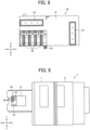
FIG. 8 is a plan view of the wiping device ofFIG. 7 ; -
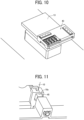
FIG. 9 is a plan view of a liquid discharge apparatus to which the wiping device ofFIG. 7 is attached, according to an embodiment of the present disclosure; -
FIG. 10 is a perspective view of the wiping device ofFIG. 7 attached to a liquid discharge apparatus according to an embodiment of the present disclosure; -
FIG. 11 is a perspective view of a positioning structure to position the wiping device ofFIG. 7 relative to a carriage, according to an embodiment of the present disclosure; -
FIGS. 12A to 12C are diagrams each illustrating an absorber of the wiping device ofFIG. 7 wiping a nozzle face and a head cover, according to an embodiment of the present disclosure; -
FIG. 13 is a perspective view of a wiping device according to another embodiment of the present disclosure; -
FIG. 14 is a side view of a web unit according to an embodiment of the present disclosure; -
FIG. 15 is a plan view of the web unit ofFIG. 14 ; and -
FIG. 16 is a diagram illustrating a web of the web unit ofFIG. 14 wiping the nozzle face and the head cover, according to an embodiment of the present disclosure. - The accompanying drawings are intended to depict embodiments of the present invention and should not be interpreted to limit the scope thereof. The accompanying drawings are not to be considered as drawn to scale unless explicitly noted. Also, identical or similar reference numerals designate identical or similar components throughout the several views.
- In describing embodiments illustrated in the drawings, specific terminology is employed for the sake of clarity. However, the disclosure of this specification is not intended to be limited to the specific terminology so selected and it is to be understood that each specific element includes all technical equivalents that have a similar function, operate in a similar manner, and achieve a similar result.
- Referring now to the drawings, embodiments of the present disclosure are described below. As used herein, the singular forms "a," "an," and "the" are intended to include the plural forms as well, unless the context clearly indicates otherwise.
- Embodiments of the present disclosure are described below with reference to the drawings. In the drawings, like reference signs denote like elements, and overlapping description may be simplified or omitted as appropriate. In the following description, a liquid discharge apparatus according to an embodiment of the present disclosure discharges a liquid onto a cloth as a recording medium.
-
FIG. 1 is a perspective view of a liquid discharge apparatus 1 according to an embodiment of the present disclosure, with covers closed, andFIG. 2 is a plan view thereof.FIG. 3 is a perspective view of the liquid discharge apparatus 1 with the covers open, andFIG. 4 is a plan view thereof. X directions inFIG. 1 are the front-rear direction, sub-scanning direction, and recording-medium conveyance direction of the liquid discharge apparatus 1 (i.e., one direction). Y directions inFIG. 1 are the lateral direction and main scanning direction of the liquid discharge apparatus 1 (i.e., another direction intersecting the one direction). Z directions inFIG. 1 are the vertical directions of the liquid discharge apparatus 1. The X directions and the Y directions are parallel to a surface, onto which a liquid is discharged, of a recording medium on aplaten 3, but may have some error. The X, Y, and Z directions are orthogonal to each other. - As illustrated in
FIGS. 1 and 2 , the liquid discharge apparatus 1 includes theplaten 3 in front of ahousing 2. Theplaten 3 is attached onto astage 13 mounted on aguide rail 4. Theplaten 3 is detachably attachable to thestage 13. Thestage 13 is a conveyor that conveys the recording medium to a liquid discharge position of the liquid discharge apparatus 1 via theplaten 3. Theguide rail 4 extends in the X directions. Acontrol panel 5 is disposed on the front face of thehousing 2. Anink cartridge 6 is detachably attached to a side face of thehousing 2. Afront cover 7 and arear cover 8 as covers are disposed over thehousing 2. - The
platen 3 has a flat upper face on which the recording medium is placed. The upper face of theplaten 3 is parallel to the X directions and the Y directions. Theplaten 3 moves on theguide rail 4 to reciprocate in both the X directions. Theplaten 3 is movable up and down in the Z directions. Thus, the height of the recording medium placed on theplaten 3 is adjustable. - The
front cover 7 and therear cover 8 are movable in both the X directions. InFIG. 1 , thefront cover 7 has been moved backward and therear cover 8 has been moved forward to close thefront cover 7 and the rear cover 8 (i.e., a closed position). On the other hand, inFIG. 3 , thefront cover 7 is moved forward and therear cover 8 is moved backward to open thefront cover 7 and the rear cover 8 (i.e., an open position). As described above, thefront cover 7 and therear cover 8 are slidably opened and closed. As a result, an occupied space of the liquid discharge apparatus 1 including an opening and closing space of each of thefront cover 7 and therear cover 8 can be reduced as compared with a configuration in which a front cover and a rear cover are opened and closed in the vertical direction. Thefront cover 7 and therear cover 8 have openings at both ends in the front-rear direction. When thefront cover 7 and therear cover 8 are closed, thefront cover 7 and therear cover 8 are continuously arranged in the front-rear direction. - As illustrated in
FIGS. 3 and 4 , anapparatus body 29 of the liquid discharge apparatus 1 includes, for example, thehousing 2 andliquid discharge units housing 2. In the present embodiment, specifically, theapparatus body 29 is a portion of the liquid discharge apparatus 1 other than thefront cover 7 and therear cover 8. Thefront cover 7 and therear cover 8 are slidable in the X directions relative to theapparatus body 29. - The
front cover 7 and therear cover 8 are opened to expose theliquid discharge units liquid discharge units front cover 7 and therear cover 8 are closed during image formation. As a result, theliquid discharge units front cover 7 and therear cover 8 to block access to operation units such as carriages of theliquid discharge units liquid discharge units front cover 7 or therear cover 8. Accordingly, a mist of ink (liquid) is prevented from scattering to environs outside the liquid discharge apparatus 1 while the liquid discharge head discharges the ink to the recording medium (i.e., during liquid discharge operation). Further, theliquid discharge units front cover 7 or therear cover 8 to collect the generated mist of the ink (i.e., ink mist) in thefront cover 7 or therear cover 8. - The liquid discharge apparatus 1 according to the present embodiment includes the two
liquid discharge units liquid discharge unit 9A discharges color ink and white ink. Theliquid discharge unit 9B discharges a pretreatment liquid. The liquid discharged by each of theliquid discharge units liquid discharge units discharge units 9Aand 9B preferably discharges the pretreatment liquid. - Since the
liquid discharge units liquid discharge unit 9A is described below. Theliquid discharge unit 9A includes acarriage 10A, aguide rod 11, and anelectrical component unit 12 including, for example, a board and an electrical component cover. A position facing thecarriage 10A or acarriage 10B in the X directions is referred to as a liquid discharge position where the liquid is discharged onto the recording medium on theplaten 3. Theliquid discharge units carriages liquid discharge unit 9 and acarriage 10, respectively, unless distinguished. - The
guide rod 11 extends in the main scanning direction. Thecarriage 10 is movable in the main scanning direction along theguide rod 11. Thecarriage 10 includes multiple liquid discharge heads. - The process of forming an image on the recording medium by the liquid discharge head is described below.
- The recording medium is placed on the
platen 3 and conveyed along theguide rail 4. The recording medium is conveyed to a rear side of the liquid discharge apparatus 1, and the pretreatment liquid is applied to the recording medium by theliquid discharge unit 9B. Specifically, while thecarriage 10B moves in the main scanning direction along theguide rod 11, theliquid discharge unit 9B discharges the pretreatment liquid from the nozzles of the liquid discharge head to apply the pretreatment liquid to the entire width of the recording medium in the main scanning direction. The application of the pretreatment liquid is repeated at multiple positions in the sub-scanning direction. Thus, the pretreatment liquid is applied to the entire recording medium. After that, theplaten 3 moves forward, and theliquid discharge unit 9A discharges the color ink of multiple colors onto the recording medium using a method similar to that of theliquid discharge unit 9B. When white color is printed on the recording medium, for example, theliquid discharge unit 9A discharges the white ink onto the recording medium, theplaten 3 moves to the rear side of theliquid discharge unit 9A again, and theliquid discharge unit 9A discharges the color ink onto the recording medium. Thus, an image is formed on the recording medium. - As illustrated in
FIG. 5 , thecarriage 10 may include multiple liquid discharge heads 20A and 20B. The multiple liquid discharge heads 20A and 20B may collectively be referred to as liquid discharge heads 20, each of which may referred to as aliquid discharge head 20 unless distinguished. In this case, for example, the pretreatment liquid is discharged by theliquid discharge head 20A, and the white or the color ink is discharged by theliquid discharge head 20B. - As illustrated in
FIG. 6 , theliquid discharge head 20 according to the present embodiment includes ahead cover 21 attached to the peripheral area of anozzle face 20a. Thehead cover 21 is disposed around theentire nozzle face 20a (seeFIG. 12 ). Thenozzle face 20a is a surface of theliquid discharge head 20 facing the recording medium. An opening end of the nozzle is formed on thenozzle face 20a. - A head maintenance device according to an embodiment of the present disclosure is described below with reference to
FIGS. 7 and8 . The head maintenance device maintains and recovers the state of theliquid discharge head 20 of the liquid discharge apparatus 1. - As illustrated in
FIGS. 7 and8 , ahead maintenance device 40 includes ahousing 41, afirst absorber 42, asecond absorber 43, and acap 44. The X, Y, and Z directions illustrated inFIG. 7 indicate the orientation of thehead maintenance device 40 attached to the liquid discharge apparatus 1 described above. Thefirst absorber 42 and thesecond absorber 43 are non-windable wipers secured on thehousing 41, and in the present embodiment, are sponges made of polyethylene. Thefirst absorber 42 and thesecond absorber 43 may be made of urethane, but not limited thereto. - Bosses of the
first absorber 42 and thesecond absorber 43 are fitted into holes of thehousing 41. Alternatively, holes of thefirst absorber 42 and thesecond absorber 43 are fitted onto bosses of thehousing 41. Thefirst absorber 42 extends in the X directions, and thesecond absorber 43 extends in the Y directions. Thefirst absorber 42 and thesecond absorber 43 move in the X directions or the Y directions relative to theliquid discharge head 20 while contacting theliquid discharge head 20 to wipe theliquid discharge head 20. Thefirst absorber 42 and thesecond absorber 43 are replaced with new ones at an appropriate point in time because the wiping performance of thefirst absorber 42 and thesecond absorber 43 deteriorates due to repeated use. At this time, the fitting of thefirst absorber 42 and thesecond absorber 43 to thehousing 41 by the bosses and the holes facilitates the replacement of thefirst absorber 42 and thesecond absorber 43. - The
cap 44 is open upward inFIG. 7 and can cover and seal thenozzle face 20a of theliquid discharge head 20. Thecap 44 filled with a cleaning liquid is kept covering thenozzle face 20a for a predetermined length of time to dissolve the thickened ink in the nozzle of theliquid discharge head 20. Thus, the clogging of the nozzle can be eliminated. Further, thecap 44 retains the moisture inside the nozzle. The same number ofcaps 44 are preferably provided for the liquid discharge heads 20 mounted on thecarriage 10, but thecap 44 may move multiple times to cover all of the liquid discharge heads 20. InFIG. 7 ,multiple caps 44 are arrayed in the Y directions, and each of themultiple caps 44 extends in the X directions. - As illustrated in
FIG. 8 , themultiple caps 44 and thesecond absorber 43 are arranged along the transverse side of thehousing 41 in the transverse direction, which is the movement direction of thehousing 41 relative to thenozzle face 20a of theliquid discharge head 20 by the stage 13 (i.e., the X directions). Thesecond absorber 43 overlaps with the multiple caps (at least one of the multiple caps 44) in the Y directions. Accordingly, themultiple caps 44 can cover the nozzles arrayed on thenozzle face 20a immediately after thesecond absorber 43 wipes thenozzle face 20a, or thesecond absorber 43 can wipe thenozzle face 20a immediately after the themultiple caps 44 separate thenozzle face 20a. - The
multiple caps 44 are disposed at one end of the longitudinal side of thehousing 41 in the Y directions, and thefirst absorber 42 is disposed at the other end of the longitudinal side of thehousing 41 in the Y directions. The longitudinal side of thehousing 41 is parallel to thesecond absorber 43. Thus, thefirst absorber 42, thesecond absorber 43, and themultiple caps 44 can be compactly arranged in thehousing 41. - The
head maintenance device 40 attached to the liquid discharge apparatus 1 is described below with reference toFIGS. 9 and10 . - As illustrated in
FIGS. 9 and10 , thehead maintenance device 40 according to the present embodiment is attached onto thestage 13 instead of the platen 3 (seeFIG. 1 ). Thestage 13 moves on theguide rail 4 to move thehead maintenance device 40 to the liquid discharge position of each of the liquid discharge heads 20A and 20B. Thestage 13 moves up and down to adjust the relative positions of theliquid discharge head 20 and thehead maintenance device 40 in the vertical direction. - The
head maintenance device 40 includes apositioning pin 45 as a positioner illustrated inFIG. 7 . As illustrated inFIG. 11 , thepositioning pin 45 is fitted into afitting hole 10a on the bottom face of thecarriage 10 to position thehead maintenance device 40 relative to thecarriage 10. Accordingly, theliquid discharge head 20 can be positioned relative to absorbers (e.g., afirst absorber 42 and a second absorber 43) and caps (e.g., caps 44) of thehead maintenance device 40. For example, when the liquid discharge apparatus 1 and thehead maintenance device 40 are shipped from a factory, thepositioning pin 45 is fitted into thefitting hole 10a, and the position of thehead maintenance device 40 relative to thecarriage 10 is stored in the liquid discharge apparatus 1. Accordingly, when thehead maintenance device 40 is used after shipment, thehead maintenance device 40 can be accurately positioned relative to theliquid discharge head 20. In particular, in the case of a large liquid discharge apparatus 1, the absolute value of the positional error between theliquid discharge head 20 and thehead maintenance device 40 is likely to be large, but the configuration according to the present embodiment can position thehead maintenance device 40 relative to theliquid discharge head 20 with high accuracy. - The
first absorber 42 and thesecond absorber 43 wiping theliquid discharge head 20 are described below. - The
stage 13 moves on the guide rail 4 (seeFIG. 1 ), and the carriage 10 (seeFIG. 4 ) moves in the main scanning direction to cause thehead maintenance device 40 to face thecarriage 10. Then, thestage 13 moves upward to bring thefirst absorber 42 or thesecond absorber 43 into contact with theliquid discharge head 20. -
FIGS. 12Ato 12C are diagrams each illustrating theliquid discharge head 20 which is wiped by thefirst absorber 42 or thesecond absorber 43 as viewed from the bottom face side of thecarriage 10. - As illustrated in
FIG. 12A , as thestage 13 reciprocally moves in the X directions, thefirst absorber 42 reciprocates in the X directions between the liquid discharge heads 20 while contacting the liquid discharge heads 20. Thus, thefirst absorber 42 can wipe the peripheral area of thehead cover 21 extending in the X directions. Thefirst absorber 42 reciprocates twice at five positions in total including three positions between the liquid discharge heads 20, the left side of the leftmostliquid discharge head 20 inFIG. 12A , and the right side of the rightmostliquid discharge head 20 inFIG. 12A . Thus, thefirst absorber 42 reciprocates ten times in total to wipe the peripheral area extending in the X directions of all the liquid discharge heads 20. - As illustrated in
FIG. 12B , thesecond absorber 43 contacts one end of the liquid discharge heads 20 in the X directions. As thestage 13 moves, thesecond absorber 43 moves in one of the X directions while contacting the liquid discharge heads 20. Accordingly, thesecond absorber 43 can wipe the entire bottom faces of the liquid discharge heads 20 including the nozzle faces 20a of the liquid discharge heads 20 in one wiping. - Further, as illustrated in
FIG. 12C , thesecond absorber 43 contacts one end or the other end of the liquid discharge heads 20 in the X directions. As thecarriage 10 moves along the guide rod 11 (seeFIG. 4 ), thesecond absorber 43 moves in the Y directions relative to the liquid discharge heads 20 while contacting the one end or the other end of the liquid discharge heads 20. Specifically, thesecond absorber 43 reciprocates in the Y directions four times at the one end or the other end of the liquid discharge heads 20 in the X directions. Thus, thesecond absorber 43 can wipe the peripheral area of thehead cover 21 extending in the Y directions. - The liquid discharge heads 20 can be wiped by the
first absorber 42 and thesecond absorber 43 by the above operations. The movement of thestage 13 in the X directions and the movement of thecarriage 10 in the Y directions cause thefirst absorber 42 or thesecond absorber 43 to contact the liquid discharge heads 20 and reciprocally move relative to the liquid discharge heads 20 as described above. - The
head maintenance device 40 is arranged at a predetermined position relative to thecarriage 10 by the movement of thestage 13 or the movement of thecarriage 10 so that the caps 44 (seeFIG. 7 ) face the liquid discharge heads 20. Under these conditions, thestage 13 moves upward to cause thecaps 44 to cover the nozzle faces 20a of the liquid discharge heads 20. Thus, the clogging of the nozzles of theliquid discharge head 20 can be eliminated as described above. - As described above, in the present embodiment, due to such a configuration in which the
head maintenance device 40 is attached to thestage 13, a head maintenance device is not necessarily accommodated in the liquid discharge apparatus 1, so that the liquid discharge apparatus 1 can be downsized. Thehead maintenance device 40 can perform the wiping operation of the liquid discharge heads 20 and the capping operation with respect to the nozzle faces 20a of the liquid discharge heads 20. Accordingly, the nozzles of theliquid discharge head 20 can be maintained and recovered by onehead maintenance device 40. In addition, due to such a configuration in which thehead maintenance device 40 is attached to thestage 13, the wiping operation and the capping operation described above can be performed using the movement of thestage 13 in the X directions and the movement of thecarriage 10 in the Y directions. Accordingly, the nozzles of theliquid discharge head 20 can be maintained and recovered without another driving mechanism. - A
head maintenance device 40 according to a modification of the present embodiment is described below. - The
head maintenance device 40 illustrated inFIG. 13 is different in that aweb unit 46 including awindable web 51 is provided instead of the above-described absorbers (e.g., thefirst absorber 42 and the second absorber 43). - As illustrated in
FIG. 14 , theweb unit 46 includes theweb 51 as a wiper, afeed roller 52, a take-uproller 53, guiderollers member 56, aspring 57, adrive motor 58, and atransmission mechanism 59. Theweb 51 is wound around the outer circumferential surface of thefeed roller 52 to form aroll 51A of theweb 51 to be fed. Theweb 51 is wound around the outer circumferential surface of the take-uproller 53 to form aroll 51B of thewound web 51. Theweb 51 is fed in the direction indicated by arrow A. InFIG. 14 , the illustration of thehead cover 21 of theliquid discharge head 20 is omitted. Thefeed roller 52, the take-uproller 53, and theguide rollers FIG. 15 ) in the housing 41 (seeFIG. 13 ) of thehead maintenance device 40. The upper portion of theweb unit 46 inFIG. 14 corresponds to theweb unit 46 illustrated inFIG. 13 , and the lower portion of theweb unit 46 inFIG. 14 is accommodated in thehousing 41 of thehead maintenance device 40. In other words, the lower portion of theweb unit 46 is covered by thehousing 41 inFIG. 13 . - The
spring 57 presses the pressingmember 56 between theguide rollers member 56 to press theweb 51 against thenozzle face 20a to be wiped. The portion of theweb 51 pressed against thenozzle face 20a by the pressingmember 56 is a wipingportion 51a of theweb 51. - Preferably, the
web 51 is a sheet-shaped material that has absorbency and liquid resistance, at least, against the liquid to be used and does not cause fuzz and dust. Examples of such materials include, but are not limited to, nonwoven fabric, cloth, film, and paper. - The driving force of the
drive motor 58 is transmitted to the take-uproller 53 via thetransmission mechanism 59. The take-uproller 53 is rotated by the driving force of thedrive motor 58 to wind and convey theweb 51 in the direction indicated by arrow A. - A
code wheel 61 is attached to theguide roller 54, and anencoder sensor 62 including a transmissive photosensor detects a pattern formed on thecode wheel 61. Thecode wheel 61 and theencoder sensor 62 together serve as anencoder 63 that detects the distance of movement (feed amount) of theweb 51. When the end state (i.e., depletion) of theweb 51 is detected by theencoder 63 based on the feed amount, theweb 51 is replaced with a new one. - As illustrated in
FIG. 16 , thestage 13 reciprocally moves in the X directions at multiple positions in the Y directions while the wipingportion 51a of theweb 51 is pressed against theliquid discharge head 20 to wipe theentire nozzle face 20a and thehead cover 21. In addition, thecaps 44 can perform the capping operation with respect to thenozzle face 20a of theliquid discharge head 20. As described above, the nozzles of theliquid discharge head 20 can be maintained and recovered by thehead maintenance device 40 according to the present embodiment. Further, theweb unit 46 may include an absorber in addition to theweb 51. - Note that numerous additional modifications and variations are possible in light of the above teachings. It is therefore to be understood that within the scope of the appended claims, the embodiments of the present disclosure may be practiced otherwise than as specifically described herein. For example, elements and/or features of different illustrative embodiments may be combined with each other and/or substituted for each other within the scope of this disclosure and appended claims.
- In the present disclosure, the liquid to be discharged is not limited to a particular liquid as long as the liquid has a viscosity or surface tension to be discharged from a head (liquid discharge head). However, preferably, the viscosity of the liquid is not greater than 30 millipascal-second (mPa·s) under ordinary temperature and ordinary pressure or by heating or cooling. Examples of the liquid to be discharged include a solution, a suspension, or an emulsion including, for example, a solvent, such as water or an organic solvent; a colorant, such as dye or pigment; a functional material, such as a polymerizable compound, a resin, or a surfactant; a biocompatible material, such as deoxyribonucleic acid (DNA), amino acid, protein, or calcium; and an edible material, such as a natural colorant. Such a solution, a suspension, or an emulsion can be used for, e.g., inkjet ink; surface treatment liquid; a liquid for forming an electronic element component, a light-emitting element component, or an electronic circuit resist pattern; or a material solution for three-dimensional fabrication.
- The term "liquid" includes not only ink but also paint, a pretreatment liquid, a binder, and an overcoat liquid.
- In the present disclosure, the term "liquid discharge apparatus" includes a carriage including a liquid discharge head and drives the liquid discharge head to discharge liquid. The term "liquid discharge apparatus" used in the present disclosure includes, in addition to apparatuses to discharge liquid to a recording medium serving as a medium onto which liquid can adhere, apparatuses to discharge the liquid into gas (air) or liquid.
- For example, the "liquid discharge apparatus" may further include devices relating to feeding, conveying, and ejecting of the medium onto which liquid can adhere and also include a pretreatment device and an aftertreatment device.
- The "liquid discharge apparatus" may be, for example, an image forming apparatus to form an image on a sheet by discharging ink, or a three-dimensional fabrication apparatus to discharge fabrication liquid to a powder layer in which powder material is formed in layers to form a three-dimensional object.
- The "liquid discharge apparatus" is not limited to an apparatus that discharges liquid to visualize meaningful images such as characters or figures. For example, the liquid discharge apparatus may be an apparatus that forms patterns having no meaning or an apparatus that fabricates three-dimensional images.
- The above-described term "medium onto which liquid can adhere" represents a medium on which liquid is at least temporarily adhered, a medium on which liquid is adhered and fixed, or a medium into which liquid adheres and permeates. Specific examples of the "medium onto which liquid can adhere" include, but are not limited to, a recording medium such as a paper sheet, recording paper, a recording sheet of paper, a film, or cloth, an electronic component such as an electronic substrate or a piezoelectric element, and a medium such as layered powder, an organ model, or a testing cell. The "medium onto which liquid can adhere" includes any material to which liquid adheres, unless otherwise specified.
- Examples of materials of the "medium onto which liquid can adhere" include any materials to which liquid can adhere even temporarily, such as paper, thread, fiber, fabric, leather, metal, plastic, glass, wood, and ceramic.
- The term "liquid discharge apparatus" may be an apparatus in which the liquid discharge head and the medium onto which liquid can adhere move relative to each other. However, the liquid discharge apparatus is not limited to such an apparatus. For example, the liquid discharge apparatus may be a serial head apparatus that moves the liquid discharge head or a line head apparatus that does not move the liquid discharge head.
- Examples of the liquid discharge apparatus further include: a treatment liquid applying apparatus that discharges a treatment liquid onto a sheet to apply the treatment liquid to the surface of the sheet, for reforming the surface of the sheet; and an injection granulation apparatus that injects a composition liquid, in which a raw material is dispersed in a solution, through a nozzle to granulate fine particle of the raw material.
- The terms "image formation," "recording," "printing," "image printing," and "fabricating" used in the present disclosure may be used synonymously with each other.
- Aspects of the present disclosure are, for example, as follows.
- A head maintenance device includes a wiper to wipe a liquid discharge head, and a cap to cover a nozzle face. The nozzle face is a surface of the liquid discharge head and has an opening end of a nozzle. The head maintenance device is detachably attachable to a conveyor to convey a recording medium to a liquid discharge position.
- In other words, a head maintenance device includes a housing, a wiper, and a cap. The housing is detachably attachable to a conveyor of the liquid discharge apparatus. The conveyor conveys a medium in one direction. The wiper is disposed in the housing to wipe a nozzle face of a liquid discharge head of the liquid discharge apparatus. The cap is disposed in the housing to cover nozzles arrayed on the nozzle face of the liquid discharge head in the one direction.
- In the head maintenance device according to Aspect 1, the wiper extends in another direction intersecting the one direction in the housing, and the cap extends in the one direction in the housing.
- In the head maintenance device according to
Aspect 2, the wiper and the cap in the housing are along a moving direction of the housing relative to the nozzle face of the liquid discharge head. - The head maintenance device according to
Aspect 3, further includes multiple caps including the cap. The multiple caps are arrayed in said another direction, and the wiper overlaps with the multiple caps in said another direction. - In the head maintenance device according to
Aspect 2, the housing has a longitudinal side in said another direction parallel to the wiper. - In the head maintenance device according to any one of Aspects 1 to 5, the wiper is a non-windable absorber.
- In other words, the wiper includes an absorber secured on the housing.
- In the head maintenance device according to
Aspect 6, the absorber has a hole, and the housing has a boss fittable into the hole. - In the head maintenance device according to
Aspect 6, the housing has a hole, and the absorber has a boss fittable into the hole. - In the head maintenance device according to any one of
Aspects 1 or 5, the wiper is windable. - In other words, the wiper includes windable web.
- The head maintenance device according to any one of Aspects 1 to 9, further includes a positioner that can be positioned relative to a carriage including the liquid discharge head.
- In other words, the head maintenance device according to any one of Aspects 1 to 9, further includes a positioner to position the housing relative to a carriage mounting the liquid discharge head.
- The head maintenance device according to
Aspect 2, further includes another wiper extending in the one direction in the housing. The housing has a longitudinal side in said another direction parallel to the wiper. The cap is disposed at one end of the longitudinal side of the housing, and said another wiper is disposed at another end of the longitudinal side of the housing. - A liquid discharge apparatus includes the head maintenance device according to any one of Aspects 1 to 11, the liquid discharge head, and the conveyor.
- In other words, a liquid discharge apparatus includes the head maintenance device according to any one of Aspects 1 to 11, the liquid discharge head to discharge a liquid onto the medium, and the conveyor to convey the medium to the liquid discharge head.
Claims (12)
- A head maintenance device (40) comprising:a housing (41) detachably attachable to a conveyor (13) of a liquid discharge apparatus (1), the conveyor (13) to convey a medium in one direction;a wiper (43) in the housing (41) to wipe a nozzle face (20a) of a liquid discharge head (20) of the liquid discharge apparatus (1); anda cap (44) in the housing (41) to cover nozzles arrayed on the nozzle face (20a) of the liquid discharge head (20) in the one direction.
- The head maintenance device (40) according to claim 1,wherein the wiper (43) extends in another direction intersecting the one direction in the housing (41); andthe cap (44) extends in the one direction in the housing (41).
- The head maintenance device (40) according to claim 2,
wherein the wiper (43) and the cap (44) in the housing (41) are along a moving direction of the housing (41) relative to the nozzle face (20a) of the liquid discharge head (20). - The head maintenance device (40) according to claim 3, further comprising multiple caps (44) including the cap (44),wherein the multiple caps (44) are arrayed in said another direction, andthe wiper (43) overlaps with the multiple caps (44) in said another direction.
- The head maintenance device (40) according to claim 2,
wherein the housing (41) has a longitudinal side in said another direction parallel to the wiper (43). - The head maintenance device (40) according to any one of claims 1 to 5, wherein the wiper (43) includes an absorber secured on the housing (41).
- The head maintenance device (40) according to claim 6,wherein the absorber has a hole, andthe housing (41) has a boss fittable into the hole.
- The head maintenance device (40) according to claim 6,wherein the housing (41) has a hole; andthe absorber has a boss fittable into the hole.
- The head maintenance device (40) according to any one of claims 1 to 5, wherein the wiper (43) includes windable web (51).
- The head maintenance device (40) according to any one of claims 1 to 9, further comprising a positioner (45) to position the housing (41) relative to a carriage (10) mounting the liquid discharge head (20).
- The head maintenance device (40) according to claim 2, further comprising another wiper (42) extending in the one direction in the housing (41),wherein the housing (41) has a longitudinal side in said another direction parallel to the wiper (43),the cap (44) is at one end of the longitudinal side of the housing (41), andsaid another wiper (42) is at another end of the longitudinal side of the housing (41).
- A liquid discharge apparatus (1) comprising:the head maintenance device (40) according to any one of claims 1 to 11;the liquid discharge head (20) to discharge a liquid onto the medium; andthe conveyor (13) to convey the medium to the liquid discharge head (20).
Applications Claiming Priority (1)
| Application Number | Priority Date | Filing Date | Title |
|---|---|---|---|
| JP2023048096A JP2024136824A (en) | 2023-03-24 | 2023-03-24 | Head maintenance device, liquid ejection device |
Publications (2)
| Publication Number | Publication Date |
|---|---|
| EP4434754A1 true EP4434754A1 (en) | 2024-09-25 |
| EP4434754B1 EP4434754B1 (en) | 2025-07-16 |
Family
ID=90363398
Family Applications (1)
| Application Number | Title | Priority Date | Filing Date |
|---|---|---|---|
| EP24162252.1A Active EP4434754B1 (en) | 2023-03-24 | 2024-03-08 | Head maintenance device and liquid discharge apparatus |
Country Status (3)
| Country | Link |
|---|---|
| US (1) | US20240316935A1 (en) |
| EP (1) | EP4434754B1 (en) |
| JP (1) | JP2024136824A (en) |
Citations (3)
| Publication number | Priority date | Publication date | Assignee | Title |
|---|---|---|---|---|
| US20070263029A1 (en) * | 2006-05-11 | 2007-11-15 | Brother Kogyo Kabushiki Kaisha | Ink-jet recording apparatus |
| US20130120496A1 (en) * | 2011-11-11 | 2013-05-16 | Seiko Epson Corporation | Wiper unit and liquid ejecting apparatus |
| JP2022140297A (en) | 2021-03-10 | 2022-09-26 | 株式会社リコー | Liquid discharge device, head maintenance method, and head cleaning jig |
Family Cites Families (6)
| Publication number | Priority date | Publication date | Assignee | Title |
|---|---|---|---|---|
| JP2005254636A (en) * | 2004-03-12 | 2005-09-22 | Ricoh Co Ltd | Image forming apparatus |
| JP5139909B2 (en) * | 2008-07-28 | 2013-02-06 | 株式会社リコー | Image forming apparatus |
| JP6746954B2 (en) * | 2016-03-01 | 2020-08-26 | 株式会社リコー | Device for ejecting liquid |
| US11292258B2 (en) * | 2019-11-29 | 2022-04-05 | Ricoh Company, Ltd. | Head cleaner, liquid discharge apparatus, and head cleaning method |
| DE102021110417A1 (en) * | 2021-04-23 | 2022-10-27 | Canon Production Printing Holding B.V. | Ink printer and method for printing a web-shaped recording medium |
| JP2022184243A (en) * | 2021-05-31 | 2022-12-13 | ブラザー工業株式会社 | Printing apparatus and absorber |
-
2023
- 2023-03-24 JP JP2023048096A patent/JP2024136824A/en active Pending
-
2024
- 2024-03-01 US US18/592,535 patent/US20240316935A1/en active Pending
- 2024-03-08 EP EP24162252.1A patent/EP4434754B1/en active Active
Patent Citations (3)
| Publication number | Priority date | Publication date | Assignee | Title |
|---|---|---|---|---|
| US20070263029A1 (en) * | 2006-05-11 | 2007-11-15 | Brother Kogyo Kabushiki Kaisha | Ink-jet recording apparatus |
| US20130120496A1 (en) * | 2011-11-11 | 2013-05-16 | Seiko Epson Corporation | Wiper unit and liquid ejecting apparatus |
| JP2022140297A (en) | 2021-03-10 | 2022-09-26 | 株式会社リコー | Liquid discharge device, head maintenance method, and head cleaning jig |
Also Published As
| Publication number | Publication date |
|---|---|
| US20240316935A1 (en) | 2024-09-26 |
| JP2024136824A (en) | 2024-10-04 |
| EP4434754B1 (en) | 2025-07-16 |
Similar Documents
| Publication | Publication Date | Title |
|---|---|---|
| US10350895B2 (en) | Head cleaner and liquid discharge apparatus | |
| US9789692B2 (en) | Liquid ejecting apparatus and cleaning device | |
| US10226929B2 (en) | Head cleaner, maintenance device, and liquid discharge apparatus | |
| US10543689B2 (en) | Liquid discharge apparatus | |
| CN114103461B (en) | Nozzle cap device, liquid ejecting apparatus, and nozzle cap method | |
| US11427001B2 (en) | Head maintenance device, liquid discharge apparatus, and printer | |
| US20240173982A1 (en) | Inkjet nozzles cleaning in a digital printing system | |
| EP4434754B1 (en) | Head maintenance device and liquid discharge apparatus | |
| JP7651979B2 (en) | Head cap device, liquid ejection device, and head capping method | |
| US20250178357A1 (en) | Liquid discharge apparatus | |
| JP2021146529A (en) | Device for discharging liquid | |
| JP7106877B2 (en) | Cleaning device for liquid ejection head and device for ejecting liquid | |
| EP4344889B1 (en) | Liquid discharge apparatus | |
| US20240326442A1 (en) | Wiping device and liquid discharge apparatus | |
| US12552171B2 (en) | Printer | |
| US20240316588A1 (en) | Wiping device and liquid discharge apparatus | |
| US20240326448A1 (en) | Liquid discharge apparatus | |
| US20240391249A1 (en) | Liquid discharge apparatus and printing method | |
| EP4344885A1 (en) | Liquid discharge apparatus | |
| US20240181783A1 (en) | Wiping device, head maintenance device, and liquid discharge apparatus | |
| US12496841B2 (en) | Liquid discharge apparatus | |
| US12157316B2 (en) | Nozzle surface recovery device, liquid discharge device, and inkjet printer | |
| CN116981572A (en) | Cleaning of inkjet nozzles in digital printing systems | |
| US20240316934A1 (en) | Wiping device and liquid discharge apparatus | |
| JP7483559B2 (en) | Inkjet recording device |
Legal Events
| Date | Code | Title | Description |
|---|---|---|---|
| PUAI | Public reference made under article 153(3) epc to a published international application that has entered the european phase |
Free format text: ORIGINAL CODE: 0009012 |
|
| STAA | Information on the status of an ep patent application or granted ep patent |
Free format text: STATUS: REQUEST FOR EXAMINATION WAS MADE |
|
| 17P | Request for examination filed |
Effective date: 20240308 |
|
| AK | Designated contracting states |
Kind code of ref document: A1 Designated state(s): AL AT BE BG CH CY CZ DE DK EE ES FI FR GB GR HR HU IE IS IT LI LT LU LV MC ME MK MT NL NO PL PT RO RS SE SI SK SM TR |
|
| GRAP | Despatch of communication of intention to grant a patent |
Free format text: ORIGINAL CODE: EPIDOSNIGR1 |
|
| STAA | Information on the status of an ep patent application or granted ep patent |
Free format text: STATUS: GRANT OF PATENT IS INTENDED |
|
| RIC1 | Information provided on ipc code assigned before grant |
Ipc: B41J 2/165 20060101AFI20250219BHEP |
|
| INTG | Intention to grant announced |
Effective date: 20250313 |
|
| GRAS | Grant fee paid |
Free format text: ORIGINAL CODE: EPIDOSNIGR3 |
|
| GRAA | (expected) grant |
Free format text: ORIGINAL CODE: 0009210 |
|
| STAA | Information on the status of an ep patent application or granted ep patent |
Free format text: STATUS: THE PATENT HAS BEEN GRANTED |
|
| P01 | Opt-out of the competence of the unified patent court (upc) registered |
Free format text: CASE NUMBER: APP_25950/2025 Effective date: 20250602 |
|
| AK | Designated contracting states |
Kind code of ref document: B1 Designated state(s): AL AT BE BG CH CY CZ DE DK EE ES FI FR GB GR HR HU IE IS IT LI LT LU LV MC ME MK MT NL NO PL PT RO RS SE SI SK SM TR |
|
| REG | Reference to a national code |
Ref country code: GB Ref legal event code: FG4D |
|
| REG | Reference to a national code |
Ref country code: CH Ref legal event code: EP Ref country code: DE Ref legal event code: R096 Ref document number: 602024000299 Country of ref document: DE |
|
| REG | Reference to a national code |
Ref country code: IE Ref legal event code: FG4D |
|
| REG | Reference to a national code |
Ref country code: NL Ref legal event code: MP Effective date: 20250716 |
|
| PG25 | Lapsed in a contracting state [announced via postgrant information from national office to epo] |
Ref country code: PT Free format text: LAPSE BECAUSE OF FAILURE TO SUBMIT A TRANSLATION OF THE DESCRIPTION OR TO PAY THE FEE WITHIN THE PRESCRIBED TIME-LIMIT Effective date: 20251117 |
|
| PG25 | Lapsed in a contracting state [announced via postgrant information from national office to epo] |
Ref country code: NL Free format text: LAPSE BECAUSE OF FAILURE TO SUBMIT A TRANSLATION OF THE DESCRIPTION OR TO PAY THE FEE WITHIN THE PRESCRIBED TIME-LIMIT Effective date: 20250716 |
|
| REG | Reference to a national code |
Ref country code: AT Ref legal event code: MK05 Ref document number: 1813711 Country of ref document: AT Kind code of ref document: T Effective date: 20250716 |
|
| PG25 | Lapsed in a contracting state [announced via postgrant information from national office to epo] |
Ref country code: IS Free format text: LAPSE BECAUSE OF FAILURE TO SUBMIT A TRANSLATION OF THE DESCRIPTION OR TO PAY THE FEE WITHIN THE PRESCRIBED TIME-LIMIT Effective date: 20251116 |
|
| PG25 | Lapsed in a contracting state [announced via postgrant information from national office to epo] |
Ref country code: NO Free format text: LAPSE BECAUSE OF FAILURE TO SUBMIT A TRANSLATION OF THE DESCRIPTION OR TO PAY THE FEE WITHIN THE PRESCRIBED TIME-LIMIT Effective date: 20251016 |
|
| REG | Reference to a national code |
Ref country code: LT Ref legal event code: MG9D |
|
| PG25 | Lapsed in a contracting state [announced via postgrant information from national office to epo] |
Ref country code: AT Free format text: LAPSE BECAUSE OF FAILURE TO SUBMIT A TRANSLATION OF THE DESCRIPTION OR TO PAY THE FEE WITHIN THE PRESCRIBED TIME-LIMIT Effective date: 20250716 |
|
| PG25 | Lapsed in a contracting state [announced via postgrant information from national office to epo] |
Ref country code: FI Free format text: LAPSE BECAUSE OF FAILURE TO SUBMIT A TRANSLATION OF THE DESCRIPTION OR TO PAY THE FEE WITHIN THE PRESCRIBED TIME-LIMIT Effective date: 20250716 |
|
| PG25 | Lapsed in a contracting state [announced via postgrant information from national office to epo] |
Ref country code: HR Free format text: LAPSE BECAUSE OF FAILURE TO SUBMIT A TRANSLATION OF THE DESCRIPTION OR TO PAY THE FEE WITHIN THE PRESCRIBED TIME-LIMIT Effective date: 20250716 |
|
| PG25 | Lapsed in a contracting state [announced via postgrant information from national office to epo] |
Ref country code: GR Free format text: LAPSE BECAUSE OF FAILURE TO SUBMIT A TRANSLATION OF THE DESCRIPTION OR TO PAY THE FEE WITHIN THE PRESCRIBED TIME-LIMIT Effective date: 20251017 |
|
| PG25 | Lapsed in a contracting state [announced via postgrant information from national office to epo] |
Ref country code: SE Free format text: LAPSE BECAUSE OF FAILURE TO SUBMIT A TRANSLATION OF THE DESCRIPTION OR TO PAY THE FEE WITHIN THE PRESCRIBED TIME-LIMIT Effective date: 20250716 |
|
| PG25 | Lapsed in a contracting state [announced via postgrant information from national office to epo] |
Ref country code: LV Free format text: LAPSE BECAUSE OF FAILURE TO SUBMIT A TRANSLATION OF THE DESCRIPTION OR TO PAY THE FEE WITHIN THE PRESCRIBED TIME-LIMIT Effective date: 20250716 |
|
| PG25 | Lapsed in a contracting state [announced via postgrant information from national office to epo] |
Ref country code: PL Free format text: LAPSE BECAUSE OF FAILURE TO SUBMIT A TRANSLATION OF THE DESCRIPTION OR TO PAY THE FEE WITHIN THE PRESCRIBED TIME-LIMIT Effective date: 20250716 Ref country code: BG Free format text: LAPSE BECAUSE OF FAILURE TO SUBMIT A TRANSLATION OF THE DESCRIPTION OR TO PAY THE FEE WITHIN THE PRESCRIBED TIME-LIMIT Effective date: 20250716 |
|
| PG25 | Lapsed in a contracting state [announced via postgrant information from national office to epo] |
Ref country code: RS Free format text: LAPSE BECAUSE OF FAILURE TO SUBMIT A TRANSLATION OF THE DESCRIPTION OR TO PAY THE FEE WITHIN THE PRESCRIBED TIME-LIMIT Effective date: 20251016 |
|
| PG25 | Lapsed in a contracting state [announced via postgrant information from national office to epo] |
Ref country code: ES Free format text: LAPSE BECAUSE OF FAILURE TO SUBMIT A TRANSLATION OF THE DESCRIPTION OR TO PAY THE FEE WITHIN THE PRESCRIBED TIME-LIMIT Effective date: 20250716 |
|
| PG25 | Lapsed in a contracting state [announced via postgrant information from national office to epo] |
Ref country code: SM Free format text: LAPSE BECAUSE OF FAILURE TO SUBMIT A TRANSLATION OF THE DESCRIPTION OR TO PAY THE FEE WITHIN THE PRESCRIBED TIME-LIMIT Effective date: 20250716 |
|
| PG25 | Lapsed in a contracting state [announced via postgrant information from national office to epo] |
Ref country code: DK Free format text: LAPSE BECAUSE OF FAILURE TO SUBMIT A TRANSLATION OF THE DESCRIPTION OR TO PAY THE FEE WITHIN THE PRESCRIBED TIME-LIMIT Effective date: 20250716 |
|
| PGFP | Annual fee paid to national office [announced via postgrant information from national office to epo] |
Ref country code: DE Payment date: 20260319 Year of fee payment: 3 |
|
| PG25 | Lapsed in a contracting state [announced via postgrant information from national office to epo] |
Ref country code: IT Free format text: LAPSE BECAUSE OF FAILURE TO SUBMIT A TRANSLATION OF THE DESCRIPTION OR TO PAY THE FEE WITHIN THE PRESCRIBED TIME-LIMIT Effective date: 20250716 |
|
| PGFP | Annual fee paid to national office [announced via postgrant information from national office to epo] |
Ref country code: FR Payment date: 20260323 Year of fee payment: 3 |
|
| PG25 | Lapsed in a contracting state [announced via postgrant information from national office to epo] |
Ref country code: CZ Free format text: LAPSE BECAUSE OF FAILURE TO SUBMIT A TRANSLATION OF THE DESCRIPTION OR TO PAY THE FEE WITHIN THE PRESCRIBED TIME-LIMIT Effective date: 20250716 |
|
| PG25 | Lapsed in a contracting state [announced via postgrant information from national office to epo] |
Ref country code: EE Free format text: LAPSE BECAUSE OF FAILURE TO SUBMIT A TRANSLATION OF THE DESCRIPTION OR TO PAY THE FEE WITHIN THE PRESCRIBED TIME-LIMIT Effective date: 20250716 Ref country code: SK Free format text: LAPSE BECAUSE OF FAILURE TO SUBMIT A TRANSLATION OF THE DESCRIPTION OR TO PAY THE FEE WITHIN THE PRESCRIBED TIME-LIMIT Effective date: 20250716 |