EP4434730A1 - Battery case sealing device and battery case sealing method using same - Google Patents
Battery case sealing device and battery case sealing method using same Download PDFInfo
- Publication number
- EP4434730A1 EP4434730A1 EP22911885.6A EP22911885A EP4434730A1 EP 4434730 A1 EP4434730 A1 EP 4434730A1 EP 22911885 A EP22911885 A EP 22911885A EP 4434730 A1 EP4434730 A1 EP 4434730A1
- Authority
- EP
- European Patent Office
- Prior art keywords
- battery case
- sealing
- primarily
- heating
- unit
- Prior art date
- Legal status (The legal status is an assumption and is not a legal conclusion. Google has not performed a legal analysis and makes no representation as to the accuracy of the status listed.)
- Pending
Links
Images


Classifications
-
- H—ELECTRICITY
- H01—ELECTRIC ELEMENTS
- H01M—PROCESSES OR MEANS, e.g. BATTERIES, FOR THE DIRECT CONVERSION OF CHEMICAL ENERGY INTO ELECTRICAL ENERGY
- H01M50/00—Constructional details or processes of manufacture of the non-active parts of electrochemical cells other than fuel cells, e.g. hybrid cells
- H01M50/10—Primary casings; Jackets or wrappings
- H01M50/102—Primary casings; Jackets or wrappings characterised by their shape or physical structure
- H01M50/105—Pouches or flexible bags
-
- B—PERFORMING OPERATIONS; TRANSPORTING
- B29—WORKING OF PLASTICS; WORKING OF SUBSTANCES IN A PLASTIC STATE IN GENERAL
- B29C—SHAPING OR JOINING OF PLASTICS; SHAPING OF MATERIAL IN A PLASTIC STATE, NOT OTHERWISE PROVIDED FOR; AFTER-TREATMENT OF THE SHAPED PRODUCTS, e.g. REPAIRING
- B29C65/00—Joining or sealing of preformed parts, e.g. welding of plastics materials; Apparatus therefor
- B29C65/02—Joining or sealing of preformed parts, e.g. welding of plastics materials; Apparatus therefor by heating, with or without pressure
- B29C65/14—Joining or sealing of preformed parts, e.g. welding of plastics materials; Apparatus therefor by heating, with or without pressure using wave energy, i.e. electromagnetic radiation, or particle radiation
-
- B—PERFORMING OPERATIONS; TRANSPORTING
- B29—WORKING OF PLASTICS; WORKING OF SUBSTANCES IN A PLASTIC STATE IN GENERAL
- B29C—SHAPING OR JOINING OF PLASTICS; SHAPING OF MATERIAL IN A PLASTIC STATE, NOT OTHERWISE PROVIDED FOR; AFTER-TREATMENT OF THE SHAPED PRODUCTS, e.g. REPAIRING
- B29C66/00—General aspects of processes or apparatus for joining preformed parts
- B29C66/01—General aspects dealing with the joint area or with the area to be joined
- B29C66/02—Preparation of the material, in the area to be joined, prior to joining or welding
- B29C66/024—Thermal pre-treatments
-
- B—PERFORMING OPERATIONS; TRANSPORTING
- B29—WORKING OF PLASTICS; WORKING OF SUBSTANCES IN A PLASTIC STATE IN GENERAL
- B29C—SHAPING OR JOINING OF PLASTICS; SHAPING OF MATERIAL IN A PLASTIC STATE, NOT OTHERWISE PROVIDED FOR; AFTER-TREATMENT OF THE SHAPED PRODUCTS, e.g. REPAIRING
- B29C66/00—General aspects of processes or apparatus for joining preformed parts
- B29C66/01—General aspects dealing with the joint area or with the area to be joined
- B29C66/02—Preparation of the material, in the area to be joined, prior to joining or welding
- B29C66/024—Thermal pre-treatments
- B29C66/0242—Heating, or preheating, e.g. drying
-
- B—PERFORMING OPERATIONS; TRANSPORTING
- B29—WORKING OF PLASTICS; WORKING OF SUBSTANCES IN A PLASTIC STATE IN GENERAL
- B29C—SHAPING OR JOINING OF PLASTICS; SHAPING OF MATERIAL IN A PLASTIC STATE, NOT OTHERWISE PROVIDED FOR; AFTER-TREATMENT OF THE SHAPED PRODUCTS, e.g. REPAIRING
- B29C66/00—General aspects of processes or apparatus for joining preformed parts
- B29C66/01—General aspects dealing with the joint area or with the area to be joined
- B29C66/03—After-treatments in the joint area
- B29C66/034—Thermal after-treatments
-
- B—PERFORMING OPERATIONS; TRANSPORTING
- B29—WORKING OF PLASTICS; WORKING OF SUBSTANCES IN A PLASTIC STATE IN GENERAL
- B29C—SHAPING OR JOINING OF PLASTICS; SHAPING OF MATERIAL IN A PLASTIC STATE, NOT OTHERWISE PROVIDED FOR; AFTER-TREATMENT OF THE SHAPED PRODUCTS, e.g. REPAIRING
- B29C66/00—General aspects of processes or apparatus for joining preformed parts
- B29C66/01—General aspects dealing with the joint area or with the area to be joined
- B29C66/05—Particular design of joint configurations
- B29C66/10—Particular design of joint configurations particular design of the joint cross-sections
- B29C66/11—Joint cross-sections comprising a single joint-segment, i.e. one of the parts to be joined comprising a single joint-segment in the joint cross-section
- B29C66/112—Single lapped joints
- B29C66/1122—Single lap to lap joints, i.e. overlap joints
-
- B—PERFORMING OPERATIONS; TRANSPORTING
- B29—WORKING OF PLASTICS; WORKING OF SUBSTANCES IN A PLASTIC STATE IN GENERAL
- B29C—SHAPING OR JOINING OF PLASTICS; SHAPING OF MATERIAL IN A PLASTIC STATE, NOT OTHERWISE PROVIDED FOR; AFTER-TREATMENT OF THE SHAPED PRODUCTS, e.g. REPAIRING
- B29C66/00—General aspects of processes or apparatus for joining preformed parts
- B29C66/01—General aspects dealing with the joint area or with the area to be joined
- B29C66/345—Progressively making the joint, e.g. starting from the middle
- B29C66/3452—Making complete joints by combining partial joints
-
- B—PERFORMING OPERATIONS; TRANSPORTING
- B29—WORKING OF PLASTICS; WORKING OF SUBSTANCES IN A PLASTIC STATE IN GENERAL
- B29C—SHAPING OR JOINING OF PLASTICS; SHAPING OF MATERIAL IN A PLASTIC STATE, NOT OTHERWISE PROVIDED FOR; AFTER-TREATMENT OF THE SHAPED PRODUCTS, e.g. REPAIRING
- B29C66/00—General aspects of processes or apparatus for joining preformed parts
- B29C66/40—General aspects of joining substantially flat articles, e.g. plates, sheets or web-like materials; Making flat seams in tubular or hollow articles; Joining single elements to substantially flat surfaces
- B29C66/41—Joining substantially flat articles ; Making flat seams in tubular or hollow articles
- B29C66/43—Joining a relatively small portion of the surface of said articles
- B29C66/433—Casing-in, i.e. enclosing an element between two sheets by an outlined seam
-
- B—PERFORMING OPERATIONS; TRANSPORTING
- B29—WORKING OF PLASTICS; WORKING OF SUBSTANCES IN A PLASTIC STATE IN GENERAL
- B29C—SHAPING OR JOINING OF PLASTICS; SHAPING OF MATERIAL IN A PLASTIC STATE, NOT OTHERWISE PROVIDED FOR; AFTER-TREATMENT OF THE SHAPED PRODUCTS, e.g. REPAIRING
- B29C66/00—General aspects of processes or apparatus for joining preformed parts
- B29C66/70—General aspects of processes or apparatus for joining preformed parts characterised by the composition, physical properties or the structure of the material of the parts to be joined; Joining with non-plastics material
- B29C66/72—General aspects of processes or apparatus for joining preformed parts characterised by the composition, physical properties or the structure of the material of the parts to be joined; Joining with non-plastics material characterised by the structure of the material of the parts to be joined
- B29C66/723—General aspects of processes or apparatus for joining preformed parts characterised by the composition, physical properties or the structure of the material of the parts to be joined; Joining with non-plastics material characterised by the structure of the material of the parts to be joined being multi-layered
- B29C66/7232—General aspects of processes or apparatus for joining preformed parts characterised by the composition, physical properties or the structure of the material of the parts to be joined; Joining with non-plastics material characterised by the structure of the material of the parts to be joined being multi-layered comprising a non-plastics layer
- B29C66/72321—General aspects of processes or apparatus for joining preformed parts characterised by the composition, physical properties or the structure of the material of the parts to be joined; Joining with non-plastics material characterised by the structure of the material of the parts to be joined being multi-layered comprising a non-plastics layer consisting of metals or their alloys
-
- B—PERFORMING OPERATIONS; TRANSPORTING
- B29—WORKING OF PLASTICS; WORKING OF SUBSTANCES IN A PLASTIC STATE IN GENERAL
- B29C—SHAPING OR JOINING OF PLASTICS; SHAPING OF MATERIAL IN A PLASTIC STATE, NOT OTHERWISE PROVIDED FOR; AFTER-TREATMENT OF THE SHAPED PRODUCTS, e.g. REPAIRING
- B29C66/00—General aspects of processes or apparatus for joining preformed parts
- B29C66/70—General aspects of processes or apparatus for joining preformed parts characterised by the composition, physical properties or the structure of the material of the parts to be joined; Joining with non-plastics material
- B29C66/73—General aspects of processes or apparatus for joining preformed parts characterised by the composition, physical properties or the structure of the material of the parts to be joined; Joining with non-plastics material characterised by the intensive physical properties of the material of the parts to be joined, by the optical properties of the material of the parts to be joined, by the extensive physical properties of the parts to be joined, by the state of the material of the parts to be joined or by the material of the parts to be joined being a thermoplastic or a thermoset
- B29C66/739—General aspects of processes or apparatus for joining preformed parts characterised by the composition, physical properties or the structure of the material of the parts to be joined; Joining with non-plastics material characterised by the intensive physical properties of the material of the parts to be joined, by the optical properties of the material of the parts to be joined, by the extensive physical properties of the parts to be joined, by the state of the material of the parts to be joined or by the material of the parts to be joined being a thermoplastic or a thermoset characterised by the material of the parts to be joined being a thermoplastic or a thermoset
- B29C66/7392—General aspects of processes or apparatus for joining preformed parts characterised by the composition, physical properties or the structure of the material of the parts to be joined; Joining with non-plastics material characterised by the intensive physical properties of the material of the parts to be joined, by the optical properties of the material of the parts to be joined, by the extensive physical properties of the parts to be joined, by the state of the material of the parts to be joined or by the material of the parts to be joined being a thermoplastic or a thermoset characterised by the material of the parts to be joined being a thermoplastic or a thermoset characterised by the material of at least one of the parts being a thermoplastic
- B29C66/73921—General aspects of processes or apparatus for joining preformed parts characterised by the composition, physical properties or the structure of the material of the parts to be joined; Joining with non-plastics material characterised by the intensive physical properties of the material of the parts to be joined, by the optical properties of the material of the parts to be joined, by the extensive physical properties of the parts to be joined, by the state of the material of the parts to be joined or by the material of the parts to be joined being a thermoplastic or a thermoset characterised by the material of the parts to be joined being a thermoplastic or a thermoset characterised by the material of at least one of the parts being a thermoplastic characterised by the materials of both parts being thermoplastics
-
- B—PERFORMING OPERATIONS; TRANSPORTING
- B29—WORKING OF PLASTICS; WORKING OF SUBSTANCES IN A PLASTIC STATE IN GENERAL
- B29C—SHAPING OR JOINING OF PLASTICS; SHAPING OF MATERIAL IN A PLASTIC STATE, NOT OTHERWISE PROVIDED FOR; AFTER-TREATMENT OF THE SHAPED PRODUCTS, e.g. REPAIRING
- B29C66/00—General aspects of processes or apparatus for joining preformed parts
- B29C66/80—General aspects of machine operations or constructions and parts thereof
- B29C66/81—General aspects of the pressing elements, i.e. the elements applying pressure on the parts to be joined in the area to be joined, e.g. the welding jaws or clamps
- B29C66/816—General aspects of the pressing elements, i.e. the elements applying pressure on the parts to be joined in the area to be joined, e.g. the welding jaws or clamps characterised by the mounting of the pressing elements, e.g. of the welding jaws or clamps
- B29C66/8163—Self-aligning to the joining plane, e.g. mounted on a ball and socket
-
- B—PERFORMING OPERATIONS; TRANSPORTING
- B29—WORKING OF PLASTICS; WORKING OF SUBSTANCES IN A PLASTIC STATE IN GENERAL
- B29C—SHAPING OR JOINING OF PLASTICS; SHAPING OF MATERIAL IN A PLASTIC STATE, NOT OTHERWISE PROVIDED FOR; AFTER-TREATMENT OF THE SHAPED PRODUCTS, e.g. REPAIRING
- B29C66/00—General aspects of processes or apparatus for joining preformed parts
- B29C66/80—General aspects of machine operations or constructions and parts thereof
- B29C66/81—General aspects of the pressing elements, i.e. the elements applying pressure on the parts to be joined in the area to be joined, e.g. the welding jaws or clamps
- B29C66/816—General aspects of the pressing elements, i.e. the elements applying pressure on the parts to be joined in the area to be joined, e.g. the welding jaws or clamps characterised by the mounting of the pressing elements, e.g. of the welding jaws or clamps
- B29C66/8167—Quick change joining tools or surfaces
-
- B—PERFORMING OPERATIONS; TRANSPORTING
- B29—WORKING OF PLASTICS; WORKING OF SUBSTANCES IN A PLASTIC STATE IN GENERAL
- B29C—SHAPING OR JOINING OF PLASTICS; SHAPING OF MATERIAL IN A PLASTIC STATE, NOT OTHERWISE PROVIDED FOR; AFTER-TREATMENT OF THE SHAPED PRODUCTS, e.g. REPAIRING
- B29C66/00—General aspects of processes or apparatus for joining preformed parts
- B29C66/80—General aspects of machine operations or constructions and parts thereof
- B29C66/83—General aspects of machine operations or constructions and parts thereof characterised by the movement of the joining or pressing tools
- B29C66/832—Reciprocating joining or pressing tools
- B29C66/8322—Joining or pressing tools reciprocating along one axis
-
- B—PERFORMING OPERATIONS; TRANSPORTING
- B29—WORKING OF PLASTICS; WORKING OF SUBSTANCES IN A PLASTIC STATE IN GENERAL
- B29C—SHAPING OR JOINING OF PLASTICS; SHAPING OF MATERIAL IN A PLASTIC STATE, NOT OTHERWISE PROVIDED FOR; AFTER-TREATMENT OF THE SHAPED PRODUCTS, e.g. REPAIRING
- B29C66/00—General aspects of processes or apparatus for joining preformed parts
- B29C66/80—General aspects of machine operations or constructions and parts thereof
- B29C66/84—Specific machine types or machines suitable for specific applications
- B29C66/841—Machines or tools adaptable for making articles of different dimensions or shapes or for making joints of different dimensions
-
- B—PERFORMING OPERATIONS; TRANSPORTING
- B29—WORKING OF PLASTICS; WORKING OF SUBSTANCES IN A PLASTIC STATE IN GENERAL
- B29C—SHAPING OR JOINING OF PLASTICS; SHAPING OF MATERIAL IN A PLASTIC STATE, NOT OTHERWISE PROVIDED FOR; AFTER-TREATMENT OF THE SHAPED PRODUCTS, e.g. REPAIRING
- B29C66/00—General aspects of processes or apparatus for joining preformed parts
- B29C66/90—Measuring or controlling the joining process
- B29C66/91—Measuring or controlling the joining process by measuring or controlling the temperature, the heat or the thermal flux
- B29C66/914—Measuring or controlling the joining process by measuring or controlling the temperature, the heat or the thermal flux by controlling or regulating the temperature, the heat or the thermal flux
- B29C66/9161—Measuring or controlling the joining process by measuring or controlling the temperature, the heat or the thermal flux by controlling or regulating the temperature, the heat or the thermal flux by controlling or regulating the heat or the thermal flux, i.e. the heat flux
- B29C66/91641—Measuring or controlling the joining process by measuring or controlling the temperature, the heat or the thermal flux by controlling or regulating the temperature, the heat or the thermal flux by controlling or regulating the heat or the thermal flux, i.e. the heat flux the heat or the thermal flux being non-constant over time
- B29C66/91643—Measuring or controlling the joining process by measuring or controlling the temperature, the heat or the thermal flux by controlling or regulating the temperature, the heat or the thermal flux by controlling or regulating the heat or the thermal flux, i.e. the heat flux the heat or the thermal flux being non-constant over time following a heat-time profile
- B29C66/91645—Measuring or controlling the joining process by measuring or controlling the temperature, the heat or the thermal flux by controlling or regulating the temperature, the heat or the thermal flux by controlling or regulating the heat or the thermal flux, i.e. the heat flux the heat or the thermal flux being non-constant over time following a heat-time profile by steps
-
- B—PERFORMING OPERATIONS; TRANSPORTING
- B29—WORKING OF PLASTICS; WORKING OF SUBSTANCES IN A PLASTIC STATE IN GENERAL
- B29C—SHAPING OR JOINING OF PLASTICS; SHAPING OF MATERIAL IN A PLASTIC STATE, NOT OTHERWISE PROVIDED FOR; AFTER-TREATMENT OF THE SHAPED PRODUCTS, e.g. REPAIRING
- B29C66/00—General aspects of processes or apparatus for joining preformed parts
- B29C66/90—Measuring or controlling the joining process
- B29C66/92—Measuring or controlling the joining process by measuring or controlling the pressure, the force, the mechanical power or the displacement of the joining tools
- B29C66/924—Measuring or controlling the joining process by measuring or controlling the pressure, the force, the mechanical power or the displacement of the joining tools by controlling or regulating the pressure, the force, the mechanical power or the displacement of the joining tools
- B29C66/9261—Measuring or controlling the joining process by measuring or controlling the pressure, the force, the mechanical power or the displacement of the joining tools by controlling or regulating the pressure, the force, the mechanical power or the displacement of the joining tools by controlling or regulating the displacement of the joining tools
- B29C66/92651—Measuring or controlling the joining process by measuring or controlling the pressure, the force, the mechanical power or the displacement of the joining tools by controlling or regulating the pressure, the force, the mechanical power or the displacement of the joining tools by controlling or regulating the displacement of the joining tools by using stops
- B29C66/92653—Measuring or controlling the joining process by measuring or controlling the pressure, the force, the mechanical power or the displacement of the joining tools by controlling or regulating the pressure, the force, the mechanical power or the displacement of the joining tools by controlling or regulating the displacement of the joining tools by using stops said stops being adjustable
-
- B—PERFORMING OPERATIONS; TRANSPORTING
- B29—WORKING OF PLASTICS; WORKING OF SUBSTANCES IN A PLASTIC STATE IN GENERAL
- B29C—SHAPING OR JOINING OF PLASTICS; SHAPING OF MATERIAL IN A PLASTIC STATE, NOT OTHERWISE PROVIDED FOR; AFTER-TREATMENT OF THE SHAPED PRODUCTS, e.g. REPAIRING
- B29C66/00—General aspects of processes or apparatus for joining preformed parts
- B29C66/90—Measuring or controlling the joining process
- B29C66/92—Measuring or controlling the joining process by measuring or controlling the pressure, the force, the mechanical power or the displacement of the joining tools
- B29C66/924—Measuring or controlling the joining process by measuring or controlling the pressure, the force, the mechanical power or the displacement of the joining tools by controlling or regulating the pressure, the force, the mechanical power or the displacement of the joining tools
- B29C66/9261—Measuring or controlling the joining process by measuring or controlling the pressure, the force, the mechanical power or the displacement of the joining tools by controlling or regulating the pressure, the force, the mechanical power or the displacement of the joining tools by controlling or regulating the displacement of the joining tools
- B29C66/92651—Measuring or controlling the joining process by measuring or controlling the pressure, the force, the mechanical power or the displacement of the joining tools by controlling or regulating the pressure, the force, the mechanical power or the displacement of the joining tools by controlling or regulating the displacement of the joining tools by using stops
- B29C66/92655—Measuring or controlling the joining process by measuring or controlling the pressure, the force, the mechanical power or the displacement of the joining tools by controlling or regulating the pressure, the force, the mechanical power or the displacement of the joining tools by controlling or regulating the displacement of the joining tools by using stops by using several stops
-
- H—ELECTRICITY
- H01—ELECTRIC ELEMENTS
- H01M—PROCESSES OR MEANS, e.g. BATTERIES, FOR THE DIRECT CONVERSION OF CHEMICAL ENERGY INTO ELECTRICAL ENERGY
- H01M10/00—Secondary cells; Manufacture thereof
- H01M10/04—Construction or manufacture in general
-
- H—ELECTRICITY
- H01—ELECTRIC ELEMENTS
- H01M—PROCESSES OR MEANS, e.g. BATTERIES, FOR THE DIRECT CONVERSION OF CHEMICAL ENERGY INTO ELECTRICAL ENERGY
- H01M10/00—Secondary cells; Manufacture thereof
- H01M10/04—Construction or manufacture in general
- H01M10/0404—Machines for assembling batteries
-
- H—ELECTRICITY
- H01—ELECTRIC ELEMENTS
- H01M—PROCESSES OR MEANS, e.g. BATTERIES, FOR THE DIRECT CONVERSION OF CHEMICAL ENERGY INTO ELECTRICAL ENERGY
- H01M50/00—Constructional details or processes of manufacture of the non-active parts of electrochemical cells other than fuel cells, e.g. hybrid cells
- H01M50/10—Primary casings; Jackets or wrappings
- H01M50/172—Arrangements of electric connectors penetrating the casing
- H01M50/174—Arrangements of electric connectors penetrating the casing adapted for the shape of the cells
- H01M50/178—Arrangements of electric connectors penetrating the casing adapted for the shape of the cells for pouch or flexible bag cells
-
- B—PERFORMING OPERATIONS; TRANSPORTING
- B29—WORKING OF PLASTICS; WORKING OF SUBSTANCES IN A PLASTIC STATE IN GENERAL
- B29C—SHAPING OR JOINING OF PLASTICS; SHAPING OF MATERIAL IN A PLASTIC STATE, NOT OTHERWISE PROVIDED FOR; AFTER-TREATMENT OF THE SHAPED PRODUCTS, e.g. REPAIRING
- B29C65/00—Joining or sealing of preformed parts, e.g. welding of plastics materials; Apparatus therefor
- B29C65/02—Joining or sealing of preformed parts, e.g. welding of plastics materials; Apparatus therefor by heating, with or without pressure
- B29C65/14—Joining or sealing of preformed parts, e.g. welding of plastics materials; Apparatus therefor by heating, with or without pressure using wave energy, i.e. electromagnetic radiation, or particle radiation
- B29C65/1403—Joining or sealing of preformed parts, e.g. welding of plastics materials; Apparatus therefor by heating, with or without pressure using wave energy, i.e. electromagnetic radiation, or particle radiation characterised by the type of electromagnetic or particle radiation
- B29C65/1406—Ultraviolet [UV] radiation
-
- B—PERFORMING OPERATIONS; TRANSPORTING
- B29—WORKING OF PLASTICS; WORKING OF SUBSTANCES IN A PLASTIC STATE IN GENERAL
- B29C—SHAPING OR JOINING OF PLASTICS; SHAPING OF MATERIAL IN A PLASTIC STATE, NOT OTHERWISE PROVIDED FOR; AFTER-TREATMENT OF THE SHAPED PRODUCTS, e.g. REPAIRING
- B29C65/00—Joining or sealing of preformed parts, e.g. welding of plastics materials; Apparatus therefor
- B29C65/02—Joining or sealing of preformed parts, e.g. welding of plastics materials; Apparatus therefor by heating, with or without pressure
- B29C65/14—Joining or sealing of preformed parts, e.g. welding of plastics materials; Apparatus therefor by heating, with or without pressure using wave energy, i.e. electromagnetic radiation, or particle radiation
- B29C65/1403—Joining or sealing of preformed parts, e.g. welding of plastics materials; Apparatus therefor by heating, with or without pressure using wave energy, i.e. electromagnetic radiation, or particle radiation characterised by the type of electromagnetic or particle radiation
- B29C65/1412—Infrared [IR] radiation
-
- B—PERFORMING OPERATIONS; TRANSPORTING
- B29—WORKING OF PLASTICS; WORKING OF SUBSTANCES IN A PLASTIC STATE IN GENERAL
- B29C—SHAPING OR JOINING OF PLASTICS; SHAPING OF MATERIAL IN A PLASTIC STATE, NOT OTHERWISE PROVIDED FOR; AFTER-TREATMENT OF THE SHAPED PRODUCTS, e.g. REPAIRING
- B29C66/00—General aspects of processes or apparatus for joining preformed parts
- B29C66/01—General aspects dealing with the joint area or with the area to be joined
- B29C66/342—Preventing air-inclusions
-
- B—PERFORMING OPERATIONS; TRANSPORTING
- B29—WORKING OF PLASTICS; WORKING OF SUBSTANCES IN A PLASTIC STATE IN GENERAL
- B29C—SHAPING OR JOINING OF PLASTICS; SHAPING OF MATERIAL IN A PLASTIC STATE, NOT OTHERWISE PROVIDED FOR; AFTER-TREATMENT OF THE SHAPED PRODUCTS, e.g. REPAIRING
- B29C66/00—General aspects of processes or apparatus for joining preformed parts
- B29C66/01—General aspects dealing with the joint area or with the area to be joined
- B29C66/343—Making tension-free or wrinkle-free joints
-
- B—PERFORMING OPERATIONS; TRANSPORTING
- B29—WORKING OF PLASTICS; WORKING OF SUBSTANCES IN A PLASTIC STATE IN GENERAL
- B29C—SHAPING OR JOINING OF PLASTICS; SHAPING OF MATERIAL IN A PLASTIC STATE, NOT OTHERWISE PROVIDED FOR; AFTER-TREATMENT OF THE SHAPED PRODUCTS, e.g. REPAIRING
- B29C66/00—General aspects of processes or apparatus for joining preformed parts
- B29C66/70—General aspects of processes or apparatus for joining preformed parts characterised by the composition, physical properties or the structure of the material of the parts to be joined; Joining with non-plastics material
- B29C66/71—General aspects of processes or apparatus for joining preformed parts characterised by the composition, physical properties or the structure of the material of the parts to be joined; Joining with non-plastics material characterised by the composition of the plastics material of the parts to be joined
-
- B—PERFORMING OPERATIONS; TRANSPORTING
- B29—WORKING OF PLASTICS; WORKING OF SUBSTANCES IN A PLASTIC STATE IN GENERAL
- B29C—SHAPING OR JOINING OF PLASTICS; SHAPING OF MATERIAL IN A PLASTIC STATE, NOT OTHERWISE PROVIDED FOR; AFTER-TREATMENT OF THE SHAPED PRODUCTS, e.g. REPAIRING
- B29C66/00—General aspects of processes or apparatus for joining preformed parts
- B29C66/70—General aspects of processes or apparatus for joining preformed parts characterised by the composition, physical properties or the structure of the material of the parts to be joined; Joining with non-plastics material
- B29C66/73—General aspects of processes or apparatus for joining preformed parts characterised by the composition, physical properties or the structure of the material of the parts to be joined; Joining with non-plastics material characterised by the intensive physical properties of the material of the parts to be joined, by the optical properties of the material of the parts to be joined, by the extensive physical properties of the parts to be joined, by the state of the material of the parts to be joined or by the material of the parts to be joined being a thermoplastic or a thermoset
- B29C66/735—General aspects of processes or apparatus for joining preformed parts characterised by the composition, physical properties or the structure of the material of the parts to be joined; Joining with non-plastics material characterised by the intensive physical properties of the material of the parts to be joined, by the optical properties of the material of the parts to be joined, by the extensive physical properties of the parts to be joined, by the state of the material of the parts to be joined or by the material of the parts to be joined being a thermoplastic or a thermoset characterised by the extensive physical properties of the parts to be joined
- B29C66/7352—Thickness, e.g. very thin
-
- B—PERFORMING OPERATIONS; TRANSPORTING
- B29—WORKING OF PLASTICS; WORKING OF SUBSTANCES IN A PLASTIC STATE IN GENERAL
- B29C—SHAPING OR JOINING OF PLASTICS; SHAPING OF MATERIAL IN A PLASTIC STATE, NOT OTHERWISE PROVIDED FOR; AFTER-TREATMENT OF THE SHAPED PRODUCTS, e.g. REPAIRING
- B29C66/00—General aspects of processes or apparatus for joining preformed parts
- B29C66/90—Measuring or controlling the joining process
- B29C66/91—Measuring or controlling the joining process by measuring or controlling the temperature, the heat or the thermal flux
- B29C66/919—Measuring or controlling the joining process by measuring or controlling the temperature, the heat or the thermal flux characterised by specific temperature, heat or thermal flux values or ranges
-
- B—PERFORMING OPERATIONS; TRANSPORTING
- B29—WORKING OF PLASTICS; WORKING OF SUBSTANCES IN A PLASTIC STATE IN GENERAL
- B29C—SHAPING OR JOINING OF PLASTICS; SHAPING OF MATERIAL IN A PLASTIC STATE, NOT OTHERWISE PROVIDED FOR; AFTER-TREATMENT OF THE SHAPED PRODUCTS, e.g. REPAIRING
- B29C66/00—General aspects of processes or apparatus for joining preformed parts
- B29C66/90—Measuring or controlling the joining process
- B29C66/91—Measuring or controlling the joining process by measuring or controlling the temperature, the heat or the thermal flux
- B29C66/919—Measuring or controlling the joining process by measuring or controlling the temperature, the heat or the thermal flux characterised by specific temperature, heat or thermal flux values or ranges
- B29C66/9192—Measuring or controlling the joining process by measuring or controlling the temperature, the heat or the thermal flux characterised by specific temperature, heat or thermal flux values or ranges in explicit relation to another variable, e.g. temperature diagrams
- B29C66/91921—Measuring or controlling the joining process by measuring or controlling the temperature, the heat or the thermal flux characterised by specific temperature, heat or thermal flux values or ranges in explicit relation to another variable, e.g. temperature diagrams in explicit relation to another temperature, e.g. to the softening temperature or softening point, to the thermal degradation temperature or to the ambient temperature
-
- B—PERFORMING OPERATIONS; TRANSPORTING
- B29—WORKING OF PLASTICS; WORKING OF SUBSTANCES IN A PLASTIC STATE IN GENERAL
- B29L—INDEXING SCHEME ASSOCIATED WITH SUBCLASS B29C, RELATING TO PARTICULAR ARTICLES
- B29L2031/00—Other particular articles
- B29L2031/34—Electrical apparatus, e.g. sparking plugs or parts thereof
- B29L2031/3468—Batteries, accumulators or fuel cells
-
- B—PERFORMING OPERATIONS; TRANSPORTING
- B29—WORKING OF PLASTICS; WORKING OF SUBSTANCES IN A PLASTIC STATE IN GENERAL
- B29L—INDEXING SCHEME ASSOCIATED WITH SUBCLASS B29C, RELATING TO PARTICULAR ARTICLES
- B29L2031/00—Other particular articles
- B29L2031/712—Containers; Packaging elements or accessories, Packages
- B29L2031/7146—Battery-cases
-
- Y—GENERAL TAGGING OF NEW TECHNOLOGICAL DEVELOPMENTS; GENERAL TAGGING OF CROSS-SECTIONAL TECHNOLOGIES SPANNING OVER SEVERAL SECTIONS OF THE IPC; TECHNICAL SUBJECTS COVERED BY FORMER USPC CROSS-REFERENCE ART COLLECTIONS [XRACs] AND DIGESTS
- Y02—TECHNOLOGIES OR APPLICATIONS FOR MITIGATION OR ADAPTATION AGAINST CLIMATE CHANGE
- Y02E—REDUCTION OF GREENHOUSE GAS [GHG] EMISSIONS, RELATED TO ENERGY GENERATION, TRANSMISSION OR DISTRIBUTION
- Y02E60/00—Enabling technologies; Technologies with a potential or indirect contribution to GHG emissions mitigation
- Y02E60/10—Energy storage using batteries
Definitions
- the present invention relates to a battery case sealing device and a battery case sealing method using the same, and more particularly, to a battery case sealing device, which performs sealing of a pouch type battery case, and a battery case sealing method using the battery case sealing device.
- Batteries (cells) that generate electrical energy through a physical reaction or a chemical reaction of a substance to supply the generated power source to the outside are used when alternating current power source to be supplied to the building is not obtained, or direct current power source is required according to the living environments surrounded by various electrical and electronic devices.
- the primary batteries are consumable batteries which are collectively referred to as dry batteries.
- the secondary batteries are rechargeable batteries that are manufactured using a material in which a redox process between a current and a substance is repeatable several times. When a reduction reaction is performed on the material by the current, a power supply is charged, and when an oxidation reaction is performed on the material, the power supply is discharged. Such a charging-discharging is repeatedly performed to generate electricity.
- a pouch type secondary battery is a secondary battery in which an electrode assembly is accommodated in a pouch type battery case.
- the battery case generally has a multi-film structure in which an inner resin layer, a metal layer, and an outer resin layer are sequentially stacked from the inside toward the outside.
- Such a battery case has a sealing structure in which the inner resin layer is thermally fused and sealed at at least a portion of an outer circumference so that the electrode assembly therein is not exposed to external moisture and air.
- the battery case has an increased thickness for a change in electrode lead thickness and improvement in secondary battery energy density for quick charging of a secondary battery, heat amount and pressure necessary for the sealing of the battery case are required to increase.
- the present invention has been devised to solve the problems as above, and one aspect of the present invention is to provide a battery case sealing device, which is capable of securing sealing quality even when sealing is performed on a battery case having a large thickness, and a battery case sealing method using the battery case sealing device.
- the present invention provides a battery case sealing device including: a primarily sealing unit that presses and seals a battery case in which an electrode assembly is accommodated; a pair of primarily heating units that are disposed in front and rear, respectively, of the primarily sealing unit and heat the battery case; and a transfer part that transfers the battery case.
- the primarily heating units may extend in a transfer direction of the battery case.
- the primarily heating units may heat the battery case in a non-contact manner.
- the battery case may have at least one end from which an electrode lead electrically connected to the electrode assembly protrudes, and the primarily sealing unit may press and seal an area that corresponds to the electrode lead in the battery case.
- the battery case sealing device may further include a secondary sealing unit that is disposed behind the primarily sealing unit and the primarily heating units and presses and seals the battery case.
- the battery case sealing device may further include a secondary heating unit that is disposed behind the secondary sealing unit and heats the battery case.
- the battery case sealing device may further include a transfer part that transfers the battery case, and the secondary heating unit may extend in the transfer direction of the battery case.
- the secondary heating unit may heat the battery case in a non-contact manner.
- a pressing area on which the secondary sealing unit presses the battery case may be larger than a pressing area on which the primarily sealing unit presses the battery case.
- the present invention provides a battery case sealing method including: a first heating process of heating a battery case in which an electrode assembly is accommodated; a first sealing process of pressing and sealing the battery case after the first heating process; and a second heating process of heating the battery case after the first sealing process.
- the battery case may be heated in a transfer direction of the battery case.
- the battery case may be heated in a non-contact manner.
- the sealing may be performed at a position corresponding to an electrode lead protruding from at least one end of the electrode assembly.
- the battery case sealing method according to the present invention may further include a second sealing process of pressing and sealing the battery case after the first sealing process and the second heating process.
- the battery case sealing method according to the present invention may further include a post-heating process of heating the battery case after the second sealing process.
- the pair of primarily heating units may be provided in front and rear, respectively, of the primarily sealing unit and thus, there are the advantages that the sufficient heat amount necessary for the battery case sealing may be secured, the rapid changes in temperature of the battery case may be prevented, and the thermal losses during the transfer of the battery case may be prevented to improve the damage to the battery case outer appearance and the sealing quality of the battery case.
- the secondary sealing unit and the primarily sealing unit may be included to press and seal the sealing area of the battery case multiple times and thus, there is the advantage that the sealing quality may be secured even when the thickness of the battery case increases.
- the primarily sealing unit, the secondary sealing unit, the primarily heating unit, and the secondary heating unit may be used to variously select the heat amount and pressure conditions for the sealing of the battery case and thus, there is the advantage that it is possible to quickly and easily correspond to the sealing of the battery case having the large thickness as well.
- the present invention provides a battery case sealing device 100 including a primarily sealing unit 110, which presses and seals a battery case 12 in which an electrode assembly 11 is accommodated, a pair of primarily heating units 120, which are disposed in front and rear, respectively, of the primarily sealing unit 110 and heat the battery case 12, and a transfer part 130 that transfers the battery case 12.
- the battery case 12 which is sealed by the battery case sealing device 100 and constitutes a secondary battery 10 together with the electrode assembly 11, is described before a configuration of the battery case sealing device 100 is described.
- the battery case 12 is a component in which the electrode assembly 11 is accommodated, as illustrated in FIG. 1 , and may have various configurations.
- the electrode assembly 11 is a component that is accommodated in the battery case 12, and it is noted that the electrode assembly 11 is indicated by dotted lines.
- the electrode assembly 11 is a component, in which an electrode active material is applied onto an electrode collector to configure each of a positive electrode and a negative electrode and a separator is interposed between the positive electrode and the negative electrode, and may have a wound type structure, a stacked type structure, a stack and folding type structure, or the like. This electrode assembly 11 may be accommodated together with an electrolyte in the battery case 12.
- the battery case 12 may be provided with an accommodation part 12', in which the electrode assembly 11 is accommodated, and have at least one end from which an electrode lead 13 electrically connected to the electrode assembly 11 protrudes.
- the accommodation part 12' may be understood as an area that is concavely formed in at least one area of the battery case 12 so that the electrode assembly 11 is accommodatable therein.
- the battery case 12 may be folded in half in a longitudinal direction (y direction in FIG. 2b ) of the battery case 12 as illustrated in FIG. 2b , thereby manufacturing the battery case 12.
- Such a battery case 12 may have a sealing structure in order to prevent the electrode assembly 11, which is accommodated in the accommodation part 12', from being damaged by exposure to external moisture, air, and the like.
- the battery case 12 may include a sealing area 12a formed by attaching some areas of an outer circumference of the battery case 12 to each other.
- a sealing area 12a formed by attaching some areas of an outer circumference of the battery case 12 to each other.
- the outer circumference is heated and/or pressed to attach the areas to each other in an area, and this area may be understood as the sealing area 12a.
- the sealing area 12a may include a first sealing area 12aa, which corresponds to the electrode lead 13, of the sealing area 12a formed in the longitudinal direction (y direction in FIG. 1 ) of the battery case 12, a second sealing area 12ab, which is a remaining area except for the first sealing area 12aa, of the sealing area 12a formed in the longitudinal direction (y direction in FIG. 1 ) of the battery case 12, and a third sealing area 12ac which is formed in a width direction (x direction in FIG. 1 ) of the battery case 12.
- the first sealing area 12aa is an area in which the electrode lead 13 is in contact with the battery case 12, and may be understood as an area in which sealing between the electrode lead 13 and the battery case 12 is performed.
- the sealing area 12a may be formed by performing sealing on the first sealing area 12aa and the second sealing area 12ab as illustrated in FIG. 2c , and then performing sealing on the third sealing area 12ac as illustrated in FIG. 2d .
- the electrolyte may be introduced into the accommodation part 12' after the sealing is performed on the first sealing area 12aa and the second sealing area 12ab and before the sealing is performed on the third sealing area 12ac.
- the battery case 12 may be transferred by the transfer part 130.
- the battery case 12 may be transferred with the electrode assembly 11 accommodated therein by the transfer part 130.
- the transfer part 130 may be constituted by a conveyor belt, a plurality of rollers, or the like.
- the battery case 12 may be transferred so as to pass the primarily sealing unit 110, the primarily heating units 120, a secondary sealing unit 140, and a secondary heating unit 150, which are be described below.
- the primarily sealing unit 110 is a component, which presses and seals the battery case 12, and may have various configurations.
- the primarily sealing unit 110 may press and seal an area that corresponds to the electrode lead in the battery case.
- the primarily sealing unit 110 may be disposed at at least one of an upper side or a lower side of the battery case 12 transferred by the transfer part 130, and press at least a portion of the outer circumference of the battery case 12, thereby sealing the sealing area 12a.
- the primarily sealing unit 110 may be provided to be vertically movable toward the battery case 12.
- the primarily sealing unit 110 may also perform the sealing of the sealing area 12a by pressing and heating the at least a portion of the outer circumference of the battery case 12 at the same time.
- the primarily sealing unit 110 may press and seal at least one of the first sealing area 12aa, the second sealing area 12ab, or the third sealing area 12ac. That is, when each of the sealing areas is formed to be stepped, the primarily sealing unit 110 may include a shape that is stepped so as to correspond to the shape of each of the sealing areas.
- the primarily sealing unit 110 may perform the sealing limitedly on the first sealing area 12aa that is disposed to correspond to the electrode lead 13 in the battery case 12.
- the primarily sealing unit 110 may perform the sealing limitedly on the first sealing area 12aa, considering that a seal stepped portion may occur when the sealing is performed on the same area multiple times, and since losses of a heat amount necessary for the sealing occur in the electrode lead 13 having a lower rate of temperature rise than the battery case 12, the sealing quality is reduced at a position corresponding to the electrode lead 13.
- the pair of primarily heating units 120 may be provided in front and rear, respectively, of the primarily sealing unit 110.
- a direction directed to a direction in which the battery case 12 is transferred on the transfer part 130 is referred to as a rear side, and a direction opposite to the rear side is referred to a front side.
- the primarily heating units 120 are components, which are disposed in front and rear, respectively, of the primarily sealing unit 110 and heat the battery case 12 as illustrated in FIG. 2 , and may have various configurations.
- each of the primarily heating units 120 may extend in a transfer direction of the battery case 12 in order to minimize the thermal losses of the battery case 12, which may be caused by the battery case 12 transfer.
- the primarily heating unit 120 may extend in the transfer direction of the battery case 12 so as to supply heat to the battery case 12 continuously.
- the primarily heating unit 120 may include a plurality of heating blocks (not shown) that are arranged in the transfer direction of the battery case 12. Accordingly, the primarily heating unit 120 may minimize the thermal losses that may occur in the battery case 12 during the transfer of the battery case 12.
- the primarily heating unit 120 may heat the battery case 12 in a non-contact manner.
- the primarily heating unit 120 may include a non-contact type heating means such as high-frequency heating means, infrared heating means, or ultraviolet heating means, and may be spaced a predetermined distance from the battery case 12 and heat the battery case 12 in the non-contact manner. Accordingly, the primarily heating unit 120 may heat the battery case 12 simultaneously with the transfer of the battery case 12 so as to minimize the thermal losses of the battery case 12 and perform the process continuously.
- a non-contact type heating means such as high-frequency heating means, infrared heating means, or ultraviolet heating means
- the primarily heating unit 120 may form the high temperature atmosphere in the battery case 12 continuously before the sealing is performed on the battery case 12 by the primarily sealing unit 110 and after the sealing is performed on the battery case 12, thereby securing the sealing quality sufficiently without applying excessive pressure.
- the high temperature may be understood as a temperature higher than the room temperature.
- the room temperature means a range of temperatures, which is called a constant temperature in the relevant field.
- the room temperature generally refers to a temperature at which humans are comfortable, and may be understood to be typically about 15°C to about 20°C.
- the temperature higher than the room temperature may be a temperature of 20°C or higher, and more specifically, when a material of the inner resin layer of the sealing area 12a is a polypropylene resin, the temperature higher than the room temperature may be understood to be 160°C to 190°C.
- the primarily heating unit 120 of the pair of primarily heating units 120 which is disposed in front of the primarily sealing unit 110, may enable the battery case 12 to secure the heat amount necessary for the sealing in advance before the sealing is performed on the battery case 12.
- This allows the inner resin layer of the sealing area 12a to be sufficiently melted even when the battery case 12 having a large thickness is sealed, and thus, may help to improve the sealing quality.
- the sealing process is performed in high-temperature and high-pressure environments after the heating by the primarily sealing unit 110, there is a problem that the inner resin layer that has not been melted is pressed and is not precisely sealed. Such a problem may be prevented by preheating by the primarily heating unit 120 disposed in front of the primarily sealing unit 110.
- the thickness of the battery case 12 may be understood to be 180 um to 190 um. However, it is noted that the thickness of the battery case 12 is not limited thereto.
- the primarily heating unit 120 of the pair of primarily heating units 120 which is disposed in rear of the primarily sealing unit 110, may prevent rapid changes in temperature of the battery case 12 after the sealing is performed on the battery case 12 and minimize generation of bubbles in the inner resin layer.
- the resin layer is rapidly solidified in a state in which the air present in the resin layer has not been discharged, and thus, the problem that the bubbles are formed in the resin layer may occur. That is, the primarily heating unit 120 disposed in rear of the primarily sealing unit 110 may maintain the high-temperature environments so that the air in the resin layer is gradually discharged. Accordingly, the generation of bubbles in the inner resin layer may be minimized.
- the primarily heating unit 120 may allow the inner resin layer of the sealing area 12a to be melted sufficiently before sealing is performed by the secondary sealing unit 140.
- the primarily heating unit 120 may also help to improve the sealing quality.
- the battery case 12 sealing device may further include the secondary sealing unit 140 that is disposed in rear of the primarily sealing unit 110 and the primarily heating units 120 and presses and seals the battery case 12.
- the secondary sealing unit 140 is a component, which presses and seals at least a portion of the outer circumference of the battery case 12, and may have various configurations.
- the secondary sealing unit 140 may be disposed at at least one of the upper side or the lower side of the battery case 12 transferred by the transfer part 130, and press and seal the at least a portion of the outer circumference of the battery case 12.
- the secondary sealing unit 140 may be provided to be vertically movable toward the battery case 12.
- the secondary sealing unit 140 may also perform the sealing on the sealing area 12a by pressing and heating the at least a portion of the outer circumference of the battery case 12 at the same time.
- the secondary sealing unit 140 may seal at least one of the first sealing area 12aa, the second sealing area 12ab, or the third sealing area 12ac described above.
- a pressing area on which the secondary sealing unit 140 presses the battery case 12 may be larger than a pressing area on which the primarily sealing unit 110 presses the battery case 12.
- the secondary sealing unit 140 may press and seal a larger area than the primarily sealing unit 110, considering that an area that is not sealed by the primarily sealing unit 110 needs to be sealed to form a sealing structure of the battery case 12, and even an area sealed by the primarily sealing unit 110 may be additionally sealed in order to supplement the sealing quality.
- the secondary sealing unit 140 may press and seal at least one of the second sealing area 12ab or the third sealing area 12ac together with the first sealing area 12aa.
- the present invention may further include the secondary heating unit 150 that is disposed in rear of the secondary sealing unit 140 and heats the battery case 12.
- the secondary heating unit 150 is a component, which heats the battery case 12, and may have various configurations.
- the secondary heating unit 150 may extend in the transfer direction of the battery case 12 in order to minimize the thermal losses of the battery case 12, which may be caused by the battery case 12 transfer.
- the secondary heating unit 150 may extend in the transfer direction of the battery case 12 so as to supply heat to the battery case 12 continuously.
- the secondary heating unit 150 may include a plurality of heating blocks (not shown) that are arranged in the transfer direction of the battery case 12. Accordingly, the secondary heating unit 150 may minimize the thermal losses that may occur in the battery case 12 during the transfer of the battery case 12.
- the secondary heating unit 150 may heat the battery case 12 in a non-contact manner.
- the secondary heating unit 150 may be spaced a predetermined distance from the battery case 12 and heat the battery case 12 in the non-contact manner through a non-contact type heating means such as high-frequency heating means, infrared heating means, or ultraviolet heating means. Accordingly, the secondary heating unit 150 may heat the battery case 12 simultaneously with the transfer of the battery case 12 and thus, may minimize the thermal losses of the battery case 12 and may perform the process continuously.
- a non-contact type heating means such as high-frequency heating means, infrared heating means, or ultraviolet heating means.
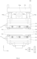
- the structure of the primarily sealing unit 110 is described more specifically with reference to FIG. 4 .
- the structure of the primarily sealing unit 110 may apply also to the secondary sealing unit 140, and it is noted that hereinafter, only the structure of the primarily sealing unit 110 is described for convenience of explanation.
- the primarily sealing unit 110 may include a body part 111, and a press part 112 that is coupled to the body part 111 and presses the battery case 12.
- a pair of thickness adjusting stoppers 113 may be provided at both sides, respectively, of the press part 112.
- the thickness adjusting stoppers 113 are components for adjusting a thickness of the sealing area 12a pressed by the press part 112, and may be provided at the both sides, respectively, of the press part 112 and protrude from the body part 111 toward the battery case 12.
- a protrusion height to which each of the thickness adjusting stoppers 113 protrudes from the body part 111 may be variously set, but preferably, the protrusion height of the thickness adjusting stopper 113 may be set to be longer than a protrusion height of the press part 112.
- the protrusion height of the thickness adjusting stopper 113 may be understood as a height from one surface of the body part 111 to one surface of the thickness adjusting stopper 113, which is disposed in a direction opposite to the body part 111 and in contact with the battery case 12.
- the protrusion height of the press part 112 may be understood as a height from the one surface of the body part 111 to one surface of the press part 112, which is disposed in the direction opposite to the body part 111 and in contact with the battery case 12.
- the primarily sealing unit 110 may be disposed at each of the upper side and the lower side of the battery case 12.
- the primarily sealing unit 110 which is disposed at the upper side of the battery case 12, may further include a tilt adjusting part 115 that adjusts a tilt of each of the body part 111 and the press part 112 so that the thickness of the sealing area 12a of the battery case 12 is uniform.
- the primarily sealing unit 110 may further include an elevating part 114, which is connected to an external elevating device (not shown) and ascends and descends, and the tilt adjusting part 115 which is provided between the elevating part 114 and the body part 111 and adjusts the tilt of each of the body part 111 and the press part 112.
- the tilt adjusting part 115 may include a connecting part 115a, which connects the elevating part 114 and the body part 111 to each other, and a pair of deformation parts 115b, each of which has both ends connected to the elevating part 114 and the body part 111, respectively, and is deformed to be contracted.
- the connecting part 115a may be provided to be rotatable.
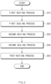
- the present invention provides a battery case 12 sealing method including a first heating process of heating a battery case 12 in which an electrode assembly 11 is accommodated (S10), a first sealing process of pressing and sealing the battery case 12 after the first heating process (S10) (S20), and a second heating process of heating the battery case 12 after the first sealing process (S20) (S30).
- each of the processes may be carried out simultaneously with transfer of the battery case 12.
- the first heating process (S10) may be performed by heating the battery case 12 by using a primarily heating unit 120, which is disposed in front of a primarily sealing unit 110, before the first sealing process (S20). Accordingly, there is an advantage that the battery case 12 may secure a heat amount necessary for the sealing in advance through the first heating process (S10) before the sealing process is performed.
- specific contents of the primarily heating unit 120 may be cited from the foregoing contents.
- the battery case 12 may be heated in a non-contact manner in the first heating process (S10).
- the first heating process (S10) may be performed by heating the battery case 12 in a non-contact manner using high frequency, infrared, ultraviolet, or the like.
- the first sealing process (S20) of sealing the battery case 12 may be performed after the first heating process (S10).
- the first sealing process (S20) is a process of pressing and sealing the battery case 12 after the first heating process (S10), and may be performed in various methods.
- the first sealing process (S20) may be performed by the foregoing primarily sealing unit 110, and specific contents of the primarily sealing unit 110 may be cited from the foregoing contents.
- At least one of a first sealing area 12aa, a second sealing area 12ab, or a third sealing area 12ac may be pressed and sealed in the first sealing process (S20).
- the sealing may be performed limitedly on the first sealing area 12aa, which is disposed to correspond to the electrode lead 13, in the first sealing process (S20).
- the sealing may be performed limitedly on the first sealing area 12aa in the first sealing process (S20), considering that a seal stepped portion may occur when the sealing is performed on the same area multiple times, and since losses of a heat amount necessary for the sealing occur in the electrode lead 13 having a lower rate of temperature rise than the battery case 12, the sealing quality is reduced at a position corresponding to the electrode lead 13.
- the second heating process (S30) of heating the battery case 12 may be performed after the first sealing process (S20).
- the second heating process (S30) is a process of heating the battery case 12 after the first sealing process (S20), and may be performed in various methods.
- the second heating process (S30) may be performed by heating the battery case 12 by using a primarily heating unit 120, which is disposed in rear of the primarily sealing unit 110, after first sealing process (S20).
- a primarily heating unit 120 which is disposed in rear of the primarily sealing unit 110, after first sealing process (S20).
- specific contents of the primarily heating unit 120 may be cited from the foregoing contents.
- the second heating process (S30) may enable an inner resin layer of a sealing area 12a to be sufficiently melted after the sealing is performed, and minimize generation of bubbles according to rapid changes in temperature.
- the inner resin layer of the sealing area 12a may be sufficiently melted through the second heating process (S30) before the sealing is performed through the second sealing process (S40).
- the second heating process (S30) may also help to improve the sealing quality.
- the battery case 12 may be heated in the transfer direction of the battery case 12. Accordingly, the thermal losses that may occur during the transfer of the battery case 12 may be minimized in the second heating process (S30).
- the battery case 12 may be heated in a non-contact manner in the second heating process (S30).
- the second heating process (S30) may be performed by heating the battery case 12 in a non-contact manner using high frequency, infrared, ultraviolet, or the like.
- the battery case 12 sealing method according to the present invention may further include the second sealing process (S40) of sealing the battery case 12 after the first sealing process (S20) and the second heating process (S30).
- the second sealing process (S40) is a process of pressing and sealing the battery case 12 after the first sealing process (S20) and the second heating process (S30), and may be performed in various methods.
- first sealing area 12aa, the second sealing area 12ab, or the third sealing area 12ac may be sealed in the second sealing process (S40).
- a pressing area on which the battery case 12 is pressed in the second sealing process (S40) may be larger than a pressing area on which the battery case 12 is pressed in the first sealing process (S20) described above.
- an area to be sealed in the second sealing process (S40) may be larger than an area to be sealed in the first sealing process (S20), considering that an area that is not sealed in the first sealing process (S20) described above needs to be sealed to form a sealing structure of the battery case 12, and even the area sealed in the first sealing process (S20) described above may be additionally sealed in order to supplement the sealing quality.
- the first sealing area 12aa when only the first sealing area 12aa is pressed and sealed in the first sealing process (S20), at least one of the second sealing area 12ab or the third sealing area 12ac may be sealed together with the first sealing area 12aa in the second sealing process (S40). That is, when only the first sealing area 12aa is sealed in the first sealing process (S20), the first sealing area 12aa and the second sealing area 12ab may be sealed in the second sealing process (S40).
- the battery case sealing method according to the present invention may further include a post-heating process (S50) of heating the battery case 12 after the second sealing process (S40).
- the post-heating process (S50) is a process of heating the battery case 12 after the second sealing process (S40), and may be performed in various methods.
- the post-heating process (S50) may be performed by heating the battery case 12 by using a secondary heating unit 150, which is disposed in rear of the secondary sealing unit 140, after the second sealing process (S40). Accordingly, in the post-heating process (S50), the inner resin layer of the sealing area 12a may be sufficiently melted and generation of bubbles according to rapid changes in temperature may be minimized.
- specific contents of the secondary heating unit 150 may be cited from the foregoing contents.
- the battery case 12 may be heated in the transfer direction of the battery case 12. Accordingly, the thermal losses that may occur during the transfer of the battery case 12 may be minimized in the post-heating process (S50).
- the battery case 12 may be heated in a non-contact manner in the post-heating process (S50).
- the post-heating process (S50) may be performed by heating the battery case 12 in a non-contact manner using high frequency, infrared, ultraviolet, or the like.
Landscapes
- Engineering & Computer Science (AREA)
- Mechanical Engineering (AREA)
- Chemical & Material Sciences (AREA)
- General Chemical & Material Sciences (AREA)
- Electrochemistry (AREA)
- Chemical Kinetics & Catalysis (AREA)
- Physics & Mathematics (AREA)
- Thermal Sciences (AREA)
- Manufacturing & Machinery (AREA)
- Toxicology (AREA)
- Electromagnetism (AREA)
- Health & Medical Sciences (AREA)
- Sealing Battery Cases Or Jackets (AREA)
Abstract
Description
- The present application claims the benefit of the priority of
Korean Patent Application Nos. 10-2021-0183210, filed on December 20, 2021 10-2022-0179477, filed on December 20, 2022 - The present invention relates to a battery case sealing device and a battery case sealing method using the same, and more particularly, to a battery case sealing device, which performs sealing of a pouch type battery case, and a battery case sealing method using the battery case sealing device.
- Batteries (cells) that generate electrical energy through a physical reaction or a chemical reaction of a substance to supply the generated power source to the outside are used when alternating current power source to be supplied to the building is not obtained, or direct current power source is required according to the living environments surrounded by various electrical and electronic devices.
- Among such batteries, primary batteries and secondary batteries, which are chemical batteries using the chemical reaction, are being generally used. The primary batteries are consumable batteries which are collectively referred to as dry batteries. The secondary batteries are rechargeable batteries that are manufactured using a material in which a redox process between a current and a substance is repeatable several times. When a reduction reaction is performed on the material by the current, a power supply is charged, and when an oxidation reaction is performed on the material, the power supply is discharged. Such a charging-discharging is repeatedly performed to generate electricity.
- In recent market, attention has been paid to a pouch type secondary battery having a small volume and a high degree of freedom in design. Specifically, a pouch type secondary battery is a secondary battery in which an electrode assembly is accommodated in a pouch type battery case. Here, the battery case generally has a multi-film structure in which an inner resin layer, a metal layer, and an outer resin layer are sequentially stacked from the inside toward the outside.
- Such a battery case has a sealing structure in which the inner resin layer is thermally fused and sealed at at least a portion of an outer circumference so that the electrode assembly therein is not exposed to external moisture and air.
- As the battery case has an increased thickness for a change in electrode lead thickness and improvement in secondary battery energy density for quick charging of a secondary battery, heat amount and pressure necessary for the sealing of the battery case are required to increase.
- However, in a sealing device having one press according to the related art, when a heating temperature of the press is increased, there are problems that a surface of the battery case is melted or wrinkles are caused by heat, and when pressure at which the press presses the battery case is increased, there is a problem that a portion of the inner resin layer flows to the inside or outside of the battery case.
- In addition, when the heat amount and pressure conditions of the sealing device are decreased, it is apparent that sealing quality is reduced and, in particular, there are problems that thermal losses occur in an electrode lead having a low rate of temperature rise and the sealing quality of the battery case is markedly reduced at a position corresponding to the electrode lead.
- Accordingly, in the sealing device according to the related art, it is very difficult to select the heat amount and pressure conditions for ensuring the sealing quality of the battery case having a large thickness.
- The present invention has been devised to solve the problems as above, and one aspect of the present invention is to provide a battery case sealing device, which is capable of securing sealing quality even when sealing is performed on a battery case having a large thickness, and a battery case sealing method using the battery case sealing device.
- The present invention provides a battery case sealing device including: a primarily sealing unit that presses and seals a battery case in which an electrode assembly is accommodated; a pair of primarily heating units that are disposed in front and rear, respectively, of the primarily sealing unit and heat the battery case; and a transfer part that transfers the battery case.
- The primarily heating units may extend in a transfer direction of the battery case.
- The primarily heating units may heat the battery case in a non-contact manner.
- The battery case may have at least one end from which an electrode lead electrically connected to the electrode assembly protrudes, and the primarily sealing unit may press and seal an area that corresponds to the electrode lead in the battery case.
- Meanwhile, the battery case sealing device according to the present invention may further include a secondary sealing unit that is disposed behind the primarily sealing unit and the primarily heating units and presses and seals the battery case.
- In addition, the battery case sealing device according to the present invention may further include a secondary heating unit that is disposed behind the secondary sealing unit and heats the battery case.
- Moreover, the battery case sealing device according to the present invention may further include a transfer part that transfers the battery case, and the secondary heating unit may extend in the transfer direction of the battery case.
- The secondary heating unit may heat the battery case in a non-contact manner.
- A pressing area on which the secondary sealing unit presses the battery case may be larger than a pressing area on which the primarily sealing unit presses the battery case.
- Meanwhile, the present invention provides a battery case sealing method including: a first heating process of heating a battery case in which an electrode assembly is accommodated; a first sealing process of pressing and sealing the battery case after the first heating process; and a second heating process of heating the battery case after the first sealing process.
- In at least one of the first heating process or the second heating process, the battery case may be heated in a transfer direction of the battery case.
- In at least one of the first heating process or the second heating process, the battery case may be heated in a non-contact manner.
- In the first sealing process, the sealing may be performed at a position corresponding to an electrode lead protruding from at least one end of the electrode assembly.
- Meanwhile, the battery case sealing method according to the present invention may further include a second sealing process of pressing and sealing the battery case after the first sealing process and the second heating process.
- In addition, the battery case sealing method according to the present invention may further include a post-heating process of heating the battery case after the second sealing process.
- According to the preferred embodiments of the present invention, the pair of primarily heating units may be provided in front and rear, respectively, of the primarily sealing unit and thus, there are the advantages that the sufficient heat amount necessary for the battery case sealing may be secured, the rapid changes in temperature of the battery case may be prevented, and the thermal losses during the transfer of the battery case may be prevented to improve the damage to the battery case outer appearance and the sealing quality of the battery case.
- In addition, the secondary sealing unit and the primarily sealing unit may be included to press and seal the sealing area of the battery case multiple times and thus, there is the advantage that the sealing quality may be secured even when the thickness of the battery case increases.
- Moreover, the primarily sealing unit, the secondary sealing unit, the primarily heating unit, and the secondary heating unit may be used to variously select the heat amount and pressure conditions for the sealing of the battery case and thus, there is the advantage that it is possible to quickly and easily correspond to the sealing of the battery case having the large thickness as well.
-
-
FIG. 1 is a front view of a secondary battery. -
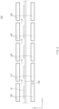
FIGS. 2a to 2d are schematic views sequentially illustrating states in which the secondary battery inFIG. 1 is manufactured. -
FIG. 3 is a schematic conceptual view illustrating a configuration of a battery case sealing device according to Embodiment 1 of the present invention. -
FIG. 4 is a side view more specifically illustrating a configuration of a primarily sealing unit in the battery case sealing device inFIG. 2 . -
FIG. 5 is a flowchart sequentially illustrating a battery case sealing method according to Embodiment 2 of the present invention. - Hereinafter, preferred embodiments of the present invention will be described in detail with reference to the accompanying drawings to enable those skilled in the art to which the present invention pertains to easily carry out the present invention. The present invention may, however, be embodied in different forms and should not be construed as limited by the embodiments set forth herein.
- The parts unrelated to the description, or the detailed descriptions of related well-known art that may unnecessarily obscure subject matters of the present invention, will be ruled out in order to clearly describe the present invention. Like reference numerals refer to like elements throughout the whole specification.
- Moreover, terms or words used in this specification and claims should not be restrictively interpreted as ordinary meanings or dictionary-based meanings, but should be interpreted as meanings and concepts conforming to the scope of the present invention on the basis of the principle that an inventor can properly define the concept of a term to describe and explain his or her invention in the best ways.
- The present invention provides a battery
case sealing device 100 including a primarilysealing unit 110, which presses and seals abattery case 12 in which anelectrode assembly 11 is accommodated, a pair of primarilyheating units 120, which are disposed in front and rear, respectively, of the primarilysealing unit 110 and heat thebattery case 12, and atransfer part 130 that transfers thebattery case 12. - First, the
battery case 12, which is sealed by the batterycase sealing device 100 and constitutes asecondary battery 10 together with theelectrode assembly 11, is described before a configuration of the batterycase sealing device 100 is described. - The
battery case 12 is a component in which theelectrode assembly 11 is accommodated, as illustrated inFIG. 1 , and may have various configurations. Here, theelectrode assembly 11 is a component that is accommodated in thebattery case 12, and it is noted that theelectrode assembly 11 is indicated by dotted lines. - Here, the
electrode assembly 11 is a component, in which an electrode active material is applied onto an electrode collector to configure each of a positive electrode and a negative electrode and a separator is interposed between the positive electrode and the negative electrode, and may have a wound type structure, a stacked type structure, a stack and folding type structure, or the like. Thiselectrode assembly 11 may be accommodated together with an electrolyte in thebattery case 12. - Specifically, the
battery case 12 may be provided with an accommodation part 12', in which theelectrode assembly 11 is accommodated, and have at least one end from which an electrode lead 13 electrically connected to theelectrode assembly 11 protrudes. Here, the accommodation part 12' may be understood as an area that is concavely formed in at least one area of thebattery case 12 so that theelectrode assembly 11 is accommodatable therein. - More specifically, in a state in which the
battery case 12 in which theelectrode assembly 11 is accommodated is unfolded before folding as illustrated inFIG. 2a , thebattery case 12 may be folded in half in a longitudinal direction (y direction inFIG. 2b ) of thebattery case 12 as illustrated inFIG. 2b , thereby manufacturing thebattery case 12. - Such a
battery case 12 may have a sealing structure in order to prevent theelectrode assembly 11, which is accommodated in the accommodation part 12', from being damaged by exposure to external moisture, air, and the like. - Specifically, the
battery case 12 may include asealing area 12a formed by attaching some areas of an outer circumference of thebattery case 12 to each other. Here, when thebattery case 12 is folded or at least twobattery cases 12 are provided to overlap each other and form areas in which thebattery cases 12 are in contact with each other, the outer circumference is heated and/or pressed to attach the areas to each other in an area, and this area may be understood as the sealingarea 12a. - More specifically, the sealing
area 12a may include a first sealing area 12aa, which corresponds to theelectrode lead 13, of the sealingarea 12a formed in the longitudinal direction (y direction inFIG. 1 ) of thebattery case 12, a second sealing area 12ab, which is a remaining area except for the first sealing area 12aa, of the sealingarea 12a formed in the longitudinal direction (y direction inFIG. 1 ) of thebattery case 12, and a third sealing area 12ac which is formed in a width direction (x direction inFIG. 1 ) of thebattery case 12. - Here, the first sealing area 12aa is an area in which the
electrode lead 13 is in contact with thebattery case 12, and may be understood as an area in which sealing between theelectrode lead 13 and thebattery case 12 is performed. - The sealing
area 12a may be formed by performing sealing on the first sealing area 12aa and the second sealing area 12ab as illustrated inFIG. 2c , and then performing sealing on the third sealing area 12ac as illustrated inFIG. 2d . Here, the electrolyte may be introduced into the accommodation part 12' after the sealing is performed on the first sealing area 12aa and the second sealing area 12ab and before the sealing is performed on the third sealing area 12ac. - Meanwhile, the
battery case 12 may be transferred by thetransfer part 130. Specifically, thebattery case 12 may be transferred with theelectrode assembly 11 accommodated therein by thetransfer part 130. Thetransfer part 130 may be constituted by a conveyor belt, a plurality of rollers, or the like. Here, as illustrated inFIG. 3 , thebattery case 12 may be transferred so as to pass the primarily sealingunit 110, the primarily heatingunits 120, asecondary sealing unit 140, and asecondary heating unit 150, which are be described below. - Here, the primarily sealing
unit 110 is a component, which presses and seals thebattery case 12, and may have various configurations. The primarily sealingunit 110 may press and seal an area that corresponds to the electrode lead in the battery case. - Specifically, the primarily sealing
unit 110 may be disposed at at least one of an upper side or a lower side of thebattery case 12 transferred by thetransfer part 130, and press at least a portion of the outer circumference of thebattery case 12, thereby sealing the sealingarea 12a. To this end, the primarily sealingunit 110 may be provided to be vertically movable toward thebattery case 12. Here, the primarily sealingunit 110 may also perform the sealing of the sealingarea 12a by pressing and heating the at least a portion of the outer circumference of thebattery case 12 at the same time. - In more detail, the primarily sealing
unit 110 may press and seal at least one of the first sealing area 12aa, the second sealing area 12ab, or the third sealing area 12ac. That is, when each of the sealing areas is formed to be stepped, the primarily sealingunit 110 may include a shape that is stepped so as to correspond to the shape of each of the sealing areas. - Here, when the
secondary sealing unit 140 to be described later is additionally provided in the present invention, the primarily sealingunit 110 may perform the sealing limitedly on the first sealing area 12aa that is disposed to correspond to theelectrode lead 13 in thebattery case 12. - That is, the primarily sealing
unit 110 may perform the sealing limitedly on the first sealing area 12aa, considering that a seal stepped portion may occur when the sealing is performed on the same area multiple times, and since losses of a heat amount necessary for the sealing occur in theelectrode lead 13 having a lower rate of temperature rise than thebattery case 12, the sealing quality is reduced at a position corresponding to theelectrode lead 13. - Meanwhile, the pair of primarily heating
units 120 may be provided in front and rear, respectively, of the primarily sealingunit 110. Hereinafter, for convenience of explanation, a direction directed to a direction in which thebattery case 12 is transferred on thetransfer part 130 is referred to as a rear side, and a direction opposite to the rear side is referred to a front side. - Specifically, the primarily heating
units 120 are components, which are disposed in front and rear, respectively, of the primarily sealingunit 110 and heat thebattery case 12 as illustrated inFIG. 2 , and may have various configurations. - For example, each of the primarily heating
units 120 may extend in a transfer direction of thebattery case 12 in order to minimize the thermal losses of thebattery case 12, which may be caused by thebattery case 12 transfer. - Specifically, the primarily heating
unit 120 may extend in the transfer direction of thebattery case 12 so as to supply heat to thebattery case 12 continuously. To this end, the primarily heatingunit 120 may include a plurality of heating blocks (not shown) that are arranged in the transfer direction of thebattery case 12. Accordingly, the primarily heatingunit 120 may minimize the thermal losses that may occur in thebattery case 12 during the transfer of thebattery case 12. - In addition, the primarily heating
unit 120 may heat thebattery case 12 in a non-contact manner. - Specifically, the primarily heating
unit 120 may include a non-contact type heating means such as high-frequency heating means, infrared heating means, or ultraviolet heating means, and may be spaced a predetermined distance from thebattery case 12 and heat thebattery case 12 in the non-contact manner. Accordingly, the primarily heatingunit 120 may heat thebattery case 12 simultaneously with the transfer of thebattery case 12 so as to minimize the thermal losses of thebattery case 12 and perform the process continuously. - The primarily heating
unit 120 may form the high temperature atmosphere in thebattery case 12 continuously before the sealing is performed on thebattery case 12 by the primarily sealingunit 110 and after the sealing is performed on thebattery case 12, thereby securing the sealing quality sufficiently without applying excessive pressure. - Here, the high temperature may be understood as a temperature higher than the room temperature. Here, the room temperature means a range of temperatures, which is called a constant temperature in the relevant field. The room temperature generally refers to a temperature at which humans are comfortable, and may be understood to be typically about 15°C to about 20°C. Accordingly, the temperature higher than the room temperature may be a temperature of 20°C or higher, and more specifically, when a material of the inner resin layer of the sealing
area 12a is a polypropylene resin, the temperature higher than the room temperature may be understood to be 160°C to 190°C. - Specifically, the primarily heating
unit 120 of the pair of primarily heatingunits 120, which is disposed in front of the primarily sealingunit 110, may enable thebattery case 12 to secure the heat amount necessary for the sealing in advance before the sealing is performed on thebattery case 12. This allows the inner resin layer of the sealingarea 12a to be sufficiently melted even when thebattery case 12 having a large thickness is sealed, and thus, may help to improve the sealing quality. In other words, when the sealing process is performed in high-temperature and high-pressure environments after the heating by the primarily sealingunit 110, there is a problem that the inner resin layer that has not been melted is pressed and is not precisely sealed. Such a problem may be prevented by preheating by the primarily heatingunit 120 disposed in front of the primarily sealingunit 110. - Here, the thickness of the
battery case 12 may be understood to be 180 um to 190 um. However, it is noted that the thickness of thebattery case 12 is not limited thereto. - In addition, the primarily heating
unit 120 of the pair of primarily heatingunits 120, which is disposed in rear of the primarily sealingunit 110, may prevent rapid changes in temperature of thebattery case 12 after the sealing is performed on thebattery case 12 and minimize generation of bubbles in the inner resin layer. Specifically, when the temperature of thebattery case 12 changes rapidly after the sealing process, the resin layer is rapidly solidified in a state in which the air present in the resin layer has not been discharged, and thus, the problem that the bubbles are formed in the resin layer may occur. That is, the primarily heatingunit 120 disposed in rear of the primarily sealingunit 110 may maintain the high-temperature environments so that the air in the resin layer is gradually discharged. Accordingly, the generation of bubbles in the inner resin layer may be minimized. - Moreover, when the
secondary sealing unit 140 is additionally provided in the present invention and the sealing is performed multiple times, the primarily heatingunit 120 may allow the inner resin layer of the sealingarea 12a to be melted sufficiently before sealing is performed by thesecondary sealing unit 140. Thus, the primarily heatingunit 120 may also help to improve the sealing quality. - Meanwhile, the
battery case 12 sealing device according to the present invention may further include thesecondary sealing unit 140 that is disposed in rear of the primarily sealingunit 110 and the primarily heatingunits 120 and presses and seals thebattery case 12. - Specifically, the
secondary sealing unit 140 is a component, which presses and seals at least a portion of the outer circumference of thebattery case 12, and may have various configurations. - Specifically, the
secondary sealing unit 140 may be disposed at at least one of the upper side or the lower side of thebattery case 12 transferred by thetransfer part 130, and press and seal the at least a portion of the outer circumference of thebattery case 12. To this end, thesecondary sealing unit 140 may be provided to be vertically movable toward thebattery case 12. Here, thesecondary sealing unit 140 may also perform the sealing on thesealing area 12a by pressing and heating the at least a portion of the outer circumference of thebattery case 12 at the same time. - Meanwhile, the
secondary sealing unit 140 may seal at least one of the first sealing area 12aa, the second sealing area 12ab, or the third sealing area 12ac described above. - Here, a pressing area on which the
secondary sealing unit 140 presses thebattery case 12 may be larger than a pressing area on which the primarily sealingunit 110 presses thebattery case 12. - Specifically, the
secondary sealing unit 140 may press and seal a larger area than the primarily sealingunit 110, considering that an area that is not sealed by the primarily sealingunit 110 needs to be sealed to form a sealing structure of thebattery case 12, and even an area sealed by the primarily sealingunit 110 may be additionally sealed in order to supplement the sealing quality. - For example, when the primarily sealing
unit 110 presses and seals the first sealing area 12aa, thesecondary sealing unit 140 may press and seal at least one of the second sealing area 12ab or the third sealing area 12ac together with the first sealing area 12aa. - Meanwhile, the present invention may further include the
secondary heating unit 150 that is disposed in rear of thesecondary sealing unit 140 and heats thebattery case 12. - Specifically, the
secondary heating unit 150 is a component, which heats thebattery case 12, and may have various configurations. - For example, the
secondary heating unit 150 may extend in the transfer direction of thebattery case 12 in order to minimize the thermal losses of thebattery case 12, which may be caused by thebattery case 12 transfer. - Specifically, the
secondary heating unit 150 may extend in the transfer direction of thebattery case 12 so as to supply heat to thebattery case 12 continuously. To this end, thesecondary heating unit 150 may include a plurality of heating blocks (not shown) that are arranged in the transfer direction of thebattery case 12. Accordingly, thesecondary heating unit 150 may minimize the thermal losses that may occur in thebattery case 12 during the transfer of thebattery case 12. - In addition, the
secondary heating unit 150 may heat thebattery case 12 in a non-contact manner. - Specifically, the
secondary heating unit 150 may be spaced a predetermined distance from thebattery case 12 and heat thebattery case 12 in the non-contact manner through a non-contact type heating means such as high-frequency heating means, infrared heating means, or ultraviolet heating means. Accordingly, thesecondary heating unit 150 may heat thebattery case 12 simultaneously with the transfer of thebattery case 12 and thus, may minimize the thermal losses of thebattery case 12 and may perform the process continuously. - The
secondary heating unit 150 may prevent rapid changes in temperature of thebattery case 12 after the sealing is performed on thebattery case 12, and minimize generation of bubbles in the inner resin layer. - Meanwhile, the primarily sealing
unit 110 may have various structures. - Hereinafter, the structure of the primarily sealing
unit 110 is described more specifically with reference toFIG. 4 . The structure of the primarily sealingunit 110 may apply also to thesecondary sealing unit 140, and it is noted that hereinafter, only the structure of the primarily sealingunit 110 is described for convenience of explanation. - For example, as illustrated in
FIG. 4 , the primarily sealingunit 110 may include abody part 111, and apress part 112 that is coupled to thebody part 111 and presses thebattery case 12. - Here, the
body part 111 may have a structure in which multiples blocks are stacked and bolt-coupled to each other. Here, at least one of the blocks may be connected to an external electrical device and generate the temperature higher than the room temperature. Here, the meaning of the room temperature may be cited from the foregoing contents. - The
press part 112 is a component, which presses thebattery case 12, and may have various configurations. - For example, the
press part 112 may protrude from one surface of thebody part 111 toward thebattery case 12 and perform the pressing of the sealingarea 12a described above. Here, the sealingarea 12a may include at least one of the first sealing area 12aa, the second sealing area 12ab, or the third sealing area 12ac. Thispress part 112 may have various shapes. Here, thepress part 112 may be changed to correspond to the shape of the sealingarea 12a. - Meanwhile, a pair of
thickness adjusting stoppers 113 may be provided at both sides, respectively, of thepress part 112. - Specifically, the
thickness adjusting stoppers 113 are components for adjusting a thickness of the sealingarea 12a pressed by thepress part 112, and may be provided at the both sides, respectively, of thepress part 112 and protrude from thebody part 111 toward thebattery case 12. - Here, a protrusion height to which each of the
thickness adjusting stoppers 113 protrudes from thebody part 111 may be variously set, but preferably, the protrusion height of thethickness adjusting stopper 113 may be set to be longer than a protrusion height of thepress part 112. Here, the protrusion height of thethickness adjusting stopper 113 may be understood as a height from one surface of thebody part 111 to one surface of thethickness adjusting stopper 113, which is disposed in a direction opposite to thebody part 111 and in contact with thebattery case 12. The protrusion height of thepress part 112 may be understood as a height from the one surface of thebody part 111 to one surface of thepress part 112, which is disposed in the direction opposite to thebody part 111 and in contact with thebattery case 12. - Meanwhile, as illustrated in
FIG. 4 , the primarily sealingunit 110 may be disposed at each of the upper side and the lower side of thebattery case 12. Here, the primarily sealingunit 110, which is disposed at the upper side of thebattery case 12, may further include atilt adjusting part 115 that adjusts a tilt of each of thebody part 111 and thepress part 112 so that the thickness of the sealingarea 12a of thebattery case 12 is uniform. - Specifically, the primarily sealing
unit 110 may further include an elevatingpart 114, which is connected to an external elevating device (not shown) and ascends and descends, and thetilt adjusting part 115 which is provided between the elevatingpart 114 and thebody part 111 and adjusts the tilt of each of thebody part 111 and thepress part 112. - More specifically, the
tilt adjusting part 115 may include a connectingpart 115a, which connects the elevatingpart 114 and thebody part 111 to each other, and a pair ofdeformation parts 115b, each of which has both ends connected to the elevatingpart 114 and thebody part 111, respectively, and is deformed to be contracted. - That is, when one of the pair of
deformation parts 115b contracts, the other may stretch to adjust the tilt of each of thebody part 111 and thepress part 112. Here, the connectingpart 115a may be provided to be rotatable. - Meanwhile, the
tilt adjusting part 115 may further include a pair oftilt stoppers 115c that restrict a tilt degree of each of thebody part 111 and thepress part 112. Here, thetilt stoppers 115c may protrude from the elevatingpart 114 and thebody part 111, respectively, so as to face each other, and may be provided so as to be spaced apart from each other. Accordingly, when each of thebody part 111 and thepress part 112 is inclined at a preset angle or greater, thetilt stoppers 115c may mechanically restrict the tilt of each of thebody part 111 and thepress part 112. - Meanwhile, as illustrated in
FIG. 5 , the present invention provides abattery case 12 sealing method including a first heating process of heating abattery case 12 in which anelectrode assembly 11 is accommodated (S10), a first sealing process of pressing and sealing thebattery case 12 after the first heating process (S10) (S20), and a second heating process of heating thebattery case 12 after the first sealing process (S20) (S30). Here, each of the processes may be carried out simultaneously with transfer of thebattery case 12. - Here, the first heating process (S10) is a process of heating the
battery case 12 in which theelectrode assembly 11 is accommodated, and may be performed through various methods. - Specifically, the first heating process (S10) may be performed by heating the
battery case 12 by using a primarily heatingunit 120, which is disposed in front of a primarily sealingunit 110, before the first sealing process (S20). Accordingly, there is an advantage that thebattery case 12 may secure a heat amount necessary for the sealing in advance through the first heating process (S10) before the sealing process is performed. Here, specific contents of the primarily heatingunit 120 may be cited from the foregoing contents. - In this first heating process (S10), the
battery case 12 may be heated in a transfer direction of thebattery case 12. Accordingly, the first heating process (S10) may minimize thermal losses that may occur during the transfer of thebattery case 12. - In addition, the
battery case 12 may be heated in a non-contact manner in the first heating process (S10). Specifically, the first heating process (S10) may be performed by heating thebattery case 12 in a non-contact manner using high frequency, infrared, ultraviolet, or the like. - Meanwhile, the first sealing process (S20) of sealing the
battery case 12 may be performed after the first heating process (S10). - Specifically, the first sealing process (S20) is a process of pressing and sealing the
battery case 12 after the first heating process (S10), and may be performed in various methods. Here, the first sealing process (S20) may be performed by the foregoing primarily sealingunit 110, and specific contents of the primarily sealingunit 110 may be cited from the foregoing contents. - Here, at least one of a first sealing area 12aa, a second sealing area 12ab, or a third sealing area 12ac may be pressed and sealed in the first sealing process (S20).
- Here, when a second sealing process (S40) to be described later is additionally provided in the present invention, the sealing may be performed limitedly on the first sealing area 12aa, which is disposed to correspond to the
electrode lead 13, in the first sealing process (S20). - That is, the sealing may be performed limitedly on the first sealing area 12aa in the first sealing process (S20), considering that a seal stepped portion may occur when the sealing is performed on the same area multiple times, and since losses of a heat amount necessary for the sealing occur in the
electrode lead 13 having a lower rate of temperature rise than thebattery case 12, the sealing quality is reduced at a position corresponding to theelectrode lead 13. - Meanwhile, the second heating process (S30) of heating the
battery case 12 may be performed after the first sealing process (S20). - Specifically, the second heating process (S30) is a process of heating the
battery case 12 after the first sealing process (S20), and may be performed in various methods. - Specifically, the second heating process (S30) may be performed by heating the
battery case 12 by using a primarily heatingunit 120, which is disposed in rear of the primarily sealingunit 110, after first sealing process (S20). Here, specific contents of the primarily heatingunit 120 may be cited from the foregoing contents. - Accordingly, the second heating process (S30) may enable an inner resin layer of a
sealing area 12a to be sufficiently melted after the sealing is performed, and minimize generation of bubbles according to rapid changes in temperature. - In addition, when the second sealing process (S40) to be described later is additionally provided in the present invention and the sealing is performed multiple times, the inner resin layer of the sealing
area 12a may be sufficiently melted through the second heating process (S30) before the sealing is performed through the second sealing process (S40). Thus, the second heating process (S30) may also help to improve the sealing quality. - In this second heating process (S30), the
battery case 12 may be heated in the transfer direction of thebattery case 12. Accordingly, the thermal losses that may occur during the transfer of thebattery case 12 may be minimized in the second heating process (S30). - In addition, the
battery case 12 may be heated in a non-contact manner in the second heating process (S30). Specifically, the second heating process (S30) may be performed by heating thebattery case 12 in a non-contact manner using high frequency, infrared, ultraviolet, or the like. - Meanwhile, the
battery case 12 sealing method according to the present invention may further include the second sealing process (S40) of sealing thebattery case 12 after the first sealing process (S20) and the second heating process (S30). - Specifically, the second sealing process (S40) is a process of pressing and sealing the
battery case 12 after the first sealing process (S20) and the second heating process (S30), and may be performed in various methods. - Here, the second sealing process (S40) may supplement the sealing of the
battery case 12 by pressing and sealing an area, which is not pressed in the first sealing process (S20) described above, by using the foregoingsecondary sealing unit 140 described above, or by additionally pressing an area that is pressed and sealed in the first sealing process (S20). Here, specific contents of thesecondary sealing unit 140 may be cited from the foregoing contents. - Specifically, at least one of the first sealing area 12aa, the second sealing area 12ab, or the third sealing area 12ac may be sealed in the second sealing process (S40).
- Here, a pressing area on which the
battery case 12 is pressed in the second sealing process (S40) may be larger than a pressing area on which thebattery case 12 is pressed in the first sealing process (S20) described above. - Specifically, an area to be sealed in the second sealing process (S40) may be larger than an area to be sealed in the first sealing process (S20), considering that an area that is not sealed in the first sealing process (S20) described above needs to be sealed to form a sealing structure of the
battery case 12, and even the area sealed in the first sealing process (S20) described above may be additionally sealed in order to supplement the sealing quality. - For example, when only the first sealing area 12aa is pressed and sealed in the first sealing process (S20), at least one of the second sealing area 12ab or the third sealing area 12ac may be sealed together with the first sealing area 12aa in the second sealing process (S40). That is, when only the first sealing area 12aa is sealed in the first sealing process (S20), the first sealing area 12aa and the second sealing area 12ab may be sealed in the second sealing process (S40).
- Meanwhile, the battery case sealing method according to the present invention may further include a post-heating process (S50) of heating the
battery case 12 after the second sealing process (S40). - Specifically, the post-heating process (S50) is a process of heating the
battery case 12 after the second sealing process (S40), and may be performed in various methods. - Specifically, the post-heating process (S50) may be performed by heating the
battery case 12 by using asecondary heating unit 150, which is disposed in rear of thesecondary sealing unit 140, after the second sealing process (S40). Accordingly, in the post-heating process (S50), the inner resin layer of the sealingarea 12a may be sufficiently melted and generation of bubbles according to rapid changes in temperature may be minimized. Here, specific contents of thesecondary heating unit 150 may be cited from the foregoing contents. - In this post-heating process (S50), the
battery case 12 may be heated in the transfer direction of thebattery case 12. Accordingly, the thermal losses that may occur during the transfer of thebattery case 12 may be minimized in the post-heating process (S50). - In addition, the
battery case 12 may be heated in a non-contact manner in the post-heating process (S50). Specifically, the post-heating process (S50) may be performed by heating thebattery case 12 in a non-contact manner using high frequency, infrared, ultraviolet, or the like. - Although the present invention has been described with reference to the limited embodiments and drawings, the present invention is not limited thereto and may be variously implemented by those of ordinary skill in the art to which the present invention pertains, within the technical idea of the present invention and an equivalent of the appended claims.
-
- 10: Secondary battery
- 11: Electrode assembly
- 12: Battery case
- 12' Accommodation part
- 12a: Sealing area
- 12aa: First sealing area
- 12ab: Second sealing area
- 12ac: Third sealing area
- 13: Electrode lead
- 100: Battery case sealing device
- 110: Primarily sealing unit
- 111: Body part
- 112: Press part
- 113: Thickness adjusting stopper
- 114: Elevating part
- 115: Tilt adjusting part
- 115a: Connecting part
- 115b: Deformation part
- 115c: Tilt stopper
- 120: Primarily heating unit
- 130: transfer part
- 140: Secondary sealing unit
- 150: Secondary heating unit
- S10: First heating process
- S20: First heating process
- S30: Second heating process
- S40: Second sealing process
- S50: Post-heating process
Claims (15)
- A battery case sealing device comprising:a primarily sealing unit configured to press and seal a battery case in which an electrode assembly is accommodated;a pair of primarily heating units disposed in front and rear, respectively, of the primarily sealing unit and configured to heat the battery case; anda transfer part configured to transfer the battery case along a transfer line.
- The battery case sealing device of claim 1, wherein the primarily heating units are provided in the transfer line in a transfer direction of the battery case,
wherein one of the pair of primarily heating units is disposed in front of the primarily sealing unit, and the other of the pair of primarily heating units is disposed behind the primarily sealing unit in the transfer direction of the battery case. - The battery case sealing device of claim 1, wherein the primarily heating units heat the battery case in a non-contact manner.
- The battery case sealing device of claim 1, wherein the battery case has at least one end from which an electrode lead electrically connected to the electrode assembly protrudes,
wherein the primarily sealing unit presses and seals an area that corresponds to the electrode lead in the battery case. - The battery case sealing device of claim 1, further comprising a secondary sealing unit disposed behind the primarily sealing unit and the primarily heating units and configured to press and seal the battery case.
- The battery case sealing device of claim 5, further comprising a secondary heating unit disposed behind the secondary sealing unit and configured to heat the battery case.
- The battery case sealing device of claim 6, further comprising a transfer part configured to transfer the battery case,
wherein the secondary heating unit extends in the transfer direction of the battery case. - The battery case sealing device of claim 6, wherein the secondary heating unit heats the battery case in a non-contact manner.
- The battery case sealing device of claim 5, wherein a pressing area, on which the secondary sealing unit presses the battery case, is larger than a pressing area on which the primarily sealing unit presses the battery case.
- A battery case sealing method comprising:a first heating process of heating a battery case in which an electrode assembly is accommodated;a first sealing process of pressing and sealing the battery case after the first heating process; anda second heating process of heating the battery case after the first sealing process.
- The battery case sealing method of claim 10, wherein, in at least one of the first heating process or the second heating process, the battery case is heated in a transfer direction of the battery case.
- The battery case sealing method of claim 10, wherein, in at least one of the first heating process or the second heating process, the battery case is heated in a non-contact manner.
- The battery case sealing method of claim 10, wherein, in the first sealing process, the sealing is performed at a position corresponding to an electrode lead protruding from at least one end of the electrode assembly.
- The battery case sealing method of claim 10, further comprising a second sealing process of pressing and sealing the battery case after the first sealing process and the second heating process.
- The battery case sealing method of claim 14, further comprising a post-heating process of heating the battery case after the second sealing process.
Applications Claiming Priority (2)
| Application Number | Priority Date | Filing Date | Title |
|---|---|---|---|
| KR20210183210 | 2021-12-20 | ||
| PCT/KR2022/020883 WO2023121252A1 (en) | 2021-12-20 | 2022-12-20 | Battery case sealing device and battery case sealing method using same |
Publications (2)
| Publication Number | Publication Date |
|---|---|
| EP4434730A1 true EP4434730A1 (en) | 2024-09-25 |
| EP4434730A4 EP4434730A4 (en) | 2025-04-09 |
Family
ID=86947126
Family Applications (1)
| Application Number | Title | Priority Date | Filing Date |
|---|---|---|---|
| EP22911885.6A Pending EP4434730A4 (en) | 2021-12-20 | 2022-12-20 | BATTERY CASE SEALING DEVICE AND BATTERY CASE SEALING METHOD THEREOF |
Country Status (3)
| Country | Link |
|---|---|
| EP (1) | EP4434730A4 (en) |
| KR (1) | KR20230094176A (en) |
| CN (1) | CN118339011A (en) |
Families Citing this family (2)
| Publication number | Priority date | Publication date | Assignee | Title |
|---|---|---|---|---|
| KR20250148367A (en) | 2024-04-02 | 2025-10-14 | 주식회사 엘지에너지솔루션 | A Pouch Battery Cell Sealing Device That Can Be Easily Aligned In Position And A Pouch Battery Cell Sealing Method Using The Same |
| WO2025211905A1 (en) | 2024-04-02 | 2025-10-09 | 주식회사 엘지에너지솔루션 | Apparatus for sealing pouch battery cell with easy position alignment and method for sealing pouch battery cell using same |
Family Cites Families (4)
| Publication number | Priority date | Publication date | Assignee | Title |
|---|---|---|---|---|
| KR102287763B1 (en) * | 2016-11-03 | 2021-08-10 | 주식회사 엘지에너지솔루션 | Manufacturing system of battery cell |
| KR102828253B1 (en) * | 2018-08-29 | 2025-07-04 | 에스케이온 주식회사 | Non-contact sealing method of pouch type secondary battery |
| WO2021167130A1 (en) * | 2020-02-19 | 2021-08-26 | 엘지전자 주식회사 | Pouch-type secondary battery packaging equipment |
| US12261261B2 (en) * | 2020-05-22 | 2025-03-25 | Lg Electronics Inc. | Pouched-type secondary battery packaging equipment |
-
2022
- 2022-12-20 CN CN202280079664.4A patent/CN118339011A/en active Pending
- 2022-12-20 EP EP22911885.6A patent/EP4434730A4/en active Pending
- 2022-12-20 KR KR1020220179477A patent/KR20230094176A/en active Pending
Also Published As
| Publication number | Publication date |
|---|---|
| KR20230094176A (en) | 2023-06-27 |
| CN118339011A (en) | 2024-07-12 |
| EP4434730A4 (en) | 2025-04-09 |
Similar Documents
| Publication | Publication Date | Title |
|---|---|---|
| EP4434730A1 (en) | Battery case sealing device and battery case sealing method using same | |
| JP6039086B2 (en) | Pouch type secondary battery sealing tool | |
| KR101713042B1 (en) | High Temperature Pressing Device for Battery Cell | |
| US12420489B2 (en) | Sealing apparatus for secondary battery | |
| KR102227668B1 (en) | Laminating method | |
| EP4477389A1 (en) | Folding device and folding method for pouch-type secondary battery sealing portion | |
| JP2018106930A (en) | Battery cell manufacturing method and pressure magazine | |
| KR20180028708A (en) | Electrode coating apparatus | |
| JP7801034B2 (en) | Electrode assembly, electrode assembly manufacturing apparatus, and electrode assembly manufacturing method | |
| JP7754295B2 (en) | Electrode manufacturing method | |
| ES3045784T3 (en) | Device and method for manufacturing secondary battery | |
| US20250357586A1 (en) | Battery Case Sealing Device and Battery Case Sealing Method Using the Same | |
| KR20180118995A (en) | Secondary battery and sealing device for the same and sealing methode for the same | |
| EP4270564A1 (en) | Method and apparatus for manufacturing unit cell | |
| EP4270567B1 (en) | Unit cell preparation method and apparatus | |
| KR102940420B1 (en) | Battery cell bending apparatus and mehtod | |
| KR20230162235A (en) | Electrode Assembly Manufacturing Apparatus for Preventing Folding of Separator and Electrode Assembly Manufactured Using the Same | |
| KR102903643B1 (en) | Apparatus for drying electrode | |
| KR20240065834A (en) | Sealing device for secondary battery | |
| EP4270566A1 (en) | Method and device for manufacturing unit cell | |
| US20250309327A1 (en) | Preheating apparatus and method of manufacturing all-solid-state battery including preheating process using the same | |
| JP7772340B2 (en) | Sealing device and method for pouch-type secondary battery | |
| EP4401207A1 (en) | Sealing method for pouch type secondary battery, manufacturing method for pouch type secondary battery, sealing device for pouch type secondary battery, and pouch type secondary battery manufactured using same | |
| KR20220161179A (en) | Method for fabricating secondary battery of pouch type | |
| KR20260033180A (en) | Apparatus and method for manufactoring pouch-type secondary battery |
Legal Events
| Date | Code | Title | Description |
|---|---|---|---|
| STAA | Information on the status of an ep patent application or granted ep patent |
Free format text: STATUS: THE INTERNATIONAL PUBLICATION HAS BEEN MADE |
|
| PUAI | Public reference made under article 153(3) epc to a published international application that has entered the european phase |
Free format text: ORIGINAL CODE: 0009012 |
|
| STAA | Information on the status of an ep patent application or granted ep patent |
Free format text: STATUS: REQUEST FOR EXAMINATION WAS MADE |
|
| 17P | Request for examination filed |
Effective date: 20240618 |
|
| AK | Designated contracting states |
Kind code of ref document: A1 Designated state(s): AL AT BE BG CH CY CZ DE DK EE ES FI FR GB GR HR HU IE IS IT LI LT LU LV MC ME MK MT NL NO PL PT RO RS SE SI SK SM TR |
|
| DAV | Request for validation of the european patent (deleted) | ||
| DAX | Request for extension of the european patent (deleted) | ||
| A4 | Supplementary search report drawn up and despatched |
Effective date: 20250310 |
|
| RIC1 | Information provided on ipc code assigned before grant |
Ipc: H01M 10/04 20060101ALI20250304BHEP Ipc: B29L 31/00 20060101ALI20250304BHEP Ipc: H01M 50/178 20210101ALI20250304BHEP Ipc: H01M 50/105 20210101ALI20250304BHEP Ipc: B29C 65/00 20060101AFI20250304BHEP |
|
| STAA | Information on the status of an ep patent application or granted ep patent |
Free format text: STATUS: EXAMINATION IS IN PROGRESS |
|
| 17Q | First examination report despatched |
Effective date: 20250806 |
|
| GRAP | Despatch of communication of intention to grant a patent |
Free format text: ORIGINAL CODE: EPIDOSNIGR1 |
|
| STAA | Information on the status of an ep patent application or granted ep patent |
Free format text: STATUS: GRANT OF PATENT IS INTENDED |
|
| INTG | Intention to grant announced |
Effective date: 20260304 |