EP4434677A1 - Power tool - Google Patents
Power tool Download PDFInfo
- Publication number
- EP4434677A1 EP4434677A1 EP23182556.3A EP23182556A EP4434677A1 EP 4434677 A1 EP4434677 A1 EP 4434677A1 EP 23182556 A EP23182556 A EP 23182556A EP 4434677 A1 EP4434677 A1 EP 4434677A1
- Authority
- EP
- European Patent Office
- Prior art keywords
- axis
- working head
- output shaft
- equal
- power tool
- Prior art date
- Legal status (The legal status is an assumption and is not a legal conclusion. Google has not performed a legal analysis and makes no representation as to the accuracy of the status listed.)
- Granted
Links
Images



Classifications
-
- B—PERFORMING OPERATIONS; TRANSPORTING
- B25—HAND TOOLS; PORTABLE POWER-DRIVEN TOOLS; MANIPULATORS
- B25B—TOOLS OR BENCH DEVICES NOT OTHERWISE PROVIDED FOR, FOR FASTENING, CONNECTING, DISENGAGING, OR HOLDING
- B25B21/00—Portable power-driven screw or nut setting or loosening tools; Attachments for drilling apparatus serving the same purpose
-
- B—PERFORMING OPERATIONS; TRANSPORTING
- B25—HAND TOOLS; PORTABLE POWER-DRIVEN TOOLS; MANIPULATORS
- B25B—TOOLS OR BENCH DEVICES NOT OTHERWISE PROVIDED FOR, FOR FASTENING, CONNECTING, DISENGAGING, OR HOLDING
- B25B23/00—Details of, or accessories for, spanners, wrenches, screwdrivers
- B25B23/0007—Connections or joints between tool parts
- B25B23/0014—Screwdriver- or wrench-heads provided with cardan joints or the like
-
- B—PERFORMING OPERATIONS; TRANSPORTING
- B25—HAND TOOLS; PORTABLE POWER-DRIVEN TOOLS; MANIPULATORS
- B25B—TOOLS OR BENCH DEVICES NOT OTHERWISE PROVIDED FOR, FOR FASTENING, CONNECTING, DISENGAGING, OR HOLDING
- B25B23/00—Details of, or accessories for, spanners, wrenches, screwdrivers
- B25B23/0007—Connections or joints between tool parts
- B25B23/0028—Angular adjustment means between tool head and handle
-
- B—PERFORMING OPERATIONS; TRANSPORTING
- B25—HAND TOOLS; PORTABLE POWER-DRIVEN TOOLS; MANIPULATORS
- B25F—COMBINATION OR MULTI-PURPOSE TOOLS NOT OTHERWISE PROVIDED FOR; DETAILS OR COMPONENTS OF PORTABLE POWER-DRIVEN TOOLS NOT PARTICULARLY RELATED TO THE OPERATIONS PERFORMED AND NOT OTHERWISE PROVIDED FOR
- B25F5/00—Details or components of portable power-driven tools not particularly related to the operations performed and not otherwise provided for
- B25F5/001—Gearings, speed selectors, clutches or the like specially adapted for rotary tools
-
- B—PERFORMING OPERATIONS; TRANSPORTING
- B25—HAND TOOLS; PORTABLE POWER-DRIVEN TOOLS; MANIPULATORS
- B25F—COMBINATION OR MULTI-PURPOSE TOOLS NOT OTHERWISE PROVIDED FOR; DETAILS OR COMPONENTS OF PORTABLE POWER-DRIVEN TOOLS NOT PARTICULARLY RELATED TO THE OPERATIONS PERFORMED AND NOT OTHERWISE PROVIDED FOR
- B25F5/00—Details or components of portable power-driven tools not particularly related to the operations performed and not otherwise provided for
- B25F5/02—Construction of casings, bodies or handles
Definitions
- the present application relates to a power tool and, in particular, to a hand-held power tool.
- Power tools include hand-held power tools and benchtop power tools. Higher demands are placed on the flexibility of working conditions and the compactness of the hand-held power tools aimed at DIY enthusiasts and home users among the hand-held power tools.
- rotary hand-held power tools such as screwdrivers and drill tools are generally available in either a straight profile or an angular profile to adapt to different usage scenarios. In some cases where straight and angular tools must work together, both tools must be on hand for constant alternation.
- An object of the present application is to provide a power tool.
- a power tool includes a main housing provided with an accommodation space; a drive mechanism at least partially accommodated in the accommodation space and including a motor; a working head including an output shaft, where the output shaft is driven by the drive mechanism to rotate about an output axis; and a connection assembly including an input portion connected to the drive mechanism and an output portion connected to the output shaft, where the connection assembly rotates the working head about a first axis relative to the main housing.
- the power tool includes a first transmission path, the first transmission path is a torque transmission path from the drive mechanism through the connection assembly to the output shaft, and when the working head rotates about the first axis relative to the main housing, components in the first transmission path are allowed to deform or to be displaced along a direction of the first transmission path.
- the working head includes a limit position for making the working head move about the first axis to a limit, where when the working head is located at the limit position, the included angle ⁇ between an axis of the input portion and an axis of the output portion is less than or equal to 85 degrees.
- the working head includes a limit position for making the working head move about the first axis to a limit, where when the working head is located at the limit position, the included angle ⁇ between an axis of the input portion and an axis of the output portion is less than or equal to 70 degrees.
- the working head further includes a first position for making the axis of the input portion parallel to or coincident with the axis of the output portion.
- the limit position includes a first limit position for making the working head move along a first direction about the first axis to a limit, and the first limit position is located on a side of the first position.
- the limit position further includes a second limit position for making the working head move along a second direction opposite to the first direction about the first axis to a limit, and the first limit position and the second limit position are located on two sides of the first position.
- the ratio of the output torque of the output shaft when the working head is located at the limit position to the output torque of the output shaft when the working head is located at the first position is greater than or equal to 0.5 and less than or equal to 1.
- the output torque of the output shaft is greater than or equal to 2.5 N ⁇ m.
- the ratio of the distance L1 between the first axis and a front end of the output shaft to the maximum distance L between a rear end of the main housing and the front end of the output shaft is greater than or equal to 0.1 and less than or equal to 0.4.
- the ratio of the distance L1 between the first axis and a front end of the output shaft to the maximum distance L between a rear end of the main housing and the front end of the output shaft is greater than or equal to 0.1 and less than or equal to 0.3.
- the drive mechanism includes a direct current power supply.
- the direct current power supply includes a battery and has a nominal voltage less than or equal to 7.2 V.
- the ratio of the length L2 of the direct current power supply to the maximum distance L between a rear end of the main housing and a front end of the output shaft is greater than or equal to 0.1 and less than or equal to 0.6.
- connection assembly when the working head rotates about the first axis relative to the main housing, the connection assembly is allowed to deform.
- At least one of the drive mechanism, the input portion, the output portion, and the output shaft is allowed to be displaced along the direction of the first transmission path.
- a power tool includes a main housing provided with an accommodation space; a drive mechanism at least partially accommodated in the accommodation space and including a direct current power supply and a motor; a working head including an output shaft, where the output shaft is driven by the drive mechanism to rotate about an output axis; and a connection assembly connecting the output shaft to the drive mechanism and including at least one connector, where the at least one connector provides at least two orthogonal rotational degrees of freedom to rotate the working head about a first axis relative to the main housing.
- a power tool includes a main housing provided with an accommodation space; a drive mechanism at least partially accommodated in the accommodation space and including a direct current power supply and a motor; a working head including an output shaft, where the output shaft is driven by the drive mechanism to rotate about an output axis; and a connection assembly connecting the output shaft to the drive mechanism and including at least one connector, where the at least one connector provides at least two orthogonal rotational degrees of freedom to rotate the working head about a first axis relative to the main housing.
- the ratio of the distance L1 between the first axis and a front end of the output shaft to the maximum distance L between a rear end of the main housing and the front end of the output shaft is greater than or equal to 0.1 and less than or equal to 0.4.
- the ratio of the distance L1 between the first axis and the front end of the output shaft to the maximum distance L between the rear end of the main housing and the front end of the output shaft is greater than or equal to 0.1 and less than or equal to 0.3.
- the working head includes a limit position for making the working head move about the first axis to a limit, where when the working head is located at the limit position, the included angle ⁇ between an axis of the motor and an axis of the output shaft is less than or equal to 85 degrees.
- the direct current power supply includes a battery and has a nominal voltage less than or equal to 7.2 V, and the maximum output torque of the output shaft is greater than or equal to 2.5 N m.
- connection may refer to “fixedly connected”, “detachably connected”, or integrated, may refer to “mechanically connected” or “electrically connected”, or may refer to “connected directly”, “connected indirectly through an intermediary”, “connected inside two elements”, or “interaction relations between two elements”.
- connection relations between two elements.
- first feature and the second feature may be in direct contact or be in contact via another feature between the two features instead of being in direct contact.
- first feature is described as “on”, “above”, or “over” the second feature
- first feature is right on, above, or over the second feature or the first feature is obliquely on, above, or over the second feature, or the first feature is simply at a higher level than the second feature.
- the first feature When the first feature is described as “under”, “below”, or “underneath” the second feature, the first feature is right under, below, or underneath the second feature or the first feature is obliquely under, below, or underneath the second feature, or the first feature is simply at a lower level than the second feature.
- a power tool 1 includes a working head 10, a main housing 20, and a drive mechanism 30.
- the working head 10 may output power directly or may be connected to another work accessory to output power.
- the power tool 1 may be a corresponding tool, such as a screwdriver, a drill, or a wrench.
- the working head 10 is connected to the main housing 20 and rotates about a first axis 101 relative to the main housing 20 under the action of an external force.
- the working head 10 is connected to the drive mechanism 30 and outputs power under the action of the drive mechanism 30.
- the working head 10 includes an output shaft 11.
- the output shaft 11 is driven by the drive mechanism 30 to rotate about an output axis 102.
- the screwdriver is used as an example, and a mounting groove 111 to which different bits are mounted is further formed at the end of the output shaft 11.
- the mounting groove 111 is a standard hexagonal groove.
- the power tool is the wrench, and a mounting head for mounting a sleeve is formed at or connected to the end of the output shaft 11.
- the power tool is the drill, and a collet assembly for holding a drill bit is connected to the end of the output shaft 11.
- the main housing 20 includes a grip 22 and a connecting portion 21, where the connecting portion 21 is formed at or connected to an end of the grip 22, and the connecting portion 21 is used for connecting the working head 10.
- the main housing 20 extends along a third axis 103 as a whole.
- the connecting portion 21 is located at the upper end of the main housing, that is to say, the working head 10 is connected to the upper end of the main housing 20.
- the connecting portion 21 is formed with a first accommodation space.
- the grip 22 is disposed below the connecting portion.
- the grip 22 is formed with a second accommodation space, and the first accommodation space communicates with the second accommodation space.
- Most of the drive mechanism 30 is disposed in the second accommodation space formed by the grip 22. It is to be understood that the main housing 20 is substantially in the shape of a straight tube.
- the drive mechanism 30 includes a motor 32 and a direct current power supply 33.
- the motor 32 includes a drive shaft rotatable about a drive axis.
- the drive axis coincides with the third axis 103.
- the drive axis and the third axis 103 are parallel to each other but do not coincide.
- a certain included angle exists between the drive axis and the third axis 103.
- the motor 32 is specifically an electric motor, and the electric motor 32 is used below instead of the motor in the subsequent description, but it does not serve as a limitation of the present invention.
- the direct current power supply 33 is specifically a battery or a battery pack.
- the battery or the battery pack mates with a corresponding power circuit to supply power to the power tool 1.
- the direct current power supply 33 may also be the battery pack.
- the direct current power supply 33 includes one battery.
- the direct current power supply includes multiple batteries. It is to be understood that the number of cells in each battery varies with the nominal voltage and capacity of the battery, which does not limit the substantive content of the present application.
- the direct current power supply 33 has a nominal voltage less than or equal to 7.2 V. In this example, the direct current power supply has a nominal voltage less than or equal to 5 V.
- the diameter of the grip is basically the same.
- the width of the grip 22 at the corresponding position of the direct current power supply 33 increases.
- a charging interface may be provided near the end of the main housing 20, such as one or more of a universal serial bus (USB) interface, a Type-C interface, and a lighting interface.
- the charging interface 231 is disposed at the bottom.
- the direct current power supply 33 is electrically connected to the charging interface 231.
- the direct current power supply 33 is the rechargeable battery removable from the grip 22.
- the power tool is not limited to only using the direct current power supply 33 for power supply. With the corresponding rectification, filtering, and voltage regulation circuits, the power tool can be powered by not only the direct current power supply but also the alternating current power.
- the working head 10 further includes a moving portion 12 and an output shaft housing 13.
- the moving portion 12 is formed on or connected to the output shaft housing 13.
- the output shaft housing 13 is wrapped around the outer circumference of the output shaft 11. When the output shaft 11 rotates about the output axis 102, the output shaft housing 13 basically does not rotate with the output shaft 11.
- the moving portion 12 is connected to the main housing 20.
- the moving portion 12 is movably connected to the connecting portion 21 or is disposed in the first accommodation space.
- the connecting portion 21 on the main housing 20 is provided with a rotation groove 211, the output shaft 11 protrudes from the rotation groove 211, and the moving portion 12 is limited in the rotation groove 211.
- the connecting portion 21 includes an arc-shaped or arc-like guide portion, and the working head 10 moves along the guide portion.
- the rotation groove 211 may be a closed groove body formed with a space in which the moving portion 12 is placed.
- the rotation groove 211 may be an open groove and has a limiting portion for limiting the movement of the moving portion 12.
- the limiting portion is provided so that the rotation groove 211 is formed with a limiting groove with an opening in the first accommodation space.
- the output shaft 11 protrudes from the rotation groove 211, and the outer diameter of an end of the output shaft 11 connected to the moving portion 12 is approximately equal to the width of the rotation groove so that the end is engaged with the rotation groove 211.
- the rotation groove 211 is disposed on a circumferential side (that is, a side around the first axis 101) of the connecting portion 21.
- the circumferential side of the connecting portion 21 is a curved surface
- the moving portion 12 is a curved surface having a shape corresponding to the circumferential side of the connecting portion.
- the surface of the moving portion 12 fits the inner surface of the connecting portion 21 so that the moving portion 12 is movable along the rotation groove 211 on the connecting portion 21.
- the power tool 1 further includes a connection assembly 50.
- the connection assembly 50 rotates the working head 10 about the first axis 101 relative to the main housing 11.
- the connection assembly 50 transmits the torque outputted by the drive mechanism 30 to the output shaft 11.
- the power tool 1 includes a first transmission path.
- the first transmission path is a torque transmission path from the drive mechanism 30 through the connection assembly 50 to the output shaft 11.
- the drive shaft of the electric motor 32 rotates to generate torque.
- the drive mechanism 30 transmits the torque to the output shaft 11 through the connection assembly 50.
- the output shaft 11 outputs torque and the torque acts on a fastener, thereby forming a torque transmission path from the drive mechanism 30 through the connection assembly 50 to the output shaft 11, that is, the first transmission path.
- an axis P of the first transmission path changes with the rotation of the working head 10, that is, the rotation of the output shaft 11. That is, the starting point of the axis P of the first transmission path is the electric motor 32, and the end point of the axis P passes through the output shaft 11. Therefore, the axis P of the first transmission path is a curve or a straight line from the electric motor 32 through the connection assembly 50 to the output shaft 11.
- the direction of the first transmission path is from the starting point to the end point of the axis P of the first transmission path.
- the connection assembly 50 includes an input portion 50a connected to the drive mechanism 30 and an output portion 50b connected to the output shaft 11.
- the input portion 50a and the output portion 50b are two independent components connected to each other or different parts of the same component.
- the components in the first transmission path are allowed to deform or to be displaced along the direction of the first transmission path. That is to say, the component group in the first transmission path includes at least one component that is or includes a flexible structure, or at least two components in the component group in the first transmission path are in a floating connection.
- the axis P of the first transmission path may bend or change in angle, thereby releasing the axial limit of the components in the first transmission path.
- the input portion 50a and the output portion 50b are independent components connected to each other.
- the input portion 50a, the output portion 50b, and the output shaft 11 is allowed to be displaced along the direction of the first transmission path.
- the input portion 50a and the output portion 50b are different parts of the same component, for example, this component may be a flexible cable or a flexible shaft.
- the connection assembly 50 includes a universal joint 50c.
- the universal joint 50c includes a first universal joint 51 and a second universal joint 52 connected to each other, that is, the universal joint 50c may be a duplex universal joint.
- the first universal joint 51 may provide at least two orthogonal rotational degrees of freedom.
- the second universal joint 52 may provide at least two orthogonal rotational degrees of freedom.
- the first universal joint 51 is used as an example for the description of the specific structure.
- the first universal joint 51 includes a first input portion 511, a first output portion 513, and a first holding portion 512.
- the first holding portion 512 connects the first input portion 511 to the first output portion 513.
- the first holding portion 512 is a spherical retaining frame composed of a spherical base 5121 and a corresponding ball head 5122. Any one of the first input portion 511 and the first output portion 513 forms or is connected to the spherical base 5121, and the other one of the first input portion 511 and the first output portion 513 forms or is connected to the ball head 5122.
- the drive mechanism 30 is connected to an end of the first input portion 511, and the spherical base 5121 is formed at the other end of the first input portion 511.
- the ball head 5122 is formed at an end of the first output portion 513, and the second universal joint 52 is connected to the other end of the first output portion 513.
- Rolling balls are disposed in the ball head 5122 to keep the ball head 5122 in the spherical base 5121 and enable the first universal joint 51 to achieve variable-angle power transmission.
- the dimension of part of the first input portion 511, the first output portion 513, and the first holding portion 512 with the largest radial dimension is defined as the maximum radial dimension R1 of the first universal joint 51.
- the diameter of the spherical base 5121 is the maximum radial dimension R1 of the first universal joint 51.
- the ratio of the maximum radial dimension R1 of the first universal joint 51 to the outer diameter dimension R2 of the electric motor 32 is greater than or equal to 0.1 and less than or equal to 0.9. It is to be explained that when the electric motor 32 is an inrunner motor, the outer diameter of the electric motor 32 is the diameter of stator laminations. When the electric motor 32 is an outrunner motor, the outer diameter of the electric motor 32 is the diameter of a rotor sleeve.
- the ratio of the maximum radial dimension R1 of the first universal joint 51 to the outer diameter dimension R2 of the electric motor 32 is greater than or equal to 0.1 and less than or equal to 0.7. In some examples, the ratio of the maximum radial dimension R1 of the first universal joint 51 to the outer diameter dimension R2 of the electric motor 32 is greater than or equal to 0.1 and less than or equal to 0.6. In some examples, the ratio of the maximum radial dimension R1 of the first universal joint 51 to the outer diameter dimension R2 of the electric motor 32 is greater than or equal to 0.2 and less than or equal to 0.9.
- the ball head 5122 forms a floating connection with the spherical base 5121.
- the ball head 5122 floats relative to the spherical base 5121, that is to say, there is a gap between the ball head 5122 and the spherical base 5121 so that the ball head 5122 can move relative to the spherical base 5121 in the direction of the first transmission path.
- the ball head 5122 can be understood as a part in the first transmission path that can be displaced along the direction of the first transmission path.
- the outer diameter of the electric motor affects the performance of the electric motor.
- the connection assembly 50 needs to ensure sufficient strength so that the torque can be transmitted to the output shaft 11. In this manner, breaking or unspecified deformation of the connection assembly can be avoided during torque transmission.
- the increase of the diameter or volume of the connection assembly 50 improves the strength of the connection assembly, but the feel of the product are affected and the cost of the product is increased. Therefore, a relatively balanced and proper relationship is required between the connection assembly 50 and the electric motor 32.
- the ratio of the maximum radial dimension R1 of the first universal joint to the outer diameter dimension R2 of the electric motor 32 is defined to be greater than or equal to 0.1 and less than or equal to 0.9.
- the ratio of the maximum radial dimension R1 of the first universal joint to the outer diameter dimension R2 of the electric motor 32 is defined to be greater than or equal to 0.1 and less than or equal to 0.7. In some examples, the ratio of the maximum radial dimension R1 of the first universal joint to the outer diameter dimension R2 of the electric motor 32 is defined to be greater than or equal to 0.2 and less than or equal to 0.7 so that the strength of the connection assembly 50 can be ensured during torque transmission. The overall compactness of the power tool is improved, providing a better use effect.
- the number of universal joints included in the connection assembly is not limited.
- the number of universal joints may be one or more than two, which does not limit the substantive content of the present application.
- the first universal joint 51 is a cross shaft universal joint.
- the first holding portion is a cross shaft part connecting the first input portion to the first output portion.
- the diameter of the first holding portion is the diameter of the smallest circle enclosing the cross shaft part.
- the first universal joint 51 and the second universal joint 52 are spherical universal joints with the same structure.
- the first universal joint and the second universal joint may have the same structure but different dimensions.
- the first universal joint and the second universal joint may have different structures and different dimensions. It is to be understood that when the universal joint 50c includes two or more single universal joints, the maximum radial dimension R1 of the universal joint 50c is the maximum value among the radial dimensions of the input portion, the output portion, and the holding portion of each single universal joint in the universal joint 50c.
- connection assembly 50 further includes an intermediate piece 53.
- the intermediate piece 53 is used for displaying the logo or special appearance of the product, a product shape, or product information.
- the intermediate piece 53 is used for indicating the rotational angle of the working head 10 about the first axis 101 or the rotational speed of the output shaft 11.
- a state display unit is disposed on the intermediate piece 53.
- the state display unit includes a liquid crystal display (LCD)/light-emitting diode (LED) display screen, a buzzer, a component like a light-emitting diode, or another component with a prompt function, and the state display unit is used for performing a state display or giving a prompt when the power tool has an abnormal working state or a low battery.
- a specific prompt mode varies with the definition and requirement of the product. It is to be understood that the specific prompt mode has been fully disclosed to those skilled in the art. It is to be understood that the intermediate piece does not belong to the components of the universal joint 50c, and the dimension of the intermediate piece does not belong to the dimension of the universal joint 50c.
- the working head 10 includes a limit position and a first position.
- the limit position is a position for making the working head 10 move about the first axis 101 to the limit
- the first position is a position for making the axis of the input portion 50a parallel to or coincident with the axis of the output portion 50b.
- the axis of the input portion 50a coincides with the drive axis of the electric motor 32 and the third axis 103.
- the axis of the output portion 50b coincides with the output axis 102 of the output shaft 11.
- the third axis 103 coincides with the output axis 102.
- the included angle ⁇ between the axis of the input portion 50a, that is, the third axis 103 and the axis of the output portion 50b, that is, the output axis 102, is 0 degrees.
- the included angle ⁇ between the axis of the input portion 50a, that is, the third axis 103 and the axis of the output portion 50b, that is, the output axis 102 is less than or equal to 85 degrees. In some examples, when the working head 10 is at the limit position, ⁇ is less than or equal to 70 degrees, 60 degrees, or 50 degrees.
- the included angle ⁇ between the axis of the input portion 50a, that is, the third axis 103 and the axis of the output portion 50b, that is, the output axis 102, when the working head 10 is at the limit position is limited so that the output torque of the output shaft 11 is ensured, and the torque transmission efficiency of the connection assembly is ensured.
- the connection assembly 50 has the maximum torque transmission efficiency.
- the torque transmission efficiency of the connection assembly 50 when the working head 10 is at the limit position is lower than the torque transmission efficiency of the connection assembly 50 when the working head 10 is at the first position.
- the included angle ⁇ between the axis of the input portion 50a, that is, the third axis 103, and the axis of the output portion 50b, that is, the output axis 102 is less than or equal to 85 degrees so that the ratio of the output torque of the output shaft 11 when the working head 10 is at the limit position to the output torque of the output shaft 11 when the working head 10 is at the first position is greater than or equal to 0.5 and less than or equal to 1, thereby ensuring the torque transmission efficiency of the connection assembly.
- the ratio of the output torque of the output shaft 11 when the working head 10 is located at the limit position to the output torque of the output shaft 11 when the working head 10 is located at the first position is greater than or equal to 0.6 and less than or equal to 1. In this example, when the working head 10 is located at the first position, the output torque of the output shaft 11 is greater than or equal to 2.5 N ⁇ m.
- the limit position includes a first limit position for making the working head 10 move along a first direction about the first axis 101 to the limit. Multiple positions for locking the working head 10 may further be included between the first position and the first limit position.
- the power tool 1 further includes a positioning assembly 40.
- the positioning assembly 40 is used for positioning the rotational position of the working head 10 about the first axis 101 relative to the main housing 20.
- the positioning assembly 40 is disposed between the moving portion 12 and the connecting portion 21 and couples the moving portion 12 to the connecting portion 21 to stop the working head 10 at a set position.
- the positioning assembly 40 includes a base 41, a positioning member 42, and a positioning groove 43. Multiple positioning grooves 43 are provided. The multiple positioning grooves 43 are disposed on the inner side of the connecting portion 21. In this example, multiple angle indicators 213 are disposed on the outer side of the connecting portion 21, that is, a side observable by the user. The number of the angle indicators 213 is the same as the number of the positioning grooves 43.
- the base 41 is disposed on the working head 10. In this example, the base 41 is disposed on the output shaft housing 13. The base 41 extends along the direction of the first axis 101.
- the positioning member 42 connects the moving portion 12 to the connecting portion 21.
- the positioning member 42 is connected to the base 41, and the other end of the positioning member 42 is clutchably connected to the positioning groove 43.
- the positioning member 42 is movable in the base 41 relative to the moving portion 12. The movement of the positioning member 42 is caused by the rotation of the working head 10 about the direction of the first axis 101, and the shape of the multiple positioning grooves 43 corresponds to the shape of the positioning member 42.
- the positioning groove 43 is connected to the positioning member 42 to position the working head 10. The position of each positioning groove 43 corresponds to a different rotational angle of the working head 10.
- the positioning member 42 moves from a corresponding positioning groove 43 into the the base 41 and then moves from the base 41 to another positioning groove 43.
- the positioning member 42 includes a rolling ball 421 and a telescopic member 422.
- the rolling ball 421 moves in an adjacent positioning groove 43 to a groove wall and is then pressed by the groove wall, and the rolling ball 421 biases the telescopic member 422.
- the telescopic member 422 supports the rolling ball 421 to keep the rolling ball 421 in the positioning groove 43.
- the power tool 1 further includes a locking assembly 60 for positioning the rotational position of the working head 10 about the first axis 101 relative to the main housing 20.
- a locking assembly 60 for positioning the rotational position of the working head 10 about the first axis 101 relative to the main housing 20. It is to be understood that the limiting force provided by the positioning assembly 40 is not enough to ensure that the working head 10 and the main housing 20 do not move relative to each other during operation. That is to say, when the positioning assembly 40 completes the positioning, the relative motion between the working head 10 and the main housing 20 can be restricted, but when the torque output work is performed, the positioning state of the positioning assembly 40 is easily destroyed.
- the locking assembly 60 can provide a locking force sufficient to keep the working head 10 and the main housing 20 in a relatively locked state stably during operation.
- the locking assembly 60 includes first teeth 61, second teeth 62, and a trigger 63.
- the first teeth 61 and the second teeth 62 are engaged with each other.
- the first teeth 61 are formed around the circumferential direction of the working head 10.
- the first teeth 61 are disposed on the output shaft housing 13 and are disposed on the outer circumference of a first through hole 131.
- the trigger 63 is partially disposed outside the main housing 20 and is used for the user to trigger.
- the trigger 63 is connected to the second teeth 62.
- the trigger 63 includes a locked position and an unlocked position, where when the trigger 63 is at the locked position, the first teeth 61 and the second teeth 62 are engaged with each other.
- the trigger member 63 When the trigger member 63 is triggered to move to the unlocked position, the second teeth 62 are displaced and disengaged from the first teeth 61, and at this time, the working head 10 can rotate about the first axis 101 relative to the main housing 20.
- the trigger 63 is disposed on the same side as a torque regulation operating member 173 and a switching operating member.
- the trigger 63 is located at the upper position of the grip.
- the trigger 63 is disposed at a position where the thumb can operate when the palm of the user holds the grip.
- the locking assembly 60 further includes a biasing element 64 connected to the trigger 63.
- the biasing element 64 provides a biasing force to move the trigger 63 from the unlocked position to the locked position, that is, a biasing force to move the second teeth 62 toward the first teeth 61. It is to be understood that the number of the positioning grooves 43 in the positioning assembly 40 corresponds to the number of the first teeth 61.
- the limit position includes a second limit position for making the working head 10 move along a second direction about the first axis 101 to the limit.
- the first limit position and the second limit position are located on two sides of the first position.
- the first position is an intermediate position
- the first limit position is in front of the first position
- the second limit position is behind the first position.
- the second limit position and the first limit position may be arranged symmetrically with respect to the first position, or the second limit position may be closer to the first position than the first limit position.
- the drive mechanism 30 further includes a transmission assembly 31.
- the transmission assembly 31, the electric motor 32, and the direct current power supply 33 are connected from top to bottom in sequence.
- the transmission assembly 31, the electric motor 32, and the direct current power supply 33 are disposed in the second accommodation space, or at least most of the transmission assembly 31, the electric motor 32, and the direct current power supply 33 are disposed in the second accommodation space.
- the transmission assembly 31 is used for transmitting power outputted by the electric motor 32 to the output shaft 11.
- the transmission assembly 31 is disposed between the output shaft 11 and the electric motor 32, and the transmission assembly 31 is at least partially or entirely disposed in the grip 22 and may be at least partially disposed in the connecting portion 21.
- the transmission assembly 31 adopts a planet gear deceleration mechanism.
- the transmission assembly 31 includes a planetary gearset 311 of three stages or more than three stages and a gearbox housing 312. An internal tooth structure is disposed on the inner side of the gearbox housing 312.
- the distance between the rear end of the main housing and the front end of the output shaft when the working head 10 is at the first position is defined as the maximum distance L.
- the distance between the first axis 101 and the front end of the output shaft 11 is L1.
- a clamping portion for clamping the accessory is formed on a shaft body of the output shaft, and the front end of the output shaft is the front end of the shaft body.
- the output shaft includes the shaft body and the clamping portion, the clamping portion is fixedly connected to the shaft body, and the front end of the output shaft is the frontmost part of the shaft body and the clamping portion.
- the output shaft includes the shaft body and the clamping portion, and the clamping portion is detachably connected to the shaft body. That is to say, after the clamping portion of the power tool is detached, when the shaft body can still drive the accessory to work, the front end of the output shaft is the front end of the shaft body.
- the ratio of the distance L1 between the first axis 101 and the front end of the output shaft 11 to the maximum distance L is greater than or equal to 0.1 and less than or equal to 0.4. In some examples, the ratio of the distance L1 between the first axis and the front end of the output shaft to the maximum distance L is greater than or equal to 0.1 and less than or equal to 0.35.
- the ratio of the distance L1 between the first axis and the front end of the output shaft to the maximum distance L is greater than or equal to 0.1 and less than or equal to 0.3 so that the working head is more suitable for a narrow space.
- the distance L1 between the first axis and the front end of the output shaft is less than or equal to 65 mm.
- the distance L1 between the first axis and the front end of the output shaft is less than or equal to 60 mm.
- the distance L1 between the first axis and the front end of the output shaft is less than or equal to 55 mm.
- the distance L1 between the first axis and the front end of the output shaft is less than or equal to 50 mm.
- the distance L3 between the first axis 101 and the rear end of the main housing is less than or equal to 230 mm. In some examples, the distance L3 between the first axis 101 and the rear end of the main housing is less than or equal to 210 mm. In some examples, the distance L3 between the first axis 101 and the rear end of the main housing is less than or equal to 195 mm.
- the direct current power supply 33 is built in the main housing.
- the ratio of the length L2 of the direct current power supply 33 to the maximum distance L between the rear end of the main housing and the front end of the output shaft is greater than or equal to 0.1 and less than or equal to 0.6.
- the ratio of the length L2 of the direct current power supply 33 to the maximum distance L between the rear end of the main housing and the front end of the output shaft is greater than or equal to 0.1 and less than or equal to 0.5.
- the ratio of the length L2 of the direct current power supply 33 to the maximum distance L between the rear end of the main housing and the front end of the output shaft is greater than or equal to 0.1 and less than or equal to 0.4 so that the whole power tool is compact.
- the length L2 of the direct current power supply 33 is the length of the battery or battery pack of the direct current power supply 33 along the direction of the third axis 103. In this example, the weight of the power tool is less than or equal to 400 g.
- the direct current power supply 33 is a battery pack, the battery pack is detachably mounted in the main housing, and the direct current power supply 33 is partially mounted in the main housing. In this case, the length L2 of the direct current power supply 33 is the length of the battery pack.
- a window portion 14 is disposed in the main housing 20 and used for displaying the internal structure of the power tool 1.
- the window portion 14 is disposed on the connecting portion 21, and the position of the window portion 14 is opposite to the position of the connection assembly 50 so that part of the structure of the connection assembly 50 is displayed in the window portion.
- the power tool 1 further includes a switch assembly including at least two switches that are used for controlling different functions of the electric motor and a controller.
- the switch assembly includes operating members and corresponding switch elements.
- the operating members include a main switch operating member 171, the torque regulation operating member 173, and the switching operating member.
- the main switch operating member 171 corresponds to a main switch and is used for controlling the start and stop of the electric motor 32.
- the torque regulation operating member 173 and the switching operating member send different signals to the controller to control the output torque of the output shaft 11 and switch a forward rotation state and a reverse rotation state of the electric motor 32.
- the main switch operating member 171 is disposed at the joint of the grip 22 and the connecting portion 21.
- the main switch operating member 171 is disposed on a side adjacent to the window portion 14.
- the switching operating member is coupled to the main switch operating member 171.
- the torque regulation operating member 173 is disposed on the grip 22.
- the torque regulation operating member 173 is disposed near the lower end of the grip 22.
- the torque regulation operating member 173 is disposed on the same side as the window portion 14. That is to say, the main switch operating member 171 and the torque regulation operating member 173 are disposed on adjacent sides. It is to be understood that the main switch operating member 171 and the torque regulation operating member 173 are staggered at an angle on the main housing 20 around the third axis 103.
- a torque indicator light 1721 is disposed near the torque regulation operating member 173.
- Different display states of the torque indicator light 1721 indicate different output torque.
- the torque indicator light 1721 and the torque regulation operating member 173 are disposed on the same side of the grip 22.
- the switching operating member and the main switch operating member 171 are disposed independently and disposed on the same side of the grip 22.
- the torque regulation operating member 173 is integrated with a locking function, or a lock is disposed near the torque regulation operating member 173. That is, the lock can control the connection and disconnection of the electrical connection between the electric motor and the direct current power supply.
- the controller is disposed on a control circuit board 16.
- the control circuit board 16 includes a printed circuit board (PCB) and a flexible printed circuit (FPC) board.
- the controller uses a dedicated control chip, for example, a single-chip microcomputer and a microcontroller unit (MCU).
- MCU microcontroller unit
- the operating members are connected to the corresponding switches.
- the switches are electrically connected to the controller. According to different signals sent by the switches, the controller performs corresponding control actions on the electric motor.
- the control circuit board 16 is electrically connected to the drive mechanism 30.
- the control circuit board 16 is disposed in the grip 22 and is parallel or basically parallel to the drive mechanism 30 or the third axis 103. Being basically parallel refers to the case where the included angle between the control circuit board 16 and the drive mechanism 30 or the third axis 103 is less than or equal to 10 degrees.
- the power tool 1 further includes a lighting assembly 15.
- the lighting assembly 15 is disposed on the working head 10 and provides light for illuminating a working region.
- the lighting assembly 15 rotates with the working head 10 about the first axis 101 and always provides light for illuminating the working position of the output shaft 11.
- the lighting assembly 15 includes a lighting element for emitting light, and the lighting element is disposed in the output shaft housing 13 and located on a side of the output shaft 11. In other alternative examples, the lighting element is disposed around the output shaft.
- the connecting portion 21 includes a left connecting portion 214 and a right connecting portion 215 that are assembled with each other.
- the right connecting portion 215 is integrally formed with the grip 22. That is to say, the basically cylindrical grip 22 is integrally formed with the right connecting portion 215.
- the left connecting portion 214 is detachably connected to the right connecting portion 215, so as to increase the strength of the main housing 20.
- the bottom of the main housing 20 further includes a lower cover 23 connected to the lower opening of the right connecting portion 215.
- the charging interface 231 is disposed on the lower cover 23.
- the outer circumference of the main housing is covered with soft materials, such as rubber, silicone, and soft plastic.
- the soft materials are disposed near the grip and the working head.
Landscapes
- Engineering & Computer Science (AREA)
- Mechanical Engineering (AREA)
- Connection Of Motors, Electrical Generators, Mechanical Devices, And The Like (AREA)
- Portable Power Tools In General (AREA)
Abstract
Description
- The present application relates to a power tool and, in particular, to a hand-held power tool.
- Power tools include hand-held power tools and benchtop power tools. Higher demands are placed on the flexibility of working conditions and the compactness of the hand-held power tools aimed at DIY enthusiasts and home users among the hand-held power tools.
- In the related art, rotary hand-held power tools such as screwdrivers and drill tools are generally available in either a straight profile or an angular profile to adapt to different usage scenarios. In some cases where straight and angular tools must work together, both tools must be on hand for constant alternation.
- An object of the present application is to provide a power tool.
- The present application adopts the technical solutions described below.
- A power tool includes a main housing provided with an accommodation space; a drive mechanism at least partially accommodated in the accommodation space and including a motor; a working head including an output shaft, where the output shaft is driven by the drive mechanism to rotate about an output axis; and a connection assembly including an input portion connected to the drive mechanism and an output portion connected to the output shaft, where the connection assembly rotates the working head about a first axis relative to the main housing. The power tool includes a first transmission path, the first transmission path is a torque transmission path from the drive mechanism through the connection assembly to the output shaft, and when the working head rotates about the first axis relative to the main housing, components in the first transmission path are allowed to deform or to be displaced along a direction of the first transmission path.
- In some examples, the working head includes a limit position for making the working head move about the first axis to a limit, where when the working head is located at the limit position, the included angle α between an axis of the input portion and an axis of the output portion is less than or equal to 85 degrees.
- In some examples, the working head includes a limit position for making the working head move about the first axis to a limit, where when the working head is located at the limit position, the included angle α between an axis of the input portion and an axis of the output portion is less than or equal to 70 degrees.
- In some examples, the working head further includes a first position for making the axis of the input portion parallel to or coincident with the axis of the output portion.
- In some examples, the limit position includes a first limit position for making the working head move along a first direction about the first axis to a limit, and the first limit position is located on a side of the first position.
- In some examples, the limit position further includes a second limit position for making the working head move along a second direction opposite to the first direction about the first axis to a limit, and the first limit position and the second limit position are located on two sides of the first position.
- In some examples, the ratio of the output torque of the output shaft when the working head is located at the limit position to the output torque of the output shaft when the working head is located at the first position is greater than or equal to 0.5 and less than or equal to 1.
- In some examples, when the working head is located at the first position, the output torque of the output shaft is greater than or equal to 2.5 N·m.
- In some examples, the ratio of the distance L1 between the first axis and a front end of the output shaft to the maximum distance L between a rear end of the main housing and the front end of the output shaft is greater than or equal to 0.1 and less than or equal to 0.4.
- In some examples, the ratio of the distance L1 between the first axis and a front end of the output shaft to the maximum distance L between a rear end of the main housing and the front end of the output shaft is greater than or equal to 0.1 and less than or equal to 0.3.
- In some examples, the drive mechanism includes a direct current power supply.
- In some examples, the direct current power supply includes a battery and has a nominal voltage less than or equal to 7.2 V.
- In some examples, the ratio of the length L2 of the direct current power supply to the maximum distance L between a rear end of the main housing and a front end of the output shaft is greater than or equal to 0.1 and less than or equal to 0.6.
- In some examples, when the working head rotates about the first axis relative to the main housing, the connection assembly is allowed to deform.
- In some examples, when the working head rotates about the first axis relative to the main housing, at least one of the drive mechanism, the input portion, the output portion, and the output shaft is allowed to be displaced along the direction of the first transmission path.
- A power tool includes a main housing provided with an accommodation space; a drive mechanism at least partially accommodated in the accommodation space and including a direct current power supply and a motor; a working head including an output shaft, where the output shaft is driven by the drive mechanism to rotate about an output axis; and a connection assembly connecting the output shaft to the drive mechanism and including at least one connector, where the at least one connector provides at least two orthogonal rotational degrees of freedom to rotate the working head about a first axis relative to the main housing.
- A power tool includes a main housing provided with an accommodation space; a drive mechanism at least partially accommodated in the accommodation space and including a direct current power supply and a motor; a working head including an output shaft, where the output shaft is driven by the drive mechanism to rotate about an output axis; and a connection assembly connecting the output shaft to the drive mechanism and including at least one connector, where the at least one connector provides at least two orthogonal rotational degrees of freedom to rotate the working head about a first axis relative to the main housing. The ratio of the distance L1 between the first axis and a front end of the output shaft to the maximum distance L between a rear end of the main housing and the front end of the output shaft is greater than or equal to 0.1 and less than or equal to 0.4.
- In some examples, the ratio of the distance L1 between the first axis and the front end of the output shaft to the maximum distance L between the rear end of the main housing and the front end of the output shaft is greater than or equal to 0.1 and less than or equal to 0.3.
- In some examples, the working head includes a limit position for making the working head move about the first axis to a limit, where when the working head is located at the limit position, the included angle α between an axis of the motor and an axis of the output shaft is less than or equal to 85 degrees.
- In some examples, the direct current power supply includes a battery and has a nominal voltage less than or equal to 7.2 V, and the maximum output torque of the output shaft is greater than or equal to 2.5 N m.
-
-
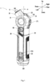
FIG. 1 is a perspective view of an example of the present application, where a working head is at a limit position; -
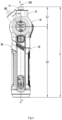
FIG. 2 is a perspective view of an example of the present application, where a working head is at a first position; -
FIG. 3 is a structural view of an example of the present application, where the working head is separately at the positions shown inFIGS. 1 and2 ; -
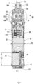
FIG. 4 is a sectional view of a power tool taken along line A-A ofFIG. 3 ; -
FIG. 5 is an enlarged view of a part structure inFigure 4 ; -
FIG. 6 is a schematic view of the internal structure of a power tool inFIG. 2 and a partial sectional view of a gearbox housing; -
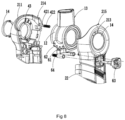
FIG. 7 is an exploded view of part of the structures of a power tool of an example of the present application and mainly shows a main housing, an output shaft housing, a positioning assembly, and a locking assembly; and -
FIG. 8 is an exploded view of part of the structures of a power tool of an example of the present application from another perspective and mainly shows a main housing, an output shaft housing, a positioning assembly, and a locking assembly. - In order that the preceding object, features, and advantages of the present application can be more apparent and easier to understand, examples of the present application are described below in detail in conjunction with drawings. Numerous specific details are set forth below to facilitate a thorough understanding of the present application. However, the present application can be implemented in many other manners than those described herein, and those skilled in the art may make similar modifications without departing from the connotation of the present application. Therefore, the present application is not limited by the examples disclosed below.
- In the description of the present application, the terms "joined", "connected", and "fixed" are to be understood in a broad sense unless otherwise expressly specified and limited. For example, the term "connected" may refer to "fixedly connected", "detachably connected", or integrated, may refer to "mechanically connected" or "electrically connected", or may refer to "connected directly", "connected indirectly through an intermediary", "connected inside two elements", or "interaction relations between two elements". For those of ordinary skill in the art, specific meanings of the preceding terms in the present application may be understood based on specific situations.
- In the present application, unless otherwise expressly specified and limited, when a first feature is described as "on" or "below" a second feature, the first feature and the second feature may be in direct contact or be in contact via another feature between the two features instead of being in direct contact. Moreover, when the first feature is described as "on", "above", or "over" the second feature, the first feature is right on, above, or over the second feature or the first feature is obliquely on, above, or over the second feature, or the first feature is simply at a higher level than the second feature. When the first feature is described as "under", "below", or "underneath" the second feature, the first feature is right under, below, or underneath the second feature or the first feature is obliquely under, below, or underneath the second feature, or the first feature is simply at a lower level than the second feature.
- The present application is described below in detail in conjunction with drawings and examples.
- To describe technical solutions of the present application clearly, "upper side", "lower side", "left side", "right side", "front side", and "rear side" as shown in
FIG. 1 are further defined. - As shown in
FIGS. 1 to 4 , apower tool 1 includes a workinghead 10, amain housing 20, and adrive mechanism 30. The workinghead 10 may output power directly or may be connected to another work accessory to output power. According to the working mode or output power of the workinghead 10, thepower tool 1 may be a corresponding tool, such as a screwdriver, a drill, or a wrench. The workinghead 10 is connected to themain housing 20 and rotates about afirst axis 101 relative to themain housing 20 under the action of an external force. The workinghead 10 is connected to thedrive mechanism 30 and outputs power under the action of thedrive mechanism 30. - The working
head 10 includes anoutput shaft 11. Theoutput shaft 11 is driven by thedrive mechanism 30 to rotate about anoutput axis 102. In this example, the screwdriver is used as an example, and amounting groove 111 to which different bits are mounted is further formed at the end of theoutput shaft 11. For example, themounting groove 111 is a standard hexagonal groove. In other alternative examples, for example, the power tool is the wrench, and a mounting head for mounting a sleeve is formed at or connected to the end of theoutput shaft 11. In other alternative examples, for example, the power tool is the drill, and a collet assembly for holding a drill bit is connected to the end of theoutput shaft 11. - The
main housing 20 includes agrip 22 and a connectingportion 21, where the connectingportion 21 is formed at or connected to an end of thegrip 22, and the connectingportion 21 is used for connecting the workinghead 10. In this example, themain housing 20 extends along athird axis 103 as a whole. The connectingportion 21 is located at the upper end of the main housing, that is to say, the workinghead 10 is connected to the upper end of themain housing 20. The connectingportion 21 is formed with a first accommodation space. Thegrip 22 is disposed below the connecting portion. Thegrip 22 is formed with a second accommodation space, and the first accommodation space communicates with the second accommodation space. Most of thedrive mechanism 30 is disposed in the second accommodation space formed by thegrip 22. It is to be understood that themain housing 20 is substantially in the shape of a straight tube. - As shown in
FIGS. 4 to 6 , thedrive mechanism 30 includes amotor 32 and a directcurrent power supply 33. In this example, themotor 32 includes a drive shaft rotatable about a drive axis. In this example, the drive axis coincides with thethird axis 103. In other alternative examples, the drive axis and thethird axis 103 are parallel to each other but do not coincide. In other alternative examples, a certain included angle exists between the drive axis and thethird axis 103. In this example, themotor 32 is specifically an electric motor, and theelectric motor 32 is used below instead of the motor in the subsequent description, but it does not serve as a limitation of the present invention. - In this example, the direct
current power supply 33 is specifically a battery or a battery pack. The battery or the battery pack mates with a corresponding power circuit to supply power to thepower tool 1. Those skilled in the art should understand that the battery is a built-in rechargeable battery or a replaceable standard battery. The directcurrent power supply 33 may also be the battery pack. In some examples, the directcurrent power supply 33 includes one battery. In some examples, the direct current power supply includes multiple batteries. It is to be understood that the number of cells in each battery varies with the nominal voltage and capacity of the battery, which does not limit the substantive content of the present application. In this example, the directcurrent power supply 33 has a nominal voltage less than or equal to 7.2 V. In this example, the direct current power supply has a nominal voltage less than or equal to 5 V. - In this example, the diameter of the grip is basically the same. In some examples, to increase the amount of power stored in the direct
current power supply 33 to prolong the service life thereof, the width of thegrip 22 at the corresponding position of the directcurrent power supply 33 increases. - A charging interface may be provided near the end of the
main housing 20, such as one or more of a universal serial bus (USB) interface, a Type-C interface, and a lighting interface. In this example, the charginginterface 231 is disposed at the bottom. The directcurrent power supply 33 is electrically connected to the charginginterface 231. In some examples, the directcurrent power supply 33 is the rechargeable battery removable from thegrip 22. The power tool is not limited to only using the directcurrent power supply 33 for power supply. With the corresponding rectification, filtering, and voltage regulation circuits, the power tool can be powered by not only the direct current power supply but also the alternating current power. - As shown in
FIGS. 1 to 3 andFIGS. 7 and8 , the workinghead 10 further includes a movingportion 12 and anoutput shaft housing 13. The movingportion 12 is formed on or connected to theoutput shaft housing 13. Theoutput shaft housing 13 is wrapped around the outer circumference of theoutput shaft 11. When theoutput shaft 11 rotates about theoutput axis 102, theoutput shaft housing 13 basically does not rotate with theoutput shaft 11. - The moving
portion 12 is connected to themain housing 20. In this example, the movingportion 12 is movably connected to the connectingportion 21 or is disposed in the first accommodation space. When the workinghead 10 rotates about thefirst axis 101 relative to themain housing 20, the movingportion 12 rotates with the workinghead 10 about thefirst axis 101. The connectingportion 21 on themain housing 20 is provided with arotation groove 211, theoutput shaft 11 protrudes from therotation groove 211, and the movingportion 12 is limited in therotation groove 211. The connectingportion 21 includes an arc-shaped or arc-like guide portion, and the workinghead 10 moves along the guide portion. In some examples, therotation groove 211 may be a closed groove body formed with a space in which the movingportion 12 is placed. In some examples, therotation groove 211 may be an open groove and has a limiting portion for limiting the movement of the movingportion 12. The limiting portion is provided so that therotation groove 211 is formed with a limiting groove with an opening in the first accommodation space. Theoutput shaft 11 protrudes from therotation groove 211, and the outer diameter of an end of theoutput shaft 11 connected to the movingportion 12 is approximately equal to the width of the rotation groove so that the end is engaged with therotation groove 211. Therotation groove 211 is disposed on a circumferential side (that is, a side around the first axis 101) of the connectingportion 21. In this example, the circumferential side of the connectingportion 21 is a curved surface, and the movingportion 12 is a curved surface having a shape corresponding to the circumferential side of the connecting portion. The surface of the movingportion 12 fits the inner surface of the connectingportion 21 so that the movingportion 12 is movable along therotation groove 211 on the connectingportion 21. - As shown in
FIGS. 4 to 6 , in this example, thepower tool 1 further includes aconnection assembly 50. Theconnection assembly 50 rotates the workinghead 10 about thefirst axis 101 relative to themain housing 11. Theconnection assembly 50 transmits the torque outputted by thedrive mechanism 30 to theoutput shaft 11. Thepower tool 1 includes a first transmission path. The first transmission path is a torque transmission path from thedrive mechanism 30 through theconnection assembly 50 to theoutput shaft 11. In this example, after theelectric motor 32 is powered on, the drive shaft of theelectric motor 32 rotates to generate torque. Thedrive mechanism 30 transmits the torque to theoutput shaft 11 through theconnection assembly 50. Theoutput shaft 11 outputs torque and the torque acts on a fastener, thereby forming a torque transmission path from thedrive mechanism 30 through theconnection assembly 50 to theoutput shaft 11, that is, the first transmission path. It is to be understood that when the workinghead 10 rotates about thefirst axis 101 relative to themain housing 20, an axis P of the first transmission path changes with the rotation of the workinghead 10, that is, the rotation of theoutput shaft 11. That is, the starting point of the axis P of the first transmission path is theelectric motor 32, and the end point of the axis P passes through theoutput shaft 11. Therefore, the axis P of the first transmission path is a curve or a straight line from theelectric motor 32 through theconnection assembly 50 to theoutput shaft 11. The direction of the first transmission path is from the starting point to the end point of the axis P of the first transmission path. - The
connection assembly 50 includes aninput portion 50a connected to thedrive mechanism 30 and anoutput portion 50b connected to theoutput shaft 11. Theinput portion 50a and theoutput portion 50b are two independent components connected to each other or different parts of the same component. When the workinghead 10 rotates about thefirst axis 101 relative to themain housing 20, the components in the first transmission path are allowed to deform or to be displaced along the direction of the first transmission path. That is to say, the component group in the first transmission path includes at least one component that is or includes a flexible structure, or at least two components in the component group in the first transmission path are in a floating connection. In this manner, when the workinghead 10 rotates about thefirst axis 101, the axis P of the first transmission path may bend or change in angle, thereby releasing the axial limit of the components in the first transmission path. In this example, theinput portion 50a and theoutput portion 50b are independent components connected to each other. When the workinghead 10 rotates about thefirst axis 101 relative to themain housing 20, at least one of thedrive mechanism 30, theinput portion 50a, theoutput portion 50b, and theoutput shaft 11 is allowed to be displaced along the direction of the first transmission path. In some examples, theinput portion 50a and theoutput portion 50b are different parts of the same component, for example, this component may be a flexible cable or a flexible shaft. When the workinghead 10 rotates about thefirst axis 101 relative to themain housing 20, theconnection assembly 50 is allowed to deform. - As an example of the present application, the
connection assembly 50 includes a universal joint 50c. In this example, the universal joint 50c includes a firstuniversal joint 51 and a second universal joint 52 connected to each other, that is, the universal joint 50c may be a duplex universal joint. The firstuniversal joint 51 may provide at least two orthogonal rotational degrees of freedom. The seconduniversal joint 52 may provide at least two orthogonal rotational degrees of freedom. - The first
universal joint 51 is used as an example for the description of the specific structure. The firstuniversal joint 51 includes afirst input portion 511, afirst output portion 513, and afirst holding portion 512. Thefirst holding portion 512 connects thefirst input portion 511 to thefirst output portion 513. In this example, thefirst holding portion 512 is a spherical retaining frame composed of aspherical base 5121 and acorresponding ball head 5122. Any one of thefirst input portion 511 and thefirst output portion 513 forms or is connected to thespherical base 5121, and the other one of thefirst input portion 511 and thefirst output portion 513 forms or is connected to theball head 5122. In this example, thedrive mechanism 30 is connected to an end of thefirst input portion 511, and thespherical base 5121 is formed at the other end of thefirst input portion 511. Theball head 5122 is formed at an end of thefirst output portion 513, and the seconduniversal joint 52 is connected to the other end of thefirst output portion 513. Rolling balls are disposed in theball head 5122 to keep theball head 5122 in thespherical base 5121 and enable the first universal joint 51 to achieve variable-angle power transmission. The dimension of part of thefirst input portion 511, thefirst output portion 513, and thefirst holding portion 512 with the largest radial dimension is defined as the maximum radial dimension R1 of the firstuniversal joint 51. In this example, the diameter of thespherical base 5121 is the maximum radial dimension R1 of the firstuniversal joint 51. The ratio of the maximum radial dimension R1 of the first universal joint 51 to the outer diameter dimension R2 of theelectric motor 32 is greater than or equal to 0.1 and less than or equal to 0.9. It is to be explained that when theelectric motor 32 is an inrunner motor, the outer diameter of theelectric motor 32 is the diameter of stator laminations. When theelectric motor 32 is an outrunner motor, the outer diameter of theelectric motor 32 is the diameter of a rotor sleeve. In some examples, the ratio of the maximum radial dimension R1 of the first universal joint 51 to the outer diameter dimension R2 of theelectric motor 32 is greater than or equal to 0.1 and less than or equal to 0.7. In some examples, the ratio of the maximum radial dimension R1 of the first universal joint 51 to the outer diameter dimension R2 of theelectric motor 32 is greater than or equal to 0.1 and less than or equal to 0.6. In some examples, the ratio of the maximum radial dimension R1 of the first universal joint 51 to the outer diameter dimension R2 of theelectric motor 32 is greater than or equal to 0.2 and less than or equal to 0.9. - In this example, the
ball head 5122 forms a floating connection with thespherical base 5121. When the workinghead 10 rotates around thefirst axis 101 relative to themain housing 20, theball head 5122 floats relative to thespherical base 5121, that is to say, there is a gap between theball head 5122 and thespherical base 5121 so that theball head 5122 can move relative to thespherical base 5121 in the direction of the first transmission path. Theball head 5122 can be understood as a part in the first transmission path that can be displaced along the direction of the first transmission path. - As can be seen from the related art, the outer diameter of the electric motor affects the performance of the electric motor. In the first transmission path, the
connection assembly 50 needs to ensure sufficient strength so that the torque can be transmitted to theoutput shaft 11. In this manner, breaking or unspecified deformation of the connection assembly can be avoided during torque transmission. The increase of the diameter or volume of theconnection assembly 50 improves the strength of the connection assembly, but the feel of the product are affected and the cost of the product is increased. Therefore, a relatively balanced and proper relationship is required between theconnection assembly 50 and theelectric motor 32. The ratio of the maximum radial dimension R1 of the first universal joint to the outer diameter dimension R2 of theelectric motor 32 is defined to be greater than or equal to 0.1 and less than or equal to 0.9. In some examples, the ratio of the maximum radial dimension R1 of the first universal joint to the outer diameter dimension R2 of theelectric motor 32 is defined to be greater than or equal to 0.1 and less than or equal to 0.7. In some examples, the ratio of the maximum radial dimension R1 of the first universal joint to the outer diameter dimension R2 of theelectric motor 32 is defined to be greater than or equal to 0.2 and less than or equal to 0.7 so that the strength of theconnection assembly 50 can be ensured during torque transmission. The overall compactness of the power tool is improved, providing a better use effect. - In some alternative examples, the number of universal joints included in the connection assembly is not limited. The number of universal joints may be one or more than two, which does not limit the substantive content of the present application.
- In some alternative examples, the first
universal joint 51 is a cross shaft universal joint. The first holding portion is a cross shaft part connecting the first input portion to the first output portion. The diameter of the first holding portion is the diameter of the smallest circle enclosing the cross shaft part. - In this example, the first
universal joint 51 and the seconduniversal joint 52 are spherical universal joints with the same structure. In some examples, the first universal joint and the second universal joint may have the same structure but different dimensions. In some examples, the first universal joint and the second universal joint may have different structures and different dimensions. It is to be understood that when the universal joint 50c includes two or more single universal joints, the maximum radial dimension R1 of the universal joint 50c is the maximum value among the radial dimensions of the input portion, the output portion, and the holding portion of each single universal joint in the universal joint 50c. - In this example, the
connection assembly 50 further includes anintermediate piece 53. Theintermediate piece 53 is used for displaying the logo or special appearance of the product, a product shape, or product information. For example, theintermediate piece 53 is used for indicating the rotational angle of the workinghead 10 about thefirst axis 101 or the rotational speed of theoutput shaft 11. In some examples, a state display unit is disposed on theintermediate piece 53. The state display unit includes a liquid crystal display (LCD)/light-emitting diode (LED) display screen, a buzzer, a component like a light-emitting diode, or another component with a prompt function, and the state display unit is used for performing a state display or giving a prompt when the power tool has an abnormal working state or a low battery. A specific prompt mode varies with the definition and requirement of the product. It is to be understood that the specific prompt mode has been fully disclosed to those skilled in the art. It is to be understood that the intermediate piece does not belong to the components of the universal joint 50c, and the dimension of the intermediate piece does not belong to the dimension of the universal joint 50c. - As shown in
FIGS. 1 to 3 , the workinghead 10 includes a limit position and a first position. The limit position is a position for making the workinghead 10 move about thefirst axis 101 to the limit, and the first position is a position for making the axis of theinput portion 50a parallel to or coincident with the axis of theoutput portion 50b. In this example, the axis of theinput portion 50a coincides with the drive axis of theelectric motor 32 and thethird axis 103. The axis of theoutput portion 50b coincides with theoutput axis 102 of theoutput shaft 11. As shown inFIG. 2 , when the workinghead 10 is at the first position, thethird axis 103 coincides with theoutput axis 102. The included angle α between the axis of theinput portion 50a, that is, thethird axis 103 and the axis of theoutput portion 50b, that is, theoutput axis 102, is 0 degrees. As shown inFIG. 1 , when the workinghead 10 is at the limit position, the included angle α between the axis of theinput portion 50a, that is, thethird axis 103 and the axis of theoutput portion 50b, that is, theoutput axis 102, is less than or equal to 85 degrees. In some examples, when the workinghead 10 is at the limit position, α is less than or equal to 70 degrees, 60 degrees, or 50 degrees. The included angle α between the axis of theinput portion 50a, that is, thethird axis 103 and the axis of theoutput portion 50b, that is, theoutput axis 102, when the workinghead 10 is at the limit position is limited so that the output torque of theoutput shaft 11 is ensured, and the torque transmission efficiency of the connection assembly is ensured. When the workinghead 10 is at the first position, theconnection assembly 50 has the maximum torque transmission efficiency. The torque transmission efficiency of theconnection assembly 50 when the workinghead 10 is at the limit position is lower than the torque transmission efficiency of theconnection assembly 50 when the workinghead 10 is at the first position. In this example, at the limit position, the included angle α between the axis of theinput portion 50a, that is, thethird axis 103, and the axis of theoutput portion 50b, that is, theoutput axis 102, is less than or equal to 85 degrees so that the ratio of the output torque of theoutput shaft 11 when the workinghead 10 is at the limit position to the output torque of theoutput shaft 11 when the workinghead 10 is at the first position is greater than or equal to 0.5 and less than or equal to 1, thereby ensuring the torque transmission efficiency of the connection assembly. In some examples, the ratio of the output torque of theoutput shaft 11 when the workinghead 10 is located at the limit position to the output torque of theoutput shaft 11 when the workinghead 10 is located at the first position is greater than or equal to 0.6 and less than or equal to 1. In this example, when the workinghead 10 is located at the first position, the output torque of theoutput shaft 11 is greater than or equal to 2.5 N·m. - In this example, the limit position includes a first limit position for making the working
head 10 move along a first direction about thefirst axis 101 to the limit. Multiple positions for locking the workinghead 10 may further be included between the first position and the first limit position. As shown inFIGS. 7 and8 , thepower tool 1 further includes apositioning assembly 40. Thepositioning assembly 40 is used for positioning the rotational position of the workinghead 10 about thefirst axis 101 relative to themain housing 20. Thepositioning assembly 40 is disposed between the movingportion 12 and the connectingportion 21 and couples the movingportion 12 to the connectingportion 21 to stop the workinghead 10 at a set position. - The
positioning assembly 40 includes abase 41, a positioningmember 42, and apositioning groove 43.Multiple positioning grooves 43 are provided. Themultiple positioning grooves 43 are disposed on the inner side of the connectingportion 21. In this example,multiple angle indicators 213 are disposed on the outer side of the connectingportion 21, that is, a side observable by the user. The number of theangle indicators 213 is the same as the number of thepositioning grooves 43. Thebase 41 is disposed on the workinghead 10. In this example, thebase 41 is disposed on theoutput shaft housing 13. Thebase 41 extends along the direction of thefirst axis 101. The positioningmember 42 connects the movingportion 12 to the connectingportion 21. An end of the positioningmember 42 is connected to thebase 41, and the other end of the positioningmember 42 is clutchably connected to thepositioning groove 43. The positioningmember 42 is movable in the base 41 relative to the movingportion 12. The movement of the positioningmember 42 is caused by the rotation of the workinghead 10 about the direction of thefirst axis 101, and the shape of themultiple positioning grooves 43 corresponds to the shape of the positioningmember 42. Thepositioning groove 43 is connected to the positioningmember 42 to position the workinghead 10. The position of each positioninggroove 43 corresponds to a different rotational angle of the workinghead 10. - When the working
head 10 rotates from a certain angle to another angle, the positioningmember 42 moves from acorresponding positioning groove 43 into the thebase 41 and then moves from the base 41 to anotherpositioning groove 43. In this example, the positioningmember 42 includes a rollingball 421 and atelescopic member 422. When the workinghead 10 rotates, the rollingball 421 moves in anadjacent positioning groove 43 to a groove wall and is then pressed by the groove wall, and the rollingball 421 biases thetelescopic member 422. When the rollingball 421 enters onepositioning groove 43, thetelescopic member 422 supports the rollingball 421 to keep the rollingball 421 in thepositioning groove 43. - As shown in
FIGS. 4 to 7 , thepower tool 1 further includes a lockingassembly 60 for positioning the rotational position of the workinghead 10 about thefirst axis 101 relative to themain housing 20. It is to be understood that the limiting force provided by thepositioning assembly 40 is not enough to ensure that the workinghead 10 and themain housing 20 do not move relative to each other during operation. That is to say, when thepositioning assembly 40 completes the positioning, the relative motion between the workinghead 10 and themain housing 20 can be restricted, but when the torque output work is performed, the positioning state of thepositioning assembly 40 is easily destroyed. The lockingassembly 60 can provide a locking force sufficient to keep the workinghead 10 and themain housing 20 in a relatively locked state stably during operation. - The locking
assembly 60 includesfirst teeth 61,second teeth 62, and atrigger 63. Thefirst teeth 61 and thesecond teeth 62 are engaged with each other. Thefirst teeth 61 are formed around the circumferential direction of the workinghead 10. In this example, thefirst teeth 61 are disposed on theoutput shaft housing 13 and are disposed on the outer circumference of a first throughhole 131. Thetrigger 63 is partially disposed outside themain housing 20 and is used for the user to trigger. Thetrigger 63 is connected to thesecond teeth 62. Thetrigger 63 includes a locked position and an unlocked position, where when thetrigger 63 is at the locked position, thefirst teeth 61 and thesecond teeth 62 are engaged with each other. When thetrigger member 63 is triggered to move to the unlocked position, thesecond teeth 62 are displaced and disengaged from thefirst teeth 61, and at this time, the workinghead 10 can rotate about thefirst axis 101 relative to themain housing 20. Thetrigger 63 is disposed on the same side as a torqueregulation operating member 173 and a switching operating member. Thetrigger 63 is located at the upper position of the grip. Thetrigger 63 is disposed at a position where the thumb can operate when the palm of the user holds the grip. - In this example, the locking
assembly 60 further includes a biasingelement 64 connected to thetrigger 63. The biasingelement 64 provides a biasing force to move thetrigger 63 from the unlocked position to the locked position, that is, a biasing force to move thesecond teeth 62 toward thefirst teeth 61. It is to be understood that the number of thepositioning grooves 43 in thepositioning assembly 40 corresponds to the number of thefirst teeth 61. - In some examples, the limit position includes a second limit position for making the working
head 10 move along a second direction about thefirst axis 101 to the limit. The first limit position and the second limit position are located on two sides of the first position. The first position is an intermediate position, the first limit position is in front of the first position, and the second limit position is behind the first position. The second limit position and the first limit position may be arranged symmetrically with respect to the first position, or the second limit position may be closer to the first position than the first limit position. - As shown in
FIGS. 4 to 6 , thedrive mechanism 30 further includes atransmission assembly 31. Thetransmission assembly 31, theelectric motor 32, and the directcurrent power supply 33 are connected from top to bottom in sequence. In this example, thetransmission assembly 31, theelectric motor 32, and the directcurrent power supply 33 are disposed in the second accommodation space, or at least most of thetransmission assembly 31, theelectric motor 32, and the directcurrent power supply 33 are disposed in the second accommodation space. - The
transmission assembly 31 is used for transmitting power outputted by theelectric motor 32 to theoutput shaft 11. Thetransmission assembly 31 is disposed between theoutput shaft 11 and theelectric motor 32, and thetransmission assembly 31 is at least partially or entirely disposed in thegrip 22 and may be at least partially disposed in the connectingportion 21. In this example, thetransmission assembly 31 adopts a planet gear deceleration mechanism. Thetransmission assembly 31 includes aplanetary gearset 311 of three stages or more than three stages and agearbox housing 312. An internal tooth structure is disposed on the inner side of thegearbox housing 312. Since the working principle of the planet gear deceleration mechanism and the principle of deceleration generated by the transmission assembly or the speed regulation principle of the planet gear have been fully disclosed to those skilled in the art, a detailed description is omitted herein for the brevity of the description. - As shown in
FIGS. 3 and4 , the distance between the rear end of the main housing and the front end of the output shaft when the workinghead 10 is at the first position is defined as the maximum distance L. The distance between thefirst axis 101 and the front end of theoutput shaft 11 is L1. It is to be explained that in this example, a clamping portion for clamping the accessory is formed on a shaft body of the output shaft, and the front end of the output shaft is the front end of the shaft body. In some examples, the output shaft includes the shaft body and the clamping portion, the clamping portion is fixedly connected to the shaft body, and the front end of the output shaft is the frontmost part of the shaft body and the clamping portion. In some examples, the output shaft includes the shaft body and the clamping portion, and the clamping portion is detachably connected to the shaft body. That is to say, after the clamping portion of the power tool is detached, when the shaft body can still drive the accessory to work, the front end of the output shaft is the front end of the shaft body. In this example, the ratio of the distance L1 between thefirst axis 101 and the front end of theoutput shaft 11 to the maximum distance L is greater than or equal to 0.1 and less than or equal to 0.4. In some examples, the ratio of the distance L1 between the first axis and the front end of the output shaft to the maximum distance L is greater than or equal to 0.1 and less than or equal to 0.35. In some examples, the ratio of the distance L1 between the first axis and the front end of the output shaft to the maximum distance L is greater than or equal to 0.1 and less than or equal to 0.3 so that the working head is more suitable for a narrow space. In this example, the distance L1 between the first axis and the front end of the output shaft is less than or equal to 65 mm. In some examples, the distance L1 between the first axis and the front end of the output shaft is less than or equal to 60 mm. In some examples, the distance L1 between the first axis and the front end of the output shaft is less than or equal to 55 mm. In some examples, the distance L1 between the first axis and the front end of the output shaft is less than or equal to 50 mm. - In some examples, the distance L3 between the
first axis 101 and the rear end of the main housing is less than or equal to 230 mm. In some examples, the distance L3 between thefirst axis 101 and the rear end of the main housing is less than or equal to 210 mm. In some examples, the distance L3 between thefirst axis 101 and the rear end of the main housing is less than or equal to 195 mm. - In this example, the direct
current power supply 33 is built in the main housing. When the workinghead 10 is at the first position, the ratio of the length L2 of the directcurrent power supply 33 to the maximum distance L between the rear end of the main housing and the front end of the output shaft is greater than or equal to 0.1 and less than or equal to 0.6. In some examples, when the workinghead 10 is at the first position, the ratio of the length L2 of the directcurrent power supply 33 to the maximum distance L between the rear end of the main housing and the front end of the output shaft is greater than or equal to 0.1 and less than or equal to 0.5. In some examples, when the workinghead 10 is at the first position, the ratio of the length L2 of the directcurrent power supply 33 to the maximum distance L between the rear end of the main housing and the front end of the output shaft is greater than or equal to 0.1 and less than or equal to 0.4 so that the whole power tool is compact. The length L2 of the directcurrent power supply 33 is the length of the battery or battery pack of the directcurrent power supply 33 along the direction of thethird axis 103. In this example, the weight of the power tool is less than or equal to 400 g. In some examples, the directcurrent power supply 33 is a battery pack, the battery pack is detachably mounted in the main housing, and the directcurrent power supply 33 is partially mounted in the main housing. In this case, the length L2 of the directcurrent power supply 33 is the length of the battery pack. - As shown in
FIGS. 1 to 3 andFIGS. 7 and8 , awindow portion 14 is disposed in themain housing 20 and used for displaying the internal structure of thepower tool 1. In this example, thewindow portion 14 is disposed on the connectingportion 21, and the position of thewindow portion 14 is opposite to the position of theconnection assembly 50 so that part of the structure of theconnection assembly 50 is displayed in the window portion. - As shown in
FIGS. 1 to 3 , thepower tool 1 further includes a switch assembly including at least two switches that are used for controlling different functions of the electric motor and a controller. The switch assembly includes operating members and corresponding switch elements. The operating members include a mainswitch operating member 171, the torqueregulation operating member 173, and the switching operating member. The mainswitch operating member 171 corresponds to a main switch and is used for controlling the start and stop of theelectric motor 32. The torqueregulation operating member 173 and the switching operating member send different signals to the controller to control the output torque of theoutput shaft 11 and switch a forward rotation state and a reverse rotation state of theelectric motor 32. The mainswitch operating member 171 is disposed at the joint of thegrip 22 and the connectingportion 21. In this example, the mainswitch operating member 171 is disposed on a side adjacent to thewindow portion 14. The switching operating member is coupled to the mainswitch operating member 171. The torqueregulation operating member 173 is disposed on thegrip 22. In some examples, the torqueregulation operating member 173 is disposed near the lower end of thegrip 22. The torqueregulation operating member 173 is disposed on the same side as thewindow portion 14. That is to say, the mainswitch operating member 171 and the torqueregulation operating member 173 are disposed on adjacent sides. It is to be understood that the mainswitch operating member 171 and the torqueregulation operating member 173 are staggered at an angle on themain housing 20 around thethird axis 103. In this example, a torque indicator light 1721 is disposed near the torqueregulation operating member 173. Different display states of the torque indicator light 1721 indicate different output torque. Thetorque indicator light 1721 and the torqueregulation operating member 173 are disposed on the same side of thegrip 22. In other alternative examples, the switching operating member and the mainswitch operating member 171 are disposed independently and disposed on the same side of thegrip 22. - In this example, the torque
regulation operating member 173 is integrated with a locking function, or a lock is disposed near the torqueregulation operating member 173. That is, the lock can control the connection and disconnection of the electrical connection between the electric motor and the direct current power supply. - The controller is disposed on a
control circuit board 16. Thecontrol circuit board 16 includes a printed circuit board (PCB) and a flexible printed circuit (FPC) board. The controller uses a dedicated control chip, for example, a single-chip microcomputer and a microcontroller unit (MCU). - The operating members are connected to the corresponding switches. The switches are electrically connected to the controller. According to different signals sent by the switches, the controller performs corresponding control actions on the electric motor.
- The
control circuit board 16 is electrically connected to thedrive mechanism 30. Thecontrol circuit board 16 is disposed in thegrip 22 and is parallel or basically parallel to thedrive mechanism 30 or thethird axis 103. Being basically parallel refers to the case where the included angle between thecontrol circuit board 16 and thedrive mechanism 30 or thethird axis 103 is less than or equal to 10 degrees. - As shown in
FIG. 2 , thepower tool 1 further includes alighting assembly 15. Thelighting assembly 15 is disposed on the workinghead 10 and provides light for illuminating a working region. Thelighting assembly 15 rotates with the workinghead 10 about thefirst axis 101 and always provides light for illuminating the working position of theoutput shaft 11. Thelighting assembly 15 includes a lighting element for emitting light, and the lighting element is disposed in theoutput shaft housing 13 and located on a side of theoutput shaft 11. In other alternative examples, the lighting element is disposed around the output shaft. - As shown in
FIGS. 4 to 8 , in this example, the connectingportion 21 includes a left connectingportion 214 and aright connecting portion 215 that are assembled with each other. Theright connecting portion 215 is integrally formed with thegrip 22. That is to say, the basicallycylindrical grip 22 is integrally formed with theright connecting portion 215. Theleft connecting portion 214 is detachably connected to theright connecting portion 215, so as to increase the strength of themain housing 20. The bottom of themain housing 20 further includes alower cover 23 connected to the lower opening of theright connecting portion 215. The charginginterface 231 is disposed on thelower cover 23. - To make the main housing more comfortable for the user to hold, the outer circumference of the main housing is covered with soft materials, such as rubber, silicone, and soft plastic. In this example, the soft materials are disposed near the grip and the working head.
Claims (15)
- A power tool (1), comprising:a main housing (20) provided with an accommodation space;a drive mechanism at least partially accommodated in the accommodation space and comprising a motor (32);a working head (10) comprising an output shaft (11), wherein the output shaft is driven by the drive mechanism to rotate about an output axis (102); anda connection assembly (50) comprising an input portion (50a) connected to the drive mechanism and an output portion (50b) connected to the output shaft, wherein the connection assembly rotates the working head around a first axis (101) relative to the main housing;wherein the power tool comprises a first transmission path, the first transmission path is a torque transmission path from the drive mechanism through the connection assembly to the output shaft, and at least a component in the first transmission path are allowed to deform or to be displaced along a direction of the first transmission path when the working head rotates about the first axis relative to the main housing.
- The power tool of claim 1, wherein the working head comprises a limit position where the working head moves to a limit around the first axis, and an included angle α between an axis of the input portion and an axis of the output portion is less than or equal to 85 degrees when the working head is located at the limit position.
- The power tool of claim 1, wherein the working head comprises a limit position where the working head moves to a limit around the first axis, and an included angle α between an axis of the input portion and an axis of the output portion is less than or equal to 70 degrees when the working head is located at the limit position.
- The power tool of claim 2, wherein the working head further comprises a first position where the axis of the input portion is parallel to or coincident with the axis of the output portion.
- The power tool of claim 4, wherein the limit position comprises a first limit position where the working head moves to a limit along a first direction around the first axis, and the first limit position is located on a side of the first position.
- The power tool of claim 5, wherein the limit position further comprises a second limit position where the working head moves to a limit along a second direction opposite to the first direction around the first axis, and the first limit position and the second limit position are located on two sides of the first position.
- The power tool of claim 4, wherein a ratio of output torque of the output shaft when the working head is located at the limit position to output torque of the output shaft when the working head is located at the first position is greater than or equal to 0.5 and less than or equal to 1.
- The power tool of claim 4, wherein when the working head is located at the first position, output torque of the output shaft is greater than or equal to 2.5 N m.
- The power tool of claim 1, wherein a ratio of a distance L1 between the first axis and a front end of the output shaft to a maximum distance L between a rear end of the main housing and the front end of the output shaft is greater than or equal to 0.1 and less than or equal to 0.4.
- The power tool of claim 9, wherein the ratio of the distance L1 between the first axis and the front end of the output shaft to the maximum distance L between the rear end of the main housing and the front end of the output shaft is greater than or equal to 0.1 and less than or equal to 0.3.
- The power tool of claim 1, wherein the drive mechanism comprises a direct current power supply (33).
- The power tool of claim 11, wherein the direct current power supply comprises a battery and has a nominal voltage less than or equal to 7.2 V.
- The power tool of claim 11, wherein a ratio of a length L2 of the direct current power supply to a maximum distance L between a rear end of the main housing and a front end of the output shaft is greater than or equal to 0.1 and less than or equal to 0.6.
- The power tool of claim 1, wherein when the working head rotates about the first axis relative to the main housing, the connection assembly is allowed to deform.
- The power tool of claim 1, wherein when the working head rotates about the first axis relative to the main housing, at least one of the drive mechanism, the input portion, the output portion, and the output shaft is allowed to be displaced along the direction of the first transmission path.
Applications Claiming Priority (3)
| Application Number | Priority Date | Filing Date | Title |
|---|---|---|---|
| CN202320583788.8U CN219649812U (en) | 2023-03-22 | 2023-03-22 | Electric tool |
| CN202310286394.0A CN118682707A (en) | 2023-03-22 | 2023-03-22 | Power Tools |
| CN202320585598.XU CN219649813U (en) | 2023-03-22 | 2023-03-22 | Electric tool |
Publications (2)
| Publication Number | Publication Date |
|---|---|
| EP4434677A1 true EP4434677A1 (en) | 2024-09-25 |
| EP4434677B1 EP4434677B1 (en) | 2025-01-01 |
Family
ID=87060358
Family Applications (1)
| Application Number | Title | Priority Date | Filing Date |
|---|---|---|---|
| EP23182556.3A Active EP4434677B1 (en) | 2023-03-22 | 2023-06-30 | Power tool |
Country Status (2)
| Country | Link |
|---|---|
| EP (1) | EP4434677B1 (en) |
| CA (1) | CA3207756A1 (en) |
Citations (4)
| Publication number | Priority date | Publication date | Assignee | Title |
|---|---|---|---|---|
| US20070259723A1 (en) * | 2004-01-23 | 2007-11-08 | Bertani Romolo L | Multidirectional Transmission |
| DE102013204225A1 (en) * | 2013-03-12 | 2014-09-18 | Robert Bosch Gmbh | Hand tool with a drive shaft for rotating a tool holder |
| US20220324086A1 (en) * | 2021-04-13 | 2022-10-13 | Snap-On Incorporated | Flexible head joints for cordless ratchet tools |
| WO2023160348A1 (en) * | 2022-02-22 | 2023-08-31 | 南京泉峰科技有限公司 | Electric tool |
-
2023
- 2023-06-30 EP EP23182556.3A patent/EP4434677B1/en active Active
- 2023-07-27 CA CA3207756A patent/CA3207756A1/en active Pending
Patent Citations (4)
| Publication number | Priority date | Publication date | Assignee | Title |
|---|---|---|---|---|
| US20070259723A1 (en) * | 2004-01-23 | 2007-11-08 | Bertani Romolo L | Multidirectional Transmission |
| DE102013204225A1 (en) * | 2013-03-12 | 2014-09-18 | Robert Bosch Gmbh | Hand tool with a drive shaft for rotating a tool holder |
| US20220324086A1 (en) * | 2021-04-13 | 2022-10-13 | Snap-On Incorporated | Flexible head joints for cordless ratchet tools |
| WO2023160348A1 (en) * | 2022-02-22 | 2023-08-31 | 南京泉峰科技有限公司 | Electric tool |
Also Published As
| Publication number | Publication date |
|---|---|
| EP4434677B1 (en) | 2025-01-01 |
| CA3207756A1 (en) | 2025-07-07 |
Similar Documents
| Publication | Publication Date | Title |
|---|---|---|
| US12420386B2 (en) | Power tool | |
| US10906163B2 (en) | Power tool | |
| CN108406663B (en) | Electric tool | |
| JP7210291B2 (en) | electric driver drill | |
| CN203266596U (en) | Electric tool | |
| CN116638480B (en) | Electric tool | |
| US20130062088A1 (en) | Impact tool | |
| US10286529B2 (en) | Screw-tightening power tool | |
| US20120152580A1 (en) | Hand power tool and drive train | |
| CN220699520U (en) | Hand-held electric tool | |
| JP7745031B2 (en) | Electric Ratchet Wrench | |
| US12304051B2 (en) | Power tool | |
| JP2017209760A (en) | Electric tool | |
| CA2728582A1 (en) | An accessory and charging system for a rechargeable hand-held electrical device | |
| CN220762522U (en) | Power tool having a coupling mechanism for engaging a first housing portion and a second housing portion | |
| EP4434677B1 (en) | Power tool | |
| CN115741599B (en) | Power tool and control method thereof | |
| CN219649813U (en) | Electric tool | |
| CN219649812U (en) | Electric tool | |
| JP2007015045A (en) | Cordless power tool | |
| CN118682707A (en) | Power Tools | |
| JP2024152685A (en) | Electric Ratchet Wrench | |
| CN117601077A (en) | Impact tool | |
| JP2019171504A (en) | Electric tool | |
| US10518399B2 (en) | Clutch device and power tool with clutch device |
Legal Events
| Date | Code | Title | Description |
|---|---|---|---|
| PUAI | Public reference made under article 153(3) epc to a published international application that has entered the european phase |
Free format text: ORIGINAL CODE: 0009012 |
|
| STAA | Information on the status of an ep patent application or granted ep patent |
Free format text: STATUS: REQUEST FOR EXAMINATION WAS MADE |
|
| 17P | Request for examination filed |
Effective date: 20240724 |
|
| AK | Designated contracting states |
Kind code of ref document: A1 Designated state(s): AL AT BE BG CH CY CZ DE DK EE ES FI FR GB GR HR HU IE IS IT LI LT LU LV MC ME MK MT NL NO PL PT RO RS SE SI SK SM TR |
|
| GRAP | Despatch of communication of intention to grant a patent |
Free format text: ORIGINAL CODE: EPIDOSNIGR1 |
|
| STAA | Information on the status of an ep patent application or granted ep patent |
Free format text: STATUS: GRANT OF PATENT IS INTENDED |
|
| INTG | Intention to grant announced |
Effective date: 20241015 |
|
| GRAS | Grant fee paid |
Free format text: ORIGINAL CODE: EPIDOSNIGR3 |
|
| GRAA | (expected) grant |
Free format text: ORIGINAL CODE: 0009210 |
|
| STAA | Information on the status of an ep patent application or granted ep patent |
Free format text: STATUS: THE PATENT HAS BEEN GRANTED |
|
| AK | Designated contracting states |
Kind code of ref document: B1 Designated state(s): AL AT BE BG CH CY CZ DE DK EE ES FI FR GB GR HR HU IE IS IT LI LT LU LV MC ME MK MT NL NO PL PT RO RS SE SI SK SM TR |
|
| REG | Reference to a national code |
Ref country code: GB Ref legal event code: FG4D |
|
| REG | Reference to a national code |
Ref country code: DE Ref legal event code: R096 Ref document number: 602023001573 Country of ref document: DE |
|
| REG | Reference to a national code |
Ref country code: CH Ref legal event code: EP |
|
| REG | Reference to a national code |
Ref country code: IE Ref legal event code: FG4D |
|
| REG | Reference to a national code |
Ref country code: LT Ref legal event code: MG9D |
|
| REG | Reference to a national code |
Ref country code: NL Ref legal event code: MP Effective date: 20250101 |
|
| REG | Reference to a national code |
Ref country code: AT Ref legal event code: MK05 Ref document number: 1755747 Country of ref document: AT Kind code of ref document: T Effective date: 20250101 |
|
| PG25 | Lapsed in a contracting state [announced via postgrant information from national office to epo] |
Ref country code: NL Free format text: LAPSE BECAUSE OF FAILURE TO SUBMIT A TRANSLATION OF THE DESCRIPTION OR TO PAY THE FEE WITHIN THE PRESCRIBED TIME-LIMIT Effective date: 20250101 |
|
| PG25 | Lapsed in a contracting state [announced via postgrant information from national office to epo] |
Ref country code: FI Free format text: LAPSE BECAUSE OF FAILURE TO SUBMIT A TRANSLATION OF THE DESCRIPTION OR TO PAY THE FEE WITHIN THE PRESCRIBED TIME-LIMIT Effective date: 20250101 |
|
| PG25 | Lapsed in a contracting state [announced via postgrant information from national office to epo] |
Ref country code: PL Free format text: LAPSE BECAUSE OF FAILURE TO SUBMIT A TRANSLATION OF THE DESCRIPTION OR TO PAY THE FEE WITHIN THE PRESCRIBED TIME-LIMIT Effective date: 20250101 |
|
| PGFP | Annual fee paid to national office [announced via postgrant information from national office to epo] |
Ref country code: DE Payment date: 20250507 Year of fee payment: 3 |
|
| PG25 | Lapsed in a contracting state [announced via postgrant information from national office to epo] |
Ref country code: ES Free format text: LAPSE BECAUSE OF FAILURE TO SUBMIT A TRANSLATION OF THE DESCRIPTION OR TO PAY THE FEE WITHIN THE PRESCRIBED TIME-LIMIT Effective date: 20250101 |
|
| PG25 | Lapsed in a contracting state [announced via postgrant information from national office to epo] |
Ref country code: IS Free format text: LAPSE BECAUSE OF FAILURE TO SUBMIT A TRANSLATION OF THE DESCRIPTION OR TO PAY THE FEE WITHIN THE PRESCRIBED TIME-LIMIT Effective date: 20250501 Ref country code: NO Free format text: LAPSE BECAUSE OF FAILURE TO SUBMIT A TRANSLATION OF THE DESCRIPTION OR TO PAY THE FEE WITHIN THE PRESCRIBED TIME-LIMIT Effective date: 20250401 |
|
| PG25 | Lapsed in a contracting state [announced via postgrant information from national office to epo] |
Ref country code: HR Free format text: LAPSE BECAUSE OF FAILURE TO SUBMIT A TRANSLATION OF THE DESCRIPTION OR TO PAY THE FEE WITHIN THE PRESCRIBED TIME-LIMIT Effective date: 20250101 |
|
| PG25 | Lapsed in a contracting state [announced via postgrant information from national office to epo] |
Ref country code: LV Free format text: LAPSE BECAUSE OF FAILURE TO SUBMIT A TRANSLATION OF THE DESCRIPTION OR TO PAY THE FEE WITHIN THE PRESCRIBED TIME-LIMIT Effective date: 20250101 Ref country code: PT Free format text: LAPSE BECAUSE OF FAILURE TO SUBMIT A TRANSLATION OF THE DESCRIPTION OR TO PAY THE FEE WITHIN THE PRESCRIBED TIME-LIMIT Effective date: 20250502 |
|
| PGFP | Annual fee paid to national office [announced via postgrant information from national office to epo] |
Ref country code: FR Payment date: 20250508 Year of fee payment: 3 |
|
| PG25 | Lapsed in a contracting state [announced via postgrant information from national office to epo] |
Ref country code: GR Free format text: LAPSE BECAUSE OF FAILURE TO SUBMIT A TRANSLATION OF THE DESCRIPTION OR TO PAY THE FEE WITHIN THE PRESCRIBED TIME-LIMIT Effective date: 20250402 Ref country code: BG Free format text: LAPSE BECAUSE OF FAILURE TO SUBMIT A TRANSLATION OF THE DESCRIPTION OR TO PAY THE FEE WITHIN THE PRESCRIBED TIME-LIMIT Effective date: 20250101 |
|
| PG25 | Lapsed in a contracting state [announced via postgrant information from national office to epo] |
Ref country code: AT Free format text: LAPSE BECAUSE OF FAILURE TO SUBMIT A TRANSLATION OF THE DESCRIPTION OR TO PAY THE FEE WITHIN THE PRESCRIBED TIME-LIMIT Effective date: 20250101 |
|
| PG25 | Lapsed in a contracting state [announced via postgrant information from national office to epo] |
Ref country code: CZ Free format text: LAPSE BECAUSE OF FAILURE TO SUBMIT A TRANSLATION OF THE DESCRIPTION OR TO PAY THE FEE WITHIN THE PRESCRIBED TIME-LIMIT Effective date: 20250101 |
|
| PG25 | Lapsed in a contracting state [announced via postgrant information from national office to epo] |
Ref country code: SE Free format text: LAPSE BECAUSE OF FAILURE TO SUBMIT A TRANSLATION OF THE DESCRIPTION OR TO PAY THE FEE WITHIN THE PRESCRIBED TIME-LIMIT Effective date: 20250101 |
|
| REG | Reference to a national code |
Ref country code: DE Ref legal event code: R097 Ref document number: 602023001573 Country of ref document: DE |
|
| PG25 | Lapsed in a contracting state [announced via postgrant information from national office to epo] |
Ref country code: SM Free format text: LAPSE BECAUSE OF FAILURE TO SUBMIT A TRANSLATION OF THE DESCRIPTION OR TO PAY THE FEE WITHIN THE PRESCRIBED TIME-LIMIT Effective date: 20250101 |
|
| PG25 | Lapsed in a contracting state [announced via postgrant information from national office to epo] |
Ref country code: DK Free format text: LAPSE BECAUSE OF FAILURE TO SUBMIT A TRANSLATION OF THE DESCRIPTION OR TO PAY THE FEE WITHIN THE PRESCRIBED TIME-LIMIT Effective date: 20250101 |
|
| PG25 | Lapsed in a contracting state [announced via postgrant information from national office to epo] |
Ref country code: IT Free format text: LAPSE BECAUSE OF FAILURE TO SUBMIT A TRANSLATION OF THE DESCRIPTION OR TO PAY THE FEE WITHIN THE PRESCRIBED TIME-LIMIT Effective date: 20250101 |
|
| PG25 | Lapsed in a contracting state [announced via postgrant information from national office to epo] |
Ref country code: EE Free format text: LAPSE BECAUSE OF FAILURE TO SUBMIT A TRANSLATION OF THE DESCRIPTION OR TO PAY THE FEE WITHIN THE PRESCRIBED TIME-LIMIT Effective date: 20250101 |
|
| PG25 | Lapsed in a contracting state [announced via postgrant information from national office to epo] |
Ref country code: SK Free format text: LAPSE BECAUSE OF FAILURE TO SUBMIT A TRANSLATION OF THE DESCRIPTION OR TO PAY THE FEE WITHIN THE PRESCRIBED TIME-LIMIT Effective date: 20250101 |
|
| PLBE | No opposition filed within time limit |
Free format text: ORIGINAL CODE: 0009261 |
|
| STAA | Information on the status of an ep patent application or granted ep patent |
Free format text: STATUS: NO OPPOSITION FILED WITHIN TIME LIMIT |
|
| 26N | No opposition filed |
Effective date: 20251002 |
|
| PG25 | Lapsed in a contracting state [announced via postgrant information from national office to epo] |
Ref country code: MC Free format text: LAPSE BECAUSE OF FAILURE TO SUBMIT A TRANSLATION OF THE DESCRIPTION OR TO PAY THE FEE WITHIN THE PRESCRIBED TIME-LIMIT Effective date: 20250101 |
|
| PG25 | Lapsed in a contracting state [announced via postgrant information from national office to epo] |
Ref country code: LU Free format text: LAPSE BECAUSE OF NON-PAYMENT OF DUE FEES Effective date: 20250630 |
|
| REG | Reference to a national code |
Ref country code: BE Ref legal event code: MM Effective date: 20250630 |
|
| PG25 | Lapsed in a contracting state [announced via postgrant information from national office to epo] |
Ref country code: RO Free format text: LAPSE BECAUSE OF FAILURE TO SUBMIT A TRANSLATION OF THE DESCRIPTION OR TO PAY THE FEE WITHIN THE PRESCRIBED TIME-LIMIT Effective date: 20250101 |
|
| PG25 | Lapsed in a contracting state [announced via postgrant information from national office to epo] |
Ref country code: IE Free format text: LAPSE BECAUSE OF NON-PAYMENT OF DUE FEES Effective date: 20250630 |
|
| PG25 | Lapsed in a contracting state [announced via postgrant information from national office to epo] |
Ref country code: BE Free format text: LAPSE BECAUSE OF NON-PAYMENT OF DUE FEES Effective date: 20250630 |