EP4434368A1 - Atomizer, electronic atomization device, and atomization assembly for atomizer - Google Patents
Atomizer, electronic atomization device, and atomization assembly for atomizer Download PDFInfo
- Publication number
- EP4434368A1 EP4434368A1 EP22892151.6A EP22892151A EP4434368A1 EP 4434368 A1 EP4434368 A1 EP 4434368A1 EP 22892151 A EP22892151 A EP 22892151A EP 4434368 A1 EP4434368 A1 EP 4434368A1
- Authority
- EP
- European Patent Office
- Prior art keywords
- atomizer
- atomizer according
- porous body
- coating layer
- heating element
- Prior art date
- Legal status (The legal status is an assumption and is not a legal conclusion. Google has not performed a legal analysis and makes no representation as to the accuracy of the status listed.)
- Pending
Links
Images


Classifications
-
- A—HUMAN NECESSITIES
- A24—TOBACCO; CIGARS; CIGARETTES; SIMULATED SMOKING DEVICES; SMOKERS' REQUISITES
- A24F—SMOKERS' REQUISITES; MATCH BOXES; SIMULATED SMOKING DEVICES
- A24F40/00—Electrically operated smoking devices; Component parts thereof; Manufacture thereof; Maintenance or testing thereof; Charging means specially adapted therefor
- A24F40/40—Constructional details, e.g. connection of cartridges and battery parts
- A24F40/46—Shape or structure of electric heating means
-
- A—HUMAN NECESSITIES
- A24—TOBACCO; CIGARS; CIGARETTES; SIMULATED SMOKING DEVICES; SMOKERS' REQUISITES
- A24F—SMOKERS' REQUISITES; MATCH BOXES; SIMULATED SMOKING DEVICES
- A24F40/00—Electrically operated smoking devices; Component parts thereof; Manufacture thereof; Maintenance or testing thereof; Charging means specially adapted therefor
- A24F40/10—Devices using liquid inhalable precursors
-
- A—HUMAN NECESSITIES
- A24—TOBACCO; CIGARS; CIGARETTES; SIMULATED SMOKING DEVICES; SMOKERS' REQUISITES
- A24F—SMOKERS' REQUISITES; MATCH BOXES; SIMULATED SMOKING DEVICES
- A24F40/00—Electrically operated smoking devices; Component parts thereof; Manufacture thereof; Maintenance or testing thereof; Charging means specially adapted therefor
- A24F40/40—Constructional details, e.g. connection of cartridges and battery parts
-
- A—HUMAN NECESSITIES
- A24—TOBACCO; CIGARS; CIGARETTES; SIMULATED SMOKING DEVICES; SMOKERS' REQUISITES
- A24F—SMOKERS' REQUISITES; MATCH BOXES; SIMULATED SMOKING DEVICES
- A24F40/00—Electrically operated smoking devices; Component parts thereof; Manufacture thereof; Maintenance or testing thereof; Charging means specially adapted therefor
- A24F40/40—Constructional details, e.g. connection of cartridges and battery parts
- A24F40/44—Wicks
-
- A—HUMAN NECESSITIES
- A24—TOBACCO; CIGARS; CIGARETTES; SIMULATED SMOKING DEVICES; SMOKERS' REQUISITES
- A24F—SMOKERS' REQUISITES; MATCH BOXES; SIMULATED SMOKING DEVICES
- A24F40/00—Electrically operated smoking devices; Component parts thereof; Manufacture thereof; Maintenance or testing thereof; Charging means specially adapted therefor
- A24F40/40—Constructional details, e.g. connection of cartridges and battery parts
- A24F40/48—Fluid transfer means, e.g. pumps
- A24F40/485—Valves; Apertures
Definitions
- Embodiments of this application relate to the field of electronic atomization technologies, and in particular, to an atomizer, an electronic atomization device, and an atomization assembly for an atomizer.
- Tobacco products (such as cigarettes and cigars) burn tobacco during use to produce tobacco smoke. Attempts are made to replace these tobacco-burning products by making products that release compounds without burning.
- an example of this type of products is a heating device that releases compounds by heating rather than burning materials.
- the materials may be tobacco or other non-tobacco products. These non-tobacco products may include or not include nicotine.
- aerosol-providing products for example, electronic atomization devices. These devices usually contain a liquid, a porous body that absorbs the liquid through capillary infiltration, and a heating element combined on the porous body to heat and atomize the liquid, to generate an inhalable aerosol.
- the liquid may contain nicotine, and/or aromatics, and/or aerosol-generation substances (such as glycerin).
- the aerosol is released from the same surface of the porous body combined with the heating element.
- An embodiment of this application provides an atomizer, including:
- the coating layer includes a dense ceramic, glaze, a metal or an inorganic oxide or an inorganic nitride.
- the second surface is a flat surface.
- the heating element is a heating element printed or deposited on the coating layer.
- the heating element is a planar heating element.
- the heating element includes a resistance heating trajectory formed on the coating layer.
- the heating element is an inductive heating element penetrable by a changing magnetic field to generate heat.
- the third surface is arranged away from the coating layer.
- a projection of the third surface on a surface of the coating layer covers the heating element.
- a distance between the third surface and the first surface gradually decreases along a direction of the third surface away from the coating layer.
- the first surface is constructed to extend along a circumferential direction of the porous body.
- the first surface at least partially extends between the second surface and the third surface.
- the third surface is constructed to be obliquely arranged along a direction close to the second surface.
- the third surface is substantially parallel to the second surface.
- a distance between the third surface along an axial direction of the porous body and the second surface ranges from 0.01 mm to 0.5 mm.
- a minimum distance between the third surface along an axial direction of the porous body and the second surface is 0.01 mm.
- the third surface is at least partially constructed as a curved surface.
- the third surface is at least partially defined with a concave cavity.
- the concave cavity is constructed to accommodate at least part of an atomization chamber of the aerosol.
- the concave cavity is separated from the liquid storage cavity.
- the coating layer is configured to prevent the liquid substrate or the aerosol from leaving the second surface.
- Another embodiment of this application further provides an electronic atomization device, including an atomizer configured to atomize a liquid substrate to generate an aerosol and a power supply assembly configured to supply power to the atomizer.
- the atomizer includes the foregoing atomizer.
- Another embodiment of this application further provides an atomization assembly for an atomizer, including:
- the third surface is an exposed surface, for releasing an aerosol.
- the porous body absorbs the liquid substrate and releases the aerosol respectively from different surfaces combined with the heating element.
- This application provides an electronic atomization device, as shown in FIG. 1 , including: an atomizer 100 configured to store a liquid substrate and atomize the liquid substrate to generate an aerosol; and a power supply assembly 200 configured to supply power to the atomizer 100.
- the power supply assembly 200 includes: a receiving cavity 270, arranged at an end along a length direction and configured to receive and accommodate at least part of the atomizer 100, and a first electrical contact 230, at least partially exposed on a surface of the receiving cavity 270 and configured to supply power to the atomizer 100 when the at least part of the atomizer 100 is received and accommodated in the power supply assembly 200.
- an end portion of the atomizer 100 opposite to the power supply assembly 200 along the length direction is arranged with a second electrical contact 21, so that when the at least part of the atomizer 100 is received in the receiving cavity 270, the second electrical contact 21 forms conductivity by being in contact with and abutting against the first electrical contact 230.
- a seal element 260 is arranged inside the power supply assembly 200, and at least part of an internal space of the power supply assembly 200 is separated through the seal element 260 to form the receiving cavity 270.
- the seal element 260 is constructed to extend along a cross section direction of the power supply assembly 200, and is preferably prepared by a flexible material, to prevent the liquid substrate seeping from the atomizer 100 to the receiving cavity 270 from flowing to components such as a controller 220 and a sensor 250 inside the power supply assembly 200.
- the power supply assembly 200 further includes: a battery core 210, located at another end away from the receiving cavity 270 along the length direction, and configured to supply power; and a controller 220, arranged between the battery core 210 and the receiving cavity 270, where the controller 220 operably guides a current between the battery core 210 and the first electrical contact 230.
- the power supply assembly 200 includes a sensor 250, configured to sense an inhalation flow generated by the atomizer 100 during inhalation, so that the controller 220 controls the battery core 210 to output the current to the atomizer 100 according to a detection signal of the sensor 250.
- a charging interface 240 is arranged on another end of the power supply assembly 200 away from the receiving cavity 270, and is configured to supply power to the battery core 210.
- the embodiment in FIG. 2 shows a schematic structural diagram of the atomizer 100 in FIG. 1 according to an embodiment.
- the atomizer 100 includes: a main housing 10.
- the main housing 10 is roughly in a longitudinal cylindrical shape, and certainly, its interior is hollow for necessary functional components for storing and atomizing the liquid substrate.
- the main housing 10 has a near end 110 and a far end 120 opposite to each other along the length direction.
- the near end 110 is configured as an end for the user to inhale the aerosol, and a suction nozzle A for the user to inhale is arranged on the near end 110; and the far end 120 is configured to as an end for combining the power supply assembly 200.
- the main housing 10 is internally arranged with a liquid storage cavity 12 for storing the liquid substrate, and an atomization assembly for absorbing the liquid substrate from the liquid storage cavity 12, and heating and atomizing the liquid substrate.
- a vapor conveying tube 11 is arranged along an axial direction in the main housing 10, and the liquid storage cavity 12 configured to store the liquid substrate is formed in a space between the vapor conveying tube 11 and an inner wall of the main housing 10.
- a first end of the near end 110 opposite to the vapor conveying tube 11 is in communication with the suction nozzle A, so that the generated aerosol is conveyed to the suction nozzle A for inhalation.
- the vapor conveying tube 11 and the main housing 10 are integrally molded by using moldable materials, so that the liquid storage cavity 12 formed after preparation is open toward the far end 120.
- the porous body 30 may be made of a rigid capillary element such as a porous ceramic, a porous glass ceramic, or porous glass.
- the porous body 30 includes a capillary element with an internal capillary channel that can absorb and convey the liquid substrate.
- the porous body 30 is in a cup-like shape or the like as a whole.
- an axial direction of the porous body 30 is substantially arranged coaxial with or arranged in parallel to a central axis of the main housing 10.
- the porous body 30 includes: a surface 310 and a surface 320 opposite to each other along the axial direction, and a surface 330 between the surface 310 and the surface 320.
- the surface 310 is toward or adjacent to the near end 110
- the surface 320 is toward or close to the far end 120.
- the surface 310 and the surface 320 are parallel to each other, and are both flat.
- the surface 330 is an outer surface of the porous body 30, and is perpendicular to the surface 310 and the surface 320.
- the surface 330 is a peripheral surface of the porous body 30, and is substantially an annular shape that surrounds along a circumferential direction of the porous body 30 or surrounds the porous body 30.
- the surface 330 is obliquely arranged, to be at an acute angle or an obtuse angle or a non-zero angle with the surface 320.
- an angle between a surface 330c and a coating layer 40c is obliquely arranged to be an acute angle.
- the surface 330 and the surface 320 are intersected.
- the surface 350 and the surface 320 are not intersected.
- the surface 310 is helpful for a stable maintenance of a sealing element 60 abutting against a surface 30 during assembly.
- the porous body 30 does not have the surface 310, for example, the atomization assembly of the variant embodiment shown in FIG. 8 to FIG. 10 .
- part of the surface 330 of the porous body 30 is surrounded by the sealing element 60.
- the surface 330 of the porous body 30 also has an exposed part 331 that is not surrounded by the sealing element 60.
- the exposed part 331 is configured to be a liquid absorbing surface that is directly exposed in the liquid storage cavity 12 to absorb the liquid substrate.
- the exposed part 331 that is not surrounded by the sealing element 60 is in indirect communication with the liquid storage cavity 12 via a liquid channel to absorb the liquid substrate.
- the surface 320 of the porous body 30 is substantially completely covered and coated by the coating layer 40.
- the coating layer 40 includes a thin film of glaze, a dense ceramic, an inorganic oxide (such as zirconia, alumina, boron oxide, or titanium oxide), an inorganic nitride (such as silicon nitride, aluminum nitride, or calcium nitride), a surface-insulated metal, or the like.
- Complete coating of the surface 320 by the coating layer 40 substantially prevents the liquid substrate and the aerosol from seeping or overflowing from, or leaving the surface 320.
- the atomization assembly further includes: the heating element 50, combined on a surface of the coating layer 40. Further, as shown in FIG. 2 and FIG. 3 , the heating element 50 is substantially arranged in a central region near the surface of the coating layer 40. During implementation, the heating element 50 is not in contact with a surface of the porous body 30.
- the surface 350 is close to, or toward, or adjacent to the near end 110, and is a concave oblique surface. Therefore, the surface 350 defines a concave cavity 340 that is close to, or toward, or adjacent to the near end 110.
- the concave cavity 340 is configured to be an atomization chamber for releasing the aerosol.
- the porous body 30 when the heating element 50 is arranged, the porous body 30 includes:
- the surface 350 has a first region part 351 that avoids the heating element 50 along the axial direction, and a second region part 352 opposite to the heating element 50 or covering the heating element 50.
- the porous part S1 is a part defined between the second region part 352 of the surface 350 and the second surface 320.
- a surface of the porous part S1 away from the surface 320 is exposed. Therefore, during use, the surface of the porous part S1 away from the surface 320 is an aerosol release surface for the generated aerosol to overflow.
- an atomization chamber 340 of the porous body 30 is in airflow communication with the vapor conveying tube 11, so that the vapor conveying tube 11 may be used to convey the aerosol to the suction nozzle A for user inhalation.
- the atomization chamber 340 is separated from or sealed with the liquid storage cavity 12 via a component 70.
- the second electrical contact 21 of the atomizer 100 penetrates into the atomizer 100 from the far end 120, and directly or indirectly forms conductivity with the heating element 50 by directly abutting against the heating element 50, wire welding, conductive spring piece, or other manners.
- a cross section of the porous body 30 may be constructed as a circle, as shown in FIG. 4 .
- the cross section of the porous body 30 may be constructed as a shape of a square or rectangle.
- the cross section of the porous body 30 may be more of a regular or irregular shape, such as a polygon.
- the heating element 50 usually uses a resistive metal material or a metal alloy material with appropriate impedance.
- an appropriate metal or alloy material includes at least one of nickel, cobalt, zirconium, titanium, nickel alloy, cobalt alloy, zirconium alloy, titanium alloy, nickel chromium alloy, nickel iron alloy, iron chromium alloy, titanium alloy, iron manganese aluminum based alloy, or stainless steel.
- the heating element 50 may be in a form of a printed or a deposited resistance heating trajectory. In some embodiments, the heating element 50 may be a patterned resistance heating trajectory. In some other embodiments, the heating element 50 is planar.
- the heating element 50 is attached to the porous body 30 having the coating layer 40.
- the heating element 50 is formed by mixing a raw material (such as metal powder of nickel chromium alloy) with an amount of sintering aids to form a mixed slurry, then brushing the mixed slurry on the surface of the coating layer 40 according to the shape described in the above embodiments, and then firing.
- FIG. 6 shows a schematic diagram of a heating element 50a in an embodiment. In this embodiment, the heating element 50a is obtained through sintering by printing a coating layer 40a.
- the heating element 50/50a is an inductive heating element penetrable by a changing magnetic field to generate heat.
- a magnetic field generator such as an induction coil, that is configured to generate an alternating magnetic field, may be further arranged in the atomizer 100.
- the heating element 50/50a is not exposed on the surface of the coating layer 40/40a, but embedded or buried in the coating layer 40/40a.
- a distance d1 between the second region part 352 of the surface 350 of the porous body 30 and the surface 320 is constructed to gradually decrease inward along a radial direction.
- a shortest distance between the second region part 352 and the surface 320 is greater than 0.01 mm. That is, a minimum value of the distance d1 is 0.01 mm.
- the second region part 352 is at the porous part S1 that is used as an atomization region, and the distance d1 between the second region part 352 and the surface 320 is preferably ranges from 0.01 mm to 0.5 mm.
- a porosity of the porous body 30 ranges from 40% to 70%.
- a pore dimension of a capillary pore in the porous body 30 ranges from 10 ⁇ m to 100 ⁇ m.
- a thickness of the coating layer 40 ranges approximately from 0.05 mm to 0.2 mm.
- a distance d2 between the surface 350 of the porous body 30 and the surface 330 is constructed to gradually increase along a direction close to the surface 320.
- the surface 350 is constructed to be spherical curved.
- a length of the porous body 30 along the axial direction ranges approximately from 3 mm to 6 mm.
- An outer diameter of the porous body 30 along the radial direction ranges from 8 mm to 12 mm.
- a projection area of the porous part S1 on the second surface 320/320a in the foregoing embodiments ranges approximately from 10% to 50% of an area of the second surface 320/320a.
- the porous body 30/30a combined with the coating layer 40/40a is formed through sintering by sequentially printing their raw materials layer by layer by using a 3D printing technology.
- the porous body 30/30a combined with the coating layer 40/40a is formed through sintering by sequentially injecting and hot pressing their raw materials into a mold.
- the coating layer 40/40a is formed on the porous body 30/30a through spraying, vapor deposition, brushing, printing, and transfer printing.
- FIG. 7 shows a schematic diagram of the atomization assembly in another optional embodiment.
- a porous body 30b in the atomization assembly in this embodiment includes:
- a concave cavity 340b jointly defined by the surface 312b and the surface 313b serves as the atomization chamber for releasing the aerosol.
- a distance between the surface 313b and the surface 320b preferably ranges from 0.01 mm to 0.5 mm.
Landscapes
- Fuel-Injection Apparatus (AREA)
- Nozzles (AREA)
- Special Spraying Apparatus (AREA)
- Catching Or Destruction (AREA)
Abstract
Description
- This application claims priority to
Chinese Patent Application No. 202111345696.8, filed with the China National Intellectual Property Administration on November 15, 2021 - Embodiments of this application relate to the field of electronic atomization technologies, and in particular, to an atomizer, an electronic atomization device, and an atomization assembly for an atomizer.
- Tobacco products (such as cigarettes and cigars) burn tobacco during use to produce tobacco smoke. Attempts are made to replace these tobacco-burning products by making products that release compounds without burning.
- An example of this type of products is a heating device that releases compounds by heating rather than burning materials. For example, the materials may be tobacco or other non-tobacco products. These non-tobacco products may include or not include nicotine. In another example, there are aerosol-providing products, for example, electronic atomization devices. These devices usually contain a liquid, a porous body that absorbs the liquid through capillary infiltration, and a heating element combined on the porous body to heat and atomize the liquid, to generate an inhalable aerosol. The liquid may contain nicotine, and/or aromatics, and/or aerosol-generation substances (such as glycerin). In a known heating device, the aerosol is released from the same surface of the porous body combined with the heating element.
- An embodiment of this application provides an atomizer, including:
- a liquid storage cavity, configured to store a liquid substrate; and
- a porous body, including a first surface, a second surface, and a third surface, where
- the first surface is constructed to be in fluid communication with the liquid storage cavity, for at least part of the liquid substrate to enter the porous body via the first surface;
- a coating layer that covers the second surface is formed on the second surface; the coating layer is combined with a heating element to heat the at least part of the liquid substrate in the porous body to generate an aerosol; and
- the third surface is an exposed surface, for releasing the aerosol.
- In a preferred embodiment, the porous body includes a porous ceramic.
- In a preferred embodiment, the coating layer includes a dense ceramic, glaze, a metal or an inorganic oxide or an inorganic nitride.
- In a preferred embodiment, the second surface is a flat surface.
- In a preferred embodiment, the heating element is a heating element printed or deposited on the coating layer.
- In a preferred embodiment, the heating element is a planar heating element.
- In a preferred embodiment, the heating element includes a resistance heating trajectory formed on the coating layer.
- In a preferred embodiment, the heating element is an inductive heating element penetrable by a changing magnetic field to generate heat.
- In a preferred embodiment, the third surface is arranged away from the coating layer.
- In a preferred embodiment, a projection of the third surface on a surface of the coating layer covers the heating element.
- In a preferred embodiment, a distance between the third surface and the first surface gradually decreases along a direction of the third surface away from the coating layer.
- In a preferred embodiment, the first surface is constructed to extend along a circumferential direction of the porous body.
- In a preferred embodiment, there is an angle between the first surface and the second surface.
- In a preferred embodiment, the first surface at least partially extends between the second surface and the third surface.
- In a preferred embodiment, the third surface is constructed to be obliquely arranged along a direction close to the second surface.
- In a preferred embodiment, the third surface is substantially parallel to the second surface.
- In a preferred embodiment, a distance between the third surface along an axial direction of the porous body and the second surface ranges from 0.01 mm to 0.5 mm.
- In a preferred embodiment, a minimum distance between the third surface along an axial direction of the porous body and the second surface is 0.01 mm.
- In a preferred embodiment, the third surface is at least partially constructed as a curved surface.
- In a preferred embodiment, the third surface is at least partially defined with a concave cavity.
- In a preferred embodiment, the concave cavity is constructed to accommodate at least part of an atomization chamber of the aerosol.
- In a preferred embodiment, the concave cavity is separated from the liquid storage cavity.
- In a preferred embodiment, the coating layer is configured to prevent the liquid substrate or the aerosol from leaving the second surface.
- Another embodiment of this application further provides an electronic atomization device, including an atomizer configured to atomize a liquid substrate to generate an aerosol and a power supply assembly configured to supply power to the atomizer. The atomizer includes the foregoing atomizer.
- Another embodiment of this application further provides an atomization assembly for an atomizer, including:
- a porous body, including a first surface, a second surface, and a third surface, where the second surface and the third surface are arranged oppositely along an axial direction of the porous body, and the first surface is used to receive a liquid substrate, for the liquid substrate to enter the porous body;
- a coating layer, covering the second surface; and
- a heating element, combined on the coating layer.
- The third surface is an exposed surface, for releasing an aerosol.
- In the foregoing atomizer, the porous body absorbs the liquid substrate and releases the aerosol respectively from different surfaces combined with the heating element.
- One or more embodiments are exemplarily described with reference to the corresponding figures in the accompanying drawings, and the descriptions do not constitute a limitation to the embodiments. Components in the accompanying drawings that have same reference numerals are represented as similar components, and unless otherwise particularly stated, the figures in the accompanying drawings are not drawn to scale.
-
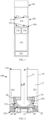
FIG. 1 is a schematic diagram of an electronic atomization device according to an embodiment; -
FIG. 2 is a schematic diagram of an atomizer inFIG. 1 according to an embodiment; -
FIG. 3 is a schematic diagram of an atomization assembly inFIG. 2 from an angle of view; -
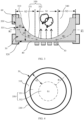
FIG. 4 is a top view of an atomization assembly according to an embodiment; -
FIG. 5 is a top view of an atomization assembly according to another embodiment; -
FIG. 6 is a schematic diagram of the atomization assembly inFIG. 5 from another angle of view; -
FIG. 7 is a schematic diagram of an atomization assembly according to another embodiment; -
FIG. 8 is a schematic diagram of an atomization assembly according to another embodiment; -
FIG. 9 is a schematic diagram of an atomization assembly according to another embodiment; and -
FIG. 10 is a schematic diagram of an atomization assembly according to another embodiment. - For ease of understanding of this application, this application is described in further detail below with reference to the accompanying drawings and specific implementations.
- This application provides an electronic atomization device, as shown in
FIG. 1 , including: anatomizer 100 configured to store a liquid substrate and atomize the liquid substrate to generate an aerosol; and apower supply assembly 200 configured to supply power to theatomizer 100. - In an optional embodiment, as shown in
FIG. 1 , thepower supply assembly 200 includes: a receivingcavity 270, arranged at an end along a length direction and configured to receive and accommodate at least part of theatomizer 100, and a firstelectrical contact 230, at least partially exposed on a surface of the receivingcavity 270 and configured to supply power to theatomizer 100 when the at least part of theatomizer 100 is received and accommodated in thepower supply assembly 200. - According to the preferred embodiment shown in
FIG. 1 , an end portion of theatomizer 100 opposite to thepower supply assembly 200 along the length direction is arranged with a secondelectrical contact 21, so that when the at least part of theatomizer 100 is received in the receivingcavity 270, the secondelectrical contact 21 forms conductivity by being in contact with and abutting against the firstelectrical contact 230. - A
seal element 260 is arranged inside thepower supply assembly 200, and at least part of an internal space of thepower supply assembly 200 is separated through theseal element 260 to form the receivingcavity 270. In the preferred embodiment shown inFIG. 1 , theseal element 260 is constructed to extend along a cross section direction of thepower supply assembly 200, and is preferably prepared by a flexible material, to prevent the liquid substrate seeping from theatomizer 100 to the receivingcavity 270 from flowing to components such as acontroller 220 and asensor 250 inside thepower supply assembly 200. - In the preferred embodiment shown in
FIG. 1 , thepower supply assembly 200 further includes: abattery core 210, located at another end away from the receivingcavity 270 along the length direction, and configured to supply power; and acontroller 220, arranged between thebattery core 210 and the receivingcavity 270, where thecontroller 220 operably guides a current between thebattery core 210 and the firstelectrical contact 230. - During use, the
power supply assembly 200 includes asensor 250, configured to sense an inhalation flow generated by theatomizer 100 during inhalation, so that thecontroller 220 controls thebattery core 210 to output the current to theatomizer 100 according to a detection signal of thesensor 250. - Further, in the preferred embodiment shown in
FIG. 1 , a charginginterface 240 is arranged on another end of thepower supply assembly 200 away from the receivingcavity 270, and is configured to supply power to thebattery core 210. - The embodiment in
FIG. 2 shows a schematic structural diagram of theatomizer 100 inFIG. 1 according to an embodiment. Theatomizer 100 includes:
amain housing 10. According toFIG. 2 , themain housing 10 is roughly in a longitudinal cylindrical shape, and certainly, its interior is hollow for necessary functional components for storing and atomizing the liquid substrate. Themain housing 10 has anear end 110 and afar end 120 opposite to each other along the length direction. According to the requirements of common use, thenear end 110 is configured as an end for the user to inhale the aerosol, and a suction nozzle A for the user to inhale is arranged on thenear end 110; and thefar end 120 is configured to as an end for combining thepower supply assembly 200. - Further, as shown in
FIG. 2 , themain housing 10 is internally arranged with aliquid storage cavity 12 for storing the liquid substrate, and an atomization assembly for absorbing the liquid substrate from theliquid storage cavity 12, and heating and atomizing the liquid substrate. In the schematic diagram shown inFIG. 2 , avapor conveying tube 11 is arranged along an axial direction in themain housing 10, and theliquid storage cavity 12 configured to store the liquid substrate is formed in a space between thevapor conveying tube 11 and an inner wall of themain housing 10. A first end of thenear end 110 opposite to thevapor conveying tube 11 is in communication with the suction nozzle A, so that the generated aerosol is conveyed to the suction nozzle A for inhalation. - Further, in some optional embodiments, the
vapor conveying tube 11 and themain housing 10 are integrally molded by using moldable materials, so that theliquid storage cavity 12 formed after preparation is open toward thefar end 120. - Further, as shown in
FIG. 2 andFIG. 3 , theatomizer 100 further includes the atomization assembly, configured to atomize at least part of the liquid substrate to generate the aerosol. Specifically, the atomization assembly includes a liquid guide element, such as aporous body 30 inFIG. 2 andFIG. 3 ; and aheating element 50, configured to heat and atomize the liquid substrate absorbed by theporous body 30. In addition, inFIG. 2 , theatomizer 100 further includes asupport element 20, arranged at thefar end 120 to provide support to the atomization assembly, so that the atomization assembly is stably assembled and maintained in themain housing 10. - In some embodiments, the
porous body 30 may be made of a rigid capillary element such as a porous ceramic, a porous glass ceramic, or porous glass. Alternatively, in some other embodiments, theporous body 30 includes a capillary element with an internal capillary channel that can absorb and convey the liquid substrate. - For a shape and a construction of the
porous body 30, as shown inFIG. 3 and FIG. 4 , theporous body 30 is in a cup-like shape or the like as a whole. In addition, in arrangement, an axial direction of theporous body 30 is substantially arranged coaxial with or arranged in parallel to a central axis of themain housing 10. - Specifically, the
porous body 30 includes:
asurface 310 and asurface 320 opposite to each other along the axial direction, and asurface 330 between thesurface 310 and thesurface 320. In the embodiments shown inFIG. 2 andFIG. 3 , thesurface 310 is toward or adjacent to thenear end 110, and thesurface 320 is toward or close to thefar end 120. Thesurface 310 and thesurface 320 are parallel to each other, and are both flat. Thesurface 330 is an outer surface of theporous body 30, and is perpendicular to thesurface 310 and thesurface 320. Thesurface 330 is a peripheral surface of theporous body 30, and is substantially an annular shape that surrounds along a circumferential direction of theporous body 30 or surrounds theporous body 30. - Alternatively, in another variant embodiment, the
surface 330 is obliquely arranged, to be at an acute angle or an obtuse angle or a non-zero angle with thesurface 320. For example, in another variant embodiment shown inFIG. 8 , an angle between asurface 330c and acoating layer 40c is obliquely arranged to be an acute angle. - Further, as shown in
FIG. 3 , thesurface 330 and thesurface 320 are intersected. Thesurface 350 and thesurface 320 are not intersected. - During implementation, the
surface 310 is helpful for a stable maintenance of a sealingelement 60 abutting against asurface 30 during assembly. Alternatively, in some other variant embodiments, theporous body 30 does not have thesurface 310, for example, the atomization assembly of the variant embodiment shown inFIG. 8 to FIG. 10 . Correspondingly, it is convenient for the sealingelement 60 to stably combine with theporous body 30 by abutting against acoating layer 40. - Further, as shown in
FIG. 2 andFIG. 3 , during use after assembly, part of thesurface 330 of theporous body 30 is surrounded by the sealingelement 60. In addition, thesurface 330 of theporous body 30 also has an exposedpart 331 that is not surrounded by the sealingelement 60. During implementation, the exposedpart 331 is configured to be a liquid absorbing surface that is directly exposed in theliquid storage cavity 12 to absorb the liquid substrate. Alternatively, in other variant embodiments, the exposedpart 331 that is not surrounded by the sealingelement 60 is in indirect communication with theliquid storage cavity 12 via a liquid channel to absorb the liquid substrate. - Further, as shown in
FIG. 2 andFIG. 3 , thesurface 320 of theporous body 30 is substantially completely covered and coated by thecoating layer 40. Specifically, in some embodiments, thecoating layer 40 includes a thin film of glaze, a dense ceramic, an inorganic oxide (such as zirconia, alumina, boron oxide, or titanium oxide), an inorganic nitride (such as silicon nitride, aluminum nitride, or calcium nitride), a surface-insulated metal, or the like. Complete coating of thesurface 320 by thecoating layer 40 substantially prevents the liquid substrate and the aerosol from seeping or overflowing from, or leaving thesurface 320. - Further, as shown in
FIG. 2 andFIG. 3 , the atomization assembly further includes:
theheating element 50, combined on a surface of thecoating layer 40. Further, as shown inFIG. 2 andFIG. 3 , theheating element 50 is substantially arranged in a central region near the surface of thecoating layer 40. During implementation, theheating element 50 is not in contact with a surface of theporous body 30. - The
surface 350 is close to, or toward, or adjacent to thenear end 110, and is a concave oblique surface. Therefore, thesurface 350 defines aconcave cavity 340 that is close to, or toward, or adjacent to thenear end 110. During use, theconcave cavity 340 is configured to be an atomization chamber for releasing the aerosol. - As shown in
FIG. 3 and FIG. 4 , when theheating element 50 is arranged, theporous body 30 includes: - a porous part S1, being roughly or substantially a part opposite to an arrangement region of the
heating element 50 along the axial direction, where the porous part S1 is mainly configured to receive heat of theheating element 50 to atomize an atomization region part of the liquid substrate; and - a porous part S2, being a part that avoids the arrangement region of the
heating element 50 along the axial direction, where the porous part S2 in the figure is defined between the porous part S1 and thesurface 330. During use, the porous part S2 is a part mainly configured to absorb and store the liquid substrate, and convey the liquid substrate to the porous part S1. For example, as shown inFIG. 2 andFIG. 3 , the liquid substrate is absorbed by the exposedpart 331 of thesurface 330 into the porous part S2 and is conveyed along an arrow R1 to the porous part S1 to be atomized as the aerosol. - Specifically, as shown in
FIG. 3 , thesurface 350 has afirst region part 351 that avoids theheating element 50 along the axial direction, and asecond region part 352 opposite to theheating element 50 or covering theheating element 50. The porous part S1 is a part defined between thesecond region part 352 of thesurface 350 and thesecond surface 320. - Further, as shown in
FIG. 3 , a surface of the porous part S1 away from thesurface 320 is exposed. Therefore, during use, the surface of the porous part S1 away from thesurface 320 is an aerosol release surface for the generated aerosol to overflow. - Further, as shown in
FIG. 2 , after assembly, anatomization chamber 340 of theporous body 30 is in airflow communication with thevapor conveying tube 11, so that thevapor conveying tube 11 may be used to convey the aerosol to the suction nozzle A for user inhalation. In addition, after assembly, theatomization chamber 340 is separated from or sealed with theliquid storage cavity 12 via acomponent 70. - In the embodiment shown in
FIG. 2 , the secondelectrical contact 21 of theatomizer 100 penetrates into theatomizer 100 from thefar end 120, and directly or indirectly forms conductivity with theheating element 50 by directly abutting against theheating element 50, wire welding, conductive spring piece, or other manners. - In some embodiments, a cross section of the
porous body 30 may be constructed as a circle, as shown inFIG. 4 . Alternatively, in another variant embodiment shown inFIG. 5 , the cross section of theporous body 30 may be constructed as a shape of a square or rectangle. Alternatively, in other variant embodiments, the cross section of theporous body 30 may be more of a regular or irregular shape, such as a polygon. - Based on functional requirements for heating and atomizing, the
heating element 50 usually uses a resistive metal material or a metal alloy material with appropriate impedance. For example, an appropriate metal or alloy material includes at least one of nickel, cobalt, zirconium, titanium, nickel alloy, cobalt alloy, zirconium alloy, titanium alloy, nickel chromium alloy, nickel iron alloy, iron chromium alloy, titanium alloy, iron manganese aluminum based alloy, or stainless steel. - In preparation, the
heating element 50 may be in a form of a printed or a deposited resistance heating trajectory. In some embodiments, theheating element 50 may be a patterned resistance heating trajectory. In some other embodiments, theheating element 50 is planar. - In some embodiments, after the
heating element 50 is formed through cutting or etching by a sheet-like metal substrate, theheating element 50 is attached to theporous body 30 having thecoating layer 40. Alternatively, in some other embodiments, theheating element 50 is formed by mixing a raw material (such as metal powder of nickel chromium alloy) with an amount of sintering aids to form a mixed slurry, then brushing the mixed slurry on the surface of thecoating layer 40 according to the shape described in the above embodiments, and then firing. For example,FIG. 6 shows a schematic diagram of aheating element 50a in an embodiment. In this embodiment, theheating element 50a is obtained through sintering by printing acoating layer 40a. - Alternatively, in some other variant embodiments, the
heating element 50/50a is an inductive heating element penetrable by a changing magnetic field to generate heat. Correspondingly, a magnetic field generator, such as an induction coil, that is configured to generate an alternating magnetic field, may be further arranged in theatomizer 100. - Alternatively, in some other variant embodiments, the
heating element 50/50a is not exposed on the surface of thecoating layer 40/40a, but embedded or buried in thecoating layer 40/40a. - Further, as shown in
FIG. 3 , a distance d1 between thesecond region part 352 of thesurface 350 of theporous body 30 and thesurface 320 is constructed to gradually decrease inward along a radial direction. - In addition, in a preferred embodiment, a shortest distance between the
second region part 352 and thesurface 320 is greater than 0.01 mm. That is, a minimum value of the distance d1 is 0.01 mm. - In a preferred embodiment, the
second region part 352 is at the porous part S1 that is used as an atomization region, and the distance d1 between thesecond region part 352 and thesurface 320 is preferably ranges from 0.01 mm to 0.5 mm. - In some preferred embodiments, a porosity of the
porous body 30 ranges from 40% to 70%. In addition, a pore dimension of a capillary pore in theporous body 30 ranges from 10 µm to 100 µm. - In some embodiments, a thickness of the
coating layer 40 ranges approximately from 0.05 mm to 0.2 mm. - In addition, a distance d2 between the
surface 350 of theporous body 30 and thesurface 330 is constructed to gradually increase along a direction close to thesurface 320. - In the embodiment shown in
FIG. 3 , thesurface 350 is constructed to be spherical curved. - In some preferred embodiments, in an overall dimension of the
porous body 30, a length of theporous body 30 along the axial direction ranges approximately from 3 mm to 6 mm. An outer diameter of theporous body 30 along the radial direction ranges from 8 mm to 12 mm. - In some embodiments, a projection area of the porous part S1 on the
second surface 320/320a in the foregoing embodiments ranges approximately from 10% to 50% of an area of thesecond surface 320/320a. - In some embodiments, the
porous body 30/30a combined with thecoating layer 40/40a is formed through sintering by sequentially printing their raw materials layer by layer by using a 3D printing technology. Alternatively, in some other embodiments, theporous body 30/30a combined with thecoating layer 40/40a is formed through sintering by sequentially injecting and hot pressing their raw materials into a mold. Alternatively, in some other embodiments, thecoating layer 40/40a is formed on theporous body 30/30a through spraying, vapor deposition, brushing, printing, and transfer printing. - Further,
FIG. 7 shows a schematic diagram of the atomization assembly in another optional embodiment. Aporous body 30b in the atomization assembly in this embodiment includes: - a
surface 311b and asurface 320b opposite to each other along the axial direction, where thesurface 320b is covered by acoating layer 40b, to prevent the liquid substrate or the aerosol from seeping or overflowing from thesurface 320b, and thesurface 311b and thesurface 320b are flat surfaces; - a
surface 330b, being an outer surface that surrounds theporous body 30b, where after assembly or during use, at least part of thesurface 330b is a liquid absorbing surface for absorbing the liquid substrate; structurally, thesurface 330b extends from thesurface 311b to asurface 312b; and substantially, thesurface 330b is perpendicular to thesurface 311b and thesurface 312b; - a
fourth surface 313b, being located at a side away from thesurface 320, and being a flat surface parallel to thesurface 320b; in dimension, thesurface 313b coincides with a projection of aheating element 50b; and therefore, during use, a part between thesurface 313b and theheating element 50b defines theporous body 30b as the porous part S1 of the atomization region; and - a
surface 312b, extending from thesurface 311b to thesurface 313b, where thesurface 312b is obliquely arranged, that is, thesurface 312b is at an angle with thesurface 311b and theangle 313b. - During use, a
concave cavity 340b jointly defined by thesurface 312b and thesurface 313b serves as the atomization chamber for releasing the aerosol. A distance between thesurface 313b and thesurface 320b preferably ranges from 0.01 mm to 0.5 mm. - It should be noted that, the specification of this application and the accompanying drawings thereof illustrate preferred embodiments of this application, but are not limited to the embodiments described in this specification, furthermore, a person of ordinary skill in the art may make improvements or modifications according to the foregoing description, and all the improvements and modifications shall fall within the protection scope of the attached claims of this application.
Claims (25)
- An atomizer, comprising:a liquid storage cavity, configured to store a liquid substrate; anda porous body, comprising a first surface, a second surface, and a third surface, whereinthe first surface is constructed to be in fluid communication with the liquid storage cavity, for at least part of the liquid substrate to enter the porous body via the first surface;a coating layer that covers the second surface is formed on the second surface; the coating layer is combined with a heating element to heat the at least part of the liquid substrate in the porous body to generate an aerosol; andthe third surface is an exposed surface, for releasing the aerosol.
- The atomizer according to claim 1, wherein the porous body comprises a porous ceramic.
- The atomizer according to claim 1 or 2, wherein the coating layer comprises a dense ceramic, glaze, a metal or an inorganic oxide or an inorganic nitride.
- The atomizer according to claim 1 or 2, wherein the second surface is a flat surface.
- The atomizer according to claim 1 or 2, wherein the heating element is a heating element printed or deposited on the coating layer.
- The atomizer according to claim 1 or 2, wherein the heating element is a planar heating element.
- The atomizer according to claim 1 or 2, wherein the heating element comprises a resistance heating trajectory formed on the coating layer.
- The atomizer according to claim 1 or 2, wherein the heating element is an inductive heating element penetrable by a changing magnetic field to generate heat.
- The atomizer according to claim 1 or 2, wherein the third surface is arranged away from the coating layer.
- The atomizer according to claim 9, wherein a projection of the third surface on a surface of the coating layer covers the heating element.
- The atomizer according to claim 9, wherein a distance between the third surface and the first surface gradually decreases along a direction of the third surface away from the coating layer.
- The atomizer according to claim 1 or 2, wherein the first surface is constructed to extend along a circumferential direction of the porous body.
- The atomizer according to claim 1 or 2, wherein there is an angle between the first surface and the second surface.
- The atomizer according to claim 1, wherein the first surface at least partially extends between the second surface and the third surface.
- The atomizer according to claim 1 or 2, wherein the third surface is constructed to be obliquely arranged along a direction close to the second surface.
- The atomizer according to claim 1 or 2, wherein the third surface is substantially parallel to the second surface.
- The atomizer according to claim 1 or 2, wherein a distance between the third surface along an axial direction of the porous body and the second surface ranges from 0.01 mm to 0.5 mm.
- The atomizer according to claim 1 or 2, wherein a minimum distance between the third surface along an axial direction of the porous body and the second surface is 0.01 mm.
- The atomizer according to claim 1 or 2, wherein the third surface is at least partially constructed as a curved surface.
- The atomizer according to claim 1 or 2, wherein the third surface is at least partially defined with a concave cavity.
- The atomizer according to claim 20, wherein the concave cavity is constructed to accommodate at least part of an atomization chamber of the aerosol.
- The atomizer according to claim 20, wherein the concave cavity is separated from the liquid storage cavity.
- The atomizer according to claim 1 or 2, wherein the coating layer is configured to prevent the liquid substrate or the aerosol from leaving the second surface.
- An electronic atomization device, comprising an atomizer configured to atomize a liquid substrate to generate an aerosol and a power supply assembly configured to supply power to the atomizer, wherein the atomizer comprises the atomizer according to any one of claims 1 to 23.
- An atomization assembly for an atomizer, comprising:a porous body, comprising a first surface, a second surface, and a third surface, wherein the second surface and the third surface are arranged oppositely along an axial direction of the porous body, and the first surface is used to receive a liquid substrate, for the liquid substrate to enter the porous body;a coating layer, covering the second surface; anda heating element, combined on the coating layer, whereinthe third surface is an exposed surface, for releasing an aerosol.
Applications Claiming Priority (2)
| Application Number | Priority Date | Filing Date | Title |
|---|---|---|---|
| CN202111345696.8A CN116114919A (en) | 2021-11-15 | 2021-11-15 | Atomizer, electronic atomization device and atomization assembly for atomizer |
| PCT/CN2022/131773 WO2023083358A1 (en) | 2021-11-15 | 2022-11-14 | Atomizer, electronic atomization device, and atomization assembly for atomizer |
Publications (2)
| Publication Number | Publication Date |
|---|---|
| EP4434368A1 true EP4434368A1 (en) | 2024-09-25 |
| EP4434368A4 EP4434368A4 (en) | 2025-03-05 |
Family
ID=86310392
Family Applications (1)
| Application Number | Title | Priority Date | Filing Date |
|---|---|---|---|
| EP22892151.6A Pending EP4434368A4 (en) | 2021-11-15 | 2022-11-14 | ATOMIZER, ELECTRONIC ATOMIZING DEVICE AND ATOMIZING ASSEMBLY FOR ATOMIZER |
Country Status (4)
| Country | Link |
|---|---|
| US (1) | US20250009025A1 (en) |
| EP (1) | EP4434368A4 (en) |
| CN (1) | CN116114919A (en) |
| WO (1) | WO2023083358A1 (en) |
Family Cites Families (14)
| Publication number | Priority date | Publication date | Assignee | Title |
|---|---|---|---|---|
| US11117068B2 (en) * | 2014-10-20 | 2021-09-14 | Numerical Designs, Inc. | Microfluidic-based apparatus and method for vaporization of liquids |
| US10334882B2 (en) * | 2016-04-13 | 2019-07-02 | Md&C Creative Masion Sa | Electronic cigarette |
| CN108185536B (en) * | 2018-02-13 | 2020-01-21 | 深圳麦克韦尔科技有限公司 | Electronic cigarette and its atomizer |
| US10932490B2 (en) * | 2018-05-16 | 2021-03-02 | Rai Strategic Holdings, Inc. | Atomizer and aerosol delivery device |
| CN109527657A (en) * | 2018-12-21 | 2019-03-29 | 深圳市合元科技有限公司 | The preparation method and electronic smoke atomizer of atomizing component |
| CN109674094A (en) * | 2019-01-26 | 2019-04-26 | 深圳市合元科技有限公司 | Electronic smoke atomizer and electronic cigarette, atomizing component preparation method |
| CN110074464B (en) * | 2019-05-15 | 2024-04-16 | 深圳市你我网络科技有限公司 | Atomizer and electronic cigarette |
| CN112006329A (en) * | 2019-05-28 | 2020-12-01 | 深圳市合元科技有限公司 | Atomizing core, atomizer and aerosol generating device |
| CN110419779B (en) * | 2019-07-15 | 2024-08-06 | 深圳市合元科技有限公司 | Electronic cigarette atomizer, electronic cigarette and preparation method of atomization component |
| CN210726705U (en) * | 2019-08-19 | 2020-06-12 | 常州市派腾电子技术服务有限公司 | Atomization assembly, atomizer and aerosol generating device |
| CN213344341U (en) * | 2020-05-14 | 2021-06-04 | 深圳市合元科技有限公司 | Electronic Cigarettes and Electronic Cigarettes |
| CN213587424U (en) * | 2020-09-08 | 2021-07-02 | 深圳市合元科技有限公司 | Vape Vaporizers and Electronic Cigarettes |
| CN112826142B (en) * | 2021-02-09 | 2025-04-22 | 深圳市华诚达精密工业有限公司 | Atomizer core, atomizer device and aerosol generating device |
| CN115670029A (en) * | 2021-07-24 | 2023-02-03 | 比亚迪精密制造有限公司 | Electronic cigarette component, preparation method of atomizing core and electronic cigarette |
-
2021
- 2021-11-15 CN CN202111345696.8A patent/CN116114919A/en active Pending
-
2022
- 2022-11-14 WO PCT/CN2022/131773 patent/WO2023083358A1/en not_active Ceased
- 2022-11-14 EP EP22892151.6A patent/EP4434368A4/en active Pending
- 2022-11-14 US US18/705,564 patent/US20250009025A1/en active Pending
Also Published As
| Publication number | Publication date |
|---|---|
| CN116114919A (en) | 2023-05-16 |
| EP4434368A4 (en) | 2025-03-05 |
| US20250009025A1 (en) | 2025-01-09 |
| WO2023083358A1 (en) | 2023-05-19 |
Similar Documents
| Publication | Publication Date | Title |
|---|---|---|
| CN110662437B (en) | Vaporizing unit of personal vaporizing device | |
| AU2016253576B2 (en) | An aerosol generating device with a capillary interface | |
| AU2012347294B2 (en) | An aerosol generating device with air flow nozzles | |
| KR20180121666A (en) | Vaporizer for electronic aerosol providing system and electronic aerosol providing system | |
| CN108150989A (en) | Heating element, vaporization device, method for vaporizing fluid sprayed by spray head | |
| CN217609576U (en) | Aerosol generator and atomising unit for liquid substrates | |
| CN216931907U (en) | Heating assembly, atomizer and electronic atomization device | |
| EP4289293A1 (en) | Atomizer, electronic atomization device and atomization assembly | |
| US12446621B2 (en) | Evaporator tank unit for an inhaler, preferably an electronic cigarette product, electronic cigarette product and wick structure | |
| EP4434368A1 (en) | Atomizer, electronic atomization device, and atomization assembly for atomizer | |
| CN216019092U (en) | Heating tube and aerosol generating device | |
| CN114190608A (en) | Resistance heater for aerosol-generating device and aerosol-generating device | |
| CN218978034U (en) | Atomizer, electronic atomization device and atomization assembly for electronic atomization device | |
| CN112641134A (en) | Heating tube, method for manufacturing the same, and aerosol generating apparatus | |
| CN219982154U (en) | Atomizer, electronic atomization device and atomization assembly for atomizer | |
| CN220274946U (en) | Atomizers and electronic atomization devices | |
| CN218682018U (en) | Atomizer, electronic atomization device and atomization assembly | |
| CN116406825B (en) | Porous body, atomizer, and electronic atomizing device | |
| EP4445758A1 (en) | Porous body, atomizer and electronic atomization device | |
| CN224192942U (en) | Electronic atomizing device and porous element for electronic atomizing device | |
| CN118303668A (en) | Atomizer, electronic atomization device, atomization assembly and preparation method | |
| CN118575989A (en) | Atomizer, electronic atomizer device and atomizer assembly for atomizer | |
| CN116941823A (en) | Atomizer, electronic atomization device and atomization assembly for atomizer | |
| CN117617558A (en) | Atomizers, electronic atomization devices and atomization components for atomizers | |
| CN115606855A (en) | Heater for aerosol generating device and aerosol generating device |
Legal Events
| Date | Code | Title | Description |
|---|---|---|---|
| STAA | Information on the status of an ep patent application or granted ep patent |
Free format text: STATUS: THE INTERNATIONAL PUBLICATION HAS BEEN MADE |
|
| PUAI | Public reference made under article 153(3) epc to a published international application that has entered the european phase |
Free format text: ORIGINAL CODE: 0009012 |
|
| STAA | Information on the status of an ep patent application or granted ep patent |
Free format text: STATUS: REQUEST FOR EXAMINATION WAS MADE |
|
| 17P | Request for examination filed |
Effective date: 20240327 |
|
| AK | Designated contracting states |
Kind code of ref document: A1 Designated state(s): AL AT BE BG CH CY CZ DE DK EE ES FI FR GB GR HR HU IE IS IT LI LT LU LV MC ME MK MT NL NO PL PT RO RS SE SI SK SM TR |
|
| STAA | Information on the status of an ep patent application or granted ep patent |
Free format text: STATUS: EXAMINATION IS IN PROGRESS |
|
| DAV | Request for validation of the european patent (deleted) | ||
| DAX | Request for extension of the european patent (deleted) | ||
| A4 | Supplementary search report drawn up and despatched |
Effective date: 20250130 |
|
| RIC1 | Information provided on ipc code assigned before grant |
Ipc: A24F 40/10 20200101ALN20250124BHEP Ipc: A24F 40/44 20200101ALI20250124BHEP Ipc: A24F 40/46 20200101ALI20250124BHEP Ipc: A24F 40/48 20200101AFI20250124BHEP |
|
| 17Q | First examination report despatched |
Effective date: 20250211 |