EP4434321A1 - Electrically driven and controlled drive box for corn headers - Google Patents
Electrically driven and controlled drive box for corn headers Download PDFInfo
- Publication number
- EP4434321A1 EP4434321A1 EP24165425.0A EP24165425A EP4434321A1 EP 4434321 A1 EP4434321 A1 EP 4434321A1 EP 24165425 A EP24165425 A EP 24165425A EP 4434321 A1 EP4434321 A1 EP 4434321A1
- Authority
- EP
- European Patent Office
- Prior art keywords
- box
- headers
- control
- transmission box
- corn
- Prior art date
- Legal status (The legal status is an assumption and is not a legal conclusion. Google has not performed a legal analysis and makes no representation as to the accuracy of the status listed.)
- Pending
Links
Images


Classifications
-
- A—HUMAN NECESSITIES
- A01—AGRICULTURE; FORESTRY; ANIMAL HUSBANDRY; HUNTING; TRAPPING; FISHING
- A01D—HARVESTING; MOWING
- A01D45/00—Harvesting of standing crops
- A01D45/02—Harvesting of standing crops of maize, i.e. kernel harvesting
- A01D45/026—Hand implements
-
- A—HUMAN NECESSITIES
- A01—AGRICULTURE; FORESTRY; ANIMAL HUSBANDRY; HUNTING; TRAPPING; FISHING
- A01D—HARVESTING; MOWING
- A01D45/00—Harvesting of standing crops
- A01D45/02—Harvesting of standing crops of maize, i.e. kernel harvesting
- A01D45/021—Cornheaders
- A01D45/023—Gathering chains of belts
-
- A—HUMAN NECESSITIES
- A01—AGRICULTURE; FORESTRY; ANIMAL HUSBANDRY; HUNTING; TRAPPING; FISHING
- A01D—HARVESTING; MOWING
- A01D45/00—Harvesting of standing crops
- A01D45/02—Harvesting of standing crops of maize, i.e. kernel harvesting
- A01D45/021—Cornheaders
-
- A—HUMAN NECESSITIES
- A01—AGRICULTURE; FORESTRY; ANIMAL HUSBANDRY; HUNTING; TRAPPING; FISHING
- A01D—HARVESTING; MOWING
- A01D69/00—Driving mechanisms or parts thereof for harvesters or mowers
- A01D69/02—Driving mechanisms or parts thereof for harvesters or mowers electric
-
- A—HUMAN NECESSITIES
- A01—AGRICULTURE; FORESTRY; ANIMAL HUSBANDRY; HUNTING; TRAPPING; FISHING
- A01D—HARVESTING; MOWING
- A01D69/00—Driving mechanisms or parts thereof for harvesters or mowers
- A01D69/06—Gearings
Definitions
- the present invention relates to a novel electrically driven transmission box, mounted in correspondence of each row of the head itself, replacing the conventional control resources used to date that are mechanically driven.
- the transmission boxes for corn headers that are known today are used one per furrow, and they are distinguished because they receive control through a power transmission shaft, at a pre-established speed and power, their function being to multiply and/or reduce to drive all the other assemblies that make up the header, such as the gears, chains, and toe caps, which are basically in charge of channeling the plant, collecting it, separating the useful parts, and arranging them for subsequent phases carried out by the harvesting machine.
- the optimal harvesting speed (relationship between linear forward speed / box rpm) is a key factor in reducing loss levels.
- the speed limit is conditioned by the state of the crop among other factors, so with the current system (mechanical control) it is not possible to adjust the optimal harvesting speed dynamically due to the variation in the state of the crop in different areas.
- the rpm of the boxes is linked to the linear forward speed of the machine. Therefore, for different feed rates the sprocket configurations must be changed manually, and in this way synchronize both speeds. This has three problems, the first is that the speed relationships are limited, the second is that they demand that the user must have a large number of combinations, and the third is that they must perform this task manually.
- One of the main objectives of this invention is to be an horr-garde option in the face of technological advances that the agricultural industry is making globally in machinery, mechanical assemblies, among others, which are mutating to work electrically from simple drives, to integrally in agricultural machines that work remotely and autonomously.
- This electrification requires transmissions with these characteristics to also work electrically, in order to be synchronized and linked to the other components and systems of the machine. As well as achieving performances close to 99% efficiency.
- One of the main advantages of using an electrically driven gearbox is to offer a direct relationship with the advance of the combine harvester individually, that is, furrow by furrow, which allows that as the forward speed increases, the synchronize automatically the working speed of the transmissions, with the corresponding speeds for such advancement, this being a virtue that the mechanical version cannot perform in such a way.
- this invention contemplates the use of a torque limiter (which may be arranged both internally and externally), which is a safety element of the device since in the event of excessive torque/tension peaks that can force the box due to variations in the terrain to be worked on or jamming of some kind that usually happens.
- This release acts by decoupling the power transmission link to the box, or by limiting the intensity of electric current and/or through voltage, which could eliminate the use of conventional limiters.
- the transmission box to which the present invention refers is distinguished because it includes an electric motor that controls a set of axles and central gears through which they distribute the rotation to the axles of the lifting chains of each furrow, as well as the axles that command the rolls of the same groove.
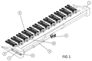
- Figure 1 is a graphic representation of what the control for the operation of a corn header currently looks like.
- chassis (1) which has a platform that links it to the combine.
- the transmission boxes (3) that control the collection system are mounted on said chassis (1).
- the number of boxes (3) or furrows depends on the header configuration and determines the working width, together with the distance between furrows.
- the mechanical drive of the boxes (3) is carried out through a kinematic control system composed of the control bar (4) coupled to the combine's own power take-off (2) on the one hand, and to the gear wheels (5) and (6), the lateral control chain (7), and the box control bar (8).
- the transmission box for corn headers of the present invention is distinguished because it is driven by an electric motor (9) that projects out of the box, on one of its lateral sides, which gives control to the entire assembly of axle and central gears that distribute the rotation towards the axles (11) of the lifting chains, the axes that control the rollers (12), and may or may not have the cutting blade command axis (13).
- the invented transmission box has the shaft of the electric motor (9) arranged to rotate counterclockwise, as indicated by the arrow (F1) with respect to a horizontal axis, in which case the aforementioned control shafts (11) for the lifting chains rotate as indicated by the arrows (F2) and (F3) regarding their respective vertical axes.
- central axis (17) (indicated in figure 6 ) produces an anti-clockwise rotation (F4), while the roles (12) will have respective turns (F5) y (F6).
Landscapes
- Life Sciences & Earth Sciences (AREA)
- Environmental Sciences (AREA)
- Harvester Elements (AREA)
- Harvesting Machines For Root Crops (AREA)
- Agricultural Machines (AREA)
Abstract
Description
- The present invention, for which a patent is requested, has as its main object an ELECTRICALLY DRIVEN AND CONTROLLED TRANSMISSION BOX FOR CORN HEADERS, specially designed to be applied in harvesting machines of the type that have built-in headers to guide and channel the plant being harvested, to then uproot the crop from its non-useful remains.
- More specifically, the present invention relates to a novel electrically driven transmission box, mounted in correspondence of each row of the head itself, replacing the conventional control resources used to date that are mechanically driven.
- As is known, the transmission boxes for corn headers that are known today are used one per furrow, and they are distinguished because they receive control through a power transmission shaft, at a pre-established speed and power, their function being to multiply and/or reduce to drive all the other assemblies that make up the header, such as the gears, chains, and toe caps, which are basically in charge of channeling the plant, collecting it, separating the useful parts, and arranging them for subsequent phases carried out by the harvesting machine.
- In this sense, it is highlighted that with the transmission box referred to in this invention, an avant-garde option is shown that takes into account the technological advances that the agricultural industry is making globally in machinery. Mechanical assemblies can be seen, which are mutating to work electrically, both in simple drive tools, to comprehensive agricultural machines that work remotely and autonomously.
- This operating principle leads us to require that transmissions with these characteristics also work electrically, in order to be synchronized and linked to the other components and systems of the machine, as well as achieving performances close to 99% efficiency.
- One of the main advantages is to offer a direct relationship with the advance of the combine individually, that is, furrow by furrow, which allows it to be synchronized as the forward speed increases automatically the working speed of the transmissions, with the corresponding speeds for such advancement, this being a virtue that the mechanical version cannot perform in such a way. It should also be noted that when working on plateaus and/or when making curves while harvesting, with this invention it can be operated individually and adjust in an autonomous mode each box to increase speeds.
- It is an invention that defines a new combination of means designed to achieve a superior result, being unpredictable and surprising even for an expert in the specialty. Consequently, in addition to being new, its constructive and functional conception shows a clear inventive activity, so that it meets the conditions required by the Law to be considered a patent for an invention.
- As is known, currently these gearboxes are mechanically driven, which means that they are made up of a high number of components that, when working together mechanically, the final efficiency of the machine is not high. Since there are losses due to heat generation due to rubbing and friction, and this happens in all the furrows, which on average according to the market is 20 rows per machine. Furthermore, as it does not contain electronic components and has very little internal space it is not feasible to incorporate the monitoring and control systems that the same combine already has.
- The optimal harvesting speed (relationship between linear forward speed / box rpm) is a key factor in reducing loss levels.
- The speed limit is conditioned by the state of the crop among other factors, so with the current system (mechanical control) it is not possible to adjust the optimal harvesting speed dynamically due to the variation in the state of the crop in different areas.
- In the same way, but to a lesser extent, as mentioned above, it happens that, in high working width headers, when making turns at the headers of the batches, the boxes all continue working at the same rpm as each other, which produces variations in the quality of the plant harvest in the different work grooves.
- The rpm of the boxes is linked to the linear forward speed of the machine. Therefore, for different feed rates the sprocket configurations must be changed manually, and in this way synchronize both speeds. This has three problems, the first is that the speed relationships are limited, the second is that they demand that the user must have a large number of combinations, and the third is that they must perform this task manually.
- One of the main objectives of this invention is to be an avant-garde option in the face of technological advances that the agricultural industry is making globally in machinery, mechanical assemblies, among others, which are mutating to work electrically from simple drives, to integrally in agricultural machines that work remotely and autonomously. This electrification requires transmissions with these characteristics to also work electrically, in order to be synchronized and linked to the other components and systems of the machine. As well as achieving performances close to 99% efficiency.
- One of the main advantages of using an electrically driven gearbox is to offer a direct relationship with the advance of the combine harvester individually, that is, furrow by furrow, which allows that as the forward speed increases, the synchronize automatically the working speed of the transmissions, with the corresponding speeds for such advancement, this being a virtue that the mechanical version cannot perform in such a way.
- It should also be noted that when working on plateaus and/or in moments of making curves while harvesting, with this invention you can operate in individually and autonomously adjust the speeds in each box on demand for the harvesting speed. As is known, in these cases the speed at one end of the head will be greater than in the middle where there will be another lower speed, and at the opposite end an even lower speed, due to the radii described in the working path.
- It can be said that the self-generation of energy, the reduction of emissions, as well as the consumption of energy sources is and will be increasingly requested, as well as robotization is this type of machinery, which will require a electric drive box as described in this invention.
- Furthermore, this invention contemplates the use of a torque limiter (which may be arranged both internally and externally), which is a safety element of the device since in the event of excessive torque/tension peaks that can force the box due to variations in the terrain to be worked on or jamming of some kind that usually happens. This release acts by decoupling the power transmission link to the box, or by limiting the intensity of electric current and/or through voltage, which could eliminate the use of conventional limiters.
- In this sense, it is highlighted that the difference with respect to the mechanical lock in all boxes is beneficial, since a part that is composed of multiple mechanical components that can be the cause of failure is eliminated, achieving in addition, that everyone works in the same way, to reduce costs, etc.
- It is also highlighted that, with the gearbox of this invention, when it is electrically driven, it allows it to be controlled, communicated, and maneuvered from the same monitor, interface, and electronics that the machines already have nowadays. Allowing everything to work with greater control, harmony, and linkage between the parties, also achieving full control over the system for its control and improvement in its operational service. Another advantage of the invention is the reduction of noise throughout the header, which improves perception and comfort for the machinist.
- The transmission box to which the present invention refers is distinguished because it includes an electric motor that controls a set of axles and central gears through which they distribute the rotation to the axles of the lifting chains of each furrow, as well as the axles that command the rolls of the same groove.
- The same shaft and central gears can be used as a control to control a cutting blade. It is clarified that both the distribution and internal configuration of all the aforementioned gears and the position of mounting of the electric drive motor, may vary by virtue of the design of the box, but the principle of operation and internal relationship is the same.
- No transmission box for corn headers known in the present day proposes, and does not even suggest, the constructive solution that arises from what is indicated in the preceding paragraphs, which is why it is a proposal that, in addition to being novel, has a clear inventive activity.
- To specify the advantages briefly mentioned, to which users and those skilled in the art will be able to add many more, and to facilitate the understanding of the constructive, constitutive, and functional characteristics of the invented transmission box, a preferred embodiment example is described below, which is illustrated schematically and without a determined scale, in the attached plates, with the express clarification that, precisely, since it is an example, it is not appropriate to assign a limiting or exclusive character to the scope of protection of the present invention, but rather it simply has a merely explanatory and illustrative intention of the basic conception on which it is based.
-
Figure 1 is a schematic perspective that shows the mechanical control currently used by transmission boxes in corn headers in general. -
Figure 2 is an exterior perspective view representing a groove of corn header that includes the transmission box of this invention. -
Figure 3 is also a perspective view of the same transmission box as in the previous figure, without the casing that closes it. -
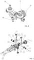
Figure 4 is also a perspective showing the combination of gears that make up the box of this invention. -
Figure 5 is an exploded perspective of the same combination of figure three gears. -
Figure 6 is an exploded perspective similar to the previous figure, observed from another side. - It is clarified that, in all figures, with the same reference numbers and letters, the same or equivalent parts or elements constituting the assembly correspond, according to the example chosen for the present explanation of the invented transmission box.
-
Figure 1 is a graphic representation of what the control for the operation of a corn header currently looks like. - It can be seen that it is arranged with a chassis (1) which has a platform that links it to the combine. The transmission boxes (3) that control the collection system are mounted on said chassis (1). The number of boxes (3) or furrows depends on the header configuration and determines the working width, together with the distance between furrows.
- The mechanical drive of the boxes (3) is carried out through a kinematic control system composed of the control bar (4) coupled to the combine's own power take-off (2) on the one hand, and to the gear wheels (5) and (6), the lateral control chain (7), and the box control bar (8).
- If we now look at
figures 2, 3 and4 , it is possible to see that the transmission box for corn headers of the present invention is distinguished because it is driven by an electric motor (9) that projects out of the box, on one of its lateral sides, which gives control to the entire assembly of axle and central gears that distribute the rotation towards the axles (11) of the lifting chains, the axes that control the rollers (12), and may or may not have the cutting blade command axis (13). - Both the distribution and internal configuration of all the gears and the mounting position of the electric motor (9) may vary due to the design of the box, but the construction and operating principle would be the same.
- If we now look at
figure 5 , we can see that, in this embodiment, the invented transmission box has the shaft of the electric motor (9) arranged to rotate counterclockwise, as indicated by the arrow (F1) with respect to a horizontal axis, in which case the aforementioned control shafts (11) for the lifting chains rotate as indicated by the arrows (F2) and (F3) regarding their respective vertical axes. - Likewise, the central axis (17) (indicated in
figure 6 ) produces an anti-clockwise rotation (F4), while the roles (12) will have respective turns (F5) y (F6). - Likewise, observing
figures 3 to 6 it can be seen that the gear (14) mounted on the output shaft of the motor (9) is coupled and transmits the rotation in the gear (15), which produces the aforementioned counterclockwise rotation (F4) of the shaft (17), as well as the gears (20) and (21) mounted thereon. In this way, the control shafts (11) rotate in opposite directions to each other to generate the subsequent transfer of the plant from its place of origin, and channel it in the direction of the combine once it has been started. - In the same way, through the link of the gears (15) and (16) that respectively mesh with the gears (18) and (19) they produce the rotation of the axes of the rollers (12) in the opposite direction to each other, which is also a necessary condition since these work together to channel, direct the crop, and remove the excess from the lower area of the machine chassis, which will be cut by the blades that are anchored to the axis of the aforementioned cutting blade (13). Precisely
figure 6 shows that the gear (15) is linked to gear (24) that drives the drive shaft of the cutting blade (13).
Claims (5)
- TRANSMISSION BOX FOR CORN HEADERS ELECTRONICALLY DRIVEN AND CONTROLLED, intended to be applied in harvesting machines of the type that have built-in headers to guide and channel the plant that is harvested, to then start the cultivation of its non-useful remains, characterized in that it comprises an electric motor (9) that gives the control a set of axle and central gears (15) and (16) through which they distribute the rotation to the axes (11) of the lifting chains of each furrow, as well as to the axles (12) that control the rolls of the same groove.
- TRANSMISSION BOX FOR CORN HEADERS, according to what was claimed in 1, characterized because the box includes a torque limiter (which may be arranged both internally and externally), which acts by decoupling the power transmission link to the box.
- TRANSMISSION BOX FOR CORN HEADERS, according to what was claimed in 1, characterized because the box includes a torque limiter (which may be arranged both internally and externally), which acts by limiting the intensity of electric current.
- TRANSMISSION BOX FOR CORN HEADERS, according to what was claimed in 1, characterized because the box includes a torque limiter (which may be arranged both internally and externally), which acts by limiting the voltage of the electric current.
- TRANSMISSION BOX FOR CORN HEADERS, according to claimed in 1, characterized in that the central gear (15) is linked to the gear (24) that drives the cutting blade command shaft (13).
Applications Claiming Priority (1)
| Application Number | Priority Date | Filing Date | Title |
|---|---|---|---|
| ARP230100712A AR128857A1 (en) | 2023-03-23 | 2023-03-23 | ELECTRICALLY DRIVED AND CONTROLLED TRANSMISSION BOX FOR CORN HEADERS |
Publications (1)
| Publication Number | Publication Date |
|---|---|
| EP4434321A1 true EP4434321A1 (en) | 2024-09-25 |
Family
ID=90545158
Family Applications (1)
| Application Number | Title | Priority Date | Filing Date |
|---|---|---|---|
| EP24165425.0A Pending EP4434321A1 (en) | 2023-03-23 | 2024-03-22 | Electrically driven and controlled drive box for corn headers |
Country Status (3)
| Country | Link |
|---|---|
| US (1) | US20240315172A1 (en) |
| EP (1) | EP4434321A1 (en) |
| AR (1) | AR128857A1 (en) |
Families Citing this family (2)
| Publication number | Priority date | Publication date | Assignee | Title |
|---|---|---|---|---|
| US12453311B2 (en) * | 2022-06-06 | 2025-10-28 | Cnh Industrial America Llc | Electric row unit drive system for corn header of combine harvester |
| CN118947359A (en) * | 2024-10-14 | 2024-11-15 | 大连泛太通用设备有限公司 | Header |
Citations (12)
| Publication number | Priority date | Publication date | Assignee | Title |
|---|---|---|---|---|
| CN100574605C (en) * | 2007-03-17 | 2009-12-30 | 山西中天石机械制造有限公司 | Multi-purpose self-propelled corn harvester |
| EP2556736A1 (en) * | 2011-08-08 | 2013-02-13 | GKN Walterscheid GmbH | Lifting strut which can be adjusted in length |
| US8955864B2 (en) * | 2011-09-30 | 2015-02-17 | Agco Corporation | Docking station |
| DE102014112109A1 (en) * | 2014-08-25 | 2016-02-25 | MÜNZ-Fahrzeugbau GmbH & Co. KG | Drawbar for a trailer |
| CN106937551A (en) * | 2017-04-21 | 2017-07-11 | 中国农业大学 | A kind of narrow row Maize harvesting machine |
| US20180368321A1 (en) * | 2017-06-22 | 2018-12-27 | Deere & Company | Cotton harvester power management |
| US10219436B2 (en) * | 2016-09-30 | 2019-03-05 | Deere & Company | Independent drum drive system for a cotton harvester row unit |
| AU2018238533A1 (en) * | 2017-03-24 | 2019-11-07 | Hubert Defrancq | Hitch device for agricultural vehicle |
| US10766319B2 (en) * | 2017-03-10 | 2020-09-08 | Gr Innovations Llc | Chain holder |
| BR112022000130A2 (en) * | 2019-07-05 | 2022-02-22 | Hubert Defrancq | Attachment device for agricultural vehicle |
| US20220071093A1 (en) * | 2020-09-04 | 2022-03-10 | Ag Leader Technology | Apparatus, systems, and methods for row-by-row control of a harvester |
| WO2022260610A1 (en) * | 2021-06-10 | 2022-12-15 | Sak Chomchuen | Dual-functional combine harvester |
Family Cites Families (7)
| Publication number | Priority date | Publication date | Assignee | Title |
|---|---|---|---|---|
| US3633348A (en) * | 1970-03-25 | 1972-01-11 | Fmc Corp | Cornpicker head with reversible rotor blades |
| FR2805963A1 (en) * | 2000-03-09 | 2001-09-14 | Bourgoin | Safety device for picker of maize harvester comprises drive mountings for picking rollers, one of which contains couple limiter between drive shaft and double-ended conical pinion which cooperates with pinions on top ends of rollers |
| DE10026495A1 (en) * | 2000-05-27 | 2001-11-29 | Kemper Gmbh Maschf | Harvester for maize and standing crops has picking gaps, picking rollers, drive shaft, cutter, and worm conveyor |
| CN2888837Y (en) * | 2006-01-11 | 2007-04-18 | 张义华 | A gearbox assembly of small-sized corn combined harvester |
| DE102010036306A1 (en) * | 2010-07-09 | 2012-02-02 | Claas Selbstfahrende Erntemaschinen Gmbh | Maispflücker |
| US9903979B2 (en) * | 2014-09-23 | 2018-02-27 | Deere & Company | Yield estimation |
| US9863516B2 (en) * | 2015-10-02 | 2018-01-09 | Deere & Company | Corn head row unit gearbox lubrication |
-
2023
- 2023-03-23 AR ARP230100712A patent/AR128857A1/en active IP Right Grant
-
2024
- 2024-03-18 US US18/607,719 patent/US20240315172A1/en active Pending
- 2024-03-22 EP EP24165425.0A patent/EP4434321A1/en active Pending
Patent Citations (12)
| Publication number | Priority date | Publication date | Assignee | Title |
|---|---|---|---|---|
| CN100574605C (en) * | 2007-03-17 | 2009-12-30 | 山西中天石机械制造有限公司 | Multi-purpose self-propelled corn harvester |
| EP2556736A1 (en) * | 2011-08-08 | 2013-02-13 | GKN Walterscheid GmbH | Lifting strut which can be adjusted in length |
| US8955864B2 (en) * | 2011-09-30 | 2015-02-17 | Agco Corporation | Docking station |
| DE102014112109A1 (en) * | 2014-08-25 | 2016-02-25 | MÜNZ-Fahrzeugbau GmbH & Co. KG | Drawbar for a trailer |
| US10219436B2 (en) * | 2016-09-30 | 2019-03-05 | Deere & Company | Independent drum drive system for a cotton harvester row unit |
| US10766319B2 (en) * | 2017-03-10 | 2020-09-08 | Gr Innovations Llc | Chain holder |
| AU2018238533A1 (en) * | 2017-03-24 | 2019-11-07 | Hubert Defrancq | Hitch device for agricultural vehicle |
| CN106937551A (en) * | 2017-04-21 | 2017-07-11 | 中国农业大学 | A kind of narrow row Maize harvesting machine |
| US20180368321A1 (en) * | 2017-06-22 | 2018-12-27 | Deere & Company | Cotton harvester power management |
| BR112022000130A2 (en) * | 2019-07-05 | 2022-02-22 | Hubert Defrancq | Attachment device for agricultural vehicle |
| US20220071093A1 (en) * | 2020-09-04 | 2022-03-10 | Ag Leader Technology | Apparatus, systems, and methods for row-by-row control of a harvester |
| WO2022260610A1 (en) * | 2021-06-10 | 2022-12-15 | Sak Chomchuen | Dual-functional combine harvester |
Also Published As
| Publication number | Publication date |
|---|---|
| AR128857A1 (en) | 2024-06-19 |
| US20240315172A1 (en) | 2024-09-26 |
Similar Documents
| Publication | Publication Date | Title |
|---|---|---|
| US20240315172A1 (en) | Electrically driven and controlled drive box for corn headers | |
| EP1926622B1 (en) | Drive system for an agricultural or industrial utility vehicle | |
| CN107627840B (en) | Transmission for a work vehicle drive train | |
| DE60133609T2 (en) | Hybrid drive unit of a tractor | |
| EP1926621B1 (en) | Drive system for an agricultural or industrial utility vehicle and method for operating a drive system | |
| DE102017210095A1 (en) | Variator for a work vehicle drivetrain | |
| EP2404496B2 (en) | Maize picker | |
| EP1563724A1 (en) | Agricultural machine | |
| DE102008010310A1 (en) | Electrically adjustable transmission with three modes | |
| CN107878192A (en) | Liquid electric driver for working truck | |
| US7954309B2 (en) | Apparatus to improve modular cutterbar connecting shaft spline durability | |
| EP1570724B1 (en) | Driving assembly to drive a harvester head of a harvester | |
| US20170258007A1 (en) | Reel mower having left or right hand drive turf groomer | |
| CN221449145U (en) | Multi-output transmission box assembly | |
| CN214508067U (en) | Straw cutting maize header gear box | |
| EP2359676A1 (en) | Agricultural work machine | |
| CN118679958A (en) | A cutting platform transmission system and a harvester cutting platform | |
| CN216795764U (en) | Front-mounted corn stalk cutting and smashing device | |
| BR102023019193A2 (en) | ELECTRICALLY CONTROLLED AND DRIVEN GEARBOX FOR CORN HARVESTER HEADS | |
| CN202907480U (en) | Backpack corn-harvester cutting-table power drive structure | |
| CN212487115U (en) | A weeding device for passion fruit is planted | |
| CN223247107U (en) | Harvesting machine, threshing device and control system thereof | |
| CN223676919U (en) | Power transmission system for garden tillers | |
| DE102016218159A1 (en) | Drive arrangement with a power-split transmission device | |
| SU1595381A1 (en) | Ripper |
Legal Events
| Date | Code | Title | Description |
|---|---|---|---|
| PUAI | Public reference made under article 153(3) epc to a published international application that has entered the european phase |
Free format text: ORIGINAL CODE: 0009012 |
|
| STAA | Information on the status of an ep patent application or granted ep patent |
Free format text: STATUS: THE APPLICATION HAS BEEN PUBLISHED |
|
| AK | Designated contracting states |
Kind code of ref document: A1 Designated state(s): AL AT BE BG CH CY CZ DE DK EE ES FI FR GB GR HR HU IE IS IT LI LT LU LV MC ME MK MT NL NO PL PT RO RS SE SI SK SM TR |
|
| STAA | Information on the status of an ep patent application or granted ep patent |
Free format text: STATUS: REQUEST FOR EXAMINATION WAS MADE |
|
| 17P | Request for examination filed |
Effective date: 20250325 |
|
| STAA | Information on the status of an ep patent application or granted ep patent |
Free format text: STATUS: EXAMINATION IS IN PROGRESS |
|
| 17Q | First examination report despatched |
Effective date: 20251010 |