EP4432755A1 - Frequency domain resource allocation method and apparatus, and device - Google Patents
Frequency domain resource allocation method and apparatus, and device Download PDFInfo
- Publication number
- EP4432755A1 EP4432755A1 EP22892143.3A EP22892143A EP4432755A1 EP 4432755 A1 EP4432755 A1 EP 4432755A1 EP 22892143 A EP22892143 A EP 22892143A EP 4432755 A1 EP4432755 A1 EP 4432755A1
- Authority
- EP
- European Patent Office
- Prior art keywords
- frequency domain
- domain resource
- size
- resource range
- bandwidth
- Prior art date
- Legal status (The legal status is an assumption and is not a legal conclusion. Google has not performed a legal analysis and makes no representation as to the accuracy of the status listed.)
- Pending
Links
Images
Classifications
-
- H—ELECTRICITY
- H04—ELECTRIC COMMUNICATION TECHNIQUE
- H04W—WIRELESS COMMUNICATION NETWORKS
- H04W72/00—Local resource management
- H04W72/04—Wireless resource allocation
- H04W72/044—Wireless resource allocation based on the type of the allocated resource
- H04W72/0453—Resources in frequency domain, e.g. a carrier in FDMA
-
- H—ELECTRICITY
- H04—ELECTRIC COMMUNICATION TECHNIQUE
- H04L—TRANSMISSION OF DIGITAL INFORMATION, e.g. TELEGRAPHIC COMMUNICATION
- H04L5/00—Arrangements affording multiple use of the transmission path
- H04L5/003—Arrangements for allocating sub-channels of the transmission path
- H04L5/0044—Allocation of payload; Allocation of data channels, e.g. PDSCH or PUSCH
-
- H—ELECTRICITY
- H04—ELECTRIC COMMUNICATION TECHNIQUE
- H04L—TRANSMISSION OF DIGITAL INFORMATION, e.g. TELEGRAPHIC COMMUNICATION
- H04L5/00—Arrangements affording multiple use of the transmission path
- H04L5/0091—Signalling for the administration of the divided path, e.g. signalling of configuration information
- H04L5/0092—Indication of how the channel is divided
-
- H—ELECTRICITY
- H04—ELECTRIC COMMUNICATION TECHNIQUE
- H04L—TRANSMISSION OF DIGITAL INFORMATION, e.g. TELEGRAPHIC COMMUNICATION
- H04L5/00—Arrangements affording multiple use of the transmission path
- H04L5/0091—Signalling for the administration of the divided path, e.g. signalling of configuration information
- H04L5/0094—Indication of how sub-channels of the path are allocated
-
- H—ELECTRICITY
- H04—ELECTRIC COMMUNICATION TECHNIQUE
- H04L—TRANSMISSION OF DIGITAL INFORMATION, e.g. TELEGRAPHIC COMMUNICATION
- H04L5/00—Arrangements affording multiple use of the transmission path
- H04L5/003—Arrangements for allocating sub-channels of the transmission path
- H04L5/0053—Allocation of signalling, i.e. of overhead other than pilot signals
-
- H—ELECTRICITY
- H04—ELECTRIC COMMUNICATION TECHNIQUE
- H04W—WIRELESS COMMUNICATION NETWORKS
- H04W72/00—Local resource management
- H04W72/20—Control channels or signalling for resource management
- H04W72/23—Control channels or signalling for resource management in the downlink direction of a wireless link, i.e. towards a terminal
- H04W72/232—Control channels or signalling for resource management in the downlink direction of a wireless link, i.e. towards a terminal the control data signalling from the physical layer, e.g. DCI signalling
Definitions
- the disclosure relates to a field of communication technology, in particular to methods for frequency domain resource assignment, apparatuses frequency domain resource assignment and related devices.
- NR New Radio
- a terminal can only perform carrier aggregation of these carriers, and a Transport Block (TB) can still only be transmitted within one carrier. Since the bandwidth of each carrier is very small and cannot support a larger TB size, for a service packet, the base station can only split it into multiple small TBs for transmission, and multiple physical downlink control channels (PDCCHs) are required for scheduling respectively, resulting in relatively large PDCCH overhead.
- PDCCHs physical downlink control channels
- the throughput of carrier usage is limited by the fact that the bandwidth of each carrier is very small, and also by the inability to support a PDCCH with a larger aggregation level.
- the technical problem to be solved by the disclosure is to provide methods and apparatuses for frequency domain resource assignment and related devices, to realize scheduling for multiple different frequency domain resources through one downlink control information (DCI), improve a throughput of carrier usage, and reduce an overhead of a physical downlink control channel (PDCCH).
- DCI downlink control information
- PDCCH physical downlink control channel
- a method for frequency domain resource assignment, applied to a network side device includes: sending downlink control information (DCI) to a terminal, in which the DCI is used to indicate frequency domain resource assignment for physical shared channel, and frequency domain resource of the physical shared channel are located within one or more frequency domain resource ranges.
- DCI downlink control information
- the DCI includes a first information field and a second information field
- the first information field adopts a bitmap or a codepoint to indicate the index(s) of the one or more frequency domain resource ranges.
- the frequency domain resource range(s) includes(include): a first frequency domain resource range with a minimum bandwidth and at least one second frequency domain resource range other than the first frequency domain resource range.
- a size of bits of the second information field is equal to a size of bits for resource assignment determined based on a bandwidth of the first frequency domain resource range.
- bits of the second information field correspond to resource block groups (RBGs) of the second frequency domain resource range, in which
- a method for frequency domain resource assignment, applied to a terminal includes: receiving downlink control information (DCI) sent by a network side device, in which the DCI is used to indicate frequency domain resource assignment for physical shared channel, and frequency domain resources of the physical shared channel are located within one or more frequency domain resource ranges.
- DCI downlink control information
- the DCI includes a first information field and a second information field
- the first information field adopts a bitmap or a codepoint to indicate the terminal the index(s) of the one or more scheduled frequency domain resource ranges.
- the frequency domain resource range(s) includes(include): a first frequency domain resource range with a minimum bandwidth and at least one second frequency domain resource range other than the first frequency domain resource range.
- a size of bits of the second information field is equal to a size of bits for resource assignment determined based on a bandwidth of the first frequency domain resource range.
- bits of the second information field corresponds to RBGs of the second frequency domain resource range, in which
- an apparatus for frequency domain resource assignment applied to a network side device.
- the apparatus includes: a transceiver module, configured to send downlink control information (DCI) to a terminal, in which the DCI is used to indicate frequency domain resource assignment for physical shared channel, and frequency domain resources of the physical shared channel are located within one or more frequency domain resource ranges.
- DCI downlink control information
- an apparatus for frequency domain resource assignment applied to a terminal.
- the apparatus includes: a transceiver module, configured to receive downlink control information (DCI) sent by a network side device, in which the DCI is used to indicate frequency domain resource assignment for physical shared channel, and frequency domain resources of the physical shared channel are located within one or more frequency domain resource ranges.
- DCI downlink control information
- a communication device which includes a processor and a memory having a computer program stored thereon.
- the computer program is executed by the processor, any of the above methods is performed.
- a computer-readable storage medium having instructions stored thereon is provided.
- the instructions When the instructions are executed by a computer, the computer is caused to perform any of the above methods.
- the DCI is sent to the terminal.
- the DCI is used to indicate the frequency domain resource assignment for physical shared channel, and frequency domain resources of the physical shared channel are located within one or more frequency domain resource ranges. Therefore, the scheduling for multiple different frequency domain resources is realized using one DCI, the throughput of carrier usage is improved, the overhead of a PDCCH is reduced, and the user experience and network performance are enhanced.
- embodiments of the disclosure provide a method for frequency domain resource assignment, which is applied to a network side device.
- the method includes a block 11.
- DCI downlink control information
- the DCI is used to indicate frequency domain resource assignment for physical shared channel, and frequency domain resources of the physical shared channel are located within one or more frequency domain resource ranges.
- the DCI may be sent to the terminal.
- the DCI is used to indicate the frequency domain resource assignment for the physical shared channel, and the frequency domain resources of the physical shared channel are located within one or more frequency domain resource ranges.
- the scheduling for multiple different frequency domain resource ranges may be realized using one DCI, to improve the throughput of carrier usage and reduce the overhead of a physical downlink control channel (PDCCH).
- PDCCH physical downlink control channel
- the DCI in block 11, includes a first information field and a second information field.
- the first information field is used to indicate index(s) of the one or more frequency domain resource ranges where the frequency domain resources of the physical shared channel are located in.
- the second information field is used to indicate the frequency domain resource assignment within a frequency domain resource range.
- the frequency domain resource range is a carrier or a Bandwidth Part (BWP).
- BWP Bandwidth Part
- the second information field is used for indicating the frequency domain resource assignment for Physical Downlink Shared Channel (PDSCH) or Physical Uplink Shared Channel (PUSCH) within one carrier or BWP.
- the second information field is shared by multiple frequency domain resource ranges. In other words, multiple frequency domain resource ranges all refer to the frequency domain resource assignment indicated by the second information field, which saves the load size of the PDCCH and improves the throughput of the PDCCH.
- the first information field uses a bitmap or a codepoint to indicate the index(s) of the one or more frequency domain resource ranges.
- the first information field uses a bitmap or a codepoint to indicate the index(s) of at least one frequency domain resource range where the actually scheduled PDSCH or PUSCH is located in. For example, when there are 5 carriers or BWPs, a 5-bitmap may be used to indicate which carriers or BWPs are scheduled.
- the frequency domain resource range includes: a first frequency domain resource range with a minimum bandwidth and at least one second frequency domain resource range other than the first frequency domain resource range.
- the first frequency domain resource range is a frequency domain resource range of which the bandwidth is the minimum between at least two frequency domain resource ranges.
- a size of bits of the second information field is equal to a size of bits for resource assignment determined based on a bandwidth of the first frequency domain resource range.
- the terminal determines at least one scheduled frequency domain resource range and the frequency domain resource assignment in the at least one scheduled frequency domain resource range based on the first information field and the second information field.
- the frequency domain resource assignment for the physical channel within each of multiple scheduled frequency domain resource ranges may be all referred to an indication of the second information field.
- the size of the second information field in this embodiment is determined based on the bandwidth of the minimum frequency domain resource range. That is, the size of the second information field is fixed and the load size of the DCI is also fixed, regardless of the index(s) of the scheduled frequency domain resource range(s) indicated by the first information field, thereby simplifying the complexity of receiving, by the terminal, the PDCCH.
- the scheduled frequency domain resource range(s) indicated in the first information field includes(include) a second frequency domain resource range.
- a frequency domain resource position occupied by a scheduled PDSCH or PUSCH within the second frequency domain resource range is determined using the above method.
- the frequency domain resource position occupied by a scheduled PDSCH or PUSCH within the first frequency domain resource range is determined based on a relevant method.
- bits of the second information field correspond to resource block groups (RBGs) of the second frequency domain resource range, in which,
- the scheduled frequency domain resource range(s) indicated in the first information field includes(include) a second frequency domain resource range.
- the frequency domain resource position occupied by a scheduled PDSCH or PUSCH within the second frequency domain resource range is determined by the method described above.
- the scheduled frequency domain resource range(s) indicated in the first information field includes(include) a first frequency domain resource range
- the frequency domain resource position occupied by a scheduled PDSCH or PUSCH within the first frequency domain resource range is determined based on a preset method.
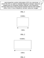
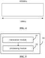
- FIGS. 2-4 are schematic diagrams illustrating carriers or BWPs with three types of bandwidth respectively. These small carriers or BWPs that are discontinuous may be scheduled by one DCI, so that a PDSCH or PUSCH may be mapped on at least one discontinuous frequency domain resource.
- the base station sends the DCI to the terminal.
- the DCI is used for scheduling the PDSCH or PUSCH.
- the frequency domain resource range(s) indicated by the first information field of the DCI include at least one of the carriers or BWPs illustrated in FIG. 2, FIG. 3 and FIG. 4 .
- the terminal determines, based on the first information field and the second information field, at least one scheduled frequency domain resource range, a size of bits for the frequency domain resource assignment on the scheduled frequency domain resource ranges and frequency domain resource assignment positions in the scheduled frequency domain resource ranges.
- the first frequency domain resource range may be a carrier illustrated in FIG. 2
- the second frequency domain resource range may be a carrier or BWP illustrated in FIG. 3 or 4
- the first frequency domain resource range is a frequency domain resource range of which bandwidth is the smallest among the at least one frequency domain resource range.
- the second information field of the DCI indicates to assign these scheduled frequency domain resources based on the bandwidth of the first frequency domain resource range, i.e., the bandwidth of 10M. That is, the size of bits for the frequency domain resource assignment is equal to the size of bits for the frequency domain resource indication determined based on the first frequency domain resource range.
- the frequency domain resources of 20MHz and 30MHz need to be mapped based on the size of bits for the frequency domain resource assignment of 10MHz.
- the terminal explains the bitmap indicated by the second information field.
- the throughput may be improved by using multiple carriers, a TB packet may be mapped on the discontinuous frequency domain resources, the complexity of processing multiple TB packets by the terminal may be reduced, and the addition of a new PDCCH may be avoided.
- the PUSCH sent by the terminal to the base station may be mapped on the same frequency domain resource as the PDSCH.
- the DCI is sent to the terminal.
- the DCI is used to indicate the frequency domain resource assignment for physical shared channel, and the frequency domain resources of the physical shared channel are located within one or more frequency domain resource ranges.
- the amount of DCI may be reduced to reduce network side signaling overhead while realizing flexible scheduling of single carrier/multi carriers/frequency domain resources/BWPs, to realize the mapping of a TB packet on discontinuous frequency domain resources, and reduce the complexity of the terminal in handling multiple TB packets.
- the size of the second information field may be determined, to reduce the number of load sizes of different DCI and to reduce the complexity of detecting the PDCCH at the terminal.
- Embodiments of the disclosure also provide a method for frequency domain resource assignment, which is applied to a terminal.
- the method includes: receiving DCI sent by a network side device, in which the DCI is used to indicate frequency domain resource assignment for physical shared channel, and frequency domain resources of the physical shared channel are located within one or more frequency domain resource ranges.
- the DCI includes a first information field and a second information field
- the first information field uses a bitmap or a codepoint to indicate the terminal the index(s) of the one or more scheduled frequency domain resource ranges.
- the frequency domain resource range(s) includes(include): a first frequency domain resource range with a minimum bandwidth and at least one second frequency domain resource range other than the first frequency domain resource range.
- a size of bits of the second information field is equal to a size of bits of resource assignment determined based on a bandwidth of the first frequency domain resource range.
- bits of the second information field correspond to RBGs of the second frequency domain resource range, in which
- the method applied to the terminal is corresponding to the above methods applied to the network side device, and all the implementations of realizing the above methods applied to the network side device are applicable to the method applied to the terminal and may achieve the same technical effects.
- inventions of the disclosure provide an apparatus 50 for frequency domain resource assignment which is applied to a network side device.
- the apparatus includes: a transceiver module 51, configured to send DCI to a terminal, in which the DCI is used to indicate frequency domain resource assignment for physical shared channel, and frequency domain resources of the physical shared channel are located within one or more frequency domain resource ranges.
- the DCI includes a first information field and a second information field
- the first information field uses a bitmap or a codepoint to indicate the index(s) of the one or more frequency domain resource ranges
- the frequency domain resource range(s) includes(include): a first frequency domain resource range with a minimum bandwidth and at least one second frequency domain resource range other than the first frequency domain resource range.
- a size of bits of the second information field is equal to a size of bits for resource assignment determined based on a bandwidth of the first frequency domain resource range.
- bits of the second information field correspond to RBGs of the second frequency domain resource range, in which
- the apparatus is an apparatus corresponding to the above method applied to the network side device, and all the implementations of realizing the method described above are applicable to the embodiments of the apparatus, and the same technical effects can also be achieved.
- the apparatus may also include a processing module 52 for processing data sent and received by the transceiver module 51.
- Embodiments of the disclosure provides an apparatus for frequency domain resource assignment, which is applied to a terminal.
- the apparatus includes: a transceiver module, configured to receive DCI sent by a network side device, in which the DCI is used to indicate frequency domain resource assignment for physical shared channel, and the frequency domain resources of the physical shared channel are located within one or more frequency domain resource ranges.
- the DCI includes a first information field and a second information field
- the first information field uses a bitmap or a codepoint to indicate the index(s) of the one or more frequency domain resource ranges.
- the frequency domain resource range(s) includes(include): a first frequency domain resource range with a minimum bandwidth and at least one second frequency domain resource range other than the first frequency domain resource range.
- a size of bits of the second information field is equal to a size of bits for resource assignment determined based on a bandwidth of the first frequency domain resource range.
- bits of the second information field correspond to RBGs of the second frequency domain resource range, in which
- the apparatus is an apparatus corresponding to the above method applied to the terminal, and all the implementations of realizing the method described above are applicable to the embodiments of the apparatus, and the same technical effects may also be achieved.
- Embodiments of the disclosure also provide a communication device, which includes a processor and a memory having a computer program stored thereon.
- a communication device which includes a processor and a memory having a computer program stored thereon.
- the computer program is executed by the processor, the methods as described above may be performed. All the implementations of method embodiments described above are applicable to this embodiment and may achieve the same technical effects.
- Embodiments of the disclosure also provide a computer readable storage medium having instructions stored thereon. When the instructions are executed by a computer, the computer is caused to perform the methods as described above. All the implementations of method embodiments described above are applicable to this embodiment and may achieve the same technical effects.
- the disclosed apparatuses and methods may be implemented in other ways.
- embodiments of the apparatus described above are merely illustrative.
- the classification of the units merely depends on logical functions, and there may be other classification methods in actual implementation.
- multiple units or components may be combined or integrated into another system, or some features may be ignored or may not be executed.
- the mutual coupling, direct coupling or communication connection shown or discussed may be an indirect coupling or a communication connection through some interfaces, devices or units, which may be electrical, mechanical or in other forms.
- the units described as separate components may or may not be physically separated, and the components shown as units may or may not be physical units, that is, they may be located in one place or distributed over multiple network units. Some or all of the units may be selected according to actual needs to achieve the purpose of the solution of this embodiment.
- each functional unit in each embodiment of the disclosure may be integrated into one processing unit, or each unit may exist physically separately, or two or more units may be integrated into one unit.
- the functions are implemented in the form of software functional units and sold or used as independent products, they can be stored in a computer-readable storage medium.
- the technical solution of the disclosure may essentially be embodied in the form of a software product, or the part that contributes to the related art or a part of the technical solution.
- the computer software product is stored in a storage medium and includes a number of instructions for enabling a computer device (which may be a personal computer, a server, or a network device, etc.) to execute all or part of the steps of the method described in each embodiment of the disclosure.
- the aforementioned storage medium includes: a USB flash drive, a mobile hard disk, a read only memory (ROM), a Random Access Memory (RAM), a disk or a CD-ROM, and various other mediums that can store program codes.
- each component or step can be decomposed and/or recombined.
- decompositions and/or recombinations should be regarded as equivalents of the disclosure.
- steps of executing the above series of processes can be naturally executed in a chronological order according to the described order, but they do not necessarily need to be executed in the chronological order, and some steps can be executed in parallel or independently.
- the objects of the disclosure may also be achieved by running a program or a group of programs on any computing device.
- the computing device may be a known general-purpose device. Therefore, the object of the disclosure can also be achieved by merely providing a program product including a program code for implementing the method or apparatus. That is, such a program product also constitutes the disclosure, and a storage medium that stores such a program product also constitutes the disclosure. Obviously, the storage medium may be any known storage medium or any storage medium developed in the future. It should also be noted that, in the apparatus and method of the disclosure, it is apparent that each component or step can be decomposed and/or recombined. These decompositions and/or recombinations should be regarded as equivalents of the disclosure. Moreover, the steps of executing the above series of processes can be naturally executed in a chronological order according to the described order, but do not necessarily need to be executed in the chronological order. Certain steps may be performed in parallel or independently.
Landscapes
- Engineering & Computer Science (AREA)
- Signal Processing (AREA)
- Computer Networks & Wireless Communication (AREA)
- Mobile Radio Communication Systems (AREA)
Abstract
Description
- This application claims priority to
Chinese patent application No. 202111342504.8, filed on November 12, 2021 - The disclosure relates to a field of communication technology, in particular to methods for frequency domain resource assignment, apparatuses frequency domain resource assignment and related devices.
- Currently, there are many discontinuous spectrums with smaller bandwidths in New Radio (NR). According to the previous spectrum usage, a terminal can only perform carrier aggregation of these carriers, and a Transport Block (TB) can still only be transmitted within one carrier. Since the bandwidth of each carrier is very small and cannot support a larger TB size, for a service packet, the base station can only split it into multiple small TBs for transmission, and multiple physical downlink control channels (PDCCHs) are required for scheduling respectively, resulting in relatively large PDCCH overhead. The throughput of carrier usage is limited by the fact that the bandwidth of each carrier is very small, and also by the inability to support a PDCCH with a larger aggregation level.
- The technical problem to be solved by the disclosure is to provide methods and apparatuses for frequency domain resource assignment and related devices, to realize scheduling for multiple different frequency domain resources through one downlink control information (DCI), improve a throughput of carrier usage, and reduce an overhead of a physical downlink control channel (PDCCH).
- In order to solve the above technical problem, the technical solutions of the disclosure are provided as follows.
- According to a first aspect of embodiments of the disclosure, a method for frequency domain resource assignment, applied to a network side device, is provided. The method includes:
sending downlink control information (DCI) to a terminal, in which the DCI is used to indicate frequency domain resource assignment for physical shared channel, and frequency domain resource of the physical shared channel are located within one or more frequency domain resource ranges. - In some embodiments, the DCI includes a first information field and a second information field;
- the first information field is used to indicate index(s) of the one or more frequency domain resource ranges where the frequency domain resources of the physical shared channel are located in; and
- the second information field is used to indicate the frequency domain resource assignment within a frequency domain resource range.
- In some embodiments, the first information field adopts a bitmap or a codepoint to indicate the index(s) of the one or more frequency domain resource ranges.
- In some embodiments, the frequency domain resource range(s) includes(include): a first frequency domain resource range with a minimum bandwidth and at least one second frequency domain resource range other than the first frequency domain resource range.
- In some embodiments, a size of bits of the second information field is equal to a size of bits for resource assignment determined based on a bandwidth of the first frequency domain resource range.
- In some embodiments, when the frequency domain resource assignment is type 1, a start resource block (RB) of the second frequency domain resource range corresponding to a resource indication value (RIV) included in the second information field is:

- a number of RBs that are consecutively assigned is

- in which,

- K represents a ratio of a bandwidth of the second frequency domain resource range to a bandwidth of the first frequency domain resource range.
- In some embodiments, when the frequency domain resource assignment is type 0, bits of the second information field correspond to resource block groups (RBGs) of the second frequency domain resource range, in which
- a size of a first RBG is

- if


- where P represents a size of RBG of the first frequency domain resource range, K represents a ratio of a bandwidth of the second frequency domain resource range to a bandwidth of the first frequency domain resource range;


- According to a second aspect of embodiments of the disclosure, a method for frequency domain resource assignment, applied to a terminal, is provided. The method includes:
receiving downlink control information (DCI) sent by a network side device, in which the DCI is used to indicate frequency domain resource assignment for physical shared channel, and frequency domain resources of the physical shared channel are located within one or more frequency domain resource ranges. - In some embodiments, the DCI includes a first information field and a second information field;
- the first information field is used to indicate index(s) of the one or more frequency domain resource ranges where the frequency domain resources of the physical shared channel are located in; and
- the second information field is used to indicate the frequency domain resource assignment within a frequency domain resource range.
- In some embodiments, the first information field adopts a bitmap or a codepoint to indicate the terminal the index(s) of the one or more scheduled frequency domain resource ranges.
- In some embodiments, the frequency domain resource range(s) includes(include): a first frequency domain resource range with a minimum bandwidth and at least one second frequency domain resource range other than the first frequency domain resource range.
- In some embodiments, a size of bits of the second information field is equal to a size of bits for resource assignment determined based on a bandwidth of the first frequency domain resource range.
- In some embodiments, when the frequency domain resource assignment is type 1, a start resource block (RB) of the second frequency domain resource range corresponding to a resource indication value (RIV) included in the second information field is:

- a number of RBs that are consecutively assigned is

- in which,

- K represents a ratio of a bandwidth of the second frequency domain resource range to a bandwidth of the first frequency domain resource range.
- In some embodiments, when the frequency domain resource assignment is type 0, bits of the second information field corresponds to RBGs of the second frequency domain resource range, in which
- a size of a first RBG is

- if


- where P represents a size of RBG of the first frequency domain resource range, K represents a ratio of a bandwidth of the second frequency domain resource range to a bandwidth of the first frequency domain resource range;


- According to a third aspect of embodiments of the disclosure, an apparatus for frequency domain resource assignment, applied to a network side device, is provided. The apparatus includes:
a transceiver module, configured to send downlink control information (DCI) to a terminal, in which the DCI is used to indicate frequency domain resource assignment for physical shared channel, and frequency domain resources of the physical shared channel are located within one or more frequency domain resource ranges. - According to a fourth aspect of embodiments of the disclosure, an apparatus for frequency domain resource assignment, applied to a terminal, is provided. The apparatus includes:
a transceiver module, configured to receive downlink control information (DCI) sent by a network side device, in which the DCI is used to indicate frequency domain resource assignment for physical shared channel, and frequency domain resources of the physical shared channel are located within one or more frequency domain resource ranges. - According to a fifth aspect of embodiments of the disclosure, a communication device is provided, which includes a processor and a memory having a computer program stored thereon. When the computer program is executed by the processor, any of the above methods is performed.
- According to a sixth aspect of embodiments of the disclosure, a computer-readable storage medium having instructions stored thereon is provided. When the instructions are executed by a computer, the computer is caused to perform any of the above methods.
- The above solutions of the disclosure at least include the following beneficial effects.
- The DCI is sent to the terminal. The DCI is used to indicate the frequency domain resource assignment for physical shared channel, and frequency domain resources of the physical shared channel are located within one or more frequency domain resource ranges. Therefore, the scheduling for multiple different frequency domain resources is realized using one DCI, the throughput of carrier usage is improved, the overhead of a PDCCH is reduced, and the user experience and network performance are enhanced.
-
-
FIG. 1 is a flowchart illustrating a method for frequency domain resource assignment according to an embodiment of the disclosure. -
FIG. 2 is a schematic diagram illustrating a spectrum of a first type of bandwidth according to an embodiment of the disclosure. -
FIG. 3 is a schematic diagram illustrating a spectrum of a second type of bandwidth according to an embodiment of the disclosure. -
FIG. 4 is a schematic diagram illustrating a spectrum of a third type of bandwidth according to an embodiment of the disclosure. -
FIG. 5 is a schematic diagram illustrating modules of an apparatus for frequency domain resource assignment according to an embodiment of the disclosure. - Embodiments of the disclosure will be described in detail below with reference to the accompanying drawings. Although the embodiments of the disclosure are shown in the accompanying drawings, it is understandable that the disclosure may be realized in various forms instead of being limited by embodiments set forth herein. Instead, these embodiments are provided to enable a more thorough understanding of the disclosure and to convey the scope of the disclosure completely to those skilled in the art.
- As illustrated in
FIG. 1 , embodiments of the disclosure provide a method for frequency domain resource assignment, which is applied to a network side device. The method includes ablock 11. - At
block 11, downlink control information (DCI) is sent to a terminal, in which the DCI is used to indicate frequency domain resource assignment for physical shared channel, and frequency domain resources of the physical shared channel are located within one or more frequency domain resource ranges. - In this embodiment, the DCI may be sent to the terminal. The DCI is used to indicate the frequency domain resource assignment for the physical shared channel, and the frequency domain resources of the physical shared channel are located within one or more frequency domain resource ranges. The scheduling for multiple different frequency domain resource ranges may be realized using one DCI, to improve the throughput of carrier usage and reduce the overhead of a physical downlink control channel (PDCCH).
- In an optional embodiment of the disclosure, in
block 11, the DCI includes a first information field and a second information field. - The first information field is used to indicate index(s) of the one or more frequency domain resource ranges where the frequency domain resources of the physical shared channel are located in.
- The second information field is used to indicate the frequency domain resource assignment within a frequency domain resource range.
- The frequency domain resource range is a carrier or a Bandwidth Part (BWP).
- In this embodiment, in detail, the second information field is used for indicating the frequency domain resource assignment for Physical Downlink Shared Channel (PDSCH) or Physical Uplink Shared Channel (PUSCH) within one carrier or BWP. The second information field is shared by multiple frequency domain resource ranges. In other words, multiple frequency domain resource ranges all refer to the frequency domain resource assignment indicated by the second information field, which saves the load size of the PDCCH and improves the throughput of the PDCCH.
- In an optional embodiment of the disclosure, the first information field uses a bitmap or a codepoint to indicate the index(s) of the one or more frequency domain resource ranges.
- In this embodiment, the first information field uses a bitmap or a codepoint to indicate the index(s) of at least one frequency domain resource range where the actually scheduled PDSCH or PUSCH is located in. For example, when there are 5 carriers or BWPs, a 5-bitmap may be used to indicate which carriers or BWPs are scheduled.
- When actually scheduling at least two target frequency domain resources, it is also possible that some carriers or BWPs are combined or configured at the base station, and then the combined or configured index is indicated through the first information field.
- In an optional embodiment of the disclosure, the frequency domain resource range includes: a first frequency domain resource range with a minimum bandwidth and at least one second frequency domain resource range other than the first frequency domain resource range.
- In this embodiment, the first frequency domain resource range is a frequency domain resource range of which the bandwidth is the minimum between at least two frequency domain resource ranges.
- In an optional embodiment of the disclosure, a size of bits of the second information field is equal to a size of bits for resource assignment determined based on a bandwidth of the first frequency domain resource range.
- In this embodiment, the terminal determines at least one scheduled frequency domain resource range and the frequency domain resource assignment in the at least one scheduled frequency domain resource range based on the first information field and the second information field. The frequency domain resource assignment for the physical channel within each of multiple scheduled frequency domain resource ranges may be all referred to an indication of the second information field. Considering that the bandwidth sizes of the multiple frequency domain resource ranges may be different, the size of the second information field in this embodiment is determined based on the bandwidth of the minimum frequency domain resource range. That is, the size of the second information field is fixed and the load size of the DCI is also fixed, regardless of the index(s) of the scheduled frequency domain resource range(s) indicated by the first information field, thereby simplifying the complexity of receiving, by the terminal, the PDCCH.
- In an optional embodiment of the disclosure, when the frequency domain resource assignment is type 1 (i.e., continuous resource assignment), a start resource block (RB) of the second frequency domain resource range corresponding to a resource indication value (RIV) included in the second information field is:

- a number of RBs that are consecutively assigned is

- where,

- K represents a ratio of a bandwidth of the second frequency domain resource range to a bandwidth of the first frequency domain resource range, e.g.,

- In this embodiment, the scheduled frequency domain resource range(s) indicated in the first information field includes(include) a second frequency domain resource range. For the second frequency domain resource range, a frequency domain resource position occupied by a scheduled PDSCH or PUSCH within the second frequency domain resource range is determined using the above method.
- When the scheduled frequency domain resource range(s) indicated in the first information field includes(include) the first frequency domain resource range, for the first frequency domain resource range, the frequency domain resource position occupied by a scheduled PDSCH or PUSCH within the first frequency domain resource range is determined based on a relevant method.
- In an optional embodiment of the disclosure, when the frequency domain resource assignment is type 0 (i.e., discontinuous resource assignment), bits of the second information field correspond to resource block groups (RBGs) of the second frequency domain resource range, in which,
- a size of a first RBG is

- if


- where P represents a size of RBG of the first frequency domain resource range, K represents a ratio of a bandwidth of the second frequency domain resource range to a bandwidth of the first frequency domain resource range;


- In this embodiment, the scheduled frequency domain resource range(s) indicated in the first information field includes(include) a second frequency domain resource range. For the second frequency domain resource range, the frequency domain resource position occupied by a scheduled PDSCH or PUSCH within the second frequency domain resource range is determined by the method described above.
- When the scheduled frequency domain resource range(s) indicated in the first information field includes(include) a first frequency domain resource range, for the first frequency domain resource range, the frequency domain resource position occupied by a scheduled PDSCH or PUSCH within the first frequency domain resource range is determined based on a preset method.
- As illustrated in
FIGS. 2-4 , currently, there are many discontinuous spectrums with smaller bandwidths in the NR network.FIGS. 2-4 are schematic diagrams illustrating carriers or BWPs with three types of bandwidth respectively. These small carriers or BWPs that are discontinuous may be scheduled by one DCI, so that a PDSCH or PUSCH may be mapped on at least one discontinuous frequency domain resource. - For example, the base station sends the DCI to the terminal. The DCI is used for scheduling the PDSCH or PUSCH. The frequency domain resource range(s) indicated by the first information field of the DCI include at least one of the carriers or BWPs illustrated in
FIG. 2, FIG. 3 andFIG. 4 . The terminal determines, based on the first information field and the second information field, at least one scheduled frequency domain resource range, a size of bits for the frequency domain resource assignment on the scheduled frequency domain resource ranges and frequency domain resource assignment positions in the scheduled frequency domain resource ranges. - The first frequency domain resource range may be a carrier illustrated in
FIG. 2 , and the second frequency domain resource range may be a carrier or BWP illustrated inFIG. 3 or4 . The first frequency domain resource range is a frequency domain resource range of which bandwidth is the smallest among the at least one frequency domain resource range. The second information field of the DCI indicates to assign these scheduled frequency domain resources based on the bandwidth of the first frequency domain resource range, i.e., the bandwidth of 10M. That is, the size of bits for the frequency domain resource assignment is equal to the size of bits for the frequency domain resource indication determined based on the first frequency domain resource range. - For the second frequency domain resource range illustrated in
FIGS. 3 and4 , if the first information filed indicates that the scheduled frequency domain resource range(s) includes(include) the frequency domain resource range illustrated inFIGS. 3 and/or 4, the frequency domain resources of 20MHz and 30MHz need to be mapped based on the size of bits for the frequency domain resource assignment of 10MHz. When mapping, - The terminal explains the RIV indicated by the second information field, in which a start RB corresponding to the RIV is:





- For example, for the frequency domain resource range illustrated in
FIG. 3 , K = 2; and for the frequency domain resource range illustrated inFIG. 4 , K = 3. - The terminal explains the bitmap indicated by the second information field.
- Bits of the second information field correspond to RBGs of the second frequency domain resource range, in which, a size of a first RBG is

- if


- where P represents a size of a RBG of the first frequency domain resource range, K represents a ratio of a bandwidth of the second frequency domain resource range to a bandwidth of the first frequency domain resource range, e.g.,


- For example, for the frequency domain resource range illustrated in
FIG. 3 , K = 2; and for the frequency domain resource range illustrated inFIG. 4 , K = 3. - In this way, the throughput may be improved by using multiple carriers, a TB packet may be mapped on the discontinuous frequency domain resources, the complexity of processing multiple TB packets by the terminal may be reduced, and the addition of a new PDCCH may be avoided. In addition, the PUSCH sent by the terminal to the base station may be mapped on the same frequency domain resource as the PDSCH.
- In above embodiments of the disclosure, the DCI is sent to the terminal. The DCI is used to indicate the frequency domain resource assignment for physical shared channel, and the frequency domain resources of the physical shared channel are located within one or more frequency domain resource ranges. The amount of DCI may be reduced to reduce network side signaling overhead while realizing flexible scheduling of single carrier/multi carriers/frequency domain resources/BWPs, to realize the mapping of a TB packet on discontinuous frequency domain resources, and reduce the complexity of the terminal in handling multiple TB packets. Through the definitions of the first frequency domain resource range and the second frequency domain resource range, the size of the second information field may be determined, to reduce the number of load sizes of different DCI and to reduce the complexity of detecting the PDCCH at the terminal.
- Embodiments of the disclosure also provide a method for frequency domain resource assignment, which is applied to a terminal. The method includes:
receiving DCI sent by a network side device, in which the DCI is used to indicate frequency domain resource assignment for physical shared channel, and frequency domain resources of the physical shared channel are located within one or more frequency domain resource ranges. - In some examples, the DCI includes a first information field and a second information field;
- the first information field is used to indicate index(s) of the one or more frequency domain resource ranges where the frequency domain resources of the physical shared channel are located in; and
- the second information field is used to indicate frequency domain resource assignment within a frequency domain resource range.
- In some examples, the first information field uses a bitmap or a codepoint to indicate the terminal the index(s) of the one or more scheduled frequency domain resource ranges.
- In some examples, the frequency domain resource range(s) includes(include): a first frequency domain resource range with a minimum bandwidth and at least one second frequency domain resource range other than the first frequency domain resource range.
- In some examples, a size of bits of the second information field is equal to a size of bits of resource assignment determined based on a bandwidth of the first frequency domain resource range.
- In some examples, when the frequency domain resource assignment is type 1, a start RB of the second frequency domain resource range corresponding to a RIV included in the second information field is:

- a number of RBs that are continuously assigned is

- where,

- K represents a ratio of a bandwidth of the second frequency domain resource range to a bandwidth of the first frequency domain resource range.
- In some examples, when the frequency domain resource assignment is type 0, bits of the second information field correspond to RBGs of the second frequency domain resource range, in which
- a size of a first RBG is

- if


- where P represents a size of a RBG of the first frequency domain resource range, K represents a ratio of a bandwidth of the second frequency domain resource range to a bandwidth of the first frequency domain resource range;


- It is noteworthy that the method applied to the terminal is corresponding to the above methods applied to the network side device, and all the implementations of realizing the above methods applied to the network side device are applicable to the method applied to the terminal and may achieve the same technical effects.
- As illustrated in
FIG. 5 , embodiments of the disclosure provide anapparatus 50 for frequency domain resource assignment which is applied to a network side device. The apparatus includes:
atransceiver module 51, configured to send DCI to a terminal, in which the DCI is used to indicate frequency domain resource assignment for physical shared channel, and frequency domain resources of the physical shared channel are located within one or more frequency domain resource ranges. - In some examples, the DCI includes a first information field and a second information field;
- the first information field is used to indicate index(s) of the one or more frequency domain resource ranges where the frequency domain resources of the physical shared channel are located in; and
- the second information field is used to indicate frequency domain resource assignment within a frequency domain resource range.
- In some examples, the first information field uses a bitmap or a codepoint to indicate the index(s) of the one or more frequency domain resource ranges
- In some examples, the frequency domain resource range(s) includes(include): a first frequency domain resource range with a minimum bandwidth and at least one second frequency domain resource range other than the first frequency domain resource range.
- In some examples, a size of bits of the second information field is equal to a size of bits for resource assignment determined based on a bandwidth of the first frequency domain resource range.
- In some examples, when the frequency domain resource assignment is type 1, a start RB of the second frequency domain resource range corresponding to a RIV included in the second information field is:

- a number of RBs that are continuously assigned is

- where,

- K represents a ratio of a bandwidth of the second frequency domain resource range to a bandwidth of the first frequency domain resource range.
- In some examples, when the frequency domain resource assignment is type 0, bits of the second information field correspond to RBGs of the second frequency domain resource range, in which
- a size of a first RBG is

- if


- where P represents a size of a RBG of the first frequency domain resource range, K represents a ratio of a bandwidth of the second frequency domain resource range to a bandwidth of the first frequency domain resource range;


- It is noteworthy that the apparatus is an apparatus corresponding to the above method applied to the network side device, and all the implementations of realizing the method described above are applicable to the embodiments of the apparatus, and the same technical effects can also be achieved. The apparatus may also include a
processing module 52 for processing data sent and received by thetransceiver module 51. - Embodiments of the disclosure provides an apparatus for frequency domain resource assignment, which is applied to a terminal. The apparatus includes: a transceiver module, configured to receive DCI sent by a network side device, in which the DCI is used to indicate frequency domain resource assignment for physical shared channel, and the frequency domain resources of the physical shared channel are located within one or more frequency domain resource ranges.
- In some examples, the DCI includes a first information field and a second information field;
- the first information field is used to indicate index(s) of the one or more frequency domain resource ranges where the frequency domain resources of the physical shared channel are located in; and
- the second information field is used to indicate the frequency domain resource assignment within a frequency domain resource range.
- In some examples, the first information field uses a bitmap or a codepoint to indicate the index(s) of the one or more frequency domain resource ranges.
- In some examples, the frequency domain resource range(s) includes(include): a first frequency domain resource range with a minimum bandwidth and at least one second frequency domain resource range other than the first frequency domain resource range.
- In some examples, a size of bits of the second information field is equal to a size of bits for resource assignment determined based on a bandwidth of the first frequency domain resource range.
- In some examples, when the frequency domain resource assignment is type 1, a start RB of the second frequency domain resource range corresponding to a RIV included in the second information field is:

- a number of RBs that are continuously assigned is

- in which

- K represents a ratio of a bandwidth of the second frequency domain resource range to a bandwidth of the first frequency domain resource range.
- In some examples, when the frequency domain resource assignment is type 0, bits of the second information field correspond to RBGs of the second frequency domain resource range, in which
- a size of a first RBG is

- if


- where P represents a size of a RBG of the first frequency domain resource range, K represents a ratio of a bandwidth of the second frequency domain resource range to a bandwidth of the first frequency domain resource range;


- It is noteworthy that the apparatus is an apparatus corresponding to the above method applied to the terminal, and all the implementations of realizing the method described above are applicable to the embodiments of the apparatus, and the same technical effects may also be achieved.
- Embodiments of the disclosure also provide a communication device, which includes a processor and a memory having a computer program stored thereon. When the computer program is executed by the processor, the methods as described above may be performed. All the implementations of method embodiments described above are applicable to this embodiment and may achieve the same technical effects.
- Embodiments of the disclosure also provide a computer readable storage medium having instructions stored thereon. When the instructions are executed by a computer, the computer is caused to perform the methods as described above. All the implementations of method embodiments described above are applicable to this embodiment and may achieve the same technical effects.
- Those skilled in the art will appreciate that the units and algorithm steps of each example described in combination with the embodiments disclosed herein may be implemented by an electronic hardware, or a combination of computer software and the electronic hardware. Whether these functions are performed by hardware or software depends on the specific applications of the technical solution and the design constraints. Those skilled in the art may use different methods to implement the described functions for each specific application, but such implementations should not be considered to be beyond the scope of the disclosure.
- Those skilled in the art can clearly understand that, for convenience and brevity of description, the specific working processes of the systems, devices and units described above can refer to the corresponding processes in the aforementioned method embodiments and will not be repeated here.
- In embodiments according to the disclosure, it is understandable that the disclosed apparatuses and methods may be implemented in other ways. For example, embodiments of the apparatus described above are merely illustrative. For example, the classification of the units merely depends on logical functions, and there may be other classification methods in actual implementation. For example, multiple units or components may be combined or integrated into another system, or some features may be ignored or may not be executed. Moreover, the mutual coupling, direct coupling or communication connection shown or discussed may be an indirect coupling or a communication connection through some interfaces, devices or units, which may be electrical, mechanical or in other forms.
- The units described as separate components may or may not be physically separated, and the components shown as units may or may not be physical units, that is, they may be located in one place or distributed over multiple network units. Some or all of the units may be selected according to actual needs to achieve the purpose of the solution of this embodiment.
- In addition, each functional unit in each embodiment of the disclosure may be integrated into one processing unit, or each unit may exist physically separately, or two or more units may be integrated into one unit.
- If the functions are implemented in the form of software functional units and sold or used as independent products, they can be stored in a computer-readable storage medium. Based on such understanding, the technical solution of the disclosure may essentially be embodied in the form of a software product, or the part that contributes to the related art or a part of the technical solution. The computer software product is stored in a storage medium and includes a number of instructions for enabling a computer device (which may be a personal computer, a server, or a network device, etc.) to execute all or part of the steps of the method described in each embodiment of the disclosure. The aforementioned storage medium includes: a USB flash drive, a mobile hard disk, a read only memory (ROM), a Random Access Memory (RAM), a disk or a CD-ROM, and various other mediums that can store program codes.
- In addition, it should be noted that, in the apparatus and method of the disclosure, obviously, each component or step can be decomposed and/or recombined. These decompositions and/or recombinations should be regarded as equivalents of the disclosure. Moreover, the steps of executing the above series of processes can be naturally executed in a chronological order according to the described order, but they do not necessarily need to be executed in the chronological order, and some steps can be executed in parallel or independently. For those skilled in the art, it is understood that all or any steps or components of the methods and devices disclosed herein can be implemented by a hardware, a firmware, software, or a combination thereof in any computing devices (e.g., a processor, and a storage medium) or a network of the computing devices, which can be implemented by those skilled in the art using their basic programming skills after reading the description of the disclosure.
- Therefore, the objects of the disclosure may also be achieved by running a program or a group of programs on any computing device. The computing device may be a known general-purpose device. Therefore, the object of the disclosure can also be achieved by merely providing a program product including a program code for implementing the method or apparatus. That is, such a program product also constitutes the disclosure, and a storage medium that stores such a program product also constitutes the disclosure. Obviously, the storage medium may be any known storage medium or any storage medium developed in the future. It should also be noted that, in the apparatus and method of the disclosure, it is apparent that each component or step can be decomposed and/or recombined. These decompositions and/or recombinations should be regarded as equivalents of the disclosure. Moreover, the steps of executing the above series of processes can be naturally executed in a chronological order according to the described order, but do not necessarily need to be executed in the chronological order. Certain steps may be performed in parallel or independently.
- The above embodiments are preferred embodiments of the disclosure. It should be noted that for those skilled in the art, several improvements and modifications can be made without departing from the principles described in the disclosure. These improvements and modifications should also be regarded as the scope of protection of the disclosure.
Claims (18)
- A method for frequency domain resource assignment, applied to a network side device, comprising:
sending downlink control information (DCI) to a terminal, wherein the DCI is used to indicate frequency domain resource assignment for physical shared channel, and frequency domain resources of the physical shared channel are located within one or more frequency domain resource ranges. - The method of claim 1, wherein the DCI comprises a first information field and a second information field;the first information field is used to indicate index(s) of the one or more frequency domain resource ranges where the frequency domain resources of the physical shared channel are located in; andthe second information field is used to indicate the frequency domain resource assignment within a frequency domain resource range.
- The method of claim 2, wherein the first information field uses a bitmap or a codepoint to indicate the index(s) of the one or more frequency domain resource ranges.
- The method of claim 2, wherein the one or more frequency domain resource ranges comprise: a first frequency domain resource range with a minimum bandwidth and at least one second frequency domain resource range other than the first frequency domain resource range.
- The method of claim 2 or 4, wherein a size of bits of the second information field is equal to a size of bits for a resource assignment determined based on a bandwidth of the first frequency domain resource range.
- The method of claim 4, wherein when the frequency domain resource assignment is type 1, a start resource block (RB) of the second frequency domain resource range corresponding to a resource indication value (RIV) included in the second information field is:
 a number of RBs that are consecutively assigned is
 where,
 K represents a ratio of a bandwidth of the second frequency domain resource range to a bandwidth of the first frequency domain resource range.
 - The method of claim 4, wherein when the frequency domain resource assignment is type 0, bits of the second information field correspond to resource block groups (RBGs) of the second frequency domain resource range, wherein,a size of a first RBG is
 if
if

 where P represents a size of a RBG of the first frequency domain resource range, K represents a ratio of a bandwidth of the second frequency domain resource range to a bandwidth of the first frequency domain resource range;

- A method for frequency domain resource assignment, applied to a terminal, comprising:
receiving downlink control information (DCI) sent by a network side device, wherein the DCI is used to indicate frequency domain resource assignment for physical shared channel, and frequency domain resources of the physical shared channel are located within one or more frequency domain resource ranges. - The method of claim 8, wherein the DCI comprises a first information field and a second information field;the first information field is used to indicate index(s) of the one or more frequency domain resource ranges where the frequency domain resources of the physical shared channel are located in; andthe second information field is used to indicate the frequency domain resource assignment within a frequency domain resource range.
- The method of claim 9, wherein the first information field uses a bitmap or a codepoint to indicate the terminal the index(s) of one or more scheduled frequency domain resource ranges .
- The method of claim 9, wherein the one or more frequency domain resource ranges comprise: a first frequency domain resource range with minimum bandwidth and at least one second frequency domain resource range other than the first frequency domain resource range.
- The method of claim 9 or 11, wherein a size of bits of the second information field is equal to a size of bits for resource assignment determined based on a bandwidth of the first frequency domain resource range.
- The method of claim 12, wherein when the frequency domain resource assignment is type 1, a start resource block (RB) of the second frequency domain resource range corresponding to a resource indication value (RIV) included in the second information field is:
 a number of RBs that are consecutively assigned is
 where,
 K represents a ratio of a bandwidth of the second frequency domain resource range to the bandwidth of the first frequency domain resource range.
 - The method of claim 12, wherein when the frequency domain resource assignment is type 0, bits of the second information field correspond to resource block groups (RBGs) of the second frequency domain resource range,wherein a size of a first RBG is
 if
if

 where P represents a size of RBG of the first frequency domain resource range, K represents a ratio of a bandwidth of the second frequency domain resource range to the bandwidth of the first frequency domain resource range;

- An apparatus for frequency domain resource assignment, applied to a network side device, comprising:
a transceiver module, configured to send downlink control information (DCI) to a terminal, wherein the DCI is used to indicate frequency domain resource assignment for physical shared channel, and frequency domain resources of the physical shared channel are located within one or more frequency domain resource ranges. - An apparatus for frequency domain resource assignment, applied to a terminal, comprising:
a transceiver module, configured to receive downlink control information (DCI) sent by a network side device, wherein the DCI is used to indicate frequency domain resource assignment for physical shared channel, and frequency domain resources of the physical shared channel are located within one or more frequency domain resource ranges. - A communication device comprising: a processor and a memory having a computer program stored thereon, wherein when the computer program is executed by the processor, the method of any one of claims 1 to 7 or the method of any one of claims 8 to 14 is performed.
- A computer-readable storage medium having instructions stored thereon, wherein when the instructions are executed by a computer, the method of any one of claims 1 to 7 or the method of any one of claims 8 to 14 is performed.
Applications Claiming Priority (2)
| Application Number | Priority Date | Filing Date | Title |
|---|---|---|---|
| CN202111342504.8A CN116133123B (en) | 2021-11-12 | 2021-11-12 | A method, apparatus and equipment for frequency domain resource allocation |
| PCT/CN2022/131738 WO2023083350A1 (en) | 2021-11-12 | 2022-11-14 | Frequency domain resource allocation method and apparatus, and device |
Publications (2)
| Publication Number | Publication Date |
|---|---|
| EP4432755A1 true EP4432755A1 (en) | 2024-09-18 |
| EP4432755A4 EP4432755A4 (en) | 2025-11-19 |
Family
ID=86301385
Family Applications (1)
| Application Number | Title | Priority Date | Filing Date |
|---|---|---|---|
| EP22892143.3A Pending EP4432755A4 (en) | 2021-11-12 | 2022-11-14 | METHOD AND DEVICE FOR ALLOCATION OF FREQUENCY RANGE RESOURCES AND DEVICE |
Country Status (7)
| Country | Link |
|---|---|
| EP (1) | EP4432755A4 (en) |
| JP (1) | JP7787992B2 (en) |
| CN (1) | CN116133123B (en) |
| AU (1) | AU2022387711B2 (en) |
| CA (1) | CA3237972A1 (en) |
| MX (1) | MX2024005690A (en) |
| WO (1) | WO2023083350A1 (en) |
Families Citing this family (1)
| Publication number | Priority date | Publication date | Assignee | Title |
|---|---|---|---|---|
| WO2025197141A1 (en) * | 2024-03-22 | 2025-09-25 | パナソニックIpマネジメント株式会社 | Member replacement device |
Family Cites Families (17)
| Publication number | Priority date | Publication date | Assignee | Title |
|---|---|---|---|---|
| WO2018126453A1 (en) * | 2017-01-06 | 2018-07-12 | 广东欧珀移动通信有限公司 | Handover method, base station, and terminal |
| US12022474B2 (en) * | 2017-06-16 | 2024-06-25 | Apple Inc. | Frequency domain resource allocation for downlink (DL) and uplink (UL) in new radio (NR) |
| CN109391417B (en) * | 2017-08-11 | 2022-05-13 | 华为技术有限公司 | Method, device and system for transmitting downlink control information |
| FI3740002T3 (en) * | 2018-01-13 | 2023-08-25 | Wilus Inst Standards & Tech Inc | Wireless communication system resource allocation method, device and system |
| US10602519B2 (en) * | 2018-04-06 | 2020-03-24 | Telefonaktiebolaget Lm Ericsson (Publ) | Bandwidth part switching |
| JP6913129B2 (en) * | 2018-07-27 | 2021-08-04 | 華碩電腦股▲ふん▼有限公司 | Methods and devices for power saving methods when receiving PDSCH (Physical Downlink Shared Channel) in wireless communication systems |
| CN110798298B (en) * | 2018-08-03 | 2021-11-02 | 维沃移动通信有限公司 | Control information indication, receiving method and device |
| CN110830194B (en) * | 2018-08-08 | 2020-10-30 | 北京紫光展锐通信技术有限公司 | Indication and determination method of uplink channel resource, base station, terminal and medium |
| CN110944388A (en) * | 2018-09-21 | 2020-03-31 | 电信科学技术研究院有限公司 | Frequency domain resource indicating and determining method, network equipment and terminal |
| CN111836378B (en) * | 2019-08-15 | 2023-07-25 | 维沃移动通信有限公司 | Frequency domain resource allocation method, network side equipment and terminal |
| CN112787781B (en) * | 2019-11-08 | 2024-01-23 | 中国移动通信有限公司研究院 | Resource allocation method, resource determination method, network equipment and terminal |
| KR102921267B1 (en) * | 2019-12-24 | 2026-02-03 | 삼성전자 주식회사 | Method and apparatus for user equipment power saving in wireless communication system |
| KR102922008B1 (en) * | 2020-01-16 | 2026-02-02 | 삼성전자주식회사 | Method and apparatus for transmitting and receiving downlink control information in a wireless communication system |
| CN115104277B (en) * | 2020-02-12 | 2024-04-05 | 苹果公司 | Method and apparatus for multi-component carrier physical downlink shared channel scheduling in wireless communications |
| KR102797008B1 (en) * | 2020-02-14 | 2025-04-18 | 엘지전자 주식회사 | Method for providing content and device |
| CN113630873B (en) * | 2020-05-08 | 2024-10-29 | 维沃移动通信有限公司 | Frequency domain resource allocation method and device |
| CN113630874B (en) * | 2020-05-08 | 2024-11-12 | 维沃移动通信有限公司 | Frequency domain resource allocation method and device |
-
2021
- 2021-11-12 CN CN202111342504.8A patent/CN116133123B/en active Active
-
2022
- 2022-11-14 CA CA3237972A patent/CA3237972A1/en active Pending
- 2022-11-14 WO PCT/CN2022/131738 patent/WO2023083350A1/en not_active Ceased
- 2022-11-14 AU AU2022387711A patent/AU2022387711B2/en active Active
- 2022-11-14 JP JP2024527582A patent/JP7787992B2/en active Active
- 2022-11-14 MX MX2024005690A patent/MX2024005690A/en unknown
- 2022-11-14 EP EP22892143.3A patent/EP4432755A4/en active Pending
Also Published As
| Publication number | Publication date |
|---|---|
| CN116133123A (en) | 2023-05-16 |
| JP7787992B2 (en) | 2025-12-17 |
| WO2023083350A1 (en) | 2023-05-19 |
| MX2024005690A (en) | 2024-06-19 |
| CA3237972A1 (en) | 2023-05-19 |
| AU2022387711B2 (en) | 2025-07-03 |
| EP4432755A4 (en) | 2025-11-19 |
| JP2024542428A (en) | 2024-11-15 |
| AU2022387711A1 (en) | 2024-05-30 |
| CN116133123B (en) | 2026-03-24 |
Similar Documents
| Publication | Publication Date | Title |
|---|---|---|
| US11991669B2 (en) | Feedback control channel configuration method and device | |
| KR102508791B1 (en) | Communication method and device | |
| US12150133B2 (en) | Uplink control information sending method, uplink control information receiving method, apparatus, and system | |
| US11395291B2 (en) | Allocating transmission resources in communication networks that provide low latency services | |
| US10660073B2 (en) | Allocation scheme for a physical uplink control channel utilized by network node user devices capable of carrier aggregation | |
| EP3678433A1 (en) | Method for determining resource allocation and indicating resource allocation, terminal and network-side equipment | |
| EP3379752A1 (en) | Downlink control information (dci) transmission method and device | |
| EP3840500A1 (en) | Method and device for determining and configuring scheduling request resource, and storage medium | |
| WO2019105341A1 (en) | Data sending method and device, and data receiving method and device | |
| EP4319431A1 (en) | Communication method and apparatus | |
| WO2014007709A1 (en) | Method and network node for allocating resources of an uplink subframe | |
| US20240276483A1 (en) | Enhanced uplink configured grant | |
| CA3237972A1 (en) | Frequency domain resource allocation method and apparatus, and device | |
| EP3606227A1 (en) | Method, and apparatus for determining data transmission resource, terminal, base station and device | |
| US20180310291A1 (en) | Control signal sending method and apparatus | |
| EP4322436A1 (en) | Hybrid automatic repeat request acknowledgement feedback method and apparatus | |
| WO2021228487A1 (en) | Multi-stage scheduling | |
| HK40110969A (en) | Frequency domain resource allocation method and apparatus, and device | |
| CN112822780B (en) | A downlink continuous data transmission method, device and system | |
| US12439386B2 (en) | Dynamic resource scheduling in wireless communications | |
| US20260032650A1 (en) | Resource allocation | |
| WO2024073996A1 (en) | Method and apparatus for frequency domain resource indication in multi-cell scheduling scenario |
Legal Events
| Date | Code | Title | Description |
|---|---|---|---|
| STAA | Information on the status of an ep patent application or granted ep patent |
Free format text: STATUS: THE INTERNATIONAL PUBLICATION HAS BEEN MADE |
|
| PUAI | Public reference made under article 153(3) epc to a published international application that has entered the european phase |
Free format text: ORIGINAL CODE: 0009012 |
|
| STAA | Information on the status of an ep patent application or granted ep patent |
Free format text: STATUS: REQUEST FOR EXAMINATION WAS MADE |
|
| 17P | Request for examination filed |
Effective date: 20240516 |
|
| AK | Designated contracting states |
Kind code of ref document: A1 Designated state(s): AL AT BE BG CH CY CZ DE DK EE ES FI FR GB GR HR HU IE IS IT LI LT LU LV MC ME MK MT NL NO PL PT RO RS SE SI SK SM TR |
|
| REG | Reference to a national code |
Ref country code: HK Ref legal event code: DE Ref document number: 40110969 Country of ref document: HK |
|
| DAV | Request for validation of the european patent (deleted) | ||
| DAX | Request for extension of the european patent (deleted) | ||
| A4 | Supplementary search report drawn up and despatched |
Effective date: 20251016 |
|
| RIC1 | Information provided on ipc code assigned before grant |
Ipc: H04W 72/04 20230101AFI20251010BHEP Ipc: H04L 5/00 20060101ALI20251010BHEP Ipc: H04W 72/0453 20230101ALI20251010BHEP |